

Page 1

deutsch Betriebsanleitung ........................................ 2-15
svenska Bruksanvisning .....................................2, 16-28
english Operating Instructions ..........................2, 29-41
italiano
dansk Brugsanvisning .....................................2, 55-67
823 0060 020 30200 - Edition 2 2005-03
Printed in Sweden by AB Åmålstryck
Instrucciones de uso
............................2, 42-54
Page 2

2
Page 3

Contents
1. Important safety precautions ............................................................................................... 30
1.1 Technical data ........................................................................................................................................30
2. Vacuum unit Centix 20 assembly instructions .......................................................... 31
2.1 Fitting the mounting bracket ...........................................................................................................31
2.2 Locating the vacuum cleaner on the mounting bracket .....................................................31
2.3 Connecting the machine ..................................................................................................................31
3. Operating instructions Centix 20 .......................................................................................32
3.1 Starting the machine ........................................................................................................................ 32
3.2 Servicing ............................................................................................................................................... 32
4. Filter and dust bags - Centix 20 .......................................................................................... 33
4.1 Replacing the dust bag .....................................................................................................................33
4.2 Replacing / Cleaning the fi lter .......................................................................................................33
5. Vacuum unit Centix 40 / Centix 50 Premium assembly instructions ..........34
5.1 Fitting the mounting bracket ..........................................................................................................34
5.2 Locating the vacuum cleaner on the mounting bracket ....................................................34
5.3 Connecting the machine .................................................................................................................34
6. Operating instructions Centix 40 / Centix 50 Premium .....................................35
6.1 Starting the machine .........................................................................................................................35
6.2 Servicing ...............................................................................................................................................35
6.3 Centix 50 Premium Display ...........................................................................................................35
7. Filter and dust bags - Centix 40 / Centix 50 Premium ....................................... 36
7.1 Replacing the bag fi lter .................................................................................................................... 36
7.2 Fitting the bag fi lter .......................................................................................................................... 36
7.3 Replacing the dust bag ................................................................................................................... 36
7.4 Fitting the dust bag ..........................................................................................................................36
8. Electrical connection .................................................................................................................. 37
9. Accessories .......................................................................................................................................38
10. Troubleshooting .......................................................................................................................... 39
10,1 Service/maintenance guide - Centix 20 ................................................................................ 40
10.2 Service/maintenance guide - Centix 40 / Centix 50 Premium .....................................40
11. Dimensional drawings................................................................................................................41
Congratulations on your choice of central vacuum cleaner! If you use your vacuum cleaner
in accordance with these operating instructions, your machine will be a pleasure to use and
Our products are under constant development and we, therefore, reserve the right
Legislation governing consumer compensation claims apply to this product under current terms of sale - on the assumption that
the product has been used correctly (for household use) and maintained in accordance with the instructions con-
This product comes under the various countries’ statutory requirements concerning the collection and safe treatment
of electrical products and, when the time comes for its disposal, it should be handed over to a dealer
Complaints caused by faulty or incorrect assembly should be made to the installation fi rm responsible.
Entitlement to compensation may not apply through failure to use the machine correctly or gross negligence
an essential worktool in your home for many years to come.
to make any necessary alterations to the design of the machine.
We also make reservations concerning any misprints that may arise.
tained in this user guide. Dust bags are consumables.
or waste disposal site for recycling purposes.
concerning the maintenance of the product.
29
Page 4
1 Important safety precautions
To reduce the risk of fi re, electric shock or injury,
read all safety precautions and warning text carefully
before using the machine.
• This central vacuum cleaner is solely intended for
dry vacuuming indoors.
• Never vacuum without a fi lter installed.
• Do not vacuum up liquids. Do not use the machine in
wet surroundings.
• Do not vacuum up embers or burning objects
such as cigarettes, matchsticks, hot ash or fl ammable
liquid or gas.
• Do not vacuum in areas where
fl ammable liquids or
gases may be present.
• Unplug the machine before changing the fi lter or bag
and before doing any maintenance work.
• Always unplug the machine by pulling on the plug, not
the power cord.
• The wall socket and plug must be positioned so that
they are clearly visible.
1.1 Technical data
• Do not vacuum up sharp objects such as broken glass or
needles that could puncture the bag.
• Be particularly careful not to pick up objects that
could block the hose/pipe system, such as pencils, toy
bricks and small plastic bags.
• Follow the operating instructions carefully. Servicing and
repairs should only be carried out by an authorised workshop. Use only original parts
and accessories as recommended by the supplier. Never
attempt to modify the machine yourself.
• Do not use the central vacuum cleaner if the power cord
is damaged. The central vacuum cleaner is fi tted with a
special type of power cord that must be replaced with
a cord of the same type if it is damaged. A power cord
of this type can be obtained from a service contact. To
avoid any risk, this power cord should be replaced by a
qualifed expert.
• The central vacuum cleaner must not be used as a toy.
The central vacuum cleaner must never be used to
vacuum up contaminated dust or cement dust.
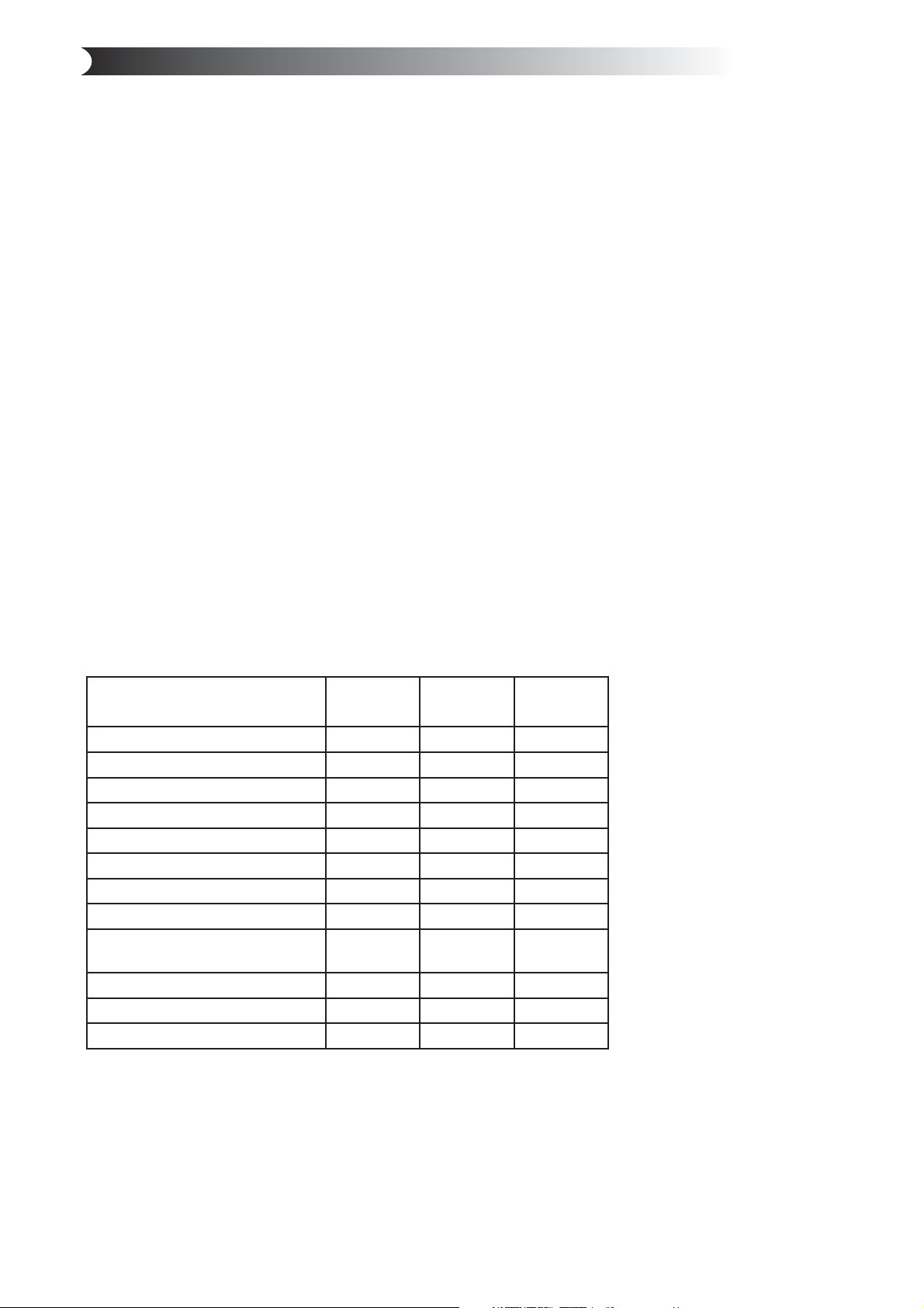
CENTIX 20CENTIX 40CENTIX
50
Height
Width with handles 360 mm 440 mm 440 mm
Length with bracket 400 mm 400 mm 400 mm
Motor
Fuse 10A
Weight 5.5 kg 6.5 kg 6.7 kg
Sound output
Capacity of dust container
Capacity when using dust
bag
Max. suction power
Max. air fl ow 52 l/s 55 l/s 55 l/s
Max. vacuum
These appliances conform with EU directives 89/336/EEC, 73/23/EEC, 93/68/EEC
427 mm 800 mm 800 mm
1500 W 1700 W 1700 W
10 A 10 A
69 dB 70.5 dB 70.5 dB
-
10 l
435 W 480 W 480 W
24 kPa 25 kPa 25 kPa
25 l 25 l
14 l 14 l
30
Page 5

2 Vacuum unit Centix 20 assembly instructions
Fig. 1
2.1 Fitting the mounting bracket
Position the holder so that there is plenty of space above
and below the place where the vacuum unit is to be located.
Make sure there is a minimum of 500 mm free space above
the Centix 20 container. Mark the positions for the four
screw holes with a pen or similar. Then select appropriate
screws and, if necessary, wall plugs for the type of wall
surface to which the bracket is to be attached. Drill the
four holes for the mounting bracket. The diameter of the
screw holes in the holder is 5 mm. Fit the mounting bracket
with the large opening pointing upwards, see Fig. 1. Tighten
the screws so that the holder is held fi rmly in place (screws
provided).
2.2 Locating the vacuum cleaner on the
mounting bracket
Position the vacuum unit so that the mounting bracket is directly
above the wall bracket, see Fig. 2. Lower the machine down on to
the mounting bracket. Make sure the corresponding bracket on
the machine is held fi rmly in place by the wall bracket.
Fig. 2
Fig. 3
Fig. 4
Fig. 5
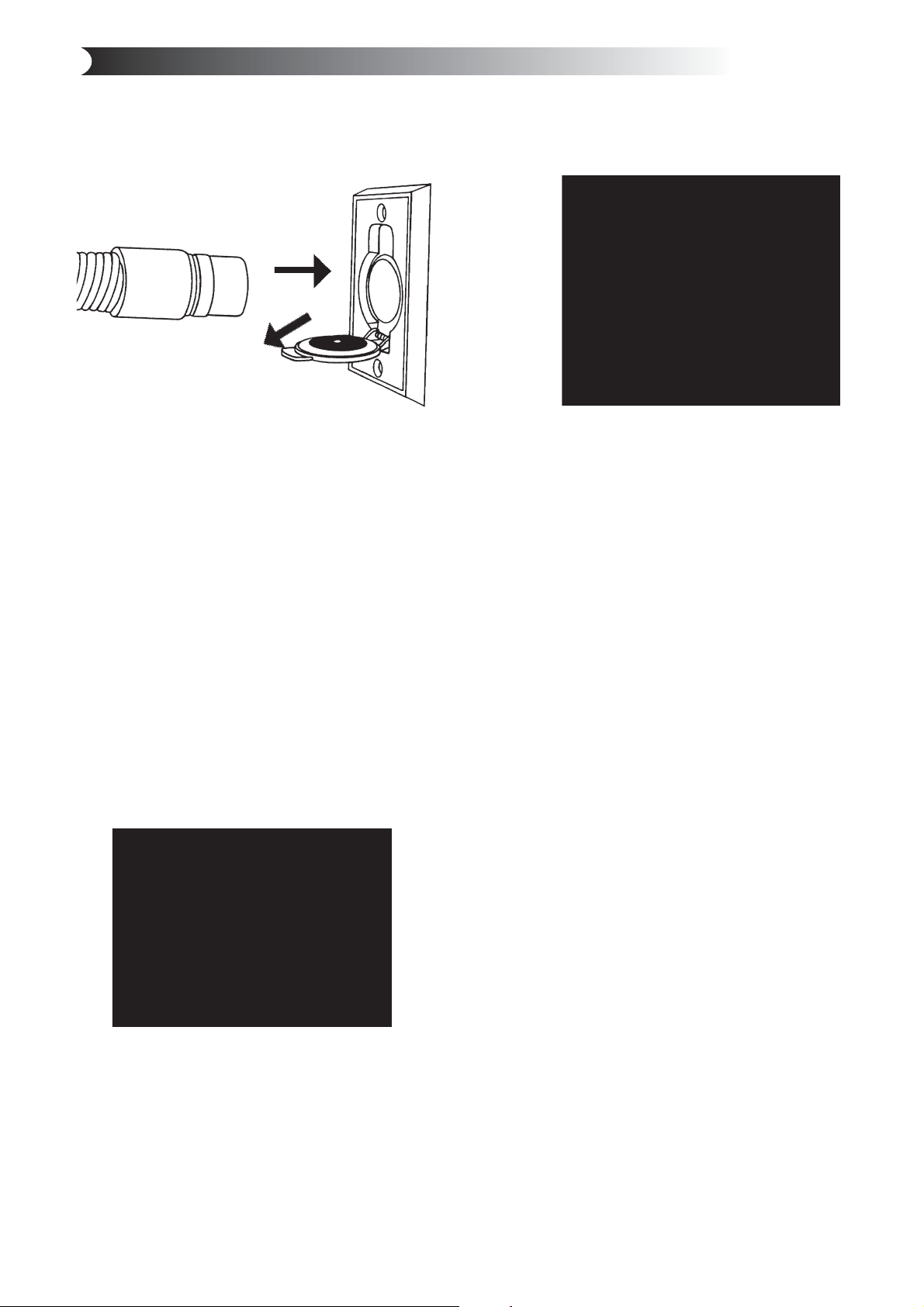
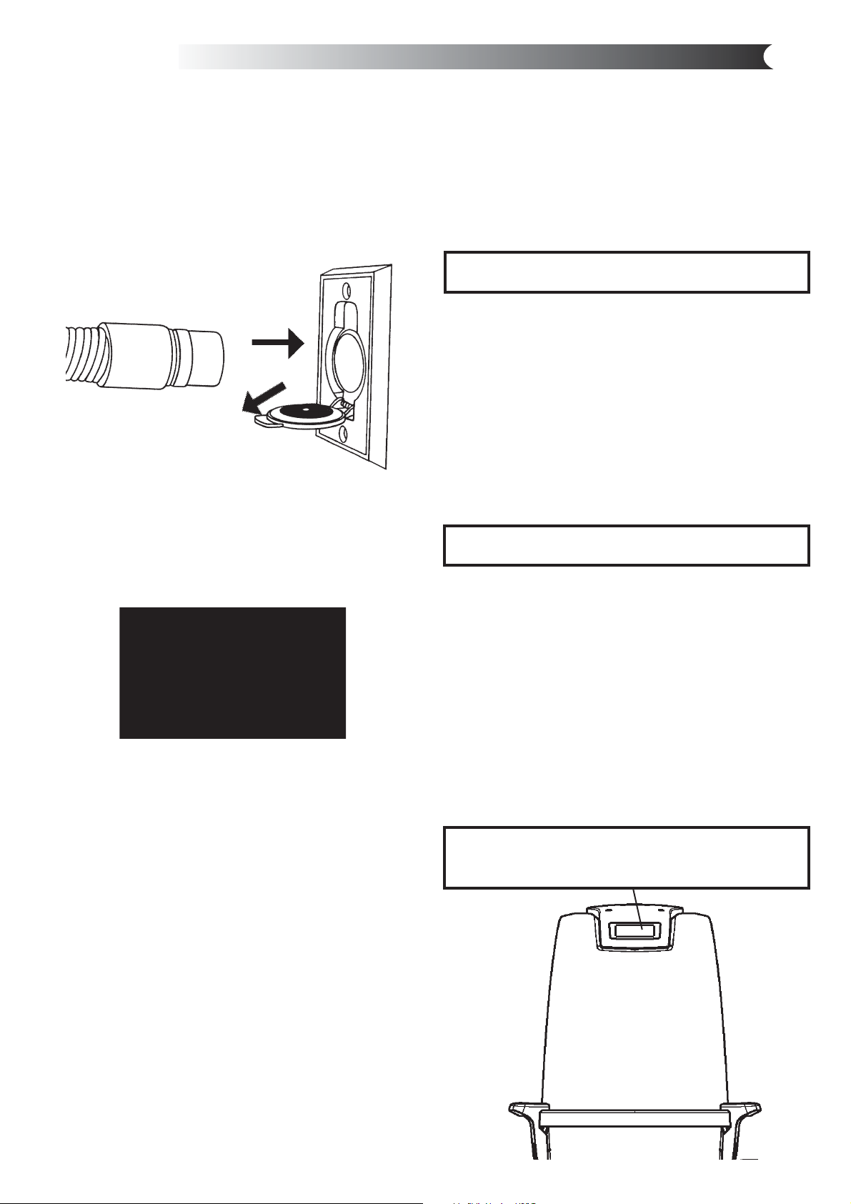
2.3 Connecting the machine
The machine is connected with the suction pipe in the uppermost position and
the exhaust pipe in the lower position.
This connection should not be glued but can be taped when the unit is serviced at
a later date. The suction pipe socket can be fi tted to two different points depending on
the direction in which you would like to install the pipe system.
To relocate the suction pipe socket, you need to do the following:
1. Release the suction pipe socket by unscrewing the four combination Torx screws
with a Torx T20 or an ordinary screwdriver, Fig. 3.
2. Pull the socket out of the machine, see Fig. 4.
3. Loosen the plug blanking off the outlet to which you intend moving the suction
pipe socket. Unscrew the four combination Torx screws. Remove the blanking plug
from the machine.
4. Adapt (move) the suction pipe socket to the new outlet. NB! The socket is marked ”Up”.
Make sure the socket is fi tted with ÏUpÓ uppermost. Fasten the socket by fi tting and tightening the four screws, Fig. 5.
5. Fit the blanking plug to the outlet previously occupied by the suction pipe socket. Use the four screws to hold it in place. The
exhaust pipe must be fi rmly attached to the wall to ensure its connection with the socket does not loosen. Remember that
you will need to be able to turn the bent pipe in different directions to ensure a suitable pipe layout. Then connect up the
exhaust pipe and muffl er, Fig 6. Fit the central vacuum cleaner so that the exhaust pipe is as short as possible, max. 10 metres. Take the surroundings into consideration when positioning the exhaust. For this reason, you should always fi t a muffl er.
For additional information concerning the assembly and installation of the pipe system and low-current lead, please refer to the
separate assembly instructions supplied with the pipe package.
Fig. 6
Inlet
Exhaust
31
Page 6
3 Operating instructions Centix 20
2
1
Fig. 7
3.1 Starting the machine
The control current outlet (low voltage) should be
connected to a control current lead running the length of
the pipes.
Both ends of the low-voltage lead should be connected
to the connection panel on the vacuum cleaner. One lead
to each outlet.
The central vacuum cleaner’s power cable must be
connected to a 230 volt mains socket. The appliance is
double-insulated and does not need to be earthed.
The vacuum cleaner starts and stops automatically.
When the vacuum hose is connected to a vacuum socket,
a metal ring on the end of the hose closes the control
circuit and the vacuum cleaner starts up. 7. When the
hose is removed from the vacuum socket, the vacuum
cleaner stops. You should allow the hose to empty of dust
and dirt before switching the vacuum cleaner off.
Fig. 9
Filter
3.2 Servicing
Always unplug the power cord before
doing any service work!
If suction is poor, it indicates that the fl ow of air through
the machine is restricted. This may be due to the following:
• The dust bag is full and should be replaced.
• The fi lter is clogged and should be cleaned.
The vacuum cleaner has a thermal cut-out that trips if
the vacuum cleaner becomes overheated. If this happens
- unplug the main power cord to reset the vacuum cleaner.
Wait 5-10 minutes to allow the machine to cool down.
While you are waiting, check the hose, dust bag and fi lter
to be sure that nothing is blocking the fl ow of air through
the machine. The vacuum cleaner should now start again.
If the cut-out trips again, you need to get a service fi rm to
remedy the fault.
The Centix 20 should only be operated with a dust bag
and fi lter installed.
Fig. 8
If you use a hose with an on-off switch, you can start
and stop the vacuum cleaner using the switch on the
handle, Fig. 8.
32
Page 7
4 Filter and dust bags - Centix 20
Fig. 10
Fig. 12
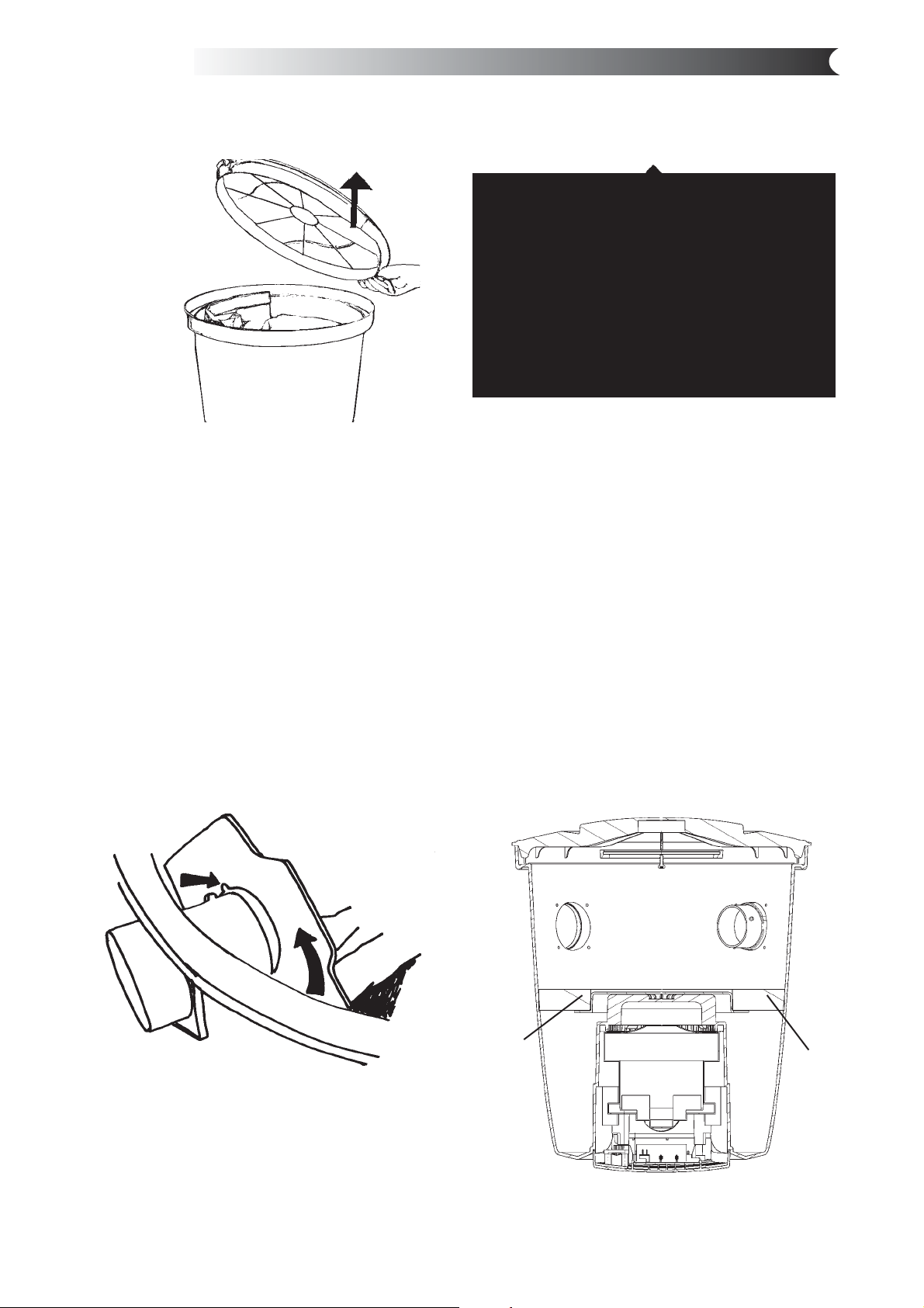
4.1 Replacing the dust bag
The central vacuum cleaner is fi tted with a paper dust
bag as standard; never vacuum without a dust bag
installed.
Grasp the edge of the lid and pull upwards to open it, Fig. 10.
Replacing the dust bag: Remove the old dust bag by
turning the cardboard stiffener to the right or left so that
the raised part of the inlet is in line with the opening in the
card. Now slide the bag off the bag nozzle.
Fit the new dust bag as follows: Push the opening in the
cardboard over the elevation on the inlet and pull on the
new bag. Turn the cardboard to lock the bag in place. NB!
Turn the edges of the dust bag down into the container.
This is to avoid damaging the bag with the lid.
Fig. 11
4.2 Replacing / Cleaning the fi lter
Open the lid and take out the dust bag as described earlier.
The fi lter sits at the bottom of the container around the
motor housing. Never use the central vacuum cleaner
without a fi lter installed.
Pull the fi lter out of the container, Fig. 12. The fi lter can be
cleaned by shaking it or washing it in water.
If you wash the fi lter, you must let it dry completely
before refi tting it.
Take the cleaned fi lter and place it in the bottom of the
container. Press the outer edge of the fi lter down against
the sides of the container so that the fi lter bulges up
slightly. Then push the fi lter down into place. Make sure
the fi lter is packed in tightly against the motor housing,
Fig. 13. Reinstall the dust bag and replace the lid. Check
that the lid is fi rmly secured.
Fig. 13
The cardboard stiffener locks the bag in place when you
twist it as shown in Fig. 11 above.
The opening in the card must line up and slide over the
elevation on the inlet before you twist the cardboard
stiffener to lock it.
33
Filter
Motor housing
Filter
Page 8
5 Vacuum unit Centix 40 / Centix 50 Premium assembly instructions
5.1 Fitting the mounting bracket
Plan the positioning of the mounting bracket so that there
is plenty of space above and below the area where the
vacuum unit is to be located. Make sure there is a minimum
of 400 mm free space below the dust container.
Mark the positions for all four screw holes with a pen or
similar. The diameter of the holes in the holder is 5 mm.
Select screws and, if necessary, wall plugs suitable for the
type of wall concerned. Drill the four screw holes.
Fit the mounting bracket with the large opening pointing
downwards, see Fig. 14. Then screw the holder fi rmly
into place.
Fig. 14
Fig. 15
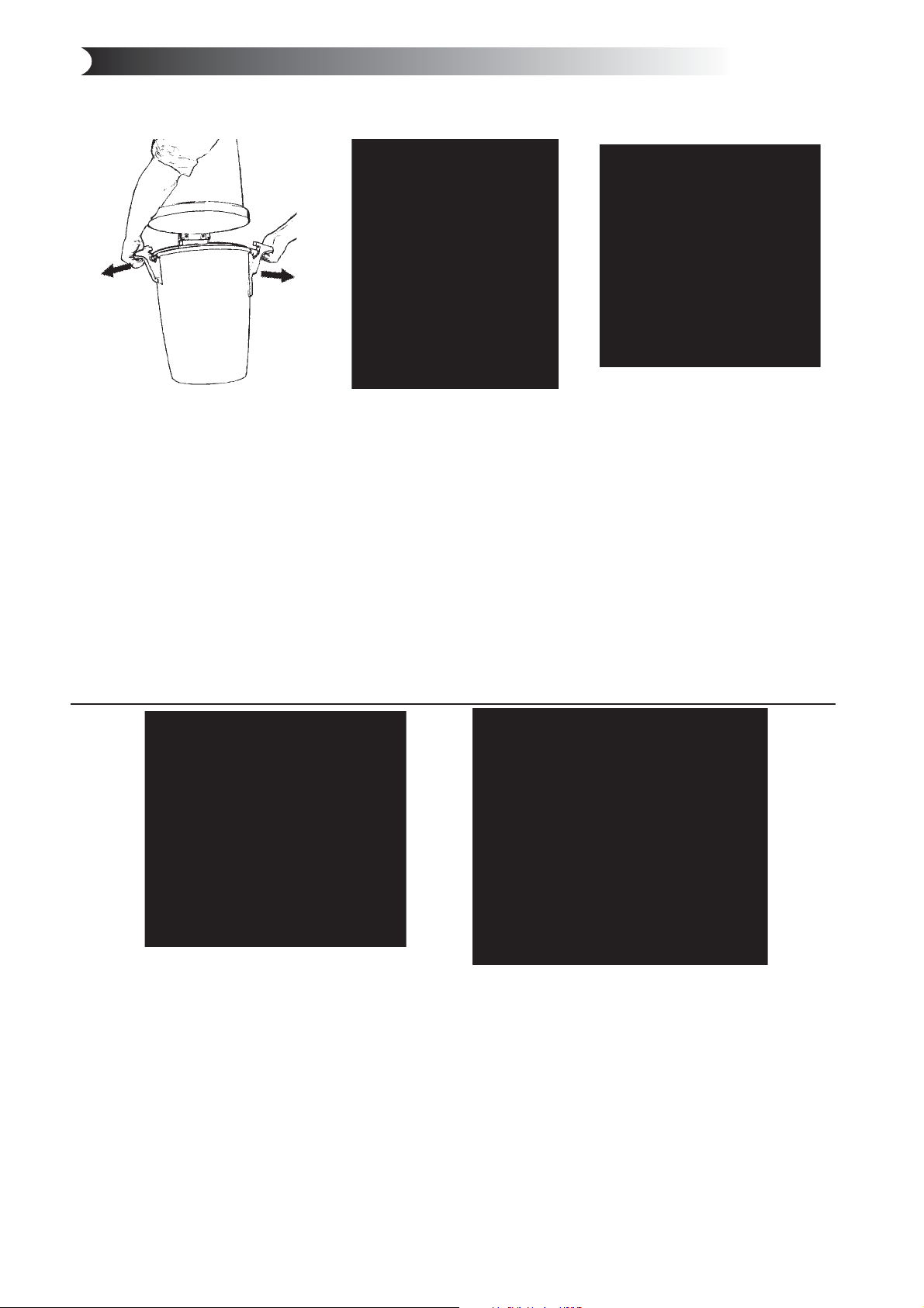
5.2 Locating the vacuum cleaner on
the mounting bracket
To facilitate the procedure, fi rst remove the dust container.
Free the container by pulling both handles outwards. Then
remove the container from the machine. Turn the vacuum
unit until the mounting bracket is immediately below the
bracket on the machine. Lower the machine down on to
the mounting bracket, Fig. 15. Make sure the corresponding
bracket on the machine is held fi rmly in place by the wall
bracket.
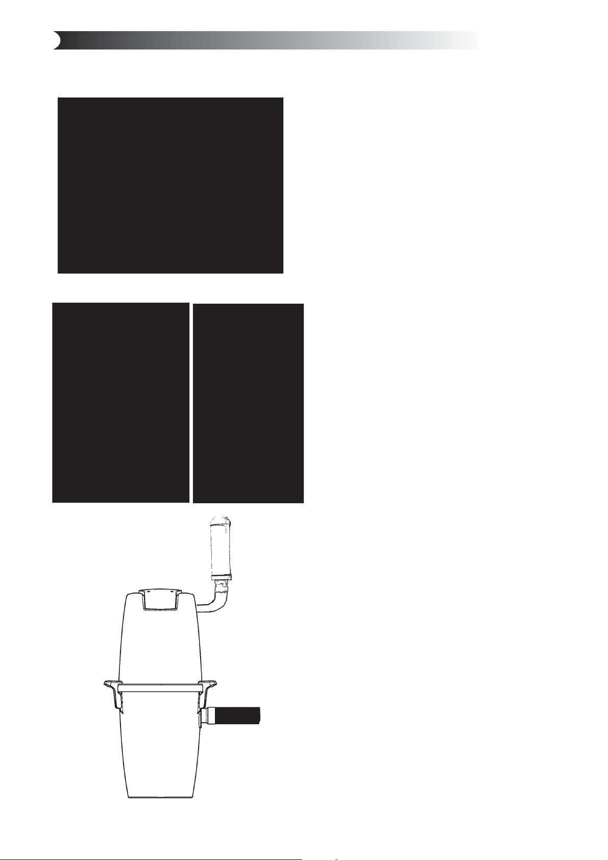
5.3 Connecting the machine
The machine is connected with the fl exible suction hose in
the lower position and the exhaust pipe uppermost, Fig 16.
The fl exible suction hose acts as an adapter connecting
the vacuum unit with the pipe system. The accompanying
rubber sleeve is used for tightening/loosening purposes
between the pipe system and the fl exible vacuum hose.
Feed half the length of the sleeve into the vacuum hose
and fold the other half over. Then feed 5-10 mm of the
vacuum hose into the pipe system and fold the sleeve
back so that it envelopes the tail pipe, holds the
vacuum hose in place and tightens the adapter.
Fig. 16
Exhaust
Inlet
NB! This connection must not be glued in case the unit
is serviced.
Position the central vacuum cleaner so that the exhaust
pipe can be kept as short as possible, max. 10 metres. Take
the surroundings into consideration when positioning the
exhaust. For this reason, you should always fi t a muffl er.
For additional information concerning the assembly and
installation of the pipe system and low-current lead, please
refer to the separate assembly instructions supplied with
the pipe package.
34
Page 9
6 Operating instructions Centix 40 / Centix 50 Premium
6.1 Starting the machine
The control current outlet (low voltage) is connected to a
control current lead running the length of the pipes. Both
ends of the low-voltage lead should be connected to the
connection panel on the vacuum unit. One lead to each outlet.
The central vacuum cleaner’s power cable must be connected
to a 230 volt mains socket. The appliance is double-insulated
and does not need to be earthed.
Fig. 17
2
1
The vacuum cleaner starts and stops
automatically. When the vacuum hose is connected to a
vacuum socket, (Fig. 17) a metal ring on the end of the hose
closes the control circuit and the vacuum cleaner starts up.
When the hose is removed from the vacuum socket, the
vacuum cleaner stops. You should allow the hose to empty of
dust and dirt before switching the vacuum cleaner off.
6.3 Centix 50 Premium Display
The Centix 50 Premium model has a display giving information
about the machine, Fig. 19. The display is illuminated and lights
up on start-up. The display remains illuminated for 15 minutes
after the machine has been switched off. This allows you to
check the current status of the machine after it has been in
operation.
The following information is shown on the display:
Run: 301h 01m 11s
* Run: Shows the machine’s total operating hours, ie, the
period of time the motor has been in operation. The time is
shown in hours, minutes and seconds. When the machine has
been in operation for approximately 700 hours, it will stop.
You must then make immediate contact with an authorised
service workshop for a replacement motor to be installed. You
can reset the machine temporarily and run the motor for an
additional 100 hours (approximately) by unplugging the power
cable and then reconnecting it to the mains socket. Once you
reach the end of the 100 hours of operating time, the machine
will stop again. It will now be necessary for an authorised
service workshop to replace the motor and reset the clock.
Filter / Bag: 80%
Fig. 18
If you use a hose with remote control, you can start and stop
the vacuum cleaner using the switch on the handle, Fig. 18.
6.2 Servicing
Always unplug the power cable before doing any service work!
If suction is poor, it indicates that the fl ow of air through the
machine is restricted. This may be due to the following:
• The dust bag is full and should be replaced.
• The fi lter is clogged and should be cleaned of dust.
The vacuum cleaner has a thermal cut-out that trips if the
vacuum cleaner becomes overheated. If this happens - unplug
the main power cored to reset the vacuum cleaner. Wait 510 minutes to allow the machine to cool down. While you are
waiting, check the hose, dust bag and fi lter to be sure that
nothing is blocking the fl ow of air through the machine. The
vacuum cleaner should now start again. If the cut-out trips
again, you need to get a service fi rm to remedy the fault.
The Centix 40/Centix 50 Premium can be run with or
without the installation of a dust bag - the choice is yours.
These products must always be operated with a bag fi lter
fi tted.
* Filter/Bag: Shows the remaining capacity of the dust bag
and bag fi lter. The indication is shown as a percentage. 0% is
displayed when the bag/bag fi lter is empty. Indication is then
given in increments of 10% at a time. When 90% capacity has
been reached, the display will warn you with the following
fl ashing message: Check fi lter. You should then replace the
dust bag and bag fi lter as soon as possible; see section on fi lter
and dust bag. Once the dust bag has been replaced, reset the
machine by starting it up again. The indication should then
display 0% again.
The panel on the Centix 50 Premium displays relevant
information about the machine.
Run: 301h 01m 11s
Filter / Bag: 80%
Fig. 19
35
Page 10
7 Filter and dust bags - Centix 40 / Centix 50 Premium
Fig. 20
7.1 Replacing the bag fi lter
A bag fi lter must always be installed in the dust container.
Clean the fi lter in the following way:
1. Start by pulling the pipe socket out of the dust
container.
2. Release the two handles clamping the dust container.
Free them by pulling the handles outwards away from
the container, Fig 20.
3. Do not remove the fi lter from the container. Instead,
give the fi lter a light shaking inside the container to
loosen dust from the fi lter allowing it to fall into the
container, Fig. 21.
4. Lift out the bag fi lter. If a dust bag is being used remove the dust bag. Then empty the container of any
remaining dust in a suitable place.
Fig. 21
Fig. 22
7.2 Fitting the bag fi lter
Replace the bag fi lter in the machine as follows:
1. Replace the cleaned/shaken bag fi lter in the
container, Fig. 22. Make sure the fi lter support fi ts into
the inner edge of the dust container properly. Check
that the fi lter is fi tted the right way up - the cloth
handle on the fi lter should be visible.
2. Then replace the dust container with the bag fi lter in
the cleaner’s vacuum unit.
3. Close the container on the vacuum unit by applying
inward pressure to the two handles to ensure the
vacuum unit and dust container are fi tted together
properly.
4. Fit the inlet socket to the machine.
Fig. 23
7.3 Replacing the dust bag
The machine is supplied with a paper dust bag.
Replace the dust bag in the following way:
1. Pull the inlet socket out of the machine.
2. Release the two handles clamped on to the dust
container. Free them by pulling the handles outwards
away from the container.
3. Lift off the container.
4. Shake the dust from the bag fi lter. It may be
advantageous for the fi lter to be installed in the
container in such a way that dust in the fi lter can be
shaken down into the dust container.
5. Lift out the bag fi lter.
6. Remove the dust bag by taking hold of the cardboard
stiffener and carefully pulling out the card and bag
from the container, Fig. 23.
7. Empty the container of dust.
Fig. 24
7.4 Fitting the dust bag
Replace the dust bag as follows:
1. Fit the dust bag’s card with a hole into the bag holder,
Fig. 24.
2. Replace the cleaned/shaken bag fi lter in the
container. Make sure the fi lter support fi ts into the
inner edge of the dust container properly.
Check that the fi lter is fi tted the right way up - the
cloth handle on the fi lter should be visible, Fig. 22.
3. Replace the dust container on the vacuum unit. Close
the container on the vacuum unit by applying inward
pressure to the two handles to ensure the vacuum unit
and dust container are fi tted together properly.
4. Replace the inlet socket in the machine.
36
Page 11
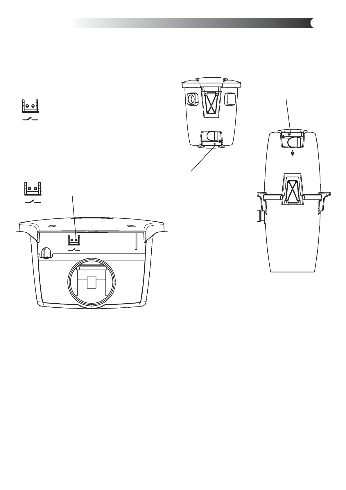
8 Electrical connection
On/Off
The control current outlet (low voltage) is connected to
a control current lead running the length of the pipes.
Both ends of the low-voltage lead are connected to the
connection panel on the vacuum unit. One lead to each
outlet. The low-voltage lead should be connected as
illustrated below.
The central vacuum cleaner’s 230 volt power cord must
be connected to a 230 volt mains socket. The appliance is
double-insulated and does not need to be earthed.
The low-voltage lead is connected to this outlet.
Outlet for the low-voltage leads:
Centix 20
Centix 40
Centix 50 Premium
The connection panel is
located in the top of the
Centix 40 and Centix 50
Premium vacuum unit.
Centix 20
The connection panel is
located in the bottom of
the Centix 20 vacuum
unit.
37
Page 12
8 Accessories
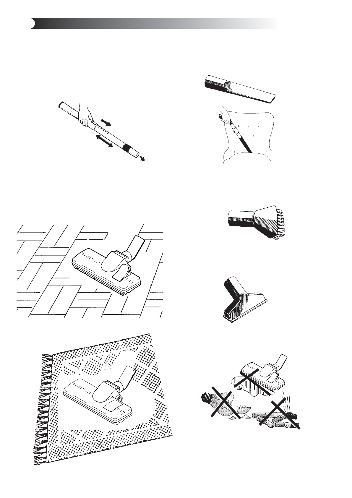
Telescopic tube
Adjust the length of the telescopic tube by pressing the
button and sliding it in or out. 25. (Maximum length 1000
mm and minimum length 600 mm). For cleaning stairs,
we recommend reducing the length of the tube to the
minimum.
Fig. 25
Standard fl oor nozzle
This is a universal, lightweight fl oor nozzle that can be
used on most fl oor surfaces. You can switch from cleaning
carpets to parquet or other fl ooring, Fig. 26/27.
Fig. 26
Radiator/crevice nozzle
This nozzle is useful for hard-to-reach, restricted areas
such as corners, crevices and radiators.
Fig. 28
Fig. 29
Dusting brush
The dusting brush can be used on lamps, pictures,
curtains and other textiles, Fig. 30.
Fig. 30
Fig. 27
Furniture nozzle
Small, practical nozzle for vacuuming furniture, cushions
and textiles, Fig. 31.
Fig. 31
Remember!
Never vacuum up liquids, broken glass
or hot ash.
Fig. 32
38
Page 13

10 Troubleshooting
All work involving the 240 volt mains electricity
supply must be carried out by a qualifi ed electrical
contractor with full knowledge of the relevant safety
regulations.
The vacuum cleaner will not start
The vacuum cleaner is fi tted with a thermal cut-out that
may have tripped. If this happens - unplug the main
power cord from the wall socket. Wait fi ve minutes to
allow the machine to cool down. While you are waiting,
check the fi lter and dust bag to be sure that nothing is
blocking the fl ow of air through the machine. After fi ve
minutes, plug the power cord back into the wall socket.
The vacuum cleaner should now start again. If the cut-out
trips again, you need to get a service fi rm to remedy
the fault.
• Are you using the correct hose?
Only the original hoses fi t correctly.
• Does the vacuum cleaner start when you try a
different vacuum socket? If so, there is a fault in the
electrical connection to the fi rst socket. Unscrew the
socket and check the connection at the back.
• Is the power supply connected to the vacuum unit?
• Is there power at the socket?
• Is the low-voltage lead connected to the vacuum unit?
The vacuum cleaner will not stop
• Has a metal object become lodged in one of the
vacuum sockets causing the pins to become fused?
Centix 50 Premium display
The Centix 50 Premium model has a display that shows
relevant status. The display shows the machine’s total
operating hours (Run) It also shows the remaining
capacity of the fi lter and dust bag (Filter / Bag).
* Run: Shows the machine’s total operating hours, ie, the
period of time the motor has been in operation. When the
machine has been in operation for approximately 700
hours, it stops. You must then make immediate contact
with an authorised service workshop for a replacement
motor to be fi tted. You can reset the machine temporarily
and run the motor for an additional 100 hours
(approximately) by unplugging the power cable and then
reconnecting it to the mains socket. Once you reach the
end of the 100 hours of operating time, the machine will
stop again. It will now be necessary for an authorised
service workshop to replace the motor and reset the clock.
* Filter/Bag: Shows the remaining capacity of the
dust bag and bag fi lter. The indication is shown as a
percentage. 0% is displayed when the bag/bag fi lter is
empty. Indication is then given in increments of 10% at a
time. When 90% capacity has been reached, the display
will warn you with the following fl ashing message: Check
fi lter. You should then check the fi lter and replace the
dust bag and bag fi lter as soon as possible; see section on
fi lter and dust bag. Once the dust bag has been replaced,
reset the machine by starting it up again. The indication
should then display 0% again.
Poor suction power
• Are all the vacuum sockets closed properly?
• Has something become jammed in one of the vacuum
sockets?
• Is the container lid closed properly?
• Is the gasket between the container and the lid in
place?
• Is it damaged?
• Is the pipe system blocked?
• Is the dust bag full or clogged? Model Centix 50
Premium issues a warning with a message on the
panel.
• Is fi lter clogged? Model Centix 50 Premium issues a
warning with a message on the panel.
Service and spare parts
If you need a service or spare parts, contact your local
dealer. In such circumstances, it is always useful if you
can give the technical data shown on the rating plate of
the vacuum unit. The rating plate is adjacent to the lead
intake. It’s a good idea to copy this data here so that it is
readily to hand.
Model: ........................................................................................
Product no.: ...............................................................................
Serial no.: ...................................................................................
Date of purchase: ....................................................................
(please keep your receipt)
39
Page 14
10.1 Service/maintenance guide - Centix 20
NB! Never vacuum without a fi lter and dust bag installed.
Product How often? Why? How?
Dust bag
Filter in
bottom
Should be replaced
before it becomes
completely full,
depending on use but
normally 2-4 times a
year.
Should be checked
when changing
the bag.
Poor suction and
danger of
creating a
blockage in
the pipe system.
Poor suction can
result. Dust can
fi nd its way into
the motor.
Grasp the edge of the lid and open it by pulling upwards.
Remove the old dust bag by turning the cardboard
stiffener to the right or left so that the elevation on
the nozzle penetrates the opening in the cardboard.
Now slide the bag off the inlet. Push the opening in the
cardboard over the elevation on the inlet and pull on
the new bag. Twist the cardboard to lock the bag in
place. NB! The opening in the card must be adjusted
and pushed past the elevation on the inlet before the
cardboard can be locked into place with a twisting action.
NB! Never vacuum without a dust bag installed.
Remove the dust bag as described above. Remove
the fi lter from the bottom. The fi lter can be cleaned by
shaking it or washing it in water. NB! The fi lter must be
completely dry before being reinstalled. Replace the
cleaned fi lter in the machine. Press the outer edge of the
fi lter down against the sides of the container so that the
fi lter bulges up slightly. Refi t the dust bag and replace the
lid. Check that the lid is sitting fi rmly in place.
NB! Never vacuum without a fi lter installed.
10.2 Service/maintenance guide - Centix 40 / Centix 50 Premium
NB! Never vacuum without a fi lter installed.
Product How often? Why? How?
Dust
container
Dust bag
Filter
Should be emptied
before the container
is 3/4 full, depending
on use but normally
2-4 times a year.
Should be replaced
before it becomes
completely full,
depending on use but
normally 2-4 times
a year.
Should be shaken
when the container is
emptied.
NB: Only use dry
cleaning methods
Danger of
blockage in the
pipe system.
Poor suction
and danger
of creating a
blockage
in the pipe
system.
To maintain good
suction power.
Remove the hose from the machine. Then loosen the
handles on the container (pull out from the machine) to
free the container from the machine. Lift out the fi lter
and dust bag - see additional information below. Empty
the dust into a plastic bag and put in dustbin. Any
remaining dust or fl uff can be removed manually.
Remove the hose from the machine. Then loosen the
handles on the container (pull out from the machine)
to free the container from the machine. Lift off the
container. Lift out the fi lter. Then remove the dust bag
by pulling the bag’s cardboard stiffener off the nozzle.
Replace in reverse order.
Start by pulling the hose out of the dust container.
Loosen the handles on the container by pulling the
handles in an outward direction from the machine.
Remove the container from the machine.
Do not remove the fi lter from the container. Instead, give
the fi lter a light shaking inside the container to loosen
dust from the fi lter and allow it to fall into the container.
Lift out the bag fi lter. If a dust bag is being used remove it. Then empty the dust from the container in a
suitable place.
40
Page 15
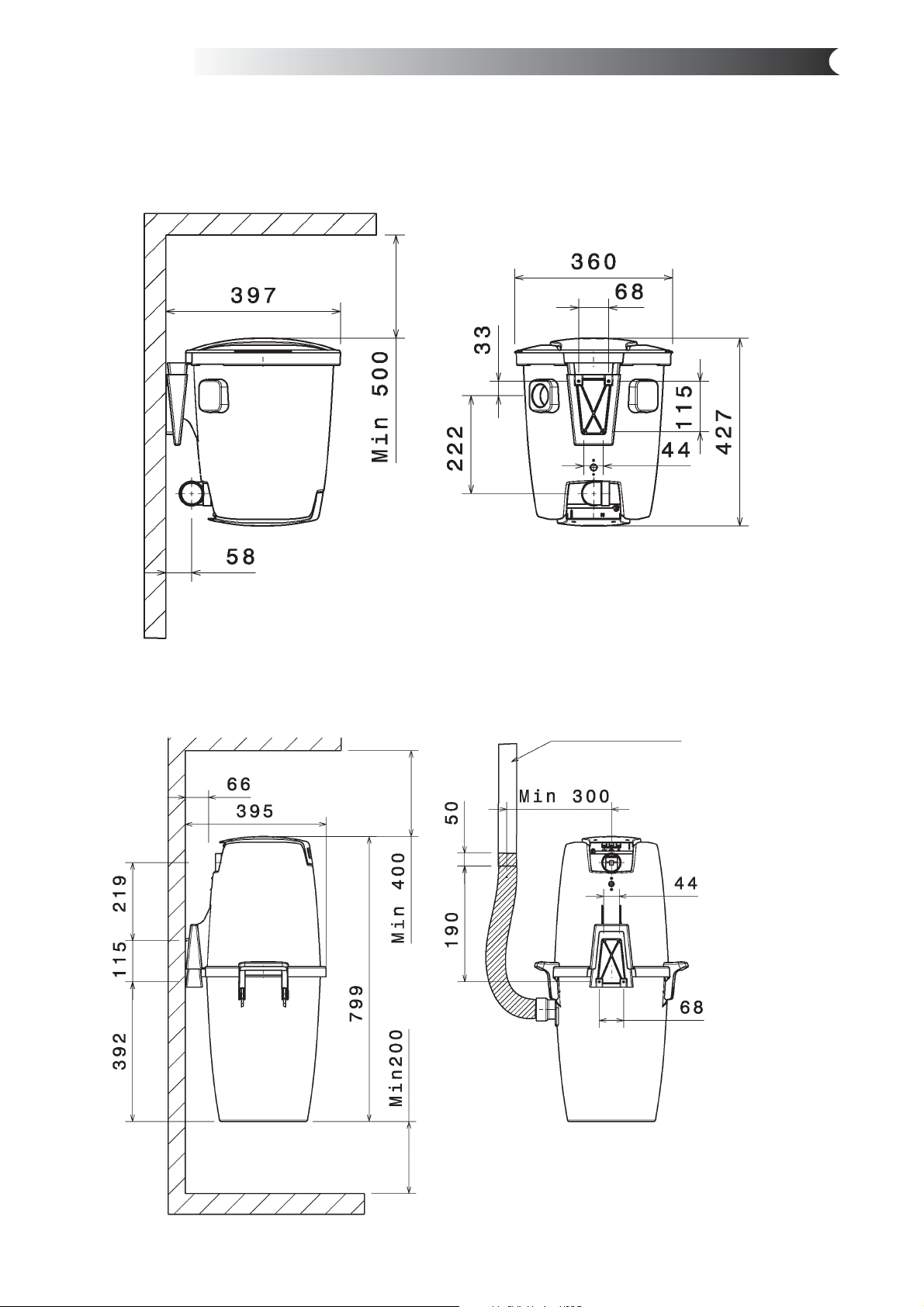
11 Dimensional drawings Centix 20 / Centix 40 / Centix 50 Premium
Dimensional drawings in mm.
Centix 20
Centix 40 / Centix 50 Premium
Attach to wall
41
Page 16

Page 17

CENTIX 60
CENTIX 60 PREMIUM
english Operating Instructions..................................... 1
deutsch Betriebsanleitung...........................................13
français Notice d’utilisation......................................... 25
nederlands Gebruiksaanwijzing ....................................... 37
norsk Driftsinstruks..................................................49
svensk Bruksanvisning .............................................. 61
dansk Driftsvejledning..............................................73
suomi Käyttöohje.......................................................85
302001245 - 2003-11-03
Page 18

#%.4)8
#%.4)802%-)5-
#%.4)8
#%.4)802%-)5-
Page 19

Contents
1 Important safety
instructions
2 Description
3 Before start-up
4 Operation
5. Applications and
techniques
6 After finishing work
7 Maintenance
8 Troubleshooting
9 Further information
CENTIX 60 PREMIUM
............................................................................................2
2.1 Operating elements..............................................................4
3.1 Assembling the cleaner ........................................................4
3.2 Fixing wall bracket................................................................4
3.3 Fitting suction hose and waste air hose ...............................5
4.1 Connections .........................................................................5
4.1.1 Electrical connection ............................................................5
4.1.2 Connection diagram for central extraction system ...............5
4.2 Operation with central extraction system..............................6
4.3 Mobile operation...................................................................6
4.3.1 Changing suction hose for mobile operation ........................6
4.3.2 Switching on cleaner ............................................................6
5.1 Techniques ...........................................................................7
5.1.1 Picking up dry substances ...................................................7
6.1 Storing suction hose and accessories..................................7
6.2 After mobile operation of the cleaner ...................................7
7.1 Maintenance plan.................................................................8
7.2 Maintenance work................................................................8
7.2.1 Emptying dirt tank ...............................................................8
7.2.2 Replacing the filter bag.........................................................8
7.2.3 Replacing the filter element..................................................9
............................................................................................9
9.1 Recycling the vacuum cleaner ...........................................10
9.2 Guarantee ..........................................................................10
9.3 Tests and approvals ...........................................................10
9.4 Technical data ....................................................................11
9.5 Accessories........................................................................11
9.6 EC declaration of conformity ..............................................12
CENTIX 60
english
1
Page 20

CENTIX 60
CENTIX 60 PREMIUM
english
1 Important safety instructions
Symbols used to mark
instructions
them readily available.
prevent damage to persons.
For your own safety Only allow the vacuum cleaner
Purpose and intended use
to be used by persons who have
been trained in its use and who
have been explicitly authorized
to use it.
Despite its simple handling the
vacuum cleaner is not suitable
for children.
The use of the vacuum cleaner
is subject to valid national regulations.
The cleaners described in these
operating instructions are designed for use in dry conditions and
should not be used or stored
outside in wet conditions.
The following materials should
not be picked up by the vacuum
cleaner:
Before using the
vacuum cleaner,
always read the
operating instructions and keep
This symbol is
used to mark
safety instructions that must
be observed to
This symbol is
used to mark
safety instructions that must
be observed to
prevent damage
to the vacuum cleaner and its
performance.
This symbol indicates tips and
instructions
to simplify work and to ensure
safe operation.
Besides the operating instructions and the binding accident
prevention regulations valid in
the country of use, observe recognized regulations for safety
and proper use.
Do not use any unsafe work
techniques.
– hazardous dust
– hot materials (burning ciga-
rettes, hot ash, etc.)
– flammable, explosive dust (e.g.
magnesium or aluminium dust,
etc.)
– liquids
Precautions and safety regulations when using the vacuum cleaner
2
Before start-up
Inspect power cord regularly
to detect signs of damage, e.g.
cracks or ageing.
If the power cord is damaged, it
must be replaced by Alto-Service or an electrician to avoid
danger before use of the vacuum cleaner is continued.
Page 21

Use only the type of power cord
specified in the operating manual. Do not damage the power
cord (e.g. by moving over it or
pulling or crushing it). Disconnect the power cord by pulling
the plug only (do not pull or tug
the power cord).
Inspect the vacuum cleaners to
ensure that they are in proper
condition. Plugs and couplings
in power cords must at least
have splash protection.
Never use the vacuum cleaner if
the filter element is damaged.
Electrical components
Check the rated voltage of the
vacuum cleaner before connecting it to the mains supply
system. Ensure that the voltage
shown on the rating plate corresponds to the voltage of the
local mains power supply.
If you are using an extension
cord, use only those specified
by the manufacturer or higher
quality ones (see section 9.4
„Technical data“).
CENTIX 60 PREMIUM
It is recommended that the
vacuum cleaner should be connected via a residual current
circuit breaker. This stops the
supply of electricity if the leakage current to earth exceeds 30
mA for 30 ms or it has an earth
tester circuit.
Arrange the electrical parts
(sockets, plugs and couplings)
and lay down the extension lead
so that the protection class is
maintained.
Never spray water on to the upper section of the vacuum cleaner. Danger for persons, risk or
short-circuiting.
Observe the latest edition of the
IEC regulations.
CENTIX 60
english
Maintenance, cleaning and
repair
Accessories and spare parts
Only carry out maintenance
work described in the operating
instructions.
Use only the brushes supplied
with the vacuum cleaner or specified in the operating manual.
The use of other brushes can
adversely affect safety.
Always pull out the mains plug
before cleaning and maintenance of the vacuum cleaner.
Use only original Alto accessories and spare parts (see section 9.5). The use of other parts
can adversely affect safety.
3
Page 22

CENTIX 60
CENTIX 60 PREMIUM
english
2 Description
2.1 Operating elements
See fold-out page at the front of
these operating instructions.
1 Handle with cable hook
2 Accessory holder
3 Cleaner switch
3 Before start-up
3.1 Assembling the cleaner
1. The mains plug should not
be inserted into a socket.
2. Open the retaining clamps
(1) and lift off the upper section of the cleaner.
3.2 Fixing wall bracket
4 Retaining clamp
5 Dirt tank
6 Grip to empty tank
7 Inlet fitting
8 Plug for mobile operation
9 Waste air connection
3. Take the accessories out
of the dirt tank and the packaging.
4. Place a filter bag into the
tank as described in the
instructions (printed on the
filter bag).
IMPORTANT: Press the filter
bag connection firmly on to
the inlet fitting.
5. Fit the upper section of the
cleaner and close the retaining clamps, taking care not
to damage the filter bag.
NOTE: Ensure that the retai-
ning clamps fit properly.
At the installation site:
1. Screw the holding bar on to
the rear of the suction unit.
2. Fix the wall bracket on the
wall.
3. Hang the cleaner on the wall
bracket.
4
Page 23

3.3 Fitting suction hose
and waste air hose
4 Operation
CENTIX 60
CENTIX 60 PREMIUM
1. Suction hose, 1 m:
Screw 90° bush (1) on to one
end of the suction hose (left
thread).
2. Waste air hose, 1 m:
2
1
Screw rotatable bush ø50 mm
(2) on to one end of the suction hose.
3. Connect the hoses to the
cleaner and the system as
shown in the diagram.
english
4.1 Connections
4.1.1 Electrical connection
4.1.2 Connection diagram
for central extraction
system
The operating voltage shown on
the rating plate must correspond
to the voltage of the mains power supply.
1. Ensure that the vacuum
cleaner is switched off.
2. Insert the power cord into a
properly installed and fused
socket with an earthing contact.
®
302 001 193 / 302 001 194
5
Page 24

CENTIX 60
CENTIX 60 PREMIUM
english
4.2 Operation on central
extraction system
Connect only plugs to the cleaner socket that have been ap-
0
proved by Alto.
1. Ensure that
– the cleaner is switched
off
– the suction sockets are
not activated.
1
2
2. Connect the plug of the central extraction system (1) to
the control panel.
3. Turn the switch to position
„I“.
4. Insert the suction hose in the
suction socket.
CENTIX 60:
The vacuum cleaner motor
starts.
5. CENTIX 60 PREMIUM:
Switch the suction motor on
and off at the switch (2) on
the suction pipe handle.
4.3 Mobile operation
4.3.1 Changing suction hose
for mobile operation
4.3.2 Switching on cleaner
CENTIX 60:
1. Unscrew suction hose bush
(ø 32 mm) from the suction
hose (left thread).
2. Screw ø32/50 mm bush (1)
on to one end of the suction
hose (left-handed thread).
CENTIX 60 PREMIUM:
1. Use the suction hose sup-
1
1
1
plied for mobile operation.
Connect only plugs to the cleaner socket that have been approved by Alto.
0
1. Ensure that the tool is switched off.
2. Insert the plug for mobile
operation (1) into the cleaner
socket.
3. Connect the suction hose to
the inlet fitting (1).
4. Turn the switch to position
„I“.
The vacuum cleaner motor
starts.
6
Page 25

5 Applications and techniques
CENTIX 60
CENTIX 60 PREMIUM
english
5.1 Techniques
5.1.1 Picking up dry
substances
If used correctly, additional accessories, suction nozzles and
suction hoses can enhance the
cleaning action and reduce the
cleaning effort.
CAUTION:
The following materials should
not be picked up by the vacuum
cleaner:
– hazardous dust
– hot materials (burning ciga-
rettes, hot ash, etc.)
– flammable, explosive dust
(e.g. magnesium or aluminium
dust, etc.)
– liquids
6 After finishing work
6.1 Storing suction hose
and accessories
6.2 After mobile operation
of the cleaner
CAUTION: Danger of tripping.
To prevent accidents:
1. Wind up the suction hose
and hang it up on the wall
Effective cleaning is achieved if
you follow just a few guidelines
in combination with your own
practical experience in special
fields.
Here are some basic tips.
Before picking up dry substances, always ensure that a
filter bag is inserted in the tank
(see section 9.5 „Accessories“
for order number). Disposal of
the picked up material is then
simple and hygienic.
bracket supplied.
2. Store the suction pipe/nozzle
and other accessories in a
suitable place.
1. Switch off the vacuum cleaner and pull the mains plug
out of the socket.
2. Empty the tank and clean the
vacuum cleaner.
3. Wind up the suction hose
and store the suction pipe/
nozzle and other accessories in a suitable place.
4. Wind up the power cord and
hang it on the handle.
or
5. Reconnect the cleaner to the
central extraction system.
7
Page 26

CENTIX 60
CENTIX 60 PREMIUM
english
7 Maintenance
7.1 Maintenance plan
7.2.1 Emptying dirt tank
7.2.2 Replacing the filter bag
7.2.3 Replacing the filter element
7.2.4 Check that the hose of the level indicator and
accessories are not blocked and clean them.
As required
z
z
z
z
7.2 Maintenance work
7.2.1 Emptying dirt tank
7.2.2 Replacing the filter bag
Empty the dirt tank if you use
the vacuum cleaner without a
filter bag:
1. Remove the upper section of
cleaner from the dirt tank.
2. Using one hand, take hold of
the dirt tank underneath and
tip out the dirt.
3. Dispose of the dirt in accordance with legal regulations.
4. Clean the rim of the tank.
5. Attach the upper section of
the cleaner.
6. Clean the inlet fitting and
hose collar.
7. Re-insert the suction hose.
1. Remove the upper section of
cleaner from the dirt tank.
2. Carefully remove the filter
bag connection from the inlet
fitting.
3. Close the filter bag connection with the slide.
4. Dispose of the filter bag in
accordance with legal regulations.
5. Place a new filter bag into the
cleaned tank as described in
the instructions (printed on
the filter bag).
IMPORTANT:
Press the filter bag connection
firmly on to the inlet fitting.
8
Page 27

7.2.3 Replacing the filter
element
8 Troubleshooting
CENTIX 60
CENTIX 60 PREMIUM
3
2
1. Remove the upper section of
the cleaner from the dirt tank
and deposit it with the filter
element facing upwards. Do
not place the upper section
1
4
of the cleaner on the guard
(1).
2. Turn the filter holder anticlockwise (2) and remove it (3).
3. Carefully remove the filter
element.
4. Clean the filter seal (4).
Check it for damage and
replace it if necessary.
5. Fit a new filter element.
6. Fit the filter holder and turn it
clockwise to secure it.
7. Dispose of the used filter
element in accordance with
legal regulations.
CAUTION:
Never use the vacuum cleaner
without a filter.
english
Fault Cause Remedy
‡ Motor does not start. > Fuse of the mains socket has
blown
> Plug not inserted for opera-
tion on the central extraction
system/mobile operation
> Overload protection switch
has tripped
‡ Motor runs continuously > Plugs for mobile operation
and for central extraction system are both inserted
‡ Reduced suction power > Clogged suction hose/nozzle • Clean suction hose/nozzle
> Seal/tank rim between the up-
per section of the cleaner and
the dirt tank is dirty/defective
> Filter bag is full • See section 7.2.2 „Replacing
> Filter element is clogged • See section 7.2.3 „Replacing
• Reset the fuse
• Insert the plug into the cleaner socket. See sections 4.1.3
and 4.1.4
• Switch off the vacuum cleaner
and allow it to cool for approx.
5 minutes. If the cleaner cannot be started again, contact
the Alto service department.
• Insert only one of the two
plugs into the cleaner socket
• Clean/replace seal
filter bag“
filter bag“
-->
9
Page 28

CENTIX 60
CENTIX 60 PREMIUM
english
‡ Voltage fluctuations > Impedance of power supply is
Fault Cause Remedy
9 Further information
too high
• Use a suitable extension
cord (see sections 1, „Safety
instructions“, and 9.4, „Technical data“)
• Connect the cleaner to another socket closer to the fuse
box. Voltage fluctuations over
7% should not occur if the impedance at the transfer point
is ≤0.15 Ω.
9.1 Recycling the vacuum
cleaner
9.2 Guarantee
9.3 Tests and approvals
10
Make the old cleaner unusable
immediately.
1. Unplug the cleaner and cut
the power cord.
Our general conditions of business are applicable with regard
to the guarantee.
The vacuum cleaners must be
inspected regularly in accordance with national accident
prevention regulations (in Germany as specified in VBG 4 and
DIN VDE 0701 Part 1 and Part
3, at regular intervals and after
repairs or modifications).
The cleaner contains valuable
materials that should be recycled. Therefore, make use of your
local waste disposal site.
Contact your local authorities or
your nearest dealer for further
information.
Subject to change as a result of
technical advances.
The vacuum cleaner has been
approved in accordance with
IEC/EN 60336-2-2.
Page 29

9.4 Technical data
CENTIX 60 / CENTIX 60 PREMIUM
EU
Voltage V 230
Mains frequency Hz 50/60
Power consumption W 1200
Fuse A 16
Volume flow (air) max. l/min 3600
Negative pressure max. Pa 23000
Sound pressure level dB(A) 62
Operating noise dB(A) 59
Power cord length m 7,5
Power cord type H05VV-F 2 x 0,75
Protection class II
Radio interference level EN 50014-1
Tank volume l 27
Width mm 380
Depth mm 390
Height mm 570
Weight kg 10
CENTIX 60
CENTIX 60 PREMIUM
english
9.5 Accessories
Name Order No.
Filter bag (5 pcs.) 302000449
Filter element 11753
Telescopic pipe 302001206
Floor nozzle 302000962
Suction brush 5146
Crevice nozzle, ø35 x 200 mm 29541
Universal nozzle 14295
Wall bracket 302001265
Hose bracket 302001210
Blow-out flap 302001242
Suction hose, ø32 x 1800 mm 60897
Suction hose, ø32 x 9000 Auto S/S 302001209
Waste air fitting ø50 mm 302001158
Suction hose, ø50 x 1,000 mm 302001005
Angle bush, ø50 mm 48731
Bush, ø50 mm, rotatable 15101
Bush, ø32/50 mm, rotatable 15103
11
Page 30

CENTIX 60
CENTIX 60 PREMIUM
english
9.6 EC declaration of
conformity
EC declaration of conformity
ALTO Deutschland GmbH
Guido-Oberdorfer-Strasse 2-8
D-89287 Bellenberg
Product:
Model:
Description:
The design of the appliance
corresponds to the following
pertinent regulations:
Applied harmonized standards:
Applied national standards
and technical specifications:
Dipl.-Ing. Wolfgang Nieuwkamp
Tests and approvals
Cleaner for dry conditions
CENTIX 60
CENTIX 60 PREMIUM
230 V, 50 Hz, 1200 W
EC Machine Directive 98/37/EC
EC Low Voltage Directive 73/23/EC
EC EMC Directive 89/336/EC
EN 292-1, EN 292-2
EN 60335-1
EN 60335 -2-2
EN 55014-1, EN 55014-2, EN 61000-3-2
DIN EN 60335-1
DIN EN 60335-2-69
Bellenberg, 16.10.2003
12
Page 31

#%.4)8
#%.4)802%-)5-
ENGLISH )NSTALLATION)NSTRUCTIONS
DEUTSCH )NSTALLATIONSANLEITUNG
FRANÎAIS .OTICEDINSTALLATION
NEDERLANDS)NSTALLATIEINSTRUCTIES
NORSK )NSTALLASJONSVEILEDNING
SVENSK )NNEHÌLLSFÚRTECKNING
DANSK )NSTALLATIONSVEJLEDNING
SUOMI !SENNUSOHJE
Page 32

CENTIX 60
Contents
Important safety
instructions
1 Contents of
installation kit
2 Planning the
installation
3 Installation
4 Maintenance
english
............................................................................................2
............................................................................................3
2.1 Selecting a location for the CENTIX vacuum unit.................4
2.2 Selecting a location for the vacuum sockets ........................5
3.1 Suction tube installation .......................................................6
3.1.1 General rules when installing suction tubes .........................6
3.1.2 Installing the suction tubes ...................................................7
3.2 Installing the control cable..................................................11
3.3 Installing the vacuum sockets.............................................12
3.4 Installing the vacuum unit...................................................13
3.4.1 Assembling and positioning the
vacuum cleaner wall mounting...........................................14
3.4.2 Installing the suction hose ..................................................14
3.4.3 Installing the exhaust pipe..................................................14
3.4.4 Operation / start-up ............................................................15
3.4.5 Assembling and positioning the hose holder......................15
4.1 Vacuum unit maintenance..................................................15
4.2 Suction tube system maintenance .....................................15
5 Troubleshooting
6 Accessories
..........................................................................................16
6.1 List of optional accessories ................................................17
6.2 Spare parts.........................................................................17
1
Page 33

CENTIX 60
english
Important safety instructions
Vacuum unit
Installing the vacuum unit Fire protection
Do not place vacuum unit in rooms in which there is risk of fire!
When routing the tube system in fire lobbies, observe national
building regulations and install suitable fire protection equipment if
necessary.
Expansion joints
When the tube system is being routed through expansion joints,
ensure that the tubes are ‘slideable’ by installing protective insulation
at both sides of the expansion joint. Route control cable in a cable
protection tube.
Gluing the tubes
Follow instructions on safe handling and use of adhesives (inscription on tube).
Installing the vacuum unit above vacuum sockets
Installing the vacuum unit above vacuum sockets may prevent heavy
particles from being sucked up. Check interior of vacuum sockets for
residue at regular intervals.
Always read the operating instructions before starting
up the CENTIX vacuum unit, and keep them readily
available.
Do not cover vacuum unit motor air inlet (on rear of
cover), otherwise motor may overheat and shut off.
Operating the suction tube
system
2
The following materials must not be sucked up, since they are a
threat to persons or can damage the equipment:
– Liquids and wet dirt
– Dust that is hazardous to health
– Flammable, explosive dust (e.g. magnesium dust, aluminium
dust etc.)
– Hot materials (glowing cigarettes, hot ash etc.)
The following items must not be sucked up because they may block
the tube system:
– Long items
– Cleaning rags, cloths or the like.
Page 34

CENTIX 60
1 Contents of installation kit
Inst. kit 2 Inst. kit 3
302001193 302001194
Picture Item no. Description Quantity Quantity
1 PVC tubes, 1.2 m diam. 50.8 10 15
2 90° elbow, long 4 9
3 45° elbow 2 6
4 Tube holder 4 6
5 Tube connecting pieces 8 12
6 90° elbow with 90° branch 1 2
7 12V control cable 25 25
8 Cable tie, 22.5 cm long 15 30
english
9 Assembly frame cover for plastering 2 3
10 Vacuum socket 2 3
11 Installation frame 2 3
12 90º elbow, short 2 3
13 PVC adhesive, 125g 1 1
14 Connector block 1 2
15 Junction box 90x43x48 IP54 VDE grey 1 1
16 12V connecting cable for CENTIX vacuum unit 1 1
3
Page 35

CENTIX 60
english
2 Planning the installation
Before installing the system you
should answer the following
questions:
Tips + Tricks:
Use the ground plan of your property
as a planning basis if possible.
2.1 Selecting a location for
the CENTIX vacuum
unit
1. What condition is the property in?
• In the planning phase
• Carcass complete
• Finished
2. How do you wish to install the suction tubes?
• On the surface
• Concealed
• Are empty shafts available?
3. What material are the walls made of?
4. Where do you wish to locate the vacuum unit?
5. Where do you wish to locate the vacuum sockets?
Location
Place the vacuum unit in your house in a location
– Where the sound of the motor causes the least disturbance
– That is central so that the tubes are as short as possible
– That is easy to access for emptying dirt containers
Do not install your vacuum unit in
– Rooms in which there is risk of fire
– Laundry rooms and store rooms
Recommended installation sites are:
• Cellars
• Garages
• Workshops
A socket with a voltage of 230 V/50 Hz is required to connect the
vacuum unit.
Place the unit in a room with an external wall so that the turbine
exhaust can be led to the outside (see section 3.4.3 Exhaust pipe
installation).
4
Page 36

CENTIX 60
2.2 Selecting a location for
the vacuum sockets
The vacuum sockets should be located as follows:
– In easily accessible locations
– Near light switches or door frames
– Never behind a door
– At a height of approx. 30-40 cm
– At a height of approx. 90-100 cm
- Beyond the reach of children
- Similar height to sockets and light switches
– As a floor vacuum socket; ensure that the vacuum socket is loca-
ted near the wall in order to minimise the risk of tripping
Take care not to damage electrical cables when drilling the holes
that are required in the wall.
Additional vacuum sockets are always available from your ALTO
dealer if required.
Measure action radius
The suction hose and the telescopic tube are approximately 10m
long when combined. Please assume a working distance of 9 m for
safety.
1. Draw circles to scale on the ground plan of your property with a
compass (radius of 9m), starting at the corners.
Select a location for a vacuum socket in the wall or the floor within
the area inside the arcs.
2. If you have a large property, divide the area of your ground plan
into several sections and use the same method.
When selecting the locations of the vacuum sockets, consider
the fact that furniture or other fixed installations may have a
considerable influence on the distances that the hoses have to
travel!
english
Tips + Tricks:
•
In most cases it is advisable not
to install vacuum sockets in isolated rooms.
Instead, buy a suction hose ex-
tension from the ALTO accessor y
range, which will increase your
working range considerably.
•
To check your distances cut a
length of thread to scale (hose
length) and place on your plan.
Check whether you can comfor-
tably reach every corner, taking
furniture positions into consideration.
•
In existing buildings, cut a piece
of string to the original length and
simulate the hose when selecting
vacuum socket positions.
max.9 m
max.9 m
5
Page 37

CENTIX 60
english
3 Installation
The text figures in brackets relate to the table in section 1 “Contents of installation kit”.
3.1 Suction tube
installation
3.1.1 General rules when
installing suction tubes
Rule 1
The tubes (1) can be installed vertically or horizontally. If the tubes
are installed horizontally, ensure that they slope downwards toward
the vacuum unit.
Rule 2
Always install a short 90° elbow (12) after the socket (10) and the
installation frame (11). This prevents long items from being sucked
in. Note: attach long limb to tube system, and short limb to installation frame.
Rule 3
Fit the tubes together without adhesive (13) first and check the
distances and flow directions. If possible, route entire tube system,
connect up and check. Start gluing the vacuum sockets when everything is correct.
Rule 4
When checking as described in
rule 3:
Mark the tube connecting positions
– At the end of each tube
– On tube elbows that are
different relative angles. If
the elbows are to be at a
relative angle of exactly
45° or 90°, the marks that
are stamped into the tube
elbows can be used.
Rule 5
Rule 6
6
Always cut tubes at right angles.
Use a tube cutter or a mitre.
Trim sawn or cut edges. Use
a burr-removing knife or sharp
penknife.
Page 38

CENTIX 60
Rule 7
Always apply adhesive to the
tube, never put into the socket
end.
Rule 8
The tubes must always slope
downwards from the vacuum sockets to the vacuum unit.
Rule 9
It is advisable to install the vacuum socket that is furthest away from
the vacuum unit first.
Rule 10
Tube branch-offs must be assembled in the airflow direction,
which prevents
– Heavy dust particles from
falling back
– Air turbulence, which leads
to loss of suction power
Rule 11
Always insert tube into fitting as
far as it will go.
english
3.1.2 Installing the suction
tubes
Rule 12
If the tubes are being sealed in the ceiling of a new building, ensure
that
– The tubes are prevented from slipping when sealing takes place
– The vacuum socket connecting pieces come out in the exact po-
sition where the wall will be later.
After the vacuum socket locations have been selected, the tube spider must be installed in the property.
The following tube routing options are available:
1) In new building
2) In existing buildings
a) Concealed
b) Surface mounted / wood construction type
c) Use of empty shafts or unused chimneys
7
Page 39

CENTIX 60
english
1) New buildings
Tips + Tricks:
•
Do not glue the vertical suction
tube to the horizontal suction
tubes in the ceiling immediately.
• When the piece of tube is being
sealed into the ceiling it must be
protected with a casing so that
the tube can be replaced with a
longer one after the ceiling has
been cast if necessary.
• Create slits for the suction tubes
in the finished wall. This makes
the masonry work easier.
2a) Existing houses,
concealed routing
Special attention must be paid to planning in a new building.
Changes cannot be made once the tubes have been sealed in.
Example: two-storey house with cellar.
As soon as cellar is ready in the carcass:
1. Decide where the ascending tube is going to enter the upper
floors.
2. Route the suction tubes to the locations where the vacuum sockets are going to be installed in a spider pattern in the casing or
on the finished ceiling.
3. Let suction tube sections protrude from where the ceiling is going to be. Ensure that the tube also protrudes from the ceiling in
locations where a wall will subsequently be built.
Before casting the entire ceiling:
4. Prevent suction tubes from slipping. Otherwise vacuum socket
connection can move.
5. Build walls around the ascending tubes.
In existing buildings the best method to use is not to conceal the
tubes but install them beneath the plaster in the ceilings or walls like
conventional sewage pipes. Breakthroughs and wall slits of approx.
8 cm x 8 cm are required to do this.
1. Knock a slit (dimensions: 8 cm x 8 cm) in the wall.
2. Insert suction tube into slit approx. 1 cm below edge.
ca. 8 cm
Masonry
ca. 8 cm
1cm
8
Page 40

CENTIX 60
2b) Existing houses,
surface installation
The suction tubes can also be surface mounted.
Experience has shown the following to be advisable:
I. Properties with cellar, single storey
II. Properties with cellar, multiple storeys
III. Properties without cellar
I. Route tubes along cellar ceiling.
Makes holes in the ceiling at the locations in
which the vacuum sockets will subsequently be
fitted.
The vacuum sockets can be conveniently
installed as floor vacuum sockets in the first
storey.
II. In properties with a cellar and multiple storeys
you can proceed as described in section I.
Route an ascending tube to the second floor.
The ascending tube should be as central as
possible so that the suction tubes can be routed
from it in a spider pattern.
If you only wish to use one vacuum socket in the
second storey, this can be installed as floor vacuum socket.
Tips + Tricks
contains a few suggestions as to
how tubes laid beneath plaster can be covered in
an elegant way.
If you have double-layer wooden walls, the as-
cending tube can be installed in the cavity between the wooden walls.
english
III. In properties without a cellar the vacuum unit can be placed in a storage room and the tubes laid
either on the surface or in double-layer wooden walls.
If you wish to put the vacuum unit in the attic, the tubes can be routed downward in the required po-
sition either on the surface or in double-layer wooden walls.
9
Page 41

CENTIX 60
english
2c) Use of empty shafts or
unused chimneys
Tips + Tricks when installing in
existing houses:
•
Install suction tube along base of
wall or in a corner.
•
Install the suction tube system
behind furniture. You can then
make a vacuum socket breakthrough behind the furniture so
that a vacuum socket can be
installed in the adjacent room.
•
Please note that floor vacuum
sockets must always be located
near the wall in order to minimise
the risk of tripping.
In a property with an unused
chimney or empty shafts, the
tubes can be vertically routed
from the vacuum sockets to the
vacuum unit inside the chimney
through the floors.
1. Determine the positions of
the vacuum sockets. Ensure
that the vacuum sockets are
not directly opposite each
other but have a height difference of at least 17 cm.
2. Then draw a diagram showing the socket arrangement
with exact distances and
lengths.
3. The tubes can now be assembled without using adhesive.
4. If everything is correct, mark
the tubes as described in
3.1.1 “General rules”.
5. Glue the tubes to smaller
elements so that they can be
conveniently inserted into the chimney.
6. Now glue the elements to each other, paying attention to the
marks and directions.
7. Secure the tubes and attach the vacuum socket connections to
the tube system.
10
Page 42

CENTIX 60
®
3.2 Installing the control
cable
Tips + Tricks:
•
The control cable can also be
routed in empty tubes (diam.
13.5 mm). The branching point
can be concealed in an empty
socket/branch socket. This keeps
the access to the contact points
open after plastering.
You can route and connect the control cables yourself, since the
control signals are transferred with a low voltage of 12V.
1. The two-wire control cable (7) must be routed from each vacuum
socket along the tubes to the vacuum unit. The control cable is
attached to the tubes using the supplied cable ties (8).
2. The cable is connected to the branching point using a connector
block (14). Please ensure that the connections are fitted with
long-term protection from dirt and moisture. The branching socket can be surface mounted or concealed.
3. Gather all the cables in the junction box (15) and connect them to
the control cable (16) with the aid of the connector block (14).
4. Check the continuity of the control cable before plastering.
The vacuum unit control cable is inserted into the vacuum unit socket during stationary operation. The right or left connection can be
used (see also CENTIX operating instructions).
english
Connecting control cable (7) to
vacuum socket:
5. To connect vacuum socket:
allow control cable (7) to protrude from wall by approx. 20
cm for problem-free vacuum
socket (10) connection later.
The polarity is unimportant
when making the connection.
11
Page 43

CENTIX 60
english
3.3 Installing the vacuum
sockets
The vacuum sockets consist of the following components:
1. Vacuum socket (10)
2. Installation frame (11)
3. Short 90° elbow (12)
Vacuum socket installed
beneath plaster
The installation frame (11) is installed flush with the plaster.
1. Before plastering: fit access
cover (9) to installation frame
so that installation frame is
not damaged or soiled.
2. Remove access cover when
wall covering is complete.
3. Slide connecting piece of vacuum socket (10) far enough into the
O-ring seal to make a perfect seal.
4. Attach vacuum socket to control cable.
5. Screw vacuum socket (10) to installation frame (11) using special
screws with coloured tops.
Vacuum socket installed in
wooden walls
If you wish to install the suction
tubes in double-layer wooden
walls, proceed as follows:
1. Saw a hole in the wooden
wall with dimensions of 61
mm x 109 mm.
2. Break off the side part of the
installation frame as described in Tips + Tricks.
3. Glue the 90° elbow (12) to the installation frame (11), paying
attention to correct elbow position.
4. Now insert the installation frame through the hole in the wall.
5. Attach the 90° elbow to the prepared tube (1).
6. Screw the vacuum socket (10) to the installation frame (11).
If you have access into the double-layer wooden walls, install the
vacuum socket first and then slide the suction tube onto the 90°
elbow.
12
Page 44

CENTIX 60
Tips + Tricks:
• IMPORTANT: The socket will subsequently be in the same location as the
installation frame. Please ensure that the frame is aligned in a perpendicular
position.
• To prevent the tube system from being blocked by long objects:
– Use short 90º elbow (12) immediately after vacuum socket.
Connect short limb to installation frame and long limb to vacuum socket.
– If you cannot use a short 90º elbow (12), e.g. with surface installations,
avoid sucking up long objects.
• If the tops of the screws on the rear of the installation frame interfere with flush
fitting, simply saw then off carefully and slowly with a handsaw so that the
frame does not disintegrate.
• The side section of the installation frame (11) can also be removed at the
break-off point if it interferes because of the installation dimensions.
• For ease of installation, grease rubber seals of socket.
english
3.4 Installing the vacuum
unit
13
Page 45

CENTIX 60
english
3.4.1 Assembling and
positioning the vacuum
cleaner wall mounting
Tips + Tricks:
•
Ensure that the top of the vacu-
um cleaner is easy to remove
and that the filter bag can be
disposed of without problems.
3.4.2 Installing the suction
hose
1. Position the vacuum at a maximum height of approx. 90 cm (see
Tips + Tricks). Adapt the location to your requirements.
2. Notes on installing wall mount: see CENTIX 60 operating instructions.
1. Insert suction hose into inlet
fitting with 90° sleeve.
2. Attach other end of suction
hose to suction tube system.
If suction hose is not long
enough, lengthen the suction
tube system.
3.4.3 Installing the exhaust
pipe
1. Install exhaust fitting to vacuum unit as described in installation
guide provided with exhaust fitting.
2. Attach exhaust hose to exhaust fitting.
3. Attach other end to exhaust tube system. Route tube system to
external wall taking the shortest route.
4. Drill hole on external wall
(diameter 60 mm).
5. Affix blow-out valve to tube
system.
6. Attach blow-out valve to
outside of house with plugs
through the provided holes.
14
Page 46

#%.4)8
/PERATIONSTARTUP 3TATIONARYOPERATION
!SSEMBLINGAND
POSITIONINGTHEHOSE
HOLDER
)NSERTENDOFCONNECTINGTUBETHATISATTACHEDTOTHEVACUUM
SOCKETSINTOONEOFTHETWOSOCKETSOFTHE#%.4)8VACUUMUNIT
-OVESWITCH ON#%.4)8VACUUMUNITTO POSITION )6ACUUMUNIT
MUSTNOTSTART
)NSERTSUCTIONHOSEDIAMXMINTOONEOFTHEINSTALLEDVACU
UMSOCKETS
4HE VACUUM UNITS STARTS
UP
2EMOVING THE SUCTION
HOSEFROMTHESOCKETSTOPS
THEVACUUMUNIT
-OBILEOPERATION
3EE#%.4)8VACUUMUNIT OPERATING INSTRUCTIONS FOR DESCRIPTION OF
MOBILEOPERATION
0OSITIONTHE HOSE HOLDER IN ALOCATIONTOWHICH YOU HAVEQUICK
ACCESSBUTWHERETHESUCTIONHOSE DOESNOTINTERFEREWITHYOUR
DAILYWORK
ENGLISH
-AINTENANCE
6ACUUMUNIT
MAINTENANCE
3UCTIONTUBESYSTEM
MAINTENANCE
3EEVACUUMUNITOPERATINGINSTRUCTIONS
s #HECKVACUUMSOCKETSFORRESIDUEANDCLEANATREGULARINTERVALS
s )F THE SAFETY INSTRUCTIONS IN THIS INSTALLATION GUIDE AND THE OPE
RATINGINSTRUCTIONS OFTHE #%.4)8VACUUMUNITAREFOLLOWEDTHE
SYSTEMWILLNOTNORMALLYREQUIREANYOTHERMAINTENANCE
Page 47

CENTIX 60
english
5 Troubleshooting
Faults that affect the vacuum unit and its accessories are described in the CENTIX vacuum unit operating
instructions.
Fault Cause Remedy
‡ Motor will not start > Control cable disconnected ••Check control cable (7) con-
‡ Motor starts, but system
does not operate at original power
>
Vacuum sockets not sealed
>
Tube system damaged
>
Glued connections to suction
tubes not tight
>
Test vacuum unit in mobile
operation. If full suction power
is available the tube system is
blocked.
>
Vacuum unit not providing full
suction power
nection to vacuum socket (10).
Check connection of 12V control cable (7) coming from vacuum sockets to connector blocks
(14) with connecting cable (16)
to the CENTIX vacuum unit.
•
Check alignment of vacuum
socket and seals
•
Replace damaged tubes or
elbows
•
Re-glue the suction tubes
•
See CENTIX operating instructions
•
Contact Alto customer service
16
Page 48

CENTIX 60
6 Accessories
6.1 List of optional
accessories
Picture Item number Description
302001288 9 m suction hose, auto S/S
302001263 Vac Pan, white
302001257 Vacuum socket, SET, white
54118 Turbo Nozzle
63990 Filter element
english
6.2 Spare parts
30200449 Filter bag, pack of 5
Contact your friendly ALTO dealer or see spare part list at
www.alto-online.com
17
Page 49

INTERNET
http://www.alto-online.com
ALTO HEADQUARTERS
Incentive International A/S
Kongens Nytorv 28
P.O.Box 2064
1013 Copenhagen K
Tel.: +45 72 18 10 00
Fax: +45 72 18 1164
E-mail: incentive@incentive-dk.com
SUBSIDIARIES
AUSTRALIA
ALTO Overseas Inc.
1B/8 Resolution Drive
P.O.Box 797
Caringbah, N.S.W. 2229
Tel.: +61 2 95 24 61 22
Fax: +61 2 95 24 52 56
AUSTRIA
ALTO Österreich GmbH
Metzgerstr. 68
5101 Bergheim/Salzburg
Tel.: +43 6624 5 64 00-14
Fax: +43 6624 5 64 00-55
E-mail: wap@salzburg.co.at
BRAZIL
Wap do Brasil Ltda.
Rua 25 de Agosto, 608
83323-260 Pinhais/Paraná
Tel.: +55 4 12 10 67 40 0
Fax: +55 4 12 10 67 40 3
E-mail: wap@wapdobrasil.com.br
CANADA
ALTO Canada
24 Constellation Road
Rexdale
Ontario M9W 1K1
Tel.: +1 416 6 75 58 30
Fax: +1 416 6 75 69 89
CROATIA
Wap ALTO Strojevi za čišćenje, d.o.o.
Siget 18a
10020 Zagreb
Tel.: +385 1 65 54 144
Fax: +385 1 65 54 112
E-mail: admin.wap@wap-sistemi.hr
CZECH REPUBLIC
ALTO Ceská Republika s.r.o.
Zateckých 9
14000 Praha 4
Tel.: +420 2 41 40 84 19
Fax: +420 2 41 40 84 39
E-mail: wap_p@mbox.vol.cz
Web: www.wap-alto.cz
DENMARK
ALTO Danmark A/S
Industrikvarteret
9560 Hadsund
Tel.: +45 7218 21 00
Fax: +45 7218 21 05
E-mail: salg@alto-dk.com
FRANCE
ALTO France S.A.
B.P. 44, 4 Place d’Ostwald
67036 Strasbourg Cedex 2
Tel.: +33 3 88 28 84 00
Fax: +33 3 88 30 05 00
E-mail: info@alto-fr.com
GERMANY
ALTO Deutschland GmbH
Guido-Oberdorfer-Straße 2-8
89287 Bellenberg
Tel.: +49 0180 5 37 37 37
Fax: +49 0180 5 37 37 38
E-mail: info@wap-online.de
GREAT BRITAIN
ALTO Cleaning Systems
(UK) Ltd.
Bowerbank Way
Gilwilly Industrial Estate, Penrith
Cumbria CA11 9BN
Tel.: +44 1 7 68 86 89 95
Fax: +44 1 7 68 86 47 13
E-mail: sales@alto-uk.com
NETHERLANDS
ALTO Neder land B.V.
Postbus 65
3370 AB HardinxveldGiessendam
Tel.: +31 18 46 77 20 0
Fax: +31 18 46 77 20 1
E-mail: info@alto-nl.com
NEW ZEALAND
ALTO Overseas Inc.
5A Tarndale Grove
Albany Auckland
Tel.: +64 9 414 4520
Fax: +64 9 414 4521
E-mail: altonz@ihug.co.nz
NORWAY
ALTO Norge A/S
Bjørnerudveien 24
1266 Oslo
Tel.: +47 22 75 17 70
Fax: +47 22 75 17 71
E-mail: info@alto-no.com
SINGAPORE
ALTO DEN-SIN Singapore Pte Ltd.
No. 17 Link Road
Singapore 619034
Tel.: +65 62 68 10 06
Fax: +65 62 68 49 16
E-mail: densin@singnet.com.sg
Web: www.densin.com
SLOVENIA
Wap ALTO čistilni sistemi, d.o.o.
Letališka 33
SLO-1110 Ljubljana
Tel.: +368 15 20 62 00
Fax: +368 15 20 62 10
E-mail: wap@siol.net
SLOWAKIA
Wap ALTO čistiace systémy s.r.o.
Remeselnícka 42
83106 Bratislava-Rača
Tel.: +421 2 44 881 402
Fax: +421 2 44 881 395
E-mail: wap@gtinet.sk
Web: www.wap-alto.sk
SPAIN
ALTO Ibérica, S.L.
Torre Europa
Paseo de la Castellana, 95
Planta 15
28046 Madrid
Tel.: +34 902 36 21 24
Fax: +34 914 18 69 99
E-mail: info@alto-es.com
SWEDEN
ALTO Sverige AB
Aminogatan 18
431 04 Mölndal
Tel.: +46 3 17 06 73 00
Fax: +46 3 17 06 73 41
E-mail: info@alto-se.com
USA
ALTO Cleaning Systems, Inc.
12249 Nations Ford Road
28134 Pineville
Tel.: +1 704 971 1240
Fax: +1 704 971 1241
E-mail: info@altocsi.com
 Loading...