

Page 1
ZR-8630AV
ZR-8630AV
INSTALLATION & OPERATION GUIDE
Eight-Source, Six-Zone, 30W Per Channel
AM/FM Receiver
MultiZone Audio/Video Receiver
B LENDING T ECHNOLOGY AND A RCHITECTURE
®
Page 2

Congratulations!
Thank you for purchasing the Niles ZR-8630AV Audio/Video MultiZone Receiver, one of the most flexible and
convenient audio/video components ever offered. The ZR-8630AV, like all Niles products, is built to the highest standards of quality and reliability. With proper installation and operation, you'll enjoy years of trouble-free
use.
Niles manufactures the industry's most complete line of custom installation components and accessories for
audio/video systems. For a free full-line catalog write:
Niles, Catalog Request, P.O. Box 160818, Miami, Florida 33116-0818
INTRODUCTION . . . . . . . . . . . . . . . . . . . . . . . . . . . . . . . . . . . . . . . . . . . . . . . . . . . . . . . . . . . . . . . . . . . . . . . . . . . . . . .6
FEATURES AND BENEFITS . . . . . . . . . . . . . . . . . . . . . . . . . . . . . . . . . . . . . . . . . . . . . . . . . . . . . . . . . . . . . . . . . . . . . .7–8
PARTS GUIDE . . . . . . . . . . . . . . . . . . . . . . . . . . . . . . . . . . . . . . . . . . . . . . . . . . . . . . . . . . . . . . . . . . . . . . . . . . . . . . .9–12
R-8 REMOTE . . . . . . . . . . . . . . . . . . . . . . . . . . . . . . . . . . . . . . . . . . . . . . . . . . . . . . . . . . . . . . . . . . . . . . . . . . . . . . .11
INTELLIPAD®CI KEYPAD MODULES . . . . . . . . . . . . . . . . . . . . . . . . . . . . . . . . . . . . . . . . . . . . . . . . . . . . . . . . . . . .12
SYSTEM CONFIGURATIONS . . . . . . . . . . . . . . . . . . . . . . . . . . . . . . . . . . . . . . . . . . . . . . . . . . . . . . . . . . . . . . . . . .13–27
CONFIGURATION 1 - SIX ZONES . . . . . . . . . . . . . . . . . . . . . . . . . . . . . . . . . . . . . . . . . . . . . . . . . . . . . . . . . . . . .13–15
CONFIGURATION 2 - ADDING ZONES USING MULTIPLE ZR-8630AV UNITS . . . . . . . . . . . . . . . . . . . . . . . . . . . . .16
CONFIGURATION 3 - DISTRIBUTING SOURCE-COMPONENT AUDIO AND VIDEO SIGNALS . . . . . . . . . . . . .17-18
CONFIGURATION 4 - INTEGRATING AN IR-CONTROLLED HOME THEATER . . . . . . . . . . . . . . . . . . . . . . . . . . . . .19
CONFIGURATION 5 - INTEGRATING A HOME THEATER USING AN INTELLICONTROL® . . . . . . . . . . . . . . . . . . .20
CONFIGURATION 6 - MULTIPLE MASTER KEYPAD MODULES IN A ZONE . . . . . . . . . . . . . . . . . . . . . . . . . . . . . . .21
CONFIGURATION 7 - MULTIPLE LISTENING AREAS IN A ZONE . . . . . . . . . . . . . . . . . . . . . . . . . . . . . . . . . . . . . . . .22
CONFIGURATION 8 - EXTERNAL AMPLIFIER IN A ZONE FOR MORE POWER . . . . . . . . . . . . . . . . . . . . . . . . . . . .23
CONFIGURATION 9 - EXTERNAL AMPLIFIER IN A ZONE FOR MULTIPLE LISTENING AREAS . . . . . . . . . . . . . . . . .24
CONFIGURATION 10 - EXTERNAL AMPLIFIER IN A ZONE FOR MULTIPLE ROOMS . . . . . . . . . . . . . . . . . . . . . . . .25
CONFIGURATION 11 - SYSTEM PAGING AND EXTERNAL TELEPHONE SYSTEM . . . . . . . . . . . . . . . . . . . . . . . . . . .26
CONFIGURATION 12 - IR REPEATING FOR CONTROL OF LOCAL COMPONENTS . . . . . . . . . . . . . . . . . . . . . . . .27
COMPONENT COMPATIBILITY . . . . . . . . . . . . . . . . . . . . . . . . . . . . . . . . . . . . . . . . . . . . . . . . . . . . . . . . . . . . . . . . . .28
Infrared Command Compatibility . . . . . . . . . . . . . . . . . . . . . . . . . . . . . . . . . . . . . . . . . . . . . . . . . . . . . . . . . . . . . . .28
Testing for a Possible IR Command Conflict . . . . . . . . . . . . . . . . . . . . . . . . . . . . . . . . . . . . . . . . . . . . . . . . . . . . . . .28
Solving the IR Command Conflict if Present . . . . . . . . . . . . . . . . . . . . . . . . . . . . . . . . . . . . . . . . . . . . . . . . . . . . . . .28
SOURCE POWER SYNCHRONIZATION . . . . . . . . . . . . . . . . . . . . . . . . . . . . . . . . . . . . . . . . . . . . . . . . . . . . . . . . . . . .29
2
TABLE OF CONTENTS
Page 3

CHOOSING A SYNCHRONIZATION METHOD . . . . . . . . . . . . . . . . . . . . . . . . . . . . . . . . . . . . . . . . . . . . . . . . . . .30
Video Sync . . . . . . . . . . . . . . . . . . . . . . . . . . . . . . . . . . . . . . . . . . . . . . . . . . . . . . . . . . . . . . . . . . . . . . . . . . . . . .30
Voltage Sync . . . . . . . . . . . . . . . . . . . . . . . . . . . . . . . . . . . . . . . . . . . . . . . . . . . . . . . . . . . . . . . . . . . . . . . . . . . . .31
Current Sensing . . . . . . . . . . . . . . . . . . . . . . . . . . . . . . . . . . . . . . . . . . . . . . . . . . . . . . . . . . . . . . . . . . . . . . . . . .31
Light Sensing . . . . . . . . . . . . . . . . . . . . . . . . . . . . . . . . . . . . . . . . . . . . . . . . . . . . . . . . . . . . . . . . . . . . . . . . . . . . .32
SOURCE AND HOME THEATER SYNC STATUS . . . . . . . . . . . . . . . . . . . . . . . . . . . . . . . . . . . . . . . . . . . . . . . . .32-33
OPERATIONAL OVERVIEW . . . . . . . . . . . . . . . . . . . . . . . . . . . . . . . . . . . . . . . . . . . . . . . . . . . . . . . . . . . . . . . . . . .34-45
MASTER KEYS/SOURCE BUTTONS . . . . . . . . . . . . . . . . . . . . . . . . . . . . . . . . . . . . . . . . . . . . . . . . . . . . . . . . . . . . .34
Master Key/Source Button Events . . . . . . . . . . . . . . . . . . . . . . . . . . . . . . . . . . . . . . . . . . . . . . . . . . . . . . . . . . . . .35
MASTER KEY/SOURCE BUTTON OPERATION . . . . . . . . . . . . . . . . . . . . . . . . . . . . . . . . . . . . . . . . . . . . . . . . . . . .36
Single-Zone Operation . . . . . . . . . . . . . . . . . . . . . . . . . . . . . . . . . . . . . . . . . . . . . . . . . . . . . . . . . . . . . . . . . . . . .36
System-Wide Operation . . . . . . . . . . . . . . . . . . . . . . . . . . . . . . . . . . . . . . . . . . . . . . . . . . . . . . . . . . . . . . . . . . . .36
OFF KEY/BUTTON . . . . . . . . . . . . . . . . . . . . . . . . . . . . . . . . . . . . . . . . . . . . . . . . . . . . . . . . . . . . . . . . . . . . . . . . . .36
OFF Key Events . . . . . . . . . . . . . . . . . . . . . . . . . . . . . . . . . . . . . . . . . . . . . . . . . . . . . . . . . . . . . . . . . . . . . . . . . .37
OFF KEY/BUTTON OPERATION . . . . . . . . . . . . . . . . . . . . . . . . . . . . . . . . . . . . . . . . . . . . . . . . . . . . . . . . . . . . . . . .37
Single-Zone OFF . . . . . . . . . . . . . . . . . . . . . . . . . . . . . . . . . . . . . . . . . . . . . . . . . . . . . . . . . . . . . . . . . . . . . . .37
System-Wide OFF . . . . . . . . . . . . . . . . . . . . . . . . . . . . . . . . . . . . . . . . . . . . . . . . . . . . . . . . . . . . . . . . . . . . . .37
VOLUME KEYS/BUTTONS . . . . . . . . . . . . . . . . . . . . . . . . . . . . . . . . . . . . . . . . . . . . . . . . . . . . . . . . . . . . . . . . . . . .38
Volume Keys/Buttons Operation . . . . . . . . . . . . . . . . . . . . . . . . . . . . . . . . . . . . . . . . . . . . . . . . . . . . . . . . . . . . .38
MUTE KEY/BUTTON . . . . . . . . . . . . . . . . . . . . . . . . . . . . . . . . . . . . . . . . . . . . . . . . . . . . . . . . . . . . . . . . . . . . . . . . .39
Mute Key/Button Operation . . . . . . . . . . . . . . . . . . . . . . . . . . . . . . . . . . . . . . . . . . . . . . . . . . . . . . . . . . . . . . . . .39
FUNCTION KEYS/BUTTONS . . . . . . . . . . . . . . . . . . . . . . . . . . . . . . . . . . . . . . . . . . . . . . . . . . . . . . . . . . . . . . . . . .40
Function Key/Button Operation for Connected Source Components . . . . . . . . . . . . . . . . . . . . . . . . . . . . . . . . .40
Function Key/Button Operation for the Built-in Tuners . . . . . . . . . . . . . . . . . . . . . . . . . . . . . . . . . . . . . . . . . . . .41
FRONT-PANEL TUNER OPERATION . . . . . . . . . . . . . . . . . . . . . . . . . . . . . . . . . . . . . . . . . . . . . . . . . . . . . . . . . . . .42
IDENTICAL SOURCE COMPONENTS . . . . . . . . . . . . . . . . . . . . . . . . . . . . . . . . . . . . . . . . . . . . . . . . . . . . . . . . . . .43
SHARED SOURCE COMPONENTS . . . . . . . . . . . . . . . . . . . . . . . . . . . . . . . . . . . . . . . . . . . . . . . . . . . . . . . . . . . . .43
OPERATING A SYSTEM WITH MULTIPLE ZR-8630AV UNITS . . . . . . . . . . . . . . . . . . . . . . . . . . . . . . . . . . . . . . . . .43
OPERATING A SYSTEM INTEGRATED WITH A HOME THEATER . . . . . . . . . . . . . . . . . . . . . . . . . . . . . . . . . . . . . .44
Operation from the Stereo Zones Provided by the ZR-8630AV . . . . . . . . . . . . . . . . . . . . . . . . . . . . . . . . . . . . . .44
3
TABLE OF CONTENTS
Page 4

Operation from the Home Theater Zone . . . . . . . . . . . . . . . . . . . . . . . . . . . . . . . . . . . . . . . . . . . . . . . . . . . . . . .44
1. Integrated Home Theater using 12V Home Theater Sync and IR Repeating . . . . . . . . . . . . . . . . . . . . . . .44
2. Integrated Home Theater using 12V Home Theater Sync and Niles R-8 Commands . . . . . . . . . . . . . . . .44
3. Integrated Home Theater without 12V Home Theater Sync and using Niles R-8 Commands . . . . . . . . .45
SYSTEM-BUSY INDICATION . . . . . . . . . . . . . . . . . . . . . . . . . . . . . . . . . . . . . . . . . . . . . . . . . . . . . . . . . . . . . . . . . .45
SOURCE-IN-USE INDICATION . . . . . . . . . . . . . . . . . . . . . . . . . . . . . . . . . . . . . . . . . . . . . . . . . . . . . . . . . . . . . . . . .45
PAGING INDICATION . . . . . . . . . . . . . . . . . . . . . . . . . . . . . . . . . . . . . . . . . . . . . . . . . . . . . . . . . . . . . . . . . . . . . . .45
INSTALLATION . . . . . . . . . . . . . . . . . . . . . . . . . . . . . . . . . . . . . . . . . . . . . . . . . . . . . . . . . . . . . . . . . . . . . . . . . . . . . . . .46
CONNECTIONS . . . . . . . . . . . . . . . . . . . . . . . . . . . . . . . . . . . . . . . . . . . . . . . . . . . . . . . . . . . . . . . . . . . . . . . . . . . .46-52
CONNECTING SPEAKER WIRE TO THE NILES NO-STRIP CONNECTOR . . . . . . . . . . . . . . . . . . . . . . . . . . . . . . .46
TERMINATING FOUR-PAIR TWISTED CABLE . . . . . . . . . . . . . . . . . . . . . . . . . . . . . . . . . . . . . . . . . . . . . . . . . . . . .47
CONNECTING THE MASTER KEYPADS TO THE HOME RUN OF FOUR-PAIR TWISTED CABLE . . . . . . . . . . . .47
CONNECTING ACCESSORY KEYPADS . . . . . . . . . . . . . . . . . . . . . . . . . . . . . . . . . . . . . . . . . . . . . . . . . . . . . . . . . .47
CONNECTING IR SENSORS . . . . . . . . . . . . . . . . . . . . . . . . . . . . . . . . . . . . . . . . . . . . . . . . . . . . . . . . . . . . . . . . . . .48
SOURCE-COMPONENT AUDIO/VIDEO SIGNALS AND VIDEO SYNCHRONIZATION . . . . . . . . . . . . . . . . . . . .49
TELEPHONE PAGING . . . . . . . . . . . . . . . . . . . . . . . . . . . . . . . . . . . . . . . . . . . . . . . . . . . . . . . . . . . . . . . . . . . . . . . .49
SOURCE-COMPONENT POWER SYNCHRONIZATION SIGNALS . . . . . . . . . . . . . . . . . . . . . . . . . . . . . . . . . . . . .49
IR FLASHERS . . . . . . . . . . . . . . . . . . . . . . . . . . . . . . . . . . . . . . . . . . . . . . . . . . . . . . . . . . . . . . . . . . . . . . . . . . . . . . .49
SOURCE-COMPONENT HOME THEATER SYNCHRONIZATION SIGNALS . . . . . . . . . . . . . . . . . . . . . . . . . . . . .50
12V CONTROL SIGNALS . . . . . . . . . . . . . . . . . . . . . . . . . . . . . . . . . . . . . . . . . . . . . . . . . . . . . . . . . . . . . . . . . . . . .50
HOME THEATER CONTROL SYSTEM . . . . . . . . . . . . . . . . . . . . . . . . . . . . . . . . . . . . . . . . . . . . . . . . . . . . . . . . . . .50
AM/FM ANTENNAS . . . . . . . . . . . . . . . . . . . . . . . . . . . . . . . . . . . . . . . . . . . . . . . . . . . . . . . . . . . . . . . . . . . . . . . . .50
SPEAKERS . . . . . . . . . . . . . . . . . . . . . . . . . . . . . . . . . . . . . . . . . . . . . . . . . . . . . . . . . . . . . . . . . . . . . . . . . . . . . . . . .50
PREAMPLIFIER ZONE OUTPUTS . . . . . . . . . . . . . . . . . . . . . . . . . . . . . . . . . . . . . . . . . . . . . . . . . . . . . . . . . . . . . . .50
KEYPAD MODULES . . . . . . . . . . . . . . . . . . . . . . . . . . . . . . . . . . . . . . . . . . . . . . . . . . . . . . . . . . . . . . . . . . . . . . . . .50
SYSTEM EXPANSION . . . . . . . . . . . . . . . . . . . . . . . . . . . . . . . . . . . . . . . . . . . . . . . . . . . . . . . . . . . . . . . . . . . . . . . .50
AC POWER . . . . . . . . . . . . . . . . . . . . . . . . . . . . . . . . . . . . . . . . . . . . . . . . . . . . . . . . . . . . . . . . . . . . . . . . . . . . . . . .50
CONNECTING AN IR SENSOR FOR LOCAL SYSTEM CONTROL . . . . . . . . . . . . . . . . . . . . . . . . . . . . . . . . . . . . .51
CONNECTING AN A/B AMPLIFIER SWITCH FOR LOCAL SYSTEM SELECTION . . . . . . . . . . . . . . . . . . . . . . . . . .52
PROGRAMMING OVERVIEW . . . . . . . . . . . . . . . . . . . . . . . . . . . . . . . . . . . . . . . . . . . . . . . . . . . . . . . . . . . . . . . . .53-59
INSTALLER PROGRAMMING PANEL . . . . . . . . . . . . . . . . . . . . . . . . . . . . . . . . . . . . . . . . . . . . . . . . . . . . . . . . . . . .53
4
TABLE OF CONTENTS
Page 5

PROGRAMMING SOFTWARE . . . . . . . . . . . . . . . . . . . . . . . . . . . . . . . . . . . . . . . . . . . . . . . . . . . . . . . . . . . . . . . . .53
PROGRAMMING DOCUMENTATION . . . . . . . . . . . . . . . . . . . . . . . . . . . . . . . . . . . . . . . . . . . . . . . . . . . . . . . . . . .53
ZR-8630AV Programming Worksheet . . . . . . . . . . . . . . . . . . . . . . . . . . . . . . . . . . . . . . . . . . . . . . . . . . . . . . . .54
ZR-8630AV Source-Component Programming Worksheet . . . . . . . . . . . . . . . . . . . . . . . . . . . . . . . . . . . . . . . . . .55
Function Keys/Buttons Programming . . . . . . . . . . . . . . . . . . . . . . . . . . . . . . . . . . . . . . . . . . . . . . . . . . . . . . . . . .56
Sequence Programming . . . . . . . . . . . . . . . . . . . . . . . . . . . . . . . . . . . . . . . . . . . . . . . . . . . . . . . . . . . . . . . . . . . .56
PROGRAMMING A LEARNING REMOTE FOR ZONE OPERATION. . . . . . . . . . . . . . . . . . . . . . . . . . . . . . . . . . . .57
PROGRAMMING A HOME THEATER REMOTE CONTROL TO OPERATE
SOURCE COMPONENTS SHARED WITH A ZR-8630AV . . . . . . . . . . . . . . . . . . . . . . . . . . . . . . . . . . . . . . . . . .57-59
Method 1–Controlling Shared-Source Compnts. w/IR Repeating & 12V Home Theater Status . . . . . . . . . . . . . .58
Method 2–Controlling Shared-Source Compnts. w/Niles R-8 Commands & 12V Home Theater Status . . . . . . . . .58
Method 3– Controlling Shared-Source Compnts. w/Niles R-8 Commands & w/out 12V Home Theater Status . . . . . .59
INSTALLATION SETTINGS . . . . . . . . . . . . . . . . . . . . . . . . . . . . . . . . . . . . . . . . . . . . . . . . . . . . . . . . . . . . . . . . . . . .60-61
ALL ON/PAGE DIP SWITCH SETTINGS . . . . . . . . . . . . . . . . . . . . . . . . . . . . . . . . . . . . . . . . . . . . . . . . . . . . . . . . . .60
FIXED/VARIABLE PREAMPLIFIER SWITCH . . . . . . . . . . . . . . . . . . . . . . . . . . . . . . . . . . . . . . . . . . . . . . . . . . . . . . . .60
PROGRAMMING MASTER/SLAVE MODE . . . . . . . . . . . . . . . . . . . . . . . . . . . . . . . . . . . . . . . . . . . . . . . . . . . . . . . .60
INSTALLING ZONE LABELS . . . . . . . . . . . . . . . . . . . . . . . . . . . . . . . . . . . . . . . . . . . . . . . . . . . . . . . . . . . . . . . . . . .60
VOLUME SETTINGS . . . . . . . . . . . . . . . . . . . . . . . . . . . . . . . . . . . . . . . . . . . . . . . . . . . . . . . . . . . . . . . . . . . . . . . . .61
Changing Volume Settings . . . . . . . . . . . . . . . . . . . . . . . . . . . . . . . . . . . . . . . . . . . . . . . . . . . . . . . . . . . . . . . . . .61
SOURCE-IN-USE SETTING . . . . . . . . . . . . . . . . . . . . . . . . . . . . . . . . . . . . . . . . . . . . . . . . . . . . . . . . . . . . . . . . . . . .62
SYSTEM PROGRAMMING STEPS . . . . . . . . . . . . . . . . . . . . . . . . . . . . . . . . . . . . . . . . . . . . . . . . . . . . . . . . . . . . . . .63-68
PROGRAM-EDITING STEPS . . . . . . . . . . . . . . . . . . . . . . . . . . . . . . . . . . . . . . . . . . . . . . . . . . . . . . . . . . . . . . . . . . .69-71
SOURCE-POWER EDITING . . . . . . . . . . . . . . . . . . . . . . . . . . . . . . . . . . . . . . . . . . . . . . . . . . . . . . . . . . . . . . . . . . .69
IR-COMMAND EDITING . . . . . . . . . . . . . . . . . . . . . . . . . . . . . . . . . . . . . . . . . . . . . . . . . . . . . . . . . . . . . . . . . . .69-70
SEQUENCE EDITING . . . . . . . . . . . . . . . . . . . . . . . . . . . . . . . . . . . . . . . . . . . . . . . . . . . . . . . . . . . . . . . . . . . . . . . .70
STORING TUNER PRESETS . . . . . . . . . . . . . . . . . . . . . . . . . . . . . . . . . . . . . . . . . . . . . . . . . . . . . . . . . . . . . . . . . . . .71
PROGRAM ERASING . . . . . . . . . . . . . . . . . . . . . . . . . . . . . . . . . . . . . . . . . . . . . . . . . . . . . . . . . . . . . . . . . . . . . . . .71
ACCESSORIES . . . . . . . . . . . . . . . . . . . . . . . . . . . . . . . . . . . . . . . . . . . . . . . . . . . . . . . . . . . . . . . . . . . . . . . . . . . . . .72-73
TROUBLESHOOTING . . . . . . . . . . . . . . . . . . . . . . . . . . . . . . . . . . . . . . . . . . . . . . . . . . . . . . . . . . . . . . . . . . . . . . . . . .74
SPECIFICATIONS . . . . . . . . . . . . . . . . . . . . . . . . . . . . . . . . . . . . . . . . . . . . . . . . . . . . . . . . . . . . . . . . . . . . . . . . . . . . . .75
NOTES . . . . . . . . . . . . . . . . . . . . . . . . . . . . . . . . . . . . . . . . . . . . . . . . . . . . . . . . . . . . . . . . . . . . . . . . . . . . . . . . . . . .76-77
5
TABLE OF CONTENTS
Page 6
Niles Audio Corporation has recognized the need for a simple-to-use, cost-effective multi-zone audio/video
system that can provide years of listening and viewing pleasure. Our product-development team has produced
an innovative multi-zone receiver that incorporates six separate zones of amplifier power, two built-in AM/FM
tuners, and connections for six audio/video source components.
The ZR-8630AV Audio/Video MultiZone Receiver is the multi-zone solution for which you have been asking. It
allows you to combine keypad modules with infrared sensors and hand-held remotes for total control of a homeentertainment system, providing "one-touch" system-wide control.
Now everyone in the household can be happy: One person can watch a DVD in a bedroom, while another
simultaneously listens to the radio by the pool. At the same time, a third person can listen to DSS music in
the kitchen, while a fourth watches TV in the den. In addition, source-component IR control of the
ZR-8630AV is custom-programmable to provide intuitive operation for a wide range of source components.
6
INTRODUCTION
ZR-8630AV MultiZone Audio/Video Receiver
Page 7

Multi-Zone/Multi-Source
The ZR-8630AV Audio/Video MultiZone Receiver incorporates matrix preamplifier technology to
provide two built-in AM/FM tuners and six audio/video source components to six zones simultaneously. Finally,
Dad can relax by watching a DVD in the den while the kids listen to their favorite music by the pool.
12-Channel 30W Amplifier for Six Zones of Stereo Sound
The ZR-8630AV Audio/Video MultiZone Receiver is an integrated solution for multi-zone applications. Six built-in
30W stereo amplifiers provide clear and dynamic sound for six zoned areas. The patented Niles no-strip connectors provide fast and reliable connections to the speaker pairs in the listening zones.
Two Built-In AM/FM Tuners
The ZR-8630AV includes two built-in AM/FM tuners. Both of these high-quality tuners are available to all zones
and include direct station access. Also, each tuner is programmable with 10 preset AM stations and 10 preset FM
stations, for a total of 40 presets per unit.
Central Intelligence
The design of the ZR-8630AV Audio/Video MultiZone Receiver is a radical departure from that of traditional
programmable keypad-controlled multi-zone systems. Instead of redundantly programming each of the individual keypads with IR commands, all IR commands are programmed and stored in the ZR-8630AV. The
IntelliPad
®
Ci keypad modules and Niles IR Sensors connect to the receiver for complete system control. Total
system cost is now dramatically reduced due to shorter programming time and the low cost of the modular keypads located in each zone.
Quick and Easy Programming with ZR Source Library and Archiving Software
Manual programming is fast and easy, thanks to push buttons and LED visual prompts that lead you step-by-step
through the programming process. Additionally, you can use Niles ZR Source Library and Archiving Software to
back up all system programming on your PC and to load pre-programmed Source Library Files.
One-Touch Operation with Source-Component Power Synchronization
One touch of a Master Key or Source Button instructs the ZR-8630AV Audio/Video MultiZone Receiver to per-
form a sequence of IR commands for complete automation of your distributed A/V system.
The ZR-8630AV provides both video and voltage Sync Inputs that sense whether the connected source com-
ponents are ON or OFF. The unit issues power commands for these source components only if the source components are actually OFF, turning them on correctly every time. Then the ZR-8630AV selects the proper input
for the source component and issues a programmed sequence of IR commands (i.e., Play or Favorite Station).
You can operate a complex mix of audio/video components of various brands with ease and simplicity when
using the ZR-8630AV.
Elegant and Intuitive User Interfaces
The Select™and Solo™Master Keypad Modules - The Select™and Solo™Master Keypad Modules are elegant,
single-gang control solutions for the ZR-8630AV. Custom-labeled backlit Master Keys provide complete system
activation and source selection. The IR version of each Master Keypad Module contains an integrated IR sensor.
The Numeric™and Transport™Accessory Keypad Modules - The Numeric™and Transport™Accessory Keypad
Modules can be combined with a Select
™
Master Keypad Module in any or all zones. The Numeric™ (but not
the Transport
™
) can be included with a Solo™. The Numeric™provides direct access to discs, tracks, stations,
and channels when operating DSS receivers, CD/DVD changers, and the built-in AM/FM tuners. The Transport
™
provides basic source-transport functions such as Play, Stop, and Pause, and cursor keys for on-screen menus.
The R-8 Remote - The R-8 Remote is an ergonomic hand-held IR remote control. In zones where Niles Select
™
IR or Solo™ IR keypads or IR Sensors have been installed, the R-8 Remote provides system control from anywhere in the zone.
7
FEATURES AND BENEFITS
Page 8

System-Wide Operation
The ZR-8630AV Audio/Video MultiZone Receiver incorporates system-wide control to activate all zones to a par-
ticular source component. An ALL OFF command is included for complete system shutdown from any zone in
the system.
Paging Input for Telephone Systems
A paging input accommodates telephone systems equipped with a paging output. Audio sensing detects the
paging signal and interrupts source components playing in the various zones, enabling the paging signal to play
through. If a zone is off during a page, it turns on, enabling the paging signal to play through. Front-panel
switches disable this paging feature in any zones where it is not required.
12V Control Output
A control-output connector provides a constant 12V DC trigger signal the moment any zone is activated. This
signal can be interfaced to voltage-triggered AC power strips (i.e., Niles AC-3) for the automation of source
components that can be activated only by switched AC outlets. Also, individual control-output triggers for
zones 4, 5, and 6 provide a constant 12V DC trigger signal for reliable triggering of external amplifiers specified for zones requiring more power.
Expandable for Larger Multi-Zone Systems
Up to three ZR-8630AV units can be combined in a single system, providing up to 18 zones. Source components
are connected to all receivers, splitting their audio/video signals with Niles AVDA-3 Audio/Video Distribution
Amplifiers.
Program Memory Protection
The ZR-8630AV Audio/Video MultiZone Receiver uses non-volatile memory to store its programming. This
safeguards against accidental loss of the programming for the entire life of the product.
8
FEATURES AND BENEFITS
Page 9
9
PARTS GUIDE (ZR-8630AV)
536
124
5
679
0
-86
-86
OR
SCR
SCR
ROGRAM
R
R
D
S
ON
R
E
ed
y
y
.
E
A
A
OUT
2TUNER 1
GE
RS
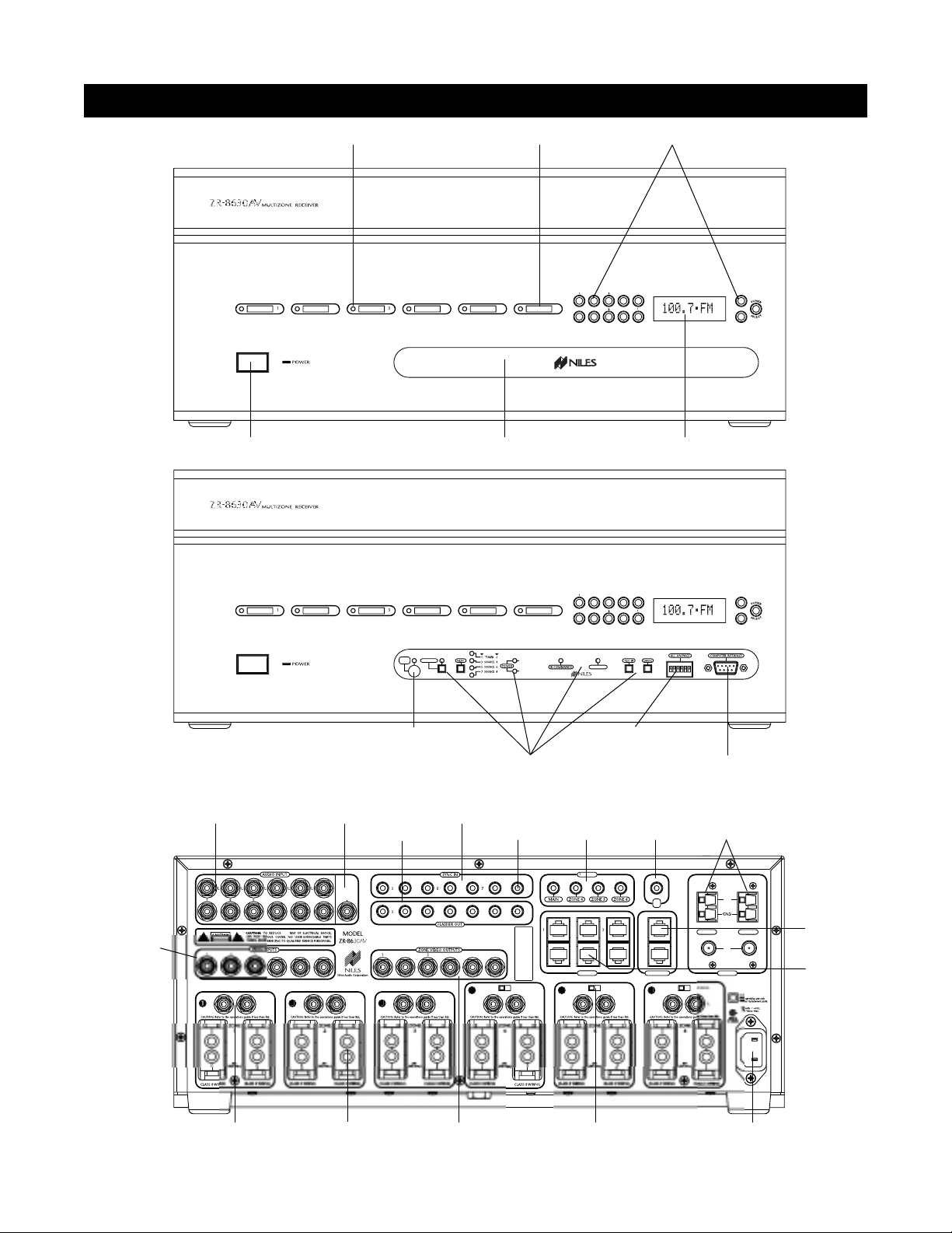
LED Zone ON/OFF Indicator Zone Label Slots T uner Controls
DB-9 Computer
Interface
Sensor for Capturing
IR Commands
Zone All On/Page
Enable Switches
Programming Controls
and Indicators
Tuner DisplayRemovable Programming CoverMain Power Switch
Video Inputs
Keypad Inputs
12V Sync
Inputs
Paging
Input
Flasher Outputs
IR
Input
12V Control
Outputs
Tuner Antenna
Inputs
Audio
Inputs
Individual Zone
Preamplifier Output
Removable
Speaker Connector
Removable
Power Cord Socket
Fixed/Variabl e Preamplifier
Adjustment Switch
Figure 1
System
Expansion
Zoned Video
Outputs
H.T. Sync
Input
Designed and Engineered in the USA. Made in Malaysia.
ENTE
PA
This device complies with part 15 of the FCC Rules. Operation is subject to the following two
conditions: (1) This device ma
interference received, including interference that may cause undesired operation
Miami, Florida US
3
P
I
not cause harmful interference, and (2) this device must accept an
ED LEDEEN LE
FIXEDVARIABL
POWER
DI
ETE "ON"
ETE "OFF"
DI
2V
EYPAD
FIXEDVARIABL
I
EXPANSI
FIXEDV
TUNE
TUNER
lensulat
Page 10

LED Zone ON/OFF Indicators
Provide individual ON/OFF indication for each zone.
Zone Label Slots
Coined slot for placing included zone labels for easy
identification.
Tuner Controls
Radio station up/down, radio station preset, and tuner
selection buttons.
Tuner Display
Displays the most recent tuner selected manually on the
front panel. Then that tuner displays the most recent station selected on that tuner. Also shown is the reception
mode (mono or stereo).
Removable Programming Cover
Conceals installer-only programming controls.
Main Power Switch
Turns the main power to the receiver ON and OFF.
Note: Equipment is not completely disconnected from the
main power source when power switch is in the OFF position.
Sensor for IR Capture
IR sensor captures IR commands that control the con-
nected source components.
Programming Controls and Indicators
Push buttons and LED prompts for system and IR pro-
gramming.
Zone ALL ON/PAGE Enable Switches
Individual DIP switches enable or disable system-wide
All ON commands and the paging feature.
DB-9 Computer Interface
Connects a laptop computer to back up and download pro-
gram configurations using ZR Source Library and Archiving
Software.
Sync Inputs
Video Inputs and Voltage Sync Inputs 3, 4, 5, 6, 7, and 8
detect when a source component is ON/OFF for reliable system activation. The HT mini-plug Sync Input senses voltage
for determining the ON/OFF status of a Home Theater system that shares source components with the ZR-8630AV.
Paging Input
A mono RCA input accepts a paging signal from a tele-
phone system.
Keypad Inputs
Six female RJ-45 jacks for connecting Master Keypad
Modules.
System Expansion
Two female RJ-45 jacks for connecting multiple receivers
together in larger multi-zone systems.
Flasher Outputs
Six 3.5mm jacks provide an output connection for
IRC-2P MicroFlashers
™
, one for each connected source
component. A seventh output labeled ALL is designed for
the IRC-1P High-Output IR Flasher.
IR Input
A single 3.5mm jack provides an input connection for IR
commands sent from a Home Theater system to control
source components shared with a ZR-8630AV.
12V Control Outputs
One 3.5mm jack controls source components requiring
activation from a switched AC outlet by providing a 12V
DC trigger signal for use with voltage-triggered AC power
strips (i.e., Niles AC-3). Three zone-specific 3.5mm jacks
(for zones 4, 5, and 6) activate external amplifiers that
may be specified for those zones by providing a 12V DC
trigger signal when the corresponding zone activates.
Tuner Antenna Inputs
Dual female coaxial F-connectors and spring-loaded,
bare-wire jacks provide connections for the included
AM and FM antennas, or external antennas.
Audio Inputs
Six pairs of stereo RCA jacks provide input connections
for source components.
Video Inputs
Six RCA jacks provide composite video input connections
for the distribution of audio/video source components.
Video Outputs
Six RCA jacks provide zoned output connections for TVs
and video displays.
Individual Zone Preamplifier Outputs
Six pairs of stereo RCA jacks provide output connections
for external amplifiers used instead of, or in conjunction
with, the built-in ZR-8630AV amplifiers.
Fixed/Variable Preamplifier-Output Adjustment Switch
Two-position switches for zones 4, 5, and 6 set
the individual preamplifier outputs to a variable or a
fixed signal.
Removable Speaker Connector
Niles’ patented no-strip speaker connector provides con-
nection to speakers in the listening zones.
Removable Power Cord
An IEC removable power cord provides easy handling dur-
ing installation.
10
PARTS GUIDE (ZR-8630AV)
Page 11
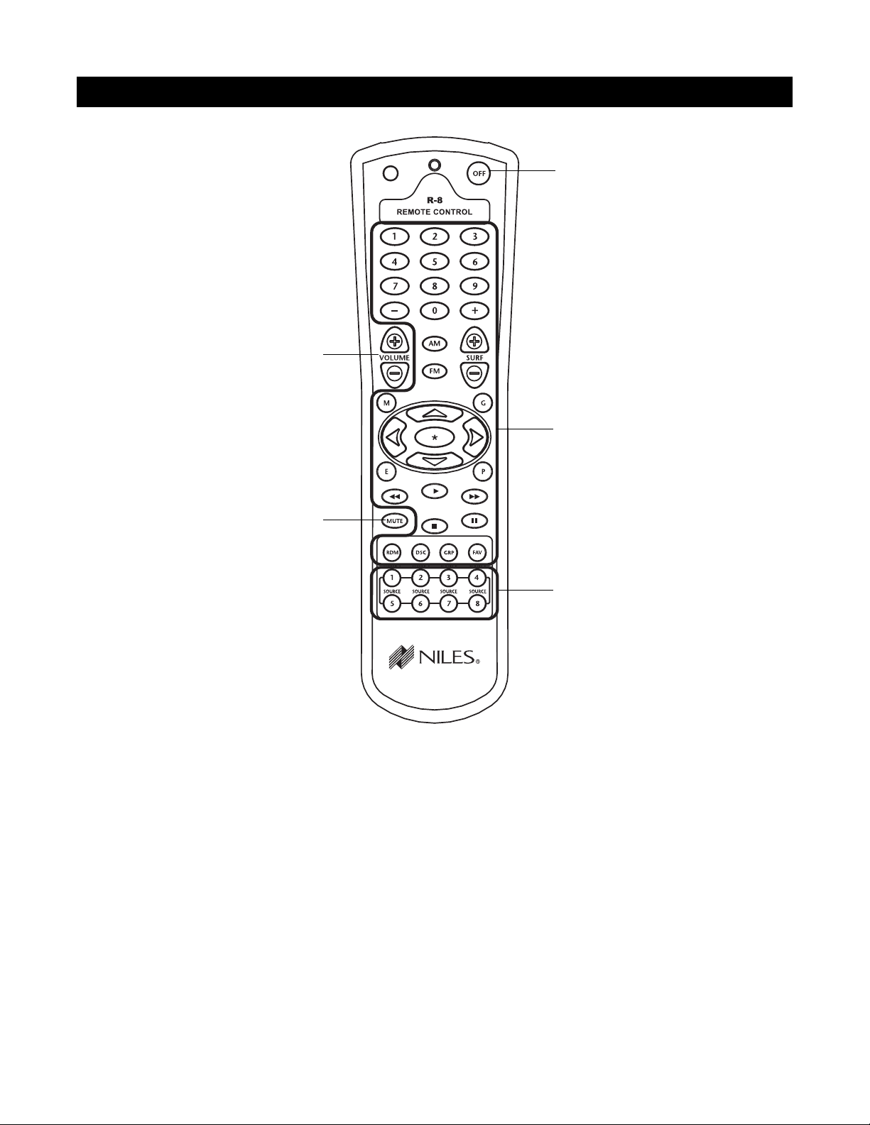
Source Buttons
Tap any of these buttons once to turn on the zone and
select a source component. Press and hold these buttons to turn on all enabled zones and select the same
source component in all zones.
Zone OFF Button
Tap this button once to turn OFF your specific zone.
Press and hold this button to turn OFF all zones.
Zone Volume Buttons
Press and hold these buttons to raise or lower the
volume in your specific zone, or to restore sound in a
muted zone.
Zone Mute Button
Tap this button once to mute the sound in a zone, or
to restore the sound in a muted zone.
Function Buttons
Press and hold these buttons to issue the individual IR
commands programmed to control the selected
source components.
11
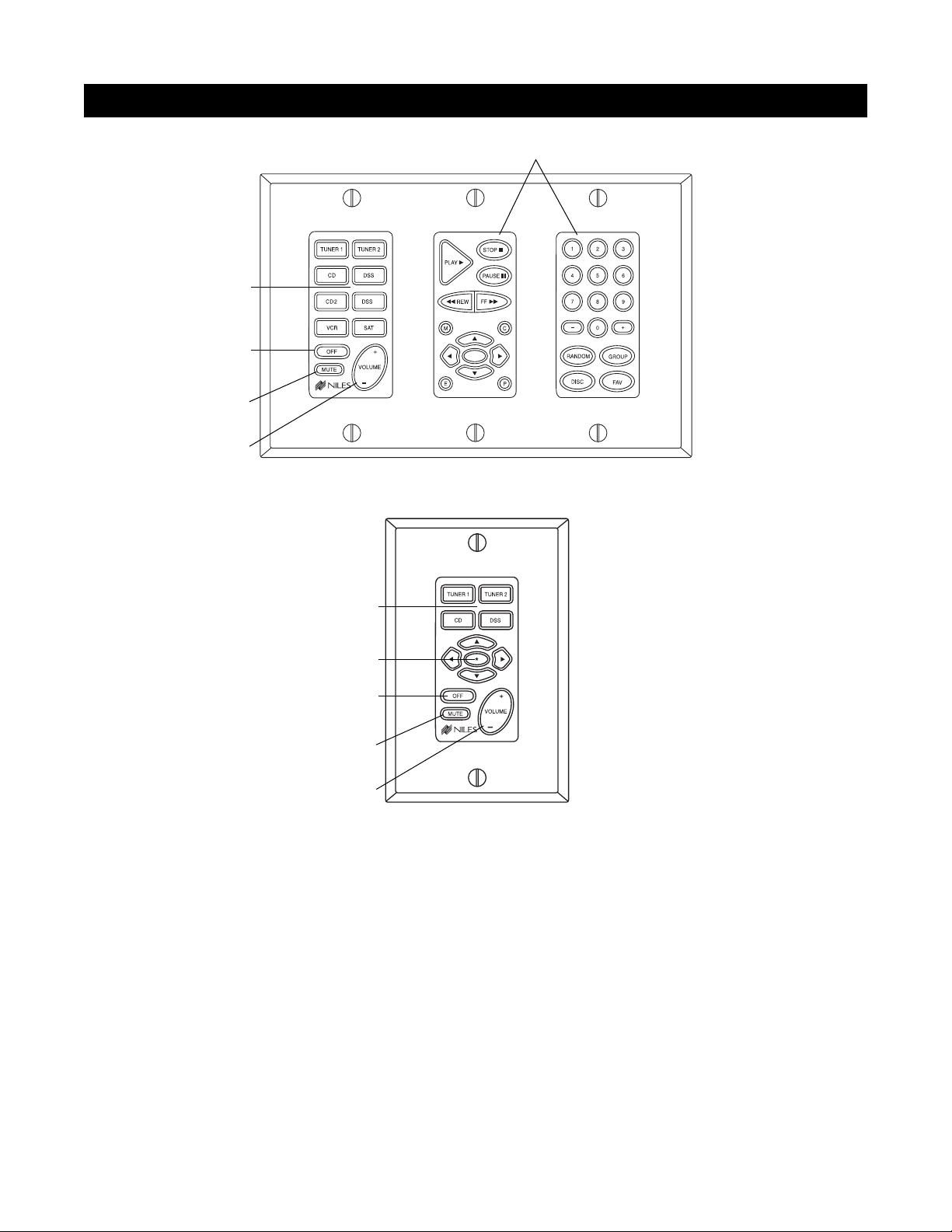
PARTS GUIDE (R-8 REMOTE) INCLUDED
Zone Volume Buttons
Zone OFF Button
Function Buttons
Source Buttons
Zone Mute Button
Figure 2
Page 12
12
PARTS GUIDE (INTELLIPAD®CI KEYPAD MODULES) SOLD SEPARATELY
Figure 3
Function Keys
Master Keys
Zone Off Key
Mute Key
Zone Volu me Key
Select™Master
Keypad Module
Transport™ Accessory
Keypad Module
Numeric™ Accessory
Keypad Module
Solo™ Master
Keypad Module
Master Keys
Function Keys
Mute Key
Zone Volu me Key
Zone Off Keys
NOTE: Select™and Solo™ Master Keypad Modules
with an integrated IR sensor are available. They
accept IR commands from the Niles R-8 Remote.
Master Keys
Tap any of these keys once to turn on the zone and
select a source component. Press and hold these keys
to turn on all enabled zones and select the same source
component in all zones.
Zone OFF Key
Tap this key once to turn OFF your specific zone. Press
and hold to turn OFF all zones.
Volume Keys
Press and hold these to raise or lower the volume in
your specific zone, or to restore sound in a muted zone.
Zone Mute Key
Tap this key once to mute the sound in a zone, or to
restore the sound in a muted zone.
Function Keys
Press and hold these keys to issue the individual IR
commands programmed to control the connected
source components.
*
Page 13
13
SYSTEM CONFIGURATIONS
Figure 4
O
1
3
6
6
T
GE
p
s
CONFIGURATION 1 - SIX ZONES
Source Components
AUDIO
DIGITAL
L
R
DIGITAL
CD CHANGER
AUDIO VIDEO
LR
DVD
Audio Cables
eaker Cable
S
DIGITAL
AUDIO
L
R
DIGITAL
DIGITAL
PA
AUDIO VIDEO
LR
DIGITAL
CD CHANGER
AUDIO VIDEO
LR
AUDIO VIDEO
LR
DSS
DVD
DSS
PHONE
PHONE
AC Power Cord
Switched
Niles
AC Outlet
AC-3
Unswitched
12V Trigger
Niles IRC-2P
MicroFlashers
H
AC Outlet
Speakers
S
E
E
R
N
A
S
R
O
F
R
N
I
T
K
U
N
O
O
K
C
ZONE 1
D
S
E
E
R
N
A
S
R
O
F
R
N
I
T
K
U
N
O
O
K
C
D
S
E
E
R
N
A
S
R
O
F
R
N
I
T
K
U
N
O
O
K
C
ZONE 2
D
S
E
E
R
N
A
S
R
O
F
R
N
I
T
K
U
N
O
O
K
C
D
S
E
E
R
N
A
S
R
O
F
R
N
I
T
K
U
N
O
O
K
C
ZONE 3
D
S
E
E
R
N
A
S
R
O
F
R
N
I
T
K
U
N
O
O
K
C
D
S
E
E
R
N
A
S
R
O
F
R
N
I
T
K
U
N
O
O
K
C
ZONE 4
D
S
E
E
R
N
A
S
R
O
F
R
N
I
T
K
U
N
O
O
K
C
D
S
E
E
R
N
A
S
R
O
F
R
N
I
T
K
U
N
O
O
K
C
ZONE 5
D
S
E
E
R
N
A
S
R
O
F
R
N
I
T
K
U
N
O
O
K
C
D
D
S
S
E
E
E
E
R
R
N
N
A
A
S
S
R
R
O
O
F
F
R
R
N
N
I
I
T
T
K
K
U
U
N
N
O
O
O
O
K
K
C
C
ZONE 6
D
TVTVTV
NE
Z
ZONE 2 ZONE
ZONE 4 ZONE 5 ZONE
Keypads
Page 14

INTRODUCTION TO ZR-8630AV CONFIGURATIONS
The Niles ZR-8630AV Audio/Video MultiZone Receiver combines with source components and control
devices (keypads, remote controls, and IR sensors) to deliver audio and video to multiple zones throughout a
home. This section of the manual describes 12 different ways to configure a ZR-8630AV system, beginning
with the most basic (Configuration 1). Possible variations from the basic configuration include enlarging the
system with additional ZR-8630AV units; expansion of zones and listening areas; and integration of a Home
Theater, external amplifiers, and an IR repeating system.
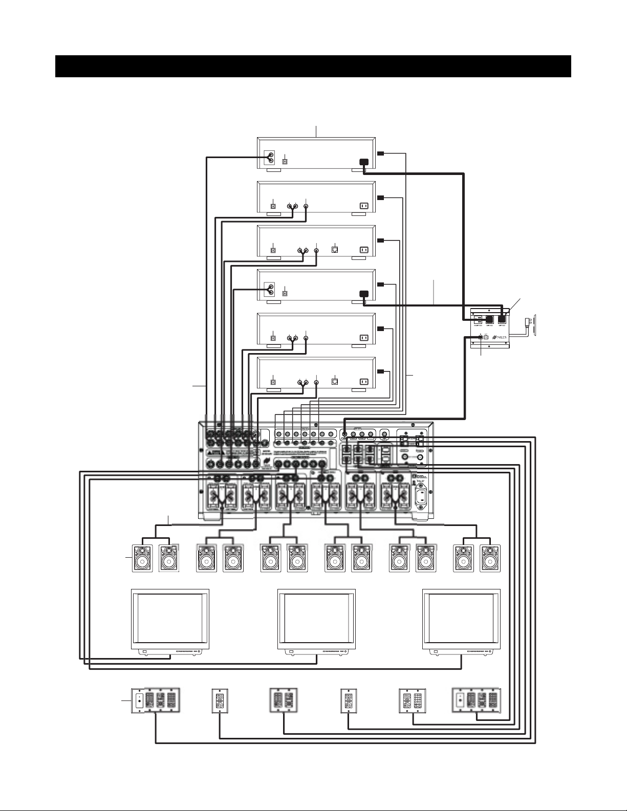
CONFIGURATION 1 - SIX ZONES
Figure 4 depicts the most basic configuration, in which one Niles ZR-8630AV Audio/Video MultiZone Receiver
and six separate components (which can be audio or audio/video) provide sound (with or without video) to six
listening zones. Each zone consists of one room with a pair of speakers. In Figure 4, three zones also have TV sets,
though the system could accommodate video in all six zones.
For user control, each zone includes a Select
™
or Solo™Master Keypad Module. (These devices are available with or
without a built-in IR sensor.) In addition, some zones in Figure 4 have optional Numeric
™
and/or Transport™ Accessory
Keypad Modules and a separate IR sensor. Jumper cables (included) connect the Accessory Keypad Modules and separate IR sensor to the Master Keypad Module. Use any combination of control devices to provide the desired degree
of control in a given zone, with two exceptions: the Select
™
and Transport™cannot mate with the the Solo™.
Source Components
The ZR-8630AV has RCA audio/video inputs for connecting six external source components. Each of the six
listening zones can select from among the six source components, and the two built-in AM/FM tuners.
With this configuration, a user in one zone can listen to and view one source component while another user in
a different zone listens to and views a different source component (i.e., the DVD can be selected in Zone 1 while
the tuner is selected in Zone 2). Additionally, each of the six zones can be set to an individual volume level. If
more than one zone chooses the same source component, they share IR control of that source component.
Keypads, IR Sensors, and Remote Controls
Keypads, IR sensors, and remote controls enable users to control the Niles ZR-8630AV Audio/Video MultiZone
Receiver and connected source components by issuing source-component IR commands programmed into the
ZR-8630AV. To trigger these commands, a user presses a keypad key or remote-control button.
The Select
™
or Solo™Master Keypad Module in each zone connects to the ZR-8630AV through a “home run”
of four-pair twisted cable terminating in an RJ-45 connector. Each Select
™
and Select
™
IR Master Keypad Module
can mate with an optional Transport
™
and/or Numeric™Accessory Keypad Module. The Solo™and Solo™ IR can
mate with the Numeric
™
but not the Transport™. Jumper cables for these connections are included. (See
Connections, Figure 33.)
Adding an IR sensor enables the Niles R-8 Remote to control the ZR-8630AV and the connected source com-
ponents from anywhere in a sensor-equipped room. Master Keypad Modules are available with a built-in
narrow-bandwidth IR sensor that works only with the R-8. In addition, or as an alternative, any zone can
include a separate wide-bandwidth IR sensor that connects directly to a Master Keypad Module. Widebandwidth sensors work with the R-8 and factory remotes from a wide variety of source components. For separate IR sensors, installed with two-conductor shielded cable rather than four-pair twisted cable, Niles offers a
three-wire to RJ-45 adapter. (See the Installation and Accessories sections of this manual for more details.)
14
SYSTEM CONFIGURATIONS
Page 15

In a very large room, you may want to provide a separate IR sensor across the room from a Select™ IR or Solo
™
IR Master Keypad Module.
With a separate IR sensor, a source component's actual IR commands (i.e., provided by the component's
original remote control or a learning remote control programmed with these IR commands) will control the
source components.
Important Note: The ZR-8630AV does not provide individual operation of identical source components when
using a source component's factory remote through an IR sensor. (See Identical Source Components on page
43 for more details.)
Source-Component Automation
There are two methods of managing the power ON/OFF of the source components.
1.
Synchronized IR - In Figure 4, a video signal connected to the ZR-8630AV synchronizes the DSS receiver’s
power ON/OFF. When the Master Key/Source Button for the DSS is pressed, the ZR-8630AV checks for a
video signal at the Sync Input corresponding to the DSS.
The ZR-8630AV issues the power command to turn
the DSS ON only when no video signal is present and the DSS is OFF.
When the Off Key/Button is pressed in a zone, the ZR-8630AV checks to see if any other zones are ON
(including the Home Theater Zone sharing sources). The power command for turning the DSS OFF is issued
only if that zone is the last zone turning OFF in entire system and a video signal is present at the Sync Input
corresponding to the DSS.
Important Note: 12V Sync Inputs can detect 12V for use with Niles external sensing devices, (i.e. the LS-1 Light
Sensor and the APC-2 Current Sensing Device). See Connections on page 46 for more information.
2.
Latching Power - In Figure 4, the switched AC outlets of a Niles AC-3 AC turn power to the DVD and CD
changer on and off. The 12V Control Output from the ZR-8630AV activates the AC-3 when any of the six
zones is ON (including the Home Theater Zone sharing sources). The built-in AM/FM tuners also turn ON
when any of the six zones is ON.
Each Master Key on the Master Keypad Module and its respective source component are programmable with a
sequence of IR commands. Commands included in the sequence typically are the Play or Channel commands to
start a source playing or to select a particular music or radio station after the source has been selected.
Flasher Outputs
Niles IRC-2P MicroFlashers™connect to the numbered flasher outputs on the rear panel of the Niles ZR-8630AV.
Flashers send IR commands to the individual source components for control. To control more than one source
component, connect an IRC-1P Flooding Flasher to the Flasher output labeled ALL .
Video Outputs
Each zone has “home run” RG-6 coaxial cable with 100-percent quad-shielding from the video output to a TV
set or other video-display device located in the zone. To avoid video-signal degradation, such runs should not
exceed 500 feet (152 meters).
Speakers
“Home run” speaker cables from the speakers in each zone connect to the built-in zone amplifier. Connections to the ZR-
8630AV unit’s speaker output terminals employ Niles’ patented no-strip speaker connectors.
15
SYSTEM CONFIGURATIONS
Page 16
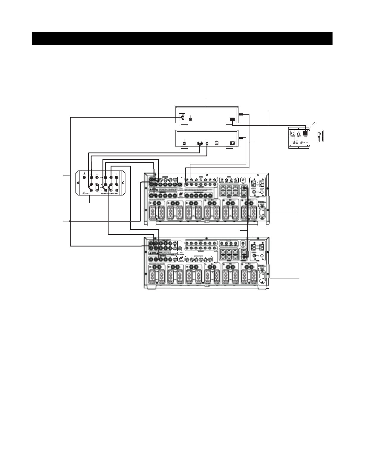
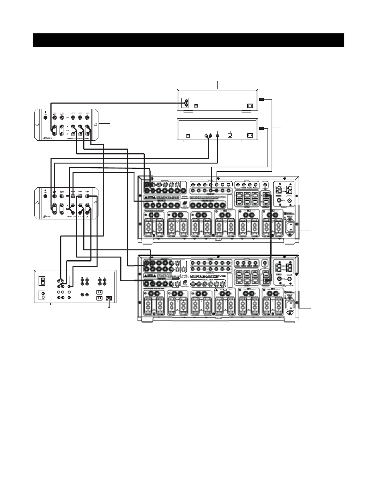
CONFIGURATION 2 – ADDING ZONES USING MULTIPLE ZR-8630AV UNITS
If the system requires more than six zones, use more than one ZR-8630AV to create a larger multi-zone/multi-
source system. You can combine as many as three ZR-8630AV units to provide up to 18 zones. Designate one
ZR-8630AV as the Master and the others as Slaves. (See Installation Settings on page 60 for more details.)
In Figure 5, a four-pair twisted cable connecting the expansion ports of the two ZR-8630AV units facilitates
communication between them, allowing all zones provided by both ZR-8630AV units to obtain control of the
shared source components (which are always connected to the Master). Also, any zone can issue systemwide commands (i.e. All Zones ON/OFF).
Sharing Source Components with Two ZR-8630AV Units
Two Niles ZR-8630AV Audio/Video MultiZone Receivers (Figure 5) share the audio and video signals from the
source components. Connect the audio and video signals to both ZR-8630AV units. To make these connections, RCA Y-adapters are acceptable for sharing audio signals, but sharing video signals requires a Niles
AVDA-3 Audio/Video Distribution Amplifier.
Note: When sharing source components with a third ZR-8630AV (for an 18-zone system) or with a Home
Theater system, refer to Configuration 3.
The programming in the master ZR-8630AV accomplishes source-component control (Figure 6). Leave all Slave
ZR-8630AV units in the system unprogrammed except for tuner preset stations. Make all Flasher and Sync Input
connections for the shared source components to the Master ZR-8630AV. Keypad/Button commands and Zone
ON/OFF status are communicated to the Master ZR-8630AV through the System Expansion In/Out connections, providing coordinated control of all source components.
GE
y
y
.
A
2
GE
,
A
16
Figure 5
SYSTEM CONFIGURATIONS
Designated
as the Master
Designated
as Slave #1
Source Components
Audio Cables
udio Cables with
RCA Y Adapters
Niles AVDA-3
Distribution Amplifier
AUDIO
PA
PA
LECTRICAL SHOCK
Miami, Florida US
DIGITAL
L
CD CHANGER
R
DIGITAL
AUDIO VIDEO
LR
This device complies with part 15 of the FCC Rules. Operation is subject to the following two
not cause harmful interference, and (2) this device must accept an
conditions: (1) This device ma
interference received, including interference that may cause undesired operation
DSS
PHONE
Four Pair Twisted Cable
VA
AC Power Cord
Niles IRC-2P
MicroFlashers
TUNER 2
TUNER
Switched
Niles
AC Outlet
AC-3
12V Trigger
Unswitched
AC Outlet
Page 17
17
SYSTEM CONFIGURATIONS
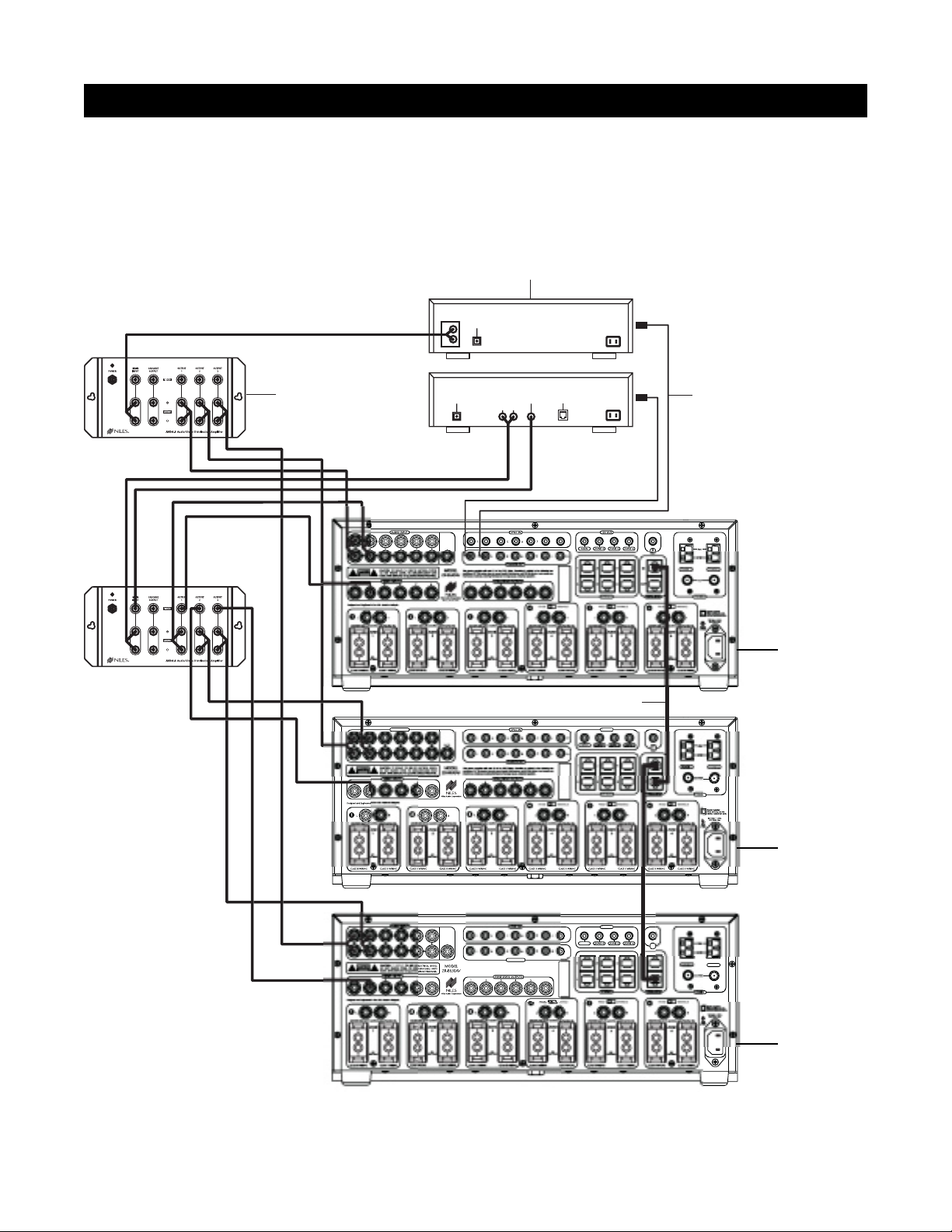
CONFIGURATION 3 – DISTRIBUTING SOURCE-COMPONENT AUDIO AND VIDEO SIGNALS
When sharing source components with three ZR-8630AV units (see Figure 6) or two ZR-8630AV units and a
Home Theater system (see Figure 7), each source—whether audio or video—requires a Niles AVDA-3
Audio/Video Distribution Amplifier.
GE
A
OUT
UT
S
R
y
y
.
A
OUT
2
GE
OUT
Niles IRC-2P
MicroFlashers
Source Components
Niles AVDA-3
Distribution Amplifier
LR
AUDIO VIDEO
DSS
PHONE
DIGITAL
L
CD CHANGER
R
AUDIO
DIGITAL
Figure 6
Designated
as the Master
Designated
as Slave #1
Designated
as Slave #2
AUDIO INP
PA
Miami, Florida US
PA
Miami, Florida US
Four-Pair Twisted Cable
FLASHER
This device complies with part 15 of the FCC Rules. Operation is subject to the following two
conditions: (1) This device ma
not cause harmful interference, and (2) this device must accept an
interference received, including interference that may cause undesired operation
H
2V
2V
I
TUNER
Page 18
18
CONFIGURATION 3 – DISTRIBUTING SOURCE-COMPONENT AUDIO AND VIDEO SIGNALS
An AVDA-3 can send video to a maximum of three destinations. If you install three ZR-8630AV units with an
integrated Home Theater Zone (refer to Figure 8), you may connect the cascade output on each AVDA-3 to the
third ZR-8630AV. If a video component has only one composite-video output, look for an S-video or componentvideo output (if applicable to the Home Theater). If a video component has two composite-video outlets, connect
one to the Home Theater and the other to an AVDA-3 for distribution to the three ZR-8630AV units. If neither of
those solutions yields suitable results, install two AVDA-3 units per video component.
Important Note: An AVDA-3 is required whenever you share source components with a Home Theater receiv-
er that shorts its audio inputs. (Some Home Theater receivers short their audio inputs when their power is off
or the input is not currently selected.)
SYSTEM CONFIGURATIONS
2
A
2
GE
Figure 7
Designated
as the Master
Designated
as Slave #1
Source Components
AUDIO
DIGITAL
L
R
CD CHANGER
DIGITAL
1
2
CD
L
R
Video 1
Video 2
Niles AVDA-3
Distribution Amplifier
DIGITAL
DSS
AUDIO VIDEO
LR
PHONE
Niles IRC-2P
MicroFlashers
TUNER
Four Pair Twisted Cable
PA
AUDIO
VIDEO
FRONT
LR
CD
DSS
L
R
CENTER
SURROUND
L
R
Miami, Florida US
VA
TUNER
Home Theater Receiver
Page 19
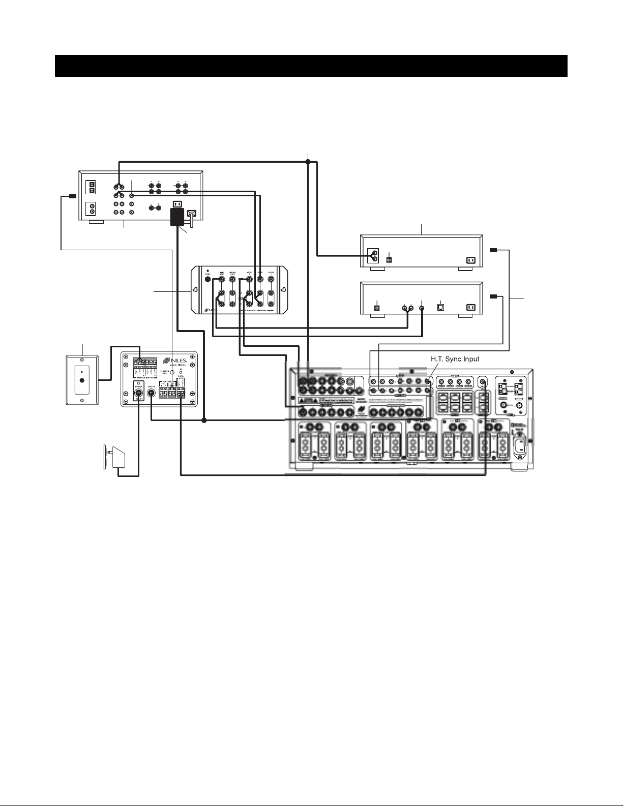
CONFIGURATION 4 – INTEGRATING AN IR-CONTROLLED HOME THEATER
An IR-controlled Home Theater surround-sound receiver can be integrated to share source components in a
system with the ZR-8630AV.
Distributing Audio and Video Signals
Connect the audio and video signals for the shared source components to both the ZR-8630AV and the Home
Theater receiver (Figure 8). To make these connections, RCA Y-adapters are acceptable for sharing audio signals, but sharing video signals requires a Niles AVDA-3 Audio/Video Distribution Amplifier.
Important Note: If the Home Theater Receiver has shorting audio inputs, use a Niles AVDA-3 Distribution
Amplifier in place of the RCA Y-adapters (refer to Figure 7).
Shared Source-Component Control
Connect the DATA output from the Home Theater IR repeater (Figure 8) to the IR Input of the ZR-8630AV. The
Home Theater IR remote control now can control the shared source components.
A 12V Sync signal from the Home Theater to the Home Theater Sync Input informs the ZR-8630AV about the
ON/OFF status of the Home Theater, enabling the ZR-8630AV to coordinate control of the shared source component's power ON/OFF.
Important Note: When issuing the source component’s actual IR commands from the Home Theater remote
control, all IR commands pass through to all source-component flasher outputs. Identical brand and model
source components cannot operate individually using these commands. (For more information on controlling
identical brand and model source components, refer to the Operational Overview on page 34.)
19
SYSTEM CONFIGURATIONS
2
GE
Figure 8
Audio Cables with RCA Y-Adapters
DIGITAL
AUDIOCDVIDEO
LR
1
CD
2
DSS
Video 1
L
R
Video 2
Home Theater Receiver
FRONT
L
R
CENTER
REAR
L
R
12V
D.C.
Plugged into
Switched
AC outlet
Source Components
AUDIO
DIGITAL
L
R
CD CHANGER
Distribution Amplifier
Niles IR Sensor
located in
Home Theater
Plugged into
Unswitched
AC outlet
Niles AVDA-3
12V
D.C.
Niles
IRP2+
DIGITAL
PA
DSS
AUDIO VIDEO
LR
PHONE
Niles IRC-2P
MicroFlashers
TUNER
Page 20
20
SYSTEM CONFIGURATIONS
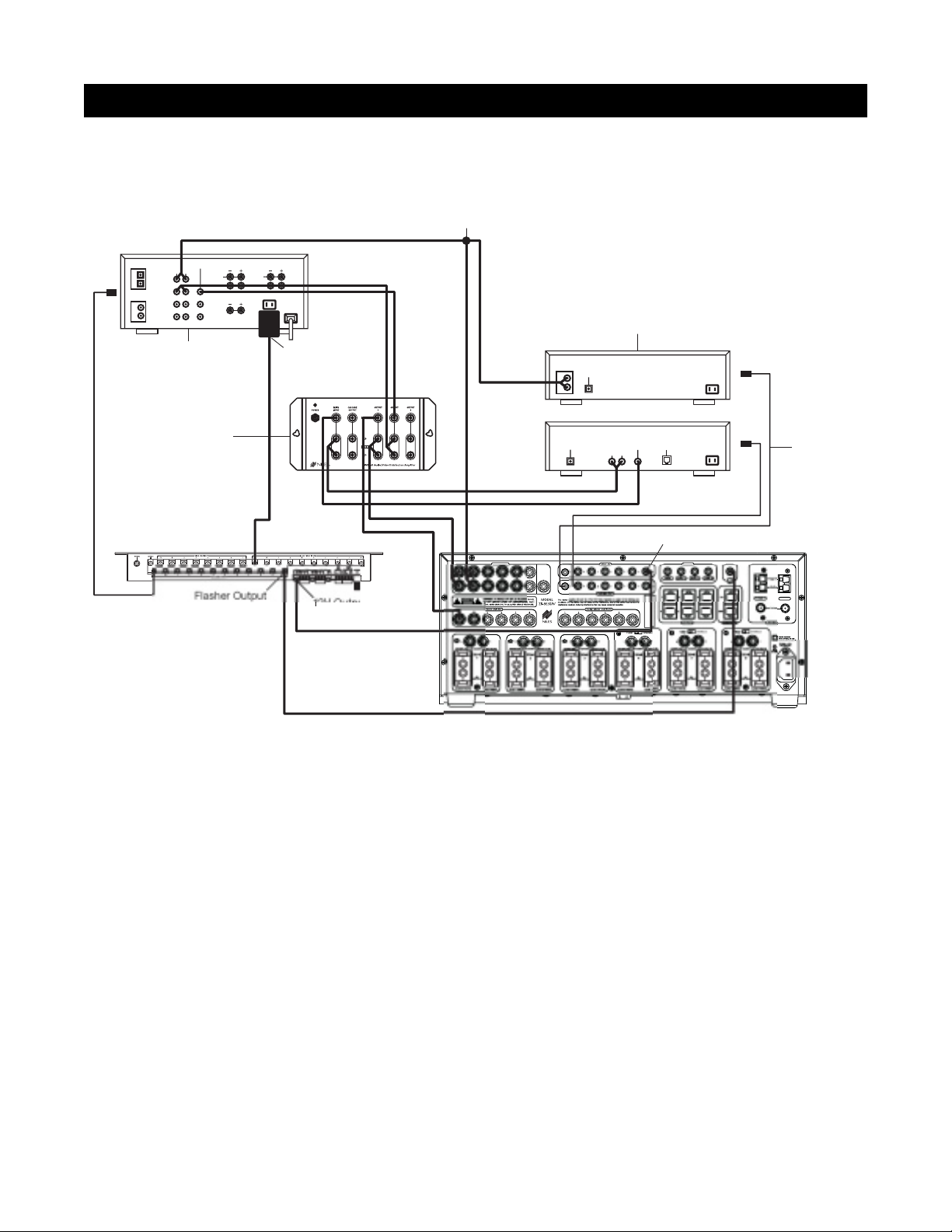
CONFIGURATION 5 – INTEGRATING A HOME THEATER USING AN INTELLICONTROL
®
A Home Theater system controlled by a Niles IntelliControl®can be integrated to share source components in
a system with the ZR-8630AV.
Distributing Audio and Video Signals
Connect the audio and video signals for the shared source components to both the ZR-8630AV and the Home
Theater receiver (Figure 8). To make these connections, RCA Y-adapters are acceptable for sharing audio signals, but sharing video signals requires a Niles AVDA-3 Audio/Video Distribution Amplifier.
Important Note: If the Home Theater Receiver has shorting audio inputs, use a Niles AVDA-3 Distribution
Amplifier in place of the RCA Y-adapters. (For more information, see Configuration 3.)
Shared Source-Component Control
Connect the flasher output from the IntelliControl®(Figure 9) to the IR Input of the ZR-8630AV. Now the
IntelliControl, programmed with Niles R-8 Remote IR commands, can automate and control the shared source
components. Teach Niles R-8 IR commands to the IntelliControl using the R-8 Remote. (See Programming
Overview for more details.)
A 12V Sync signal from the Home Theater to the Home Theater Sync Input informs the ZR-8630AV about the
ON/OFF status of the Home Theater, enabling the ZR-8630AV to coordinate control of the shared source component's power ON/OFF.
Important Note: When issuing the source component’s actual IR commands from the Home Theater remote
control, all IR commands pass through to all source-component flasher outputs. Identical brand and model
source components cannot operate individually using these commands. (For more information on controlling
identical brand and model source components, refer to the Operation Overview on page 34.)
n
A
2
GE
SU
t
Figure 9
Audio Cables with RCA Y-Adapters
DIGITAL
AUDIOCDVIDEO
LR
1
CD
2
DSS
Video 1
L
R
Video 2
L
R
Home Theater Receiver
Niles AVDA-3
Distribution Amplifier
IntelliControl M
FRONT
CENTER
REAR
L
R
12V
D.C.
Plugged into
Switched
AC outlet
PA
Niles Audio Corporatio
Miami, Florida US
Source Components
AUDIO
DIGITAL
L
R
DIGITAL
CD CHANGER
AUDIO VIDEO
LR
DSS
PHONE
H.T. Sync Inpu
Niles IRC-2P
MicroFlashers
TUNER
Page 21
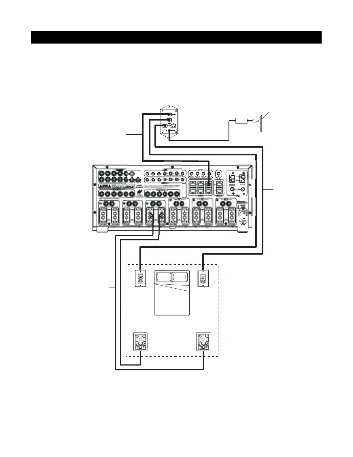
CONFIGURATION 6 – MULTIPLE MASTER KEYPAD MODULES IN A ZONE
You can expand the single zone of a Niles ZR-8630AV Audio/Video MultiZone Receiver to contain multiple
Master Keypad Modules, providing control from many locations within the zone. Use a Niles IntelliPad
®
Ci
Expander
™
to connect multiple keypads in a single zone. By using two Expanders, you can include up to five
Master Keypad Modules in a single zone.
Within a zone, you can use Solo
™
and/or Select™Master Keypad Modules in any combination. All connected keypads in a zone work in tandem (i.e., all control the same zone and display the same Zone ON/OFF, Mute, and
Input Select Status), except that Solo
™
keypads cannot activate or display the status of sources 5, 6, 7, and 8
because they have only four Master Keys. Activation of these sources in a zone equipped with Solo
™
keypads
simultaneously lights up their Master Keys 3 and 4. In Figure 10, a Select
™
Master Keypad Module is installed on
each side of a bed.
21
SYSTEM CONFIGURATIONS
R
2
GE
es
Figure 10
IntelliPad® Ci Expander
™
Unswitched
AC Outlet
Tw isted Cable
Tw o-Conductor
Speaker Cable
Four-Pair
Power
Supply
PA
I
TUNER
Four-Pair
Tw isted Cable
Keypads
Bed
ZONE 3
(Bedroom)
C
K
O
O
N
U
K
T
I
N
R
F
O
R
S
A
N
R
E
E
S
D
C
K
O
O
N
U
K
T
I
N
R
F
O
R
S
A
N
R
E
E
S
D
Speakers
Page 22
22
SYSTEM CONFIGURATIONS
CONFIGURATION 7 – MULTIPLE LISTENING AREAS IN A ZONE
You can set up a single zone of the ZR-8630AV to contain more than one listening area (i.e., an adjacent liv-
ing room and dining room). Choose this configuration when the speakers in the zone need not play at separate volume levels or be ON/OFF separately.
In Figure 11, speaker cable connects to the speaker outputs of Zone 3 and then parallel-connects to the
speakers in both the living room and dining room. Each area has a Master Keypad Module. Use a Niles
IntelliPad
®
Ci Expander™to connect the two Master Keypad Modules in a single zone. All connected keypads
in a zone work in tandem (i.e., all control the same zone and display the same Zone ON/OFF, Mute, and Input
Select Status).
Within a zone, you can use Master Keypad Modules in any combination. All connected keypads in a zone work
in tandem (i.e., all control the same zone and display the same Zone ON/OFF, Mute, and Input Select Status),
except that Solo
™
and Solo™IR keypads cannot activate or display the status of sources 5, 6, 7, and 8 because they
have only four Master Keys. Activation of these sources in a zone equipped with Solo
™
or Solo™IR keypads simul-
taneously lights up their Master Keys 3 and 4.
You can add one or two pairs of 8-ohm speakers to a zone in this manner. For zones with more than two pairs
of speakers, an external amplifier is necessary.
R
2
GE
Figure 11
Niles
IntelliPad
®
Ci Expander
™
Unswitched
AC Outlet
Tw o-Conductor
Speaker Cable
Four-Pair
Tw isted Cable
3
PA
ZONE 3
(Living / Dining Room)
Living Room Dining Room
Power
Supply
I
TUNER
Four-Pair
Tw isted Cable
Keypads
C
K
O
O
N
U
K
T
I
N
R
F
O
R
S
A
N
R
E
E
S
D
C
K
O
O
N
U
K
T
I
N
R
F
O
R
S
A
N
R
E
E
S
D
C
K
O
O
N
U
K
T
I
N
R
F
O
R
S
A
N
R
E
E
S
D
C
K
O
O
N
U
K
T
I
N
R
F
O
R
S
A
N
R
E
E
S
D
Speakers
Page 23
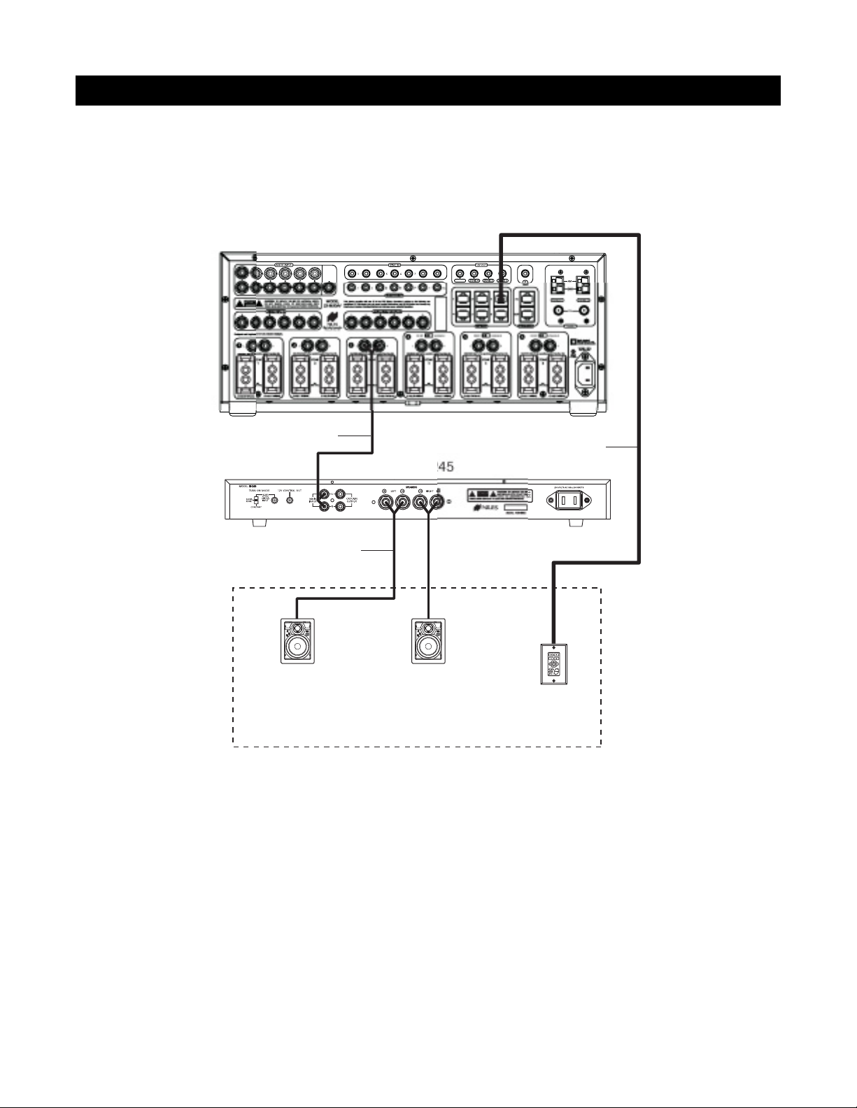
CONFIGURATION 8 – EXTERNAL AMPLIFIER IN A ZONE FOR MORE POWER
To provide more power in a zone, use an external amplifier. An RCA preamplifier output connection for each
zone of the ZR-8630AV allows you to connect external amplifiers for zones requiring additional power.
In Figure 12, an external amplifier has been connected to zone 3. Using an amplifier with more than 30W per
channel provides the zone with more volume for listening in large rooms and outdoors.
Important Note: When using preamplifier outputs in this configuration for zones 4, 5, and 6, set the fixed/vari-
able switch in the variable position.
23
SYSTEM CONFIGURATIONS
GE
s
2
Figure 12
PA
RCA Audio Cable
Four-Pair Twisted Cable
Niles SI-
Tw o-Conductor
Speaker Cable
D
S
E
E
R
N
A
S
R
O
F
R
N
I
T
K
U
N
O
O
K
C
Speakers
D
S
E
E
R
N
A
S
R
O
F
R
N
I
T
K
U
N
O
O
K
C
Keypad
ZONE 3
Page 24
24
SYSTEM CONFIGURATIONS
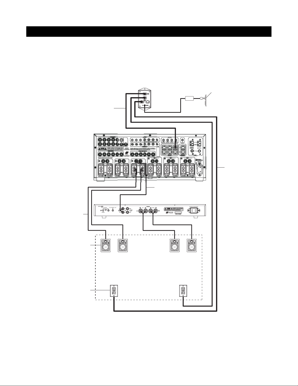
CONFIGURATION 9 – EXTERNAL AMPLIFIER IN A ZONE FOR MULTIPLE LISTENING AREAS
You can set up a zone of the ZR-8630AV to contain more than one listening area by adding an external ampli-
fier (i.e., an adjacent living room and dining room area). Choose this configuration when the speakers in the
zone need not play at separate volume levels or be on/off separately.
In Figure 13, an external amplifier connects to Zone 3. This enables the zone to have an additional listening area
with its own dedicated amplifier. Now, with the internal amplifier of the ZR-8630AV dedicated to one listening
area and the external amplifier to the other, the speakers in both areas receive more power.
Important Note: When using preamplifier outputs in this configuration for zones 4, 5, and 6, set the fixed/vari-
able switch in the variable position.
GE
S
s
5
Figure 13
Niles
Ci Expander
Unswitched
AC Outlet
Tw o-Conductor
Speaker Cable
Speakers
Four-Pair
Tw isted Cable
D
S
E
E
R
N
A
S
R
O
F
R
N
I
T
K
U
N
O
O
K
C
PA
D
S
E
E
R
N
A
S
R
O
F
R
N
I
T
K
U
N
O
O
K
C
Niles SI-24
RCA Audio Cable
Power
Supply
TUNER 2
Four-Pair
Twisted Cable
D
S
E
E
R
N
A
S
R
O
F
R
N
I
T
K
U
N
O
O
K
C
D
S
E
E
R
N
A
S
R
O
F
R
N
I
T
K
U
N
O
O
K
C
Living Room
Dining Room
ZONE 3
(Living / Dining Room)
Keypads
Page 25
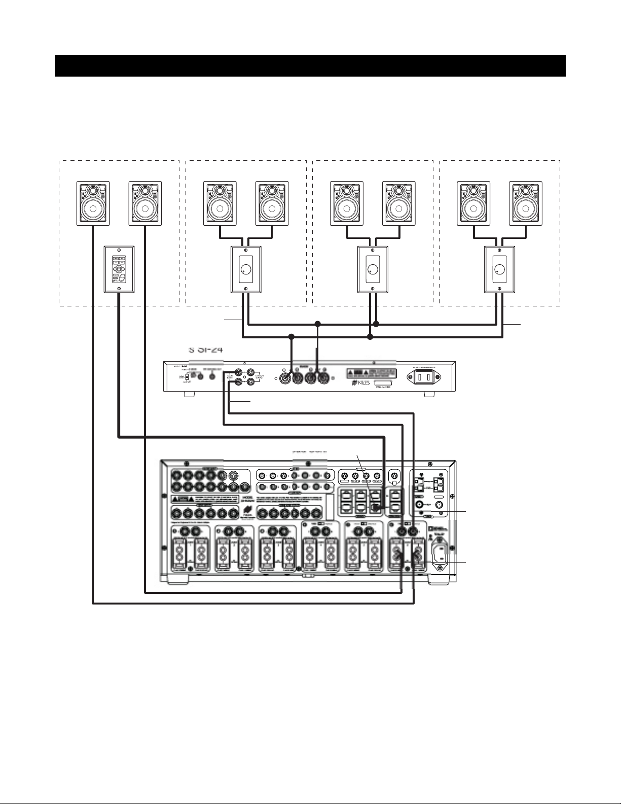
CONFIGURATION 10 – EXTERNAL AMPLIFIER IN A ZONE FOR MULTIPLE ROOMS
The preamplifier output connectors on the ZR-8630AV for zones 4, 5 and 6 have a fixed/variable setting. Use
the fixed setting with an external amplifier to divide a zone into individual rooms using conventional Niles
impedance-matching volume controls.
In Figure 14, Zone 6 has been expanded into four rooms. Each room can be ON/OFF individually and be set
at a different volume level.
The speakers for the master bedroom connect to the internal zone amplifier of the ZR-8630AV. A Select
™
Master
Keypad Module in the master bedroom controls ON/OFF, source selection, and source operation for the entire
zone. However, the volume and mute buttons on the Select
™
Master Keypad Module affect only the speakers
in the master bedroom.
Impedance-magnifying volume controls allow individual control of the speakers connected to the external
zone amplifier in the master bathroom, the walk-in closet, and the terrace.
25
SYSTEM CONFIGURATIONS
R
2
GE
s
Figure 14
Master Bedroom Master Bathroom Walk-In Closet Terrace
D
S
E
E
R
N
A
S
R
O
F
R
N
I
T
K
U
N
O
O
K
C
D
S
E
E
R
N
A
S
R
O
F
R
N
I
T
K
U
N
O
O
K
C
Speaker Cable
D
S
E
E
R
N
A
S
R
O
F
R
N
I
T
K
U
N
O
O
K
C
D
S
E
E
R
N
A
S
R
O
F
R
N
I
T
K
U
N
O
O
K
C
D
S
E
E
R
N
A
S
R
O
F
R
N
I
T
K
U
N
O
O
K
C
D
S
E
E
R
N
A
S
R
O
F
R
N
I
T
K
U
N
O
O
K
C
D
S
E
E
R
N
A
S
R
O
F
R
N
I
T
K
U
N
O
O
K
C
D
S
E
E
R
N
A
S
R
O
F
R
N
I
T
K
U
N
O
O
K
C
Wired in
Parallel
ZONE 6
RCA Audio Cable
PA
I
TUNER
Preamplifier set
to Fixed Mode
Variable Speaker Output
Page 26
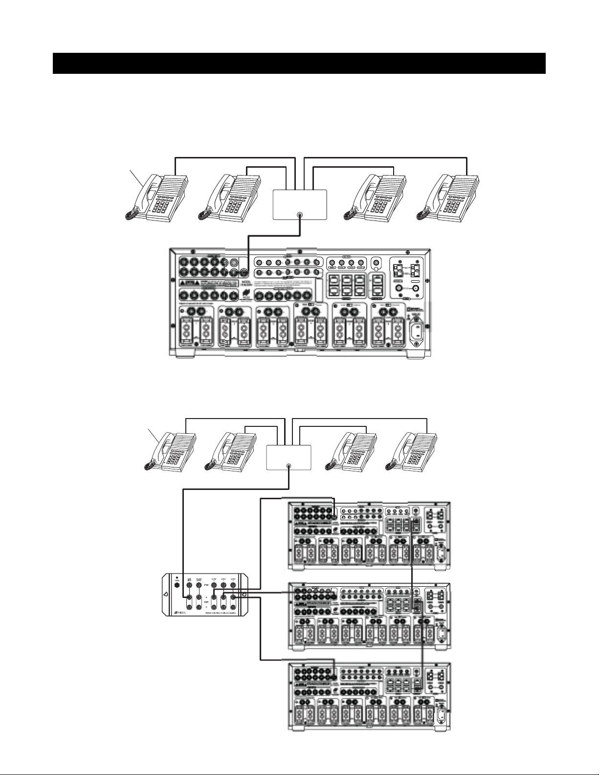
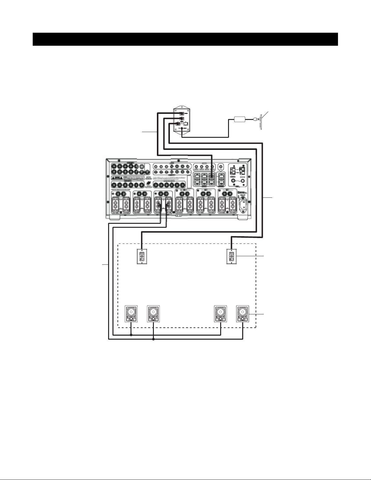
CONFIGURATION 11 – SYSTEM PAGING AND EXTERNAL TELEPHONE SYSTEM
For voice paging through the speakers in the listening zones (see Figure 15), a Paging Input connection on the rear panel
of the ZR-8630AV accepts the paging output signal of popular telephone systems. You can adjust the paging volume
level in the ZR-8630AV. (See Installation Settings on page 61 for more information.)
Use a Niles AVDA-3 (see Figure 16) when connecting a telephone system to more than one ZR-8630AV in
larger systems.
SYSTEM CONFIGURATIONS
R
2
GE
Figure 15
Figure 16
26
System
Telephones
Te lephone
Control Unit
PAGE OUTPUT
PA
I
TUNER
System
Telephones
Telephone
Control Unit
PAGE OUTPUT
Niles AVDA-3
Distribution Amplifier
Page 27

CONFIGURATION 12 – IR REPEATING FOR CONTROL OF LOCAL COMPONENTS
You can integrate an IR Repeating System into a room connected to the Niles ZR-8630AV (see Figure 17). This
enables a single IR Sensor (installed in that room) to control local components with a hand-held IR remote control.
In Figure 17, a Niles IR Sensor connects to a Niles IRP-6+ for control of local components, and to a Niles
ZR-8630AV for control of distributed components. When the local system is activated, a Niles SPK-1 Automated
Speaker Level A-B Switcher switches the front speakers in the master bedroom from the ZR-8630AV distributedsound system to the local surround-sound receiver system.
Important Note: This configuration does not support the use of an identical brand and type component in both
the local and the distributed system (i.e., a Sony CD player in both systems). Individual operation of identical
components may not be possible. To prevent IR feedback when using this configuration, you may need the IR
blockers included with Niles IRC-2 MicroSensors
™
.
27
SYSTEM CONFIGURATIONS
Figure 17
Zone 6 – Master Bedroom
Center
Left
Front
D
S
E
E
R
N
A
S
R
O
F
R
N
I
T
K
U
N
O
O
K
C
D
S
E
E
R
N
A
S
R
O
F
R
N
I
T
K
U
N
O
O
K
C
D
S
E
E
R
N
A
S
R
O
F
R
N
I
T
K
U
N
O
O
K
C
Niles SPK-1
Right
Front
Unswitched
AC Outlet
Power
Supply
D
S
E
E
R
N
A
S
R
O
F
R
N
I
T
K
U
N
O
O
K
C
Rear
Speakers
Niles Keypads / IR Sensor
Niles IRP-6+
Distributed Equipment Location
AUDIO INPUT
LRLRLRLRL
3
45678
CAUTION: TO REDUCE THE RISK OF ELECTRICAL SHOCK,
CAUTION
DO NOT REMOVE COVER. NO USER-SERVICEABLE PARTS
INSIDE. REFER SERVICING TO QUALIFIED SERVICE PERSONNEL.
345678
Designed and Engineered in the USA. Made in Malaysia.
1
LR
CAUTION: Refer to the operations guide if less than 8Ω.
ZONE
1
8Ω
(4Ω min.)
CLASS II WIRINGCLASS II WIRING
PAGE
R
MODEL
ZR-8630AV
VIDEO INPUTS
Niles Audio Corporation
Miami, Florida USA
2
LRLRLRLRLR
CAUTION: Refer to the operations guide if less than 8Ω.CAUTION: Refer to the operations guide if less than 8Ω.CAUTION: Refer to the operations guide if less than 8Ω.CAUTION: Refer to the operations guide if less than 8Ω.CAUTION: Refer to the operations guide if less than 8Ω.
ZONE
2
8Ω
(4Ω min.)
CLASS II WIRINGCLASS II WIRING CLASS II WIRINGCLASS II WIRING CLASS II WIRINGCLASS II WIRING CLASS II WIRINGCLASS II WIRING CLASS II WIRINGCLASS II WIRING
D
S
E
E
R
N
A
S
R
O
F
R
N
I
T
K
U
N
O
O
K
C
SYNC IN
345678HT
345678ALL
FLASHER OUT
This device complies with part 15 of the FCC Rules. Operation is subject to the following two
conditions: (1) This device may not cause harmful interference, and (2) this device must accept any
interference received, including interference that may cause undesired operation.
ZONE VIDEO OUTPUTS
123456
FIXED VARIABLE
4
3
ZONE
3
8Ω
(4Ω min.)
DIGITAL
1
2
Video 3
CD
Video 2
L
R
Video 1
Switched AC outlet
DIGITAL
DIGITAL
12V OUT
MAIN ZONE 4 ZONE 5 ZONE 6
123
456
KEYPADS
FIXED VARIABLE FIXED VARIABLE
5
ZONE
4
8Ω
(4Ω min.)
VIDEO
AUDIO
LR
DVD
Plugged into
DVD
AUDIO VIDEO
LR
DSS
AUDIO VIDEO
LR
TV
IR
IN
IN
OUT
EXPANSION
6
ZONE
5
8Ω
(4Ω min.)
L
R
ZONE
(4Ω min.)
FRONT
CENTER
6
8Ω
PHONE
REAR
L
R
12V
D.C.
AM
GND
TUNER 2TUNER 1
FM
TUNERS
Double Insulated
When servicing use only
identical replacement parts.
120 Volts ~ 60Hz.
600 Watts Max.
Page 28

28
COMPONENT COMPATIBILITY
Infrared Command Compatibility
To determine the compatibility of various equipment brands with the ZR-8630AV, Niles engineers conducted IR
control tests on typical A/V source components (i.e., CD, DVD, DSS, cable boxes, etc.) from each brand. All
brands listed below passed the test.
Important Note: Use this list only as a starting point. All components for every brand listed were not available
at the time of testing. To avoid unforeseen incompatibilities, Niles recommends always testing components you
have not yet used with a ZR-8630AV before specifying them in your installation.
Testing for a Possible IR Command Conflict
When using a Niles IRC-1P FloodFlasher,™in rare instances the same IR command will operate more than one
source component. This prevents the proper operation of another IR-controlled component when the two are
installed in the same system because pressing a single remote button causes both components to respond.
Although this situation is rare, you should test first to see how components interact when you work with unfamiliar equipment or two products that you have never combined in the same system.
To test for such a conflict, take all the remotes in the system (following the example above with six components,
you would need to test all six remotes) and issue every command you intend to program in the keypads. Expose
all components to each command, and ensure that only the appropriate component responds.
Solving the IR Command Conflict if Present
Remember that conflicts of this nature are rare. However, if you find yourself in this situation, contact the man-
ufacturer to ask if they are aware of the problem and if they have a solution. Perhaps they now have a different remote or a chip upgrade for the product.
If the manufacturer does not have a solution, try to resolve the problem by using a Niles IRC-2P MicroFlasher
™
instead of IRC-1P FloodFlasher.™In cases where neither solution works, advise the client of the situation and
explain that you need to substitute another component.
Adcom
APEX
B&K
Denon
Echo Star
Escient
Go Video
Harman Kardon
Hitachi
Hughes
JVC
Kenwood
Krell
Lexicon
Lightolier
Magnavox
Marantz
McIntosh
Meridian
Mitsubishi
Motorola
NAD Electronics
Nakamichi
Niles
Onkyo
Panasonic
Parasound
Philips
Pioneer
RCA
Rotel
Samsung
Scientific Atlanta
Sharp
Sherwood
Sony
Technics
To shiba
Yamaha
Zenith
Page 29

29
SOURCE POWER SYNCHRONIZATION
WHAT IS SOURCE-POWER SYNCHRONIZATION?
The ZR-8630AV has been designed to keep track of the ON/OFF condition of the six source components connect-
ed to the system. This allows automation of source components that use the same IR command for ON and OFF.
For this feature to function as designed, you need synchronization (sync) between the ZR-8630AV and source
components that use the same IR command for ON and OFF. This assures the users of the system that the ZR8630AV will always issue power commands correctly when they press a Master Key or the Off Key.
Source Components with Separate ON/OFF IR Commands
Synchronization is not required for source components that respond to separate ON and OFF IR commands.
When power commands are programmed as separate ON and OFF, the ZR-8630AV will issue ON commands
only if sync is not present. Separate OFF commands for source components always are issued when the last
zone turns OFF, regardless of sync status.
Source Components with “Latching Power”
Some source components, such as CD players and tape decks, usually plug into the switched AC outlet of the
preamplifier/receiver with which they are installed. These components turn ON as soon as they have power
on their AC cord, which occurs when the system’s receiver/preamplifier turns ON. In other words, they “latch”
into an ON or OFF state. Because they don’t need an IR command to turn ON or OFF, they don’t need individual synchronization.
Since the ZR-8630AV does not provide a switched AC outlet, the 12V Control Output connected to a voltagetriggered AC power strip (i.e., Niles AC-3) provides perfect control of latching source components. (See
Configuration 1 in the Systems Configurations section of this manual for more information.)
Page 30

30
SOURCE-POWER SYNCHRONIZATION
CHOOSING A SYNCHRONIZATION METHOD
Once you establish that all source components in the system have compatible IR commands, the next step is
to choose the appropriate sync method for each component.
There are two ways to detect when a component is ON or OFF: Video or Voltage Sync.
Video Sync
Video Sync is the easiest and most reliable method of synchronization. Most video sources have a video out-
put active only when the device is ON. This type of video output provides an excellent method for component
synchronization. The ZR-8630AV has six composite video inputs that include video sync.
Important Note: Some components have a constantly live video signal at the their video output even when the
source component is turned off. Conversely, some source components do not have a constantly live video signal
at their video output even when they are on. Any source component that has either of these attributes cannot use
video sync reliably. You must use voltage sync (see next section of the this manual) or learn discrete on and off IR
commands to automate the power of such source components.
When using voltage sync with a source component that has a video output as described in the previous paragraph,
you must turn off the video sync. For instructions, see page 62.
R
2PAGE
Figure 18
TV
DIGITAL
AUDIO VIDEO
LR
PHONE
Video Input
I
TUNER
DSS
Page 31

31
Voltage Sync
Voltage Sync also is reliable if you choose and implement it correctly. The voltage sync inputs can detect the
control out voltage from a Niles signal-sensing product interfaced to the source component.
Obtaining Voltage Sync
Current Sensing
Current Sensing synchronizes a component by detecting the changes in the AC power draw that occurs with a
componentwhen it turns ON and OFF.
In Figure 19, when a CD changer is turned ON, a Niles APC-2 Current Sensing Switch senses the variation in
power consumption and outputs a 12V DC signal. The synchronized CD changer’s AC power plug connects to
the current-sensing outlet on the APC-2. The APC-2’s 12V DC output connects to the ZR-8630AV unit’s 12V Sync
Input dedicated to the CD changer using a Niles 10’ accessory cable with bare wire to mini-plug (FG00724, see
Accessories for more details).
The Niles APC-2 requires a minimum change of 30W for reliable current sensing. If the component does not
have a 30W change in current draw when turning ON (i.e., DSS receivers and most VCRs and CD players),
consider the last method, Light Sensing.
SOURCE-POWER SYNCHRONIZATION
R
2PAGE
Figure 19
AUDIO
DIGITAL
L
R
CD CHANGER
Back
Niles APC-2
Front
I
TUNER
Page 32

32
SOURCE-POWER SYNCHRONIZATION
Light Sensing
Using a light sensor (LS-1) to synchronize your components is usually your last choice, simply because the other
choices are more reliable. The Niles LS-1 Light Sensor can synchronize a component by sensing changes in light.
The 12V output of the LS-1 connects to the ZR-8630AV unit’s 12V Sync Input dedicated for that component. This
connection requires a mini-plug to RCA adapter. (See Connections for more information.)
In Figure 20, a Niles LS-1 Light Sensor senses changes in brightness of a DSS’s front-panel LED and outputs
a 12V DC signal when the LED is brightest. A blocking cover prevents ambient light from falsely triggering
the LS-1.
An unused optical digital output located on the rear panel of a digital source component also can provide a
light source for sync using the LS-1.
SOURCE AND HOME THEATER SYNC STATUS
The LEDs in the hidden programming panel display sync status (the presence or absence of a valid sync signal)
of source components and the Home Theater associated with the Master ZR-8630AV. These LEDs illuminate
only while the ZR-8630AV receives a valid sync signal during normal operation mode. (See table on page 33.)
Use these status LEDs during system troubleshooting. If the synchronization is correct, manually turning
ON/OFF synchronized source components and the integrated Home Theater will turn ON/OFF the respective
component’s status LED.
R
2
GE
Figure 20
Light Sensing Probe
Audio Out
placed over an LED
DSS
Unswitched
AC Outlet
Power Supply
PA
Niles LS-1
I
TUNER
Page 33

33
LED Sync Status
Source-power sync ensures that a source component always turns ON when users need it on and that all the
components turn OFF when users turn the system off.
Source Components that Require Power Synchronization
Source components that use the same IR command for ON and OFF need to be synchronized. The power but-
ton for these source components sends the same IR command to turn the source components ON if they are
OFF, and to turn them OFF if they are ON. Synchronizing these source components with the ZR-8630AV is necessary so it knows not to send an ON command if the source components already are ON. (If it did, the source
components would turn OFF, which is not the desired result.) Conversely, synchronization keeps the ZR-8630AV
from issuing a “power” command when the OFF Key is pressed, if the source components are already OFF.
The ZR-8630AV has six Sync Inputs—one for each of the source components. It allows synchronization by means of
voltage and video signals. (See Choosing a Synchronization Method on page 30 for more information on how to synchronize components.)
Source Components that Do Not Require Synchronization
Two types of components do not require synchronization: those with separate ON and OFF IR commands, and
those with “latching power.”
LED Source Red Green
1/2 (Tuner LED)
If Home Theater has sync
X
3/4
3 has sync X
3/4
4 has sync X
3/4
3 & 4 have sync
5/6
5 has sync X
5/6
6 has sync X
5/6
5 & 6 have sync
SOURCE-POWER SYNCHRONIZATION
7/8
7 has sync X
7/8
8 has sync X
7/8
7 & 8 have sync
Yellow
X
X
X
Page 34

34
OPERATIONAL OVERVIEW
MASTER KEYS/SOURCE BUTTONS
The Master Keys available on the Select™and Solo™Master Keypad Modules and the Source Buttons on the
hand-held R-8 Remote (Figure 21) provide “one-touch activation” of the ZR-8630AV and source components.
The Master Keys on the Master Keypad Modules are equipped with backlighting LEDs for indicating Zone
ON/OFF, Zone Mute, and Zone Input Selection status.
The Source Buttons on the R-8 Remote correspond to the Master Keys on the Select
™
Master Keypad Module
(Master Key 1 = Tuner 1, Master Key 2 = Tuner 2, Master Key 3 = Source Button 3, Master Key 4 = Source
Button 4, etc.).
The eight available Master Keys and their corresponding Source Buttons are individually programmable. Once
programmed, they operate the system identically in each zone. Master Keys 1 through 4 on the Select
™
and
Solo
™
Master Keypad Modules should be labeled the same in each zone.
Source Buttons on the
hand-held R-8 Remote
Master Keys on the Solo™
Master Keypad Module
Master Key #2
Master Key #4
Master Key #1
Master Key #3
Figure 21
Master Keys on the Select ™
Master Keypad Module
Master Key #2
Master Key #4
Master Key #1
Master Key #3
Master Key #5
Master Key #7
Master Key #6
Master Key #8
Page 35

35
Event 1
Pressing a Master Key or a Source Button turns a ZONE ON.
Pressing and holding a Master Key/Source Button turns all
zones on to that source. (The zone must be enabled with a
DIP switch. See Installation Settings for more details.) When
a zone is on, the selected Master Key illuminates green.
Event 2
Pressing or pressing and holding a Master Key/Source Button
selects the proper input programmed for that Master
Key/Source Button. The internal tuner 1 is the source for
Master Key 1 on the Master Keypad Modules and the Tuner
1 Source Button on the R-8 Remote. The internal tuner 2 is
the source for Master Key 2 on the Master Keypad Modules
and the Tuner 2 Source Button on the R-8 Remote. Master
Keys/Source Buttons 3 through 8 are for the corresponding
external audio inputs.
Event 3
Pressing a Master Key/Source Button turns ON IR-
activated source components (i.e., DSS, VCR). The Source
ON event occurs only for Master Keys/Source Buttons 3
through 8. Power commands for each Master Key/Source
Button are programmed individually and occur conditionally, synchronized by the corresponding sync inputs.
Event 4
This event is executed last. The sequence typically includes
play, group, file, or channel commands for an associated
source component. You can program the sequence for
Master Keys/Source Buttons 3 through 8 with the IR commands taught to their respective function keys, and with programmed time delays. You can program the sequences for
the Tuner Source Keys with the tuners’ direct access or preset access commands. (Source-in-Use Indication affects this
event. See page 45.)
Master Key/Source Button Events
When you press a Master Key on a Master Keypad Module or a Source Button on the hand-held R-8 Remote, as
many as four events occur.
The first two events are factory-programmed: Event 1 activates the zone in which you are located. Event 2 selects
the proper source input corresponding to the Master Key or Source Button you press (1 = Tuner 1, 2 = Tuner 2,
3 = Input 3, 4 = Input 4, etc.).
Tw o installer-programmable events are available for Master Keys and Source Buttons 3 through 8: Event 3 is the
Source ON Event, and Event 4 is the Sequence Event.
Because no power command is required for the internal tuners of the ZR-8630AV, Master Keys 1 and 2 and the
Tuner Source Buttons are programmable only with the Sequence Event.
OPERATIONAL OVERVIEW
Master Key/
Source Button
Event 1
(Zone ON)
Event 2
(Input)
Event 3
(Source ON)
Event 4
(Sequence)
Master Key 1 or
Tuner 1 Source Button
Turns Zone On
(Factory Programmed)
Selects Tuner 1
(Factory Programmed)
Not Available Installer Programmed
Master Key 2 or
Tuner 2 Source Button
Turns Zone On
(Factory Programmed)
Selects Tuner 2
(Factory Programmed)
Not Available Installer Programmed
Master Key 3 or
Source Button 3
Turns Zone On
(Factory Programmed)
Selects Input 3
(Factory Programmed)
Installer Programmed Installer Programmed
Master Key 4 or
Source Button 4
Turns Zone On
(Factory Programmed)
Selects Input 4
(Factory Programmed)
Installer Programmed Installer Programmed
Master Key 5 or
Source Button 5
Turns Zone On
(Factory Programmed)
Selects Input 5
(Factory
Programmed
Installer Programmed Installer Programmed
Master Key 6 or
Source Button 6
Turns Zone On
(Factory Programmed)
Selects Input 6
(Factory Programmed)
Installer Programmed Installer Programmed
Master Key 7 or
Source Button 7
Turns Zone On
(Factory Programmed)
Selects Input 7
(Factory Programmed)
Installer Programmed Installer Programmed
Master Key 8 or
Source Button 8
Turns Zone On
(Factory Programmed)
Selects Input 8
(Factory Programmed)
Installer Programmed Installer Programmed
Page 36

36
MASTER KEY/SOURCE BUTTON OPERATION
The Master Key/Source Buttons have two methods for operating the system:
Single-Zone Operation
A single tap of a Master Key/Source Button in a zone turns that zone turns ON, and illuminates its Master Key
GREEN. A zone turns ON to its last volume setting, unless you program a maximum turn ON volume into the
ZR-8630AV. (See Installation Settings for more information.)
System-Wide Operation
A press and hold of a Master Key/Source Button in any zone turns on all zones set to ALL ON/PAGE enabled. (You
can enable or disable this setting individually for each zone on front-panel programming DIP switches.) All zones
enabled for ALL ON/PAGE select the source associated with the Master Key/Source Button that you pressed and
held, and that same Master Key LED illuminates GREEN on all enabled keypads. You may adjust the ALL ON volume in the ZR-8630AV. (See Installation Settings for more information.)
Note: In a system with multiple ZR-8630AV units, selecting a radio station in one zone with a press and hold of
the Tuner 1 Master Key (Master Key #1) or the Tuner 2 Master Key (Master Key #2) automatically selects that station in all zones
OFF KEY/BUTTON
The OFF Key on the Select™and Solo™Master Keypad Modules and the OFF Button on the hand-held R-8
Remote provide “one-touch” system deactivation. When you finish listening or watching in a zone, a single
press of the OFF Key/Button deactivates the zone.
OPERATIONAL OVERVIEW
OFF Button on the
hand-held R-8 Remote
Figure 22
OFF Key on the Select ™
Master Keypad Module
OFF Key on the Solo™
Master Keypad Module
Page 37

OFF Key Events
Whenever you press the OFF Key/Button, any zone or zones that are on will turn OFF.
In addition, if the zone turning OFF was the last zone ON in the system (including the Home Theater Zone
sharing source components), pressing the OFF Key/Button also turns OFF the source components. This event
requires no programming. It deactivates the source components by reversing the programming for the Master
Key Source ON events.
OFF KEY/BUTTON OPERATION
The OFF Key/Button has two methods of operation.
Single-Zone OFF
Tap the OFF Key/Button once in a zone that is ON to turn the zone OFF. The Master Key LED that was illumi-
nated turns OFF.
System-Wide OFF
Press and hold the OFF Key/Button to turn all zones OFF. All Master Key LEDs in all zones turn OFF.
37
OPERATIONAL OVERVIEW
The Zone OFF Event is factory programmed. The Source OFF Event is
automatically programmed to reverse the programming of the Master
Key/Source Buttons that turn the source components ON. IR com-
mands are issued conditionally based on system and component
power synchronization and the ON/OFF status of other zones in the
system and the Home Theater.
Master Key/
Source Button
Event 1
(Zone OFF)
Event 2
(Source OFF)
OFF Key
Factory
Programmed
Programmed
Automatically
Page 38

VOLUME KEYS/BUTTONS
The Volume Keys on the Select™and Solo™Master Keypad Modules and the Volume Buttons on the hand-held
R-8 Remote adjusts the volume for individual zones.
Volume Keys/Buttons Operation
To raise or lower the speaker output and the preamplifier output for the zone in which you are located, press
the Volume + or the Volume - Keys/Buttons (The volume keys/buttons don’t affect zone preamplifier outputs
set to the fixed output mode. See Installation Settings, page 61.)
38
OPERATIONAL OVERVIEW
Volume Buttons
on the hand-held
R-8 Remote
Volume Keys on the Select™
Master Keypad Module
Figure 23
Volume Keys on the Solo™
Master Keypad Module
Page 39

MUTE KEY/BUTTON
The Mute Key on the Select™and Solo™Master Keypad Modules and the Mute Button on the hand-held R-8
Remote MUTE or UNMUTE the sound in an individual zone.
Mute Key/Button Operation
In a zone using the speaker output or the preamplifier output set to variable, pressing the Mute Key/Button
mutes and unmutes the sound for that zone only. The ZR-8630AV still considers a MUTED zone to be ON. and
does not turn off the source component. The Master Key for the selected source lights GREEN while the zone
is ON and unmuted, and RED while the zone is ON and MUTED. If a zone has more than one Master Keypad
Module installed using an Expander, all Master Keypads in that zone indicate identical system status (i.e., Zone
ON/OFF, Zone Mute, and Zone Input Selection status), and operate the zone in tandem.
Important Note: The MUTE command only affects the preamplifier output for a zone set to fixed output mode
when one zone is on and either of the tuners is on. (Zones 4, 5, and 6 can be set to fixed output mode.)
39
OPERATIONAL OVERVIEW
Mute Button on
on the hand-held
R-8 Remote
Figure 24
Mute Key on the Select ™
Master Keypad Module
Mute Key on the Solo™
Master Keypad Module
Page 40

FUNCTION KEYS/BUTTONS
The Solo™Master Keypad Module, the Numeric™and Transport™ Accessory Keypad Modules, and the hand-held
R-8 Remote include various function keys for control of the built-in tuners and the connected source components. Figure 25 illustrates the function keys available for each of the control devices.
Function Key/Button Operation for Connected Source Components
When you press the Master Key/Source Button for a source component, the ZR-8630AV activates a zone and
selects that source component. The individual function keys/buttons in that zone then issue the IR commands
that have been programmed for the source component you selected.
40
OPERATIONAL OVERVIEW
Function Keys on the Solo ™Master Keypad
Module and the Numeric™ and Tr ansport™
Accessory Modules; and Function Buttons
on the hand-held R-8 Remote
Figure 25
Page 41

Function Key/Button Operation for the Built-in Tuners
The commands for operation of the built-in tuners from the function keys/buttons are pre-programmed.
Figure 26 depicts the available commands for the tuners, their function key/button location, and a description
of how they control the tuners.
When you select a Tuner Master Key/Source Button in a zone, the pre-programmed tuner commands
become available from their designated Function Keys/Buttons. You can access radio stations from pre-set
memory, or directly.
41
OPERATIONAL OVERVIEW
Pre-Programmed Tuner Commands
Key/Button Command
* AM/FM
Arrow Up Next Preset
Arrow Down Last Preset
Arrow Right Seek Up
Arrow Left Seek Down
Surf + Next Preset
Surf - Last Preset
AM AM
FM FM
11
22
33
44
55
66
77
88
99
00
- Last Preset
+Next Preset
Fav Preset Call
Shifts tuning band between AM and FM
Scrolls the preset stations, 10 AM and 10 FM
Next tunable station is selected in the currently
chosen tuning band, AM or FM
Direct access to AM and FM
Number commands for accessing stations directly
or by preset number
Enables number commands to call preset stations
Scrolls the preset stations, 10 AM and 10 FM
Scrolls the preset stations, 10 AM and 10 FM
Figure 26
Page 42

Tuner Display
When you press the Tuner Select button, the green Tuner Window displays the selected tuner and band
(FM 1, AM 1, FM 2, or AM 2). After three seconds, the Tuner Window displays the station frequency and
band (AM or FM). If the tuner is receiving a stereo signal, the Stereo Indicator appears. To view tuner/band
information while the frequency indicator display is on, tap the Tuner Select button once to revert to the tuner
and band display.
Tuner Select Button
Use the Tuner Select button to cycle through the two tuners’ AM and FM bands in the following sequence:
FM 1, AM 1, FM 2, AM 2, and return to FM 1.
Station Scan Buttons
A single tap of the Station Scan buttons changes the tuner by one frequency step. Keep tapping the Station Scan
buttons to search the selected tuner and band for the next tunable station (
+ searches upward in frequency, –
searches downward in frequency).
Preset Buttons
The Preset buttons are used to store preset stations in the memory. (Refer to Tuner Preset Programming Steps for
more details.) Also, they call up memorized preset stations with a single tap (supports 10 presets for the AM band
and 10 for the FM band on each tuner, for a total of 40 presets).
42
OPERATIONAL OVERVIEW
Tuner
Select Button
Figure 27
Band IndicatorFrequency Indicator Stereo Indicator
Preset Buttons
Station
Scan Buttons
FRONT-PANEL TUNER OPERATION
Tuner Display
Page 43

IDENTICAL SOURCE COMPONENTS
The ZR-8630AV provides individual control of identical source components (i.e., two DSS receivers of the same
brand and model) by routing the individual source component IR commands with which it has been programmed to specific Flasher Outputs. These programmed IR commands go to the individual Flasher Outputs
based on the source components for which they were programmed. The table below designates where IR commands go when a zone is selected to one of the six source components.
Selected
Source
Flasher3Flasher4Flasher
5
Source 3
X
Source 4
X
Source 5
X
Flasher6Flasher7Flasher
8
Source 6
Source 7
Source 8
X
X
X
FLASHER OUTPUTS
Important Note: Operation of an identical source component is not possible using its actual IR commands in
a zone installed with an IR Sensor (i.e., using the source component’s original remote control or a learning
remote control programmed with these IR commands). Identical source components can be operated from a
zone with a Select
™
IR or Solo™IR, or an external IR Sensor using Niles hand-held R-8 Remote IR commands.
(See Programming Overview, page 53, for more information.)
SHARED SOURCE COMPONENTS
Source components (i.e., DVD player, CD changer, DSS receiver) used with a ZR-8630AV, can be “shared”
with multiple ZR-8630AV units and/or a Home Theater system. (Refer to System Configurations 2, 3, 4, and 5
for more details.) The ZR-8630AV provides coordinated control of these “shared” source components from all
zones of all ZR-8630AV units and the Home Theater.
Asource component in a ZR-8630AV Audio/Video MultiZone System is considered “shared” when its audio
or video signal connect to more than one ZR-8630AV, or to a ZR-8630AV and a Home Theater system. (Refer
to System Configuration 2 and System Configuration 3 for more details.)
OPERATING A SYSTEM WITH MULTIPLE ZR-8630AV UNITS
Operating a system with multiple ZR-8630AV units is the same as operating a system with only one
ZR-8630AV. Select
™
or Solo™ Master Keypad Modules in each zone independently operate the zone to which
they are dedicated (i.e., zone ON/OFF, Volume Up/Down, Mute). When a user in a zone from any ZR-8630AV
presses a key/button, the programmed ZR-8630AV issues the IR commands required for the shared source components (i.e., Power ON/OFF, Play, Stop, and Channel Up). See the Programming Section of this manual for
specific details on programming.
Important Note: The built-in AM/FM tuners in each of the ZR-8630AV units are not “sharable” between each
other or with the Home Theater. The six zones provided by each of the ZR-8630AV units listen to and control their
own built-in AM/FM tuners. (See the Programming section of this manual for more details on tuner programming.)
43
OPERATIONAL OVERVIEW
Flasher
ALL
X
X
X
X
X
X
Page 44

OPERATING A SYSTEM INTEGRATED WITH A HOME THEATER
Operation from the Stereo Zones Provided by the ZR-8630AV
User operation from the zones provided by ZR-8630AV units are not affected when integrating a Home
Theater to share source components. (See System Configurations 4 and 5.) Select
™
and Solo™Master Keypad
Modules in each zone independently operate the zone to which they are dedicated (i.e., Zone ON/OFF,
Volume Up/Down, Mute). When a user in a zone from any ZR-8630AV presses a key/button, the programmed ZR-8630AV issues the IR commands required for the shared source components (i.e., Power
ON/OFF, Play, Stop, and Channel Up). See the Programming Section of this manual for specific details on
programming.
Operation from the Home Theater Zone
A Home Theater can be integrated to share source components with a ZR-8630AV using one of three meth-
ods. How the Home Theater will operate depends on which method is chosen. The three methods of integration are listed below, along with a description of the Home Theater operation they provide.
Method 1. Integrated Home Theater using 12VHome Theater Sync and IR Repeating
The Home Theater IR Remote (programmed with the actual IR commands of the shared source com-
ponents) sends IR commands to the shared source components through the IR Input on the rear panel
of the ZR-8630AV. This gives control of the shared source components to users in the Home Theater. All
IR commands for shared source components pass through to all seven of the Flasher Outputs on the rear
panel of the ZR-8630AV. Only discrete power ON and transport commands for the shared source components should be issued.
Important Note: Because all of the actual IR commands for shared components pass through to all seven
of the Flasher Outputs simultaneously, this method cannot operate identical source components individually. Also, when using this method, reliable activation of shared source components that use a single IR command for power ON/OFF is not possible. (Refer to Method 2 for operating identical shared
source components and components with a single IR command for power ON/OFF.)
When the Home Theater turns ON, it provides a 12V Status signal connected to the Home Theater Sync Input
on the rear panel of the ZR-8630AV. This provides the ON/OFF status of the Home Theater to the ZR-8630AV.
The moment a valid Home Theater Sync signal is present at the ZR-8630AV, the ZR-8630AV unit’s 12V
control output sends a turn-on trigger for a voltage-triggered AC power strip (i.e., Niles AC-3), activating
latching source components.
When the Home Theater is turned OFF, the ZR-8630AV checks itself and any other ZR-8630AV units in
the system to see if any zones are still ON. If all zones are OFF, the 12V control output shuts OFF, turning OFF the latching source components, and issues power OFF IR commands for turning OFF the IRcontrolled shared source components.
Method 2. Integrated Home Theater using 12V Home Theater Sync and Niles R-8 Commands
The Home Theater IR Remote (programmed with the Niles R-8 IR commands) sends IR commands to the
ZR-8630AV through the IR Input on the rear panel. This gives control of the shared source components
to users in the Home Theater.
All of the actual IR commands for shared source components are programmed into the ZR-8630AV. When
it receives a Niles IR command, the ZR-8630AV sends corresponding programmed-source IR commands to
the Flasher Output dedicated to the shared source component that is selected (i.e., Source 3 = Flasher 3,
Source 4 = Flasher 4, etc.). This method can operate identical source components individually.
Important Note: Shared source components that are unique in the system can have their actual IR com-
mands programmed into the Home Theater remote and issued for simple IR repeating with this method.
When the Home Theater turns ON, it provides a 12V Status signal that connects to the Home Theater
Sync Input on the rear panel of the ZR-8630AV. This 12V Status signal provides the ON/OFF status of
the Home Theater to the ZR-8630AV.
44
OPERATIONAL OVERVIEW
Page 45

The moment a valid Home Theater Sync signal is present at the ZR-8630AV, the ZR-8630AV unit’s 12V
control output sends a turn-on trigger for a voltage-triggered AC power strip (i.e., Niles AC-3), activating
latching source components.
When the Home Theater is turned OFF, the ZR-8630AV checks itself and any other ZR-8630AV units in
the system to see if any zones are still ON. If all zones are OFF, the 12V control output shuts OFF, turning OFF the latching source components, and issues power OFF IR commands for turning OFF the IRcontrolled shared source components.
Method 3. Integrated Home Theater without 12V Home Theater Sync and using Niles R-8 Commands
The Home Theater IR Remote (programmed with the Niles R-8 IR commands) sends IR commands to the
ZR-8630AV through the IR Input on the rear panel. This gives control of the shared source components
to users in the Home Theater.
All the actual IR commands for shared source components are programmed into the ZR-8630AV. When
it receives a Niles IR command, the ZR-8630AV sends the corresponding programmed source IR commands to the Flasher Output dedicated to the shared source component that is selected (i.e., Source 3 =
Flasher 3, Source 4 = Flasher 4, etc.). This method operates identical source components individually.
Important Note: Shared source components that are unique in the system may have their actual IR com-
mands programmed into the Home Theater remote and issued for simple IR repeating using this method.
When the Home Theater is turned OFF, the Home Theater Remote sends a Niles OFF command to the
ZR-8630AV.
The ZR-8630AV then checks all zones for all ZR-8630AV units in the system. If all zones
are OFF, the 12V Control Output shuts OFF, turning OFF the latching source components. Also, if the
Source Sync status of the shared source components requires a power OFF IR command, the ZR8630AV issues one.
SYSTEM-BUSY INDICATION
The ZR-8630AV has a built-in system-busy indication mode that is displayed on the Master Key LEDs of the
Select
™
and Solo™ Master Keypad Modules. If the ZR-8630AV receives simultaneous commands from two different users, each located in a separate zone, the Master Key LED for the user who does not get the expected
response will blink quickly RED three times, alerting that user to reissue the command.
Important Note: The system also indicates that it is busy while it executes IR commands and delays in a Master
Key sequence.
SOURCE-IN-USE INDICATION
The ZR-8630AV has a built-in source-in-use indication mode that is displayed on the Master Key LEDs of the
Select
™
IR and Solo™IR Master Keypad Modules. When a source being used in one zone is selected by a user
in another zone, the system:
• Will select the source.
•
Will not execute the Master Key Sequence.
• Will alert the second user that the source already is in use. The Master Key LED for that source will blink
quickly YELLOW five times before lighting GREEN.
Any subsequent press will operate the system normally.
Important Note: Select™and Solo™Master Keypad Modules without IR do not support the source-in-use indi-
cation. If you have
any of these keypads in your system, we recommend that you turn this feature OFF. Master
and Slave ZR-8630AV units in a system all must have the same source-in-use setting. For details, see page 62.
PAGING INDICATION
The ZR-8630AV has a built-in paging-indication mode that is displayed on a Master Key LED of the Select™and
Solo
™
Master Keypad Modules. If the ZR-8630AV sends a page to a zone, the Master Key LED in that zone will
blink slowly GREEN. When the page ends, the Master Key LED resumes its last state (ON or OFF).
Important Note: Paging takes priority over all system functions until the page ends.
45
OPERATIONAL OVERVIEW
Page 46

PLACEMENT
Place the ZR-8630AV on a flat, level surface such as a table or shelf, with its weight equally distributed on each
of its four feet. Placing the weight of the amplifier on the rear or front panel for even an instant will result
in damage to the amplifier's connectors and controls.
Like any high-fidelity component, the ZR-8630AV will last much longer if it has adequate ventilation for proper
cooling. When you install the ZR-8630AV in a cabinet, either open the rear of the cabinet to admit fresh air for proper cooling (see Figure 28), or install two small “boxer fans” to provide continuous airflow in and out of the cabinet
(see Figure 29). Place the ZR-8630AV so it has at least seven inches (18 centimeters) of free air space above it. If the
amplifier is on a carpeted surface, place a board under its feet. Do not block the ventilation holes on the top and
bottom of the ZR-8630AV.
46
INSTALLATION
Make sure that there is a minimum
of 7” (18 cm) of free air space above
the amplifier and 3” (7.6 cm) on
each side for pr oper ventilation.
Allow a minimum of 2” (5 cm) of
depth behind unit to accommodate
cables and connectors.
Figure 28
Figure 29
CONNECTING SPEAKER WIRE TO THE NILES NO-STRIP CONNECTOR
The ZR-8630AV features an award-winning, patented no-strip speaker-wire connector. Follow the steps below to
connect the speaker wires to the connector and the connector to the ZR-8630AV.
1. Separate the speaker wire so at least two inches (five centimeters) of each conductor is free.
2. Open the no-strip connector by applying pressure to the red and black levers until you hear an audible “click.”
3. Insert the negative (–) unstripped wire fully into the speaker-wire hole
next to the BLACK lever and the positive (+) unstripped wire into the
speaker-wire hole next to the RED lever. Squeeze the RED and BLACK
levers until you hear an audible “click,” indicating that the connector
has locked onto the wire. (See Figure 30-A.)
4. Insert the no-strip connector into the corresponding zoned speaker-
output socket on the rear panel of the ZR-8630AV. Push it down until
it locks in place. The connector fits the socket in only one position. If
the terminal does not insert completely, reverse the connector 180
degrees and re-insert. (See Figure 30-B.)
Figure 30
A
B
CONNECTIONS
If the cabinet rear is not open to fresh air or if you’re using
low-impedance loads, install two “boxer fans” to provide
continuous air flow into and out of the cabinet.
Boxer Fan (55 CFM/1.6 m
3
M)
directly centered 2” (5 cm)
behind the ZR-8630AV.
Boxer Fan (55 CFM/1.6 m
3
M)
directly centered 7” (18 cm)
on top of the ZR-8630AV.
CAUTION!
When using lowimpedance speaker loads (less
than 8 ohms Nominal) refer to
Figure 29 for proper placement.
Page 47

TERMINATING FOUR-PAIR TWISTED CABLE
The Select™and Solo™ Master Keypad Modules, the Expander, and the ZR-8630AV unit’s system-expansion con-
nections require a four-pair twisted cable with a one-to-one wiring configuration. To maintain consistency
throughout all IntelliPad
®
Ci installations, we recommend the color-coding pattern described in Figure 31, but
you may adopt a different color-coding pattern if you use it consistently throughout the system. IMPORTANT:
use VW-1 rated wire for connection to KEYPADS and 12V OUT terminals.
47
CONNECTIONS
1 = Green/White
2 = Green
3 = Orange/White
4 = Blue
5 = Blue/White
6 = Orange
7 = Brown/White
8 = Brown
Figure 31
Figure 32
Figure 33
CONNECTING ACCESSORY
KEYPADS
Jumper cables (included) mate each
Master Keypad Module with an
optional Accessory Keypad Module.
(See Figure 33.) The Select
™
Master
Keypad Module mates with both
accessory modules; the Solo
™
mates
only with the Numeric
™
.
CONNECTING THE MASTER KEYPADS TO THE HOME RUN OF
FOUR-PAIR TWISTED CABLE
Terminate the home run of four-pair twisted cable with a male
RJ-45 connector. Plug it into the rear-panel SYSTEM jack on the
Select
™
, Select™IR, Solo™, or Solo™IR Master Keypad Module (see
Figure 32).
Pair 2
Pair 3 Pair 4
1234
Pair 1
567
T568A
8
RJ-45 Connector
for connection to
IR Sensors
RJ-45 Connector
for connection to
Numeric™ Accessory
Keypad Module
RJ-45 Connector for
IR SENSOR
SYSTEM
ACCESSORY
KEYPADS
™
Select
Master
Keypad Module
connection to
the ZR-8630AV
Included
Jumper Cable
INPUT
OUTPUT
for connection to Master
™
Numeric
Accessory
Keypad Module
RJ-45 Connector
Keypad Module
INPUT
OUTPUT
Transport
Accessory
Keypad Module
™
Page 48

CONNECTING IR SENSORS
You can connect an IR sensor to a Select™,
Select
™
IR, Solo™, or Solo™IR Master Keypad
Module in one of two ways: directly with a
four-pair twisted cable (see Figures 34 and 35),
or with a three-wire to RJ-45 adapter
(FG00852) available from Niles for IR sensors
installed with two-conductor shielded cable.
(See Figure 36 and the Accessories Section of
this manual.) Use VW-1 rated wire.
Connecting a Sensor using Four-Pair
Twisted Cable
In Figure 34, one end of the four-pair twisted
cable connects with bare wire to the IR sensor. The other end terminates with a male
RJ-45 connector and plugs into the Select
™
or
Solo
™
Master Keypad Module. Figure 34
shows the correct wires to use for such connections.
48
CONNECTIONS
Figure 34
1
1= 1 2 V 3 = GND
2 = DATA
234
Pair 2
Pair 1
T568A
Pair 3 Pair 4
567
8
Figure 35
Figure 36
Connecting a Sensor Installed with Two-Conductor Shielded Cable
An IR sensor installed with two-conductor shielded cable requires the Niles three-wire to RJ-45 adapter
(FG00852, see Accessories) for proper connection to a Select
™
or Solo™Master Keypad Module (see Figure 36).
The IR sensor connects to the two-conductor shielded cable with bare-wire, screwdown terminals. (Refer to the
IR Sensors Installation Guide for more information). The two-conductor shielded cable then connects to the
adapter’s bare-wire, screwdown terminal, matching 12V, GND, and Data respectively.
Niles
IRR-4D+
IR Sensor
Four Pair Twisted Cable
RJ-45 Connector
for connection to
IR Sensors
RJ-45 Connector
for connection to
Numeric Accessory
Keypad Module
Tw o-Conductor
Shielded Cable
IR SENSOR SYSTEM
Select™ or
Solo™ Master
Keypad Module
Three-Wire to
RJ-45 Adapter
RJ-45 Connector for
connection to
the ZR-8630AV
ACCESSORY
KEYPADS
RJ-45 Connector for
connection to
the ZR-8630AV
RJ-45 Connector
for connection to
IR Sensors
RJ-45 Connector
for connection to
Numeric Accessory
Keypad Module
Niles
IRR-4D+
IR Sensor
IR SENSOR SYSTEM
ACCESSORY
KEYPADS
Select™ or
Solo™ Master
Keypad Module
Page 49

49
CONNECTIONS
SOURCE-COMPONENT AUDIO/VIDEO SIGNALS AND
VIDEO SYNCHRONIZATION
1. Video Output from Source Components to the
ZR-8630AV
Connect six external composite video sources with male-
to-male RCA video cables. This connection enables the
ZR-8630AV to know a component’s ON/OFF status by
the presence/absence of a video signal.
2. Audio Output from Source Components to the
ZR-8630AV
Connect the six external audio sources with male-to-
male RCA audio cables.
TELEPHONE PAGING
3. Paging Output from Telephone System to the
ZR-8630AV Page Input
Connect the paging output of a telephone system to the
ZR-8630AV with a male-to-male RCA audio cable.
SOURCE-COMPONENT POWER SYNCHRONIZATION
SIGNALS
4. Separate 12V Synchronization from a Source
Component to a ZR-8630AV Sync Input
When you obtain a 12V sync signal from a source com-
ponent (refer to the Source Power Synchronization section of this manual for more information), a Niles
Accessory Cable (FG00724) provides proper connection
to any of the six Source Sync Inputs.
IR FLASHERS
5. Low-Output Flasher to the Flasher Outputs
Connect the mini-plug end of a Niles Low-Output
MicroFlasher™, Model IRC-2P (FG00726), into the
Flasher Outputs 3-8. Peel back the tape to attach the
Micro-Flasher portion of the IRC-2P directly over the IR
sensor of the corresponding source component (Source 3
for Flasher 3, etc.).
R
.
n
6
OUT
2
TUNER 1
D
GE
,
1
2
3
4
Figure 37
5
13
10
3
4
2
TO REDUCE
1
Designed and Engineered in the USA. Made in Malaysia
14 20
PA
RISK OF ELECTRICAL SHOCK
Niles Audio Corporatio
7
5
6
1615 17
2V
ZONE 5ZONE
18 19
98
12
I
N
TUNER
11
Page 50

50
CONNECTIONS
6. High-Output Flasher to the Flasher Outputs
Connect the mini-plug end of a Niles High-Output
Flasher, Model IRC-1P (FG00932), to the Flasher Output
labeled ALL. Strategically position the IRC-1P to provide
IR transmission to all source components. It adheres with
a Velcro mounting system (included).
SOURCE-COMPONENT HOME THEATER
SYNCHRONIZATION SIGNALS
7. 12V Home Theater Sync to Home Theater Sync Input
Connect the 12V Home Theater sync signal to the Home
Theater sync input with a mini-plug.
12V CONTROL SIGNALS
8. 12V Control Outputs to Voltage-Triggered Devices
The 12V control outputs, Main, and Zones 4, 5, and 6
connect to the trigger input of a voltage-activated device
(i.e., Niles AC-3) with the mini-plug end of a Niles
Accessory Cable (FG00724).
HOME THEATER CONTROL SYSTEM
9. IR Output from a Home Theater Control System to the
IR Input
Connect a Home Theater Control System to the IR Input of
the ZR-8630AV with the mini-plug end of a Niles
Accessory Cable (FG00724).
AM/FM ANTENNAS
0. AM Loop Antennas
Connect the bare-wire ends of the AM Loop Antennas
(included) to the spring-loaded AM and GND terminals
on the ZR-8630AV. Then position and mount the
antennas for proper reception.
1. Coaxial Cables to FM Antenna Assembly
Connect the F-connectors on the two male-to-male
coaxial cables (included) to the two female coaxial Fconnectors on the ZR-8630AV, and to the signal splitter’s
two female coaxial F-connectors (labeled OUT).
1. Signal Splitter
The signal splitter divides the signal from the FM Dipole
Antenna to supply both FM tuners in the ZR-8630AV.
3. FM Dipole Antenna
Connect the male coaxial F-connector of the FM Dipole
Antenna (included) to the signal splitter’s single female
coaxial F-connector (labeled IN). Then position and
mount the antenna for proper reception.
SPEAKERS
1. Zones 1-6
Use Niles no-strip connectors to attach wires from the
ZR-8630AV to the speakers in the listening zones.
1. Zone Video Outputs
Six RCA jacks provide zoned output connections for TVs
and video displays.
PREAMPLIFIER ZONE OUTPUTS
1. Zones 1-6 (4-6 set to Variable Mode)
For more power in a zone, connect Individual Zone
Preamplifier Outputs 1-6 to an external amplifier with
male-to-male RCA audio cables. (See System
Configurations 8 and 9 for more details.)
1. Zones 4-6 Set to Fixed Mode
For more rooms/power in a zone, connect Individual
Zone Preamplifier Outputs 4-6 (set to fixed output mode)
to an external amplifier with male-to-male RCA audio
cables. (See Configuration 10 for more details.)
KEYPAD MODULES
1. Keypads to Keypad Inputs for Zones 1-6
Connect the keypads to the zoned keypad inputs with
four-pair twisted cable terminated with male RJ-45 plugs.
(See page 47, Terminating Four-Pair Twisted Cable, for
more information.)
SYSTEM EXPANSION
1. System Expansion Input to System Expansion Output
Connect multiple ZR-8630AV units with four-pair
twisted cable, terminated with male RJ-45 plugs, using
the system-expansion input and output terminals. Make
connections from the input of one ZR-8630AV to the
output of another, and so on. (See page 47, Terminating
Four-Pair Twisted Cable, for more information.)
AC POWER
1. Removable AC Power Cord
Connect the removable AC power cord (included with
the ZR-8630AV) to the power-cord socket and to an AC
power outlet.
6
7
8
9
10
11
12
1314151617
20
18
19
Page 51

51
CONNECTIONS
CONNECTING AN IR SENSOR FOR LOCAL SYSTEM CONTROL
IR sensors installed in zones for hand-held IR remote control of the ZR-8630AV and its source components also
can control local components (i.e., a TV, DSS, DVD, and a surround-sound system located in the master bedroom zone as shown in figure 38).
Connect the IR sensor normally to the Master Keypad Module to control the ZR-8630AV and its source components. In addition, connect the IR sensor to a local IR repeating system (DATA and GND connections only)
to control local components.
LR
123
456
IN
OUT
ZONE
1
KEYPADS
EXPANSION
IR
IN
1
ZONE
2
2
ZONE
3
3
FIXED VARIABLE
ZONE
4
4
ZONE
5
5
ZONE
6
6
Double Insulated
When servicing use only
identical replacement parts.
120 Volts ~ 60Hz.
600 Watts Max.
Designed and Engineered in the USA. Made in Malaysia.
This device complies with part 15 of the FCC Rules. Operation is subject to the following two
conditions: (1) This device may not cause harmful interference, and (2) this device must accept any
interference received, including interference that may cause undesired operation.
LRLRLRLRLR
FIXED VARIABLE FIXED VARIABLE
Niles Audio Corporation
Miami, Florida USA
CLASS II WIRINGCLASS II WIRING
CAUTION: Refer to the operations guide if less than 8Ω.
CLASS II WIRINGCLASS II WIRING CLASS II WIRINGCLASS II WIRING CLASS II WIRINGCLASS II WIRING CLASS II WIRINGCLASS II WIRING CLASS II WIRINGCLASS II WIRING
MAIN ZONE 4 ZONE 5 ZONE 6
12V OUT
TUNER 2TUNER 1
AM
FM
GND
SYNC IN
AUDIO INPUT
345678HT
ZONE VIDEO OUTPUTS
123456
VIDEO INPUTS
345678
3
LRLRLRLRL
R
45678
PAGE
FLASHER OUT
345678ALL
CAUTION
CAUTION: TO REDUCE THE RISK OF ELECTRICAL SHOCK,
DO NOT REMOVE COVER. NO USER-SERVICEABLE PARTS
INSIDE. REFER SERVICING TO QUALIFIED SERVICE PERSONNEL.
MODEL
ZR-8630AV
CAUTION: Refer to the operations guide if less than 8Ω. CAUTION: Refer to the operations guide if less than 8Ω. CAUTION: Refer to the operations guide if less than 8Ω. CAUTION: Refer to the operations guide if less than 8Ω. CAUTION: Refer to the operations guide if less than 8Ω.
TUNERS
8Ω
(4Ω min.)
8Ω
(4Ω min.)
8Ω
(4Ω min.)
8Ω
(4Ω min.)
8Ω
(4Ω min.)
8Ω
(4Ω min.)
TV
Four Pair Twisted Cable
LR
AUDIO VIDEO
DSS
PHONE
DIGITAL
LR
AUDIO VIDEO
DVD
RECEIVER
DIGITAL
LR
AUDIO
CD
DVD
Video 3
Video 2
Video 1
VIDEO
FRONT
L
L
R
DIGITAL
1
2
R
CENTER
REAR
L
R
12V
D.C.
Niles IRP-6+
(provided for IR control
of local equipment)
Zone 6 – Master Bedroom
ZR-8630AV Distributed Equipment Location
Plugged into
Switched AC outlet
Niles
IRR-4D+
IR Sensor
Select™ or
Solo™ Master
Keypad Module
RJ-45 Connector
for connection to
Numeric Accessory
Keypad Module
RJ-45 Connector
for connection to
Master Keypad
Module
RJ-45 Connector
for connection to
IR Sensors
Two Conductor Shielded Cable
(connect DATA and GND only)
Two Conductor
Shielded Cable
Three Wire to
RJ-45 Adapter
RJ-45 Connector
for connection to
the ZR-8630AV
Included
jumper cable
INPUT
OUTPUT
IR SENSOR SYSTEM
ACCESSORY
KEYPADS
Numeric™ or Transport™
Accessory Keypad Module
Figure 38
Page 52

52
CONNECTIONS
CONNECTING AN A/B AMPLIFIER SWITCH FOR LOCAL SYSTEM SELECTION
Connect a Niles SPK-1 Voltage-Triggered Speaker Level A/B Switcher (FG00240) to both the ZR-8630AV and
a local system to provide sound from each system to the same speakers in a single zone. When the local system is on, it connects to the speakers. When the local system is off, the Niles ZR-8630AV connects to the speakers by default.
In Figure 39, the Zoned Speaker Output of the ZR-8630AV connects to the "A" side of the SPK-1. The Main
Speaker Output of the local system connects to the "B" side of the SPK-1. In addition, a 12V DC power adapter
(Niles FG00665) plugs into a switched AC outlet of the local system to activate the SPK-1.
R
2
GE
Zone 6 – Master Bedroom
I
N
F
R
A
R
E
D
S
E
N
S
O
R
K
N
O
C
K
O
U
T
I
N
F
R
A
R
E
D
S
E
N
S
O
R
K
N
O
C
K
O
U
T
I
N
F
R
A
R
E
D
S
E
N
S
O
R
K
N
O
C
K
O
U
T
I
N
F
R
A
R
E
D
S
E
N
S
O
R
K
N
O
C
K
O
U
T
I
N
F
R
A
R
E
D
S
E
N
S
O
R
K
N
O
C
K
O
U
T
LR
AUDIO
CD
DVD
DSS
Video 1
Video 2
VIDEO
FRONT
L
L
R
DIGITAL
1
2
R
CENTER
REAR
L
R
12V
D.C.
Rear
Speakers
Center
Left
Front
Right
Front
Niles SPK-1
Plugged into
Switched AC outlet
Receiver
Figure 39
3
PA
H
I
TUNER
Page 53

53
INSTALLER PROGRAMMING PANEL
Use the hidden programming controls on the front panel of the ZR-8630AV to program into its memory the IR
commands for control of external source components. (See Figure 40).
To program, use the hidden panel’s push buttons and LED prompts, and send IR commands with the Niles
R-8 remote and the remotes supplied with the source components. For complete information on the
ZR-8630AV unit’s step-by-step programming procedure, see the Programming Steps section of this manual.
PROGRAMMING SOFTWARE
The ZR Source Library and Archiving Software, available on the Internet at www.nilesaudio.com/techsupport,
automates programming. Manually program a source component’s IR commands into a ZR-8630AV, then transfer that source to the Source Library, where it will be available for future use. With the software’s archiving feature, you can capture and store in a laptop the entire configuration of a ZR-8630AV, and download a stored
configuration from a laptop into a ZR-8630AV.
PROGRAMMING DOCUMENTATION
You must document the ZR-8630AV unit’s programming before you do the actual programming. Documenting
helps you to program quickly and accurately, and retains the configuration for future reference. This manual
includes programming worksheets (see the Programming Worksheet section) to document all system configuration programming, including IR commands and sequences.
Important Note: If you will need additional sheets, make photocopies of the blank worksheets. Use a pencil
when documenting.
PROGRAMMING OVERVIEW
OR
SCR
SCR
ROGRAM
R
R
D
Figure 40
Niles hand-held
R-8 Remote
(supplied with the
ZR-8630AV)
Source Component’s
IR remote control
(supplied by manufacturer)
Hidden Installer
Programming Panel
ENTE
P
I
ED LEDEEN LE
POWER
DI
DI
ETE "ON"
ETE "OFF"
Page 54

ZR-8630AV Programming Worksheet
Each ZR-8630AV requires a Tuner and Zone Label Programming Worksheet. Figure 41 shows the programming
information that you should include.
54
PROGRAMMING OVERVIEW
4
TUNER 1 PRESETS
AM
1_______
2_______
3_______
4_______
5_______
6_______
7_______
8_______
9_______
10 ______
FM
1_______
2_______
3_______
4_______
5_______
6_______
7_______
8_______
9_______
10 ______
5
TUNER 2 PRESETS
AM
1_______
2_______
3_______
4_______
5_______
6_______
7_______
8_______
9_______
10 ______
FM
1_______
2_______
3_______
4_______
5_______
6_______
7_______
8_______
9_______
10 ______
6
TUNER 1 SEQUENCE
STEP
TUNER
COMMAND
STEP
TUNER
COMMAND
1
2
3
4
5
6
7
8
9
10
7
TUNER 2 SEQUENCE
STEP
TUNER
COMMAND
STEP
TUNER
COMMAND
1
2
3
4
5
6
7
8
9
10
Document the customer ’s name. Document the system designer’s name.
Document the Master, Slave 1, or Slave 2 setting. Document the labels used for the Zone Label slots.
Document the AM and FM presets stored in the tuner 1 and tuner 2 memory.
Document the tuner sequence.
Mr. Smith Joe Installer
Kitchen
✗
Patio Jacuzzi Exercise Bedroom Terrace
620
830
910
1010
1050
93.9
94.9
96.5
100.7
102.3
1070
1090
1110
1140
1160
103.5
104.7
105.1
106.5
107.9
FM
Figure 41
Fav
1
8
ALL ON /PAGE
ZONE ALL ON / PAGE
1
2
3
4
5
❏
6
❏
❏
❏
❏
❏
DIP switches on the
front panel determine
which zones respond
to the ALL-ON and
PAGE features.
SOURCE-IN-USE INDICATION
9
INSTALLATION SETTINGS
ON VOLUME ________
MAX VOLUME ________
PAGE VOLUME ________
Note: Volume Settings af fect
all Zones.
❏ ON ❏ OFF
Document the status of the
source-in-use indication,
and the numeric value for
each volume setting.
10
PREAMP OUTPUTS *Zones 1-3 are variable only.
AMP FIXED/ VARIABLE
1
_________________
❏❏
/
❏❏
/
❏❏
/
2
_________________
3
_________________
4
_________________
5
_________________
6
_________________
*
*
*
Document the amplifier to which the preamp
outputs are connected, and the mode selected
(i.e., fixed or variable for zones 4, 5, and 6).
Check the ones that have been enabled to the
ALL-ON/PAGE feature.
620
830
910
1010
1050
93.9
94.9
96.5
100.7
102.3
1070
1090
1110
1140
1160
103.5
104.7
105.1
106.5
107.9
FM
Fav
1
1
JOB TITLE
2
SYSTEM DESIGNER
3
UNIT MODE AND ZONE LABELS (CHOOSE ONLY ONE: A, B OR C)
❏ (A) MASTER
❏ (B) SLAVE 1
❏ (C) SLAVE 2
1 62 3 4 5
7 128 9 10 11
13 1814 15 16 17
Page 55

ZR-8630AV Source-Component Programming Worksheet
Fill out a separate Source-Component Programming Worksheet for each of the six source components in the
system, providing the programming information detailed in Figures 42, 43, and 44.
55
PROGRAMMING OVERVIEW
1
JOB TITLE
2
SYSTEM DESIGNER
3
CHOOSE MASTER KEY
MASTER KEY NUMBER (3-8): ___________
MASTER KEY LABEL: ____________________
Document the customer ’s name.
Document the system designer’s name.
Document the number of the Master Key. Document the label used for the Master Key
(i.e., source component, music category, or
DSS/Radio Station, etc.).
Mr. Smith Joe Installer
3DVD
Denon
DVD-2800
✗
✗
✗
Document the brand and model number of the source component associated with the Master Key .
Document if the source-component is connected to a
sync input. If yes, document the sync type.
Document the type of activation
the source component requires.
Figure 42
4
PROGRAM SOURCE COMPONENT POWER
COMPONENT
BRAND: __________________________________ MODEL: __________________________________
COMPONENT SYNC
❏ Yes ❏ No If Yes, SYNC TYPE:
❏ Video ❏ 12 V
POWER PROGRAMMING
❏ Single “Power” IR Command
❏ Two Separate ON and OFF IR Commands
❏ Latching Power
Page 56

Function Keys/Buttons Programming
Figure 43 depicts the section of the Programming Worksheet that corresponds to the source-component function
key/button programming. For each programmed source component, fill out a worksheet that states what IR commands you will program and assign to each function key/button.
Sequence Programming
Figure 44 depicts the section of the Programming Worksheet that corresponds to the sequence programming.
For each programmed source component, fill out a worksheet that states what individual IR commands and delays
you will program and assign to the Master Key Sequence. List these IR commands and delays in the order in
which they need to occur.
56
PROGRAMMING OVERVIEW
Document the IR commands in their function key/button locations.
Play
Stop
Pause
Rewind
Fast Forward
Pause
Next Chapter
Last Chapter
Next Chapter
Last Chapter
1
2
3
4
5
6
7
8
9
0
Random
Play Play
Document the IR commands and delays in the sequence.
Figure 44
Figure 43
5
PROGRAM FUNCTION KEY IR COMMANDS
FUNCTION KEY/BUTTON SOURCE IR COMMAND
Play
Stop
Pause
Rewind <<
FF>>
*
Arrow Up
Arrow Down
Arrow Right
Arrow Left
M
G
E
P
Surf +
Surf –
AM
FUNCTION KEY/BUTTON SOURCE IR COMMAND
FM
1
2
3
4
5
6
7
8
9
0
–
+
Random
Group
Disc
Fav
6
PROGRAM SEQUENCE
STEP
SOURCE IR COMMAND
or
1
2
3
4
5
DELAY
FUNCTION KEY/BUTTON
or DELAY TIME
STEP
6
7
8
9
10
SOURCE IR COMMAND
or
DELAY
FUNCTION KEY/BUTTON
or DELAY TIME
Page 57

PROGRAMMING A LEARNING REMOTE FOR ZONE OPERATION
You can teach the IR commands of the Niles R-8 Remote to learning remote controls to operate an individual
zone. These IR commands operate the ZR-8630AV and its associated source components from any zone
equipped with a Select
™
or Solo™ Master Keypad Module or an external IR sensor.
Important Note: IR sensors alone cannot control a
zone. They operate only in conjunction with a Select
™
or Solo™ Master Keypad Module.
The commands you will teach from the Niles R-8
Remote to the learning remote are stored in the following buttons:
1. Source buttons for Tuner 1, Tuner 2, and source
components 3 through 8. These activate the system, turn the zones on, and select the desired
source. The Tuner buttons always select their
respective built-in tuners.
2. Function buttons to issue the IR commands for
each of the individual source components.
3. Volume and mute buttons to control the volume in
a zone.
4. The Off button to turn off the zones.
To teach these commands to the learning remote that
you will use in the zone, set it to the learning mode,
choose the appropriate key on the learning remote,
and then issue the appropriate command from the
Niles R-8 Remote. Repeat these steps for the remaining commands you wish to use.
To test the commands, set the Niles remote aside, and
try the commands on your learning remote. If you captured them correctly, you will be operating the system
and all the source components as you would using the
Niles R-8 Remote.
57
PROGRAMMING OVERVIEW
Figure 45
Niles hand-held
R-8 Remote
Learning
Remote Control
PROGRAMMING A HOME THEATER REMOTE CONTROL TO OPERATE SOURCE COMPONENTS
SHARED WITH A ZR-8630AV
You can program a learning remote control operating a home theater system to operate source components
shared with the ZR-8630AV. (See System Configurations 4 and 5.)
You may program the learning remote control with the source component's factory IR commands using the
ZR-8630AV unit’s IR repeating feature (see Method 1), or with the Niles R-8 Remote Control IR commands
(see Methods 2 and 3):
Page 58

Method #1–Controlling Shared Source Components
with IR Repeating and 12V Home Theater Status
IR Repeating allows you to program the source com-
ponents by programming the actual IR commands
from a source component’s included remote control
into the Home Theater learning remote control.
Connect an IR output of the IR repeating or control
system for the Home Theater to the IR Input of the
Master ZR-8630AV. All the IR commands sent from the
Home Theater then pass through to all IR Flashers connected to the ZR-8630AV to control source components.
Important Note: If you have source components that
require an IR command to turn on and their included
remote controls don’t issue separate ON and OFF IR
commands, or if you have two or more shared source
components identical in brand and model, refer to
Method #2.
Program all of the IR commands of the Home Theater
learning remote control in the standard way, using the
actual remote controls for the shared source components, with
one exception. Don’t teach the OFF IR com-
mand for the shared source components to the learning
remote operating the home theater. Teach only the ON
IR commands. Program the OFF IR commands for the
shared source components into the ZR-8630AV, which
is responsible for turning these components OFF when
all ZR-8630AV zones and the home theater are OFF.
Method #1 requires a 12V DC system status signal
from the Home Theater system to the Home Theater
Sync Input of the Master ZR-8630AV. This allows the
ZR-8630AV to “know” whether the Home Theater is
actually ON or OFF and provide the source components’ OFF commands at the appropriate time.
Sharing source components in this way does not
affect the IR programming for the Home Theater
receiver/processor.
Method #2–Controlling Shared Source Components
with Niles R-8 Commands and 12VHome Theater Status
A second method of programming a Home Theater
remote control is available when the shared source
components are identical and/or they have a single
power ON/OFF IR command. With this method,
teach the Niles R-8 Remote Control IR commands to
the Home Theater learning remote, rather than the IR
commands from the shared source components’
remote controls.
Teach the Home Theater learning remote control the
R-8 IR commands from Source Buttons 3 through 8,
and all other commands except Tuner1, Tuner 2,
Volume +, Volume –, Mute, and OFF. Sending a Niles
Source Button IR command from the Home Theater
tells the ZR-8630AV that the Home Theater is turning
on and which source it is selecting. Synchronized
source components corresponding to a pressed source
button then turn ON, if they aren’t ON already.
Finally, the ZR-8630AV issues the programmed
sequence for that source component.
After the Master ZR-8630AV receives a Source Button
IR command and it knows which source is selected, it
will respond to Function Key/Button IR commands
from the Home Theater by issuing the programmed IR
commands for that source component.
Using this method, identical shared source components operate individually by means of the IR routing
feature of the ZR-8630AV. (See Identical Source
Components in the Operational Overview Section.)
Method #2 requires a 12V DC system status signal
from the Home Theater system to the Home Theater
Sync Input of the Master ZR-8630AV. This allows the
ZR-8630AV to “know” whether the home theater is
actually ON or OFF and provide the source components’ OFF commands at the appropriate time.
Sharing source components in this way does not
affect the IR programming for the Home Theater
receiver/processor.
Important Note: Teaching the Niles OFF command to
the Home Theater learning remote control isn’t necessary with Method #2. As in Method #1, when the
Home Theater turns off, its 12V signal ceases, telling the
ZR-8630AV that the Home Theater turned off. Then the
ZR-8630AV checks to see if any of its other zones are
active before it turns off the shared source components.
58
PROGRAMMING OVERVIEW
Page 59

Method #3 – Controlling Shared Source Components
with Niles R-8 Commands and without 12V Home
Theater Status
A third method of programming is available in situations
where the Home Theater does not provide a 12V DC
status signal. With this method, you must teach some of
the Niles R-8 Remote Control IR commands to the
Home Theater learning remote.
The minimum requirement is to program the learning
remote with Niles commands from Source Buttons 3
through 8, and the OFF Button IR commands.
Whenever the Master ZR-8630AV receives a sourcebutton IR command from the Home Theater, it will turn
on the source component, if needed. Also, it will know
that the Home Theater Zone is turning on and what
source component is selected. Whenever the Master
ZR-8630AV receives an OFF Button IR command from
the Home Theater, it will know that the Home Theater
is turning OFF.
To operate the shared source components, determine
whether Method #1 or Method #2 is the most appropriate way for your system to operate. With Method
#3, program the Home Theater's learning remote with
either the components' IR commands or with Niles
Function Key/Button commands.
Important Note: When using Method #3, you must
teach the Niles OFF IR command to the Home Theater learning remote control and issue it every time
you turn off the Home Theater. When the ZR-8630AV
receives the OFF IR command, it “knows” that the
Home Theater turned off. Then it checks to see if any
of its other zones are active before it turns off the shared
source components.
59
PROGRAMMING OVERVIEW
Page 60

PROGRAMMING WORKSHEET
1
JOB TITLE
2
SYSTEM DESIGNER
3
UNIT MODE AND ZONE LABELS (CHOOSE ONLY ONE: A, B OR C)
1 62 3 4 5
6
TUNER 1 SEQUENCE
STEP
TUNER
COMMAND
STEP
TUNER
COMMAND
1
2
3
4
5
❏ (A) MASTER
6
7
8
9
10
7 128 9 10 11
❏ (B) SLAVE 1
13 1814 15 16 17
❏ (C) SLAVE 2
8
ALL ON/PAGE
ZONE ALL ON / PAGE
1
2
3
4
5
❏
6
10
PREAMP OUTPUTS *Zones 1-3 are variable only.
AMP FIXED/VARIABLE
1
_________________
❏ ❏
/
❏ ❏
/
❏ ❏
/
❏
❏
❏
❏
❏
2
_________________
3
_________________
4
_________________
5
_________________
6
_________________
*
*
*
4
TUNER 1 PRESETS
AM
1_______
2_______
3_______
4_______
5_______
6_______
7_______
8_______
9_______
10______
FM
1_______
2_______
3_______
4_______
5_______
6_______
7_______
8_______
9_______
10______
5
TUNER 2 PRESETS
AM
1_______
2_______
3_______
4_______
5_______
6_______
7_______
8_______
9_______
10______
FM
1_______
2_______
3_______
4_______
5_______
6_______
7_______
8_______
9_______
10______
7
TUNER 2 SEQUENCE
STEP
TUNER
COMMAND
STEP
TUNER
COMMAND
1
2
3
4
5
6
7
8
9
10
SOURCE-IN-USE INDICATION
9
INSTALLATION SETTINGS
ON VOLUME ________
MAX VOLUME ________
PAGE VOLUME ________
Note: Volume Settings af fect
all Zones.
❏ ON ❏ OFF
Page 61

PROGRAMMING WORKSHEET
1
JOB TITLE
2
SYSTEM DESIGNER
3
UNIT MODE AND ZONE LABELS (CHOOSE ONLY ONE: A, B OR C)
1 62 3 4 5
6
TUNER 1 SEQUENCE
STEP
TUNER
COMMAND
STEP
TUNER
COMMAND
1
2
3
4
5
❏ (A) MASTER
6
7
8
9
10
7 128 9 10 11
❏ (B) SLAVE 1
13 1814 15 16 17
❏ (C) SLAVE 2
8
ALL ON/PAGE
ZONE ALL ON / PAGE
1
2
3
4
5
❏
6
10
PREAMP OUTPUTS *Zones 1-3 are variable only.
AMP FIXED/VARIABLE
1
_________________
❏ ❏
/
❏ ❏
/
❏ ❏
/
❏
❏
❏
❏
❏
2
_________________
3
_________________
4
_________________
5
_________________
6
_________________
*
*
*
4
TUNER 1 PRESETS
AM
1_______
2_______
3_______
4_______
5_______
6_______
7_______
8_______
9_______
10______
FM
1_______
2_______
3_______
4_______
5_______
6_______
7_______
8_______
9_______
10______
5
TUNER 2 PRESETS
AM
1_______
2_______
3_______
4_______
5_______
6_______
7_______
8_______
9_______
10______
FM
1_______
2_______
3_______
4_______
5_______
6_______
7_______
8_______
9_______
10______
7
TUNER 2 SEQUENCE
STEP
TUNER
COMMAND
STEP
TUNER
COMMAND
1
2
3
4
5
6
7
8
9
10
SOURCE-IN-USE INDICATION
9
INSTALLATION SETTINGS
ON VOLUME ________
MAX VOLUME ________
PAGE VOLUME ________
Note: Volume Settings af fect
all Zones.
❏ ON ❏ OFF
Page 62

PROGRAMMING WORKSHEET
1
JOB TITLE
2
SYSTEM DESIGNER
3
UNIT MODE AND ZONE LABELS (CHOOSE ONLY ONE: A, B OR C)
1 62 3 4 5
6
TUNER 1 SEQUENCE
STEP
TUNER
COMMAND
STEP
TUNER
COMMAND
1
2
3
4
5
❏ (A) MASTER
6
7
8
9
10
7 128 9 10 11
❏ (B) SLAVE 1
13 1814 15 16 17
❏ (C) SLAVE 2
8
ALL ON/PAGE
ZONE ALL ON / PAGE
1
2
3
4
5
❏
6
10
PREAMP OUTPUTS *Zones 1-3 are variable only.
AMP FIXED/VARIABLE
1
_________________
❏ ❏
/
❏ ❏
/
❏ ❏
/
❏
❏
❏
❏
❏
2
_________________
3
_________________
4
_________________
5
_________________
6
_________________
*
*
*
4
TUNER 1 PRESETS
AM
1_______
2_______
3_______
4_______
5_______
6_______
7_______
8_______
9_______
10______
FM
1_______
2_______
3_______
4_______
5_______
6_______
7_______
8_______
9_______
10______
5
TUNER 2 PRESETS
AM
1_______
2_______
3_______
4_______
5_______
6_______
7_______
8_______
9_______
10______
FM
1_______
2_______
3_______
4_______
5_______
6_______
7_______
8_______
9_______
10______
7
TUNER 2 SEQUENCE
STEP
TUNER
COMMAND
STEP
TUNER
COMMAND
1
2
3
4
5
6
7
8
9
10
SOURCE-IN-USE INDICATION
9
INSTALLATION SETTINGS
ON VOLUME ________
MAX VOLUME ________
PAGE VOLUME ________
Note: Volume Settings af fect
all Zones.
❏ ON ❏ OFF
Page 63

PROGRAMMING WORKSHEET
1
JOB TITLE
2
SYSTEM DESIGNER
3
UNIT MODE AND ZONE LABELS (CHOOSE ONLY ONE: A, B OR C)
1 62 3 4 5
6
TUNER 1 SEQUENCE
STEP
TUNER
COMMAND
STEP
TUNER
COMMAND
1
2
3
4
5
❏ (A) MASTER
6
7
8
9
10
7 128 9 10 11
❏ (B) SLAVE 1
13 1814 15 16 17
❏ (C) SLAVE 2
8
ALL ON/PAGE
ZONE ALL ON / PAGE
1
2
3
4
5
❏
6
10
PREAMP OUTPUTS *Zones 1-3 are variable only.
AMP FIXED/VARIABLE
1
_________________
❏ ❏
/
❏ ❏
/
❏ ❏
/
❏
❏
❏
❏
❏
2
_________________
3
_________________
4
_________________
5
_________________
6
_________________
*
*
*
4
TUNER 1 PRESETS
AM
1_______
2_______
3_______
4_______
5_______
6_______
7_______
8_______
9_______
10______
FM
1_______
2_______
3_______
4_______
5_______
6_______
7_______
8_______
9_______
10______
5
TUNER 2 PRESETS
AM
1_______
2_______
3_______
4_______
5_______
6_______
7_______
8_______
9_______
10______
FM
1_______
2_______
3_______
4_______
5_______
6_______
7_______
8_______
9_______
10______
7
TUNER 2 SEQUENCE
STEP
TUNER
COMMAND
STEP
TUNER
COMMAND
1
2
3
4
5
6
7
8
9
10
SOURCE-IN-USE INDICATION
9
INSTALLATION SETTINGS
ON VOLUME ________
MAX VOLUME ________
PAGE VOLUME ________
Note: Volume Settings af fect
all Zones.
❏ ON ❏ OFF
Page 64

SOURCE COMPONENT
PROGRAMMING WORKSHEET
1
JOB TITLE
3
CHOOSE MASTER KEY
MASTER KEY NUMBER (3-8): ___________
2
SYSTEM DESIGNER
MASTER KEY LABEL: ____________________
4
PROGRAM SOURCE COMPONENT POWER
BRAND: __________________________________ MODEL: _________________________________ _
COMPONENT
COMPONENT SYNC
❏ Yes ❏ NoIf Yes, SYNC TYPE:
❏ Video ❏ 12V
POWER PROGRAMMING
❏ Single “Power” IR Command
❏ Two Separate ON and OFF IR Commands
❏ Latching Power
6
PROGRAM SEQUENCE
STEP
FUNCTION KEY/BUTTON
or DELAY TIME
SOURCE IR COMMAND
or
DELAY
1
2
3
4
5
STEP
FUNCTION KEY/BUTTON
or DELAY TIME
SOURCE IR COMMAND
or
DELAY
6
7
8
9
10
5
PROGRAM FUNCTION KEY IR COMMANDS
FUNCTION KEY/BUTTON SOURCE IR COMMAND
Play
Stop
Pause
Rewind <<
FF>>
*
Arrow Up
Arrow Down
Arrow Right
Arrow Left
M
G
E
P
Surf +
Surf –
AM
FUNCTION KEY/BUTTON SOURCE IR COMMAND
FM
1
2
3
4
5
6
7
8
9
0
–
+
Random
Group
Disc
Fav
Page 65

SOURCE COMPONENT
PROGRAMMING WORKSHEET
1
JOB TITLE
3
CHOOSE MASTER KEY
MASTER KEY NUMBER (3-8): ___________
2
SYSTEM DESIGNER
MASTER KEY LABEL: ____________________
4
PROGRAM SOURCE COMPONENT POWER
BRAND: __________________________________ MODEL: _________________________________ _
COMPONENT
COMPONENT SYNC
❏ Yes ❏ NoIf Yes, SYNC TYPE:
❏ Video ❏ 12V
POWER PROGRAMMING
❏ Single “Power” IR Command
❏ Two Separate ON and OFF IR Commands
❏ Latching Power
6
PROGRAM SEQUENCE
STEP
FUNCTION KEY/BUTTON
or DELAY TIME
SOURCE IR COMMAND
or
DELAY
1
2
3
4
5
STEP
FUNCTION KEY/BUTTON
or DELAY TIME
SOURCE IR COMMAND
or
DELAY
6
7
8
9
10
5
PROGRAM FUNCTION KEY IR COMMANDS
FUNCTION KEY/BUTTON SOURCE IR COMMAND
Play
Stop
Pause
Rewind <<
FF>>
*
Arrow Up
Arrow Down
Arrow Right
Arrow Left
M
G
E
P
Surf +
Surf –
AM
FUNCTION KEY/BUTTON SOURCE IR COMMAND
FM
1
2
3
4
5
6
7
8
9
0
–
+
Random
Group
Disc
Fav
Page 66

SOURCE COMPONENT
PROGRAMMING WORKSHEET
1
JOB TITLE
3
CHOOSE MASTER KEY
MASTER KEY NUMBER (3-8): ___________
2
SYSTEM DESIGNER
MASTER KEY LABEL: ____________________
4
PROGRAM SOURCE COMPONENT POWER
BRAND: __________________________________ MODEL: _________________________________ _
COMPONENT
COMPONENT SYNC
❏ Yes ❏ NoIf Yes, SYNC TYPE:
❏ Video ❏ 12V
POWER PROGRAMMING
❏ Single “Power” IR Command
❏ Two Separate ON and OFF IR Commands
❏ Latching Power
6
PROGRAM SEQUENCE
STEP
FUNCTION KEY/BUTTON
or DELAY TIME
SOURCE IR COMMAND
or
DELAY
1
2
3
4
5
STEP
FUNCTION KEY/BUTTON
or DELAY TIME
SOURCE IR COMMAND
or
DELAY
6
7
8
9
10
5
PROGRAM FUNCTION KEY IR COMMANDS
FUNCTION KEY/BUTTON SOURCE IR COMMAND
Play
Stop
Pause
Rewind <<
FF>>
*
Arrow Up
Arrow Down
Arrow Right
Arrow Left
M
G
E
P
Surf +
Surf –
AM
FUNCTION KEY/BUTTON SOURCE IR COMMAND
FM
1
2
3
4
5
6
7
8
9
0
–
+
Random
Group
Disc
Fav
Page 67

SOURCE COMPONENT
PROGRAMMING WORKSHEET
1
JOB TITLE
3
CHOOSE MASTER KEY
MASTER KEY NUMBER (3-8): ___________
2
SYSTEM DESIGNER
MASTER KEY LABEL: ____________________
4
PROGRAM SOURCE COMPONENT POWER
BRAND: __________________________________ MODEL: _________________________________ _
COMPONENT
COMPONENT SYNC
❏ Yes ❏ NoIf Yes, SYNC TYPE:
❏ Video ❏ 12V
POWER PROGRAMMING
❏ Single “Power” IR Command
❏ Two Separate ON and OFF IR Commands
❏ Latching Power
6
PROGRAM SEQUENCE
STEP
FUNCTION KEY/BUTTON
or DELAY TIME
SOURCE IR COMMAND
or
DELAY
1
2
3
4
5
STEP
FUNCTION KEY/BUTTON
or DELAY TIME
SOURCE IR COMMAND
or
DELAY
6
7
8
9
10
5
PROGRAM FUNCTION KEY IR COMMANDS
FUNCTION KEY/BUTTON SOURCE IR COMMAND
Play
Stop
Pause
Rewind <<
FF>>
*
Arrow Up
Arrow Down
Arrow Right
Arrow Left
M
G
E
P
Surf +
Surf –
AM
FUNCTION KEY/BUTTON SOURCE IR COMMAND
FM
1
2
3
4
5
6
7
8
9
0
–
+
Random
Group
Disc
Fav
Page 68

ALL ON/PAGE DIP SWITCH SETTINGS
The numbers of the six ALL ON/PAGE switches on the hid-
den programming panel of the ZR-8630AV correspond to
the unit’s zone numbers. (See Figure 46.)
The switches enable (Up) or disable (Down) the individual
zone to respond to ALL ON commands and incoming audio
pages.
FIXED/VARIABLE PREAMPLIFIER SWITCH
Zones 4, 5, and 6 include a fixed/variable preamplifier switch
(see Figure 47) on the rear panel of the ZR-8630AV. Set the
switch for these zones to Variable or Fixed based on the configuration of the speakers in the zone. (See Configurations 8,
9, and 10 for more details.)
PROGRAMMING MASTER/SLAVE MODE
The factory default mode of the ZR-8630AV MultiZone Receiver is Master, but you can program it to function
as Slave 1 or Slave 2 in expanded systems. (See System Configuration 2.) To change the mode of any unit:
1. Turn the ZR-8630AV OFF.
2. Depress the PROGRAM button.
3. While keeping the PROGRAM button depressed, turn the ZR-8630AV ON.
4. The ZR-8630AV then identifies its version by displaying a Ver #.## message (i.e., Ver 1.01) on the LCD display
panel for two seconds.
5. The ZR-8630AV then displays a new mode, either Master, Slave 1, or Slave 2.Which mode it selects depends
on the previous setting. If the previous mode was Master, it will display Slave 1. If the previous mode was
Slave 1,it will display Slave 2. If the previous mode was Slave 2, it will display Master.
6. Release the PROGRAM button. Now the unit is set to a new mode.
7. Repeat Steps 1 through 6 until the ZR-8630AV is in the desired mode.
INSTALLING ZONE LABELS
Pre-printed zone/room labels included with each
ZR-8630AV fit in the Zone Label Slots (see Figure 48) to
identify each of the six zones. To install these labels:
1. Remove the appropriate label for Zone 1 from the pre-
printed sheet.
2. Affix the label in Zone Label Slot #1.
3. Repeat steps 1 and 2 for Zones 2 through 6.
INSTALLATION SETTINGS
Figure 47
Figure 46
60
Figure 48
BEDROOM
Down
Up
Page 69

INSTALLATION SETTINGS
VOLUME SETTINGS
The ZR-8630AV has three useful volume features with customizable settings:
Maximum Turn ON and Source Change Volume Level
Maximum Turn ON and Source Change Volume prevents a zone from playing too loudly when it turns on or
if its selected source changes.
When a zone turns ON individually, it always turns ON to its last volume setting—unless the last volume
setting is greater than the Maximum Turn ON and Source Change Volume level set in the memory of the
ZR-8630AV. In that case, it turns ON to the Maximum Turn ON and Source Change Volume level.
When a zone selects a new source, the volume setting does not change—unless the zone’s current volume setting is greater than the Maximum Turn ON and Source Change Volume level. In that case, it changes to the
Maximum Turn ON and Source Change Volume level.
The range for Maximum Turn ON and Source Change Volume is 30 through 63. The factory default is 45. To
adjust it up or down, see Changing Volume Settings below.
ALL ON Volume Level
In response to a system-wide ON command, zones that are OFF turn ON to the ALL ON Volume Level set in
the memory of the ZR-8630AV. Volume levels in zones that already are ON don’t change during a system- wide
ON command. The range for ALL ON Volume Level is 1 through 63. The factory default is 22. To adjust it up
or down, see Changing Volume Settings below.
Page Volume Level
When a page occurs, all zones broadcast it at the Page Volume Level set in the memory of the ZR-8630AV. The
range for PAGE Volume Level is 1 through 63. The factory default is 35. To adjust it up or down, see Changing
Volume Settings below.
Changing Volume Settings
1.
Turn the ZR-8630AV ON.
2. Press and hold the PROGRAM button for two seconds, until the LCD display shows "PGM MODE.”
3. Press the Tuner Select button.
The LCD display shows "MxVol #" (for Maximum Turn ON and Source Change Volume Level).
4. Press the Station Scan + button to increase MxVol or press the Station Scan - button to decrease MxVol.
5. Press the Tuner Select button or NEXT button to advance to “OnVol #” (for ALL ON Volume Level) and
repeat Step 4 to adjust.
6. Press the Tuner Select button or NEXT button to advance to “PgVol #” (for Page Volume Level) and repeat
Step 4 to adjust.
7. Tap the PROGRAM button to exit programming.
61
Page 70

SOURCE-IN-USE SETTING
The ZR-8630AV comes from the factory with the source-in-use indication mode (see page 45) set to ON.
If you install the ZR-8630AV with keypads that don't recognize this functionality, you must turn it OFF:
1. Turn the ZR-8630AV ON.
2. Press and hold the PROGRAM button for two seconds, until the LCD display shows "PGM MODE.”
3. Press the Tuner Select button repeatedly until the LCD display shows "SrcU ON."
4. Press the Station Scan + button or Station Scan - button to toggle the setting to "SrcU OFF." To turn it
back ON, press the Station Scan + button or Station Scan - button again. The ZR-8630AV remembers
the most recent setting.
5. Tap the PROGRAM button to exit programming.
VIDEO SYNC SELECTION
The ZR-8630AV comes from the factory with the video sync set to ON. You must turn video sync OFF
under certain circumstances. See page 30 for details.
To make your video sync selection, source by source:
1. Turn the ZR-8630AV ON.
2. Press and hold the PROGRAM button for two seconds, until the LCD display shows "PGM MODE."
3. Release the PROGRAM button. The LCD display shows "PGM TNR1."
4. Press the Tuner Select button repeatedly until the LCD display shows "VS 3 ON."
5. Press the Station Scan + button or Station Scan - button to toggle the setting to "VS 3 OFF." To turn it
back ON, press the Station Scan + button or Station Scan - button again. The ZR-8630AV remembers
the most recent setting.
6. Press the Tuner Select button to advance to the next source-component number:
"VS 4 ON", "VS 5 ON", "VS 6 ON", "VS 7 ON", and "VS 8 ON"
7. Repeat Steps 4 and 5 for each source-component number in Step 5.
8. Tap the PROGRAM button to exit programming.
Note: This procedure does not affect the distribution of the video signal, only its use for synchronization
purposes.
INSTALLATION SETTINGS
62
Page 71

63
TUNER12
SOURCE34
SOURCE
POWER OR
DISCRETE "ON"
DISCRETE "OFF"
SOURCE
5
7
6
8
IR COMMANDS
POWER
PROGRAM
ENTER
IR
SEQUENCE
NEXT
RED LED GREEN LED
The PROGRAM LED
lights RED.
SYSTEM PROGRAMMING STEPS
PROGRAMMING IR COMMANDS
The SEQUENCE
LED lights RED.
The TUNER 1/2 LED lights
RED indicating Tuner 1.
PROGRAM
ENTER
IR
NEXT
Step 1 - Press and hold
the PROGRAM button.
Step 2 - To program a sequence for Tuner 1, press the keys on the Niles R-8 Remote that correspond to the commands
you wish to include in the sequence. Otherwise, press the NEXT button and skip to Step 3.
Enter commands and delays from the ZR-8630AV Programming Worksheet in the order you wish them to occur. The
sequence may include as many as 64 commands and/or delays. To include a delay, use the Volume + key (1 second) or
Volume - key (.5 second).
The ENTER IR LED blinks when
it receives a command.
After entering all commands and/or delays for
the Tuner 1 sequence, press the
NEXT button.
The SEQUENCE
LED lights RED.
The
TUNER 1/2 LED lights
GREEN indicating Tuner 2.
The
PROGRAM
LED lights RED.
TUNER12
SOURCE34
SOURCE
POWER OR
DISCRETE "ON"
DISCRETE "OFF"
SOURCE
5
7
6
8
IR COMMANDS
POWER
PROGRAM
ENTER
IR
SEQUENCE
NEXT
RED LED GREEN LED
TUNER12
SOURCE34
SOURCE
POWER OR
DISCRETE "ON"
DISCRETE "OFF"
SOURCE
5
7
6
8
IR COMMANDS
POWER
PROGRAM
ENTER
IR
SEQUENCE
NEXT
RED LED GREEN LED
Page 72

64
Step 4 - If the component connected as Source 3 has IR commands for turning on and off, skip to Step 5.
If the component connected as Source 3 turns on with a switched outlet or remains on continually, press the NEXT
button twice and skip to Step 7.
SYSTEM PROGRAMMING STEPS
Step 3 - To program a sequence for Tuner 2, press the keys on the Niles R-8 Remote that correspond to the commands you
wish to include in the sequence. Otherwise, press the NEXT button and skip to Step 4.
Enter commands and delays from the ZR-8630AV Programming Worksheet in the order you wish them to occur. The
sequence may include as many as 64 commands and/or delays. To include a delay, use the Volume + key (1 second) or
Volume - key (.5 second).
The POWER OR DISCRETE
“ON” LED blinks RED.
The ENTER IR LED
lights RED.
The SOURCE 3/4 LED lights
RED indicating Source 3.
TUNER12
SOURCE34
SOURCE
POWER OR
DISCRETE "ON"
DISCRETE "OFF"
SOURCE
5
7
6
8
IR COMMANDS
POWER
PROGRAM
ENTER
IR
SEQUEN
NEXT
RED LED GREEN LED
Press the NEXT button
twice to skip to Step 7.
The PROGRAM
LED lights RED.
The ENTER IR LED blinks
when it receives a command.
TUNER12
SOURCE34
SOURCE
POWER OR
DISCRETE "ON"
DISCRETE "OFF"
SOURCE
5
7
6
8
IR COMMANDS
POWER
PROGRAM
ENTER
IR
SEQUENCE
NEXT
RED LED GREEN LED
After entering all commands and/or delays for
the Tuner 2 sequence, press the NEXT button.
The ENTER IR
LED turns OFF.
The POWER OR DISCRETE
“ON” and DISCRETE “OFF”
LEDs turn OFF.
The IR COMMANDS
LED blinks RED.
ENTER
IR
PROGRAM
NEXT
ENTER
IR
PROGRAM
NEXT
RED LED GREEN LED
TUNER12
SOURCE34
5
6
SOURCE
SOURCE
7
8
POWER
POWER OR
DISCRETE "ON"
DISCRETE "OFF"
IR COMMANDS
Page 73

Press the NEXT button.
65
SYSTEM PROGRAMMING STEPS
The ENTER IR light blinks.
Step 5a - For a component connected as Source 3 that has IR commands for turning power ON and OFF:
Determine whether the component has a single power IR command for ON and OFF, or separate commands for discrete ON and discrete OFF. With the source component’s remote control, teach either the single power command or
the discrete ON command.
Immediately after capturing the IR command,
test it by pressing the Test IR button. If the
source component does not respond correctly
to the IR command, try reteaching the command at various distances from a half-inch
(roughly a centimeter and a quarter) to three
feet (almost a meter). If it still doesn’t work, see
Alternate IR Learning Mode on page 68.
Immediately after capturing the IR command,
test it by pressing the
TEST IR button. If the
source component does not respond correctly
to the IR command, try reteaching the command at various distances from a half-inch
(roughly a centimeter and a quarter) to three feet
(almost a meter). If it still doesn’t work, see
Alternate IR Learning Mode on page 68.
Step 5b - If you taught a single power command, press the NEXT button once and skip to STEP 7.
Press the TEST IR button.
Press the NEXT button.
The DISCRETE OFF LED
blinks RED.
The POWER OR DISCRETE
“ON” LED turns OFF.
The DISCRETE “OFF”
LED turns OFF.
The
IR Commands
LED blinks RED.
The ENTER IR light blinks.
Press the Test IR button.
Step 5c - If you taught a discrete ON command, now teach the discrete OFF command.
ENTER
IR
PROGRAM
SEQUENCE
RED LED GREEN LED
ENTER
IR
PROGRAM
NEXT
ENTER
IR
PROGRAM
NEXT
TUNER12
SOURCE34
5
SOURCE
SOURCE
7
6
8
POWER
POWER OR
DISCRETE "ON"
DISCRETE "OFF"
RED LED GREEN LED
ENTER
IR
PROGRAM
NEXT
TUNER12
SOURCE34
5
SOURCE
SOURCE
7
6
8
POWER
POWER OR
DISCRETE "ON"
DISCRETE "OFF"
TEST IR
IR COMMANDS
IR COMMANDS
ERASE
ENTER
IR
PROGRAM
NEXT
ENTER
IR
TEST IR
SEQUENCE
ERASEPROGRAM
Page 74

66
SYSTEM PROGRAMMING STEPS
Step 6 - Press the NEXT button.
If the source component does not respond correctly to the IR command, press again the same Function Button on the Niles
R-8 Remote.
The
ENTER IR LED lights RED. Reteach the command and test again. If the source component still does not respond cor-
rectly, try reteaching the command at various distances from a half-inch (roughly a centimeter and a quarter) to three feet
(almost a meter). If it still doesn’t work, see Alternate IR Learning Mode on page 68.
Step 8 - Teach the Source 3 IR command.
The DISCRETE “OFF”
LED turns OFF.
The IR COMMANDS
LED blinks RED.
Step 7 - On the Niles R-8 Remote, press a Function
Button that corresponds to the Source 3 IR command
you wish to teach.
TUNER12
SOURCE34
SOURCE
SOURCE
5
7
6
8
PROGRAM
ENTER
IR
NEXT
RED LED GREEN
The ENTER IR LED lights RED.
TUNER12
SOURCE34
SOURCE
POWER OR
DISCRETE "ON"
DISCRETE "OFF"
SOURCE
5
7
6
8
IR COMMANDS
POWER
PROGRAM
ENTER
IR
SEQUENCE
NEXT
TEST IR
RED LED GREEN LED
The ENTER IR LED turns OFF.
Immediately after capturing the IR command, test
it by pressing the TEST IR button.
Step 9 - Repeat Steps 7 and 8 until you have taught all commands for Source 3.
The ENTER IR
light turns off.
ENTER
IR
PROGRAM
NEXT
ENTER
IR
PROGRAM
RED LED GREEN LED
NEXT
TUNER12
SOURCE34
5
SOURCE
SOURCE
7
6
8
POWER
POWER OR
DISCRETE "ON"
DISCRETE "OFF"
IR COMMANDS
Page 75

67
SYSTEM PROGRAMMING STEPS
TUNER12
SOURCE34
SOURCE
POWER OR
DISCRETE "ON"
DISCRETE "OFF"
SOURCE
5
7
6
8
IR COMMANDS
POWER
PROGRAM
ENTER
IR
NEXT
RED LED GREEN LED
Step 11 - To program a sequence for Source 3,
press the keys on the Niles R-8 Remote that correspond to the commands you wish to include in
the sequence. Otherwise, skip to Step 12.
Enter commands and delays from the
ZR-8630AV Source Component Programming
Worksheet in the order you wish them to
occur. The sequence may include as many as
64 commands and/or delays. To include a delay,
use the Volume + key (1 second) or Volume - key
(.5 second).
The ENTER IR LED blinks when it receives a command.
TUNER12
SOURCE34
SOURCE
POWER OR
DISCRETE "ON"
DISCRETE "OFF"
SOURCE
576
8
IR COMMAND
POWER
PROGRAM
ENTER
IR
NEXT
RED LED GREEN LED
PROGRAM
ENTER
IR
NEXT
Step 12 - After entering all commands
and/or delays for the Source 3
sequence, press the NEXT button.
TUNER12
SOURCE34
SOURCE
POWER OR
DISCRETE "ON"
DISCRETE "OFF"
SOURCE
576
8
IR COMMANDS
POWER
PROGRAM
ENTER
IR
SEQUENCE
NEXT
RED LED GREEN LED
The ENTER IR
LED lights RED.
The SOURCE 3/4
LED turns GREEN
indicating Source 4.
The POWER OR
DISCRETE “ON”
LED blinks RED.
The
SEQUENCE
LED turns OFF.
Step 13 - To program Sources 4 through 8, follow Steps 4 through 11 above. Remember that the SOURCE #/# LED is
RED for odd-numbered sources and GREEN for even-numbered sources.
Step 14 - To exit the programming mode,
tap the PROGRAM button.
PROGRAM
ENTER
IR
NEXT
Step 10 - Press the NEXT button.
TUNER12
SOURCE34
SOURCE
POWER OR
DISCRETE "ON"
DISCRETE "OFF"
SOURCE
576
8
IR COMMANDS
POWER
PROGRAM
ENTER
IR
SEQUENCE
NEXT
RED LED GREEN LED
The ENTER IR
LED lights RED.
The
IR COMMANDS
LED turns OFF.
The SEQUENCE
LED blinks RED.
Page 76

ALTERNATE IR LEARNING MODE
The ZR-8630AV has two IR learning modes:
1. Learn IR is the factory default IR learning mode, which should work for most remote controls.
2. LearnAlt. is an alternate IR learning mode configured specifically to interpret IR commands from remotes
with unusual operating characteristics and those without a modulated IR carrier frequency.
If a source component does not respond correctly when you test an IR command that you taught in the Learn
IR mode:
• Leave the programming mode and determine whether the source component works in normal
operation.
• Check the batteries in the remote control.
• Reteach the command at various distances from a half-inch (roughly a centimeter and a quarter) to three
feet (almost a meter).
Finally, if nothing else works, change the IR learning mode to LearnAlt.:
1. Turn the ZR-8630AV ON.
2. Press and hold the PROGRAM button for two seconds, until the LCD display shows "PGM MODE
3. Press the Tuner Select button repeatedly until the LCD display shows "Learn IR."
4. Press the Station Scan + button or Station Scan - button to toggle the setting to "LearnAlt." To reset it
manually to "Learn IR" press the Station Scan + button or Station Scan - button again.
5. Tap the PROGRAM button to exit programming. This automatically resets the IR learning mode to "Learn
IR."
Important Note: After using LearnAlt. to teach a source component’s IR commands to the ZR-8630AV, man-
ually reset the IR learning mode to Learn IR before teaching the next source component. If you leave the setting in LearnAlt., the ZR-8630AV won't capture the IR commands of most remotes.
68
SYSTEM PROGRAMMING STEPS
Page 77

SOURCE-POWER EDITING
To edit the power commands for the source compo-
nents:
Step 1 - Press and hold the PROGRAM button.
The
PROGRAM LED lights, the TUNER 1/2 LED
lights, the
SEQUENCE LED blinks, and the ENTER IR
LED is on.
Edit Power for Source 3: Tap the NEXT button twice.
The
SOURCE 3/4 LED is RED, and the POWER OR
DISCRETE "ON"
LED blinks.
Skip to Step 2.
Edit Power for Source 4: Tap the NEXT button until
the
SOURCE 3/4 LED is GREEN and the POWER OR
DISCRETE "ON"
LED blinks.
Skip to Step 2.
Edit Power for Source 5: Tap the NEXT button until
the
SOURCE 5/6 LED is RED and the POWER OR
DISCRETE "ON"
LED blinks.
Skip to Step 2.
Edit Power for Source 6: Tap the NEXT button until
the
SOURCE 5/6 LED is GREEN and the POWER OR
DISCRETE "ON"
LED blinks.
Skip to Step 2.
Edit Power for Source 7: Tap the NEXT button until
the
SOURCE 7/8 LED is RED and the POWER OR
DISCRETE "ON"
LED blinks.
Skip to Step 2.
Edit Power for Source 8: Tap the NEXT button until
the
SOURCE 7/8 LED is GREEN and the POWER OR
DISCRETE "ON"
LED blinks.
Skip to Step 2.
Step 2 - If the component has a single power IR com-
mand for both ON and OFF, teach the power IR command by pressing the power button on the component's factory remote.
or
If the component has discrete ON and OFF com-
mands, teach the discrete ON command by pressing
the ON button on the source component's remote
control. The
ENTER IR LED blinks.
Step 3 - Immediately after capturing the IR command,
test it by pressing the
TEST IR button. If the source
component does not respond correctly to the IR command, try reteaching the command at various distances from a half-inch (roughly a centimeter and a
quarter) to three feet (almost a meter).
Step 4 - Tap the NEXT button. The POWER ON LED
turns off and the
DISCRETE OFF LED blinks RED.
Step 5 - If the component has a single power com-
mand for both ON and OFF, press the
NEXT button
again and continue to program the system.
or
If the component has a discrete ON and OFF com-
mand, teach the discrete OFF command. The
ENTER
IR
LED blinks.
Step 6 - Immediately after capturing the IR command,
test it by pressing the
TEST IR button. If the source
component does not respond correctly to the IR command, try reteaching the command at various distances from a half-inch (roughly a centimeter and a
quarter) to three feet (almost a meter).
Step 7 - Tap the PROGRAM button to exit programming.
69
PROGRAM EDITING STEPS
IR COMMAND EDITING
To edit the individual IR commands for control of the
source components:
Step 1 - Press and hold the PROGRAM button.
The
PROGRAM LED lights, the TUNER 1/2 LED
lights, the
SEQUENCE LED blinks, and the ENTER IR
LED is on.
Edit IR Commands for Source 3: Tap the NEXT but-
ton until the
SOURCE 3/4 LED is RED, and the IR
COMMANDS
LED blinks.
Skip to Step 2.
Edit IR Commands for Source 4: Tap the NEXT but-
ton until the
SOURCE 3/4 LED is GREEN, and the IR
COMMANDS
LED blinks.
Skip to Step 2.
Edit IR Commands for Source 5: Tap the NEXT but-
ton until the
SOURCE 5/6 LED is RED, and the IR
COMMANDS
LED blinks.
Skip to Step 2.
Page 78

Edit IR Commands for Source 6: Tap the NEXT but-
ton until the
SOURCE 5/6 LED is GREEN, and the IR
COMMANDS
LED blinks.
Skip to Step 2.
Edit IR Commands for Source 7: Tap the NEXT but-
ton until the
SOURCE 7/8 LED is RED, and the IR
COMMANDS
LED blinks.
Skip to Step 2.
Edit IR Commands for Source 8: Tap the NEXT but-
ton until the
SOURCE 7/8 LED is GREEN, and the IR
COMMANDS
LED blinks.
Skip to Step 2.
Step 2 - Press a Function Button on the Niles R-8
Remote that corresponds to the source-component IR
command you wish to teach. The
ENTER IR LED
lights red.
Step 3 - Using the source component's factory remote,
teach the IR command. The
ENTER IR LED turns off.
Step 4 - Immediately after capturing the IR command,
test it by pressing the
TEST IR button. If the source
component does not respond correctly to the IR command, try reteaching the command at various distances from a half-inch (roughly a centimeter and a
quarter) to three feet (almost a meter).
Step 5 - Repeat all steps until you have taught all of
the source-component IR commands.
Step 6 - Tap the PROGRAM button to exit program-
ming.
70
PROGRAM EDITING STEPS
SEQUENCE EDITING
To program the control sequences for the source
components:
Step 1 - Press and hold the PROGRAM button.
The
PROGRAM LED lights, the TUNER 1/2 LED
lights, the
SEQUENCE LED blinks, and the ENTER IR
LED is on.
Edit a sequence for Source 3: Tap the NEXT button
until the
SOURCE 3/4 LED is RED, and the
SEQUENCE LED blinks.
Skip to Step 2.
Edit a sequence for Source 4: Tap the NEXT button
until the
SOURCE 3/4 LED is GREEN, and the
SEQUENCE LED blinks.
Skip to Step 2.
Edit a sequence for Source 5: Tap the NEXT button
until the
SOURCE 5/6 LED is RED, and the
SEQUENCE LED blinks.
Skip to Step 2.
Edit a sequence for Source 6: Tap the NEXT button
until the
SOURCE 5/6 LED is GREEN, and the
SEQUENCE LED blinks.
Skip to Step 2.
Edit a sequence for Source 7: Tap the NEXT button
until the
SOURCE 7/8 LED is RED, and the
SEQUENCE LED blinks.
Skip to Step 2.
Edit a sequence for Source 8: Tap the NEXT button
until the
SOURCE 7/8 LED is GREEN, and the
SEQUENCE LED blinks.
Skip to Step 2.
Step 2 - Press the keys on the Niles R-8 Remote that
correspond to the commands you wish to include in
the sequence.
Enter commands and delays in the order you wish
them to occur. The sequence may include as many as
64 commands and/or delays. To include a delay, use
the Volume + key (1 second) or Volume - key (.5 second). The
ENTER IR LED blinks when it receives a
command.
Step 3 - Tap the PROGRAM button to exit program-
ming.
Page 79

STORING TUNER PRESETS
Step 1
- With the BAND SHIFT Button, select the
desired tuner (Tuner 1 or Tuner 2) and band (AM or
FM). The cycle is FM 1, AM 1, FM 2, AM 2.
Step 2 - Locate the desired station for preset using the
STATION SCAN Buttons.
Step 3 - Press and hold the PRESET Button where you
wish to store the desired station. The station display
blinks when the station is stored to the
PRESET Button.
PROGRAM ERASING
Erasing Individual IR Commands
Step 1.
Follow the same steps as you would to pro-
gram the IR command that you wish to erase.
Step 2. When the ENTER IR LED lights (prompting you
to teach an IR command), tap the
ERASE button
instead. This erases the previously stored command.
Step 3. Continue programming, or tap the PROGRAM
button to exit the programming mode.
Erasing Individual Sequences
Step 1.
Follow the same steps as you would to pro-
gram the sequence that you wish to erase.
Step 2. When the ENTER IR LED lights (prompting you
to enter the IR commands and/or delays for the
sequence), press and hold the
ERASE button instead.
This erases the previously stored sequence.
Step 3. Continue programming, or tap the PROGRAM
button to exit the programming mode.
Erasing all IR Commands and Sequence Programming
for Only One Source
Step 1.
During normal programming, and while
the LED for the source you wish to erase is lit,
press and hold the
PROGRAM and ERASE buttons
until the
POWER OR DISCRETE “ON” LED,
the
IR COMMANDS LED, and the SEQUENCE LED
all blink.
Step 2. Release the PROGRAM and ERASE buttons
to erase all programming for the selected source.
Step 3. Continue programming, or tap the
PROGRAM button to exit the programming mode.
Erasing All Programming
Step 1.
During normal programming, press and hold
the
PROGRAM, NEXT, and ERASE buttons until the
PROGRAM LED, the POWER OR DISCRETE “ON”
LED, the IR COMMANDS LED, and the SEQUENCE
LED all blink.
Step 2. Release the PROGRAM, NEXT, and
ERASE buttons to erase all programming for the
entire system.
Step 3. Continue programming, or tap the
PROGRAM button to exit the programming mode.
PROGRAM EDITING STEPS
71
Page 80

Select™IR Eight Master Keys
STOCK # FG00935
Provides advanced system control, including sys-
tem activation, source selection and control, and
volume adjustment. Includes interference-resistant
narrow-band integrated IR sensor.
72
Solo™Four Master Keys
STOCK # FG00807
Provides system activation, source selection and
control, basic source transport and menu control,
and volume adjustment.
Numeric™Accessory Keypad Module
STOCK # FG00809
Provides direct channel access for DSS receivers and
direct track/disc access for CD and DVD changers.
Zone/Room Labels
STOCK # LA01021A
Zone/Room identification labels to place in the label
slots for each zone of the ZR-8630AV.
IRC-2P MicroFlasher
™
STOCK # FG00726
IR MicroFlasher™. Connects with a 3.5mm mono
mini-plug; 10’ cable. Includes light blocker.
IRC-1P FloodFlasher
™
STOCK # FG00932
IR FloodFlasher™. Connects with a 3.5mm mono
mini-plug; 10’ cable. Includes Velcro mounting system.
Expander™Master Keypad Connection Accessory
1
2
3
OUTPUT
POWER
INPUTS
STOCK # FG00853
Increases the number of Select™and/or Solo
™
Master Keypad Modules that can be connected to a
single zone of the ZR-8630AV.
IntelliPad®Ci Adapter Cable
STOCK # FG00852
Provides easy connection of IR sensors to the Select™or
Solo™Master Keypad when using two-conductor shielded cable.
IntelliPad®Ci Master Keypad Labels
STOCK # LA00978A
Additional Master Keypad identification labels to
customize a Select™or Solo™Master Keypad Module.
R-8 Accessory Remote
STOCK # FG00939
Additional remote control for operation from zones
installed with Select(tm) IR keypads, Solo(tm) IR
keypads, and Niles IR Sensors.
AVDA-3 Audio/Video Distribution Amplifier
STOCK # FG00814
Source-level audio and base-band video distribution
amplifier. Includes a stereo audio and video input,
distributed to three audio/video outputs.
ZR-8630AV SYSTEM ACCESSORIES
Select™Eight Master Keys
STOCK # FG00808
Provides advanced system control, including sys-
tem activation, source selection and control, and
volume adjustment.
Solo™IR Four Master Keys
STOCK # FG00936
Provides system activation, source selection and
control, basic source transport and menu control,
and volume adjustment. Includes interferenceresistant narrow-band integrated IR sensor.
Transport™Accessory Keypad Module
STOCK # FG00810
Provides source transport, menu, and advanced
control. Works with the Select(tm) Master Keypad.
Page 81

AC-3 Voltage-Triggered AC Power Strip
APC-2 Current-Sensing Outlet Switcher
STOCK #
FG00242
STOCK #
FG00254
AC power strip with two voltage-triggered AC outlets
and one unswitched AC outlet.
Current-sensing outlet. Provides 12V DC sync
connection via an accessory cable to the ZR-8630AV.
12V DC/200mA Wall Adapter
STOCK #
FG00665
Provides a 12V DC sync signal to the ZR-8630AV
when plugged into a component’s switched outlet.
IPC-6 Programmable AC Power Controller
LS-1 Light Sensor
SENSITIVITY
ADJUST
12V CONTROL
OUTPUT
SENSOR
LS-1 Light Sensor
MAXMIN
+12V DC
®
P
O
W
E
R
STOCK #
FG00272
STOCK #
FG00728
Six-outlet microprocessor-controlled power-management
system with on/off sequencing.
*Rack-mount panel available.Stock# FG00669
Senses the brightness of a component’s front-panel
display and outputs a 12V DC sync signal when the
display is brightest.
OTI-512 Opto-Isolated Voltage Trigger
STOCK #
FG00319
Converts any voltage between 3V and 30V (AC or
DC) to 12V DC sync. Useful in combination with an
accessory cable with Proceed™, Fosgate™, Citation™,
and Synthesis™preamps.
Many of the components in your system should have their power status “synced” to the ZR-8630AV. The following accessories either sense a component’s ON/OFF status or actually turn components ON/OFF.
SYNC ACCESSORIES
10’ Mini-plug to Mini-Plug Accessory Cable
STOCK #
FG00933
Sends sync signals to the 12V sync inputs of the
ZR-8630AV. Connects with a 3.5mm mono miniplug on each end.
ZR-8630AV SYSTEM ACCESSORIES continued
10’ Bare-Wire to Mini-Plug Accessory Cable
STOCK #
FG00724
Sends sync signals to the 12V sync inputs of the
ZR-8630AV. Connects with a 3.5mm mono miniplug and flying leads.
NET-2D Computer Network Convenience Outlets
ColorStock#
Almond FG00858
Bone FG00840
White FG00842
Two eight-wire (RJ-45) modular jacks for computer
network or IntelliPad
®
Ci Master™Keypad connections.
Decora®-style faceplate.
NET-2S Computer Network Convenience Outlets
ColorStock#
Almond FG00859
Bone FG00843
White FG00844
Two eight-wire (RJ-45) modular jacks for computer
network or IntelliPad
®
Ci Master™Keypad connections.
Standard-style faceplate.
Special Note: RJ-45 jacks and the faceplates that make up the network con-
venience outlets are available separately in our Jobsite
®
System.
73
Page 82

74
Problem
The receiver has no lights on. Inspect the AC power cord. Be sure it is inserted firmly into the power-cord
socket of the receiver.
Check the AC power outlet. If possible, plug the ZR-8630A V into an
unswitched AC outlet. If the unit is pl ugged into a switched AC outlet, verify
that the outlet is switched on and is providing power.
If you've checked the cord and the outlet, and you still have no lights, call
Niles for service.
TROUBLESHOOTING
TROUBLESHOOTING THE ZR-8630AV
Problem
Troubleshooting
The keypad is connected, but
no lights come on.
There is no IR control of the
source components.
Test the keypad cable with an appropriate cable tester.
The sensors may be receiving some interference. Check the Status LED.
When using the Niles I RR-4D+ Wall Mou nt or the Niles TIR-1+ T abletop IR
Sensors, the Status LED should be illuminating GREEN whe n the z one is ON.
The Status LED should be off when the zone is OFF, and it should be RED
when it is receiving a command.
When using the Niles MS-1 or MS-2 IR Sensors, the Status LED should be off
when the zone is ON. It should only illuminate GREEN when receiving an
actual IR command.
If the LEDs stay constantly RED (or GREEN when using MS-1 or MS-2), that is
a sign of interference. Identify the source of interference and remove it, or move
the sensor to a place where it doesn't have interference. Sources of interference may include dimmer switches, fan-motor switches, televisions (especially
plasma televisions), and sunlight.
Some IR commands work for a
source and some don't.
You may have captured some IR commands incorrectly. To avoid this, test all IR
commands with the IR test feature as you capture them.
SYSTEM INSTALLATION TROUBLESHOOTING
The LCD Display shows error
E1, E2, E3, E4, E5, E6.
Errors E1 through E6 mean that an internal problem exists and the ZR-8630AV
requires service.
The LCD Display shows error
E7.
Error E7 means one or more of the front-panel control or programming
buttons is stuck in the depressed position.
Check each button by pressing and releasing it.
The LCD Display shows error
E8.
In an expanded system, one or more of the ZR-8630AV u ni ts i s no t se t t o th e
proper Master/Slave mode.
Refer to the Installation Settings of this manual for proper setup.
Troubleshooting
Page 83

FM
Frequency Range: 87.5-108MHz
IHF Sensitivity: ≤ 20dBu (19kHz LPF ON
THD = 3%)
IF Rejection: ≥ 60dB
Image Rejection: ≥ 30dB
Carrier Leak: ≥ 50dB
Selectivity: ≥ 60dB (+/- 400kHz)
Usable Sensitivity: ≤ 25dBu (S/N = 50dB)
S/N Ratio: ≥ 60dB
Separation: ≥ 25dB
AM Rejection: ≥ 40dB
AM (USA/CANADA)
Frequency Range: 530-1710kHz
IF Rejection: ≥ 45dB
Image Rejection: ≥ 30dB
Selectivity: ≥ 18dB (+/- 10kHz)
Usable Sensitivity: ≤ 61dBu (S/N = 20dB)
S/N Ratio: ≥ 43dB
FM
Frequency Range: 87.5-108MHz
IHF Sensitivity: ≤ 20dBu (19kHz LPF ON
THD = 3%)
IF Rejection: ≥ 60dB
Image Rejection: ≥ 60dB
Carrier Leak: ≥ 55dB
Selectivity: ≥ 60dB (+/- 400kHz)
Usable Sensitivity: ≤ 25dBu (S/N = 50dB)
S/N Ratio: ≥ 60dB
Separation: ≥ 30dB
AM Rejection: ≥ 40dB
AM
Frequency Range: 522-1611kHz
IF Rejection: ≥ 45dB
Image Rejection: ≥ 30dB
Selectivity: ≥ 20dB (+/- 10kHz)
Usable Sensitivity: ≤ 61dBu (S/N = 20dB)
S/N Ratio: ≥ 43dB
SPECIFICATIONS
ZR-8630AV Audio/Video MultiZone Receiver
AMPLIFIER SECTION
Continuous Average Power Output (FTC)
All Channels: 30W per channel min. RMS at 8 ohms, any two channels driven
from 20Hz to 20kHz with no more than .05% THD.
37W per channel min. RMS at 4 ohms, any two channels driven
from 20Hz to 20kHz with no more than .1% THD.
Frequency Response: 10Hz to 50kHz +/- 3dB
Input Sensitivity: 160mV for 1W output, 860mV for full output (30W)
with volume control set to maximum.
Input Impedance: 20k ohms
Signal Noise Ratio: ≥ 93dB
75
GENERAL
Power Supply: AC 120V, 60Hz
Dimensions: 17" wide x 7-1/8" high
(including feet) x 16" deep
REMOTE CONTROL
Transmitter: Infrared
Power Supply: Two "AA" batteries (1.5V x 2)
VIDEO
Input Impedance: 75 ohms
Output Level: 1Vpp
USA/Canada
CE
TUNER SECTION
Power Consumption: 500W Maximum
Weight: 40 lbs
Signal Range: Approx. 9m, 30'
Output Impedance: 75 ohms
Video Bandwidth: DC to 6MHz min. +/- 3dB
Page 84

76
NOTES
Page 85

77
NOTES
Page 86

©2003 Niles Audio Corporation. All rights reserved. Niles, the Niles logo, Blending Technology and Architecture, IntelliControl, IntelliPad, Jobsite, and Systems Integration
Amplifier are registered trademarks of Niles Audio Corporation. Expander, FloodFlasher, MicroFlasher, MicroSensor, Numeric, Select, and Solo are trademarks of Niles
Audio Corporation. Decora is a registered trademark of Leviton Manufacturing. All other trademarks are the property of their respective owners. Some of Niles products
(or components thereof) are manufactured under one or more U.S. Patents, foreign equivalents and/or pending patents (see product for details). Because we constantly
strive to improve our products, Niles reserves the right to change product specifications, descriptions, and prices without notice. The technical and other specifications
of information contained herein is not intended to set forth all technical and other specifications of Niles products. Additional information can be obtained at www.nilesaudio.com or by calling Niles at 1-800-289-4434. Printed in Malaysia 3/03 DS00313BMY
Niles Audio Corporation
12331 S.W. 130 Street, Miami, FL 33186
Mailing Address: P.O. Box 160818 Miami, FL 33 116
Customer Service: 1-800-BUY-HIFI (1- 800-289-4434)
Phone: 305-238-4373 • Fax: 305-238-0185
Visit us on the web at www.nilesaudio.com
 Loading...