

Page 1
Installation Guide
Pro1770LCR ■ Pro2770LCR ■ Pro1870LCR ■ Pro2870LCR
Professional Quality, Compact,
Left/Center/Right Channel Loudspeaker
Page 2

CONGRATULATIONS!
Thank you for choosing a superior StageFront Home Theater Solutions™ Cabinet LCR
loudspeaker from Niles. With proper installation and operation, you should enjoy
years of trouble-free use.
Niles manufactures the industry’s most complete line of custom installation
components and accessories for audio/video systems. To see the complete Niles
product assortment, visit us on the Internet at: www.nilesaudio.com
TABLE OF CONTENTS
Introduction 1
Features and Benefits 2
Installation Considerations 3
Loudspeaker Placement 4
Finishing the Installation 7
Operation 10
Specifications 11
Limited Warranty 12
Warranty Registration Card 13
Page 3
INTRODUCTION
The StageFront Home Theater Solutions Loudspeakers are expressly designed
for superior sonic quality in home theater applications. Each model employs
advanced technology components that extract the subtle nuances in recorded
music or the thunderous action sound in a movie. Models ending in “LCR” are
intended primarily for front channel left/center/right placement or wherever a
monopole design is required. Models that end in “FX” are designed for special
effect placement. StageFront models are the perfect choice wherever quality of
sound is the most important consideration.
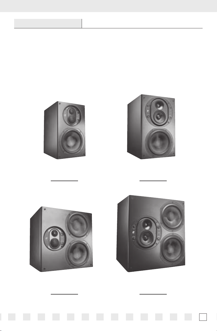
Pro1770LCR
Stock Number
FG01335
Pro2770LCR
Stock Number
FG01336
Pro1870LCR
Stock Number
FG01135
Pro2870LCR
Stock Number
FG01136
1
Page 4

FEATURES AND BENEFITS
INTERLACED CARBON-FIBER WOOFERS WITH BUTYL RUBBER SURROUNDS
Provide increased sound pressure levels and dynamic theater quality sound at
sustained high-power output
FLUID-COOLED TETERON™ DOME MIDRANGE*
*Pro1770LCR & Pro2770LCR models only
Produces smooth detailed dialog
FLUID-COOLED CARBON CONE MIDRANGE*
*Pro1870LCR & Pro2870LCR models only
Delivers sustained high output levels and smooth detailed dialog
FLUID-COOLED TETERON™ DOME TWEETERS
Deliver ultra-wide dispersion and silky-smooth response
ADJUSTABLE, CAST ALUMINUM, FULLY-ENCLOSED,
DISPERSION-CONTROLLING MIDRANGE/TWEETER POD
Enables precise imaging regardless of placement and accommodates vertical or
horizontal installations
BOUNDARY GAIN COMPENSATION CONTROL*
*Pro1870LCR & Pro2870LCR models only
Allows precise room matching
VARIABLE MIDRANGE AND TREBLE CONTROLS
Enables fi ne-tuning after installation (+/- 3dB)
CROSS-BRACED CABINETS
Provides the ultimate in rigidity and sound clarity
BI-AMP AND BI-WIRE CAPABILITIES
Optimizes tonal balance and enhances dynamic range
POLISHED BLACK CABINET WITH SCULPTED CHARCOAL ALUMINUM GRILLE
Provides an elegant yet unobtrusive appearance
DOLBY DIGITAL® READY
The StageFront Home Theater Solutions loudspeakers are expressly designed
for superior sonic quality in home theater applications. All models exceed the
specifi cations set forth by Dolby Laboratories for the accurate reproduction of Dolby
Digital-Encoded Sources
2
Page 5

INSTALLATION CONSIDERATIONS
RECOMMENDED AMPLIFIER POWER
For satisfactory performance, we recommend using a surround amplifi er with
a power rating of 20-150 watts for the Pro1770LCR and Pro2770LCR. We
recommend an amplifi er power rating of 20-200 watts for the Pro1870LCR and
Pro2870LCR. Most loudspeakers are not damaged by large amplifi ers, but rather
by small amplifi ers. If your system is playing at high levels, a small amplifi er will run
out of power very quickly and can create damaging “clipping” distortions. A more
powerful amplifi er will play at the same volume without distorting. See OPERATION
on page 9 for more information about amplifi er clipping distortion.
LOUDSPEAKER WIRE
Use 2-conductor loudspeaker wire when connecting loudspeakers to your receiver
or amplifi er. For most applications, we recommend using 16-gauge wire. For wiring
runs longer than 80 feet, we recommend 14-gauge wire. Every StageFront Pro
loudspeaker features gold-plated, fi ve-way binding posts that will accommodate up
to 12-gauge wire directly. Larger sizes can be accommodated via pin connectors.
NOTE: THESE FIVE-WAY BINDING POSTS CAN BE CONNECTED IN SEVERAL DIFFERENT WAYS (E.G.,
BANANA PLUGS, SPADE TERMINALS, AND DIRECT WIRING).
When running wire inside walls or ceilings, use special jacketed cable (CL-2 or CL-3)
to protect the wire and to meet local electrical and fi re codes. In some areas, conduit
is also required. For a trouble-free installation, low-voltage wire such as loudspeaker
wire must be run in accordance with the National Electrical Code and any applicable
provisions of the local building code. If you are unsure of the correct installation
techniques, wire jacket, or type of conduit to use, consult a professional audio/video
installer, building contractor, or the local building and inspection department.
TECH TIP
Wire size is expressed by its AWG (American
Wire Gauge) number – the lower the number,
the larger the wire. For example, 12 AWG is
physically larger than 14 AWG.
3
Page 6

LOUDSPEAKER PLACEMENT
NOTE: STAGEFRONT LCR LOUDSPEAKERS ARE DESIGNED FOR USE IN FRONT LEFT, CENTER OR
RIGHT-CHANNEL APPLICATIONS. FOR EFFECT CHANNEL APPLICATIONS, WE RECOMMEND USING A
STAGEFRONT FX LOUDSPEAKER.
PLACING THE STAGEFRONT LCR AS THE FRONT LEFT AND RIGHT
LOUDSPEAKERS
In a home theater, the intelligibility of dialog and action reproduced by the front
speakers is paramount! The position of each loudspeaker plays a very important
role in how clear the sound is and how a stereo image is created. Here are some
guidelines to make the process of placement quick and easy:
■ Make sure the sound will not be blocked or reflected off furniture or other objects.
The listener should have a direct line of sight with the front of the loudspeaker. To
determine the best position, measure the “listening” distance between the ideal
listening position (e.g., favorite chair or couch) and the wall in which you plan to
install the loudspeakers.
■ For stereo music applications, try to place the loudspeakers so that they are equally
distant from the listening spot and at least one half of the listening distance apart to
maintain a large pleasant stereo “image.”
■ In home theater applications where there is a center channel, you may choose to
space the left and right main loudspeakers farther apart for a “bigger than life”
sound with Dolby
and movie usage, we recommend using the placement zone for stereo music.
Ideally, if the listening position is 10 feet back from the wall, place the loudspeakers
between 5 and 10 feet apart, as shown in Figure 1.
®
encoded movies and TV shows. However, for combined music
Figure 1. Recommended
loudspeaker placement for
Loudspeaker
Placement Zone
10'
Loudspeaker
Placement Zone
4
5'
front left and right channels.
10'
Page 7

As for placement height, place front left and right loudspeakers on either side of the
picture source so that their tweeters are not more than 24 inches above or below
the center-channel loudspeaker’s tweeter (see Figure 2 on page 6).
NOTE: DO NOT PLACE ANY STAGEFRONT LCR OR FX LOUDSPEAKER TOO CLOSE TO A DIRECT-VIEW
TV MONITOR, AS IT MAY CAUSE PICTURE DISCOLORATION. IN GENERAL, TRY TO KEEP IT AT LEAST 24
INCHES AWAY FROM THE TV. WITH LARGER CRT SCREEN SIZES, TEST THE PLACEMENT DISTANCE FOR
PICTURE DEGRADATION BEFORE INSTALLATION.
THE BOUNDARY EFFECT
Placing a loudspeaker in a cabinet, as is likely for these models, or a corner
can powerfully affect the way a listener perceives bass response. Known as
the boundary effect, placing loudspeakers close to a wall/ceiling boundary, in a
cavity in a cabinet or near a corner wall boundary will emphasize certain bass
frequencies, while canceling others. This effect can make the loudspeaker sound
excessively boomy and inaccurate to some listeners, while to others it just seems
like more bass sound.
As a good rule-of-thumb, if you like listening to your current pair of loudspeakers
with the bass turned up, you’ll enjoy corner placement. However, if you listen
with the tone controls at neutral, try keeping the loudspeakers at least 2 or 3 feet
from the boundaries of the room. If this is not possible, the Pro1870LCR and
Pro2870LCR models feature a Boundary Compensation control to help correct any
issues that this type of placement can cause.
PLACING THE STAGEFRONT LCR AS THE CENTER-CHANNEL LOUDSPEAKER
The center-channel loudspeaker is the workhorse in a home theater system. It
handles all of the critical dialog and is vitally important in creating the illusion of
sounds emanating directly from the picture. Here are some tips for obtaining
optimum center-channel performance:
■ In a typical installation, place the loudspeaker horizontally, directly above or below
the television or projection screen. Try to ensure that the loudspeaker is not placed
too high relative to the left and right loudspeaker, as shown in Figure 2.
■ The Pro LCR models feature a Midrange/Tweeter pod that can be rotated to
accommodate horizontal installations. If you mount one of these models horizontally,
please remove the screws that hold this pod in place, rotate the pod ninety degrees
so that the tweeter is above the midrange and reinstall the screws to reattach the
pod to the loudspeaker as shown in Figure 3.
(CONTINUED ON NEXT PAGE)
5
Page 8

LOUDSPEAKER PLACEMENT (CONTINUED)
Pro1770LCR
(Optional Placement Above TV)
Pod rotated
(tweeter up)
Not Greater
than 24"
Pro1770LCRPro1770LCR
Pod rotated
(tweeter up)
Not Greater
than 24"
Pro1770LCR
Figure 2. Placing the Stagefront LCR as the center channel loudspeaker above or below a TV.
■ For installations where a perforated projection screen will be used, place the
loudspeaker, either horizontally or vertically, behind the screen at ear level, as
shown in Figure 3.
Pod rotated
Pro2870LCR
(horizontal position)
Pro2870LCR
(vertical position)
Figure 3. Recommended loudspeaker center-channel placement behind a perforated
projection screen.
6
Page 9

FINISHING THE INSTALLATION
CONNECTING THE LOUDSPEAKER
1. The terminals on your loudspeaker support Bi-amp or Bi-wire connections as well
as standard connections. Please choose your preferred method as described below
in Figure 5 on page 8.
2. At each loudspeaker, route the wire to the input
connectors, then separate the loudspeaker wire
so that at least 2 inches of each conductor are
free. Strip away 1/4 inch of insulation from each
loudspeaker wire. Using correct polarity, connect
the appropriate conductor to each five-way
binding post.
NOTE: OBSERVE CORRECT POLARITY: POSITIVE
(+) GOES TO THE RED POST AND NEGATIVE (–)
GOES TO THE BLACK POST. IF YOU ARE UNSURE OF
WIRE POLARITY, SEE THE SECTION, CHECKING
LOUDSPEAKER PHASE BELOW.
3. Connect the other end of the loudspeaker wires to the home theater receiver (or
amplifier) in the same way.
4. Turn on the home theater receiver and calibrate all loudspeakers in the system
according to the receiver manufacturer’s instructions.
Figure 4. Connecting loudspeaker
wires to the terminals.
BI-WIRE AND BI-AMP CHOICES
Bi-Wiring
In a Bi-Wired confi guration, separate cables are connected from the amplifi er or
receiver output terminals to the speaker input terminals for the tweeter/midrange
section and the woofers. Be sure to remove the straps linking the two sets of
input terminals on the speaker. Your amplifi er and your loudspeakers may be
damaged if you do not remove the straps. This type of confi guration results in
lower resistance between the amplifi er and speaker than a standard connection
with the same gauge cable. Some listeners may prefer Bi-Wiring to a standard
connection with lower gauge cable.
Bi-Amping
In a Bi-Amplifi ed system, the tweeter and midrange section are driven by a
separate amplifi er than the woofer. Both amplifi ers are connected to the same
preamplifi er output. Use the same model amplifi er for the tweeter and woofer
inputs and be sure to remove the straps linking the two sets of input terminals
on the speaker. Your amplifi ers and your loudspeakers may be damaged if you do
not remove the straps.
(CONTINUED ON NEXT PAGE)
7
Page 10

FINISHING THE INSTALLATION (CONTINUED)
Figure 5. Bi-Wire connection
Figure 6. Bi-Amp connection
Si275 Amp
Straps Removed
Pro2870 LCRPro2870 LCR
Surround Receiver
Si275 Amp1
Si275 Amp2
Straps Removed
Pro2870 LCRPro2870 LCR
CHECKING LOUDSPEAKER PHASE
Speaker wire has two conductors. On both your loudspeaker and amplifi er, one
conductor is attached to the negative (–) terminals, while the other is attached to
the positive (+) terminals. Usually, the wire is marked for your convenience, but the
marking can be done in the following different ways:
■ Stripe on one wire
■ Ribbed area you can feel on one conductor
■ Different colors of metal wire on each conductor
■ Fabric strand or string wound into one of the conductors
Of course, there are some wires that appear completely identical. So be careful, or
you might make a connection mistake. If you do, one loudspeaker will be playing
“out-of-phase” with the other loudspeaker. A pair of out-of-phase loudspeakers
8
Page 11

works against each other, and the sound of the two playing together will be lacking
in bass and sound “phasey.” If you suspect the sound is not right, and you cannot
see any markings on the wire, try this simple test:
1. Stand halfway between the loudspeakers.
2. Play some music with the amplifier or radio set to Mono.
3. Listen to the richness of the bass and the loudness of the sound.
4. Turn off the amplifier and reverse the connections on one amplifier channel only.
5. Repeat the listening test with the same volume control setting. When the sound has a
richer bass and is slightly louder, the loudspeakers are working together or “in-phase.”
ACOUSTIC FINE TUNING
Each StageFront Pro LCR loudspeaker features a variable Treble and Bass Controls.
The 1870LCR and 2870LCR models also feature Boundary Gain Compensation and
Pod Level controls located on the front for acoustic fi ne-tuning after placement, as
shown in Figure 7. Adjust these controls as follows:
■ Ensure that the Treble and Midrange controls are set to Flat (0 dB).
■ If a Stagefront Pro LCR is placed in a room with highly reflective surfaces like glass or
tile or the reproduced sound is too bright, set the Treble control to – 3 dB to lower the
high frequency response.
■ Listen to dialog being reproduced on the Stagefront Pro LCR. If you want it more
pronounced, set the Midrange control to up to +3dB to enhance the mid-frequency
response.
Figure 7. Treble and Midrange
controls for the Pro1770LCR and
Figure 8. Treble, Midrange, Pod Level and Boundary
Compensation controls for Pro1870LCR and Pro2870LCR.
Pro2770LCR
(CONTINUED ON NEXT PAGE)
LCR
9
Page 12

FINISHING THE INSTALLATION (CONTINUED)
The StageFront Pro1870LCR and Pro2870LCR models feature Boundary
Compensation and Pod Level controls in addition to those for Treble and Midrange
levels. These controls are also on the front for acoustic fi ne-tuning after placement,
as shown in Figure 8. Adjust these controls as follows:
■ If a Pro LCR is placed in a cabinet or position where the loudspeaker is closer than
2 to 3 feet from a room boundary, such as a wall, and the sound is ‘boomy’, please
switch the Boundary Compensation switch on. You may need to also adjust the
Midrange level when using this switch.
■ The Pod Level control allows you to adjust the level of the Tweeter and Midrange in
relation to the woofer(s) of the loudspeaker. If you are getting ‘boomy’ response after
adjusting the Midrange level and the Boundary Compensation switch, you may need
to increase the level of the Pod in relation to the woofer(s). If you are getting thin or
‘tinny’ response after adjusting the Tweeter level and the Boundary Compensation
switch, you may need to decrease the pod level in relation to the woofer(s).
■ Please remember to also check the settings of your receiver or processor if you
cannot achieve satisfactory sound once you have tried adjusting the controls of
the loudspeaker.
INSTALLING THE GRILLE
If desired, at each loudspeaker, carefully fi t the grille to its cabinet. Starting with one
corner, gently press the grille frame around the loudspeaker’s edge, pushing it in at
each of the four recessed holes. When properly installed, the edges of the grille will
be nearly fl ush in appearance with the cabinet.
OPERATION
LISTENING AT HIGHER VOLUMES
Achieving a reasonable volume of sound in a large room requires more amplifi er
power than it does in a small room. It is possible to turn the volume up so high
that the amplifi er runs out of power. This creates “clipping” distortion, which will
make treble sound very harsh and unmusical. When you hear harsh-sounding
treble from any good loudspeaker, turn the volume down immediately! Those
harsh sounds are masking much more powerful ultra-high-frequency sound
spikes, which will quickly damage any fi ne loudspeaker. You are much less likely
to damage a loudspeaker driven by a large amplifi er because it will be very loud
before any clipping distortion is produced.
CLEANING
Clean the StageFront Home Theater Solutions loudspeaker with a dampened soft
cloth or paper towel.
10
Page 13

SPECIFICATIONS
Pro1770LCR
Recommended Amplifi er Power
20-150 watts per channel
Nominal Impedance
6 ohm nominal; 3.2 ohm minimum
Frequency Response
70Hz to 20kHz, +/- 3 dB
Sensitivity
88 dB with 2.83 V pink noise input measured at
1 meter on axis
Dimensions
8-7/8” W x 14-5/8” H x 12-5/8” D with grille
Depth is 12-3/8” without grille
Wiring Requirements
We recommend using 16-gauge loudspeaker
wire for runs up to 80 feet and 14-gauge
speaker wire for runs up to 200 feet. The
connectors will accommodate 12 to 22
gauge wire.
Pro2770LCR
Recommended Amplifi er Power
20-150 watts per channel
Nominal Impedance
6 ohm nominal; 3.2 ohm minimum
Frequency Response
60Hz to 20kHz, +/- 3 dB
Sensitivity
89 dB with 2.83 V pink noise input measured at
1 meter on axis
Dimensions
14-5/8” W x 14-5/8” H x 12-5/8” D with grille
Depth is 12-3/8” without grille
Wiring Requirements
We recommend using 16-gauge loudspeaker
wire for runs up to 80 feet and 14-gauge
speaker wire for runs up to 200 feet. The
connectors will accommodate 12 to 22
gauge wire.
Pro1870LCR
Recommended Amplifi er Power
20-200 watts per channel
Nominal Impedance
6 ohm nominal; 3.2 ohm minimum
Frequency Response
60Hz to 20kHz, +/- 3 dB
Sensitivity
90 dB with 2.83 V pink noise input measured at
1 meter on axis
Dimensions
11” W x 17-1/2” H x 15-3/8” D with grille
Depth is 15-1/4” without grille
Wiring Requirements
We recommend using 16-gauge loudspeaker
wire for runs up to 80 feet and 14-gauge
speaker wire for runs up to 200 feet. The
connectors will accommodate 12 to 22
gauge wire.
Pro2870LCR
Recommended Amplifi er Power
20-200 watts per channel
Nominal Impedance
6 ohm nominal; 3.2 ohm minimum
Frequency Response
55Hz to 20kHz, +/- 3 dB
Sensitivity
91 dB with 2.83 V pink noise input measured at
1 meter on axis
Dimensions
17-1/2” W x 19-1/8” H x 15-3/8” D with grille
Depth is 15-1/4” without grille
Wiring Requirements
We recommend using 16-gauge loudspeaker
wire for runs up to 80 feet and 14-gauge
speaker wire for runs up to 200 feet. The
connectors will accommodate 12 to 22
gauge wire.
11
Page 14

LIMITED WARRANTY
N ILES AUDIO COR PORATIO N (“NILE S”) WARR ANTS IT S PASSIVE LOUDS PEAK ER PRODUC TS (THO SE NOT REQUI RING
AC OR BATTERY POWER) TO THE ORIGINAL PURCHASER TO BE FREE OF MANUFACTURING DEFECTS IN MATERIAL
AND WORKM ANSHIP FOR A PERIOD OF FIVE YEARS FROM DATE OF PURCHASE.
THIS WARRANTY IS SUBJECT TO THE FOLLOWING ADDITIONAL CONDITIONS AND LIMITATIONS. THE WARRANTY
IS VOID AND IN APPLICABLE IF NILES DEEMS THAT THE PRODUCT H AS BEEN USED OR HANDLED OTHER TH AN IN
ACCORDANCE WITH THE INSTRUCTIONS PROVIDED BY THE MANUFACTURER, INCLUDING BUT NOT LIMITED TO
DAMAGE CAUSED BY ACCIDENT, MISHANDLING, IMPROPER INSTALLATION, ABUSE, NEGLIGENCE, OR NORMAL
WEAR AND TEAR, OR ANY DEFECT CAUSED BY REPAIR TO THE PRODUCT BY ANYONE OTHER THAN NILES OR AN
AUTHORIZED NILES DEALER.
TO OBTAIN WARRANTY SERVICE, TAKE THE UNIT TO THE NEAREST AUTHORIZED NILES DEALER, WHO WILL TEST
THE PRODUCT AND IF NECESSARY, FORWARD IT TO NILES FOR SERVICE. IF THERE ARE NO AUTHORIZED NILES
DEALERS IN YOUR AREA, YOU MUST WRITE TO NILES AND INCLUDE YOUR NAME, MODEL AND SERIAL NUMBER OF
YOUR UNIT, ALONG WITH A BRIEF DESCRIPTION OF THE PROBLEM. A FACTORY RE TURN AUTHORIZATION NUMBER
WILL BE SENT TO YOU. DO NOT RETURN ANY UNIT WITHOUT FIRST RECEIVING WRITTEN AUTHORIZATION AND
SHIPPING INSTRUCTIONS FROM NILES.
IF THE ABOVE CONDITIONS ARE MET, THE PURCHASER’S SOLE REMEDY SHALL BE TO RETURN THE PRODUCT TO
NILES, IN WHICH CASE NILES WILL REPAIR OR REPLACE, AT ITS SOLE OPTION, THE DEFECTIVE PRODUCT WITHOUT
CHARGE FOR PARTS OR L ABOR. NILES WILL RETURN A UNIT REPAIRED OR REPLACED UNDER WARRANT Y BY
SH IP PI NG S AM E BY IT S US UA L SH IP PI NG M ET HOD F RO M TH E FA CT ORY ( ON LY) AT I TS E XP EN SE WI TH IN THE U NI TED
STATES OF AMERICA. THERE ARE NO OTHER WARRANTIES, INCLUDING WITHOUT LIMITATION, EITHER EXPRESS
OR IMPLIED WARRANTIES OF MERCHANTABILITY OR FITNESS FOR A PARTICULAR PURPOSE, WITH RESPECT TO
THE PRODUCT.
REPAIR OR REPLACEMENT AS PROVIDED UNDER THIS WARRANTY IS THE EXCLUSIVE REMEDY OF THE CONSUMER/
PURCHASER. NILES SHALL NOT BE RESPONSIBLE FOR ANY INCIDENTAL OR CONSEQUENTIAL DAMAGES EXCEPT
TO THE EXTENT PROVIDED (OR PROHIBITED) BY APPLICABLE LAW.
SOME STATE S DO NO T A LLOW TH E EXC LUSION OR LIM ITATION OF INC ID ENTA L OR CON SEQU ENTIAL DA MAG ES, S O
THE ABOVE LIMITATION MAY NOT APPLY TO YOU. THIS WARRA NT Y GIVES YOU SPECIFIC LEGAL RIGHTS, AND YOU
MAY ALSO HAVE OTHER RIGHTS WHICH VARY FROM STATE TO STATE.
FOR THE NAME OF YOUR NEAREST AUTHORIZED NILES DEALER CONTACT:
NILES AUDIO CORPORATION, P.O. BOX 160818, MIAMI, FLORIDA 33116-0818.
Please fill in your product information and retain for your records.
Model_____________________ Serial No._________________ Purchase Date________
12
Page 15

WARRANTY REGISTRATION CARD
Model Purchased _________________________________________________________
Serial Number ___________________________________________________________
Date Purchased (month/day/year) _____________________________________________
Dealer Name and Location __________________________________________________
______________________________________________________________________
❍
Dr.
❍
Miss
❍
Mr.
❍
Mrs.
❍
Ms.
Name__________________________________________________________________
Address________________________________________________________________
______________________________________________________________________
City_______________________________________State________________Zip ______
Telephone ( )_______________________email _______________________________
Please take a moment to fi ll out our warranty registration card. The information helps us to get to
know you better and develop the products you want
Age:
❍
Under 25
❍
25-34
❍
35-44
❍
45-54
❍
55 & over
Income:
❍
Under $44,999
❍
$45,000-$59,999
❍
$60,000-$74,999
❍
$75,000-$99,999
❍
$99,999-$150,000
❍
$150,000-$99,999
❍
$99,999-$200,000
❍
Over $200,000
Occupation:
❍
Arts/Entertainment
❍
Business Owner
❍
Engineer
❍
Finance/Accounting
❍
General Office
❍
Management
❍
DETACH HERE AND RETURN TO: NILES AUDIO CORPORATION WARRANTY REGISTRATION DEPT. P.O. BOX 160818 MIAMI, FLORIDA 33116-0818
Professional
❍
Sales/Marketing
❍
Student
❍
Tradesperson
Musical tastes:
(Please check
all that apply)
❍
Alternative
❍
Classical
❍
Country
❍
Jazz
❍
New Age
❍
Popular
❍
R&B
❍
Rock
❍
Other _____________
How did you hear
about Niles?
❍
Architect/Developer
❍
Custom Installer
❍
Direct Mail
❍
Friend/Family
❍
In-Store Display
❍
Interior Designer
❍
Magazine Ad
❍
Mail-Order Catalog
❍
Newspaper Ad
❍
Product Brochure
❍
Product Review
❍
Retail Salesperson
❍
Internets
❍
Other
What magazines
do you read?
1. ________________
2. ________________
3. ________________
Who will install
the product?
❍
Custom Installer
❍
Electrician
❍
Friend
❍
Myself
Which factor(s) influenced
the purchase of your Niles
product? (Please check
all that apply)
❍
Ease of Use
❍
Price/Value
❍
Product Features
❍
Quality/Durability
❍
Reputation
❍
Style/Appearance
❍
Warranty
Do you . . . ?
❍
Own a House. If yes,
how many square feet?
❍
Own a Town House/
Condominium/Co-op
❍
Rent an Apartment
❍
Rent a House
Are you interested in
receiving literature on
other Niles products?
❍
Yes
Are there products/
capabilities that you would
like to see introduced?
❍
No
13
Page 16

NILES AUDIO CORPORATION
12331 SW 130 Street, Miami, FL 33186 1-800-BUY-HIFI – www.nilesaudio.com
©2006 Niles Audio Corporation. All Rights Reserved. Niles and the Niles logo are registered trademarks of
Niles Audio Corporation. Stagefront Home Theater Solutions is a trademark of Niles Audio Corporation.
All other trademarks are the property of their respective owners. DS00508A
 Loading...