

Page 1
INSTALLATION & OPERATION GUIDE
PAR4
PAR4
SIMPLIFIED INFRARED ROUTER
B LENDING H IGH F IDELITY AND A RCHITECTURE
®
Page 2

PAR4
Simplified Infrared
Router
S
IMPLIFIEDINFRARED
R
OUTER
TABLE OF CONTENTS
Introduction 1
Features and
Benefits 2
PAR4 Parts
Guide 4
Installation
Considerations 5
Operation 7
Specifications 9
Introduction
An infrared router enables you to control identical audio/video
components independently of each other. This allows you to
incorporate multiple CD changers, DSS receivers, televisions,
etc. of the same make and model into a home entertainment
system and control them individually.
Installed in the equipment location, the PAR4 is connected to
your infrared (IR) extender system and turns pre-specified
“routes” on and off, passing infrared commands to a single
component or group of components.
The PAR4 is compatible with all current Niles infrared Main
System Units (MSUs). It may be used along with the MSU140,
MSU250, MSU480 and the MSU440Z.
Page 3

S
IMPLIFIED
I
NFRARED
R
OUTER
Features and Benefits
The PAR4 offers a number of improvements over other IR routers:
• Universal system – compatible with virtually all brands of A/V
equipment and remote controls
• Routes IR commands to four components
• Simple plug and play operation
• No programming – simply select the route needed from an exist-
ing list of IR commands
• Expandable – cascade two units together to create eight routes
• Printed circuit board design assures high reliability
• Low profile and small footprint with integrated mounting wings
that allow for both horizontal and vertical installation
• UL listed regulated in-line power supply with universal voltage
capability
• Two year parts and labor warranty
2
Page 4
S
IMPLIFIED
I
NFRARED
R
OUTER
Niles IR
Flasher
12VDC power
supply (supplied)
plugged into an
witched AC
uns
wers
outlet po
the system
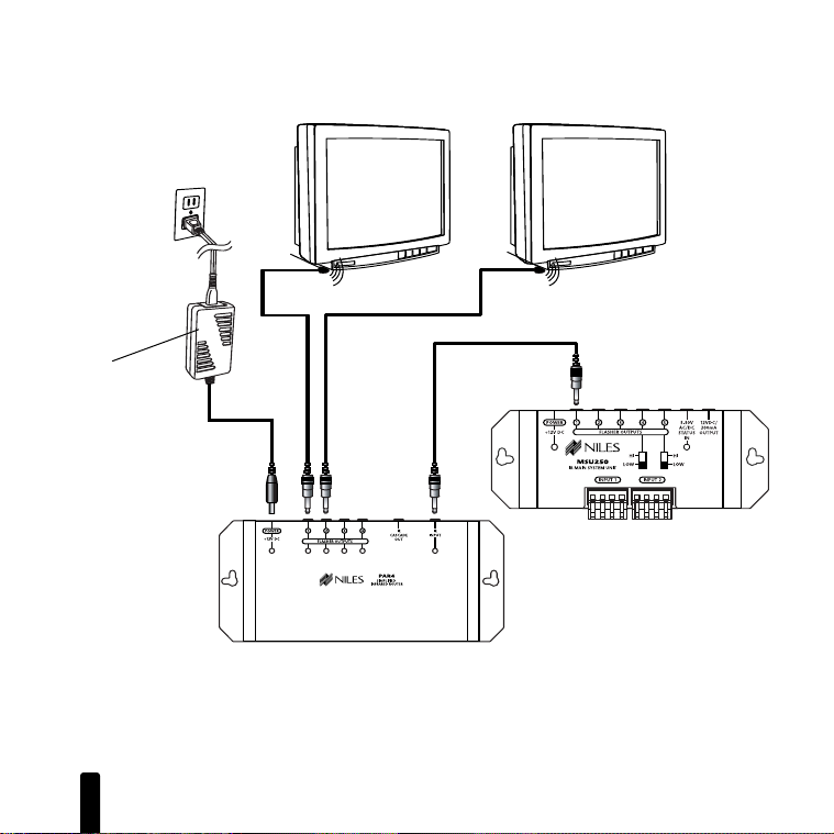
Figure 1
Diagram of PAR4 connecting to the flasher
output of a MSU250 with flasher outputs
controlling devices.
3
Niles IR
Flasher
PAR4
MSU250
Page 5

S
IMPLIFIED
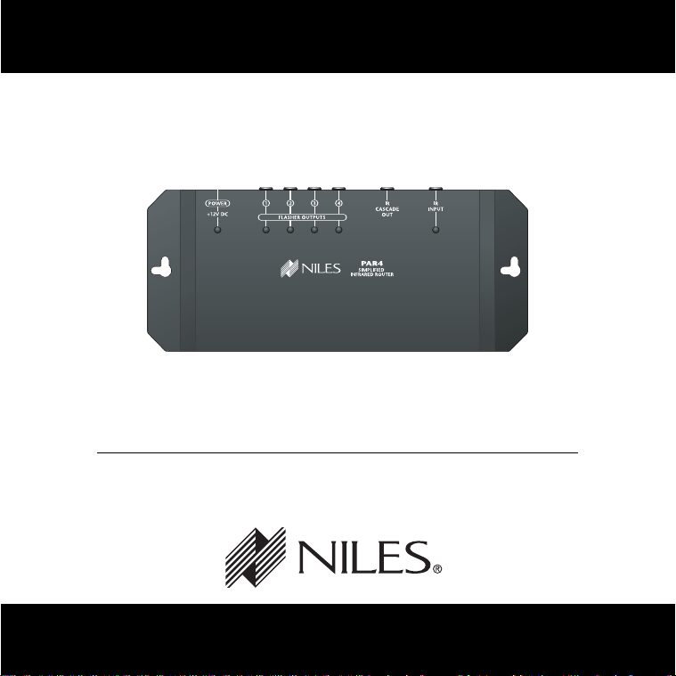
PAR4 Parts Guide
1
I
NFRARED
2
R
OUTER
3
4
1. 12V DC Jack – Provides 12 volt DC power to
PAR4 via a regulated power supply
2. IR Route (Flasher) Outputs – 3.5mm jacks
provide output for single low-level flashers
3. Cascade Output – 3.5mm jack provides for
connection of second PAR4
4. IR Input – 3.5mm jack provides for connection
from the IR flasher output of a Niles Main
System Unit
4
Page 6

S
1
2
3
4
POWER
+1
2V DC
FLASHER OU
TPUTS
MSU
1
4
IR MAIN
SYSTE
INPUT
1
IMPLIFIED
Installation Considerations
Placement of the PAR4
Place the PAR4 conveniently close to the main system unit it
will connect to. Generally, the PAR4 is placed in a concealed
location because its indicator lights are only used during installation. Placement possibilities include:
1. Table-top (on the floor or shelf behind the equipment)
2. Wall-mount (affixed to the back of the equipment cabinet
I
NFRARED
(Figure 2).
or a nearby wall) (Figure 3).
PAR4 Base
Self-Adhesive
Rubber Feet
R
OUTER
Figure 2: Table-top placement
Affix the enclosed self-adhesive
rubber feet to the base of the PAR4.
5
Figure 3: Wall-mount placement
Use sheetrock screws.
Page 7

S
IMPLIFIED
I
NFRARED
R
OUTER
Installation Considerations (continued)
Before you begin, make sure that the flasher cables and the 12VDC power supply cable will
all reach the proposed location of the PAR4. Mark the cables with labels describing where
the cable originates (i.e. TV1) rather than which terminal on the PAR4 it should connect.
STEP DESCRIPTION
1. Connect and test the
power supply.
2. Plug the flashers (not supplied) into the flasher outputs.
e 4.
See figur
3. Connect the PAR4 to the
IR main system unit using
a 3.5mm mono cable of
appropriate length.
See figure 1.
A) Plug the supplied 12VDC power supply into an unswitched
100-240V AC outlet.
B) Plug the connector into the socket labeled “power” on the
PAR4.
C) If the power LED on the PAR4 does not light, test the
unswitched AC outlet with another appliance. If the outlet tests
OK, you have a defective power supply which must be replaced
before you continue. If the red power LED illuminates unplug
the connector from the power socket and proceed.
A) Recommended flashers are Niles MF1 or MF1VF MicroFlashers.
If you need to extend the wire, use 2 conductor, 16 gauge
stranded wir
B) When extending the flasher wire be sure to observe proper polarity.
C) The wire marked with the grey stripe is positive (+); the unmarked
lead is negative (-).
A) Plug one end of the cable into the IR output of the main system
unit (a flasher output on any Niles MSU).
B) The other end of the cable is plugged into the jack labeled “IR
Input” on the PAR4.
C) During normal operation the blue IR indication LED will flicker
when the PAR4 is receiving IR data from the output device.
e.
6
Page 8

S
IMPLIFIED
I
NFRARED
R
OUTER
IMPORTANT
MMaakkee aallll ffiinnaall
ccoonnnneeccttiioonnss ttoo tthhe
rroouutteerr bbeeffoorree
ccoonnnneeccttiinngg tthhe
ppoowweerr ssuuppppllyy..
TThhiiss wwiillll aavvooiid
ppootteennttiiaall ddaammaagge
ttoo ccoommppoonneennttss.
7
d
BE SURE TO OBSERVE PROPER
POLARITY WHEN EXTENDING
e
e
e
Figure 4
.
THE FLASHER WIRE.
The wire lead marked with a
gray stripe is positive (+); the
unmarked lead is negative (-).
Operation
Operating the PAR4 is a simple matter of selecting the appropriate IR codes you need from a table of supplied code sets.
See figure 5. The IR codes are available for download from the
Niles Technical Support website:
http://www.nilesaudio.com/techsupport
1. On the Niles Technical Support website select the brand
of remote control you will use to control the PAR4 (i.e.
the Niles IntelliControl) and download the file for that
remote control. After downloading the file you will need to
import it into the programming software for the selected
remote control.
2. From the supplied table select the route you wish to
use (i.e. code 1: all four routes on) and load it into the
remote control.
3. Test the code by operating the remote and observing the
flasher LEDs on the PAR4. For example, if the “all on” command is issued, all four LEDs should illuminate indicating
that all four routes are active.
Page 9

S
IMPLIFIED
I
NFRARED
R
OUTER
CODE FLASHER 1 FLASHER 2 FLASHER 3 FLASHER 4
01 ON ON ON ON
02 OFF OFF OFF OFF
03 ON OFF OFF OFF
04 OFF ON OFF OFF
05 OFF OFF ON OFF
06 OFF OFF OFF ON
07 ON ON OFF OFF
08 ON ON ON OFF
09 OFF ON ON ON
10 ON ON OFF ON
11 ON OFF ON ON
12 ON OFF OFF ON
13 ON OFF ON OFF
14 OFF ON ON OFF
15 OFF ON OFF ON
16 OFF OFF ON ON
Figure 5: Table of IR Code Sets
8
Page 10

S
IMPLIFIED
Using Two PAR4 Routers
You may daisy chain two PAR4 IR routers together to provide
routing for up to eight identical devices. This is accomplished
by connecting two PAR4 routers together using a mono
3.5mm cable (not supplied). See figure 6. On PAR4 “B” the
3.5mm cable is plugged into the “IR cascade out” jack. On
PAR4 “A” the 3.5mm cable is plugged into the jack labeled “IR
input”.
Operation for two units is similar to operating a single PAR4
with the exception that a separate table of IR routing codes
(table A and table B) exists for PAR4
Note: When two PAR4 IR Routers are daisy chained
together codes from table A will not operate PAR4
unit B and vice versa.
Specifications
Unit Dimensions
7-1/16” wide x 1-1/4” high x 3” deep
I
NFRARED
R
OUTER
(A) and PAR4 (B).
Power Requir
12VDC 1.25A regulated power supply (included).
9
ements
Page 11

S
IMPLIFIED
I
NFRARED
R
OUTER
Figure 6
PAR4 (A)
IR Input
Flasher
Output
MSU250
PAR4
IR Cascade
Out
(B)
10
Page 12

Niles Audio
Corpora
tion
www.nilesaudio.com
12331 S.W. 130 Street
Miami, Florida, 33186
Tel: (305) 238-4373
Fax: (305) 238-0185
2005 Niles Audio Corporation. All rights reserved. Niles, the Niles logo, IntelliPad and Blending High Fidelity
©
and Architecture are registered trademarks of Niles Audio Corporation. MicroFlasher is a trademark of Niles
Audio Corporation. Because we strive to improve our products. All other trademarks are the property of their
respective owners. Niles reserves the right to change product specifications without notice. The technical and
other information contained herein is not intended to set forth all technical and other specifications of
Niles products. Additional information can be obtained on-line at www.nilesaudio.com or by calling Niles at
1-800-289-4434. Printed in China. 01/05 DS00429ACN
 Loading...