

Page 1
INSTALLATION & OPERATION GUIDE
One Input, Six Individually Adjusted Room Outputs,
Keypad or IR Control With One Touch Automation
MRZ-6
MRZ-6
Line Level Multi-Room Controller
B LENDING H IGH F IDELITY AND A RCHITECTURE
™
Page 2

Congratula tions!
Thank you for purchasing the Niles MRZ-6 Multi-Room Control System, one of the most flexible and convenient audio
components ever offered. The MRZ-6, like all Niles products, is built to the highest standards of quality and reliability.
With proper installation and operation, you'll enjoy years of trouble-free use.
Niles manufactures the industry's most complete line of custom installation components and accessories for audio/video
systems. For a free full line catalog write:
Niles, Catalog Request, P.O. Box 160818, Miami, Florida 33116-0818
Table Of Contents
INTRODUCTION . . . . . . . . . . . . . . . . . . . . . . . . . . . . . . . . . . . . . . . . . . . . . . . . . . . . . . . . . . . . . . . . . . . . . . . . . .1
FEATURES AND BENEFITS . . . . . . . . . . . . . . . . . . . . . . . . . . . . . . . . . . . . . . . . . . . . . . . . . . . . . . . . . . . . . . . . . . .2
PARTS GUIDE . . . . . . . . . . . . . . . . . . . . . . . . . . . . . . . . . . . . . . . . . . . . . . . . . . . . . . . . . . . . . . . . . . . . . . . . . . . .4
USING THE STRAIN RELIEF BAR . . . . . . . . . . . . . . . . . . . . . . . . . . . . . . . . . . . . . . . . . . . . . . . . . . . . . . . . . . . . . .5
AUDIO CONNECTIONS . . . . . . . . . . . . . . . . . . . . . . . . . . . . . . . . . . . . . . . . . . . . . . . . . . . . . . . . . . . . . . . . . . . .6
INFRARED CONTROL CONNECTIONS . . . . . . . . . . . . . . . . . . . . . . . . . . . . . . . . . . . . . . . . . . . . . . . . . . . . . . . . .9
DISTRIBUTING IR COMMANDS . . . . . . . . . . . . . . . . . . . . . . . . . . . . . . . . . . . . . . . . . . . . . . . . . . . . . . . . . . . . .10
WIRING DIAGRAMS FOR INFRARED CONTROL . . . . . . . . . . . . . . . . . . . . . . . . . . . . . . . . . . . . . . . . . . . . . . . .11
SETTING THE DIP SWITCHES . . . . . . . . . . . . . . . . . . . . . . . . . . . . . . . . . . . . . . . . . . . . . . . . . . . . . . . . . . . . . . . .19
FINAL CONNECTIONS . . . . . . . . . . . . . . . . . . . . . . . . . . . . . . . . . . . . . . . . . . . . . . . . . . . . . . . . . . . . . . . . . . . .20
PROGRAMMING AND AUTOMATING YOUR SYSTEM . . . . . . . . . . . . . . . . . . . . . . . . . . . . . . . . . . . . . . . . . . . .26
APPENDIX - HOW TO PROGRAM WHEN YOU HAVE LOST THE TEMPLATE . . . . . . . . . . . . . . . . . . . . . . . . . . .27
SPECIFICATIONS . . . . . . . . . . . . . . . . . . . . . . . . . . . . . . . . . . . . . . . . . . . . . . . . . . . . . . . . . . . . . . . . . . . . . . . . .28
Page 3
Introduction
The MRZ-6 Line Level Multi-Room Controller combines with the Niles SI-1230 twelve channel power amplifier to enable
you to individually adjust the room volume of up to six rooms. One source is fed to all of the rooms from the record output, preamp output or second zone output of any preamp/receiver. Six MRZ-6 systems can be interconnected in single
or multiple zone configurations (up to 36 rooms). Each group of six rooms (one MRZ-6) can be powered by a single Niles
SI-1230 twelve channel power amplifier or by any mix of conventional power amplifiers.
By using optional Niles remote controls, keypads or the front panel of the MRZ-6, you may control room volume, local
room on/off and global system commands (CD All On, Tuner All On and All Off). On the unique Niles RP-9 keypad
two buttons (labeled CD and Tuner) offer one touch intelligent operation; a single touch turns on the preamp/receiver,
selects the correct input and issues one additional IR command (to play the CD or select your favorite radio station). IR
sensors (using hand-held learning remote controls) or Niles IntelliPads are also capable of one touch automation and
can offer full control of up to six sources.
1
ON/OFF VOLUME ALLON AL LOFF
MRZ-6
MULTI-ROOM ZONE CONTROLLER
123456
INFRARED ROOM CONTROL
TEACH CONFIRM
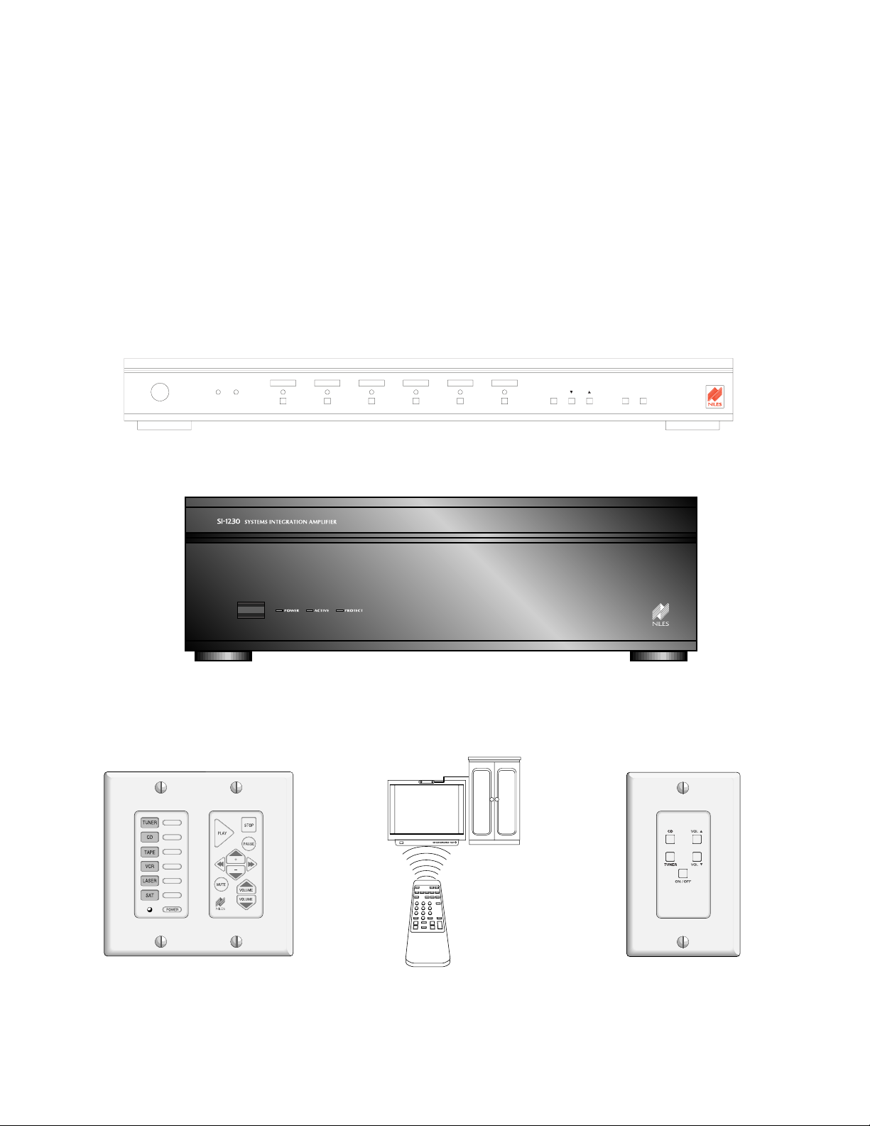
Figure 1 The MRZ-6 Multi-Room Controller.
Figure 2 The SI-1230 twelve channel configurable power amplifier.
Figure 3 Hand-held remote control via
IR sensors
Figure 2 One touch automation and
full source control for up to six
sources via IntelliPads
♦
Figure 4 One touch
automation for CD and
tuner via RP-9 keypads
Choose the type of control you need. Freely integrate any combination of keypads and sensors in each room and throughout the system.
Page 4

Features and Benefits
Audiophile Quality Independent Line-Level Volume Control
The ultimate in sound quality for every room in the house. Each room is independently adjusted for volume
via one of the six built-in volume controls. Unique digital line-level gain circuits provide 136dB of dynamic
range in 1dB increments with distortion and noise specifications that are unbelievably low when compared to
conventional circuitry. The MRZ-6 multi-room system makes no compromises in audio performance.
Never Disturb Others
The MRZ-6 ROOM ON/OFF and VOLUME UP/DOWN commands enable you to control the room you are
in without affecting the rest of the system. You can fine tune your listening area without disturbing others in
another room. Of course, if you turn on the system, only the room you are in turns on. The rest of the house
stays muted until music is desired in another room.
A Single Touch Turns On All of Your Favorite Rooms
All of your favorite rooms can be turned on instantaneously by pressing and holding either the CD or the Tuner
buttons for more than two seconds. Switches on the rear panel of the MRZ-6 enable you to individually choose
which rooms turn on when the ALL ON command is received (so that the baby’s room does not turn on when
you are entertaining).
A Single Touch Turns Off Your Entire System
Pressing and holding the On/Off button on a keypad or a remote control will turn off
all
rooms and turn off
your preamp/receiver, CD player and other components. You will never worry if something is still on when
you go to bed or leave the house.
One Touch Automation For CD and Tuner With the Niles RP-9 Keypad
The RP-9 keypads have two keys labeled “CD” and “T uner”. When the CD button is pressed, the MRZ-6 intelligently “checks” to see if your preamp/receiver and CD player are on or off. If they are off, the MRZ-6 turns
them on. Then after it “knows” that the components are on, it selects the CD as the source and issues the “Play”
command (a two step macro). Likewise, when you press the Tuner button, the system is configured for you
to listen to radio (another two step macro).
This is accomplished by teaching the MRZ-6 the “power” command (or separate “on” and “off” commands),
the “CD” and “Tuner” input commands for the preamp/receiver; one additional command for the CD player
(typically “play” or “random-play”) and one additional command for the Tuner (some tuners respond to a single numeric command by recalling a favorite radio station).
One Touch Automation and Full Source Control for up to Six Components with the Niles IntelliPad
The Niles IntelliPad provides intelligent turn on and ten step macros for up to six sources. The sour ces are custom labeled on six backlit keys. Additionally, after a source has been selected, the right hand buttons of the
IntelliPad offer full control of the selected source (i.e. play, stop, pause, disc skip up, disc skip down, track skip
up and track skip down) and volume up, down and mute.
One Touch Automation and Full Source Control via Niles IR sensors
All IR commands required to control the MRZ-6 can be taught to a learning remote control via the the MRZ-6’s
teaching IR flasher . This conveniently integrates control of your source components with control of your MRZ-6.
Niles IR sensors relay commands and sequences from the learning remote control to the MRZ-6 and display the
status of a room (a green LED lights when the room is on). Niles manufactures a wide range of IR sensors, including in-wall, cabinet-mount, surface-mount, tabletop or even omnidirectional ceiling-mount sensors.
2
Page 5

Strain Relief Bar For All Connected Cables
A supplied steel bar attaches to the rear of the MRZ-6. By looping any cable around the strain relief bar before
you connect it to the MRZ-6, you relieve all strain on the cables. Now, anytime you move the MRZ, you move
the cables too, no more accidental disconnects.
Total Front-Panel Control
The front panel buttons of the MRZ-6 enable you to control ALL ON, ALL OFF, ROOM ON/OFF and VOLUME UP/DOWN. When entertaining family and friends, whole-house volume changes are easy and convenient.
Single, Dual and Multi-Zone Capable
Multiple MRZ-6s can be configured into systems where all rooms listen to the same source or as multiple listen ing zone systems, where each MRZ-6 (up to 6 rooms) is connected to a dedicated source selecting preamp/receiver creating a system where more than one source can be enjoyed simultaneously within the house.
Configurable Power With The Niles SI-1230
The Niles SI-1230 twelve channel amplifier enables you to configure the power for each area, selecting 15
watts per speaker (two speakers in mono fed from one channel), 30 watts per speaker (two speakers in stereo
each fed from a dedicated channel) or 80 watts per speaker (two speakers in stereo each fed from a pair of
bridged channels).
Compatible With Any Power Amplifier
The MRZ-6 is compatible with any power amplifier. As a result you may configure the power as your needs
dictate; a large amplifier for outdoor or critical listening areas and smaller amplifiers for small rooms or background areas.
Easy System Expansion
Up to six MRZ-6’s can be linked to control systems with up to 36 rooms. When linked, Global ALL ON or ALL
OFF commands affect the entire system. In addition, connected infrared controlled source equipment may be
controlled from any room with an IR sensor or IntelliPad.
Control Output
The 12V DC CONTROLOUT and an optional Niles AC-3 voltage-activated AC power switching system (Niles
stock# FG00242) enable your MRZ-6 to turn on and off components which do not have an IR command to
turn on and off (CD players, tape decks, power amplifiers etc.).
Confirm and Status LEDs
The CONFIRM LED flashes green when the MRZ-6 receives any IR command. The ROOM STATUS LEDs light
green when a room module is turned on. When a green ROOM STATUS LED blinks the corresponding room
module is “selected” and ready to be controlled.
Room Identification Labels
Recessed areas above the ROOMSTATUS LEDs and buttons accommodate room identification labels enabling
you to custom label each room. Seventy-two adhesive-backed room labels are included with your MRZ-6.
Proudly Made in the USA
The MRZ-6 is made in Miami, Florida and comes with a limited two year parts and labor warranty.
3
Page 6
Parts Guide
4
COMMON
+ - + - +
-
ZONE ALL ONUART
MODES
ROOM 1
OUTPUT
ROOM 2
OUTPUT
ROOM 3
OUTPUT
ROOM 4
OUTPUT
ROOM 5
OUTPUT
ROOM 6
OUTPUT
DEFAULTS
L
R
L
R
L
R
L
R
L
R
L
R
G
N
D
1
D
A
T
A
+
1
2
V
IN
+
-
OUT
+
-
FLASHERSIR DATA
DEDI-
CATED
+
-
G
N
D
2
D
A
T
A
+
1
2
V
G
N
D
3
D
A
T
A
+
1
2
V
G
N
D
4
D
A
T
A
+
1
2
V
G
N
D
5
D
A
T
A
+
1
2
V
G
N
D
6
D
A
T
A
+
1
2
V
IR SENSOR/KEYPAD INPUT
VE
COMMON
ZONE ALL ON
CTRL
OUT
POWER
16VAC
FLASHER
LEVEL
ADJUST
1
G
N
D
D
A
T
A
+
1
2
V
2
G
N
D
D
A
T
A
+
1
2
V
3
G
N
D
D
A
T
A
+
1
2
V
4
G
N
D
D
A
T
A
+
1
2
V
5
G
N
D
D
A
T
A
+
1
2
V
6
G
N
D
D
A
T
A
+
1
2
V
IN OUT
FLASHERSIR DATA
DEDICATED
12V
SYNC
IR SENSOR/KEYPAD INPUTS
VE
UART
+
-
MAIN
INPUT
ROOM 1
OUTPUT
ROOM 2
OUTPUT
ROOM 3
OUTPUT
ROOM 4
OUTPUT
ROOM 5
OUTPUT
ROOM 6
OUTPUT
LRL
R
L
R
L
R
CASCADE
OUTPUT
L
R
L
R
L
R
L
R
Niles Audio Corporation, Inc .
Miami, Florida USA
MODEL
MRZ-6
This device complies with part 15 of the FCC Rules. Operation is subject to the following two conditions: (1) This device may not cause
harmful interference, and (2) this device must accept any interference
received, including interference that may cause undesired operation.
ALL OFF button turns off your
entire system; including the
preamp/receiver and connect-
ed components.
ON/OFF and VOLUME con-
trols affect rooms which are
“selected” (LEDs are blinking)
CONFIRM LED flashes green
whenever an IR signal or
interference is received from any
IR sensor
TEACHING LED teaches Niles
IR commands to any learning
remote control
ALL ON button enables
you to turn on all or some
of your rooms depending
upon the rear panel DIP
switch settings
INFRARED
SENSOR
controls Room 1
and connected
IR components
ROOM STATUS LEDs.
LED BLINKING - The room is selected; you may adjust
volume, room on/off, etc. using the front panel controls
LED on - The room is on
LED off - The room is off
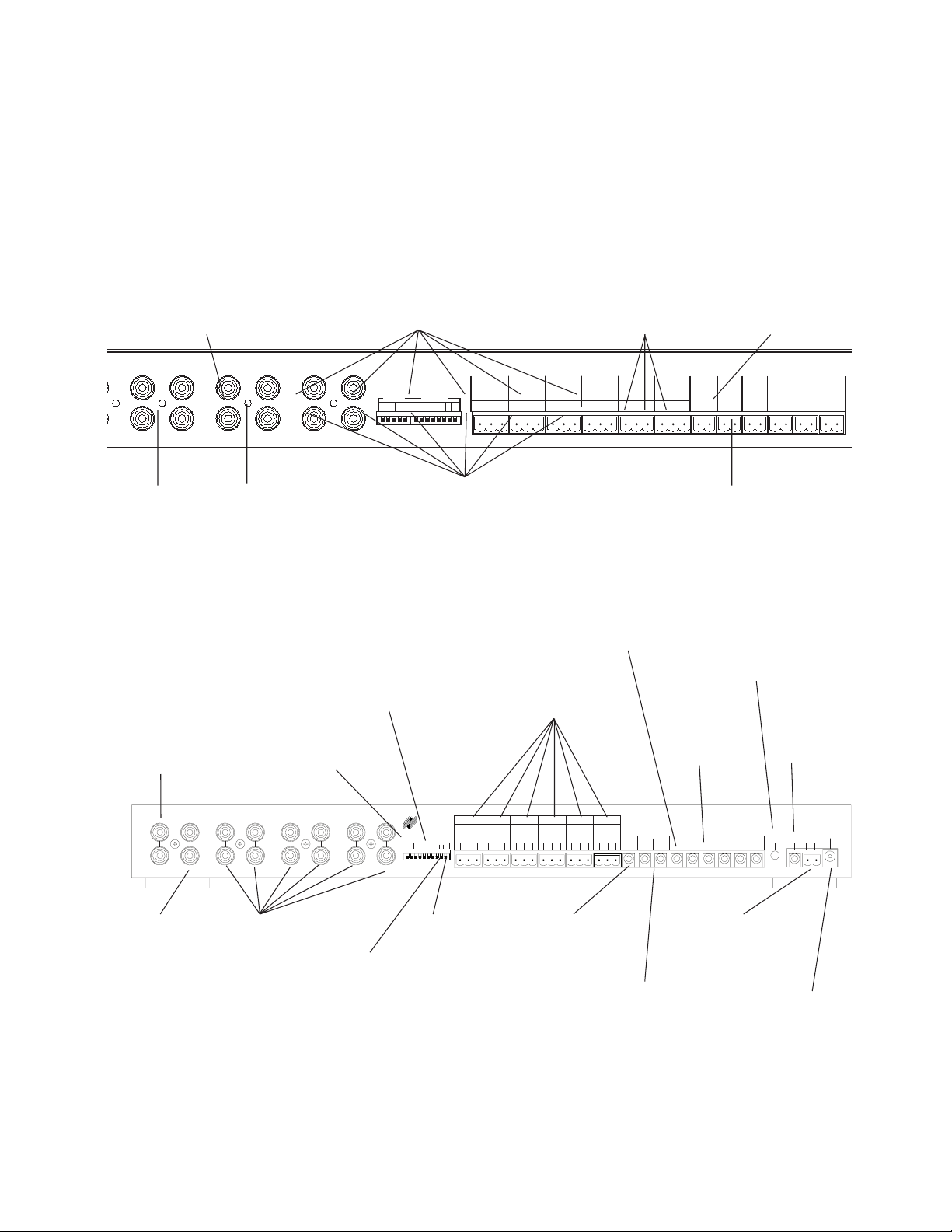
RCA Jack Input con-
nect to a record output,
a preamp output or a
multiroom output of
your preamp/receiver.
EYE DIP switch enables
the front panel IR sensor
CONTROL OUT
provides 12V DC
@ 200mA when
one or more
speakers are
turned on
POWER jack
for 16V AC
wall adapter
(included)
COMMON
FLASHER outputs
control components
which are common
to all MRZ-6’s in a
system
IR DATA IN and Out
connects to other IR sys-
tems (MRZ-6, IRP2+,
IRP6+, IRZ6+, etc.)
SENSOR/KEYPAD
connections corre-
sponding to each of
the Room line level
volume controls.
VOLUME DIP
chooses whether
all rooms will turn
on at 25% or at
the last volume
setting used
MODE switches control the
configuration of multiple MRZ-6’s
and the routing of IR Data
FLASHER level
adjusts the power
of all flashers
DEDICATED FLASHER
output controls compo-
nents which are dedicat-
ed to this MRZ-6
UART jack for ALL ON and
ALL OFF commands when
multiple MRZ-6’s are used
within one system
ALL-ON DIP switches enable you to select
which rooms are activated when the ALL-ON
command is issued
RCA Jack Cascade
Outputs
connect to the Inputs
of additional MRZ-6s.
RCA Jack Outputs
connect to the Inputs
of the power amplifiers for each room.
Figure 5 MRZ-6 features
ROOM SELECT buttons allow you to “select”
rooms singly or in combinations. Once a room(s) is
selected, you may control it with the ON/OFF and
VOLUME UP and VOLUME DOWN buttons
SYNC jack
for 12V DC
power status
from
preamp/receiver
NILES
Page 7
5
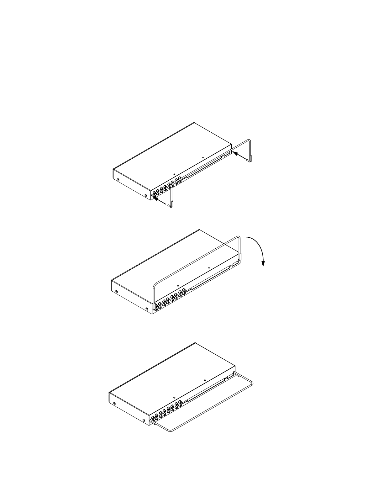
Using The Strain Relief Bar
Introduction — The Purpose of the Strain Relief Bar
The supplied steel bar attaches to the rear of the MRZ-6. By looping any cable around the strain relief bar before you
connect it to the MRZ-6, you relieve strain on the cables. Now, anytime you move the MRZ-6, you move the cables too
— no more accidental disconnects.
Installing the Strain Relief Bar
Figure 6 Rotate the bar until the ends line up with the two hole on the rear panel of the MRZ-6.
Figure 7 Insert the bar until the bend in the bar prevents any further insertion.
Figure 8 Rotate the bar until the welded stops reach the rear panel of the MRZ-6 and the bar is parallel to the shelf the MRZ-6 is sitting on.
Page 8
6
Audio connections
Introduction — The MRZ-6 Has Only One Input
An MRZ-6 has one set (left and right) of line-level inputs. All of the rooms connected to an MRZ-6 listen to the
same source. The MRZ-6 cannot switch between two sources (i.e., CD and Tuner) without some kind of outboard input switcher. Typically, the input switching you need is built into a preamp, receiver, or an IR controlled switching device. The two most popular methods of providing the input switching you need for your
multi-room system is to either purchase an infrared remote controlled preamp/receiver that is dedicated to the
multi-room system or to purchase an infrared remote controlled “two zone” preamp/receiver, using one zone
of the preamp/receiver for a home theater and the other zone to select sources for the MRZ-6.
In the following sections, only IR controlled input switching is discussed. This is because of the extensive
automation capabilities of the MRZ-6. Using an inexpensive manually controlled switcher for the MRZ-6 will
work sonically and electrically, but will not take advantage of the MRZ-6’s automation.
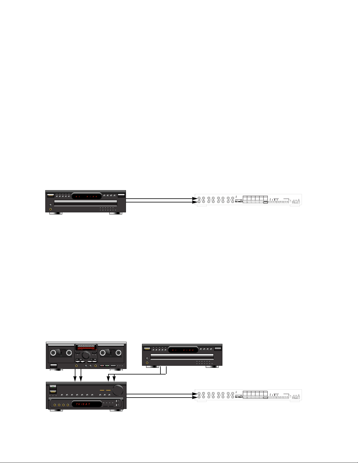
Connections for a System with Only One Source
An MRZ-6 has one set (left and right) of line-level inputs. If you have only one source (i.e., a CD player), its
line level outputs may be connected to the MRZ-6’s inputs via a stereo patch cable with RCA phono plugs on
both ends. See Figure 9.
Connections for a System with a Dedicated Preamp/Receiver or a Two Zone Preamp/Receiver
All of the source outputs are fed to the preamp/receiver’s inputs, the preamp/receiver selects a source and the
output is fed to the MRZ-6 input via a stereo patch cable with RCA phono plugs on both ends. If a “preamp
output” is used, the volume control of the preamp/receiver (a master volume for the entire system) must be permanently set to a high level (typically about 12 o’clock or 0dB) and never changed. Alternatively, a “tape output” or “record output” can be used, unless the preamp/receiver incorporates a record output selector switch
that does not respond to an infrared remote control for input selection. See Figure 10.
When a two zone preamp/receiver is used, all of the source outputs are fed to the two zone preamp/receiver’s
inputs, the home theater or main zone of the preamp/receiver selects a source for the home theater and the
second zone preamp of the preamp/receiver selects a source for the multiroom system. The second zone preamp output is fed to the MRZ-6 input via a stereo patch cable with RCA phono plugs on both ends. The volume control of the second zone of the preamp/receiver (the master volume for the entire system) must be permanently set to a high level (typically about 12 o’clock or 0dB) and never changed.
Figure 9 A Single Source Connected to an MRZ-6 system
COMMON
ZONE ALL ON
CTRL
OUT
POWER
16VAC
FLASHER
LEVEL
ADJUST
1
G
N
D
D
A
T
A
+
1
2
V
2
G
N
D
D
A
T
A
+
1
2
V
3
G
N
D
D
A
T
A
+
1
2
V
4
G
N
D
D
A
T
A
+
1
2
V
5
G
N
D
D
A
T
A
+
1
2
V
6
G
N
D
D
A
T
A
+
1
2
V
IN OUT
FLASHERSIR DATA
DEDICATED
12V
SYNC
IR SENSOR/KEYPAD INPUTS
VE
UART
+
-
MAIN
INPUT
ROOM 1
OUTPUT
ROOM 2
OUTPUT
ROOM 3
OUTPUT
ROOM 4
OUTPUT
ROOM 5
OUTPUT
ROOM 6
OUTPUT
LRLRL
R
L
R
CASCADE
OUTPUT
LRL
R
LRL
R
Niles Audio Corporation,Inc.
Miami, Florida USA
MODEL
MRZ-6
This device complies with part 15 of the FCC Rules. Operation is subject to the following two conditions: (1) This device may not cause
harmful interference, and (2) this device must accept any interference
received, including interference that may cause undesired operation.
Left Line-Level Audio
Right Line-Level Audio
Figure 10 Multiple Sources Connected to an MRZ-6 system Via a Preamp/Receiver
COMMON
ZONE ALL ON
CTRL
OUT
POWER
16VAC
FLASHER
LEVEL
ADJUST
1
G
N
D
D
A
T
A
+
1
2
V
2
G
N
D
D
A
T
A
+
1
2
V
3
G
N
D
D
A
T
A
+
1
2
V
4
G
N
D
D
A
T
A
+
1
2
V
5
G
N
D
D
A
T
A
+
1
2
V
6
G
N
D
D
A
T
A
+
1
2
V
IN OUT
FLASHERSIR DATA
DEDICATED
12V
SYNC
IR SENSOR/KEYPAD INPUTS
VE
UART
+
-
MAIN
INPUT
ROOM 1
OUTPUT
ROOM 2
OUTPUT
ROOM 3
OUTPUT
ROOM 4
OUTPUT
ROOM 5
OUTPUT
ROOM 6
OUTPUT
LRLRL
R
L
R
CASCADE
OUTPUT
LRL
R
LRL
R
Niles Audio Corporation,Inc.
Miami, Florida USA
MODEL
MRZ-6
This device complies with part 15 of the FCC Rules. Operation is subject to the following two conditions: (1) This device may not cause
harmful interference, and (2) this device must accept any interference
received, including interference that may cause undesired operation.
Left Line-Level Audio
Right Line-Level Audio
NILES
NILES
Page 9
7
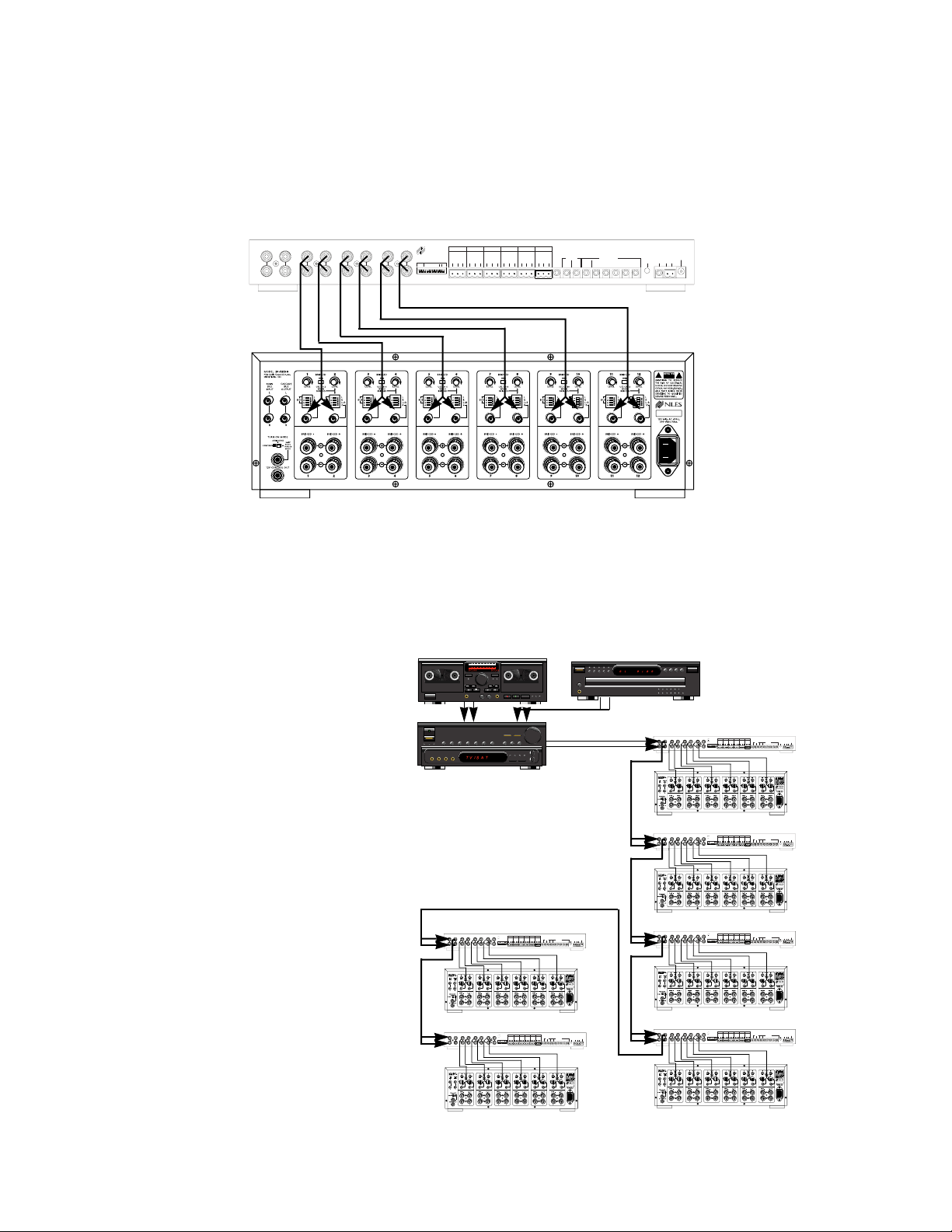
Output Audio Connections to Amplifiers
Every room output is connected to an amplifier channel. The ideal companion is the Niles SI-1230 twelve
channel amplifier. A stereo patch cable (with RCA phono plugs on both ends) is connected from each room
output to a grouped pair of inputs on the SI-1230. See Figure 11.
Expanding The System With Up To Six MRZ-6’s
In a system with more than six rooms, additional MRZ-6/SI-1230 combinations can be added, to a maximum
of six MRZ-6s (36 rooms) so that the ALL ON and ALL OFF commands will work reliably throughout the system. Two types of system design are supported with multiple MRZ-6 units as follows:
Single Zone
— One Master MRZ-6
And Up To Five Slave MRZ-6
Units
The MRZ-6 whose Input is connected to the Preamp/Receiver’s Output
is the Master . The cascade output of
the Master MRZ-6 is then connected to the input of the Slave MRZ-6.
Using the cascade output, each
Slave MRZ-6 input is connected to
the preceding MRZ-6. All On and
All Off commands will work reliably throughout the system. See
Figure 12.
Figure 11 Connecting a Niles SI-1230 12 channel amplifier to the MRZ-6
Figure 12
A Single Zone System With The
Maximum of Five Slave Units and
One Master MRZ-6
COMMON
ZONE ALL ON
CTRL
OUT
POWER
16VAC
FLASHER
LEVEL
ADJUST
1
G
N
D
D
A
T
A
+
1
2
V
2
G
N
D
D
A
T
A
+
1
2
V
3
G
N
D
D
A
T
A
+
1
2
V
4
G
N
D
D
A
T
A
+
1
2
V
5
G
N
D
D
A
T
A
+
1
2
V
6
G
N
D
D
A
T
A
+
1
2
V
IN OUT
FLASHERSIR DATA
DEDI-
CATED
12V
SYNC
IR SENSOR/KEYPAD INPUTS
VE
UART
+
-
MAIN
INPUT
ROOM 1
OUTPUT
ROOM 2
OUTPUT
ROOM 3
OUTPUT
ROOM 4
OUTPUT
ROOM 5
OUTPUT
ROOM 6
OUTPUT
LRL
R
L
R
L
R
CASCADE
OUTPUT
LRL
R
L
R
L
R
Niles Audio Corporation, Inc.
Miami, Florida USA
MODEL
MRZ-6
This device complies with part 15 of the FCC Rules. Operation is subject to the following two conditions: (1) This device may not cause
harmful interference, and (2) this device must accept any interference
received, including interference that may cause undesired operation.
COMMON
ZONE ALL ON
CTRL
OUT
POWER
16VAC
FLASHER
LEVEL
ADJUST
1
G
N
D
D
A
T
A
+
1
2
V
2
G
N
D
D
A
T
A
+
1
2
V
3
G
N
D
D
A
T
A
+
1
2
V
4
G
N
D
D
A
T
A
+
1
2
V
5
G
N
D
D
A
T
A
+
1
2
V
6
G
N
D
D
A
T
A
+
1
2
V
IN OUT
FLASHERSIR DATA
DEDICATED
12V
SYNC
IR SENSOR/KEYPAD INPUTS
VE
UART
+
-
MAIN
INPUT
ROOM 1
OUTPUT
ROOM 2
OUTPUT
ROOM 3
OUTPUT
ROOM 4
OUTPUT
ROOM 5
OUTPUT
ROOM 6
OUTPUT
LRLRLRL
R
CASCADE
OUTPUT
LRL
R
LRL
R
Niles Audio Corporation,Inc.
Miami, Florida USA
MODEL
MRZ-6
This device complies with part 15 of the FCC Rules. Operation is subject to the following two conditions: (1) This device may not cause
harmful interference, and (2) this device must accept any interference
received, including interference that may cause undesired operation.
Slave #1
Slave #2
Slave #4
Slave #5
Slave #3
Master MRZ-6
NILES
NILES
NILES
NILES
NILES
NILES
NILES
Page 10
8
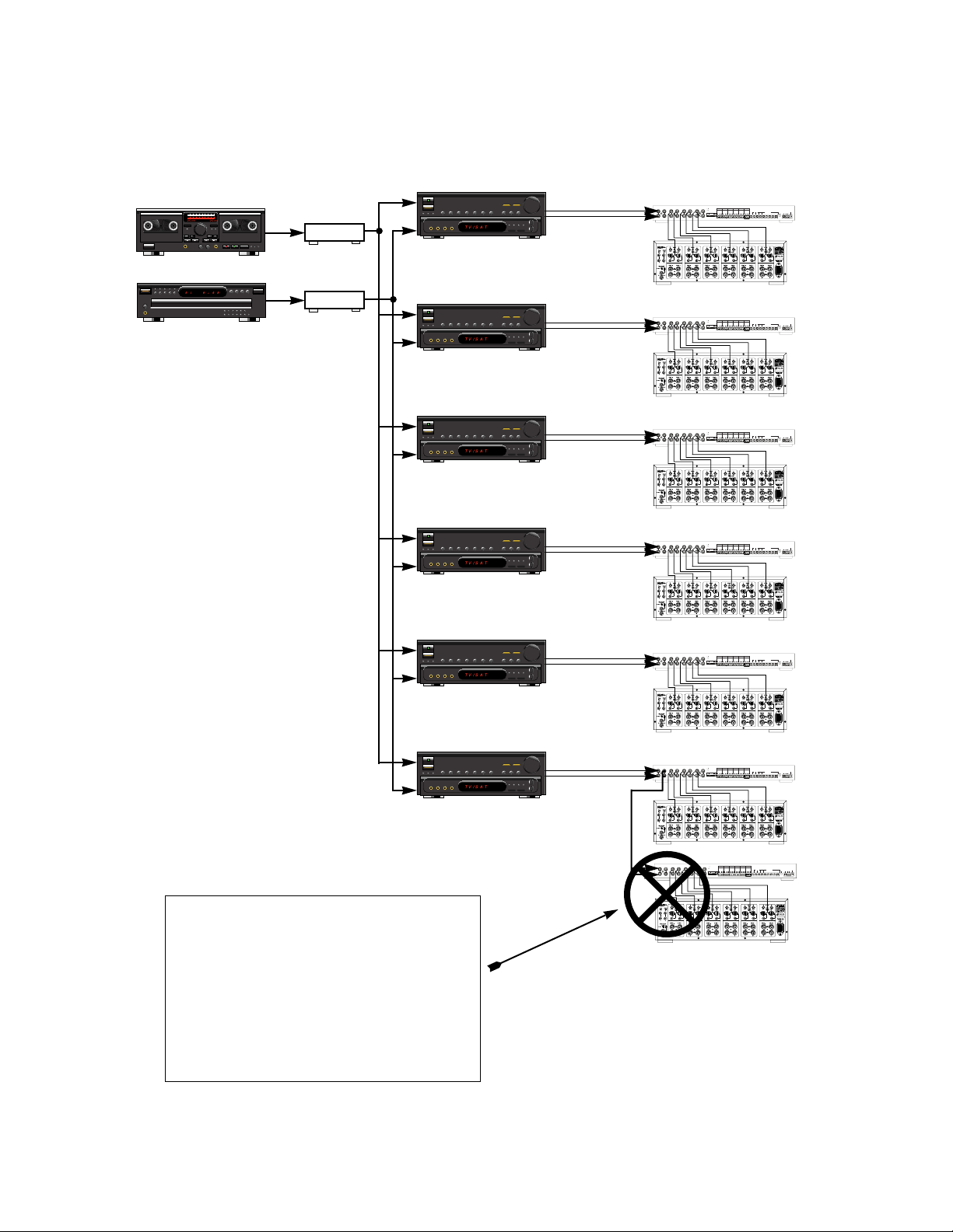
Multiple Zone System — Each Of Up To Six Master MRZ-6s Has Its Own Dedicated Preamp/Receiver
Each MRZ-6 is connected to its own dedicated preamp/receiver. All On and All Off commands will work reliably throughout the system. See Figure 13.
Figure 13
A Multiple Zone System With The
Maximum of Six Master MRZ-6
units. Each source is connected to a
Niles ADA-6 audio distribution
amp which connects to all six of
the Preamp/Receivers.
COMMON
ZONE ALL ON
CTRL
OUT
POWER
16VAC
FLASHER
LEVEL
ADJUST
1
G
N
D
D
A
T
A
+
1
2
V
2
G
N
D
D
A
T
A
+
1
2
V
3
G
N
D
D
A
T
A
+
1
2
V
4
G
N
D
D
A
T
A
+
1
2
V
5
G
N
D
D
A
T
A
+
1
2
V
6
G
N
D
D
A
T
A
+
1
2
V
IN OUT
FLASHERSIR DATA
DEDICATED
12V
SYNC
IR SENSOR/KEYPAD INPUTS
VE
UART
+
-
MAIN
INPUT
ROOM 1
OUTPUT
ROOM 2
OUTPUT
ROOM 3
OUTPUT
ROOM 4
OUTPUT
ROOM 5
OUTPUT
ROOM 6
OUTPUT
LRLRLRL
R
CASCADE
OUTPUT
LRL
R
LRL
R
Niles Audio Corporation,Inc.
Miami, Florida USA
MODEL
MRZ-6
This device complies with part 15 of the FCC Rules. Operation is subject to the following two conditions: (1) This device may not cause
harmful interference, and (2) this device must accept any interference
received, including interference that may cause undesired operation.
Master MRZ-6
Caution! In A Multiple Zone System With More
Than One Master MRZ-6, You Cannot Add Any
Slave MRZ-6 Units
Because of the nature of the communication protocol between MRZ-6 units, All On and All Off
commands will not work correctly and/or reliably
if you attempt to expand one of the multiple Master
MRZ-6s (each with its own dedicated
preamp/receiver) with an additional Slave MRZ-6.
Illegal Slave
ADA-6
ADA-6
NILES
NILES
NILES
NILES
NILES
NILES
IR SENSOR/KEYPAD INPUTS
This device complies with part 15 of the FCC Rules. Operation is sub-
MODEL
MAIN
CASCADE
INPUT
OUTPUT
LRL
R
ROOM 1
ROOM 2
ROOM 3
ROOM 4
OUTPUT
OUTPUT
OUTPUT
OUTPUT
LRLRLRL
LRL
R
ROOM 5
ROOM 6
OUTPUT
OUTPUT
1
2
3
4
NILES
+
+
+
+
D
D
D
D
G
G
G
G
A
A
A
A
1
1
1
1
N
N
N
N
T
T
T
T
2
2
2
2
D
D
D
D
A
A
A
A
V
V
V
V
ZONE ALL ON
VE
R
5
+
D
G
A
1
N
T
2
D
A
V
ject to the following two conditions: (1) This device may not cause
6
harmful interference, and (2) this device must accept any interference
received, including interference that may cause undesired operation.
+
D
G
A
1
N
T
2
D
A
V
12V
SYNC
IN OUT
MRZ-6
Niles Audio Corporation,Inc.
Miami, Florida USA
POWER
FLASHER
UART
16VAC
CTRL
LEVEL
FLASHERSIR DATA
OUT
ADJUST
+
-
DEDI-
COMMON
CATED
Page 11

9
Infrared Control Connections
Connecting to Room IR Sensor/Keypads Using the SENSOR Inputs
There are many ways to control your MRZ-6 system. Each location may have a different method depending upon the
level of control desired. You can choose from a basic preprogrammed keypad (RP-9 stock# FG00760), a Niles IR programmable keypad (IntelliPad stock# FG00634), or Niles IR sensors with a programmable learning remote control. One
keypad can be combined with one IR sensor within the same room. If a particular room requires two or more IR sensors or two or more keypads you should install a Niles XRP6+ IR Expansion Unit (Niles stock# FG00638).
A
voiding Interference
• Avoid locating any of the cables, sensors, keypads or the MRZ-6 near any potential sources of
ElectroMagnetic Interference (EMI) such as light dimmers, speed controls for ceiling fans, electrical ballasts,
television sets, large motors, heaters or air conditioners.
Room Status Feedback Signal
• When a particular room is on, the MRZ-6 outputs a status signal on the corresponding SENSOR input.
• The Niles IntelliPad utilizes this status signal to automate room turn-on and room turn-off.
• Three Niles IR sensors (IRR4D+, IRR4S+, and TIR1+) utilize the signal to indicate the room’s on/off status.
Recommended IR Sensor/Keypad Cable
• Each room must be home run (wired directly) to its assigned SENSOR input. See Figure 14.
• The MRZ-6 connects to IR sensors and keypads using 2-conductor shielded cable with a drain wire.
Recommended cables are “data grade” cables made of two 22 gauge (or larger) conductors surrounded by
a foil shield and a bare drain (ground) wire. Data grade cable provides the capability for runs of up to 500
feet to each sensor . Examples are W est Penn D291, Belden 8 7 61 or Carol C2516. Any 22 to 16 gauge 2-conductor shielded cable with a drain wire will accommodate 150 foot runs to each sensor and is available at
your local hardware or electrical supply store.
Making the IR Sensor/Keypad Connections
• CAUTION: Power to the MRZ-6 and amplifier must be disconnected.
• For your convenience, all SENSOR input connectors on the MRZ-6 are
removable.
• Strip 3/8” of insulation from the end of each wire. Tightly twist each wire
end until there are no frayed ends.
• Insert each wire into the appropriate hole on the connector terminals
using the sensor/keypad wiring convention. T ighten the screws which lock
the wire into place. Be certain that the polarity labels on the rear of the
MRZ-6 are precisely followed.
12
V
G
N
D
D
A
T
A
Red
Drain (shield)
Black
Pin 1= Red (+12v DC)
Pin 2= Bare (Ground)
Pin 3= Black (DATA)
Figure 14
Page 12

Distributing IR Commands Between Units
Using the IR DATA IN and IR DATA OUT
The IR DATA IN and IR DATA OUT jacks are used to cascade IR data (TTL level, active high) from one unit to the next.
• In a multiple MRZ-6 system, the Master MRZ-6 always receives the data coming in from the Slave MRZ-6
units. See Figure 15
• The ZONE DIP switches route IR data received at the MRZ-6’s IR DATA IN jack to the Dedicated flasher.
All data is passed to the Common flashers regardless of the DIP switch settings. See Figure 15, page 19 of
the MRZ-6 manual.
10
0
O
Figure 15 IR DATA Connections
Master
Slave #1
Slave #2
This device complies with part 15 of the FCC Rules. Operation is subject to the following two conditions: (1) This device may not cause
6
harmful interference, and (2) this device must accept any interference
received, including interference that may cause undesired operation.
D
+
G
A
1
N
T
2
D
A
V
+
1
2
V
+
1
2
V
DEDI-
12V
CATED
SYNC
IN OUT
This device complies with part 15 of the FCC Rules. Operation is subject to the following two conditions: (1) This device may not cause
6
harmful interference, and (2) this device must accept any interference
received, including interference that may cause undesired operation.
D
G
A
N
T
D
A
DEDI-
12V
CATED
SYNC
IN OUT
FLASHERSIR DATA
COMMON
FLASHERSIR DATA
COMMON
FLASHERSIR DATA
COMMON
MODEL
Niles Audio Corporation, Inc.
Miami, Florida USA
FLASHER
CTRL
LEVEL
OUT
ADJUST
MODEL
Niles Audio Corporation, Inc.
Miami, Florida USA
FLASHER
CTRL
LEVEL
OUT
ADJUST
MODEL
Niles Audio Corporation, Inc.
Miami, Florida USA
FLASHER
CTRL
LEVEL
OUT
ADJUST
MRZ-6
MRZ-6
MRZ-6
UART
+
-
UART
+
-
UART
+
-
POWER
16VAC
POWER
16VAC
POWER
16VAC
0 1
O O : 0 0
Page 13

Wiring Diagrams for Infrared Control
IR Connections for a System with a Dedicated Preamp/Receiver and one MRZ-6
As explained on page 6, a single zone system with one MRZ-6 will distribute the output of one Preamp/Receiver’s
selected audio source to each of its six outputs for amplification and individual volume control. See Figure 16.
• A 12V DC wall adapter is connected to the switched outlet of the Preamp/Receiver to provide sync (or
status) to the MRZ-6. This switched outlet may also be used to power up source components which have
latching power.
• Both ZONE DIP switches should be set to the UP (or single zone) position. All IR codes are passed through
both the MRZ-6’s Dedicated and Common flasher outputs.
• When using RP-9 keypads, all automation codes are taught to the MRZ-6.
For more information concerning IntelliPad®/MRZ-6 programming, see page 26 of the MRZ-6 manual.
11
0 1 0 : 0 0
O O : 0 0O O : 0 0
93.9 FM
STEREO
COMMON
ZONE ALL ON
CTRL
OUT
POWER
16VAC
FLASHER
LEVEL
ADJUST
1
G
N
D
D
A
T
A
+
1
2
V
2
G
N
D
D
A
T
A
+
1
2
V
3
G
N
D
D
A
T
A
+
1
2
V
4
G
N
D
D
A
T
A
+
1
2
V
5
G
N
D
D
A
T
A
+
1
2
V
6
G
N
D
D
A
T
A
+
1
2
V
IN OUT
FLASHERSIR DATA
DEDICATED
12V
SYNC
IR SENSOR/KEYPAD INPUTS
VE
UART
+
-
MAIN
INPUT
ROOM 1
OUTPUT
ROOM 2
OUTPUT
ROOM 3
OUTPUT
ROOM 4
OUTPUT
ROOM 5
OUTPUT
ROOM 6
OUTPUT
LRLRL
R
L
R
CASCADE
OUTPUT
LRL
R
LRL
R
Niles Audio Corporation,Inc.
Miami, Florida USA
MODEL
MRZ-6
This device complies with part 15 of the FCC Rules. Operation is subject to the following two conditions: (1) This device may not cause
harmful interference, and (2) this device must accept any interference
received, including interference that may cause undesired operation.
Figure 16 IR Connections for a System with a Dedicated Preamp/Receiver and one MRZ-6
To switched outlet
From tape or pre-out
Page 14

IR Connections for a System with a Dedicated Preamp/Receiver and up to six MRZ-6’s
As explained on page 7, a single zone system can be expanded to distribute a single source to up to 36 rooms using
six MRZ-6 units. See Figure 17
• A 12VDC wall adapter is connected to the switched outlet of the Preamp/Receiver to provide sync (or status) to the first (or Master) MRZ-6. This switched outlet may also be used to power up source components
which have latching power.
• The UART connection enables the Slave MRZ-6’s to power on the Preamp/Receiver using the automation
codes taught to the Master MRZ-6. The UART connection also enables All On and All Off control of all the
rooms in the system. See page 20 of the MRZ-6 manual.
• DATA OUT of the Slave MRZ-6’s is connected to the DATAIN of the Master via the DATA IN and DATA
OUT jacks. See Figure 15.
• Only the Master MRZ-6’s Dedicated flasher output is connected to the Preamp/Receiver’s front panel IR
sensor.
• When using RP-9 keypads, all automation codes are taught to the Master MRZ-6 only.
For more information concerning IntelliPad®/MRZ-6 programming, see page 26 of the MRZ-6 manual.
• Both ZONE DIPswitches should be set to the UP (or single zone) position. IR codes received at any of the
MRZ-6’s sensor inputs are passed through DATA IN and DATA OUT terminals and output via the Master
MRZ-6’s Dedicated and Common flasher outputs.
12
0 1 0 : 0 0
O O : 0 0O O : 0 0
93.9 FM
STEREO
COMMON
ZONE ALL ON
CTRL
OUT
POWER
16VAC
FLASHER
LEVEL
ADJUST
1
G
N
D
D
A
T
A
+
1
2
V
2
G
N
D
D
A
T
A
+
1
2
V
3
G
N
D
D
A
T
A
+
1
2
V
4
G
N
D
D
A
T
A
+
1
2
V
5
G
N
D
D
A
T
A
+
1
2
V
6
G
N
D
D
A
T
A
+
1
2
V
IN OUT
FLASHERSIR DATA
DEDI-
CATED
12V
SYNC
IR SENSOR/KEYPAD INPUTS
VE
UART
+
-
MAIN
INPUT
ROOM 1
OUTPUT
ROOM 2
OUTPUT
ROOM 3
OUTPUT
ROOM 4
OUTPUT
ROOM 5
OUTPUT
ROOM 6
OUTPUT
LRLRL
R
L
R
CASCADE
OUTPUT
LRL
R
LRL
R
Niles Audio Corporation,Inc.
Miami, Florida USA
MODEL
MRZ-6
This device complies with part 15 of the FCC Rules. Operation is subject to the following two conditions: (1) This device may not cause
harmful interference, and (2) this device must accept any interference
received, including interference that may cause undesired operation.
Figure 17 IR Connections for a System with a Dedicated Preamp/Receiver and up to six MRZ-6’s
From tape or pre-out Master MRZ-6
Slave MRZ-6
To switched outlet
Page 15

IR Connections for a System with a Dual Zone Receiver and a single MRZ-6
As explained on page 6, a dual zone receiver can be used to independently control source selection for both a home
theater and a multi-room sound system with a MRZ-6. See Figure 18.
• If an IR sensor is required to operate the main zone of the home theater, a sensor must be connected to a
Niles IR Main System Unit with a flasher to control the main zone via the Preamp/Receiver’s front panel.
The IRPunit’s DA TA OUT is connected to the MRZ-6’s DA T AIN jack to enable control of the sources shared
by both the home theater and the multi-room sound system via the MRZ-6’s repeater system.
• Both ZONE DIP switches should be set to the DOWN (or multi-zone) position. In this position, IR commands passed from other MRZ-6’s (or in this case, commands received from the home theater’s IR main system unit and received at the MRZ-6’s IR DATA IN jack) will not be routed to the Dedicated flasher. This
enables the same codes to be used for the main and second zones independent of each other, while the
commands used to control the shared source components are output via the MRZ-6’s Common flasher outputs.
13
0 1 0 : 0 0
O O : 0 0O O : 0 0
93.9 FM
STEREO
COMMON
ZONE ALL ON
CTRL
OUT
POWER
16VAC
FLASHER
LEVEL
ADJUST
1
G
N
D
D
A
T
A
+
1
2
V
2
G
N
D
D
A
T
A
+
1
2
V
3
G
N
D
D
A
T
A
+
1
2
V
4
G
N
D
D
A
T
A
+
1
2
V
5
G
N
D
D
A
T
A
+
1
2
V
6
G
N
D
D
A
T
A
+
1
2
V
IN OUT
FLASHERSIR DATA
DEDICATED
12V
SYNC
IR SENSOR/KEYPAD INPUTS
VE
UART
+
-
MAIN
INPUT
ROOM 1
OUTPUT
ROOM 2
OUTPUT
ROOM 3
OUTPUT
ROOM 4
OUTPUT
ROOM 5
OUTPUT
ROOM 6
OUTPUT
LRLRL
R
L
R
CASCADE
OUTPUT
LRL
R
LRL
R
Niles Audio Corporation,Inc.
Miami, Florida USA
MODEL
MRZ-6
This device complies with part 15 of the FCC Rules. Operation is subject to the following two conditions: (1) This device may not cause
harmful interference, and (2) this device must accept any interference
received, including interference that may cause undesired operation.
Figure 18 IR Connections for a System with a Dual Zone Receiver and a single MRZ-6
From Multiroom pre-out
To switched outlet
To Multiroom IR input
Home Theater Sensor
From DATA OUT
Page 16

IR Connections for a System with a Dual Zone Receiver and up to six MRZ-6’s
This system is very similar to the dual zone/single MRZ-6 system. The dual zone receiver may be used to independently control source selection for both a home theater and a multi-room sound system of up to 36 rooms with six
MRZ-6’s. See Figure 19.
• It is not necessary to sync the Preamp/Receiver if the second zone has dedicated "on" and "off" commands
or can be activated with an input select command. Note: If the dual zone receiver you are using has a control voltage output or a switched outlet which is active ONL Ywhen the second zone is on, the second zone
may be synced. However, if the second zone does not have discrete "on" and "off" commands, or the ability to turn on with an input select command as described above, the receiver cannot be automated.
• If an IR sensor is required to operate the main zone of the home theater, a sensor must be connected to a
Niles IR Main System Unit with a flasher to control the main zone via the receiver’s front panel. The IRP
Main System Unit’s DATA OUT is connected to the Slave MRZ-6’s DATA IN jack to enable control of the
sources shared by both the home theater and the multiroom system via the MRZ-6’s repeater system.
• Both ZONE DIPswitches on both MRZ-6’ s should be set to the DOWN (or multi-zone) position. In this configuration, IR commands issued from the home theater will not be routed to either MRZ-6’s Dedicated flasher. This enables identical Preamp/Receiver commands to be used for both the home theater and the multiroom sound systems independently, while the commands used to control the shared sources are output via
the Master MRZ-6’s Common flasher outputs.
• The DATA OUT of the Slave MRZ-6’s is connected to the Master MRZ-6 via the DATA IN and DATA OUT
jacks. See Figure 15.
• The UART connection enables the Slave MRZ-6’s to power on the Preamp/Receiver using the automation
codes taught to the Master MRZ-6. The UART connection also enables All On and All Off control of all the
rooms in the system. See page 20 of the MRZ-6 manual.
• If IntelliPads or IR sensors are used with or without RP-9 keypads, the Master and all additional Slave MRZ6’s Dedicated flasher outputs must be tied together to enable access to the receiver’s second zone IR input.
Note: It is not necessary to diode isolate the MRZ-6’s Dedicated flasher outputs.
For more information concerning IntelliPad®/MRZ-6 programming, see page 26 of the MRZ-6 manual.
14
0 1 0 : 0 0
O O : 0 0O O : 0 0
93.9 FM
STEREO
COMMON
ZONE ALL ON
CTRL
OUT
POWER
16VAC
FLASHER
LEVEL
ADJUST
1
G
N
D
D
A
T
A
+
1
2
V
2
G
N
D
D
A
T
A
+
1
2
V
3
G
N
D
D
A
T
A
+
1
2
V
4
G
N
D
D
A
T
A
+
1
2
V
5
G
N
D
D
A
T
A
+
1
2
V
6
G
N
D
D
A
T
A
+
1
2
V
IN OUT
FLASHERSIR DATA
DEDICATED
12V
SYNC
IR SENSOR/KEYPAD INPUTS
VE
UART
+
-
MAIN
INPUT
ROOM 1
OUTPUT
ROOM 2
OUTPUT
ROOM 3
OUTPUT
ROOM 4
OUTPUT
ROOM 5
OUTPUT
ROOM 6
OUTPUT
LRLRL
R
L
R
CASCADE
OUTPUT
LRL
R
LRL
R
Niles Audio Corporation,Inc.
Miami, Florida USA
MODEL
MRZ-6
This device complies with part 15 of the FCC Rules. Operation is subject to the following two conditions: (1) This device may not cause
harmful interference, and (2) this device must accept any interference
received, including interference that may cause undesired operation.
Figure 19 IR Connections for a System with a Dual Zone Receiver and up to six MRZ-6’s
From Multiroom pre-out
Master MRZ-6
Slave MRZ-6
Home
Theater
Sensor
From DATA
OUT
To switched outlet
To Multiroom IR input
To DATA IN
Page 17

IR Connections for a System with two or more Preamp/Receivers and MRZ-6’s
This system is very similar to the single zone receiver/single MRZ-6 system. See Figure 20.
• A 12VDC wall adapter is connected to the switched outlet of each of the Preamp/Receivers to provide sync
(or status) to their MRZ-6.
• The CONTROL OUT of each MRZ-6 is connected to the input of the AC-3 which is used to power up those
shared sources which have latching power.
Note: The MRZ-6 is diode isolated internally, blocking diodes
are not required.
• DATA OUT of the Slave is connected to the DAT AIN of the Master. The Slave will pass IR data to the Master
for control of the shared sources via the Master’s common flasher outputs. See Figure 15.
• The UART connection enables All On and All Off control of all the rooms in the system. See page 20 of the
MRZ-6 manual.
• Both ZONE DIP switches should be set to the DOWN (or multi-zone) position. In this position, IR commands passed through the other MRZ-6’s will not be routed to the Dedicated flasher. This enables identical
Preamp/Receiver commands to be used for both the home theater and the multi-room sound systems independently, while the commands used to control the shared sources are output via the Master MRZ-6’s
Common flasher outputs.
• When using RP-9 keypads with or without IntelliPads or IR sensors, all automation codes are taught to both
MRZ-6’s.
For more information concerning IntelliPad®/MRZ-6 programming, see page 126of MRZ-6 manual.
15
0 1 0 : 0 0
O O : 0 0O O : 0 0
93.9 FM
STEREO
93.9 FM
STEREO
COMMON
ZONE ALL ON
CTRL
OUT
POWER
16VAC
FLASHER
LEVEL
ADJUST
1
G
N
D
D
A
T
A
+
1
2
V
2
G
N
D
D
A
T
A
+
1
2
V
3
G
N
D
D
A
T
A
+
1
2
V
4
G
N
D
D
A
T
A
+
1
2
V
5
G
N
D
D
A
T
A
+
1
2
V
6
G
N
D
D
A
T
A
+
1
2
V
IN OUT
FLASHERSIR DATA
DEDICATED
12V
SYNC
IR SENSOR/KEYPAD INPUTS
VE
UART
+
-
MAIN
INPUT
ROOM 1
OUTPUT
ROOM 2
OUTPUT
ROOM 3
OUTPUT
ROOM 4
OUTPUT
ROOM 5
OUTPUT
ROOM 6
OUTPUT
LRLRL
R
L
R
CASCADE
OUTPUT
LRL
R
LRL
R
Niles Audio Corporation,Inc.
Miami, Florida USA
MODEL
MRZ-6
This device complies with part 15 of the FCC Rules. Operation is subject to the following two conditions: (1) This device may not cause
harmful interference, and (2) this device must accept any interference
received, including interference that may cause undesired operation.
IN OUT
+ — + —
Figure 20 IR Connections for a System with two or more Preamp/Receivers and MRZ-6’s
From tape or pre-out
To switched outlet
To CONTROL IN
To switched outlet
From tape or pre-out
Slave MRZ-6
Master MRZ-6
Niles AC-3
Page 18

IR Connections for a System with two Dual Zone Receivers and multiple MRZ-6’s
This system is very similar to the dual zone receiver/single MRZ-6 system. Two separate home theaters and two separate zones of multi-room sound may be controlled independently. See Figure 21.
• It is not necessary to sync the receiver if the second zone has dedicated “on” and “off” commands or can
be activated with an input select command. Note: If the dual zone receiver you are using has a control voltage output or a switched outlet which is active ONLY when the second zone is on, the second zone may
be synced. However, if the second zone does not have discrete "on" and "off" commands, or the ability to
turn on with an input select command as described above, the receiver cannot be automated.
• If IR sensors are required to operate the main zone of the home theaters, sensors must be connected to an
IRZ-6+ IR Main System Unit with flashers to control the home theaters via their receivers front panel.
• IR sensors and an IRZ-6+ are used to enable control of the main zones of each receiver via the IRZ’s
Dedicated flasher outputs to their front panels.
• The DATA OUT of the IRZ-6+ is connected to the DATA IN of the first Slave MRZ #1. The DATA IN/OUT
connections of the other MRZ-6’s connect to the Master MRZ-6 #3 which flashes the source components
via its Common flasher outputs.
• The UART connection enables the Slave MRZ-6’s to power on the Preamp/Receiver using the automation
codes taught to the Master MRZ-6. The UART connection enables All On and All Off commands to control
all of the rooms common to Master MRZ-6 #3 and Slave MRZ-6 #2 only. For more information, see page 8
of the MRZ-6 manual.
16
0 1 0 : 0 0
O O : 0 0O O : 0 0
93.9 FM
STEREO
93.9 FM
STEREO
COMMON
ZONE ALL ON
CTRL
OUT
POWER
16VAC
FLASHER
LEVEL
ADJUST
1
G
N
D
D
A
T
A
+
1
2
V
2
G
N
D
D
A
T
A
+
1
2
V
3
G
N
D
D
A
T
A
+
1
2
V
4
G
N
D
D
A
T
A
+
1
2
V
5
G
N
D
D
A
T
A
+
1
2
V
6
G
N
D
D
A
T
A
+
1
2
V
IN OUT
FLASHERSIR DATA
DEDICATED
12V
SYNC
IR SENSOR/KEYPAD INPUTS
VE
UART
+
-
MAIN
INPUT
ROOM 1
OUTPUT
ROOM 2
OUTPUT
ROOM 3
OUTPUT
ROOM 4
OUTPUT
ROOM 5
OUTPUT
ROOM 6
OUTPUT
LRLRL
R
L
R
CASCADE
OUTPUT
LRL
R
LRL
R
Niles Audio Corporation,Inc.
Miami, Florida USA
MODEL
MRZ-6
This device complies with part 15 of the FCC Rules. Operation is subject to the following two conditions: (1) This device may not cause
harmful interference, and (2) this device must accept any interference
received, including interference that may cause undesired operation.
COMMON
ZONE ALL ON
CTRL
OUT
POWER
16VAC
FLASHER
LEVEL
ADJUST
1
G
N
D
D
A
T
A
+
1
2
V
2
G
N
D
D
A
T
A
+
1
2
V
3
G
N
D
D
A
T
A
+
1
2
V
4
G
N
D
D
A
T
A
+
1
2
V
5
G
N
D
D
A
T
A
+
1
2
V
6
G
N
D
D
A
T
A
+
1
2
V
IN OUT
FLASHERSIR DATA
DEDICATED
12V
SYNC
IR SENSOR/KEYPAD INPUTS
VE
UART
+
-
MAIN
INPUT
ROOM 1
OUTPUT
ROOM 2
OUTPUT
ROOM 3
OUTPUT
ROOM 4
OUTPUT
ROOM 5
OUTPUT
ROOM 6
OUTPUT
LRLRL
R
L
R
CASCADE
OUTPUT
LRL
R
LRL
R
Niles Audio Corporation,Inc.
Miami, Florida USA
MODEL
MRZ-6
This device complies with part 15 of the FCC Rules. Operation is subject to the following two conditions: (1) This device may not cause
harmful interference, and (2) this device must accept any interference
received, including interference that may cause undesired operation.
IN OUT
+ — + —
Figure 21 IR Connections for a System with two Dual Zone Receivers and multiple MRZ-6’s
From Multiroom pre-out
To switched outlet
To CONTROL IN
To switched outlet
From Multiroompre-out
Master MRZ-6
Slave MRZ-6
Niles AC-3
Master MRZ-6
To Multiroom IR input
To Multiroom IR input
Home
Theater
Sensor
#1
Home
Theater
Sensor
#2
#1
#2
#3
Page 19

• Both ZONE DIP switches should be set to the DOWN (or multi-zone) position. In this position, IR commands issued from the home theater sensor will not be routed to the Dedicated flasher. This enables identical Preamp/Receiver commands to be used for both the home theater and the multi-room sound systems
independently, while the commands used to control the shared sources are output via Master MRZ-6 #3’s
Common flasher outputs.
• The CONTROL OUT of each MRZ-6 is connected to the input of the AC-3 which can be used to power up
those shared sources which have latching power.
Note: The MRZ-6 is diode isolated internally; blocking
diodes are not required.
17
Page 20

18
Controlling Components Using the IR FLASHER Outputs
The IR flasher outputs on the MRZ-6 are used to drive Niles IR flashers which retransmit the IR commands that control
your remote controllable components. The MRZ-6 is equipped with two types of flasher outputs, a DEDICATED
FLASHER output and a COMMON FLASHER output. Use Niles IRC-2P MicroFlashers with the MRZ-6, they are
equipped with a 3.5 mono mini-plug.
DEDICA
TED FLASHER Output
• The DEDICATED FLASHER outputs only the IR commands received from this particular MRZ-6; it is gener -
ally used for control of a receiver or pre-amp dedicated to this particular MRZ-6.
• A DIP switch on the rear panel of the MRZ-6 transforms the DEDICATED FLASHER into a COMMON
FLASHER. This is useful when a large single zone system is created using one preamp/receiver to select
sources and multiple MRZ-6s to control room volume. Achange of input from any room will change the
input of the preamp/receiver if the dedicated flasher is transformed into a common flasher via the ZONE
dipswitch. See Page 19.
COMMON FLASHER
Output
• The COMMON FLASHER outputs IR commands received from any MRZ-6 linked via the IR DATA IN and
OUTS.
Making the IR Flasher Connections
• CAUTION: Power to the MRZ-6 and amplifier must be disconnected.
• For your convenience, all FLASHER output connectors on the MRZ-6 are jacks, use the Niles IRC-2P
MicroFlasher
TM
, since utilizes a 3.5 mono mini plug.
• Observe proper polarity when extending the IR flasher wire.
• To extend the flasher cable, use unshielded, two-conductor 16 gauge cable (“zip-cord”). Flasher cable can
be extended up to 200 feet.
Connecting T
wo Flashers to a Single Flasher Output
• After cutting off the plugs and stripping the wire ends of two IRC-2P flashers, use crimp caps, wire nuts or
solder to connect the negative of one flasher to the positive of the next flasher (this creates a “series” circuit),
then connect one of the plugs (observing correct polarity), and inserting the plug into an MRZ-6 flasher jack.
An MRZ-6 FLASHER output allows a maximum of two
IRC-2P MicroFlashers to be connected if they are
wired in series.
Page 21

19
Setting the DIP Switches
The ZONE DIP Switch
In a single zone system (a system with one preamp/receiver selecting
sources), both the Zone switches are in the UP position. In this position, if
additional MRZ-6’s are added to the system, the IR commands from other
MRZ-6’s will be routed to the Dedicated Flasher.
In a multiple zone system, both the switches are set to the DOWN position.
In this position, the IR commands from other MRZ-6’ s will not be routed to
the dedicated flasher, enabling identical preamp/receivers to be simultaneously controlled by each MRZ-6. See Figure 22.
Setting the DEFAULT DIP Switches
The DEFAULT DIP switches are used to configure various features of the MRZ-6.
Choosing Rooms That Respond T
o An ALL ON Command
The DIP switches labeled ALL ON enable you to individually configure which rooms will respond to the ALL
ON command. See Figure 23. Each room has a corresponding DIP switch (1-6 starting from the left).
• Setting the ALL ON DIP switch in the up
position will
enable the corresponding room control module to
respond to an ALL ON command.
• Setting the ALL ON DIP switch in the down
position will
disable the corresponding room control module from
responding to an ALL ON command.
Setting the T
urn-On Volume Level
The DIP switch labeled V enables you configure the volume level when
a room is turned on. See Figure 24.
• Setting the V DIP switch in the up
position will enable a room, when
turned on, to automatically revert to its previous volume level.
• Setting the V DIP switch in the down
position will enable a room,
when turned on, to automatically play at 25% of the maximum
volume level.
Enabling/Disabling the MRZ-6’
s Built-In IR Sensor
In some installations, having the built-in IR sensor enabled will cause a
feedback loop. The DIP switch labeled E disables the MRZ-6 sensor.
See Figure 25.
• Setting the E DIP switch in the up
position enables the IR sensor.
• Setting the E DIP switch in the down
position disables the IR sensor.
Controls DA
to DEDICAT
control module
Figure 22 In a single zone system, both Zone
DIP switches are in the UP position.
Multi Zone
Both switches
are in the
DOWN position.
Single Zone
Both switches
are in the UP
position.
UP = Responds To ALL ON
DOWN = Ignores ALL On
Figure 23 ALL ON respond DIP switches.
1 2 3 4 5 6
Turn on with last volume setting
Turn on with 25% volume
Figure 24 Turn-on volume level.
Enables built-in IR sensor
Disables built-in IR sensor
Figure 25 Enable/Disable switch for
MRZ-6’s IR Sensor
Page 22

20
Final Connections
Automating Your System Using the CONTROL OUT
• The CONTROL OUT supplies a constant 12V DC (maximum of a 200mAdraw) when any of the rooms
are on. A Niles voltage activated power strip can be triggered by this voltage.
• When an All Off command is received the MRZ-6 will turn off the 12V DC after a 3 second delay.
Distributing System-Wide Commands Using the UART Connector
• The UART connector distributes the ALL ON and ALL OFF commands to all MRZ-6’s in the system by connecting in parallel using two-conductor 20 gauge cable. Connect pin one to pin one and pin two to pin two.
Wiring runs should not exceed three feet in length.
Powering Y our MRZ-6
• The MRZ-6 is powered by plugging the 16V AC, 1.8 amp wall adapter (included) into the POWER jack.
Programming and Automating Your System
Introduction
The MRZ-6 is capable of learning the basic commands for your preamp/receiver, and issuing them in an intelligent
macro or sequence. This occurs when either the “CD” or the “Tuner” button is pressed on an RP-9 keypad or the Niles
“CD” or “Tuner” IR command is issued by a learning remote control and received by a sensor attached to an MRZ-6.
Additionally , special Niles IR commands are built into the MRZ-6 which enable automation systems and learning remote
controls to control the MRZ-6 in very specific ways. In order to take advantage of all of these features, you must synchronize the preamp/receiver, teach the MRZ-6 the six or seven IR commands to control the Preamp/receiver, and then
teach any learning remote controls or IntelliPads the special Niles automation IR codes.
Synchronizing the Preamp/Receiver
The MRZ-6 must “know” whether the preamp/receiver is
on or off so that it can correctly decide when to issue the
preamp/receiver’s “power” command. Typically, you
synchronize the preamp/receiver to the MRZ-6 by connecting a 12V DC wall adapter to the preamp/receiver’s
switched outlet, then connecting the 12V DC output to
the MRZ-6 SYNC input. See Figure 26. Now, whenever
the preamp/receiver is on, the MRZ-6 detects 12V DC at
the sync connector; likewise, when the preamp/receiver
is off, the MRZ-6 detects nothing at the sync connector.
This enables the MRZ-6 to make intelligent choices. For
example, if you press the CD button, the MRZ-6 checks the
sync port, sees that the preamp/receiver is already on, so it makes the intelligent decision; it does not issue the power
command, it simply reissues the CD input command and the CD play command. Every time the end user issues a command via remote or keypad, the MRZ-6 will synchronize the preamp/receiver as necessary.
Figure 26
12V DC Sync From
a Preamp/Receiver
COMMON
ALL ON
CTRL
OUT
POWER
16VAC
FLASHER
LEVEL
ADJUST
1
G
N
D
D
A
T
A
+
1
2
V
2
G
N
D
D
A
T
A
+
1
2
V
3
G
N
D
D
A
T
A
+
1
2
V
4
G
N
D
D
A
T
A
+
1
2
V
5
G
N
D
D
A
T
A
+
1
2
V
6
G
N
D
D
A
T
A
+
1
2
V
IN OUT
FLASHERSIR DATA
DEDICATED
12V
SYNC
IR SENSOR/KEYPAD INPUTS
VE
NILES
UART
+
-
Niles Audio Corporation, Inc.
Miami, Florida USA
MODEL
MRZ-6
This device complies with part 15 of the FCC Rules. Operation is subject to the following two conditions: (1) This device may not cause
harmful interference, and (2) this device must accept any interference
received, including interference that may cause undesired operation.
Page 23

21
Teaching the MRZ-6 the Preamp/Receiver, Tuner and CD Player IR Commands
The MRZ-6 is capable of learning IR commands to control the preamp/receiver, the tuner and the CD player. Once your
MRZ-6 has learned these IR commands, you can trigger intelligent sequences/macros by sending the MRZ-6 a Niles IR
command from a Niles RP-9 Keypad or a learning remote via a Niles IR sensor. To teach the preamp/tuner/CD player IR
commands to the MRZ-6 you need to do the following:
1) Assemble all of the original remote controls for the components in front of you.
2) Insert new, fresh batteries for the remote controls (This is very important, remote controls with weak batteries may operate the components but cannot teach learning devices correctly).
3) Check that the EYE DIP switch is in the enabled or UP position.
4) Place the T
EACH THE MRZ-6 template so that the buttons and LED’s are revealed through the cutouts in the
template. See Figure 27.
5) Press and hold the CD I
NPUT button for at least two seconds, then, while you continue to press and
hold the CD I
NPUT button, tap the TUNER FAVORITE STATION button. Release both buttons. The six
LED’s in the center of the front panel should blink twice in unison, then the S
ELECT LED lights.
6) Press the key that is labeled on the template for the command you want to teach the MRZ-6. The
L
EARN LED will light, confirming that the MRZ-6 is ready to learn an IR command.
7) Place the remote control one inch in front of the learning pinhole pointed straight towards the pin-
hole. Tap the key you want to teach to the MRZ-6. Do not press and hold, the MRZ-6 will use up
too much memory if you do. After a slight delay, you will see the L
EARN LED go out and the SELECT
LED turn on again. This indicates that an IR command has been learned and the MRZ-6 is ready
for you to select a new key.
8) Repeat steps 6 and 7 until all commands are taught. To return to normal operating mode press the
E
XIT button.
Note on Reteaching and Erasing: The IR commands taught to the MRZ-6 are stored in non-volatile Flash
memory in an uncompressed format, they cannot be erased with a power failure. Because no compression is
used, the MRZ-6 will learn IR commands that other learning remotes cannot learn, however, sometimes you
must reteach a command to get it right. If a particular IR code has to be relearned, simply press the problem
button when the S
ELECT LED is lit. Once the Learn LED lights, reteach the IR code. You do not have to reteach
any other codes.
If you teach a code to a button that you decide should have NO code, you can erase the code by reselecting
the button, and when the MRZ-6 lights up the L
EARN LED, simply press the EXIT button, the SELECT LED will
light and the button will be erased.
MRZ6 Multiroom Zone Controller
POWER OR
DISCRETE
ON
OFF
CD INPUT
SELECT LED
CD PLAY CD SKIP
(FUTURE USE ONLY)
TUNER INPUT TUNER FAVORITE
STATION
TUNER SKIP
(FUTURE USE ONLY)
Place the remote one inch in front
of this learning pinhole.
ENTER this mode by pressing and holding the CD Input button
for 2 seconds and tapping the Tuner Favorite Station.
EXIT
LEARNING MODE
TEACH THE MRZ-6
LEARN LED
LEARNING SENSOR
PINHOLE
USE THIS TEMPLATE TO TEACH THE MRZ-6
THE IR COMMANDS FOR THE PREAMP/
RECEIVER, THE CD PLAYER AND THE TUNER
STEP 1 Press and Hold the CD INPUTbutton for 2 sec-
onds. While still holding the CD IINPUTbutton, tap the
TUNERFAVORITE STATIONbutton.
STEP 2 The six LED’s in the center of the front panel will
blink twice, then the SELECTLED will light confirming that
the MRZ-6 is ready for you to select a key.
STEP 3 Press the key you wish to teach. The LEARNLED
will blink confirming that the MRZ-6 is ready to learn IR
commands.
STEP 4 Tap the key on the remote that you are teaching
from. The SELECTLED will light when the IRcommand is
learned. Continue steps 2 and 3 as required. To return to
operating mode press the EXITbutton.
‚
©1998 Niles Audio Corporation, Inc. All rights reserved. Niles and the Niles logo are regis-
ROOM
ON/OFF
ROOM
VOLUME
DOWN
ROOM
VOLUME
UP
CD ON CD ALL ON TUNER ON TUNER ALL ROOM ON ROOM OFF
ENTERand EXIT this mode by pressing and holding the CD On
button for 2 seconds and tapping the Room Off button.
TEACH A REMOTE
OR A KEYPAD
NILES
USE THIS TEMPLATE TO TEACH A LEARNING
REMOTE OR KEYPAD THE IR COMMANDS
WHICH CONTROL THE MRZ-6
STEP 1 Press and hold the CD O
N
button for 2 seconds.
While still holding the CD O
N
button, tap the Room Off
button.
STEP 2 The six LED’s in the center of the front panel will
cycle back and forth in a repeating pattern, confirming
that the MRZ-6 is ready for you to select a key.
STEP 3 Place the learning remote/keypad in front of the
teaching flasher. Press the key corresponding to the IR
command you wish to teach.The IR command will be
issued as long as you press the key.
STEP 5 When you are finished teaching IR codes to the
learning remote, repeat step one to exit back to normal
operating mode.
Place your learning remote or keypad
one inch in front of this teaching LED.
‚
Figure 27 Fold the Template and place the TEACH THE MRZ-6 side over the buttons and LED’s of the front panel.
TEACH THE MRZ-6
LEARNING SENSOR
PINHOLE
of this learning pinhole.
USE THIS TEMPLATE TO TEACH THE MRZ-6
THE IR COMMANDS FOR THE PREAMP/
RECEIVER, THE CD PLAYER AND THE TUNER
SELECT LED
CD INPUT
STEP 1 Press and Hold the CD INPUT
onds. While still holding the CD I
UNER F
T
AVORITE STATION button.
CD PLAY CD SKIP
ENTER this mode by pressing and holding the CD I
for 2 seconds and tapping the TUNER FAVORITE STATION.
button for 2 sec-
INPUT
button, tap the
(FUTURE USE ONLY)
Place the remote one inch in front
STEP 2 The six LED’s in the center of the front panel will
blink twice, then the S
the MRZ-6 is ready for you to select a key.
TUNER INPUT TUNER FAVORITE
NPUT button
ELECT
LED will light confirming that
STATION
TUNER SKIP
(FUTURE USE ONLY)
STEP 3 Press the key you wish to teach. The L
will blink confirming that the MRZ-6 is ready to learn IR
commands.
LEARN LED
POWER OR
DISCRETE
ON
NILES
EARN
OFF
STEP 4 Tap the key on the remote that you are teaching
LED
from. The S
learned. Continue steps 2 and 3 as required. To return to
operating mode press the
LEARNING MODE
©1998 Niles Audio Corporation, Inc. All rights reserved. Niles and the Niles logo are
registered trademarks of Niles Audio Corporation, Inc. Printed in USA 6/98 DS00218A
ELECT
LED will light when the IR command is
EXIT button.
EXIT
NILES
‚
Page 24

22
Note about Off Commands: If you teach an IR command to the Off position accidentally, ERASE IT. Only a
true discrete OFF command should be taught to the O
FF button.
Overview of MRZ-6 IR Commands
The MRZ-6 is equipped to teach learning remotes and keypads (any kind of learning control or automation system) special IR codes that trigger different processes within the MRZ-6. Here are the codes and what they trigger:
CD
1) Turn the room on and raise the volume to the last selected volume or 25% volume (depending on the position of the V DIP switch), leave other rooms as they were.
2) Check Sync. If preamp/receiver is on, proceed immediately to step 3. If preamp/receiver is off, issue On or
Power command for the preamp/receiver. If no Off command was programmed, then wait 2 seconds. If an
Off command was programmed, proceed immediately to step 3.
3) Issue the CD ”Input” command to the preamp/receiver and the CD “Play” command to the CD player.
CD
All On
1) If any room (those with the ALL ON DIP switches in the enable position) is off, turn it on and raise the volume to the last selected volume or 25% volume (depending on the position of the V DIP switch). If a room
was already on, leave the volume alone. All rooms with their ALLON DIP switches disabled are left alone.
2) Check Sync. If preamp/receiver is on, proceed immediately to step 3. If preamp/receiver is off, issue On or
Power command for the preamp/receiver. If no Off command was programmed, then wait 2 seconds. If an
Off command was programmed, proceed immediately to step 3.
3) Issue the CD ”Input” command to the preamp/receiver and the CD “Play” command to the CD player.
T
uner
1) Turn the room on and raise the volume to the last selected volume or 25% volume (depending on the position of the V DIP switch), leave other rooms as they were.
2) Check Sync. If preamp/receiver is on, proceed immediately to step 3. If preamp/receiver is off, issue On or
Power command for the preamp/receiver. If no Off command was programmed, then wait 2 seconds. If an
Off command was programmed, proceed immediately to step 3.
3) Issue the Tuner ”Input” command to the preamp/receiver and the Tuner “Favorite Station” command to the
Tuner.
T
uner All On
1) If any room (those with the ALL ON DIP switches in the enable position) is off, turn it on and raise the vol-
ume to the last selected volume or 25% volume (depending on the position of the V DIP switch). If a room
was already on, leave the volume alone. All rooms with their ALLON DIP switches disabled are left alone.
2) Check Sync. If preamp/receiver is on, proceed immediately to step 3. If preamp/receiver is off, issue On or
Power command for the preamp/receiver. If no Off command was programmed, then wait 2 seconds. If an
Off command was programmed, proceed immediately to step 3.
3) Issue the Tuner ”Input” command to the preamp/receiver and the Tuner “Favorite Station” command to the
Tuner.
Room On
1) Turn the room on and raise the volume to the last selected volume or 25% volume (depending on the position of the V DIP switch), leave other rooms as they were.
2) Check Sync. If preamp/receiver is off, issue On or Power command for the preamp/receiver, then do nothing. If preamp/receiver is on, do nothing.
Page 25

23
Room Off
1) If the room is on turn the room off by gradually lowering the volume to zero, leave all the other rooms as
they are. If the room is already off, do nothing.
Room On/Off
1) If the room is on, it will turn off; if the room is off, it will turn on.
Note: The real purpose of this IR command is to make programming IntelliPads with the Status Feedback fea-
ture enabled fast. Simply teach this code to the system page and the power key , and any press of a sour ce
key will turn the room on. A press of the power button when the room is off, will turn the room off. In
systems with learning remotes or keypads without Status, the Room On/Off code should not be used,
instead use the discrete Room On and Room Off codes.
Room V
olume Down
1) Decrease the volume of the room without affecting any other room as long as the command is issued.
Room V
olume Up
1) If the Room is on, increase the volume without affecting other rooms as long as the command is issued.
2) If the Room is off, turn the room on and go to the absolute minimum volume setting (regardless of the position of the V DIP switch) and leave other rooms as they were.
3) Check Sync. If preamp/receiver is off, issue On or Power command for the preamp/receiver and proceed
immediately to step 4. If preamp/receiver is already on, proceed immediately to step 4.
4) Increase the volume of the room without affecting any other rooms as long as the command is issued.
All On
1) If any room (those with the ALL ON DIP switches in the enable position) is off, turn it on and raise the vol-
ume to the last selected volume or 25% volume (depending on the position of the V DIP switch). If a room
was already on leave the volume alone. All rooms with their ALLON DIP switches disabled are left alone.
2) Check Sync. If preamp/receiver is off, issue On or Power command for the preamp/receiver, then do nothing. If preamp/receiver is on, do nothing.
All Off
1) Turn all of the rooms off by gradually reducing the volume to zero.
2) Check if an Off command was taught. If an Off command was taught, the MRZ-6 will issue it and do nothing else. If there is no Off command, the MRZ-6 assumes that the preamp/receiver is controlled by a toggle
type “power” command. Therefore, it will check Sync, if preamp/receiver is on, the MRZ-6 will issue the
power command for the preamp/receiver. If preamp/receiver is already off, it will do nothing.
Page 26

24
Teaching Learning Remotes and Keypads the MRZ-6 IR Commands
1) Power up the learning remote or keypad using new, fresh batteries etc.
2) Place the T
EACH LEARNING REMOTES AND KEYPADS template so that the buttons and LED’s are revealed through
the cutouts in the template. See Figure 28.
3) Press and hold the CD ON button for at least two seconds, then, while you continue to press and
hold the CD I
NPUT button, tap the ROOM OFF button. Release both buttons. The six LED’s in the
center of the front panel should be cycling back and forth in a repeating pattern, indicating that
the MRZ-6 is ready to teach IR commands.
4) Place the remote control one inch in
front of the Teach LED pointed
straight towards the LED. If the command you are teaching is a normal
command, tap the key on the front
panel of the MRZ-6. If the command
is volume up or volume down, press
and hold the key on the front panel
of the MRZ-6. As the IR command is
issued by the MRZ-6, the IR LED
next to the teaching LED will flicker.
See Figure 29.
5) Repeat step 4 until all commands are
taught. To return to normal operating
mode repeat step 3.
Figure 29
Position the learning
remote one inch from
the teaching IR LED.
CD ON CD ALL ON
E
b
TEACH A REMOTE
OR A KEYPAD
USE THIS TEMPLATE TO TEACH A LEARNING
REMOTE OR KEYPAD THE IR COMMANDS
WHICH CONTROL THE MRZ-6
STEP 1 Press
While still hold
button.
Place your learning remote or keypad
one inch in front of this teaching LED.
POWER OR
DISCRETE
ON
OFF
CD INPUT
SELECT LED
CD PLAY CD SKIP
(FUTURE USE ONLY)
TUNER INPUT TUNER FAVORITE
STATION
TUNER SKIP
(FUTURE USE ONLY)
Place the remote one inch in front
of this learning pinhole.
ENTER this mode by pressing and holding the CD Input button
for 2 seconds and tapping the Tuner Favorite Station.
EXIT
LEARNING MODE
TEACH THE MRZ-6
LEARN LED
LEARNING SENSOR
PINHOLE
NILES
USE THIS TEMPLATE TO TEACH THE MRZ-6
THE IR COMMANDS FOR THE PREAMP/
RECEIVER, THE CD PLAYER AND THE TUNER
STEP 1 Press and Hold the CD I
NPUT
button for 2 sec-
onds. While still holding the CD I
INPUT
button, tap the
T
UNERFAVORITESTATION
button.
STEP 2 The six LEDs in the center of the front panel will
blink twice, then the S
ELECT
LED will light confirming that
the MRZ-6 is ready for you to select a key.
STEP 3 Press the key you wish to teach. The L
EARN
LED
will blink confirming that the MRZ-6 is ready to learn IR
commands.
STEP 4 Tap the key on the remote that you are teaching
from. The S
ELECT
LEDwill light when the IR command is
learned. Continue steps 2 and 3 as required. To return to
operating mode press the
EXIT
button.
‚
©1998 Niles Audio Corporation, Inc. All rights reserved. Niles and the Niles logo are regis-
tered trademarks of Niles Audio Corporation, Inc. Printed in USA 6/98 DS00XXX
Figure 28 Fold the Template and place the TEACH LEARNING REMOTES AND KEYPADS side over the buttons and LED’s of the front panel.
TEACH A REMOTE
OR A KEYPAD
one inch in front of this teaching LED.
USE THIS TEMPLATE TO TEACH A LEARNING
REMOTE OR KEYPAD THE IR COMMANDS
WHICH CONTROL THE MRZ-6
CD ON CD ALL ON TUNER ON TUNER ALL ON ROOM ON ROOM OFF
TEACH A REMOTE
OR A KEYPAD
STEP 1 Press and hold the CD ON
While still holding the CD O
button.
USE THIS TEMPLATE TO TEACH A LEARNING
REMOTE OR KEYPAD THE IR COMMANDS
WHICH CONTROL THE MRZ-6
Place your learning remote or keypad
one inch in front of this teaching LED.
button for 2 seconds.
N
button, tap the ROOM OFF
ENTER and EXIT this mode by pressing and holding the CD O
button for 2 seconds and tapping the ROOM OFF button.
STEP 1 Press and hold the CD ONbutton for 2 seconds.
While still holding the CD ONbutton, tap the Room Off
button.
CD ON CD ALL ON TUNER ON TUNER ALL ROOM ON ROOM OFF
ENTERand EXIT this mode by pressing and holding the CD On
STEP 2 The six LED’s in the center of the front panel will
cycle back and forth in a repeating pattern, confirming
that the MRZ-6 is ready for you to select a key.
Place your learning remote or keypad
STEP 2 The six LED’s in the center of the front panel will
cycle back and forth in a repeating pattern, confirming
that the MRZ-6 is ready for you to select a key.
N
STEP 3 Place the learning remote/keypad in front of the
teaching flasher. Press the key corresponding to the IR
command you wish to teach.The IR command will be
issued as long as you press the key.
ROOM
ROOM
ON/OFF
VOLUME
DOWN
ROOM
VOLUME
UP
STEP 3 Place the learning remote/keypad in front of the
teaching flasher. Press the key corresponding to the IR
command you wish to teach.The IR command will be
issued as long as you press the key.
ROOM
ON/OFF
VOLUME
STEP 5 When you are finished teaching IR codes to the
learning remote, repeat step one to exit back to normal
operating mode.
NILES
‚
ROOM
DOWN
ROOM
VOLUME
UP
STEP 5 When you are finished teaching IR codes to the
learning remote, repeat step one to exit back to normal
operating mode.
ALLONALL
OFF
NILES
‚
Page 27

25
Controlling The MRZ-6 Using Its Front Panel
T
urning a Room On and Off
• Press the ROOM SELECT button(s) of the room(s) you wish to control. Its corresponding ROOM LED(s) begins
to blink, indicating the room(s) has been selected and is ready to be controlled. It has not been turned on or
off yet!
• Press the ON/OFF button to toggle between the room’s on/off status. This command will affect all rooms that
are selected (blinking). If multiple rooms with varying on/off status are selected, the first room selected will
determine if all selected rooms will toggle on or off.
• When a room is turned on, the ROOM STATUSLED stays on. When a room is turned off the LED turns off.
• When a room is turned on, the initial volume level is determined by the V DIPswitch setting on the rear
panel of the MRZ-6 (for more information see page 1 9). As the MRZ-6 adjusts the volume of a room, the front
panel room LED will flicker.
Using the
ALL ON Command
• Pressing the ALL ON command will turn on all rooms that have been enabled by the ALL ON DIP switches
on the rear panel of the MRZ-6 (for more information see page 19).
• The ALL ON command can be linked to other MRZ-6’s via the UART connector to turn on enabled rooms
system-wide (for more information see page 20).
• When all the rooms turn on, the initial volume level is determined by the V DIPswitch setting on the rear
panel of the MRZ-6 (for more information see page 19). As the MRZ-6 adjusts the volume of a room(s), the
front panel room LED will flicker.
Using the
ALL OFF Command
• Pressing the ALL OFF command will turn off all rooms and turn off the preamp/receiver.
• The ALL OFF command can be linked to other MRZ-6’s via the UART connector to turn off all rooms
system-wide (for more information see page 20).
Controlling a Room’
s Volume
• Press the ROOM SELECT button(s) of the room(s) you wish to control. Its corresponding ROOM LED(s) begins
to blink. This indicates the room(s) has be selected and is ready to be controlled.
• Pressing the VOLUME UP or VOLUME DOWN button adjusts all selected rooms. As the MRZ-6 adjusts the
volume of a room(s), the front panel room LED will flicker.
• If a selected room is off, pressing the VOLUME UP button will first turn the room on to its lowest volume set-
ting and then incrementally raise the volume.
Page 28

26
Programming IntelliPads
The Basics: On and Off, Mute and Volume
1) Label all of the Source Keys with the supplied labels to describe all of the sources in the system.
2) Set the Status Feedback jumper to the Enabled position.
3) Set the Speaker Mute Relay jumper to the Disabled position.
4)
Do not teach the preamp/receiver power command to the IntelliPad. Teach the MRZ-6 Room On/Off to the
IntelliPad’s Power Key on the System page.
5)
Do not teach the preamp/receiver mute command to the IntelliPad. Teach the MRZ-6 Room On/Off to the Mute Key
on the System Page.
6) Do not teach the preamp/receiver Volume commands to the IntelliPad. Teach the MRZ-6 Volume commands to the
Volume Keys on the System Page.
7) Teach the appropriate Input Select preamp/receiver commands to the six Source Keys on the System Page.
8) Teach the appropriate IR commands that control the source components to the six pages of Function Keys.
Option 1: Label Two Source Keys All On and All Off
1) Label two of the Source Keys with the supplied labels “All On” and “All Off”
2) Teach the MRZ-6 All On command to the All On Source Key on the System Page.
3) Teach the MRZ-6 All Off command to the All Off Source Key on the System Page.
Option 2: Press And Hold For All On and All Off
1) Teach the MRZ-6 All On command to each of the Source Keys on the Press and Hold Page.
2) Teach the MRZ-6 All Off command to the Power Key on the Press and Hold Page.
Programming Learning Remotes or Keypads without Status Feedback
1) Do not teach the preamp/receiver power command to the learning remote/keypad. You have two options:
a. Teach the MRZ-6 Room On/Off to the power button on the learning remote/keypad.
b. T each the MRZ-6 Room On command to a button that you will label “On” then teach the MRZ-6 Room Off com-
mand to a button that you will label “Off”.
2) Do not teach the preamp/receiver mute command to the learning remote/keypad. Teach the MRZ-6 Room On/Off to
the Mute key on the learning remote/keypad.
3) Do not teach the preamp/receiver Volume commands to the Learning Remote/Keypad. Teach the MRZ-6 Volume
commands to the Volume Keys on the
learning remote/keypad.
4) Teach any other necessary commands to the learning remote/keypad.
Page 29

27
Appendix: How To Program When You Have Lost the Template
Teaching the MRZ-6 the Preamp/Receiver, Tuner and CD Player IR Commands
1) Press and hold the R
OOM 1 button for at least two seconds, then, while you continue to press and
hold the R
OOM 1 button, tap the ROOM 5 button. Release both buttons. The six LED’s in the center
of the front panel should blink twice in unison, then the R
OOM 1 lights (this LED prompts you to
Select).
2) Press a Room key to select which IR command you will teach:
Room 1=CD Input Room 4=Tuner Input
Room 2=CD Play Room 5=Tuner Favorite Station
Room 3=CD Skip (Future Use Only) Room 6=Tuner Skip (Future Use Only)
On/Off=Power or Discrete On Volume Down = Discrete Off Command
The R
OOM 6 will light, confirming that the MRZ-6 is ready to learn an IR command.
3 ) Use electrical tape to cover the IR sensor. Make a pinhole in the tape. Place the remote control
one inch in front of the learning pinhole pointed straight towards the pinhole. Tap the key you
want to teach to the MRZ-6. Do not press and hold, the MRZ-6 will use up too much memory if
you do. After a slight delay, you will see the Room 6 (L
EARN LED) go out and the Room 1(SELECT
LED) turn on again. This indicates that an IR command has been learned and the MRZ-6 is ready
for you to select a new key.
4) Repeat steps 2 and 3 until all commands are taught. To return to normal operating mode press the
All Off(E
XIT) button.
Teaching Learning Remotes and Keypads the MRZ-6 IR Commands
1) Press and hold the R
OOM 1 button for at least two seconds, then, while you continue to press and
hold the R
OOM 1 button, tap the ROOM 6 button. Release both buttons. The six LED’s in the center
of the front panel should be cycling back and forth in a repeating pattern, indicating that the MRZ6 is ready to teach IR commands.
2) Place the remote control one inch in front of the Teach LED. If the command you are teaching is
a normal command, tap the key on the front panel of the MRZ-6. If the command is volume up or
volume down, press and hold the key on the front panel of the MRZ-6. As the IR command is
issued by the MRZ-6, the IR LED next to the teaching LED will flicker.
Room 1=CD On Room 4=Tuner All On
Room 2=CD All On Room 5=Room On
Room 3=Tuner All On Room 6=Room Off
On/Off=Room On/Off Volume Down = Room Volume Down
Volume Up= Room Volume Up All On= All On
All Off=All Off
3) Repeat step 2 until all commands are taught. To return to normal operating mode repeat step 1.
Page 30

28
SPECIFICATIONS
Audio Performance
S/N relative to 1V, 1 kHz= > 90 dB
Cross talk one room to any other = > 90 dB
THD + noise 20Hz to 30 kHz = 0.003 %
Max. output before clipping = 3V RMS
Max. input level = 1.7V RMS
IR Range
30 feet @ 30 degrees off-axis
FCC Certification
This device complies with part 15 of the FCC Rules.
Operation is subject to the following two conditions:
1) This device may not cause harmful interference.
2) This device must accept any interference received, including interference that may cause undesired operation.
CISPR Certification
This device complies with CISPR-22-B.
Mounting
• Tabletop component
• Optional rack-mount front panel available.
IR Data W
iring Requirements
Individual runs of 2-conductor shielded wire. Connectors accommodate wire sizes 14-22 gauge (Data grade cables
such as Niles IR, Belden 8761, Carol C251, WestPenn D291 or equivalent are recommended).
Overall Dimensions
17" (432 mm) wide x 2" (50.8 mm) high x 9-1/4" (235 mm) deep
W
eight
8-3/4 lbs. (4.0 kg)
Page 31

©1998 Niles Audio Corporation. All rights reserved. Because Niles continually strives to improve the quality of its products, Niles reserves the right to
change product specifications without notice. Niles, the Niles logo and IntelliPad are registered trademarks of Niles Audio Corporation. Decora is a
registered trademark of Leviton Manufacturing Co., Inc. X-10 is a registered trademark of X-10 USA Inc. MicroFlasher, and Blending High Fidelity and
Architecture are trademarks of Niles Audio Corporation. Printed in USA 12/98 DS00214B
Niles Audio Corporation
12331 S.W. 130 Street, Miami, FL 33186
Mailing Address: P.O. Box 160818 Miami, FL 33116
Customer Service: 1-800-BUY-HIFI (1-800-289-4434)
Phone: 305-238-4373 • Fax: 305-238-0185
Visit us on the web at www.nilesaudio.com
 Loading...