

Page 1
MODEL
IRR4D+
IRR4 D+
IRR4 D+
INFRARED REMOTE CONTROL EXTENDER
INSTALLATION & OPERATION GUIDE
Page 2
IRR4D+
Wall-Mount
IR Sensor
TABLE OF CONTENTS
Introduction 1
Features and
Benefits 2
Installation
Considerations 4
Installation 11
Operation 15
Troubleshooting
15
Specifications 17
AA LL LL
-- MM
OO UU NN TT
WW
II RR SS
EE NN SS OO RR
Introduction
The IRR4D+ is a wall-mount, Decora®style IR sensor
designed for use with the Niles Infrared Repeating and IR
Routing Systems.
Installed in a remote room location, the IRR4D+ receives
the IR commands transmitted from your existing handheld remotes in that room. The commands are carried via
a small 2-conductor shielded cable to your A/V equipment
in another room, and instantly "repeated".
The IRR4D+ is compatible with all current Niles infrared
systems. It may be used along with, or as an alternative to,
the Niles IRR4S+, TIR1+, MS-1, MS-2 and CMS-3 IR sensors
or the IntelliPad
The IRR4D+ is just one part of the three building blocks
necessary to complete a Niles IR repeating system:
●
IR Main System Unit — Models IRP2+, IRP6+, IRZ6+
and RVL-6.
●
IR Sensors/Keypads— Models IRR4S+, IRR4D+, SCWUIR, TIR1+, MS-1, MS-2, CMS-3 and the IntelliPad.
●
IR Flashers—Models IRC-1 and the IRC-2.
™
.
®
1
An IR sensor expansion unit, Model XRP6+, is available for
IR repeater systems used in more than six rooms.
Page 3

AA LL LL
-- MM
OO UU NN TT
WW
II RR SS
EE NN SS OO RR
Features and Benefits
Power Status and Flashback Display
The bicolor LED display on an IRR4D+ sensor eliminates the
guesswork common with other IR control systems. The green
LED indicates the On/Off condition of the system’s
preamp/receiver. Whenever your preamp receiver is on the
LED glows green, whenever it is off, the LED is off. When the
IRR4D+ receives a signal from your hand-held remote control, the LED flashes red.
Backwards Compatible with Niles IR Repeaters
Without Status
If connected to an IRP-2, IRP-6, or IRZ-6 IR main system unit,
the IRR4D+ will operate fine but without the “power status”
feature. The LED will flash red when a signal is received.
Niles’ new line of IR main system units (IRP2+, IRP6+, IRZ6+,
and the RVL-6) have built-in technology which broadcasts
the power status of your preamplifier/receiver.
Greater IR Receiving Range
You get 18 to 30 feet of remote control range instead of the
typical 15 to 25 (actual range may vary, depending upon
the strength of the remote control).
Sunlight Filter
Included with the IRR4D+ is a square piece of black plastic
grille. This is a sunlight filter which allows the IRR4D+ to be
used in a location where sunlight falls directly on the
2
Page 4

AA LL LL
-- MM
OO UU NN TT
WW
II RR SS
EE NN SS OO RR
sensor. With the filter installed, the IRR4D+ will operate
with reduced range (8 to 12 feet) in direct sunlight.
Improved Rejection of ElectroMagnectic Interference (EMI)
The IRR4D+ had been redesigned to shield itself from EMI
Interference.
Universal System
Compatible with most brands of A/V equipment and
remotes using carrier frequencies 26 to 60 kHz.
Interchangeable Decora Inserts
Snap in inserts provide for fast, easy color changes. Inserts
(sold separately) are available in a variety of colors.
Four Designer Colors to Choose From
Available in white, bone, almond, or black.
100% factory tested
Every IRR4D+ is 100% tested for IR receiving range and
angle. Printed circuit board design uses no hand wiring,
assuring high reliability.
Guaranteed Performance
The IRR4D+ is backed by a two year parts and labor
warranty.
Made in the USA
The IRR4D+ is proudly manufactured in Miami, Florida.
3
Page 5
AA LL LL
-- MM
OO UU NN TT
WW
II RR SS
EE NN SS OO RR
Installation Considerations
The IRR4D+ is a Decora-style module and is designed to use
standard Decora-style cover plates and mounting hardware.
Decora cover plates (up to 6-gang) with color-matched
plate screws are available from your Niles dealer.
Using the Power Status Display
The green power status LED can only be activated by a
“power status” broadcast from a Niles IR main system unit
(IRP2+, IRP6+, IRZ6+ or the RVL-6). The IR main system unit
will broadcast the power status signal if the preamp/receiver
and one end of a 12V DC wall adapter is plugged into
is on
the preamp/receiver’s switched AC outlet with the other end
connected to the IR main system unit’s Status input jack. See
(Figure 1) on page 5.
Note: The 12V DC wall adapter plugged into the switched
outlet of the receiver shown in the illustration (reverse side)
is not included with the IR main system unit. It should be
12V DC with a minimum of 100mA output. It can be
ordered through your Niles dealer (Stock# XF00009 12V DC
Wall Adapter).
P-Rings and Electrical Boxes
The mounting depth of the IRR4D+ is 2installed, the unit extends 2(assuming
1/2 " sheetrock). For installation, you must choose
1/4 " behind the sheetrock wall
between a standard light switch plaster ring (p-ring) or a
3/4". When
TOOLS
REQUIRED
• No. 2 Phillips
Screwdriver
• 1/8" Standard
Slotted Screwdriver
• 1/4" Standard
Slotted Screwdriver
• Wire Stripper
4
Page 6
+
12
V
FLASHERS
FULL VAR
DATA
OUT
SENSOR INPUTS
G
N
D
D
A
T
A
+
12
V
G
N
D
D
A
T
A
G
N
D
D
A
T
A
+-+
-
MODEL
IRP2
+
FLASHER
LEVEL
IR
+
12V DC
POWER STATUS
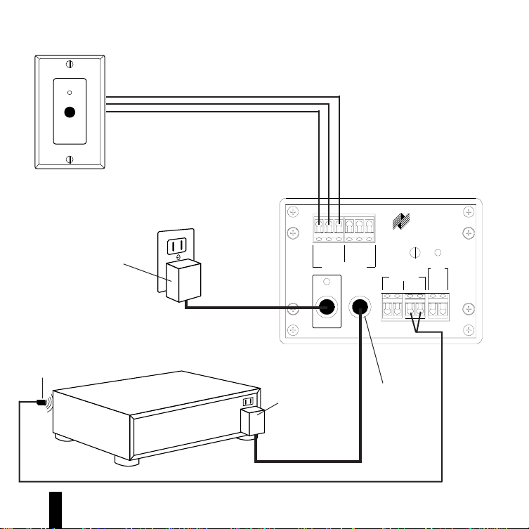
IRR4D+ IR Sensor
12V DC Power Supply
(Supplied with the IRP2+
IR Main System Unit)
Plugged into an
Unswitched AC Outlet
Powers the System
Niles IR Flasher
AA LL LL
-- MM
OO UU NN TT
WW
Power, IR Data, and Power Status Signal
via 2-conductor shielded wire
Stereo Receiver
II RR SS
EE NN SS OO RR
12V DC
Power Supply
(Not Supplied)
plugged into the
Switched Outlet
Niles Stock# XF00009
Figure 1
Connecting the IRR4D+ to a
Niles IRP2+ IR Main System
Unit broadcasting a status
feedback signal.
IRP2+ IR Main System Unit
NILES
Direct 12 volt
Status to the IR
Main System
Unit
5
Page 7

AA LL LL
-- MM
OO UU NN TT
WW
II RR SS
EE NN SS OO RR
standard 18 cu. in. (or larger) electrical box. Suitable p-rings
and electrical boxes are available from your Niles dealer or
local electrical supply company. Using the p-ring is best
because it gives you unobstructed access to the full depth
of the wall. In some instances, the use of a p-ring may be
inappropriate, such as in a retro-fit (existing) installation, or
when building codes require that wall devices be enclosed
in electrical boxes. Contact your local building code and
inspection department if unsure.
Type of Cable
The IRR4D+ connects to the Niles Infrared Systems with an
individual home run of 2-conductor shielded cable.
Recommended cables are West Penn D291, Belden 8761,
Carol C2516 or equivalent, made of two 22 gauge (or larger) conductors surrounded by a foil shield and a bare drain
(ground) wire.
DO NOT USE UNSHIELDED CABLE WITH THE IRR4D+.
When running wires inside walls, most states and municipalities in the U.S. specify that you must use a special type
of wire. Usually, the requirement is that the wire has a specific "CL" fire rating, such as "CL-2" or "CL-3". Consult your
Niles dealer, building contractor, or local building and
inspection department if unsure about which type of wire is
best for your application.
"TECH TIP"
Wire size is
expressed by it's
AWG (American
Wire Gauge)
number. The lower
the AWG number,
the larger the wire,
i.e., 20 AWG wire is
physically larger than
22 AWG.
6
Page 8

AA LL LL
-- MM
OO UU NN TT
WW
II RR SS
EE NN SS OO RR
IRR4D+ Mounting Location
Locating the IRR4D+ in the center of a room usually results
in the most even IR receiving coverage, especially if the
room is square shaped. Rooms that are L-shaped or long
and narrow require more careful consideration. With these
types of rooms, installing the IRR4D+ closest to the primary
location of the user will ensure the best performance.
Receiving Range and Pickup Angle
The receiving range of the IRR4D+ will vary according to
the IR output strength of the remote control being used.
Remote strength varies among brands depending on the
number and size of batteries used, and how many IR emitters the remote has. For example, remotes that operate on
two small AAA batteries and have only one IR emitter are
generally not as strong as remotes that use the larger AA
size batteries and have two emitters. Tests with various
manufacturers' remote controls have shown that the operating range can vary from a minimum of 18 feet to a maximum of about 30 feet.
Infrared signals travel essentially line-of-sight. They will not
pass through or around solid objects. Do not rely on an IR
signal being able to "bounce" off a wall or object to the
IRR4D+.
o
The IR pickup angle of the IRR4D+ is 60
off-axis (horizontal
and vertical) at 18 feet.
7
Page 9

WW
AA LL LL
-- MM
OO UU NN TT
II RR SS
EE NN SS OO RR
Avoiding Interference
As with any type of IR sensor, avoid locating the IRR4D+
where it will be exposed to direct sunlight. The sun emits
an enormous amount of IR energy, many times stronger
than that of a hand-held remote. Although the AGC circuitry in the IRR4D+ automatically compensates for ambient
sunlight, keep in mind that the less sunlight the IRR4D+
receives, the better the range of the remotes.
If you must install the IRR4D+ in direct sunlight, it is recommended that you use the sunlight filter. Avoid locating the
IRR4D+ near any potential sources of electrical or optical
noise, such as light dimmers, florescent lighting fixtures,
low-voltage lights, and televisions (both tube-type and projection-type).
DO NOT INSTALL THE IRR4D+ INTO ELECTRICAL BOXES
WITH 110 VOLT DEVICES.
Some states or municipalities allow devices such as the
IRR4D+ to be installed into the same electrical box as 110
volt devices, provided a "low-voltage partition" is used
between the devices. We do not recommend this. The
cable connected to the IRR4D+ can act as an "antenna" for
electrical noise. Locating the IRR4D+ cable too close to a
light dimmer or switch may interfere with the IRR4D+. If
you must locate the IRR4D+ near electrical devices, install it
in a separate metal electrical box, ground the box to the
8
Page 10

a
Figure 2 Tape or
glue the sunlight
filter (a) to the rear
of the red lens on
the snap-on insert
(b). To remove the
insert, see page 10.
WW
AA LL LL
-- MM
OO UU NN TT
II RR SS
EE NN SS OO RR
electrical system ground, and route the IRR4D+ cable several feet away from all electrical wiring.
Using the Sunlight Filter
The use of the sunlight filter will
reduce the receiving range of the
IRR4D+ to between eight and twelve
feet. The filter is installed behind the
red lens. Unsnap the Decora insert
(see page 10) and use tape or glue
to affix the filter to the rear of the
red lens see (Figure 2).
b
Avoiding Optical Feedback
If installing the IRR4D+ in the same
room as an IR flasher, it is possible
for the flasher's IR output to be
picked-up by the IRR4D+. This
effect, known as an optical feedback
loop, can cause erratic operation.
Optical feedback is similar to acoustical feedback: the howling or whistling sound heard in a P.A. system when the
microphone is too close to the speaker. To avoid optical
feedback:
1. Lower the output power of the flasher(s) using the variable flasher level control(s) on the Niles IR main system
units.
9
Page 11

WW
AA LL LL
-- MM
OO UU NN TT
II RR SS
EE NN SS OO RR
2. Re-position the flasher(s) and/or the sensor.
3. Use Niles IRC-2 flashers and cover them with the sup-
plied IR blockers.
Changing the Color of the IRR4D+
The Decora-style insert on the IRR4D+ is removable, allowing fast and easy color changes as needed. Inserts are available in a variety of colors.
If you need to change the color of the IRR4D+:
1. Obtain the IRR4D+ Decora insert in the desired color
from your Niles dealer.
2. Hold the IRR4D+ as shown in (Figure 3). Locate the two
plastic mounting tabs at the top rear of the Decora insert.
Using two fingers, simultaneously press both tabs down
(towards the center of the insert) and forward (away from
you) until the insert pops free from its mounting slots.
3. Locate the new Decora insert. Hold the IRR4D+ so that it is
facing you. Insert the two bottom tabs into the bottom slots
first, followed by the two tabs on the top. Snap the insert
into place by carefully pressing on the front of the insert.
Figure3
Removing the
®
-style Insert
Decora
"TECH TIP"
Do not exert
excessive pressure
on the plastic
mounting tabs.
10
Page 12

"TECH TIP"
Avoid installing the
IRR4D+ next to a
light dimmer.
WW
AA LL LL
-- MM
OO UU NN TT
II RR SS
EE NN SS OO RR
Installation
If you are installing the IRR4D+ into an existing wall, take
time to consider any possible obstructions which may be
hidden inside the wall, such as wood and metal studs; electrical, telephone or other types of wiring; plumbing; conduit; old wall safes; etc
1. Install the electrical box or p-ring in the usual manner.
2. Run the cable to the IRR4D+. Label the cable for future
reference.
3. Make the connections to the IRR4D+. Locate the connector on the IRR4D+ and remove it see (Figure 5). Next, strip
1/4" of insulation from the end of each wire. Tightly twist
the end of each wire until there are no frayed ends. Insert
each wire into the appropriate hole on the removable connector block; secure the wiring to the connector by tightening the small connector screws. Double-check all connections. Plug the connector back into its socket on the IRR4D+.
see (Figure 4)
.
Continued on page 13
11
Page 13

AA LL LL
-- MM
OO UU NN TT
WW
II RR SS
EE NN SS OO RR
Figure 4
IRR4D+ Parts Guide
a
b
c
d
e
g
f
e
(a) Electrical Box
(b) 2-Conductor Shielded Cable
(c) IRR-4D IR Receiver (supplied)
g
(d) Snap-on Color Insert (supplied)
(e) Device Screws (2 supplied)
(f) Decora Faceplate (supplied)
(g) Faceplate Screws (2 supplied)
12
Page 14

WW
AA LL LL
-- MM
OO UU NN TT
II RR SS
IRR4D+ Wiring Configuration
PIN 1 = Red (+12V DC)
PIN 2 = Bare (GND)*
PIN 3 = Black (DATA)
EE NN SS OO RR
123
Bare
Red Black
Figure 5
Installing the
Connector
NOTE: The color code shown above is for West Penn D291
IR cable. Actual color code of recommended cables may vary.
13
* You must use the bare drain wire for the ground connection.
Page 15

AA LL LL
-- MM
OO UU NN TT
WW
II RR SS
EE NN SS OO RR
4. Secure the IRR4D+ to the electrical box or p-ring. Insert
the 1
1/4 " long device screws into the oblong-shaped scr ew
holes on the top and bottom of the IRR4D+. Note that the
oblong shape of the screw holes allow you to position the
IRR4D+ so that it is vertical. Position the IRR4D+ so that the
screws are aligned with the threaded holes in the electrical
box or p-ring. Tighten the screws using a phillips screwdriver.
DO NOT OVER-TIGHTEN. In some instances, you may need
to loosen these screws several turns to allow the IRR4D+ to fit
flush with the Decora cover plate. See (Figure 6).
5. Use the shorter plate screws to fasten the Decora cover
plate to the IRR4D+. DO NOT OVER-TIGHTEN THE PLATE
SCREWS OR YOU MAY DAMAGE THE COVER PLATE. Line
up all the screws in the same direction for a finished look.
NOTE: Certain "old work" or "retro-fit" boxes, such as the
Carlon B225R, have a plastic "lip" which interferes with the
Decora plate screws. This lip prevents you from being able
to tighten these screws completely. To make the clearance
necessary for these screws, you must remove the parts of
the lip causing the interference. There are two ways to
accomplish this:
1. Drill through the lip of the box at the screw points.
2. Cut notches into the lip with a pair of diagonal cutters.
Figure 6
Loosening the Screws
for a Flush Fit
14
Page 16

AA LL LL
-- MM
OO UU NN TT
WW
II RR SS
EE NN SS OO RR
Operation
This manual contains instructions for the IRR4D+ only. For
specific information on the adjustment and operation of
your Niles Infrared system, please refer to the instruction
manual included with your Niles IR main system unit.
Operation of the IRR4D+ is straightforward. Simply aim your
hand-held remote at the IRR4D+. Your IR command is instantly repeated to your A/V equipment. A bicolor LED on the
IRR4D+ visually confirms remote control operation.
Troubleshooting
The bicolor LED on the front of the IRR4D+ is a useful troubleshooting aid.
The LED should light only when a remote command is
being received.
If the IRR4D+ does not work, and the LED does not light at all:
1. Test the remote control(s) by operating the A/V equipment directly. Replace the batteries if needed.
2. Double check the cable connections on all IRR4D+'s and
on the IR main system unit. Look for open, shorted or
reversed wires.
15
Page 17

AA LL LL
-- MM
OO UU NN TT
WW
II RR SS
EE NN SS OO RR
If the IRR4D+ does not work, and the LED remains
solidly lit:
1. Double check the cable connections on all IRR4D+'s and
on the IR main system unit. Look for shorted or reversed
wires.
2. Test for interference from the following sources:
●
Reduce the amount of sunlight in the area of the IRR4D+.
●
Turn off florescent, neon or halogen lights in the room.
●
Turn off light dimmers, beginning with those closest to
the IRR4D+.
Observe the IRR4D+ LED while performing all the tests. It is
possible to have interference from more than one source.
There are many methods for reducing interference. Which
solution is best for you depends on your situation. Contact
Niles Technical Support at 1-800-289-4434 if you require
further assistance.
If the LED on the IRR4D+ "flickers" dimly, and the IRR4D+
functions normally, there is no cause for concern.
16
Page 18

WW
-- MM
AA LL LL
SPECIFICATIONS
OO UU NN TT
II RR SS
EE NN SS OO RR
IR System
Compatible with virtually all brands of remotes using carrier
frequencies between 26 and 60 kHz
IR Receiving Range
Varies depending on remote strength; 18-30' typical
IR Receiving Angle
60ooff-axis (horizontal and vertical) at 18'
Mounting
In-wall, fits into most 18 cu. in. single-gang electrical boxes at least
2-3/4" deep, Decora-style face plate
Wiring Requirements
Individual home-runs of 2-conductor shielded cable, West Penn D291
or equivalent
Unit Dimensions
1-5/8" wide x 2-5/8" high
Face Plate Dimensions
Decora wall plate; 2-3/4" wide x 4-1/2" high
Depth Behind Plate
2-3/4"
17
Page 19

®
Niles Audio
Corporation
www.nilesaudio.com
12331 S.W. 130 Street
Miami, Florida 33186
Tel: (305) 238-4373
Fax: (305) 238-0185
©1999 Niles Audio Corporation All rights reserved. Because Niles constantly strives to improve the qual-
ity of its products, Niles reserves the right to change product specifications without notice. Niles, the
Niles logo and IntelliPad are registered trademarks of Niles Audio Corporation. Decora is a registered
trademark of Leviton Manufacturing Company. Printed in USA 4/96 DS00162C
 Loading...