

Page 1
INSTALLATION & OPERATION GUIDE
IRH610
IRH610
INFRARED SENSOR EXPANSION HUB
B LENDING H IGH F IDELITY AND A RCHITECTURE
®
Page 2

I
NFRAREDSENSOREXPANSION
IRH610
Infrared Sensor
Expansion Hub
TABLE OF CONTENTS
Introduction 1
Features and
Benefits 2
Installation
Considerations 2
Installation 3
Specifications 6
Contents 6
H
UB
Introduction
The IRH610 is an infrared sensor expansion hub that mounts in a structuredwiring cabinet or on a wall. It connects between the output of an infrared
sensor and a Niles main system unit.
Niles IR repeating systems are made up of three building blocks:
• IR Main System Unit—Models MSU140, MSU250, MSU480 and MSU440Z.
• IR Sensors/Keypads—Models WS100, TS100, MS100, MS200, CS100,
MVC100IR and the IntelliPad®.
• IR Flashers—Models MF1, MF1VF, MF2, MF2VF and the IRB1.
An IR repeater system with multiple sensors connected directly to the main system requires a large number of connecting wires, This creates an unsightly and
often inconvenient installation and increases the potential for connection errors.
The Niles IRH610 eliminates such problems. Simply run a single category
5 cable from the main system unit to the expansion hub, and then connect
each of the IR sensors to the distribution hub.
Page 3
I
NFRARED
S
ENSOREXPANSION
Features and Benefits
The IRH610 offers a number of improvements over
other infrared expansion hubs:
• Rustproof, weather-resistant housing of highimpact, injection-molded plastic.
• Removable connector blocks for convenient wire
connections.
• Small size and compact footprint, designed specifically to fit into a standard structured-wiring cabinet.
• Snap-in “Christmas tree” plugs (supplied) for quick
and easy installation in a structured-wiring cabinet.
• Also suitable for wall-mounting.
• Ideal for home and commercial installations.
• UL-rated to comply with all local building codes.
• 2 years parts and labor warranty.
H
UB
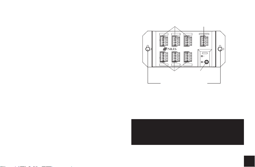
Infrared Sensor
Inputs
INPUT 1
INPUT 2 INPUT 3
IRH610
IR EXPANSION HUB
INPUT 4 INPUT 5 INPUT 6
Infrared Sensor
Inputs
Snap-in "Christmas tree" plugs
Output
to MSU
Power
input
OUTPUT TO MSU
POWER
STATUS
+12V DC
Figure 1
Installation Considerations
Type of cable
The IRH610 connects to a Niles main system unit via
a single run of category 5 cable.
When running infrared cable be sure to avoid
locating it near AC wiring. This will avoid potential
interference over long distances.
“TECH TIP”
2
Page 4

I
NFRARED
S
ENSOREXPANSION
H
UB
Mounting Location
The IRH610 is specifically designed to conveniently fit
into a structured wiring cabinet with snap-in
“Christmas Tree” plugs or it can also be wall mounted
in an unobtrusive location.
Installation
1. Run all necessary wiring to the IRH610. Label the
wires for future reference.
2. Secure the IRH610 in a suitable location.
• In a structured-wiring cabinet, use the convenient snap-in “Christmas Tree” plugs (supplied) to
mount it in the cabinet frame.
• On a wall or other flat surface, remove the snapin plugs, insert drywall screws (not supplied)
through the resulting holes, and secure the
screws to the mounting surface. TAKE CARE
NOT TO OVERTIGHTEN THE SCREWS, WHICH
COULD DAMAGE THE HOUSING.
3
3. Locate the connector plugs
(and remove them if they
are plugged in).
4. Strip 1/4" of insulation from
the end of each wire.
5. Use a small flathead screwdriver or your thumbnail to
raise the locking tabs,
exposing the holes on the
removable connector plug.
6. Insert each wire into the
appropriate hole on the
Figure 2
removable connector plug, and snap the locking
tab down.
NOTE: To help you, the connector plug is keyed.
Insert the smooth side of the connector plug into
the smooth side of the socket. Don’t force the
scalloped side of the connector plug into the
smooth side of the socket.
Page 5

I
NFRARED
S
ENSOREXPANSION
H
UB
MSU250
Main System Unit
(Cable runs over 500'
not recommended)
IRH610
Expansion Hub
Figure 3
Wiring Diagram
(Installed in an
MSU250 System)
INPUT 1
INPUT 2 INPUT 3
IRH610
IR EXPANSION HUB
INPUT 4 INPUT 5 INPUT 6
OUTPUT TO MSU
POWER
12VDC
Power supply (not supplied)
plugged into an outlet
STATUS
+12V DC
Infrared
Sensors
4
Page 6

I
NFRARED
S
7. Plug the connectors into the IRH610 as shown.
(Figure 2) The single connector plug at the upper
right is the output to the main system unit. The
other connector plugs are the inputs, each leading
from a specific infrared sensor. See (Figure 3).
For an operational overview of your infrared repeater
system refer to your main system unit manual
(MSU140, MSU250, MSU480, MSU440Z).
5
ENSOREXPANSION
H
UB
Page 7

I
NFRARED
S
ENSOREXPANSION
H
UB
Specifications
Mounting
In a structured-wiring cabinet, using convenient
snap-in “Christmas tree” plugs (supplied)
On a wall or other flat surface, secured with drywall
screws (not supplied)
Wiring Requirements
Individual home-runs of category 5 cable from each
infrared sensor and a single run of category 5 cable
to the Main System Unit.
Unit Dimensions
6.85" wide x 3" high x 1.3" deep
Contents
• IRH610 Infrared Sensor Expansion Hub X1
• Snap-in “Christmas Tree” plugs X2
• Removable connector X7
6
Page 8

Niles Audio Corporation
www.nilesaudio.com
123 31 S.W. 130 Street
Miami, Florida 33186
Tel: (305) 238-4373
Fax: (305) 238-0185
©2004 Niles Audio Corporation. All rights reserved. Niles, the Niles logo, and Blending Technology and Architecture are registered trademarks of Niles Audio Corporation. Decora is a registered trademark of Leviton Manufacturing. All other trademarks
are the property of their respective owners. Some of Niles products (or components thereof) are manufactured under one or
more U.S. Patents, foreign equivalents and/or pending patents (see product for details). Because we constantly strive to improve
our products, Niles reserves the right to change product specifications, descriptions, and prices without notice. The technical
and other specifications of information contained herein is not intended to set forth all technical and other specifications of
Niles products. Additional information can be obtained at www.nilesaudio.com or by calling Niles at 1-800-289-4434. 01/04
Printed in China DS00351ACN
 Loading...