

Page 1
IInntteelllliiPPaad
IntelliPad Ci
IntelliPad Ci
®
CCi
d
i
®
KK EE YY PP AA DD II NN SS TT AA LL LL AA TT II OO NN GG UU II DD EE
Page 2

I
NTELLIPAD
®
CIK
EYPADMODULES
INTRODUCTION .......................................................................................... 2
THE KEYPAD MODULES ............................................................................ 2
™
Solo
Master Keypad Module .................................................................. 3
™
Select
Master Keypad Module ................................................................ 3
Numeric
Transport
™
Accessory Keypad Module ........................................................ 3
™
Accessory Keypad Module ...................................................... 3
PARTS GUIDE.............................................................................................. 5
INSTALLATION CONSIDERATIONS .......................................................... 7
Where to Mount an IntelliPad Ci Keypad.................................................. 7
Choosing between Electrical Boxes or P-Rings .......................................... 7
INSTALLATION ............................................................................................ 9
Overview .................................................................................................. 9
Installing the Master Key Labels .............................................................. 10
Installing the Keypad Modules ................................................................ 13
Installing the Decora Cover Plate ............................................................ 14
OPERATION .............................................................................................. 15
SPECIFICATIONS ...................................................................................... 15
Page 3

I
NTELLIPAD
®
CIK
EYPADMODULES
INTRODUCTION
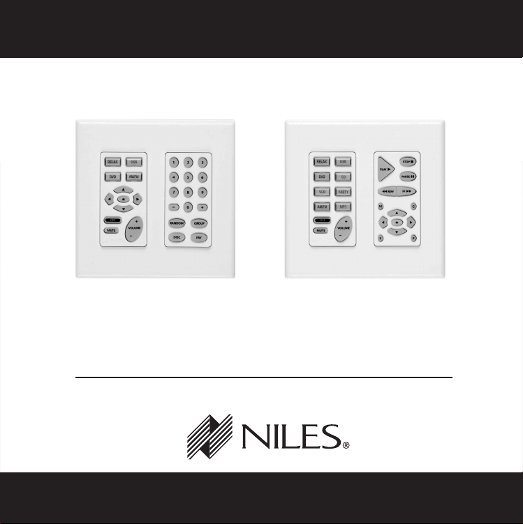
The Niles IntelliPad®Ci Keypad Modules are wall-mounted keypad controls designed for use
with Niles MultiZone Systems. There are two types of keypad modules, Master Keypad
Modules and Accessory Keypad Modules.
This Instruction Guide only covers the physical installation of the Master Keypad Modules and
the Accessory Keypad Modules. All programming, connection and operation information is
detailed in the Niles MultiZone Control System Installation and Operation Guide.
Important Note: Not all IntelliPad Ci Keypad Modules work with all Niles MultiZone Systems;
refer to the MultiZone Control Systems Installation and Operation Guide for specific keypad
compatibility.
THE KEYPAD MODULES
Either a Solo or a Select Master Keypad Module is necessary for each listening location that
requires control (See Figure 1 and Figure 2). After a zone is activated, the Transport and
Numeric Accessory Keypad Modules (see Figure 3 and Figure 4) issue the IR commands that
operate the system.
Niles MultiZone Control System
KEYPAD MODULE ZR-4630 MultiZone Receiver A4.6Ci MultiZone Preamplifier
Solo X X
Select X
Numeric XX
Transport X
2
Page 4

I
NTELLIPAD
®
CIK
EYPADMODULES
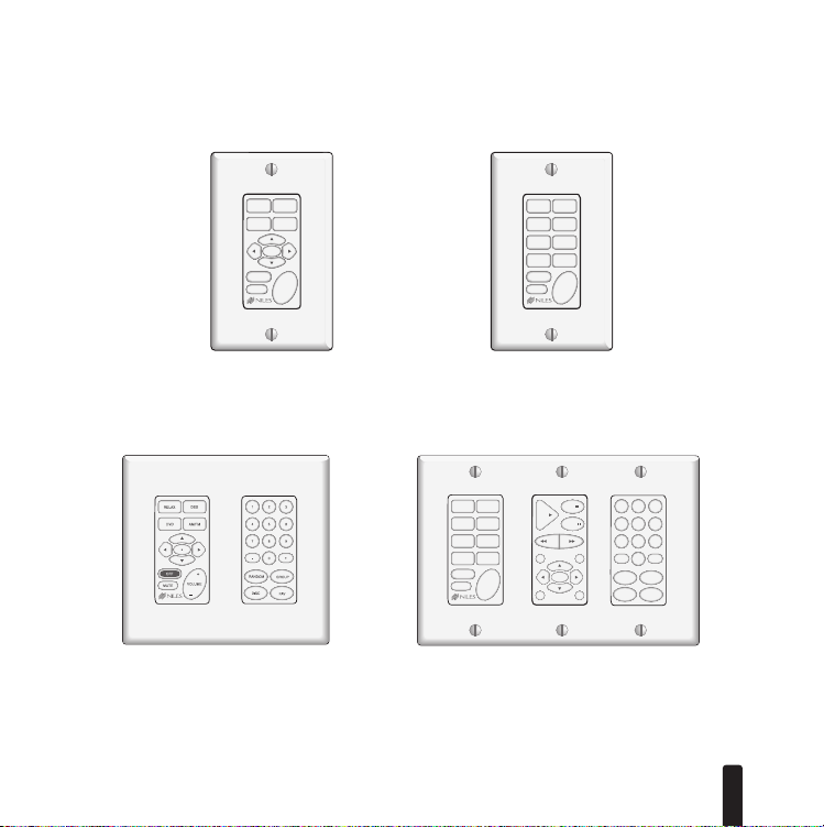
Solo Master Keypad Module
The Solo (See Figure 1) is one of two Master Keypad Modules available. It was designed to
operate alone, or in conjunction with a Numeric Accessory Keypad Module (See
Figure 3). The four Master Keys on the Solo provide the end user with customized control of
up to four audio/video components or “sources”. These Master Keys can be programmed to
initiate a sequence of customized commands.
Select Master Keypad Module
The Select (see Figure 2) is one of two Master Keypad Modules available. It was designed to
operate alone, or in conjunction with the Numeric Accessory Keypad Module, the Transport
Accessory Keypad Module or both. It provides the end-user with sophisticated control for
sources via its eight master keys.
Numeric Accessory Keypad Module
The Numeric (see Figur
e 3
and Figur
be used without a Master Keypad Module. It operates in conjunction with either the Solo or
Select Master Keypad Modules, giving the end user direct access when operating a DSS,
CD/DVD Changer, AM/FM Tuner or any other component that requires a numeric address. Its
keys change their function each time a new (Master Key) is selected.
e 4
) is one of two Accessor
y Keypad Modules. It cannot
Transport Accessory Keypad Module
The Transport (see Figure 4) is one of two Accessory Keypad Modules available. It cannot be
used without a Master Keypad Module. It operates in conjunction with the Select Master
Keypad Module, giving the end user advanced control for transport functions. Its keys change
their function each time a new source (Master Key) is selected.
3
Page 5
I
1 2
3
456
7
8 9
0
–
+
RANDOM
G
ROUP
DISC
FAV
P
E
STOP
P
AUSE
M
C
*
PLAY
R
EW
F
F
+
_
TUNER DAT
CO DSS
CO2 DSS2
VCR SAT
OFF
MUTE
VOLUME
+
_
RELAX DSS
DVD CD
VCR PARTY
AM/FM MP3
OFF
MUTE
VOLUME
DSS
AM/FM
R
ELAX
D
VD
MUTE
*
OFF
VOLUME
+
_
NTELLIPAD
®
CIK
EYPADMODULES
Solo Master Keypad Module and
Numeric Accessory Keypad Module
Figure 1
Solo Master Keypad Module
Figure 3
Figure 2
Select Master Keypad Module
Figure 4
Solo Master Keypad Module, Transport and
Numeric Accessory Keypad Modules
4
Page 6
DSS
*
I
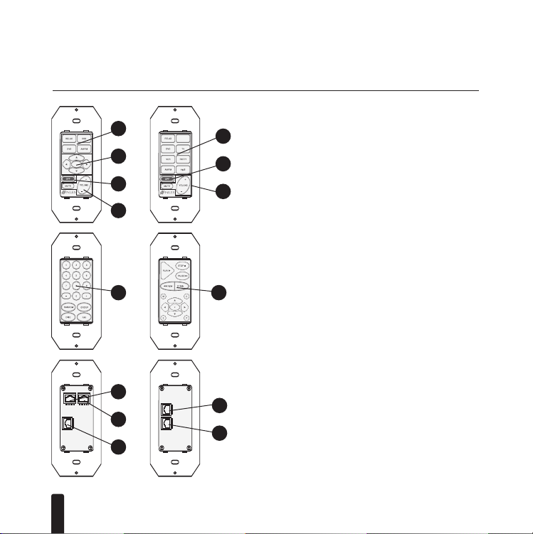
PARTS GUIDE
NTELLIPAD
®
CIK
EYPADMODULES
a
•
b
•
•
c
•
d
•
•
•
Front View: Solo/Select
a
(a) Master Keys for system automation.
(b) Function Keys for individual component control.
c
(c) OFF Key for room/zone and system OFF control.
(d) Volume and Mute Key.
d
Front View: Numeric/Transport
(a) Function Keys for individual component control.
•
a
•
a
Back View: Solo/Select and Numeric/Transport
IR Sensor: RJ-45 connector for connection of IR Sensors
(a)
(use the Niles RJ-45 to three wire adapter, for IR Sensors
wired with two-conductor shielded cable.
System: RJ-45 connector for connection to a Niles
•
•
5
a
•
b
c
•
•
(b)
d
e
MultiZone System.
Accessory Keypads: RJ-45 connector for connection to
(c)
Accessory Keypad Modules.
Input: RJ-45 connector for
(d)
connection to additional Accessory Keypad Modules.
Output: RJ-45 connector for connection to Master
(e)
Keypad Modules.
Page 7

I
NTELLIPAD
®
CIK
EYPADMODULES
INSTALLATION CONSIDERATIONS
Where to Mount an IntelliPad Ci Keypad
Convenient mounting locations for the
• Near entryways or exits
• Near a desk
• At your bedside
• Close to a telephone
• Near other wall controls
CAUTION: Do not install the
IntelliPad Ci
Some states or municipalities allow devices such as the IntelliPad Ci Keypads to be installed into
the same electrical box as 110 volts devices, provided a “low-voltage partition” is used between
the devices. We do not recommend this. Speaker wires can act as an “antenna” for electrical
noise. Locating speaker wires too close to a light switch or dimmer may cause a “popping” or
“buzzing” sound to be heard through the speakers. If you must locate the IntelliPad Ci
Keypads near electrical devices, install it in a separate metal electrical box, ground the box to
the electrical system ground, and route the speaker wires several feet away from the electrical
wiring.
IntelliPad Ci
Keypads include:
into electrical boxes with 110 volt devices.
6
Page 8

I
NTELLIPAD
®
CIK
EYPADMODULES
Choosing between Electrical Boxes or P-Rings
The mounting depth of the IntelliPad Ci Keypad Module is 2-1/2”. When installed, the unit
extends 2” behind the sheetrock wall (assuming 1/2” sheetrock). Depending on how many
Keypad Modules you are installing in a room, you can choose from a single-gang to a four-gang
standard light switch plaster ring (p-ring) or a standard 36 cubic in. (or larger) electrical box.
Suitable p-rings and electrical boxes are available from your Niles dealer or local electrical supply company. Using the p-ring is best, because it gives you unobstructed access to the full depth
of the wall. In some instances, the use of a p-ring may be inappropriate, such as in a retro-fit
(existing) installation, or when building codes require that wall devices be enclosed in electrical
boxes. Contact your local building code and inspection department if unsure.
See Figure 5.
7
Page 9

I
NTELLIPAD
®
CIK
EYPADMODULES
Figure 5
(a) Electrical box (J-box)
(b) Four pair twisted cable
(c) Solo Master Keypad Module
(d) Numeric Accessory Keypad Module
(e) Master Keys
(f) Function Keys
(g) Device screws (4 supplied)
(h) Solo Master Keypad Module
Decora style insert
(i) Numeric Accessory Keypad Module
Decora style insert
a
b
g
f
e
(j) Decora two-gang faceplate (not supplied)
(k) Faceplate screws (not supplied)
d
c
i
h
k
j
8
Page 10

I
NTELLIPAD
®
CIK
EYPADMODULES
INSTALLATION
Overview
Follow these steps to install the Keypad Modules.
1. Install a J-box or P-ring per your installation requirements (refer to Installation
Considerations for more information).
2. Run and terminate the cable from the Niles MultiZone Control System to the Keypad
location (refer to the Niles MultiZone Control System Installation and Operation Guide
for more information).
3. If installing an Intellipad Ci Silencer™Accessory Muting Volume Control, replace the
original elastomer from the Master Keypad Module with the appropriate elastomer for
the Keypad Module you are installing (included with the Silencer). Make sure the elastomer is securely in place (refer to the Intellipad Ci Silencer Installation Manual for
more information.)
4. Install the Master Key Labels (refer to Installing the Master Key Labels in this manual
for more information).
5. Make all cable connections to all Keypads and IR Sensors (refer to the Niles MultiZone
System Installation and Operation Guide for more information).
6. Secure the Keypad Modules to their J-box or P-ring (refer to Connecting the Keypad
Modules for more information).
7. Secure the Decora faceplate to the Keypad Modules (refer to Installing the Decora
Cover Plate for more information).
9
Page 11

I
NTELLIPAD
®
CIK
EYPADMODULES
Installing the Master Key Labels
Included with each Master Keypad Module is a sheet of precut and preprinted labels for
your convenience. To install the labels follow these steps:
1. Holding the Master Keypad Module as shown in Figure 6, remove the white Decora
style insert on the face of the keypad by pressing the top friction fit pegs from behind.
The insert pops free very easily with slight pressure. Pull the Decora-style insert away
from the keypad.
2. Before installing labels, determine which color (white, bone or almond) Decora style
insert is appropriate for your installation and set the labels aside in a convenient place.
3. Detach all the labels you will be using, and keep them on hand.
4. Remove all plastic key caps from the elastomer as shown in Figure 7. Place them next
to the labels.
5. If you are installing an Intellipad Ci Silencer along with a Master Keypad Module,
replace the original elastomer from the Master Keypad Module with the appropriate
elastomer for the Keypad Module you are installing as shown in Figure 8. Make sure
the elastomer is securely in place before proceeding. (Refer to the Intellipad Ci Silencer
Installation Guide for more information.)
6. Pick up one plastic key cap at a time, and drop its corresponding label inside. See
Figure 9.
7. Hold the Master Keypad Module and firmly press each plastic key cap onto its corre-
sponding Master Key, as shown in
8. Once all of the labeled caps are in place, take a look at your Master Keys. If they are in
the correct order, right side up and otherwise satisfactory, you may proceed. However,
if you need to correct one or more of the labels, remove the cap(s), adjust the label(s)
(as described in Step 4 and 6) and repeat step 7.
Figure 10.
10
Page 12

I
VO
L
U
ME
O
F
F
MU
T
E
VO
L
UM
E
M
UT
E
O
F
VO
L
U
ME
O
F
F
MU
T
E
V
O
L
U
M
E
O
F
F
M
U
TE
NTELLIPAD
®
CIK
EYPADMODULES
11
Figure 6
Removing the insert.
Figure 9
Dropping in labels.
Figure 7
Removing key caps.
Figure 10
Replacing key caps.
Figure 8
Replacing the elastomer.
Figure 11
Replacing the insert.
Page 13

I
NTELLIPAD
®
CIK
EYPADMODULES
9. To re-install the appropriate Decora style insert, hold the Keypad Module chassis so that
it is facing you as shown in Figure 11. Fit the insert around the keys of the Keypad
Module. Align the pegs on the bottom of the insert with the corresponding holes on
the steel bracket of the Keypad Module. Fix the insert into place by carefully pressing
on the front of the insert. The pegs friction-fit into the holes and hold the insert in place.
NOTE: Following all of these steps is only required for the Solo and Select Master Keypad
Modules. Numeric and Transport Accessory Keypad Modules only require that you determine
which color (white, bone or almond) Decora style insert is appropriate for your installation.
Follow Step 1 and Step 9 if you need to change the insert on an Accessory Keypad Module.
12
Page 14

I
NTELLIPAD
®
CIK
EYPADMODULES
Figure 12
1 = Green/White
2 = Green
3 = Orange/White
4 = Blue
5 = Blue/White
6 = Orange
7 = Brown/White
8 = Brown
Connecting the Keypad Modules
1. Run and terminate the four-pair twisted cable with an RJ-45 connector.
Note: The Keypad Modules require a one-to-one wiring configuration. To maintain consistency throughout all IntelliPad Ci installations, we recommend the color-coding pattern
described in Figure 12. However, you may follow the color-coding pattern of your choice,
as long as it is used consistently throughout the system.
2. Connect the terminated cable to a Master Keypad Module. Position the Master Keypad
Module as the first Keypad Module to the left when installing more than one Keypad
Module.
3. If installing Accessory Keypad Modules, connect the first Accessory Keypad Module to the
Master Keypad Module using the cable included with the Accessory Keypad Module.
See Figure 3.
4. If you have more than one Accessory Keypad Module to install, connect the second
Accessory Keypad Module to the first.
5. If using an IR Sensor, connect it to the Master Keypad Module.(see
Systems Installation and Operation Guide for instructions)
6. If installing an IntelliPad Ci Silencer, it should always be placed furthest to the right in the
J-box or P-ring, because it only has one jack. (Keypad Modules have an IN and an OUT jack.)
13
Niles MultiZone Control
Page 15

I
NTELLIPAD
®
CIK
EYPADMODULES
Securing the Keypad Modules
1. Insert the included 1–1/4” long device screws into the oblong-shaped screw holes on
the top and bottom of the Keypad Module.
NOTE: The oblong shape of the screw holes allows you to position the Keypad Module
so that it is vertical.
2. Position the Keypad Modules so that the screws are aligned with the threaded holes in
the J-box or P-ring.
3. Tighten the screws using a Phillips Screwdriver. DO NOT OVER-TIGHTEN. In some
instances, you may need to loosen these screws several turns to allow the Keypad
Module to fit flush with the Decora cover plate.
Installing the Decora Cover Plate
1. Use the shorter plate screws (included with the Decora style coverplates) to fasten the
Decora cover plate to the Keypad Module (you can choose from a single-gang up to a
four-gang plate). DO NOT OVERTIGHTEN THE PLATE SCREWS OR YOU MAY DAMAGE
THE COVER PLATE. Line up all the screws in the same direction for a finished look.
NOTE: Certain ”old work” or “retro-fit” boxes, such as the Carlon B225R, have a plas-
tic “lip” which interferes with the Decora plate screws. This lip prevents you from being
able to tighten these screws completely. T
o make the clearance necessar
screws, you must remove the parts of the lip causing the interference. There are two
ways to accomplish this:
2. Drill through the lip of the box at the screw points.
y for these
3. Cut notches into the lip with a pair of diagonal cutters.
14
Page 16

I
NTELLIPAD
®
CIK
EYPADMODULES
OPERATION
Refer to the Niles MultiZone Control System’s Manual for information on how to operate
the Keypad Modules once installed.
15
Page 17

I
NTELLIPAD
®
CIK
EYPADMODULES
SPECIFICATIONS
WIRING REQUIREMENTS
Keypad to Niles MultiZone Control System
Up to 500 feet of individually home-run four pair twisted cable (CAT3 or CAT5)
IR Sensor to Master Keypad
Up to 500 feet of individually home-run four pair twisted cable (CAT3 or CAT 5). Or, up to
500 feet of individually home-run 22 gauge two-conductor, shielded cable (West Penn D291
or equivalent).
NOTE: A Niles Adapter (FG00852) is required to connect an IR Sensor when using two
conductor shielded cable.
FCC CERTIFICATION
Class “B” certified for use in residential environments.
MOUNTING
In-wall mounting Decora-style modules, fit into electrical boxes at least 2-1-2" deep.
UNIT DIMENSIONS
Model Height Width Depth
Solo 4" 1-3/4" 1-5/8"
Select 4" 1-3/4"
Numeric 4" 1-3/4" 1-1/8"
Transport 4" 1-3/4" 1-1/8"
1-5/8”
16
Page 18

Niles Audio Corporation
www.nilesaudio.com
12331 S.W. 130 Street
Miami, Florida 33186
Tel: (305) 238-4373
Fax: (305) 238-0185
egistered trade-
©2006 Niles Audio Corporation. All rights r
marks of Niles Audio Corporation. Decora is a registered trademark of Leviton Manufacturing Company. All
other trademarks are the property of their respective owners. 1/06 DS00266CCN
eserved. Niles, the Niles logo and IntelliPad ar
e r
 Loading...