

Page 1

Niles Audio Corporation
IntelliControl
IntelliControl
IntelliControlIntelliControl
V ersion 8.0 July 2000
Reference Manual
Reference Manual
Reference Manual Reference Manual
Page 2

Contents
1A. IntelliControl Features and Benefits...................................................................................................................1
A Complete System......................................................................................................................................................1
One Touch “Intelligent Macros” To Turn The Entir e Home Theater On or Off.................................................... 2
Automatically Unmute the System..............................................................................................................................2
Manage and Automate “Unf riendly” Compone nts..................................................................................................2
Trigger Screens, Screen Masking Devices, Projector Lifts, Curtains and Drapes..................................................2
PC Programmable with IntelliFile II......................................................................................................................... 2
Proudly Made in USA................................................................................................................................................. 3
1B. IntelliControl Parts Guide.....................................................................................................................................3
The Tabletop Remote.................................................................................................................................................. 3
The Main System Unit (MSU).................................................................................................................................... 4
1C. Selling the System...................................................................................................................................................6
Selling Automated Home Theater Systems................................................................................................................6
Solving The Problems of Co nventional Home T heater Oper atio n...........................................................................6
Problem One: Turning the System On..................................................................................................................6
The IntelliControl Solution: Syncron ization (Syn c)............................................................................................. 6
Problem Two: Selecting Inputs & Modes............................................................................................................. 8
The IntelliControl Solution: Softw are Managers to Select Inpu ts and Modes....................................................8
1D. Comparison of Home Theater Control Sys tem s..............................................................................................10
2A. Power Syncronization..........................................................................................................................................11
Infrared Turn On/Off Requires “Sync”...................................................................................................................11
Components that Don’t Need Sync – Thos e with L atchi ng Pow er.........................................................................11
Remember the Exception – Tuners built into Receivers and Televisions...............................................................12
2B. Sync Methods and Options.................................................................................................................................12
Video Sync.................................................................................................................................................................12
Syncing the TV.....................................................................................................................................................13
12 Volt Sync...............................................................................................................................................................13
1. 12V DC Sync via a Wall Adapter Plugged into a Switched AC Outlet...................................................... 13
2. Niles LS-1 Light Sensor................................................................................................................................14
3. Niles OTI-512 Voltag e Sens or.......................................................................................................................14
4. Niles APC-2 Current Sensin g Switcher........................................................................................................14
5. Niles IPC-6 Current Sens ing AC Pow er Controller.....................................................................................14
Each Sync Connection on the M ain Sys tem U nit C orres ponds to a Par ticul ar Mas ter K ey on th e Tablet op
Remote.......................................................................................................................................................................15
Conventional Labeling Rule: Video on the Left, Ev erything Els e on the Right.....................................................15
Once Again: Remember the Exception............................................................................................................... 16
i
Page 3

2C. Component Compatibility..................................................................................................................................16
Infrared Compatibility..............................................................................................................................................16
Testing Components for Automation Conflicts........................................................................................................17
Testing Components for Sync Method.....................................................................................................................17
Sync Off Delay.....................................................................................................................................................18
3A. Pages, Keys, and Sequences................................................................................................................................21
An Address For Every IR Comman d........................................................................................................................22
Issue A Sequence From A Functio n Key..................................................................................................................22
Purpose of the Master Key Pages............................................................................................................................23
Purpose of the Default Page.....................................................................................................................................23
Purpose of the Library Pages...................................................................................................................................24
3B. Function Key Memory Limitations...................................................................................................................24
3C. Master Key Automation: Par t 1 - One Touch Sys tem Turn On...................................................................25
Sync Snapshot............................................................................................................................................................26
Event One – Initial Sequence....................................................................................................................................26
Event Two - TV Power..............................................................................................................................................27
Event Three - Preamp Power...................................................................................................................................27
Event Four - Component Power (N ot Applicable to Mas ter Keys Nine a nd Ten).................................................27
Event Five - TV Input................................................................................................................................................27
Event Six - Preamp Input..........................................................................................................................................27
Event Seven - Surround Mode..................................................................................................................................27
Event Eight - Ending Sequence................................................................................................................................27
3E. Master Keys: Part 2 - Special Features............................................................................................................28
Automation Bypass for Manually Adjus ted Featur es..............................................................................................28
Automation Bypass for a Typical A pplication....................................................................................................28
How to Program “Component P ower” for Multiple Master Keys w hich Share a Common Source..................29
Press and Hold a Master K ey...................................................................................................................................30
Custom Programming for Preamp/Receiver s with Sep arate On/Off C ommands.................................................30
3F. Master Keys: Part 3 - Direct IR, Sequence IR, and Managers......................................................................31
Direct IR - A Different “Single” IR Code for each of the Compon ent’s Inpu ts.....................................................31
Testing Direct IR ..................................................................................................................................................31
Sequence IR— a Single “I nput Toggle” Comman d and a Se cr et Back-Door “An chor” C ommand( s)..............31
Finding the Secret Back-Door “An chor” Command..........................................................................................31
Testing the “Anchor” Command.........................................................................................................................31
Input Manager – For Components with only a Sin gle “Input Toggle” C ommand...............................................32
ii
Page 4

Testing the “Input Manager” Method..................................................................................................................32
Determine the “Defaults”.....................................................................................................................................32
3G. Master Keys: Part 4 – Intelligent System Tu rn Off........................................................................................32
Event 1 - “System Off” Initial Sequence..................................................................................................................32
Event 2 - TV Auto Turn Off.......................................................................................................................................33
Event 3 - Auto Volume Reset....................................................................................................................................33
Event 4 - Preamp Auto Turn Off..............................................................................................................................33
Event 5 - Component Auto Turn Off........................................................................................................................33
Event 6 - “System Off” Ending Sequence................................................................................................................33
3H. The Audio, Video, and Assignable Relays with Control Vol tage Output....................................................33
Relay Voltage Limitations.........................................................................................................................................33
Audio 12V Output.....................................................................................................................................................34
Video 12V Output and Relay....................................................................................................................................34
Assignable 12V Output a nd Rel ay............................................................................................................................34
3I. Utilities.....................................................................................................................................................................34
ID Code .....................................................................................................................................................................34
Volume Reset.............................................................................................................................................................35
IR Routing..................................................................................................................................................................35
Dual TV .....................................................................................................................................................................35
Mute Manager...........................................................................................................................................................36
Memory Usage..........................................................................................................................................................36
4A. Using Your Original Remote Controls via an I R Repeater Sys tem.............................................................37
Integrating a Second Zone........................................................................................................................................37
Turning On Common Sources in Multi-Zone Systems............................................................................................38
Integrating the Niles RVL-6 an d MRZ-6 Multi-Ro om Controllers.........................................................................39
Multiple TV Array In A Media Room.......................................................................................................................39
Integrating the Niles IntelliPad™ Into the H ome Theater......................................................................................39
Integrating a Learning Touchscreen Int o An IntelliCo ntrol Home Theater..........................................................39
Teach the RF/IR Conversion Codes for the Mas ter K eys, Functi on Keys, and Sys tem Off Key...........................40
Step-by-Step Installation of a New System..............................................................................................................41
1. Connect, Power Up, and Test The Home T heater..........................................................................................41
2. Check MSU Location for Freedom from Interfer ence....................................................................................41
3. Connect and Power Up the MSU, Your PC, an d the I ntelliFile II..................................................................41
5. Testing and Troubl eshoot ing RF Trans miss ion and Rec eption.......................................................................42
iii
Page 5

6. Connect Flashers a nd Sync Cables...................................................................................................................43
7. Flasher Level Check..........................................................................................................................................44
8. The IR/RF Test LED.........................................................................................................................................45
Specifications................................................................................................................................................................46
The IntelliControl Tabletop Remote.........................................................................................................................46
The IntelliControl Main System Unit.......................................................................................................................46
iv
Page 6

Chapter
IntelliControl® Home Theater Automation
System
1A. IntelliControl F eatures and Benefits
Introducing the IntelliContr ol, the wor ld’s f ir st affordable home theater automation s ystem
expressly designed to provide true one-touch operation. Unlike universal remote controls,
the IntelliControl System senses the actual on/off state of all of your audio/video
components. When you press a Master Key, the built-in microprocessor has the
intelligence to decide which components need to be powered up , depending on what
Master Key was selected and the On/Off state of the components.
After the system components have been turned on, the IntelliControl issues all of the
necessary surround-sound mode commands, the preamp input selection commands, the
TV input commands, and any “play” or “f avorite station” commands. For the first tim e,
most anyone in the famil y can operate the system without trai ning, prompting or headscratching.
Ten Master Keys can be custom labeled to reflect your system components or features.
When you select a source, it lights up letting you know it’s ready to be controlled.
Traditional universal remotes are confusing because “aux” might actually select the
satellite receiver, and “VCR2” s elects the TV. Now, each of the sour ces in your system
are correctly labeled. By pressing one of these Master “scene-setting” Keys, your system
is completely turned on, configured, and set up to watch and control the selected source.
The only other system s capable of this unique combination of custom labelin g and full
automation of a mixture of multi-brand components are very expensive touchscreen
automation systems. In addition to the expense, touchscreens are menu-driven, and
always require more than one step to operate. The IntelliControl offers genuine onetouch operation at an affordable price.
A Complete System
The system consists of an ergonomically designed RF (radio frequency) Tabletop Remote
Control and an “intelligent” Main System Unit (MSU). Powerful combinations of hardware
and software functions within the Main System Unit manage and control every aspect of
the home theater.
1
Page 7

One Touch “Intelligent Macros” To Turn The Entire Home Theater On or Off
Normal home theater system operation requires you to turn on multiple com ponents. It is
easy to make a mistake, whic h can cr eate a situati on wher e you m ust be a detec tive and
hunt down the fugitive component that is “off”, when it really should be “on”. The
IntelliControl eliminates al l of this tr oub les hoot ing. A s ingle touch of any of the ten ins tal ler
labeled “scene-setting” keys (typically label ed for sources e.g. T V, VCR, CD) will initiate
an intelligent sequence of commands (macro).
The IntelliControl will only issue a component’s power command if it is off. All of the
necessary components are turned on, every time. After the system components have
been turned on, the IntelliControl automatically completes the system configuration,
enabling you to watch and listen to the selected source. No w, a complex mix of different
brands of audio/video components can be operated with the same ease and simplicity of a
traditional television set.
Automatically Unmute the System
Many surround-sound preamps or receivers can unpleasantly surprise you with their
“mute” functions. For example, if you mute the system to answer a phone call and then
press a Master Key or the “Volume Up” Key, the volume will be too low. If you first raise
the volume then remember that you muted it, a press of the “Mute” button will issue a
deafening blast.
The IntelliControl is capable of “managing” the mute command. The system will mute
when you press the “Mute” key. However, it will now unmute automatically whenever you
press a Master Key, “Volume Up” or the “Mute” key.
Manage and Automate “Unfriendly” Components
Many high-performance audio/vid eo components have remote control functions that are
impossible to automate with conventional automation equipment. The components are
really just designed for the user who demands manual control at all times. The
IntelliControl has unique software “managers” which enable complete automation of
components that are difficult to automate. For the first time, components chosen for
optimum performance can be automated using the IntelliControl.
Trigger Screens, Screen Masking Devices, Projector Lifts, Curtains and Drapes
The IntelliControl provides dedicated 12-volt DC triggers for both the Video and the Audio
Scenes. The Video scene also triggers a latching (normally open) and a latching (normally
closed) contact rela y. An "assignable" re lay and 12v DC vo ltage can be tr iggered b y any
key as a step in a programmed sequence. These relays and voltages enable devices
which are not IR controlled to be automated by the IntelliControl system.
PC Programma ble with Inte lliFile II
An IntelliControl system conf iguration can be programmed, saved, and edite d using the
Niles IntelliFile II PC Interf ace and Program ming Software. A PC run ning W indows 95 or
98 is required. Unfortunately, Niles does not offer a Mac compatible version at this time.
2
Page 8
Proudly Made in USA
The IntelliControl is designed and built in the USA and comes with a limited two year parts
and labor warranty.
1B. IntelliControl Parts Guide
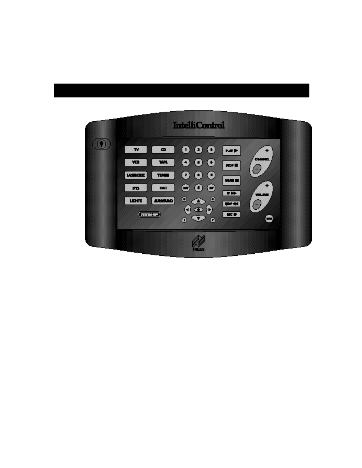
Figure 1 The IntelliControl Tabletop Remote
The Tabletop Remote
The Tabletop Remote is a radio f requency (RF) tr ansm itter which comm unicates with the
Main System Unit (MSU) on a RF carrier frequenc y of 418MHz. The T abletop Remote
features the following:
• Ten Master Keys – The ten Master Keys on the left side of the remote may be
custom labeled and will initiate the IntelliControl’s automation functions when
programmed via the Intell iFile II PC Interf ace and Program m ing Sof tware. Press ing a
Master Key will prompt the MSU to check the On/Off status of all of the components in
the system and issue the necessary IR commands to conf igure the system so the
user may enjoy the selected source.
• System Off Key – When pressed, the Tabletop Remote will instruct the MSU to
check the On/Off status of all the components in the s ystem and issue the n eces sar y
IR commands to power down the system.
3
Page 9
• Backlight Key – Pressing the Bac klight Key (located on the upper left corner of the
Tabletop Remote) will illuminate all the keys to enable com plete c ontrol of the system
in dark rooms.
• Function Keys – The thirty-two Function Ke ys inclu de the num er ic, m enu, tr ansport,
mute, volume, and channe l keys. Once a M aster Key is s elected, the Function Keys
correspond to the functions of that selected source. However, the volume and mute
keys are usually programmed to control the preamp only.
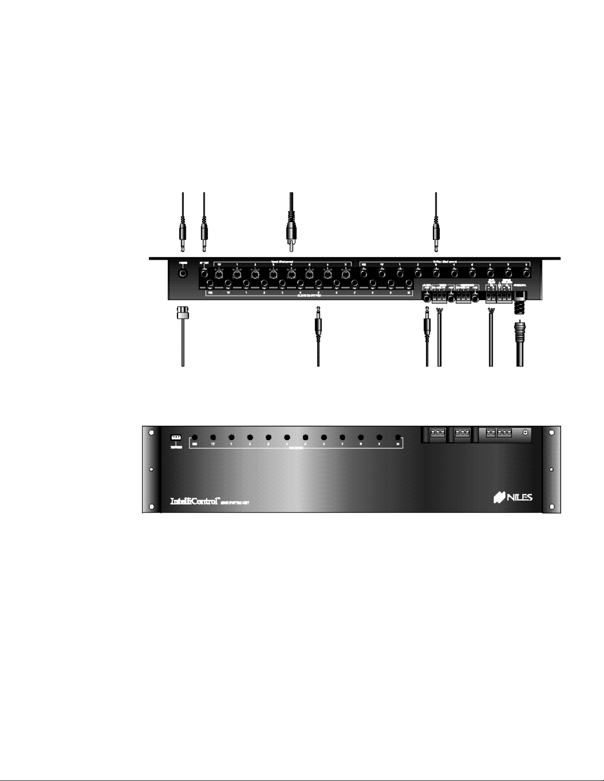
Figure 2 Main System Unit – Top View
Figure 3 Main System Unit – Front View
The Main System Unit (MSU)
The Main System Unit is the “brain” of the Intel liControl s ystem. Once a RF command is
issued from the Tabletop Remote, the MSU processes the command and controls all
functions of the system. All programming is stored inside the MSU. The Main System Unit
features the following:
• Power Connector – Located on the upper left side of the MSU, the Power Connector
accommodates a 12V DC 800mA UL approv ed external power supply (FG00667 included).
4
Page 10

• RF Test Port – Also locat ed on the upper left side of the MSU is the RF Tes t Port.
The RF Test Port enables you to rec eive real-time confirmation that RF s ignals are
received and understood, detect interference, and test for sync status. The bicolor
RF/IR Test LED (FG00727) is available as an accessory, and should be sold and
installed in every IntelliControl home theater.
• Video Sync Inputs – The eight Composite (RCA) Video Syn c Port s are provi ded to
sense the on/off power status of IR controlled components with v ideo output. Your
system design may require additional video cables and “Y” adapters.
• 12V Sync Inputs – The 12V Sync Inputs are provided to sense the on/off power
status of IR controlled com ponents. Your system design may require 12V DC wall
adapters or Niles switchers (APC-2, LS-1, OTI-512) with a 10’ Accessory Cable
(FG00724).
• Transfer Connector – T he three conductor T ransfer Connector enables the transf er
of programming information from the IntelliFile II PC Interface or the original
IntelliControl Programm er to the MSU and vice versa. You may want to perm anently
install a 20’ Transfer Cable (FG00725) to provide future access for programming
updates.
• IR Flasher Outputs- T he twelve IR Flasher Outputs iss ue IR codes to IR controlled
components. Your system design may require IRC-2P MiniFlashers (FG00726)
and/or 3.5 to 3.5 mono mini-plug cables for hardwired connections to compatible
components.
• 12V DC Control Voltage Outputs – These connections can be used to trigger
screens, Niles switchers, and other devices. Your system design may require 10’
Accessory Cables (FG00724). The IntelliControl features an “Audio 12V” output
(active whenever a sour ce that utili zes the pream p is selec ted), a “Video 12 V” output
(active whenever a sour ce that utilizes the T V is selected), and a n “Assignable 12V”
output (activated as part of a sequence with the “Assignable Relay On” command).
• Dry Contact Closures / Relays – These connections can be used to trigger lights,
curtains, screens, lifts, and other devices. Your system design may require multiconductor cable. The IntelliControl features a “Video Relay” (active whenever a
source that utilizes the TV is selected), and an “Assignable Relay” (activated as part of
a sequence with the “Assignable Relay On” command).
• IR Data Input Connectors (“Home Theater IR” and “Second Zone IR”) – These
connections enable IR data to be fed into the MSU from Niles IR sensors, keypads, IR
Main System Units, or Multi- room Controllers around t he house. IR data received at
the “Home Theater IR” port is pas sed through all flashers. IR data received at the
“Second Zone IR” port is passed through flashers 1 – 8 only.
• Antenna Socket – This F-connector accommodates a 1’ to 200’ length of high quality
quad-shielded RG-6 coax cable with 6-3/4” of the center conductor exposed. It is
suggested that the exposed tip of the antenna be located as far from the main
equipment location (and as close to the user’s location) as practical.
• IR Flasher Level Controls – The twelve flasher lev el controls enab le the install er to
control the strength of the IR output sent to each of the components in the system.
Flasher strength increases as the pots are turned clockwise (a jeweler’s screwdriver is
5
Page 11

required). Before beginnin g to pro gr am the system, it is recommended that a Niles IR
Sensor be connected to the MSU’s “Home Theater IR” port and each of the flasher
level adjustments be set using the components’ original remote controls.
1C. Selling the System
Selling Automated Home Theater Systems
In the past, selling a hom e theater system has always in volved system design trade-off s.
With every profitable upgrade you sell to your cust omer there is a “hidden” cost to you
after the installation, which is your time.
Along with selling and installing the system, you must assume the responsibility for training
the customer to actually use the n ew features or enjoy the enhanc ed performance. T he
frustration many consumers feel, even after repeated training sessions, certainly limits
referrals and sometimes leads to refunds. In any event, the time required to drill customers
so that they can reliably turn on and operate the s ystem c an be ridicu lousl y expensive f or
you and tedious for your customer. The IntelliControl enables you, the salesperson, to
design and sell absolutely automated home theater systems (systems that require minimal
training to operate and which generate repeated referrals).
In order to successfully sell the IntelliControl to consumers, you should be able to
effectively present what “Home Theater Automation” means, in terms the consumer will
understand. The following sections elaborate how the IntelliControl’s autom ation differs
from anything that has ever been sold and installed into a home theater at this price point.
Solving The Problems of Conventional Home The ater Operation
The IntelliControl uses a unique approac h to solve the classic problems of operating a
home theater. In this sectio n, we will take a closer look at what those probl ems are, and
how the IntelliControl solves them.
Problem One: Turning the System On
In a conventional system, turning on a home theater with a remote control can be so
difficult, that most people simply walk up to the equipment where they can see each
component and try to remember what needs to be d one. Since m os t com ponents f eature
“toggle” power commands (one button which turns th e component both “On” and “Off ”),
you cannot simply press the power button on each of your remotes in turn or issue a
macro of many power commands from a sequencing remote or touchscreen. For
example: If you put the videotape into your VCR, it would autom atically turn on, and the
act of pressing the power button on each of your remotes (or pressing the macro button on
your touchscreen) would turn on the rest of your system, but would turn off the VCR).
The IntelliControl Solution: Syncronization (Sync)
The IntelliControl’s Main System Unit is connected to al l of the h ome theater components.
Its unique video and 12V sensing circuits enable it to actually “know” whether each
component is on or off.
6
Page 12
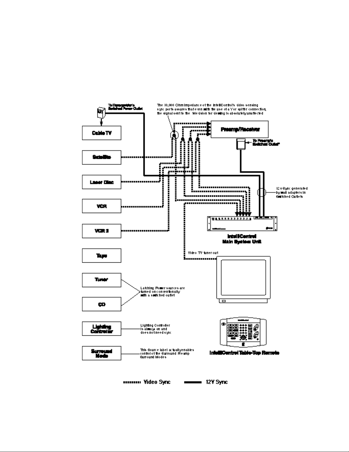
When the user presses any Master Key, the Inte lliControl’s microprocessor checks the
power status of each com ponent and synchronizes the s ystem to the end user ’s desires
by issuing only the necessary power comm ands. No matter what their pre vious on or off
states, the IntelliControl will know exactly which components need to be powered up.
Power synchronization is not just used when the system is first turned on. It is also used
when a new Master Key is selecte d. The IntelliCo ntrol check s to s ee if anything ne eds to
be turned on or off, and issues the necessary power commands.
Figure 4 System Schematic
7
Page 13

Problem Two: Selecting Inputs & Modes
Home theaters need to have the s urround receiver’s audio inputs selecte d, the correct
surround-sound mode selected, and the correct TV input selected. Even if there is a
separate button for every mode or input, the user m ust remember which input label is
correct for each component and keep track of which remote is which. Although some
remotes have the ability to issue “macros”, most systems incorporate at least one
component that is “macro-proof” (a component that uses a single “INPUT” or “MODE”
command to cycle through all of the choices). T here is no way for the rem ote control to
“know” which input was last selected. So, the consumer must remember which input it was
and cycle through the choices manually. Operation is frustratingly complex for anyone.
The IntelliControl Solution: Software Managers to Select Inputs and Modes
The IntelliControl’s Ma in System Unit is program med with powerf ul software “m anagers”
that automate Input and Mode s election. No m atter what t ype of IR comm and is requir ed
to change the inputs or the modes, The IntelliControl automatically selects the correct
configuration for the source selected.
Additionally, for the first time, you can design sophisticated configurations that improve
system performance without worrying about the difficulty the end-user might have
remembering everything (i.e. you could run S-Video direct to the TV’s S-Video input for the
DSS, while composite video is run from the other sources to the TV’s video input).
This automation does not get in the wa y of hobbyists who lik e to play with the surr oundsound modes. The IntelliControl will automatically select the normal surround-sound
mode for each input when the user presses a Master Key.
However, if the hobbyist decid es to experiment with different m odes, he/she can press
one of the ten custom labeled M ast er Keys (labeled “Surround” for exam ple) , change a nd
adjust the surround-sound, and when they return to the last source selected, the surroundsound mode will not automatically change back to the norm al m ode ( this is an example of
the IntelliControl’s “Automation Bypass” feature). Only when the user selects a new source
will the IntelliControl take over again and autom atically select the def ault surround-sound
mode for the new source. Now, the hobbyist can peac efully coexist with the rest of the
family, because he/she will ne ver accidenta lly leave the s ystem in the wrong input or the
wrong surround-sound mode.
Problem Three: Decorating El ectronically – Putting All The Components In
Plain Sight
If the equipment is placed out of sight behind cabinet doors and an infrared repeater
system is installed, the user cannot see which com ponent is on, which input is selected,
etc. Either way, the user is cursed with either a stack of components with cryptically
flickering LEDs in plain sig ht or a cabinet full of components that can onl y be operated if
the doors are open.
The IntelliControl Solution: Automation Allows Behind Closed Door
Operation
Because the IntelliContro l automates all of the system’s functions , the user doesn’t need
to check the power status or the currently selected input of each component. The
IntelliControl is constantly checking the power status and the software Managers are
8
Page 14

correctly configuring the system for any source. As a result, the components can be
placed behind closed doors.
Problem Four: When The System Turns On, The Volume Is Too Low, or Too
High
Surround-sound pream ps/receivers typically stay at the last volume selected when they
are turned off. As a result, tur ni ng on a system can sometimes be puzzlin g bec aus e th ere
is no sound, while at other times, turning on a system can be ear-shattering.
IntelliControl Solution : The Volume Re sets Automatica lly At Turn Off
The IntelliControl can be programmed to automatically reset the rece iver’s volume to a
comfortable level. When the “System Off” key is pressed, the IntelliControl can be
programmed to issue the “Volume Down” for as long as necessary to take the
preamp/receiver to minimum, then raise it to a comfortable level regardless of how loud or
soft the system had been playing. Only then do es the IntelliControl turn the system off.
The system always turns on at a moderate volume setting. No more puzzling or surprising
accidents.
Problem Five: The Pitfalls of Mute
It has been traditional for most surround-sound receivers and pream ps to offer the end
user a separate “Mute” button. This button has created thousands of service calls
worldwide. You press “Mute” once, the system mutes, you press it again and it unmutes.
However, the user must remember that the system is muted. If the user forgets, then there
is no sound. Or worse, a service call is created.
IntelliControl Solution: Software Managers to Manage Mute
The IntelliControl’s Main System Unit can be programmed to automate the “Mute”
command. Now, when one person presses “Mute”, nobody has to r emember anything.
The IntelliControl remembers. When anyone touches any key, the preamp will unmute.
Problem Six: Infrared Remote Controls Are Line-Of-Sight Only
In a conventional system using a “macro” remote, various problems can occur if the
remote control is not poi nted correctly, or not held s teadily in one position until all of its
commands are issued. If the user’s hand slips, or someone walks by, some of the
commands may not be received. Annoying problems, which are exaggerated in larger
rooms, will occu r.
IntelliControl Soluti on: Radio Frequency Comman ds Between th e Tabletop
Remote Control and the System
The IntelliControl issues a single RF “automation” command when a button is pushed.
Because radio signals operate at any angle and cannot be physically blocked, the
system’s automation is extremely reliable. All macros are issued by the MSU, which feeds
IR commands directly to the com ponents. The IntelliControl provides the end-user with
one-touch operation every time.
9
Page 15
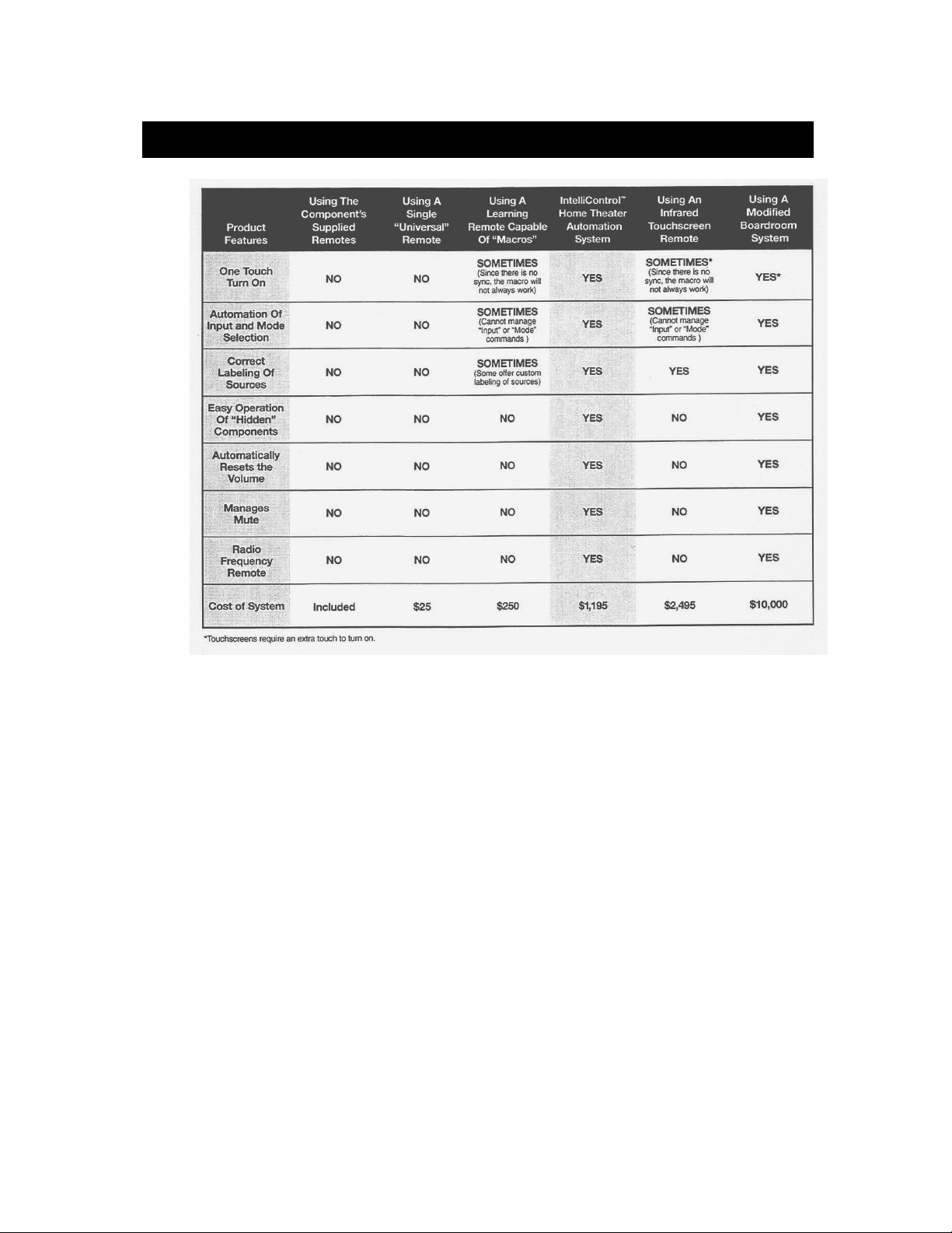
1D. Compariso n of Home Theater Control Systems
Figure 8 System Comparison
10
Page 16
Chapter
Po wer Syncronization and Component
Compatibility
2A. Po wer Syncroni zati on
Infrared Turn On/Off Requires “Sync”
Every component which requires an infrared command to turn “On” or “Off” must be
synced to the IntelliControl. Based on the “sync status” of the selected component, the
IntelliControl will know whether or not to issue a “Power” or “On” command when a Master
Key is selected. The same basic procedure applies to turning the system off. The
IntelliControl monitors the on/off status of the components in either of two ways, “12V
Sync” and “Video Sync”.
Components that Don’t Need Sync – Those with Latching Power
Components which “latch” into an “ On” state when power is supplied do not need sync.
The term “Latching Power” describes any component which has a Po wer button which
“latches” into the “On” position and can be turned on automatically when AC power is
supplied. “Single” and “5-disc” CD players, as well as most Tape Decks traditionally plug
into the switched outlet of the preamp/receiver an d do not requir e IR “power” or “On” and
“Off” commands to manage their power. Check the power consumption of each devices in
the system and total them. If all of the connected component’s combined power
consumption exceeds the limitations of the pream p’s switched out let, you must specify a
Niles AC-6+ to switch the “On” and “Off”. See Figure 9
Figure 6 Using the Niles AC-3 (or AC-6+) to switch on source components featuring
“latching” power via the Audio Control Voltage Output. (The Audio 12V is automatically
activated whenever a source that utilizes the preamp is selected).
11
Page 17

For some components, it may be useful to turn them on and off with a Niles AC-6+
triggered by one of the three r elay voltages (“ Audio”, Video”, or “Assignab le”). You cou ld
elect to turn on and off a latching power CD player via the Assignable Relay if you
specified an AC-6+ to po wer it on and of f. W hen programm ing, you could add t he “Relay
On” command to the CD Master Key’s Ending Sequence and the “Relay Off” command to
all other Master Keys and the “System Off” Key.
Figure 7 A projector with latching power may be turned on via an AC-6+ triggered by the
Video Control Voltage Output. (The Video 12V Output is automatically activated
whenever a source that utilizes the TV is selected).
Remember the Exception – Tune rs built into Receivers and Te levisions
It is important to note that a stereo receiver has both a tuner and a preamp in one chassis.
If the receiver does not f eature separate “On” and “Off” comm ands (or latc hing power, in
which case it could be activated via the “A udio 12V” trigger and an A C-6+ as described
above), it must be synced to the “Preamp 12V” sync port.
Since the receiver’s AM/FM tuner is automatically turned on/off with the receiver, the tuner
itself does not need sync (or to have a “Component Power” command programmed on the
tuner’s page under “Com ponents” when programming with IntelliFile II) . Essentially, the
tuner is treated as a component with latc h ing p o wer. Likewise, most televisions have both
a television tuner and a telev ision m onitor in one chas sis. You s ync t he televis ion m onitor
to the TV’s dedicated sync port, and treat the television tuner as a s ource with latching
power.
2B. Sync Methods and Opti ons
The following are the m ethods you will use to s igna l the Intel liContr ol that a com ponent is
on or off.
Video Sync
Most video sources provide either a picture or a blue-sc r een when t he de v ice is on. Usi ng
a Y-splitter, this video output can be routed to both th e video switching Preamp ( or TV)
12
Page 18

and to the MSU’s composite vid eo sync port which corres ponds to that source’s Master
Key.
Note: The labeling of the Master Keys on the Tabletop Remote must match the sync
connections on the MSU. (For example, if the VCR is Master Key #4, one side of the
VCR’s split video output must be connected to video sync port #4).
The IntelliControl’s video s ync ports have an input im pedance of 10,000 ohm s. This high
impedance circuit assures that even with the use of a “Y” or splitter connec tion, the s ignal
sent to the television (or Pr eamp) is absolutel y unaffec ted. Typical ly, a “ Y” connec tor and
an additional video cable are nee ded for video sync. If the com ponent has more than one
video output, only a cable is needed.
Syncing the TV
Televisions which have m ultiple in puts present a sync probl em. Som e TV’s do not outp ut
a video signal from the Monitor Video output when there is no signal coming into the
selected input. Thus, the IntelliControl will be deceived into thinking that the TV is off, when
it is on. Although a TV’s monitor output will not provide reliable sync, there are four
options:
1. Use the TV’s “Tuner Output” if available. This will ensure that the Sync is reliable.
2. Specify a Niles APC-2 current sensing device to detect the flow of current to the TV
when it is on. Note: This is the only reliable way to sync a Plasma TV (assuming it
does not feature separate “On” and “Off” codes).
3. Use a Niles LS-1 Light Sensor. (See “12V Sync” options below)
4. Use a TV with separate “On” and “Off” commands.
Note: The TV’s sync signal output (video or 12V) must be connected to the dedicated “TV
Sync” port on the IntelliControl MSU.
12 Volt Sync
The IntelliControl Main System Unit has 12V Sync connections for the system’s
preamp/receiver, T V Monitor (or projec tor), and up to ei ght sourc e com ponents. T he 12V
Sync signal lets the Intelli Control know whether the component is on or off and can be
supplied by five different methods:
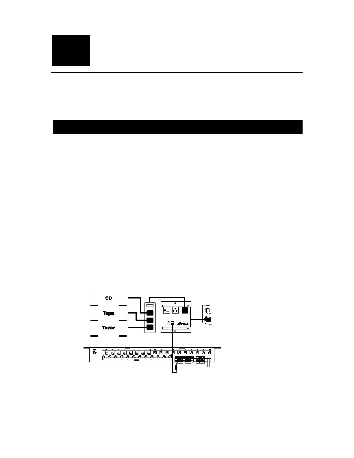
1. 12V DC Sync via a Wall Adapter Plugged into a Switched AC Outlet
Many preamps, integrated amps, receivers, surround-sound processors, and cable TV
descramblers have a switched AC outlet (i.e. the outlet is hot when t he preamp is “on”,
and dead when the pream p is “off”) to automaticall y power up components with latch ing
power. In an IntelliControl system, the switched outlet may be expanded with an extension
cord or power strip to accom modate a 12V DC 200mA wall adapter and any “latching
power” components you ma y be using . T he output of the wall adapter is conn ected to the
IntelliControl’s dedicated “Preamp 12V” sync input.
13
Page 19

2. Niles LS-1 Light Sensor
The Niles LS-1 Light Sensor was designed to detect a change in brightness on a
component’s front panel display. When it senses a change in brightness, the LS-1 outputs
a constant 12V DC 500mA control voltage. A blocking cover is provided to prevent
ambient light from falsely triggering the LS-1.
Note: You may choose to sync direct-view or rear-projection televisions with the LS-1 Light
Sensor. In this sync applic ation, the L S-1’s sensor is attached to th e rear of the T V us ing
the blocking cover (or better yet – to t he flyback transfor mer inside the TV . The Flyback
transformer resembles a auto mobile alternator and is loc ated near the TV’s main power
supply and AC power cord c onnection). The L S-1’s sensitiv ity is adj usted to o utput a 12v
DC sync signal only when the TV is on.
Additionally, when syncing mul ti-disc CD chang ers or other digital compon ents, it may be
possible to install the L S-1’s sensor inside the component ’s optical digital outp ut jack to
detect the presence of light comin g from that port when t he unit is powered o n. The unit
must not emit any light from this port when the unit is in standby!
3. Niles OTI-512 Voltage Sensor
The Niles OTI-512 Voltage Sensor senses any control voltage between 3 and 30 volts AC
or DC, and outputs a 12V DC 500mA c ontrol vol tage. T he 12V DC output is connected to
the IntelliControl’s sync input dedicated to that component.
An accessory cable (the Niles FOS-512) will connect a Fosgate, Lexicon, Citation, or
Synthesis preamp to the OTI-512.
4. Niles APC-2 Current Sensing Switcher
The Niles APC-2 Current Sensing Switcher senses any change in power consumption
that is greater than 30 watts. W hen it senses that the power c onsumption has increas ed
(by the component turning on), it outputs a 12V DC 300 mA control voltage. In an
IntelliControl system, the component’s AC power plug is plugged into the unswitched
“Sensing” socket on the APC-2. The 12V DC output is connected to the IntelliControl’s
sync input dedicated to that component.
The APC-2 has several other f eatures. For more info, please l ook up the APC-2 on our
website: www.nilesaudio.com
5. Niles IPC-6 Current Sensing AC Power Controller
The Niles IPC-6 Current Sensing S witch senses any chang e in a component’s power
consumption that is greater than 3 watts. When it senses that the power cons umption has
increased, it outputs a 12V DC 300mA control voltage. In an IntelliControl s ystem, the
component’s AC power plug is connected to the unswitched “Trigger” socket on the IPC-6.
The 12V DC output is connected to the IntelliControl’s sync input dedicated to that
component.
The IPC-6 is not an iPower surge suppression device, but it does have several other
useful features. For more info, please look up the IPC-6 on our website:
www.nilesaudio.com
14
Page 20

Each Sync Connection on the Main System Unit Corresponds to a Pa rticular Master Key on the Tabletop Remote
The labels typically repres ent the sources of a s ystem. Master Keys 1 through 7 f eature
both “12V” and “Video” sync capabilities, Master Key 8 features only “12V” sync, but
Master Keys 9 and 10 have no sync co nnections at all. For each com ponent, you must
utilize a Master Ke y which has the nec essar y sync capabilit ies. T he pream p/receiver and
the television monitor do not need a Master Key assigned to them (but you may choose to
assign Master Keys to the receiver’s AM/FM tuner and the TV’s internal tuner). T he TV
monitor and Preamp ar e system components that are needed to lis ten to and watch a
component. Therefore, they have been permanently assigned their own sync connections.
PRE - The surround-sound preamp/receiver for the system is assigned the “PRE 12V”
sync connector.
TV - The Television Monit or for the s ystem is as signed to either t he “TV 12V” or the “TV”
Video Sync connector. Note: The “TV” Video Sync connection method is reliable only if the
TV you are using has a “Tuner ” output. Using the TV’s “Mon itor” or “Video” o utput is not
reliable.
MASTER KEYS ONE through SEVEN - T hes e Mas ter Keys ar e ass igned both “1 2 V” and
“Video” sync connections.
LABEL EIGHT - This Master Key is assigned a “12V” sync connection only.
LABEL NINE and TEN - These Master Keys do not f eature any sync connections at all.
However, these keys may be used as Master Ke ys if their components have “latching
power” or separate “On” and “Off” commands.
Figure 8 Master Key Sync Features
Conventional Labeling Rule: Video on the Left, Everyth ing Else on the Right
Since most video com ponents r equire s ync, it is conve ntional t o use th e left han d co lum n
for video sources, and ut ilize the right hand colum n for the res t of the system. T ypically,
audio sources, sources with built-in or latching power , components wh ich are always o n
(i.e., lighting controllers), and manually controlled features are usually configured to master
Keys on the right side of the Tabletop Remote.
15
Page 21

Once Again: Remember the Exception
Since the IntelliControl will be programmed to turn on the T V Monitor whenever a video
Master Key is pressed, there are a special set of sync connectors dedicated to the TV and
are unrelated to any of the other Master Keys. Likewise, the Preamp/Receiver has its own
Preamp sync and flasher connections unrelated to any of the other Master Keys.
If the television’s built-in tuner is a source fo r the system or if the receiver’s built- in AM/F M
tuner is a source, Master Keys do need to be assigned. However, even though the TV and
the Preamp need sync, the Master Keys for their internal tuners do not need sync
(because they represent the components which are built into the TV and the Preamp). The
IntelliControl will autom atically check the sync of the Preamp when the “AM/F M” Master
Key is pressed, so it is not necessary to check the sync for the receiver’s tuner as well.
Because of this, you may assign the lab els “TV” and “AM/FM” to any of the ten M aster
Keys (including Master Keys 9 and 10), since sync for those sources is not necessary.
2C. Component Compatibility
Infrared Compatibility
All audio/video components in the system must be rem ote- contr olled by infrared (IR). The
system was designed to be compatible with virtually any brand of equipment that transmits
IR commands on carrier frequencies bet ween 2 6kHz and 110kHz, as well as 455kHz (i.e.
the IntelliControl is compatible with Bang & Olufsen).
Niles has compiled an extensive IR Library of over 175 different products from most of the
major manufacturers (including m any direct access and separate “On/Of f” codes). Earlier
versions of the IntelliFile II CD-RO M do not inclu de the extended IR Libr ary, so call N iles
Tech Support at 1(800)289-4434 with your email address and we will email it to you!
Before an IntelliControl i nstalla tion is propos ed to a cus tom er, it is s trongl y recom m ended
that you check the equipment list for c ompatibility. As a general r ule, if the component’s
codes are capable of being taught to a standard “learning” remote control (Pronto,
RC2000, SL9000, etc.), the IntelliFile II will be able to learn them.
Note: If a product’s codes do not w ork reliably when taught to a learn ing remote, “A/B”
codes could be the cause. A s mall perc entage of vide o projectors an d other com ponents
feature Philips RC-5 codes. This type of IR code structure has been known to exhibit “A/B”
behavior in some products, and may be incompatible.
To be brief, these products have two different codes for each button on the remote, the “A”
version and the “B” version. The pr oduct must rec eive alternat ing (A/B/A/B, etc.) ver sions
of its codes or it will not respond. It doesn’t matter what c ode is iss ued (or in what order),
because the remote and the product will keep trac k (technical ly there’s mor e to the story ,
but this is the basic princ iple). Sinc e the IntelliF ile II (and the Inte lliControl MSU) can on ly
store one version of each c ode in m emory, on ly the “A ” or the “B” v ersio n c an be lear ned
and stored in memory, which creates a problem.
16
Page 22

The following procedure will help you determine if the component you are using is has
“A/B” codes:
1. Standing in front of the component, issue the “Power” command to turn it on. This will
theoretically issue the “A” version of the “Power” command.
2. Next, completely cover the front of the remote with your hand so that the next
command you issue will be blocked.
3. With your hand covering the front of the remote, issue the “Po wer” command again.
This command will theoretically be the “B” version, and should not be allowed to
reach the component. The component should remain “On”.
4. Remove your hand and issue the “Power” command again. This will once again issue
the “A” version of the code to the c omponent. If the component does not turn “Off”
(because it has received two “A” version codes in a row) the codes may be “A/B”.
5. Issuing the “Power” comm and yet again should turn the unit “O ff”. This would allow
the component to receive its “ B” version “Power” command, and enable it to work
properly.
Repeat this procedure with a c ouple of different commands to be sure. Onl y allow the
product to receive every-other c ommand. If you are c onvinced the pro duct you are using
has “A/B” codes, call Niles Technical Support at 1(800)289-4434 for assistance.
Testing Components for Automation Conflicts
All components mus t be tested to ensure that their operation does not c onflict with the
goal of automating the system. Try to detect IR codes that have two functions. Sometimes
this could help you automate the s ystem (i.e. a direct IR command f or a particular input
also turns the unit on. This feature is common with some Marantz and Sony receivers).
In some instances, however, th ey def eat autom ation (i. e. ADA m anufac tures a pr eamp in
which the “Mute” command mutes the pream p, but does not unmute it. A second touch of
the “Mute” key turns the preamp off).
Testing Components for Sync Method
Each component must be “Sync Tested” to determine if it will correctly signal the
IntelliControl that it is on or off , using the s ync m ethod specif ied. You c annot ass um e that
a sync method will work properly. The following notes will alert you to common sync
problems encountered in the field.
Important! Every component which us es an IR command to turn on or off needs to be
synced to the IntelliControl, and sync tested for reliability.
It is a common mistake to omit sync for a component which uses two separate IR
commands – one comm and to turn “On”, and a diff erent command to turn “Off” . Without
sync, the IntelliControl will not know that an “Off” command is necessary when the
“System Off” Key is pressed, and the component will not be shut off. Additionally, an
unnecessary delay of 2 s econds will oc cur every time that com ponent is selected with its
labeled Master Key, even when the system is already on.
17
Page 23

Sync Off Delay
It is common for man y video components s uch as VCR’s and DS S receivers to c ontinue
to output video for a few sec onds ( or long er) af ter the y have b een t ur ned of f . This creates
a false sync signal and may interfere with reliable operation. It is important to note duration
of the component’s “Sync Off Delay”, and discuss this with the installer and the end user.
If a Master Key is pressed im mediately after the “System Off” key is pressed, the false
sync signal may prevent the Inte lliControl from turning on that c omponent. To maintain
sync during operation and tr oubleshooting, it is important that b oth the installer and the
end user know how long they must wait before the s ystem can be turned back on after a
System Off command has been issued. This problem can be eliminated by including a
delay (of whatever duration necessary) in the Ending Sequence of the “System Off” key.
This problem can reach epic pr oportions when us ing an APC-2 t o current-sense an LCD
projector. Most LCD projectors require the internal fan to stay on for as long as ten
minutes after the projec tor is turned off. This may trig ger the current sensing devic e to
send a false sync signal for ten minutes!
Attempt to adjust the current sensing dev ice to reduce the sync dela y to a few seconds
after the projector is turned of f. If this is not possible, change to a different sync m ethod
(such as the LS-1 Light Sensor).
Testing the Switched AC Outlet
Make sure that the switched outlet actually switches “O n” and “Off” with the c omponent’s
“power” command. Two 1995 model Harman Kardon receivers (the base model Pro-Logic
and the base model stereo receiver) and the 1995 b ase model Denon stereo receivers
advertise “Switched” AC outlets . Ho wever these “ switched o utlets ” do not t urn on and of f
with IR commands. they only switch with the front panel “Power” button. For products with
this type of “pseudo-switched” outlet, a Niles LS-1 Light Sensor or the APC-2 Current
Sensor must be used to provide reliable sync.
Testing the Video Output of a Source
Make sure that the video signal turns off when the component is turned off with an IR
command. Some video co mponents output a video signal e ven when off. This can be
difficult to detect with a television s ince some televisions generate a blue sc reen when
there is no input (which is why use of the TV’s “Tuner” output is recommended). To reliably
test for video sync, you will need an IntelliControl Main System Unit, the IntelliFile II
Programming Software and PC I nterface, the RF/IR Test LED, and the Transfer Cable.
Follow these steps to test for video sensing:
1) Hook the video com ponent to the video sync port that corres ponds to its Master Ke y
label.
2) Connect an RF/IR Test LED to the RF Test port on the Main System Unit.
3) Power up the Main System Unit.
4) Power up and connect the Inte lliFile II PC Interface to the M ain System Unit with the
supplied Transfer Cable.
18
Page 24

5) Click on the “Com ponents” tab in IntelliFile II and select the com ponent you wish to
video sync test.
6) Go to “Sync Test” , selec t “Video Synced”, and click the “On” button. ( The IntelliFile II
will stay in video sync mode for the component being tested until the “Off” button is
selected).
7) Turn the video com ponent “On” and “Off” manually (or with the rem ote). The RF Test
LED should be green when it is “On”, and red when it is “Off”.
If the Test LED displays a red LED when the video component is “On” ( or a green light
while the component is “Off”...) you must utilize an LS-1 Light Sensor or the APC-2
Current Sensor to provide reliable sync.
Testing the Video Output of a Television
Use the TV’s “Tuner” output if the TV is equipped with one. If the TV has only a “Video” or
“Monitor” output, will have to resort to another sync m ethod. A TV’s “Monitor” output wil l
only give reliable sync if the television ’s inp ut is ne ver c hang ed t o an input without a video
signal present. However, if you select a video input connected to a device that happens to
be “Off” (video games , computers, etc.), the IntelliC ontrol will be f ooled into think ing that
the television is “Off”, when it is, in fact, “On”. Test to be sur e. If the “Video” or “Monitor”
output is not reliable, use an APC-2 to current sense and provide 12V sync.
Testing Light Sensing
Make sure that some portion of the front panel display dims when the component is turned
“Off” with an IR command. If a product were to be manufactured with a display that simply
changes color, light sensing s ync would not be reliable and an APC-2 or IPC- 6 current
sensor should be specified.
Testing Current Sensing
Make sure that the APC-2 reliably senses the difference between “Standby” and “On”. The
component must have a 30 watt difference between “On” and “Off” (or “Standby” and
“On”) to be reliable. If the current difference is less than 30 watts, the IPC-6 Current
Sensing Power Manager or th e LS-1 Light Sensor should be specif ied. The IPC-6 can
sense a 3 watt difference between “Standby” and “On”.
Testing a Component’s Control Voltage Output
The OTI-512 voltage converter outputs a 12 V DC volt age when ever a ny vo ltage bet ween
3V and 30V AC or DC is output f rom the component. Make sure that the component’s
voltage output reliabl y turns on and off in sync with the IR comm ands. Some components
have voltage outputs that are onl y present when a component is in a particular m ode of
operation. This will cause the system to get out of sync if it happens to be in another
mode. Use a voltage that is present in all modes of operation and is not present when t he
component is “Off”, or simply specify another means of syncing the device.
Testing Dual Zone Preamp/Receivers
Most dual zone preamp’s switched outlets are n ot ab le to provide reliable sync f or j us t the
Home Theater zone (unless it on l y switc hes on when th e “ T heater ” zone is active and not
19
Page 25

when “Zone 2” is active). Bec ause of this, it may not be possible to s ync the receiver
using a 12V DC wall adapter. Ins tead you must res ort to using dual zone receivers with
separate “On” and “Off” commands for the “Main” and “Second” zones, configurable
control voltage outputs, or sim ply use two separate r eceivers. An LS-1 Light Sensor m ay
be used if there is a wa y to detec t when the Home Theater zone is on inde pen dent of the
Second Zone.
Connect the dual zone component so that you can listen to mus ic on both zones . T ur n on
the “Second zone”, then turn the “Home Theater” zone “On” and “Off”. You may be able to
position an LS-1 Light Sensor on the por tion of the disp la y that brightens when the H om e
Theater zone is on. Turn the Home Theater zone “On” and “Of f” and observe the LS-1’s
LED to see if you can get reliable sync (gr een lights on your T est LED). T his tes t will only
be valid if you repeat the tes t with the display in every possib le configuration, with any
input selected, and with the Second Zone “On” and “Off”.
20
Page 26

Chapter
3
Programming Capabilities
3A. Pages, Ke ys, and Sequences
Designing and programm ing an IntelliControl system requir es that you have an intim ate
understanding of how the IntelliControl functions. This way you can sell the system
properly (and not embarrass yourself by m aking unrealistic pr omises), as well as be able
to quickly and efficientl y program the s ystem so the c ustomer gets the maximum amount
of enjoyment from his investm ent. In the followi ng sections, t he operatio nal ca pabilities of
each key are described, and the overall architecture of the IntelliControl product is
explained.
The IntelliControl’s memory is divided in two sections. One section stores all of the
“Automation” (including all “Power” commands, “Input Selection”, etc.), and the other
section of memory is divided into “pages ” f o r s tor age of all of the r emaining IR commands
which the user may issue to control the features and functions of the components, as well
as peripheral devices in the system.
Note: It is not important that you learn how to program the func tions described below at
this time. Simply concentrate on understanding the general concepts, and explicit
programming instructions will be explained step-by-step in the IntelliFile II Reference
Manual Version 1.0.
Figure 9 The IntelliControl Tabletop Remote
21
Page 27

An Address For Every IR Command
Every command you want the IntelliControl to issue must be stored to a memory address
(including commands that are only issued as steps in a sequence). Every memory
address is composed of two parts, th e “ Key” you are pressing, and the “Page” you are on
when that “Key” is pressed.
The “Key” is the actual k ey you would press on the Inte lliControl’s T abletop Remote (i.e.
“Play”, “Stop”, “Pause”, “ Volume Up”, etc). T he “Page” describes one of thirteen diff erent
layers of memory storage (there are ten user-accessible “ Master Key Pages” for sour ce
components or features, plus three additional pages called the “Special Pages”. The
“Special Pages” include the “Library 1”, “Library 2”, and “Default” pages, which will be
discussed late r. Explicit instructions for programming “Function Key IR” commands can be
found in the IntelliFile II Reference Manual starting on page 9.
Once the ten Master Keys are labeled, all of the k eys on the right side of the Tabletop
Remote will be referred to as the “Function Keys”. “Function Keys” correspond to the
currently selected “Master Key Page”. Not only does the pr ess of a Master Key ini tiate all
of the necessary automation required to enjoy the selected s ource, it also configur es the
system to enable you to selec t any of the “Function Keys” on the r ight two-thirds of the
Tabletop Remote and control the currently selected source. Thus the VCR’s “Play”
command is typically stored on the “VCR M aster Key Page” in the “Play Key” mem ory
address.
Issue A Sequence From A Function Key
If desired, every “Ke y” on every user-ac cessible “Page” may be programm ed to trigger
either a single “Function Ke y IR” comm and, or “F unction Key Sequenc e” of up to twent ysix IR commands. The key that the user will press to issue the sequence is referred to as a
“Trigger Key” in the IntelliFile II software. Thus if you wanted t he “VCR” page ’s “Pla y” key
to issue a sequence, you would c onsider the VCR page as the “Trigger Page”, and the
VCR page’s “Play” button as the “Trigger Key”.
Note: As previously mentioned, each memor y address may be programmed to store a
single “Function Key IR ” command, as well as to tr igger a “Function Key Sequence” if
programmed to do so. Therefore, a “Function Key Sequence” may be triggered by a
tapping a Function Key (i.e. by pressing the “Play” key on the “VCR” page).
However, the “Function Ke y Seq uence” will a l wa ys tak e pr ior ity. Th e actua l “ Func tion Key
IR” command stored to the “Play” key address is not er ased, and m ay be includ ed in this
sequence (or any other sequence). This means that if you want the VCR’s “Play”
command to be issued as one of the steps in a “Function Key Sequence”, the VCR “Play”
command must be included as one of the steps when the sequence is programmed.
When a “Function Ke y” is pressed, the I ntelliContr ol firs t checks to s ee if a “Func tion Key
Sequence” has been programmed to be triggered by the selected Function Key. If a
sequence has been programmed, it will be initiated. If a sequence has not been
programmed to be initiated by t he selected Function Key, the single “Function K ey IR”
code stored to that “Page” and “Key” address will be issued.
22
Page 28

Therefore, you could first program the “Play” key on the “VCR” page with the VCR’s
“Play” Function Key IR command (which plays the VCR), then you could program the
same key to issue a sequence consisting of two steps - the VCR’s “Play” command,
followed by the LIGHTS “D im” command. Note: Each actua l step has two parts, “a” and
“b”. The overall flow is as follows:
1a. Identify the “MASTER KEY PAGE” on which the “Trigger Key“ that will trigger our
sequence is located. In this example we will select the “VCR” Master Key.
1b. Identify the “TRIGGER KEY” (on the currently selected page) that will trigger our
sequence. In this example we will select the “Play” Function Key.
2a. Identify what “PAGE” the FIRST command in our sequence is stored on. In this
example, the “Page” (where the first command is stored) will be the “VCR” Page.
This will be the same “page” as Step 1a, but ONLY if the first command in the
sequence will be the same as the sequence trigger.
2b. Identify what “KEY” (on the currently selected page) the FIRST command in our
sequence is stored on. In this example, the “Play” button is where the first command
in our sequence is stored. This will be the same “key” as Step 1b, but ONLY if the
first command in the sequence will be the same as the sequence trigger.
3a. Identify what “PAGE” the SECOND command in our sequence is stored on. In this
example, the “Page” (where the second command is stored) will be the “LIGHTS”
Page.
3b. Identify what “KEY” the SECOND command in our sequence is stored on. In this
example, the “#1 digit” is where our second command is stored. (In this example, the
actual code will be a Lutron Grafik Eye scene command that has been stored on the
“Lights” Master Key page, to the “#1 digit” Function Key location).
If your sequence consists of more than two steps, simply repeat ste ps 3a and 3b. The
concept of sequence programm ing is very straig ht-f orward as lo ng as you al ways think of
each step as having two parts, the “Page” and the “Key”.
Note: This is the exact same concept used with the Niles IntelliPad Programmable
Keypad, and applies to both m anual pr ogramm ing and pr ogramm ing usi ng Intel liFile II for
IntelliPad.
Purpose of the Master Key Pages
The ten Master Keys decide which “page” of IR command memory will be accessed.
When a Master Key is pres sed, the Function Ke ys (on the right sid e of the r emote) now
access that page of IR comm and memor y. For example, when th e “VCR” Master Key is
pressed, the “Play” key will play the VCR, and when the “DVD” Master Key is pressed, the
“Play” key will play the DVD. There are ten labeled Master Keys, each selecting a page of
memory with up to 32 individual IR commands on each page. This gives you a total
possible 320 addresses f or IR comm ands for manual oper ation of the com ponents in the
system.
Purpose of the Default Page
If you choose not to program a “Function Key IR” command or a “Function Key Sequence”
to any specific key on any of the ten Master Key pages, the IntelliControl will automatically
23
Page 29

look to that memory address location on the “Default” page of memory to see if a
“Function Key IR” command (or a “Func tion Key Sequence”) is stored there. If there is
information programmed to that particular address on the “D ef ault” page, the IntelliControl
will issue whatever code (or sequence of codes) is stored there.
Therefore, the “Default” page is the memory location for IR commands which are universal
to all of the components in the Ho me Theater system. An exam ple of this would be the
Preamp/receiver’s “Volume Up and Down”, and “Mute” commands. You simply do not
program any IR commands to the “Volum e Up/Down” a nd “Mut e” Ke ys on the ten sour ce
pages, and let the IntelliControl issue the commands stored to those locations on the
“Default” page.
If the user constantly adjusts picture or surround-sound, you could choos e to assign the
“Menu” group of keys as a universal feature, so that no matter what Master Key is
currently selected, the “Menu” keys will access the customer’s desired functions.
Purpose of the Library Pages
There are two additional pages of memory addresses called “Li brary 1” and “Library 2”.
The “Library” pages are o nly used to store codes which will be includ ed in sequences.
Codes taught to the Library pages are not directly accessible by the end-user (unless they
are included in a sequence, of course!).
3B. Function K ey Memory Limitations
The IntelliControl has thirt een pages in total, with 32 Fu nction Keys giving you 416 total
possible Function Key addresses including the “Default” and “Library” pages. Of those 416
addresses, only 320 addresses are accessible for manual operation by the end-user.
The IntelliControl ships with a 1 Meg abit chip for IR code storage f or the Function Keys,
and has an empty socket for a second 1 Megabit chip. You can order an additional
memory chip for especially large and complex systems (FG00735). Depending on the
brands you are using, the built in memory will enable you to learn between 284 and 475 IR
codes.
Note: Typically, since many address locations go unused, less than 200 IR codes are
taught to Function Key addresses and the additional chip is not needed. The configuration
memory used for the Master Keys is completely separate and cannot be exhausted.
The following is a list of the estimated maximum number of IR codes that can be stored in
one memory chip if all of the codes are from one of the following brands:
Denon 378
Harman/Kardon 475
Lexicon 378
Marantz 475
Mitsubishi 284
NEC 378
(More than 50% of all Audio/Video
remote controls use NEC codes)
Onkyo 369
Pioneer 378
24
Page 30

Sony 369
Yamaha 378
The addition of the second c hip gives far more capacit y than needed (it ess entially g ives
the memory the capacity to store more than 1200 IR codes, when there are only
addresses to store 416). T he Intel liFi le II sof tware will indicate that you ar e ou t of memory
when the text describing the codes you ar e draggin g and dr opping into your conf iguration
turns red. For more information on what happens when you run out of memory, see
Memory Usage on page 28 of the IntelliFile II Reference Manual.
If you do manage to legitim ately run out of memory (see Memory Usage above), You
may continue to program with your software, but do not attempt to transfer the program to
the MSU until after you have added the second chip. If you do, the codes will be
scrambled and your system will experience extremely erratic operation.
Note: Some manufacturer’s codes (including Panasonic, RCA, and Pioneer) eat up
excessive memory. Be sure to te ach these codes w ith quick bursts from the remot e. DO
NOT PRESS AND HOLD WHILE TEACHING THESE COD ES. Certain codes (Volume,
FF / Rew, etc.) require a “press-and-hold” of the button to learn and operate properly. Only
hold the button as long as nec essary to ensure proper operatio n. It is strong ly sugges ted
that you test all codes as you teach them!
If you unexpectedly run into the Memory limit and must get the system partially operational
for the customer until the Memory Upgrade chip arrives, the best strategy is to erase a few
IR commands, and transf er the program to the MSU with lim ited manual operation. Then
phone the office and have them order the Memory Upgrade (FG#00735).
When the Memory Upgrade Chip arrives, go back to the jobsite and complete the
programming. Note: The Memory Upgrade (or lack of memory) does not affect the
automation that occurs as the system is powered up and shut down, it only affects the
ability to store an additional number of IR codes in the Functi on Keys’ memory addres s
locations.
3C. Master Key Auto matio n: Part 1 - One T ouc h System T urn On
By pressing a Master Key, the end user will trigg er the following programm ed “Events ” to
occur. These events are displayed in the “Master Key Navigator” f eatur e of the Intel liFi le II
software. The “System Turn On” automation will power up and configure the home theater
system based on the actual stat us of the components at the time the Master key was
pressed.
Note: “System Turn On” automat ion is an autom atic function of t he IntelliControl System.
DO NOT attempt to manually progr am the “ System Tur n On ” automation by including the
TV, Preamp, and Component power commands in the “Ini tial Sequences ” for the Master
Keys. This will bypass all the sync features an d the built-in intelligence w hich has made
the IntelliControl such a successful product.
The “TV Power”, “Preamp Power”, and “Component Power” commands are entered on
their respective “Tabs” in the IntelliFile II software. The appropriate “Power” commands are
automatically issued based on the “Audio Scene”, “Video Scene”, and “Component
Power” programming which is configured on the “Components” Tab in IntelliFile II. For
more Information, see Scene Setting on page 25 of the IntelliFile II Reference Manual.
25
Page 31

Sync Snapshot
As soon as a Master Key (or the “System Off” Key) is pressed, and before any commands
are issued, the IntelliControl MS U takes a “Sync Snapshot” of all the s ync ports on the
MSU. By taking this “Snapshot”, the MSU is essentially taking inventory (roll call!) to
determine exactly which com ponents are on and which com ponents are off at the exact
moment the Master Key was pressed.
The MSU then takes the inf ormation it gathers during the “Sync Snaps hot” a nd c ompares
it to the automation information you have programmed for that Master Key. The
IntelliControl will then intelligentl y reconfigure the system to enable the user to enj oy the
selected source. This automation programming can be viewed via the “Master Key
Navigator” feature by clic king on the View button next to each Master K ey name on the
“Master Keys” Tab in IntelliFile II. The “Navigator” contains the entire s et of programm ing
instructions that must be executed in order for the user to enjoy the selected source.
Figure 10 The Master Key Navigator
Event One – Initial Sequence
The “Initial Sequence” is issued without regard to sync, and is gen erally used to issue
commands to peripheral devices in the system (i.e. screens, lifts, drapes, masking
devices, lighting controllers, etc.).
Note: “Power”, “Input” and “Mode” commands should not be placed in the “Initial
Sequence”, as these commands will be issued without regard to sync.
26
Page 32

Event Two - TV Power
In “Event Two – TV Power”, the IntelliContr ol check s the autom ation programm ing of this
particular Master Ke y. Should the T V turn “O n” when this Mas ter Ke y is pr ess ed? Should
the TV turn “Off” when this Master Key is pressed?
Once the IntelliControl has checked it’s instructions, it refers to the “Snapshot”. If the
“On/Off” status of the TV is different from the instr uctions, the IntelliContro l will issue the
necessary “Power” command to the TV .
Event Three - Preamp Power
When the IntelliControl reaches “Event Three, Preamp Power”, the IntelliControl checks
the automation programm ing for this particular Master Key. Sh ould the Preamp turn “O n”
when this Master Key is pressed? Should the Pr eamp turn “ Off” when this Master Key is
pressed?
Once the IntelliControl has c heck ed it’s ins truct ions, it then r efer s to the “ Sync Snaps hot”.
If the actual status of the Pream p is different from the instruct ions, the IntelliControl will
issue the necessary “Power” command to the preamp.
Event Four - Component Power (Not Applicable to Master Keys Nine and Ten)
When the IntelliControl reaches “Event Four, Component Power”, the IntelliControl will first
check the programm ing of this particular Master Ke y. Should the c hosen c omponent turn
“On” when this Master Key is pressed?
Once the IntelliControl has c heck ed it’s ins truct ions, it then r efer s to the “ Sync Snaps hot”.
If the “On/Off” status of the component is different than that of the instructions, the
IntelliControl will issue the necessary “Power” to turn on the component.
Event Five - TV Input
The IntelliFile II software features three m ethods to change the TV’s inputs. See details
starting on page 32 of this manual.
Event Six - Preamp Input
The IntelliFile II software features three methods to change the Preamp’s inputs. See
details starting on page 32 of this manual.
Event Seven - Surround Mode
The IntelliFile II software features three methods to change the surround-sound modes on
the preamp. See details starting on page 32 of this manual.
Event Eight - Ending Sequence
The “Ending Sequence” is used to issue commands that need to be issued after the
IntelliControl has turned on the components and selected inputs and modes. IR
commands included in the “Ending Sequence” are issued without regard for sync.
27
Page 33

Typically, “Play”, “Digit” commands (used to select the users favorite channel), and
occasionally “Stop” com mands (for other components in the system) are included in the
“Ending Sequence”.
3E. Master K eys: Part 2 - Special F eatures
Automation Bypass for Manually Adjusted Features
Additionally, you m ay choose to utilize the IntelliFile II’s “Aut omation Bypass” feature b y
selecting Leave TV Alone and Leave Preamp Alone under “Scene S ettings” on the
“Components” Tab.
®
The IntelliFile
Master Key to be used as a “Feature Key”. Setting a Master Key up as a “Feature Ke y”
enables it to control dev ices or functions which are not source components, but simply
functions of a sourc e, or functions of a peripheral device (i.e. a lig hting control system,
mechanical drapes, projection screen, masking devices, etc.).
After the “Feature Key” has be en selected and the desir ed com mands have be en issued
from the “Feature Key” page (“s ingle” IR commands or a “Function Key Sequence” m ay
be issued from the “Featur e Key” page), you ar e able to reselec t the origina l Master K ey
for the source you are watching t o regain control over the functions of that source. The
system will not reconfigure itself to the original Master Key’s default settings.
II’s “Automation Bypass ” feature would be useful if you wanted a certain
Note: If a different Master Key (other than the one s elected before the Feature Key was
pressed) is chosen, the “Aut omation Bypass ” feature will not work as described, and the
system will reconfigure itself to its default settings for the newly selected Master Key.
By configuring a Master Key as a manually controlled “Feature Key”, the “Automation
Bypass” feature becomes a useful part of a system design whenever manual control of the
system’s features (as well as automation) is desired.
Automation Bypass for a Typical Application
Normally, when the “CD” Master K ey is pressed, the Int elliControl
®
will set the system ’s
Surround Sound Mode to “Stereo”. However, you may label one of your Master Keys as a
“Surround Sound Feature Key” so the end-user m ay select a source and then manuall y
change the surround mode from its default setting.
This is accomplished by programming the “Surround Sound” Master Key to Leave the TV
alone and Leave Preamp alone, which will e nab le the “ Automation Bypass” feature. You
then program the IntelliControl
®
’s numeric keys on the “Surroun d Sound” page to enable
direct access to the pream p’s different DSP surr ound modes (i.e. Concer t Hall, Stadium,
Jazz Club, etc.).
A typical listening sess ion might go something like this: You pres s the “CD” Master K ey
and the system com es to life correctly configured to Stereo Mode. After listening f or a
while, you decide that one of your processor’s digital sound fields would be very well
suited to the CD you are listeni ng to. You press the “Surround Sound” Master Key and
experiment with different modes until the sound is perfect.
28
Page 34

However, if the user decides to skip a song on the CD, you simply reselect the “CD”
Master Key to access the song skip button. Normally this would reset the system to
Stereo, but since the “Surround Sound” Master Key was programmed as a “Feature Key”,
the IntelliFile II’s “Automation Bypass” feature is engaged, and the preamp will not be reset
to Stereo mode.
Since the “CD” Master Ke y was the last source selected befor e pressing the “Surroun d
Sound” Master Key, the normal steps the CD Master Key would trigger to reset the
surround mode to “Stereo” are b ypassed. If you were to press any of the other Master
Keys (rather than the last selected, which would be “ CD” in this exam ple), the autom ation
would not be bypassed and the system would continue with normal operation and
configure the system to the default surround mode for that newly selected Master Key.
How to Program “Component Power” for Multiple Master Keys which Share a Common Source
It is possible to use more than one Master Key to automaticall y turn on and control the
same source. One example might be multiple Master Keys (labeled HBO, Showtime,
Disney, ESPN, etc.) that are all turning on and controlling the same DSS receiver.
However, the ending sequence for each of the Master Ke ys is programmed to select a
different channel.
Another example would be a system with a Pioneer combination DVD, Laser and CD
player. You would label three Master Keys for the three f unctions in the m achine, so that
you can program the Surround Sound Mode to be “Dolby Digital” wh en the DVD key is
pressed, “Dolby ProLogic” when the Laser Disc key is pressed, and “Stereo” when the CD
key is pressed.
There is an “Installation T rick ” and a “Program ming T rick” which ne ed to be per formed in
order for the component to turn on and off as the end-user would expect:
Installation Trick
You must split the shared source component’s sync output to each of the appropriate sync
connections for each Master Key that will be used to aut omate and control the shared
component. This will enab le the MSU to accurately m onitor the s ync status of the shared
source from any of the Master Keys.
Programming Trick
Note: this “Programming Trick” is only neces sary if the com ponent be ing shar ed util izes a
single ”Toggle” power comma nd to turn the uni t “On” and “O ff”. If the compone nt you are
using features “Separate On and Off” comman ds, simply program each Master Key as
you normally would.
The IntelliControl Tabletop Remote features ten Master Keys, which are numbered 1
through 5 in the left column, and 6 through 10 in the right column.
For the Master Key with the lo west number (out of the IntelliControl’s ten p ossibilities),
program the component’s “Power” comm and in the standard way. Meaning that on the
“Components” tab in Intell iFile II, when the you are ask ed whether th e com ponent us es a
single “Toggle” command, or “Separate On/Off” power comm ands , ans wer “Toggle” (one
“single” power command).
29
Page 35

For all of the other Master Keys with higher numbers (out of the IntelliControl’s ten
possibilities) which will automatically turn on the shared source component, choose
“Separate On/Off”.
Even though the component only features a single “Toggle” power command, this
technique will enable us to trick the IntelliControl into proper operation by programming the
component’s “Toggle” power” IR command into the “On” location, and a bogus IR
command (such as “play”, or any command belong ing to a com ponent not being used in
this system) in the “Off” location. Note: Once again, this programming “trick” is
unnecessary if the component uses separate “On” and “Off” commands.
Press and Hold a Master Key
Optionally, the ten labeled Master Keys may be programmed to trigger an additional
“Function Key IR” command, or a “Function Key Sequence” of up to 26 steps, whenever a
Master Key is “pressed and held” for more than one second.
This function of the system is completely independent of the Master Key automation
programming that occur s when the Master Key is s imply “tapped”. Note: If the system is
not active when a Master Key is pressed and held, the normal intelligent automation
programming will be bypassed, and only the “Press and Hold” IR command (or sequence)
will be issued. Additionally, this IR command (or sequence) will be issued without regard to
syn c.
Typically the “Press and Hold” feature is used to provide the end user with a way to
manually turn a particular component “ On” or “Off”. It is frequently only progr ammed for
the TV Master Key, so that the user can turn on the system with a video source
(automatically switching on the TV), then s witch to listening to an audio source (t he TV
could be programmed to remain on), and then finall y decide to continue to listen to the
audio source with the TV “ Off” by pressing and holdi ng the TV Master Key. The ins taller
has programmed the “Press and Hold” function of the TV Master Key to issue the T V’s
“power” command when that key is pressed and held.
Should the end user desire the ability to manually issue “Power” commands to all of his IR
controlled sources, eac h of the Master Keys could be programmed via the “Press and
Hold” feature with the IR “power” comm and for each source. Once again, the “ Press and
Hold” feature may also be used to initiate a s equence of up to 26 comm ands (including
delays and contact closures/openings) from any of the ten Master Keys.
Custom Programming for Preamp/Receivers with Separate On/Off Commands
Several manufacturers are currently offering preamps/receivers with cool features like
“main” and “second” zone capabil ity, separ ate “On” and “Of f” comm ands for these zones,
as well as rear-panel hardwired IR inputs for each zone.
This enables you to custom program the IntelliControl by not programming “Preamp
Power” the traditional way, but instead by teaching the “On” and “Off” codes to the
“Library” pages so that the Preamp’s “ Separate O n” c om mand can be added to the “Initial
Sequences” of every Master Key. You may then include the “Off” command as a
sequence step to the “System Off Initial or Ending Sequence”.
30
Page 36

3F. Master K eys: P art 3 - Direct IR, Sequence IR, and Ma nagers
One of the key automation features of the IntelliCo ntrol is its ability to selec t Preamp and
Television “Inputs” and “Modes” three different ways:
Direct IR - A Different “Single” IR Code for each of the Component’s Inputs.
This is the most desir able type of preamp, television monitor, or projector to automate.
Access to inputs is quick and absolutely reliable. The end user may freely use the
component’s original remote control as well as the IntelliControl.
Testing Direct IR
Try each of the IR input com m ands twice. If an y of the inpu t c om mands act like a “toggle”
on the second push (and actually switch the t elevision back to another input), “Direc t IR”
input selection will not be reliable. If some of the IR input commands do not toggle,
consider routing the com ponents to only those TV inputs that do not “toggle”, leave the
other inputs that do “toggle” unused.
Sequence IR— a Single “Input Toggle” Command and a Secret Back-Door “Anchor” Command(s)
This is a very desirable t ype of pream p, television monitor, or projector to autom ate. The
“Anchor” IR command (or series of commands ) takes the device to a k nown inp ut, then a
sequence containing the requ ired number of “Input T oggle” commands is issued to tak e
the device to the correct input for the source selected.
Access to inputs will be delayed up to 2. 5 seconds for som e sources (if 5 input changes
were programmed into a s equence). “Sequence IR” input selection is absolutel y reliable.
The end user may freely use the component’s original remote control as well as the
IntelliControl.
Finding the Secret Back-Door “Anchor” Command
Most manufacturers do not acknowledge the ex istence of “ Anchor” com mands. Bas ically,
it is an IR command (or sequence of IR commands) that has some other normal purpose,
but the manufacturer has designed the device to go to a specific input (or execute a
specific function) when t his co mm and is given, r egar dless of what in put the com ponent is
currently in. These functions are typically reserved for use by factory service technicians or
engineers.
The most common television input “Anchor” commands are “Channel Up”; “Channel
Down”; “0,0,ENT”; “9,2,ENT”; “ 9,1,ENT”, but there are several other s. When you test a
new television model, use your im agination when tr ying various code c om binations , since
each manufacturer has their own ideas as to what is effective.
Testing the “Anchor” Command
Once you have found the anchor code(s), they must be tes ted. Make s ure that no m atter
what input the component is in, issuing the a nchor code will se lect the specific anc hored
31
Page 37

input every time. If the anchor is not 100% rel iable, you will have to resort to usin g the
“Input Manager” method.
Input Manager – For Components with only a Single “Input Toggle” Com mand
This is the least desirable t ype of preamp, televis ion monitor, or projector to automate.
Using the “Input Manager” method, the system will be able to keep track of what input the
component is in at all times, even through repeated power failures and system power ups.
Whenever the end-user selects a new Master Key, the IntelliControl will calculate the
required number of “Input Toggle” commands necessary to change the device from
whatever input it is currently on, to the appropriate input required to enable the customer to
enjoy the newly selected source.
Testing the “Input Manager” Method
The “Input Manager” is NOT RELIABLE unless the end user cannot use the component’s
original remote control, or access the “Input Toggle” key on the front panel of the
component (if it has one). If you cannot block access to the front pane l, or the customer
has identical branded televisions with remotes throughout the house, the likelihood of sync
problems created by the end user is extremely high. In such an installation, the “Input
Manager” method should not be used , and a Mas ter Ke y shoul d be labe led “T V Input” s o
that the end-user can manually change the inputs.
Determine the “Defaults”
In order to determine the “Defaults”, the way the component functions under the following
circumstances must me noted in IntelliFile II. By simulating a power f ailure on at l east two
of the inputs, does the TV remem ber the last input se lected? Or do es it go to a pa rticular
input when the unit regains power? No w, do the sam e test, but turn the com ponent “On”
and “Off” normally. Does the TV remember the last input selected? Or does it g o to a
particular input every time?
3G. Master Keys: Part 4 – Intelligent System T urn Off
When the “System Off” key is pressed, the IntelliC ontrol t ak es a “Snaps hot” to deter m ine
which components need to be turned “O ff”. The system then issues onl y the necessary
commands to power down the com ponents which were “On” when the “Snapshot was
taken. The following “Events” occur after the “Sync Snapshot” is taken:
Event 1 - “System Off” Initial Sequence
An “Initial Sequence” of up to 26 steps may be issued t o reconfigure an y devices to their
default positions before the system is powered down.
Note: The IR commands used to power off all of the components in the system are
automatically issued from the “Preamp”, “TV”, and “Component” power memory
addresses on their respective Tabs as programmed via IntelliFile II.
32
Page 38

Event 2 - TV Auto Turn Off
If the TV is on when the “System Off” key is pressed, this step turns it off.
Event 3 - Auto Vo lume Re set
The volume of the Preamp may be automatically lowere d to minim um, then raised to any
level y ou choose.
Note: This feature requires that t he prea mp’s “Volu me Up/Down ” commands be taug ht to
their respective Function Key address es on the “Defaul t” page of me mory using I ntelliFile
II software. You can customize this feature to the Preamp y ou are using by determining
the duration of the “Volume D own” command (issued to bring the Preamp’s v olume to
absolute minimum), and then the duration of the “Volume Up” comm and (issued to bring
the Preamp’s volume up to whatever level you decide is appropriate).
Event 4 - Preamp Auto Turn Off
If the Preamp is on when the “System Off” key is pressed, this step turns it off.
Event 5 - Component Auto Turn Off
All components which show sync when the “System Off” key is pressed are turned off.
Event 6 - “System Off” Ending Sequence
An “Ending Sequence” of up to 26 st eps may be issued to reconfigure an y peripheral
devices to their default positions after the system is powered down.
Note: The IR commands used to power off all of the components in the system are
automatically issued from the “Preamp”, “TV”, and “Component” power memory
addresses on their respective “Tabs” as programmed via IntelliFile II.
3H. The Audio, Video, and Assignable Re lays with Control V oltage Output
The IntelliControl enables you to control devices that are triggered or operated via 12v DC
control voltages or norm ally-open / norm ally-closed dr y contact closures. T here are three
relay groups: Audio, Video, and Assignable. More than one device or more than one
function can be triggered (turned on) by the same relay group, if desired.
Relay Voltage Limitations
There is a 300mA limit to the combined output of all of the 12V DC control outputs. Add up
the combined draw for all d evices triggered by the A udio, Video, and Assignable contr ol
voltage outputs. If the tota l combination is within the lim it, it is acceptable to tr igger more
than one device from any one control output.
33
Page 39

Those devices which draw more current than the IntelliControl can supply should be
triggered by a wall adapter or power supply of adequate capacity routed through the
contact closures. Note: The contac t closures are rated to a maximum of 30 volts AC or
DC with a maximum current of 1 amp.
Also Note: Never connect 120V AC to the contact closur es. Use a Niles AC-6+ tr iggered
by a 12V DC control voltage for AC Power Switching. The Niles AC-6+ consumes 100mA
of current when triggered.
Audio 12V Output
The Audio 12V Output is automatically activ ated whenever the Preamp is “O n”. This is
configured in the IntelliF ile II software, on th e “Com ponents” tab f or each Master Ke y, by
selecting “Turn Preamp On” in the “Audio Scene Setting”.
Video 12V Output and Relay
The Video 12V Output and Relay are au tomatically activated whenever the T V is “On”.
This is configured in the In telliFile II software, on the “Com ponents” tab for each Master
Key, by selecting “Turn TV On” in the “Audio Scene Setting”. It is not p ossible to acti vate
the 12V Output without activating the Relay, and vise-versa.
Assignable 12V Output and Relay
3I. Utilities
ID Code
The Assignable 12V Output and Relay are controlled with two dedicated commands,
“Relay On” and “Relay Of f ” which are f ound in the IntelliFile II programming software. The
functions of the Assignable Relay can only be activated (or deactivated) as a step in a
sequence. Once again, it is no t possible to activate the 12V Output without activating the
Relay, and vise-versa.
However, you may program any two Function Keys on any Master Ke y page to manually
trigger the Assignable 12V and Relay “On” or “ Off” by creating a sequenc e consisting of
just one step if desired, which would be either the “Relay On” or “Relay Off” command.
The Assignable relay can be configured as a “m omentary contact” b y issuing the “Relay
On” command as the fir st step, then the “Rela y Off” command as the s econd step in the
sequence. See page 13 of the IntelliFile II Reference manual for more information.
The IntelliControl Tabletop Remote features four DIP switches located behind the batteries
inside the battery compartment.
Select the “Utilities” Tab in the Int elliF ile II sof tware and m ak e sure that the U nit ID on the
Tabletop Remote matches the Unit ID configuration in the software. It really doesn’t matter
which way the DIP switches are set, as long as they are set the same. Up to 16
IntelliControls maybe used within a 100ft radius if each unit is set to a different Unit ID
Code.
34
Page 40

Volume Re set
The “Volume Reset” feature enables you to configure the system to autom atically lower
the volume to minimum and raise it to an y desired level when th e “System Off” key is
pressed.
Note: This feature will only work if the Preamp’s “Volume Up” and “Volume Down”
commands are taught to the “Volume Up” and “Volume Down” keys on the Default page.
In the IntelliFile II software, program the appropriate comm ands to the “Default” page as
described in “Step 3 – Program Function Key IR Commands and Sequences”. Then,
press the Edit key on the “Utilities” page, and adjust the appropriate slider to set the
duration of the “Volum e Down” and “Volume Up” commands in or der to reconfigure the
system to turn on to a comfortable level.
IR Routing
Enabling the “IR Routing” feature allows you to program up to eight components with
identical IR codes. Note: A complete description of the IR Routing feature is detailed in the
IntelliFile
When IR routing is enabled, the system will operate as follows:
1. “Component Power” commands as well as Function Key commands taught to the
selected Master Key page are issued from that Master Key’s flasher port only.
2. When enabled, “IR Routing” routes IR codes issued from Master Key flasher ports
1 through 8 only!
3. Commands taught to the Function Keys on Master Key pages 9 and 10 as well as all
commands on Library pages 1 and 2 come out of all flasher ports, even with “IR
Routing” enabled.
4. “TV Power”, “Preamp Power”, “TV Input Select”, “Preamp Select”, and “Preamp
Surround Mode Select” commands as well as all Function Key commands taught to
the Default page come out of the TV, Preamp, Master Key 9, and Master Key 10
flasher ports only.
®
II help file.
Dual TV
When IR Routing is disabled, the system will operate as follows:
1. All codes come out of all flasher ports all the time.
Enable the “Dual TV” f eature to acc omm odate a s ystem using two T V’s (i.e. bot h a d irect
view TV and projector in a home theater). Program as described in the IntelliFile II
Reference Manual “Step 5 – Program Dual TV”.
In a Dual TV system, one television is designated the “Default” or favorite TV. It is
assigned to the TV sync and flas her connections. The s econd television is assigne d to
Master Key 1’s sync and flas her connections . The labe l you use for Master Ke y 1 should
be “Switch TV”, “TV/Proj”, or “Swap”.
In a Dual TV system, all video switching should be done thr ough the preamp, and the
output split to both TVs. Only one TV will be on at a time, so there will be no signal
degradation.
35
Page 41

If the system is com pletely “Off”, a Dual TV system will turn on the “Default” TV if an y
video Master Key is pressed. If the user presses “Switch T V” (Mas ter Key 1) th e “Def ault”
TV will turn off, and “TV2” will turn on. Until the “ System Off” key is pressed, “T V2” will
remain on, regardless of what video source is selected. If the user presses the “Switch TV”
Master Key again, “TV2” will turn off, and the “Default” TV will turn back on.
Note: The Dual TV feature does not enable you to watch both T V’s at the sam e time. If
this type of operation is desired, one of your Master Keys should be dedicated to the
secondary television and it s hould be treate d as another source c omponent. “ IR Routin g”
must be enabled if the two TVs are the same brand.
Also Note: In the IntelliFil e II’s “Audio Scene Setting” fe ature, if an “ audio only ” source is
programmed to “turn the TV off when this Master Key is selected”, whichever TV is
currently on will be turned off. The next time any video Master Key is selected, the
”Default” TV will turn on.
Mute Manager
The “Mute Manager” feature enab les you to autom ate the preamp’s “ Mute” command s o
that it automatically unmutes the system when any Master Key or Function Key is
pressed.
Note: The Preamp’s “Mute” command must be programmed to the “Mut e” Function Key
on the “Default” page of memory.
Memory Usage
The IntelliFile II’s Memory Usage display tells you what percentage of memory is currently
in use. If memory usage exceeds 98% in the Master Key or Function Key display
windows, you have exceeded the memory capacity of the IntelliControl
Note: If the MSU’s memory capacity has been exceeded, any codes you try to drag and
drop into your system configuration will appear in red. If you are doing a very large and
complex system, a memory upgrade chip may be required to expand the IntelliControl
memory capacity.
Also Note: Some manufacturer’s IR codes are notorious for consuming excessive memory
if not taught properly. These problem codes include RCA/Proscan, Pioneer, and
Panasonic. Use brief but delib erate button pushes when teaching these manufac turer’s
codes, and test each code afte r teaching to confirm proper operation. Only hold the key
down long enough for the code to be learned properly. Continuous codes (i.e. Volume and
Channel) will require slightly longer taps to work as continuous codes.
®
MSU.
®
’s
36
Page 42

Chapter
4
Integrating the IntelliControl® with IR
Repeater Systems
4A. Using Your Original Rem ote Controls via a n IR Repea ter Syste m
If the components are not in the direct line of sight of the us er, the original component
remote controls will be inconvenient to operate. The IntelliControl MSU has a “Home
Theater IR” input connector, to en able the con nection of a Niles IR Sens or for m anual IR
control.
Note: The IntelliControl has two h ard- wir ed IR inp uts. T he “H ome T heater IR ” p ort pas s es
IR to all flasher outputs, even wit h the “IR Rout ing” featur e enabled. The MSU’s “Sec ond
Zone IR” input will pass IR through flasher ports 1 through 8 only, but will do so regardless
or “IR Routing”. If you have multiple same-br and T V’s, CD c hangers, or satellit e receiv ers
using the same IR codes, these devic es will all receiv e commands from t he IR sensor at
the same time. Independent contr ol will not be poss ible via remote un less you are using
an IR Routing device. Unfortunately, Niles does not offer an IR Routing device at this time.
Integrating a Second Zone
The “Second Zone IR” input on th e IntelliControl Ma in System Unit may be connected to
the “IR Data Output” of any Niles IR Sensor, Main S ystem Unit, or Multi-room Controller.
This will enable both the Home Theater and the whole-house music system to share
source components.
Note: The IntelliControl MSU should remain the primary repeater system for the shared
sources.
Ideally, the whole-house music system should be controlled by a separate
preamp/receiver, rather than the second zone of a “Dual zone” preamp/receiver. This
eliminates some of the limitations and frustrations these systems create (i.e. sync
problems, having to share a tuner, etc.). This creates what is comm only referred to as a
“True Dual-Zone” system , consisting of two completely indep endent listening zones, the
“Home Theater” zone and the “Whole-House” zone.
Note: Connecting the “Data Out” connection from your whole-house repeater system to
the MSU’s “Second Zone IR” input will enable you have control of your shared sources, as
well as the ability to use “same-brand” receivers for the “Home Theater” and “WholeHouse” z o ne s.
Information fed into the MSU from the whole-house re peater system will only be output
through flashers 1 through 8 on the IntelliControl MSU. IR fed in vi a the MSU’s “Second
37
Page 43

Zone IR” input will not b e passed to the flasher outputs dedicated t o the “Preamp”, the
“TV”, or through flasher outputs “9“ or “10”.
Figure 11 The ”IR Data” output of the IR Main S ystem Unit (IRP/IRZ) is r outed to the
“Second Zone IR” input of the Int elliControl M SU. IR commands received at this term inal
will be output through the MSU’s flasher ports 1 through 8 only, and will flash those source
components shared by both systems.
An IRC-2 Flasher is connected directly to the IR Main System Unit’s flasher output and
attached to the second zone receiver.
Turning On Common Sources in Multi-Zone Systems
It is possible to share sources between a whole-house music system and the IntelliControl
Home Theater System. Those sources with latching power may be left “On” all the time, or
plugged into a Niles AC-6+ ( or any other Niles iPo wer product). The AC- 6+ features two
diode-isolated 12V trigger inputs, can be fed by the IntelliControl’s “Audio 12V” control
voltage output, and a 12V control voltage created by the whole-house music system.
Typically, the control voltage for the second zone is created by plugging a 100mA (or
larger) 12V DC wall adapter into the switched outlet of the second zo ne pream p/receiver.
Note: The IntelliControl’s Control Output is diode-isolated internally.
38
Page 44

Integrating the Niles RVL-6 and MRZ-6 Multi-Room Controllers
The RVL-6 and MRZ-6 both feature an “IR Data Output” which can be connected to the
IntelliControl’s “Second Zone IR” input for control of shared sources.
Additionally, both the RVL-6 an d the MRZ-6’s c ontrol outpu ts incorporate block ing diodes
in case if you are not using a Niles iPower device.
Multiple T V Array In A Med ia Room
With the help of an IR Routing D evice, m ultiple identical T Vs (or other com ponents) m ay
be controlled with one Master Key. The IR codes used to s elec t the ind ividual rout es m ay
be taught to the “Menu” or “T ransport” group of Function Ke ys on the se lected “T V Arr ay”
page, and the television’s tuner codes are t aught to the Numeric and Channel Func tion
Keys.
The system can be programmed so that when the user presses one of the transport keys,
the IR Router turns off all f lashers except the route you have intenti onally selected. Now,
when the user operates the “Channel Up/Do wn” and “Numeric” ke ys, the IR commands
are routed to only that TV (or component).
Unfortunately, Niles has discontinued the IRD-8 product, but similar IR routing devices are
available from other manufacturers.
Integrating the Niles IntelliPad™ Into the Home Theater
A wall-mounted IntelliPad is a valuable addition to an IntelliControl Home Theater System.
It offers an automated contr ol which can not be hi dden or m isplaced b y children or absent
minded adults. Control via the IntelliPad is limited to six of the ten Master Keys.
The IntelliPad must be taught special Niles IntelliControl IR codes (which function the
same as the RF automation codes the IntelliControl Tabletop Remote sends). The special
IntelliControl IR codes can be found in the IntelliFile II’s IR Library under “Niles” codes.
Integrating a Learning Touchscreen Into An IntelliControl Home T heater
A learning IR remote or touchscreen may operate an IntelliControl Automated Home
Theater System. It will not offer the same degree of convenience that the omni-directional,
long range, radio frequency control the IntelliControl remote offers; however, your user
may have already purchased one of these expensive devices.
The IntelliControl will a utomate the operation of the Home Theater (the IntelliControl M SU
stores all the IR commands and issues all IR codes and sequences), leaving the
touchscreen only one job to do: which is to tell the IntelliControl MSU what the user wants
to do.
The learning remote (or touchscreen) m ust be taught specia l Niles Int elliControl IR c odes
(which correspond to the RF codes the IntelliControl Tabletop rem ote sends) by utili zing
the Niles IR codes provided in the IntelliFile II IR Library under “Niles” codes.
Learning IR touchscreens is s ue IR codes , ther ef ore a Ni les IR s ensor must be connected
to the IntelliControl’s “Home Theater IR” input.
39
Page 45

Teach the RF/IR Conversion Codes for the Master Keys, Function Keys, and System Off Key
Note: Every RF command sent by the Intell iContro l identifies the las t Mas ter Key pr essed
by the end user. For example; if the IntelliControl was busy executing the turn on
sequence for the DVD and the en d user pressed the Master Key for th e VCR, the Test
LED would light red t o indica te tha t the syst em w as busy.
Additionally, the command would be ignored by the system, but the re mote ’s backlighting
would indicate that the system was playing the VCR, however the system is actually
playing the DVD. Any key press will corr ect the problem! The en d user does not have to
press the VCR Master Key again.
Thus, the IntelliControl issues 331 different RF commands. You must teach the VCR’s
“Play” key on your IR learning device the “Play” command which corresponds to the
Master Key page dedicate d to the VCR in t he Intell iControl s ystem. Remember to do the
same with “Volume Up” and “Volume Down”.
40
Page 46

Chapter
5
Installing the IntelliControl® Home Theater
Automation System.
Step-by-Step Installa tion of a New System
1. Connect, Power Up, and Test The Home Theater
Make sure that all com ponents work with their factory supplied IR rem otes and that all
planned input/output connections are correct. It is suggested that you replace the batteries
if any remote shows reduced r ange or intermittent operation. Additional ly, best r esults will
be achieved if you are using fresh, high quality alk aline batteries when t eaching codes to
the IntelliFile II.
2. Check MSU Location for F reedom from Interference
Unpack the Main System Unit and place it in a convenient location. You may set the MSU
upright on a shelf, mount it to a wall, to the back of a cabinet, or install it i nto a 19” rack
using the optional rack mounting kit (FG00730).
Try to avoid placing the MSU near any known sources of RF interference. Sources of
trouble may include DSS Satellite Receivers, DVD players, and/or Digital to Analog
Converters - The high speed microprocessors in these devices produce RF interference in
a sphere of a few feet surrounding the unit. Try to locate the MSU as far away as possible.
3. Connect and Power Up the MS U, Your PC, and the IntelliFile II
a. Connect the Intell iFile II utilizing the supp lied DB 9 Female to DB 9 Male connector
cable. An adapter is suppli ed for those com puters with serial ports conf igured with a
25 pin male connector (DB 25).
b. Connect the IntelliControl to the IntelliFile II’s PC Interface using the supplied 3-
conductor transfer cable.
c. Power up the IntelliFi le II PC Interf ace and the I ntelliC ontrol MSU us ing their supplie d
12V DC wall adapters. Follow the instructions provided with the Intell iFile II to enable
you to connect and configure the PC Interface to your computer.
d. Choose the labels from the label sheet and place them on the appropriate keys. Video
sources should be assigned to the Master Keys on the left, audio sources on the right
side of the remote. Snap the la bel protectors (enclosed with the unit) onto t he keys,
41
Page 47

by hand. If you wish to change an installed label, use a k nife to gently pry the label
protector off the key.
e. To operate multiple IntelliContro ls within one house, you must change the “ Unit ID”
setting. The Tabletop Remote transmits a “Unit ID” with each RF command. There are
16 possible “Unit ID” settings which are configured via DIP switches inside the battery
compartment of the Tabletop Remote. This enables up to 16 systems to
simultaneously operate within a 100ft radius on the same transmitting frequency.
Note: The DIP switch settings ins ide the Tabletop Remote must match the “Un it ID”
settings as configured on the “Utilities” tab in the IntelliFile II software.
f. Insert 3 “D” s ize alkaline batteries (not included) into the remote control. Be sure to
maintain polarity.
4. Construct an Antenna
a. T he antenna must be constructed of QUAD SHIELD RG-6 c able. The quad shield
prevents RF interference generated by the home theater components from being
picked up by the IntelliControl’s antenna. Use a long enough piece of cable so that the
“antenna” end of the cable is at least ten feet f rom any RF generating component
(DSS receiver, D to A converter, personal computer, etc. ).
Note: It is always a good Idea to locate the exposed tip of the antenna as far away
from the components (and as close to the us er) as practical to assure reliable RF
reception.
b. To create the actua l antenna, simpl y strip 6-3/4” of shield fr om the coax, leaving the
plastic insulator in plac e. If the plastic insulator is accidentall y removed, be sure to
wrap the exposed center conductor with e lec tric al ta pe to protec t ag ains t e lectr os tatic
shock.
c. Attach an “F” connector to the other end and connect to the MSU.
5. Testing and Troubleshooting RF Transmission and Reception
a. Activate the Tabletop Remote by pressing a Mas ter Key. Note: One of the Master
Keys must be selected (and lit) before a radio transmission will occur when a Function
Key is pressed.
b. Observe the RF test LED while tapping “Channel Up” (or any Function Key)
approximately once per second while moving the remote throughout the room. Try the
antenna in various conceal ed locations, testing for the bes t range and accuracy b y
watching the RF Test LED as you operate the remote. You may need to try reposition
the antenna to get good results in every location.
A Flash of the Green LED = In dicates that the rad io transm ission has been receive d
and understood. Move the rem ote to a new location within th e room and retest until
the remote operates properly in any potential end-use location.
A Flash of the Red L ED = Indic ates that inter ference was received or the button was
tapped too rapidly. Press the “ Chann el Up” key no faster than once per sec ond when
testing. If the red LED lights frequently (or intermittently), move the antenna to another
position and retest. If no pos ition results i n reliable f lashes of the gr een LED, attem pt
42
Page 48

to attenuate the antenna’s signal by placing a v ariable at tenuator between t he MSU’s
F-connector and the antenna. Note: Radio Shack offers a variable RF attenuator
which works very well with the IntelliControl. (RS15-578)
No LED lights = Indicates that the RF signals are not being transmitted from the
remote or received by the MSU.
Note: If you are experiencing RF interference (or no RF operation at all), remove the
antenna and place the tabletop r emote 1/2” away from the ant enna socket. If the Green
LED now lights when the “Chann el Up” key is pr essed (while a Master Key is selec ted),
the RF circuitry is working, but the antenna is picking up excessive interference. Attempt to
move the antenna or attenuate the antenna’s signal.
If the red LED lights only when buttons are pressed (without th e antenna connec ted), you
may have the “Unit ID” code set incor rectly . Make sur e that the DI P switch s ettings ins ide
the Tabletop Remote match those settings on the “Utilities” tab in the IntelliFile II software.
If the LED locks up red when the antenna is connected, the antenna is being “jammed”
with continuous interference. Eliminate the source of the interference, relocate the
antenna, or attenuate the antenna’s sensitivity (see below).
Note: Once again, Radio Shack offers an ex cellent V ariable RF Atten uator (RS1 5-578). If
further attenuation solves the problem but delivers inad equate range you m ust either find
and deactivate the source of the interference, or special order an IntelliControl with
another frequency. Niles man ufactures IntelliControls with an alternate RF frequency of
315 MHz (as opposed to the standard carrier frequency of 418 MHz). THESE UNITS ARE
MADE TO ORDER ONLY WITH THE APPROVAL OF THE TECHNICAL SUPPORT
DEPARTMENT. If you feel that your ins ta llat ion re quir es a 3 15 MH z Intel liC ontr ol, ple ase
contact Niles Technical Support at 1(800)289-4434 for qualification and approval.
6. Connect Flashers and Sync Cables
Connect all flashers and sync connectors to the correct location on the Main System Unit
(MSU).
a. Label all cables for both the component they are connected to, and whether they are
IR, sync, interconnect, or power. For example, the flasher routed to the TV is labeled
“TV IR”, while the sync cable from a 12V wall adapter plugged into the switched outlet
of a Cable TV Decoder is labeled “CATV-Sync” (see Figure 12).
b. Attach the flashers to the front panel sensors of each component, and plug each of
the flasher plugs into the correct IntelliControl flasher connector that corresponds to
that component’s Master Key on the Tabletop Remote.
c. Connect the 12V and video sync cables to the appropriate jacks for all respective
source components.
43
Page 49

Figure 12 Labeling Cables
7. Flasher Level Check
Your flasher levels should be tested and adjusted using an Niles IR Sensor connected to
the IntelliControl’s “Home Theater IR” port before programming begins.
Note: Test each flasher and its level one at a time, with all other flashers unplugged.
Connect the IR sensor and position it so that the component only receives IR commands
via the sensor (and not from the remote directly!). Adjust the flasher level until proper
operation occurs. If you have problems:
a. Test only one flasher at a time. The IR output from another flasher might make any
level adjustments you make faulty.
b. The sensor must be positioned so that an IR command can only reach the component
being tested via the flasher. Test by disconnecting the sensor and directing the
remote
control at the unplugged sensor. If the component still operates, move the sensor to
another location. If the component does not operate, connect the sensor and verify
that the flasher level is correct by issuing a continuous code (volume down, scan
etc.). Adjust the level until the component operates as it should.
c. The “TV” and “Flasher output #1” ports have twice the normal output when adjusted
the full output position in order that an IRC-1 Flooding Flasher can control a rear
projection TV that has an IR sensor built in behind the screen rather than on the front
panel. Note: When using projection televisions with the IR sensor located behind the
screen, best results will be achieved by opening up the TV and mounting an IRC-2
Microflasher to the IR sensor inside the TV.
44
Page 50

8. The IR/RF Test LED
The RF test LED may be plugged into an IR flasher output to det ermine if the jack (or
the flasher driver circuitry) is working properly. The Test LED should light red when
commands are issued from the remote and output via that p ort. The Test LED m ay also
be plugged into the jack on the bottom lip of the Tabletop Remote to determine if the
tactile buttons are making contact.
Note: Testing the Tabletop Remote with the Test LED DOES NOT determine if the
Remote is transmitting RF, only that the buttons are making electrical contact.
Also Note: DO NOT PLUG THE TEST LED INTO THE AUDIO, VIDEO, OR
ASSIGNABLE 12V CONTROL VOLTAGE OUTPUTS. YOU WILL DESTROY THE
TEST LED.
Figure 13 Adjusting Flasher Levels
45
Page 51

Specificati ons
The IntelliControl Tabletop Remote
RF Carrier Frequency: 418 MHz
RF Range: Up to 100 feet
Backlighting Battery Life: 60 hours continuously lit
RF Command Battery Life: 100,000 commands
Batteries: 3 “D” size batteries (not included)
Overall Dimensions: 7" wide x 5 " high x 4" deep
Weight: 10 oz. without batteries, 1 lb. 9 oz. with three “D” batteries
The Intelli Control Ma in System Un it
IR Bandwidth: 20kHz to 150kHz; and 455kHz
IR Code Memory: 284 - 475 depending on brand or model (over 1200 with memory
upgrade)
Sequence Capability: 312 twenty-six step sequences
Sequence Delays: .5 to 99 seconds
Contact & Control: Assignable - N.O. / N.C. & 12V (momentary or latching)
Video Scene - N.O. / N.C. & 12V (latching only)
Audio Scene - 12V (latching only)
Mounting: Wall-mount or Rack-mount
Wall-mount Dimensions: 17" wide x 3-1/2" high x 2" deep
Rack-mount Dimensions: 19" wide x 5-1/4" high x 3" deep ( with optional rack-mount
accessory)
Weight : 4 lbs. 8 oz.
©2000 Niles Audio Corporation. All rights reserve d. Because Niles continuo usly strives to i mprove its
products, Niles reserves the right to change product s pecifications without notice. Ni les and the N iles
logo are registered trademarks of Niles A udio Corporatio n. Blend ing High F idelity and A rchitecture,
IntelliControl, IntelliPad, IntelliFile II, and MicroFlasher a re trademarks of Niles Audio Corporation. 7/2000
46
 Loading...