

Page 1
INSTALLATION & OPERATION GUIDE
MODELS
B LENDING H IGH F IDELITY
AND A RCHITECTURE
®
®
Page 2

Congratulations!
Thank you for choosing a High Definition In-Wall Loudspeaker from Niles. With
proper installation and operation, you'll enjoy years of trouble-free use.
Niles manufactures the industry's most complete line of custom installation components and accessories for audio/video systems.
TABLE OF CONTENTS
INTRODUCTION 2
FEATURES AND BENEFITS 2
INSTALLATION CONSIDERATIONS 4
SPEAKER PLACEMENT 6
INSTALLATION FUNDAMENTALS 9
INSTALLATION OF BRACKETS, FRAMES AND GRILLES IN NEW CONSTRUCTION 13
INSTALLATION OF BRACKETS, FRAMES AND GRILLES IN EXISTING WALLS 15
INSTALLATION OFTHE SPEAKER, SENSOR AND GRILLE IN NEWOR EXISTING CONSTRUCTION 16
REMOVAL OF SPEAKER AND GRILLE 20
OPERATION 20
SPECIFICATIONS 21
NOTES 23
©2008 Niles Audio Corporation. All rights reserved. Niles, the Niles logo, Blending High Fidelity and MicroSensor, System
Integration Amplifiers are registered trademarks of Niles Audio Corporation. BumpBack and TCC are trademarks of Niles Audio
Corporation. Dolby is a registered trademark of Dolby Laboratories Licensing Corporation. Decora is a registered trademark of
Leviton Manufacturing Co. Because Niles strives to continuously improve its products, Niles reserves the right to change product
specifications without notice. The technical and other information contained herein is not intended to set forth all technical and other
specifications of Niles products. Additional information can be obtained on-line at www.nilesaudio.com.DS00282B
Page 3

Introduction
The HD or High Definition group of
In-Wall Loudspeakers offers speakers
expressly designed for superior sonic
quality. They employ advanced technology components designed to extract the
subtle nuances in recorded music or the
Features and Benefits
Injection Molded TCC™ (Talc, Carbon
and Ceramic) Woofer with Butyl Rubber
Surround Vented Pole Piece, Vented
Pole Piece and Custom Debris Screen
The Niles High Definition series loudspeakers employ a newly developed cone
material that combines injection molded
polypropylene with talc, carbon and
ceramic stiffening agents. The result is a
cone that offers extreme stiffness and light
weight for accurate, dynamic response.
Additionally, the woofer employs a vented
pole piece for increased bass linearity and
a Butyl Rubber Surround for improved
midrange damping and clarity as well as
moisture resistance.
1” Teteron Tri-laminate Tweeter
Housed in a Precision Adjustment
Mechanism
The HD series Teteron Tweeter employs a
tri-laminate design consisting of an inner
textile layer which forms the dome, a high
damping layer to kill unwanted resonances
and an outside layer of urethane to add
stiffness and prevent breakup modes. The
result is a transparently clear, sweet, natur
al sounding tweeter which still maintains
extended frequency response.
This advanced tweeter is housed in a precision adjustment mechanism which permits
thunderous action in a movie. They are
perfect anywhere that quality of sound is
most important consideration.
the
An HD5/HD6/HD8/HD8.3 Speaker Kit;
and the corresponding Bracket Kit (5,
6 or 8) is required to install one pair of
HD5/HD6/HD8/HD8.3 In-Wall loudspeakers in either new or existing
construction.
the tweeter to be accurately positioned after
installation for optimum performance and
without the diffraction distortion typical of
traditional pivoting tweeters.
Antiresonant Wave Bracing
The HD speaker’s baffle design employs
specially molded ribs that increase the
rigidity of the baffle and raise the resonant
frequency so that less “out-of-phase” cancellation takes place. Equally important,
the ribs are curved and crossed to further
shift vibration modes away from low-bass
canceling frequencies. This keeps bass
tones rich and dynamic.
Front-Mounted Bass & Treble Controls
Niles High Definition speaker models
feature baffle-mounted tone controls for
Bass and Treble that enable instant fine
tuning after the speakers are installed. This
feature helps to lessen the effects of less
than perfect placement or other room
acoustics anomalies.
Snap-in Baffle Assembly
This proprietary Niles design enables
installers to attach Niles loudspeaker
assemblies to previously installed frames
without additional hardware or tools. Niles'
Snap-in design makes it easy to upgrade
-
Niles' speakers after installation without the
hassles associated with removal and reinstallation of traditional designs. Snap-in
baffles make installation of Niles speaker
baffles easier and faster than other in-wall
brands.
Features and Benefits
2
Page 4

Features and Benefits
BumpBack™ Woofer Magnet
Niles engineers have utilized a unique
motor construction enabling far greater
“throw” or voice coil excursion. This
allows a high level of bass performance to
be achieved.
Moisture Resistant Construction
The HD loudspeakers are suitable for use
in high moisture environments. The drivers are impervious to moisture; the grille
is made of powder-coated aluminum, and
all exposed hardware is made of stainless
steel. However, the speakers are not
waterproof and direct contact with water
should be avoided.
Absolutely Flush to the Wall
Appearance
The unique mounting system of the HD
loudspeakers powerfully clamps the frame
to the bracket, sandwiching the wall material between them. Because the clamping
action is totally uniform around the frame,
there are no shadows or gaps between the
wall and the frame. Additionally, the Niles
mounting system is carefully optimized to
stiffen the surrounding drywall and prevent it from resonating. You hear only the
music, not the drywall.
Easy Retrofit Installation in your
Existing Home
Designed for ease of installation, the Niles
mounting system makes retrofit installations simple and fast. A supplied template
assures fast and accurate hole cutting. The
bracket slips behind the drywall and the
screws secure the bracket to the frame,
sandwiching the drywall between them.
The speaker baffle attaches to the frame,
and the grille mounts over the speaker.
particular stage of construction. When the
framing and wiring are finished, you install
the
bracket. After the drywall is up, but
before the painter begins to paint, you
install the
aluminum
can be painted to match the surroundings.
Only when construction is completely finished do you put the valuable
the wall. You don’t have to mask or prep
the speaker for painting, and worries about
theft during the final phases of construction
are never an issue!
Low Diffraction, MicroPerf™
Aluminum Grilles
HD speakers include aluminum grilles.
The painted aluminum grille has hundreds
of precisely sized perforations, creating an
acoustically transparent grille.
Infrared Sensor Mount
The speaker baffle has a locator designed
for the Niles MS-110 MicroSensor
miniature infrared sensor. The MS110
installs discreetly behind the aluminum
grille and therefore minimizes wall clutter in your home. When you want to
control your equipment, you simply
point your remote control at the speaker
from up to 15 feet awa
frame and provide the rustproof
grilles to the painter so that they
speaker in
®
,a
y.
Three Stage Installation System for
Remodels or New Construction
You install only the parts you need for a
3
Page 5
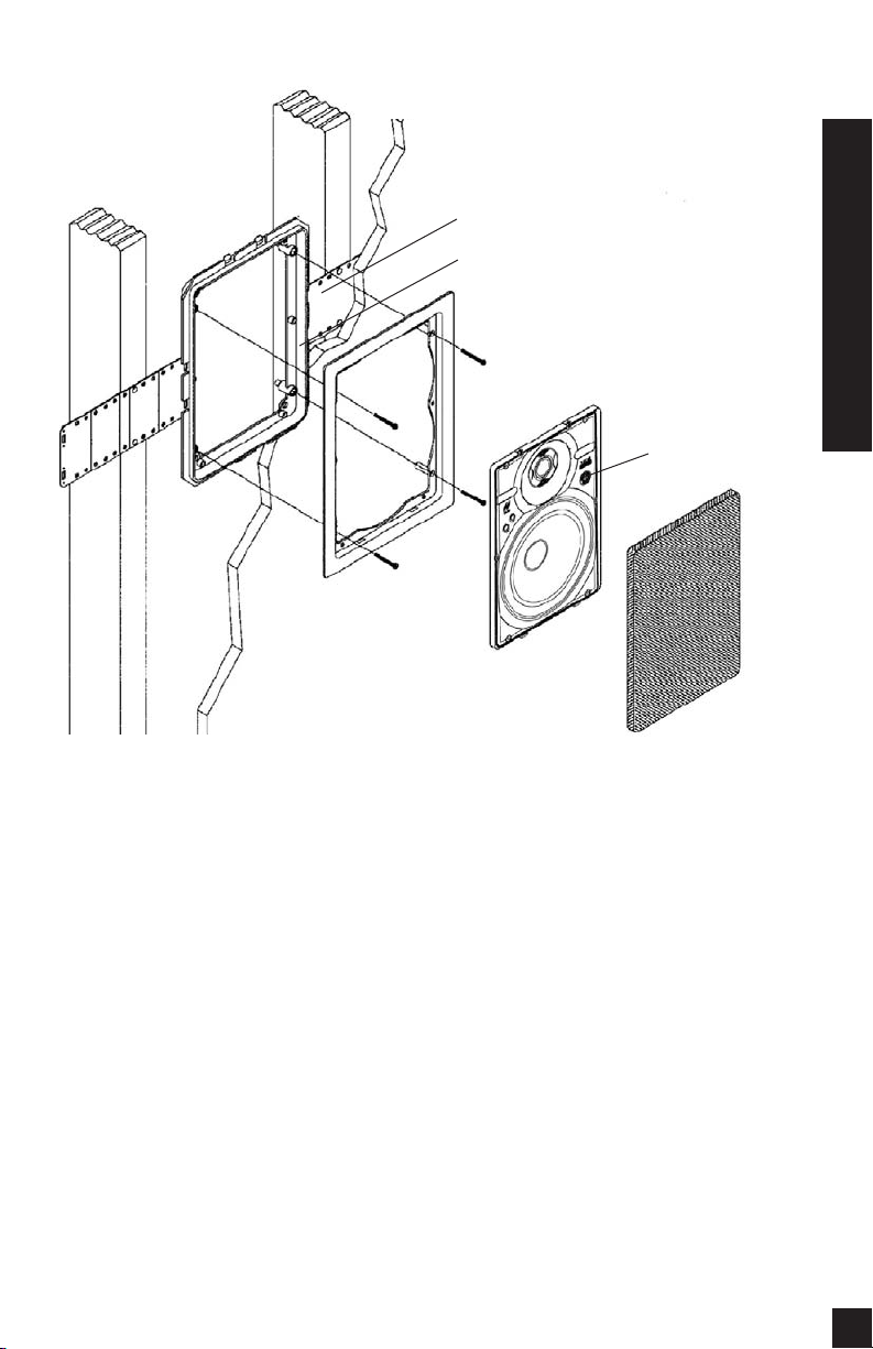
Model HD8 Shown
New Construction Wings
Bracket
Frame
Speaker Baffle
Figure 1
IR Knockout
Installation Considerations
Grille
Installation Considerations
Recommended Amplifier Power
For satisfactory performance, we recommend an amplifier with a power rating of
ten to one hundred watts for the HD5;
and ten to one hundred twenty-five watts
for the HD6, and ten to one hundred fifty
watts for the HD8 and HD8.3. Curiously,
most speakers are not damaged by large
amplifiers but by small amplifiers. If your
system is playing loudly, a small amplifier
will run out of power very quickly. When
an amplifier runs out of power it creates
damaging “clipping” distortion. A large
amplifier will play at the same volume
without distorting. See the section on
operating the speakers for more information about clipping distortion.
Incorporating a Local Volume Control
In a multiroom system there is one indispensible device for true convenience—a
local volume control. It allows you to
adjust the volume of the speakers without
leaving the room.
Plan to wire the system so that each pair
of speakers has its own volume control
built into the wall (think of a volume control as a dimmer switch for sound).
Niles makes a wide range of high performance indoor and outdoor volume controls. They are available in Standard or
Decora
light switches and dimmers).
trols are connected in line with the speak-
®
style cover plates (just like your
olume con
V
-
4
Page 6

Installation Considerations
er, so you must connect the wire from the
amplifier to the volume control and then
from the volume control to the speaker.
Speaker Wire
Use 2-conductor speaker wire when connecting HD speakers to your receiver or
amplifier. For most applications, we recommend you use 16 or 18 gauge stranded
wire. For wiring runs longer than 80 feet
we recommend 14 gauge stranded wire.
The no-strip terminals of the HD speakers
will accommodate 12 to 18 gauge wire.
When you run wire inside walls, special
jacketing (CL-2 or CL-3) is required to
both protect the wire and for fire prevention. In some areas conduit is required.
For a trouble-free installation, low voltage
wire such as speaker wire must be run in
accordance with the National Electrical
Code and any applicable provisions of the
local building code. If you are unsure of
the correct installation techniques, wire
jacket or type of conduit to use, consult a
professional audio/video installer, your
building contractor, or the local building
and inspection department.
Incorporating a Remote Control
If you are planning to use a stereo system
with a hand held IR remote control, consider the advantages of installing a Niles
IR Repeater system. You are able to control all of the functions of your system
from the room with the remote pair of
speakers. Niles makes a number of IR sensors which install in the wall, in the ceiling,
in cabinetry, on tabletops, or even behind
the grille of your Niles HD speakers.
An IR sensor requires that a 2-conductor
shielded wire (West Penn D291 or equivalent) be home run from each sensor location to the main equipment location. This
wire is normally run beside the speaker
wire at the same time. Typically, the sensor is placed in a location that faces your
listening position. Most remote controls
will have an effective line of sight range of
18 to 30 feet with any Niles sensor placed
in a wall, ceiling, on a cabinet or tabletop.
However, when you place a Niles MS110
MicroSensor
minum grille of a speaker the effective
range is reduced to 9 to 15 feet.
Insulating the Wall Cavity
For best performance from your speakers fill
the wall cavity behind the speaker with
fiberglass insulation (e.g. R-19 unbated insulation). Try to keep the same amount of
insulation for each speaker, particularly in
the same room, for consistent bass response.
®
behind the perforated alu-
TECH TIP
Wire size is expressed by its AWG (American Wire
a
G
h
t
umber. The lower the number, the larger
n
)
e
g
u
ire, i.e. twelve AWG is physically larger than
w
e
fourteen AWG.
5
Page 7
Speaker Placement
Placement for Critical Listening
If you like to imagine that the band or
orchestra is playing in front of you as you
listen to music, or you are very conscious of
clarity, detail and the textures of the individual instruments, you are a critical listener.
In a home theater, the intelligibility of dialog and action reproduced by the front
speakers is paramount! The position of the
speakers plays a very important role in
how clear the sound is and how a stereo
image is created. Here are some guidelines to make the process of placement
quick and easy.
Make sure the sound will not be blocked
or reflected off of furniture or other objects.
You should have a direct line of sight with
the front of the speaker. To determine the
best position, measure the “listening” distance between the ideal listening position
(your favorite chair or couch) and the wall
in which you plan to install the speakers.
Try to place the speakers so that they are
equally distant from your listening spot and
at least one half of the listening distance
apart (this maintains a large pleasant stereo
“image”). In home theater applications
where there is a center channel you may
choose to space the left and right main
speakers farther apart for a “bigger than
life” sound with Dolby
®
encoded movies
and TV shows. However, for combined
music and movie usage stay within the
good placement zone for music. For example; if you are ten feet back from the wall,
the speakers should be between five and
ten feet apart
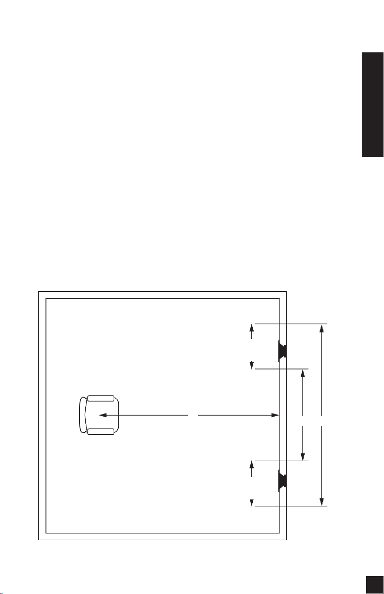
(See Figure 2).
Speaker Placement
Figure 2
Speaker
Placement
Zone
10 ’
Speaker
Placement
Zone
5’
10 ’
6
Page 8

Speaker Placement
The Boundary Effect
Corners can affect the bass response of
the speaker powerfully! This is called the
boundary effect. You will emphasize particular bass frequencies and cancel out
other bass frequencies when you place
speakers close to the wall/ceiling boundary or a corner wall boundary. This can
make the speaker sound excessively
boomy and inaccurate to some listeners,
while to others it just seems like more
bass sound. A good rule of thumb is if
you always listen to your current pair of
speakers with the bass turned up, you’ll
enjoy corner placement. If you keep your
tone controls at neutral, try to keep the
speakers at least two or three feet from
the boundaries of the room.
Placement for Varying Listening
Positions
If you want the freedom to sit anywhere
in a room facing any direction, and/or
find that you prefer the “all around you”
sound of some car stereos to a conventional “sound stage” facing you, consider
the speaker placement techniques professional installers use in restaurants and
bars. They place speakers in an array
around the listening area, so that the
music is always surrounding you, regardless of the direction you face.
The rule of thumb is to add one pair of
speakers for every 100 to 200 square feet
of listening area. Curiously, this is not so
that you can play the music louder, but
so that you can play it softer! When you
have only one pair of speakers in a large
room you will notice that when the
sound is perfect in one part of the room,
it is too loud near the speakers. By placing more than one pair in the room you
will avoid these “hot spots” of loud
sound and you will create more sonic
ambiance while maintaining clarity and a
rich sound everywhere.
You can make listener position still less
critical by using mono rather than stereo.
This can be difficult to achieve with normal stereo amplifiers. However, Niles
manufactures Systems Integration
Amplifiers which enable one room to be
wired in stereo while other rooms are
wired in mono! Consult your local Niles
dealer for more information.
In smaller rooms or rooms that are infrequently used, you typically can’t justify
the expense of more than two speakers.
Try to bracket the room with the two
speakers. Diagonal placement is a very
effective way to stretch the coverage pattern of two speakers. You can also compromise between direct sound (for detail
and clarity) and reflected sound (the
ambient or “all around you” effect). By
trying to place the speakers so that they
create as much reflected sound as possible you emphasize the ambient effect.
They can be up high in the wall or even
down low at power outlet height , in the
ceiling, near corners, or directed at
reflective objects and walls. The more
reflected sound there is in the room the
stronger the ambient effect at low volumes. You should use moderation, however, otherwise the compromise becomes
too one sided and at high volumes, the
sound will be blurred and less distinct.
Placement for Home Theater Rear
Applications
In a home theater, the goal is to reproduce the experience of a great movie theater in our homes. The biggest difference
between the two is the rear or surround
speaker array in a commercial theater.
Here, it is not uncommon to see twenty
or thirty speakers around the audience.
This huge array of speakers assures that
you will feel completely surrounded by
the ambient soundtrack of the movie.
Film makers try to use the “surround”
7
Page 9

soundtrack to envelope you in the environment on screen. They will place background music, rain sounds, traffic noise,
etc. on the “surround” soundtrack. In a
home with a single pair of speakers it is
easy for the jungle sounds to sound like
they are “in the middle of your head” just
like headphones!
A single pair of HD Loudspeakers, properly placed, can create a very convincing
simulation of an array of speakers. If you
place them near a hard reflecting surface
you can make one pair of speakers sound
like several. Create as many reflections as
possible by mounting the speaker up high
in the wall so that the ceiling will act as a
powerful reflector. If you place the speakers near a corner, wash the sound down a
wall from a ceiling location, or mount the
speakers as far away as you can from the
listening area, more reflections will occur.
However, all of these placement techniques require that you work your surround sound amplifier channels harder. If
the surround sound system you are using
has a small five or ten watt amplifier for
the rear speakers, stay within five to eight
feet of the listening location. If you are
using a 25 to 50 watt amplifier you can
mount the speakers 10 to 15 feet away
from the listening location and still
achieve reasonably high volume levels.
Of course, the best way to emulate the
sound of multiple speakers is to use multiple speakers. In large or unusually shaped
rooms this might be the only way to
achieve a good effect. If you like to listen
to music surround modes which emulate
concert hall acoustics, more than two surround speakers will prove extraordinarily
effective. With Niles HD loudspeakers it is
easy to add another pair without affecting
the decor of the room. However, you will
need to use a much more powerful amplifier than that which is built into a typical
surround sound receiver or amplifier. Niles
makes a number of Systems Integration
Amplifiers
make them uniquely suited to enhance a
good surround sound system. Consult your
local Niles dealer for more information.
®
with proprietary features that
Speaker Placement
8
Page 10

Installation Fundamentals
Installation
Fundamentals
Running the Speaker Wire in New
Construction
If you have doubts about whether you are
capable of installing a Niles HD loudspeaker in your walls, consult a Niles
dealer or professional installer. They have
special tools, techniques, and experience
to make the impossible possible. The
installer can provide you with an estimate
before any work is done.
Scheduling and Preparation
Plan to schedule the speaker wiring after
the electrical wiring is finished. That way
you can avoid wire routes which could
potentially induce hum over the speaker
wire. The basic rules are:
• Never run speaker wire through the
same hole as an electrical cable.
• Never run speaker wire into the same
J-box as electrical cable.
• Avoid running the speaker wire beside
the electrical cable. Keep your speaker
cable at a distance of at least 18"-22" from
Figure 3
any electrical power cable.
Side-by-side wiring is unavoidable in particular spots in every house, just move the
speaker wire route away as soon as possible. If construction forces a side by side
run for more than ten feet, install metal
conduit or shielded speaker wire. Lowvoltage wires such as doorbells, intercoms, telephone, security, or television
cannot cause interference or hum on your
speaker wires, so you can safely run all of
them at the same time, through the same
holes, side-by-side.
Before you drill any holes, mount the
speaker brackets in the desired speaker
locations and mount p-rings or open
backed J-boxes where the in-wall volume
controls and stereo equipment will be.
Safety First!
Wear gloves, safety goggles and head protection when drilling. Avoid nails, they ruin
bits and they can create injury. Pay particular care when using “hole-hogs” and other
powerful electric drills; the torque of the
drill when suddenly stopped by a nail can
break the wrist of a strong man.
Drilling
Use a bit that is large enough for the wires
you plan to run. An auger bit is the preferred bit for rough-in wiring. It will actually pull itself through the wood, so that
the drill motor, not you, does most of the
work. You may be drilling a lot of holes,
so this is an important consideration.
Always drill the holes in the center of the
stud. If you have to notch the stud or drill
the hole closer than one inch from the
edge of the stud, protect the wire with a
nail plate
When drilling holes in ceiling joists drill
in the center of the joists and try to locate
the hole near the end of the joist.
NOT drill through a “gluelam” or any
load bearing beam without the direction
(See Figure 3).
DO
9
Page 11

of your contractor.
Try to line the holes up perfectly, because
it makes pulling the wire much easier. A
good technique is to snap a chalk line
across the face of the studs or against the
bottom of the ceiling joists. Then work
backward so that you can always see the
holes you have already drilled. Paying
careful attention to this will save you a lot
of time later on!
Pulling the Cable
Pull the cable in sections (from the stereo
to the volume control, from the volume
control to the speaker). Start with the
longest sections and use left over wire to
complete the short sections. If you plan to
pull many rooms at the same time
through a central route, walk off the distance to each destination, add a generous
fudge factor for turns and other obstacles,
then cut off each section so that you have
a bundle of wires you can pull at once.
Whenever you run the wire further than
four and one half feet from a hole in a stud
or joist (open attic space, going up walls,
etc.), fasten the wire to the joists or studs
using cable clamps or appropriately sized
wire staples. The wire should not have
large sags in it, nor should it be too tight.
Try to protect the wire from being stepped
on in attics or other unfinished crawl
spaces. There are guard strips, raceways
and conduits which can be used to protect
the cable. Consult the local building code
for special requirements in your area.
Concealing Speaker Wire
in Existing Walls
This is actually a fairly simple task if you
restrict your choice of speaker locations
and wire routes to the interior walls or
ceilings of your home. Interior walls in
almost all North American residences are
hollow, so that it is easy to flush mount
speakers into them and route new speaker
cable around the house. What you see
when you look at the painted wall
board, plaster, or paneling is only the
skin of the wall. Behind the skin is the
skeleton; two-by-four wood or metal
“studs” running vertically from the floor
to the ceiling in walls and two-by-six or
larger “joists” running horizontally in the
ceilings and floors. In between the studs
and the joists is the space for the wiring
and plumbing of your home.
Exterior walls are different. They must
insulate the house from the heat and cold
outside, so they are stuffed with insulation.
The national building code requires that
the hollow wall space in exterior walls be
broken by a horizontal stud placed
between the vertical studs. This “fire
blocking” makes it very difficult to retrofit
long lengths of wire. In some areas of the
country the exterior walls are constructed
of solid masonry, and have no hollow
space for speakers or wires.
Start by examining all the possible routes
you might take to run the speaker wire
from the speaker to the volume control
and back to the stereo. Use a stud sensor
or other device to locate the internal
structure of the wall. You want to avoid
all studs or joists. A typical route would
be: from the speaker location up the
inside of the wall to a new hole drilled
into the top “plate” (horizontal two-byfour at the top of the inside of the wall),
into the attic crawl space, then down to
the volume control location through
another top plate, back up to the attic,
across the attic, and finally down another plate to the wall behind the stereo system itself
common route is through the bottom
plate of the wall into an unfinished basement or crawl space.
(See Figure 4). The other very
Installation Fundamentals
10
Page 12

Installation Fundamentals
Speaker
Location
Identify where all of your electrical,
phone, and TV wiring is likely to be and
plan to route around it all. You can accidentally induce 60 Hz hum on your
speakers if you run your speaker wire right
beside electrical wire for more than a few
feet. Try to keep speaker wire running parallel to power cables at least 3 feet away.
To find exactly where an electrical cable is
routed, try inspecting the inside of the wall
by turning off the breaker for a particular
power outlet or switch, remov
Volume
Control
Location
Figure 4
Stereo
Location
ing the
If your house is built on a slab or you are
wiring between two finished floors, look
for baseboards which could be removed
and replaced with the wire behind them.
Doorjambs can be removed and often
have enough space for speaker wire all
the way around the door
Sometimes, an under-the-carpet run is
possible (there are special flat speaker
wires made for under-the-rug wire runs).
As a last resort, heating and air conditioning vents can be used as wire raceways for
cover plate and switch or
receptacle, and shining a penlight into the wall. If you have
access to an attic or basement
space you can quickly see
which part of the wall space is
free of obstructions
Figure 5)
When you don’t have access
above or below the wall, try
to estimate the existing wire
and pipe locations from the
positions of electrical outlets
and plumbed fixtures on both
sides of the wall. Take a look
at the outside of your house
too, sometimes conduit, vents
or drain pipe will be visible
that give useful information.
Choose the route with the
fewest potential obstacles.
.
(See Figure 6).
(See
11
Unobstructed space
for speaker wiring
Figure 5
Page 13

plenum rated wire (check your local
building codes, some municipalities
require conduit).
In traditional wood stud/drywall construction you can cut the hole for the speaker
and utilize the large hole to auger holes
across, up or down the wall for as far as
your drill bit will take you. If you have
matching paint and take reasonable care in
patching you can cut a hatch in the drywall at each stud, run your wire, and patch
and touch-up the wall
When you are dealing with the unknown
because of the structure of your home, or
with difficult to patch wall materials like
plaster, lath and plaster, faux finishes,
wallpaper etc., be patient. A careful study
of the potential problems before you start
the job will pay off.
(See Figure7).
Figure 7
Figure 6
Installation Fundamentals
12
Page 14

Installation of Brackets, Frames and Grilles in New Construction
Installation of
Brackets, Frames
and Grilles in New
Construction
Stage One: Before Drywall is Hung.
Insulating the Wall Cavity.
If feasible, fill the wall cavity with insulation at this point.
Attach the wings to the bracket by snapping them into the sides of the bracket.
The wings can be shortened by breaking
them along the scored lines if their length
will interfere with a corner or eaves. You
can mount the bracket horizontally or ver-
(See Figure 8).
tically
Screw one side of the assembled bracket
with wings to the stud using one of the
supplied screws. Level the bracket. Screw
the other side of the bracket to the stud.
Two or three screws (depending upon the
size of the model) on each side makes for
a very secure installation. Attach the wire
to the bracket at the indicated wire tie
points
(See Figure 9).
Stage Two: Before Paint
Screw the frame to the installed bracket
using the supplied screws. Do not overtighten the screws. This will distort the
frame and the grilles will not fit (this is not
permanent, just loosen the screws and the
grille will pop in)
Painting the Aluminum Grilles
The grille is important to the sound of the
(See Figure 10).
13
Figure 8
Page 15

Figure 9
Figure 10
HD loudspeakers. Do not fill the holes of
the grille with paint. The grille is constructed of aluminum with a perfectly even
powder coat overall. This powder coat is
an ideal primer.
Remove the grilles before painting. If you are
using spray paint, use two thin coats without
any primer. If you are using a compressor and
a spray gun, use the finest, most diffuse
setting. Practice first on some paper if you
have no experience painting with spray paint.
If you are using an applicator or brush, and
a can of paint, thin the paint first. You do
not want to have to poke hundreds of
holes in your beautifully painted grilles.
Installation of Brackets, Frames and Grilles in New Construction
14
Page 16

Installation of Brackets, Frames and Grilles in Existing Walls
Figure 11
Installation of
Brackets, Frames
and Grilles in
Existing Walls
IMPORTANT: Before you cut into any
wall, review the sections on running
wire and speaker placement.
1. Drill a 1/8” pilot hole just barely
through the wallboard or dry wall (1/2” to
5/8” deep in most homes) about an inch
below the center of your proposed speaker location (an inch to the side if you are
mounting the speaker horizontally). BE
VERY CAREFUL NOT TO DRILL
THROUGH EXISTING WIRES, PIPES, OR
STRUCTURE. IF YOU FEEL ANY EXTRA
RESISTANCE AS YOU ARE DRILLING,
STOP. Cut a piece of coat hanger equal to
the width of the bracket. Bend the wire in
half creating a right angle. Poke the “Lshaped” wire into the pilot hole and turn it
Figure 12
in a complete circle. If it turns freely,
repeat the procedure from a hole about an
inch above the center of your proposed
speaker location
If the wires movement is obstructed by a
pipe or cable, fill the hole (s) with spackle
or other patching compound and try
another location.
2. When determining the final location of
the cutout keep in mind that the frame
and bracket will extend beyond the
cutout. Make sure that you do not place
the edge of the cutout directly next to a
stud. Locate the studs using a stud sensor
or hand-knocking. Once you have determined the correct position for the cutout,
hold the supplied template up to the wall
surface. Level the template in either the
horizontal or the vertical position and
(See Figure 11).
mark the wall with a pencil.
Drill the four corners with a
1/4” drill bit.
3. If you are cutting a painted
or wall papered drywall use
a sheetrock or keyhole saw.
Cut the hole with the saw at
a 45 degree angle. That way,
the drywall section can be
15
Page 17

replaced cleanly if there is an unseen
obstruction behind the wall. BE VERY
CAREFUL NOT TO SAW THROUGH
EXISTING WIRES, PIPES, OR STRUCTURE.
IF YOU FEEL ANY EXTRA RESISTANCE AS
YOU ARE CUTTING, STOP.
4. If you are cutting into lath and plaster
walls, use masking tape to outline your
penciled marks, drill the four corners with
a 1/4” bit and use a razor to score the
plaster down to the lath beneath. Then use
a chisel to remove all of the plaster within
the taped outline. Finally, insert a metal
cutting blade into a sabre saw and very
slowly and carefully saw the lath. Sawing
the lath can easily vibrate plaster off the
wall. If you have the patience, use a pair
of tin snips to slowly nip away at the lath
instead. There is no risk with this method,
it is just time consuming.
5. Fill the wall cavity with insulation at
this point. Remember to use equal
amounts of insulation for each speaker.
6. Slip the mounting bracket through the
hole and pull it toward you so that its front
edge slides into the hole and stops in place.
7. Attach the frame to the bracket by
screwing the frame to the bracket using
the supplied screws. Do not overtighten
the screws, this will distort the frame and
the grilles will not fit (this is not permanent, just loosen the screws and the grille
will pop in). The screws should pull the
frame and bracket together (sandwiching
the drywall) so that the frame is absolutely
flush with the wall surface. There should
be no gaps between the wall and the
(See Figure 12).
frame
Installation of the Speaker, Sensor and Grille in New or Existing Construction
Installation of the
Speaker, Sensor and
Grille in New or
Existing Construction
Installing a Niles MS110 MicroSensor
There is a 1/2" round molded "IR Sensor
Knockout" on the face of the speaker baffle. To prevent damage to the crossover
network you must remove the knockout
from the rear of the speaker. Do not
attempt to remove the knockout with the
speaker face up. Lay the speaker face
down on a clean carpet or rug. Put the tip
of a screwdriver into the center of the
round "knockout" and sharply tap the
screwdriver handle as necessary. Install
the MS110 using its mounting hex nut and
washer so that it is tightly secured to the
speaker. Connect all wires and continue
your installation.
16
Page 18

Installation of the Speaker and Grille in New or Existing Construction
Installing the Speaker
If the grille is already
installed, remove it by using
a bent paper clip or the tip
of a corkscrew and pulling
it away from the frame
(See Figure 13).
1. Separate the speaker wire so
that at least two inches of each
conductor are free.
2. Strip 1/2" of insulation from the end of
each conductor. (See Figure 1.)
Figure 13
enclosed sheet metal screws to secure
the baffle to the frame.
a. Locate the dimples on the front baffle.
b. Place the self-tapping sheet metal
screw in the dimple and turn it with a
screw driver until it cuts through the
baffle and anchors securely in the
frame
pushing the speaker for-
ward until the s n a p s
(See Figure 16).
engage
8.
IMPORTANT:
When installing the
speakers in the ceiling, or
if the installation is in an
earthquake zone, it is recom-
mended that you utilize the
(See Figure 17).
Figure 1
3. To connect the stripped end of one conductor to the black terminal, push down
on the black terminal lever. Insert
the stripped end of the conductor into
the opening. Release the pressure on
the lever.
17
4. Repeat #3 with the other conductor and
the red terminal.
5. Connect the opposite ends of these conductors to their respective amplifier terminals. Pay attention to the markings on
the wire. If you are unsure which conductor to insert into which terminal, see
the section titled “Speaker Phase” in the
owner’s manual.
6. Repeat these instructions for each speaker you are connecting to the amplifier.
7. Place the speaker baffle in the frame
by inserting the tabs at the base of
the speaker baffle into the corre
sponding holes in the frame and
Figure 16
Page 19
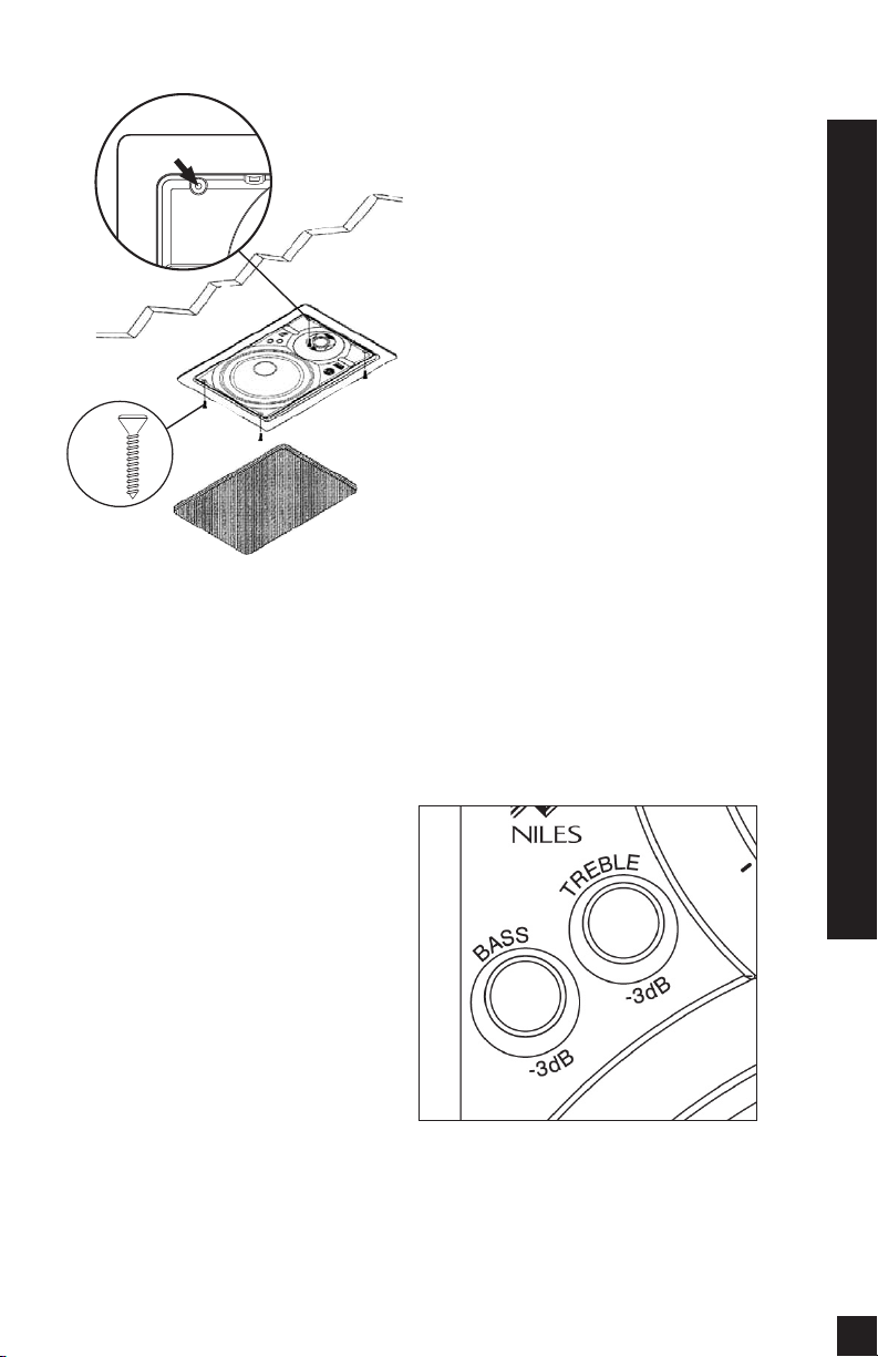
Figure 17
Speaker Phase
Speaker wire has two conductors. One
conductor is attached to the negative (-)
terminals and one conductor is attached to
the positive (+) terminals of both your
speaker and your amplifier. Usually, the
wire is marked for your convenience.
There are different ways wires are marked:
a stripe on one wire, a ribbed area of one
conductor you can only feel, different colors of metal wire on each conductor, or
there might be a fabric strand or string
wound into one of the conductors. Of
course, there are some wires which appear
completely identical. Be careful, or you
might make a mistake.
If you make a mistake, one speaker will be
playing “out-of-phase” with the other
speaker. An out-of-phase pair of speakers
work against each other and the sound of
the two speakers playing together will be
lacking in bass and be “phasey” sounding.
If you suspect the sound is not right and
you cannot see any markings on the wire,
try this simple test:
1. Stand half way between the two speakers.
2. Play some music with the amplifier or
radio set to Mono.
3. Listen to the richness of the bass and the
loudness of the sound.
4. Turn off the amplifier and reverse the connections on one amplifier channel only.
5. Repeat the listening test with the same
setting of the volume control. When the
sound has a richer bass and is slightly
louder the speakers are working together
or “in-phase”.
Adjusting the Bass and Treble
Controls
The HD High Definition loudspeakers
feature separate baffle-mounted bass and
treble controls for fine tuning after installation. Each control provides for approximately 3dB in steps of 1dB of Bass or
Treble reduction. This is useful if the
speakers are placed near boundaries (Bass
Cut) or in a room with highly reflective
surfaces like glass or tile. (Treble Cut).
(See Figure 18).
Figure 18
Installation of the Speaker and Grille in New or Existing Construction
18
Page 20
Installation of the Speaker and Grille in New or Existing Construction
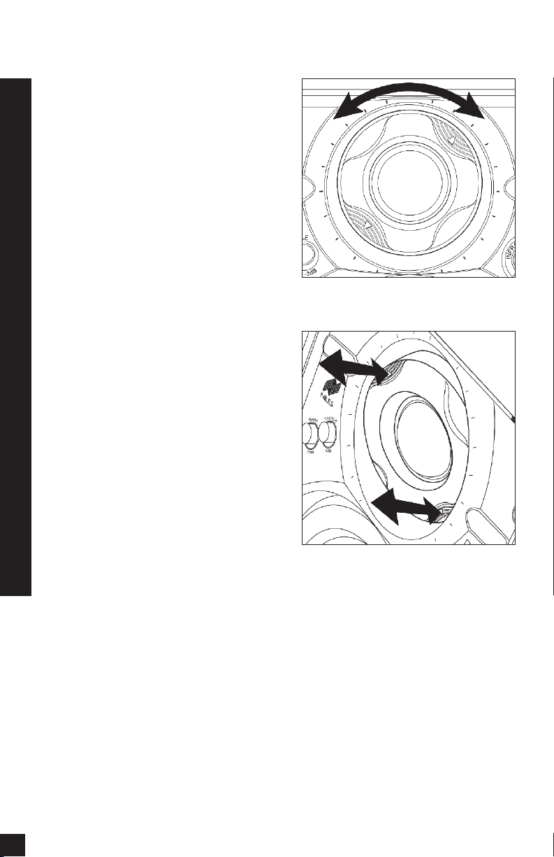
Adjusting the Tweeter
The tweeter is housed in a precision adjustment mechanism which enables precise
aiming of the directional high frequencies to
provide optimum performance. To adjust
the tweeter:
1. Carefully grasp the tweeter housing by
placing your thumb and forefinger in the
indentations provided.
2. Rotate the tweeter housing either clockwise or counter clockwise as required.
The mechanism is indexed at equal
intervals so that both speakers in a pair
can be adjusted equally. Simply count
the number of “clicks” as the first tweeter is adjusted. Repeat the process for the
second speaker, rotating the tweeter the
same number of “clicks” in the opposite
direction
3. Pivot the tweeter on both speakers
equally by depressing the housing at the
arrows until the desired angle is
achieved
Installing the Grille
Carefully fit the grille into its recess so that it
is barely in place. Starting with one corner,
go around the speaker, pushing the grille in
a little bit each time. You should be gentle,
the aluminum grille can be easily bent out
of shape. The speaker will have an absolutely flush appearance when it is properly
installed.
(See Figure 19).
(See Figure 20).
Figure 19
Figure 20
19
Page 21
Operation
I
N
F
R
A
R
E
D
S
E
N
S
O
R
K
N
O
C
K
O
U
T
1
-8
00-BUY-HIFI
1
-
8
0
0
-
2
8
9
-
4
4
3
4
w
w
w
.
n
i
l
e
s
a
u
d
i
o
.
c
o
m
1-800-B
UY-H
IFI
1
-
8
0
0
-
2
8
9
-
443
4
w
w
w
.
n
i
l
e
s
a
u
d
i
o
.
co
m
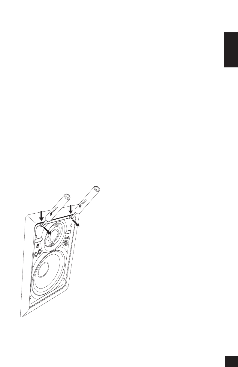
Removal of Speaker
and Grille
Removing The Speaker
If the grille is already installed, remove it by
using a bent paper clip or the tip of a
corkscrew and pulling it away from the frame.
Utilizing two small screwdrivers or two
needle nose pliers, release the snaps that
hold the speaker to the frame. Insert the
screwdrivers into the holes in the snaps
and exert force straight down (towards the
woofer) until the snaps release. Once the
snaps release, the speaker can be tilted
away from the frame to be removed. Do
not attempt to use the frame for leverage,
as this may damage the surface of the
(See Figure 21).
frame
Operation
Listening at Higher Volumes
It requires more power to achieve a reasonable volume of sound in a large room than
it does in a small room. It is possible (even if
you are not a teenager) to turn the volume
so high that the amplifier
This creates “clipping” distortion.
Clipping distortion makes treble sound
very harsh and unmusical. When you hear
harsh sounding treble from any good
speaker, turn the volume down immediately! Those harsh sounds are masking
some much more powerful ultra-high-frequency sound spikes which will quickly
damage any fine loudspeaker. You are
much less likely to damage a speaker with
a large amplifier because it will be very
loud indeed before it produces any clipping distortion.
Cleaning
You can clean the speaker with a dampened soft cloth or paper towel. If the
speaker is mounted high up on a wall or
ceiling, use a broom to gently brush it off.
runs out of power.
Figure 21
20
Page 22

Specifications
Specifications
Model HD5
Model HD6
Driver Compliment
5-1/4” Injection-Molded TCC Woofer with
Custom Debris Screen, Butyl Rubber
Surround, High BL Magnet Structure with
Vented Pole Piece
1” Teteron Tweeter Housed in a Low
Diffraction Precision Adjustment
Mechanism
Design Principle
Infinite baffle for large and varying air
volumes
Recommended Amplifier Power
Ten to One Hundred Watts per Channel
Nominal Impedance
6 Ohms
Frequency Response
60 Hz to 21,000 Hz, plus or minus 3dB
(on axis)
Dispersion Pattern
90 degrees Horizontally or Vertically
(plus or minus 5dB)
Sensitivity
88 decibels for 2.83 volts of Pink Noise,
measured at 1 meter on axis
Overall Exterior Frame Dimensions
7-1/8” x 9-7/8” (18.1 cm x 25.1 cm)
Depth Behind Wall
3-1/8” Deep (assumes 1/2” drywall)
(7.9 cm)
Wall Cut-Out Dimensions
6-1/4” x 9” (15.9 cm x 22.9 cm)
Wiring Requirements
We recommend 16 to 18 gauge stranded
wire for up to 80 feet, 14 gauge stranded
wire for up to two hundred feet.
Connectors accommodate 12 to 18 gauge
stranded wire.
Driver Compliment
6-1/2” Injection-Molded TCC Woofer with
Custom Debris Screen, Butyl Rubber
Surround, High BL Magnet Structure with
Vented Pole Piece
1” Teteron Tweeter Housed in a Low
Diffraction Precision Adjustment
Mechanism
Design Principle
Infinite baffle for large and varying air
volumes
Recommended Amplifier Power
Ten to One Hundred Twenty Five Watts
per Channel
Nominal Impedance
6 Ohms
Frequency Response
50 Hz to 21,000 Hz, plus or minus 3dB
(on axis)
Dispersion Pattern
90 degrees Horizontally or Vertically
(plus or minus 5dB)
Sensitivity
89 decibels for 2.83 volts of Pink Noise,
measured at 1 meter on axis
Overall Exterior Frame Dimensions
8-3/4” x 11-11/16” (22.2 cm x 29.7 cm)
Depth Behind Wall
3-1/8” Deep (assumes 1/2” drywall)
(7.9 cm)
Wall Cut-Out Dimensions
7-5/8” x 10-5/8” (19.4 cm x 27 cm)
Wiring Requirements
We recommend 16 to 18 gauge stranded
wire for up to 80 feet, 14 gauge stranded
wire for up to two hundred feet.
Connectors accommodate 12 to 18 gauge
stranded wire.
21
Page 23

Specifications
Specifications
Model HD8
Driver Compliment
8” Injection-Molded TCC Woofer with
Custom Debris Screen, Butyl Rubber
Surround, High BL Magnet Structure with
Vented Pole Piece
1” Teteron Tweeter Housed in a Low
Diffraction Precision Adjustment
Mechanism
Design Principle
Infinite baffle for large and varying air
volumes
Recommended Amplifier Power
Ten to One Hundred Fifty Watts per
Channel
Nominal Impedance
6 Ohms
Frequency Response
40 Hz to 21,000 Hz, plus or minus 3dB
(on axis)
Dispersion Pattern
90 degrees Horizontally or Vertically
(plus or minus 5dB)
Sensitivity
90 decibels for 2.83 volts of Pink Noise,
measured at 1 meter on axis
Overall Exterior Frame Dimensions
10-3/16” x 14-1/4” (25.9 cm x 36.2 cm)
Depth Behind Wall
3-1/8” Deep (assumes 1/2” drywall)
7.9 cm
Wall Cut-Out Dimensions
9-1/8” x 13-1/8” (23.2 cm x 33.3 cm)
Wiring Requirements
We recommend 16 to 18 gauge stranded
4 gauge stranded
wire for up to 80 feet,
wire for up to two hundred feet.
Connectors accommodate 12 to 18 gauge
stranded wire.
1
Model HD8.3
Driver Compliment
8” Injection-Molded TCC Dual Drive
Woofer with Hyperbolic Dispersion
Stabilizer, Custom Debris Screen, Butyl
Rubber Surround, High BL Magnet
Structure with Vented Pole Piece
1” Teteron Tweeter Housed in a Low
Diffraction Precision Adjustment
Mechanism
Design Principle
Infinite baffle for large and varying air
volumes
Recommended Amplifier Power
Ten to One Hundred Fifty Watts per
Channel
Nominal Impedance
4 Ohms
Frequency Response
40 Hz to 21,000 Hz, plus or minus 3dB
(on axis)
Dispersion Pattern
90 degrees Horizontally or Vertically
(plus or minus 5dB)
Sensitivity
91 decibels for 2.83 volts of Pink Noise,
measured at 1 meter on axis
Overall Exterior Frame Dimensions
10-3/16” x 14-1/4” (25.9 cm x 36.2 cm)
Depth Behind Wall
3-1/8” Deep (assumes 1/2” drywall)
(7.9 cm)
Wall Cut-Out Dimensions
9-1/8” x 13-1/8” (23.2 cm x 33.3 cm)
Wiring Requirements
18 gauge stranded
6 to
We recommend
wire for up to 80 feet, 14 gauge stranded
wire for up to two hundred feet.
Connectors accommodate 12 to 18 gauge
stranded wire.
1
22
Page 24

Notes
Notes
________________________________
________________________________
________________________________
________________________________
________________________________
________________________________
________________________________
________________________________
________________________________
________________________________
23
________________________________
________________________________
________________________________
________________________________
________________________________
________________________________
________________________________
Page 25

Notes
________________________________
________________________________
________________________________
________________________________
________________________________
________________________________
________________________________
________________________________
________________________________
Notes
________________________________
________________________________
________________________________
________________________________
________________________________
________________________________
________________________________
________________________________
24
Page 26

Notes
Notes
________________________________
________________________________
________________________________
________________________________
________________________________
________________________________
________________________________
________________________________
________________________________
________________________________
25
________________________________
________________________________
________________________________
________________________________
________________________________
________________________________
________________________________
Page 27

Notes
________________________________
________________________________
________________________________
________________________________
________________________________
________________________________
________________________________
________________________________
________________________________
________________________________
Notes
________________________________
________________________________
________________________________
________________________________
________________________________
________________________________
________________________________
26
Page 28

Niles Audio Corporation
12331 S.W. 130 Street
Miami, Florida 33186
73
el: (305) 238-4
T
3
Fax: (305) 238-0185
www.nilesaudio.com
©2008 Niles Audio Corporation. Patents applied for and pending. DS00282B
 Loading...