

Page 1
Niles Audio Corporation
www.nilesaudio.com
12331 S.W. 130 Street
Miami, Florida 33186
Tel: (305) 238-4373
Fax: (305) 238-0185
©2003 Niles Audio Corporation. All Rights Reserved. Niles, the Niles logo, IntelliPad, Blending High Fidelity and
Architecture are registered trademarks of Niles Audio Corporation. All other trademarks are the property of their
respective owners. Because we constantly strive to improve our products, Niles reserves the right to change
product specifications without notice. The technical and other information contained herein is not intended to
set forth all technical and other specifications of Niles products. Additional information can be obtained on-line
at www.nilesaudio.com or by calling Niles at 1-800-289-4434. Printed in USA. 11/03 DS 00364A
Doorbell Interface
B
LENDING H IGH F IDELITY AND A RCHITECTURE
®
INSTALLATION & OPERATION GUIDE
DBI-1
DBI-1
Page 2

D OORBELL I NTERFACE
3
TABLE OF CONTENTS
INTRODUCTION ............................................................................................3
FEATURES AND BENEFITS............................................................................3
PARTS GUIDE ................................................................................................4
DESCRIPTION ................................................................................................4
OPERATION OVERVIEW ..............................................................................6
INSTALLATION CONSIDERATIONS..............................................................6
INSTALLATION ..............................................................................................7
Mounting the DBI-1 ....................................................................................7
Connecting the DBI-1 ..................................................................................7
INSTALLATION SETTINGS ..........................................................................10
Contact Closure Triggers ............................................................................10
3V-30V Voltage Triggers ............................................................................10
Chime and Audio Level Adjustments..........................................................10
Setting the Tone/Delay ..............................................................................10
Recommended Tone/Delay Settings ..........................................................11
Identifying the Version of a Niles MultiZone System..................................11
Chime Selection..........................................................................................11
Recording a Custom Chime ......................................................................12
Recording an Active Audio Signal ........................................................12
Recording a Paused Audio Signal..........................................................13
SPECIFICATIONS..........................................................................................14
D OORBELL I NTERFACE
2
INTRODUCTION
The DBI-1 Doorbell Interface provides realistic doorbell chimes throughout a home installed with
a Niles MultiZone System. External contact closure and voltage triggers (for both a front and rear
door) are combined with a programmable trigger tone/delay to integrate with all Niles
MultiZone Control Systems.
The DBI-1 includes a choice of four pre-recorded and one recordable custom chime to provide
the appropriate doorbell chime for any home. A UL-listed, universal voltage power supply is
included for convenience.
FEATURES AND BENEFITS
•
Provides doorbell chimes to Niles MultiZone controllers
•
Four selectable preprogrammed chimes and one user recorded
sound option
•
Two doorbell inputs, front and rear, triggered by voltage and
contact closure via screwless two piece connector
•
Separate level adjustments provided for chime and page pass through
•
One gold-plated mono audio sensing input
•
One gold-plated mono audio output
•
Features UL-listed regulated in-line power supply with universal
voltage capability
•
Warranty: Two-year limited
Page 3
D OORBELL I NTERFACE
5
D OORBELL I NTERFACE
4
PARTS GUIDE
The DBI-1 package includes the following parts:
• One (1) DBI-1 Doorbell Interface
• One (1) Set of Rubber Feet
• One (1) Universal Voltage Power Suply
• One (1) Installation & Operation Guide
• One (1) Warranty Card
After unpacking and before installation, the installer should carefully inspect the contents. If any
damage is discovered due to shipping, the installer should contact Niles Audio for assistance (see
back cover or Warranty Card for contact information). Also, keep all packing materials in case the
product ever needs to be returned to the factory.
DESCRIPTION (Continued)
a
b
c
e
a
d
g
f
h
i
j
k
l
m
n
o
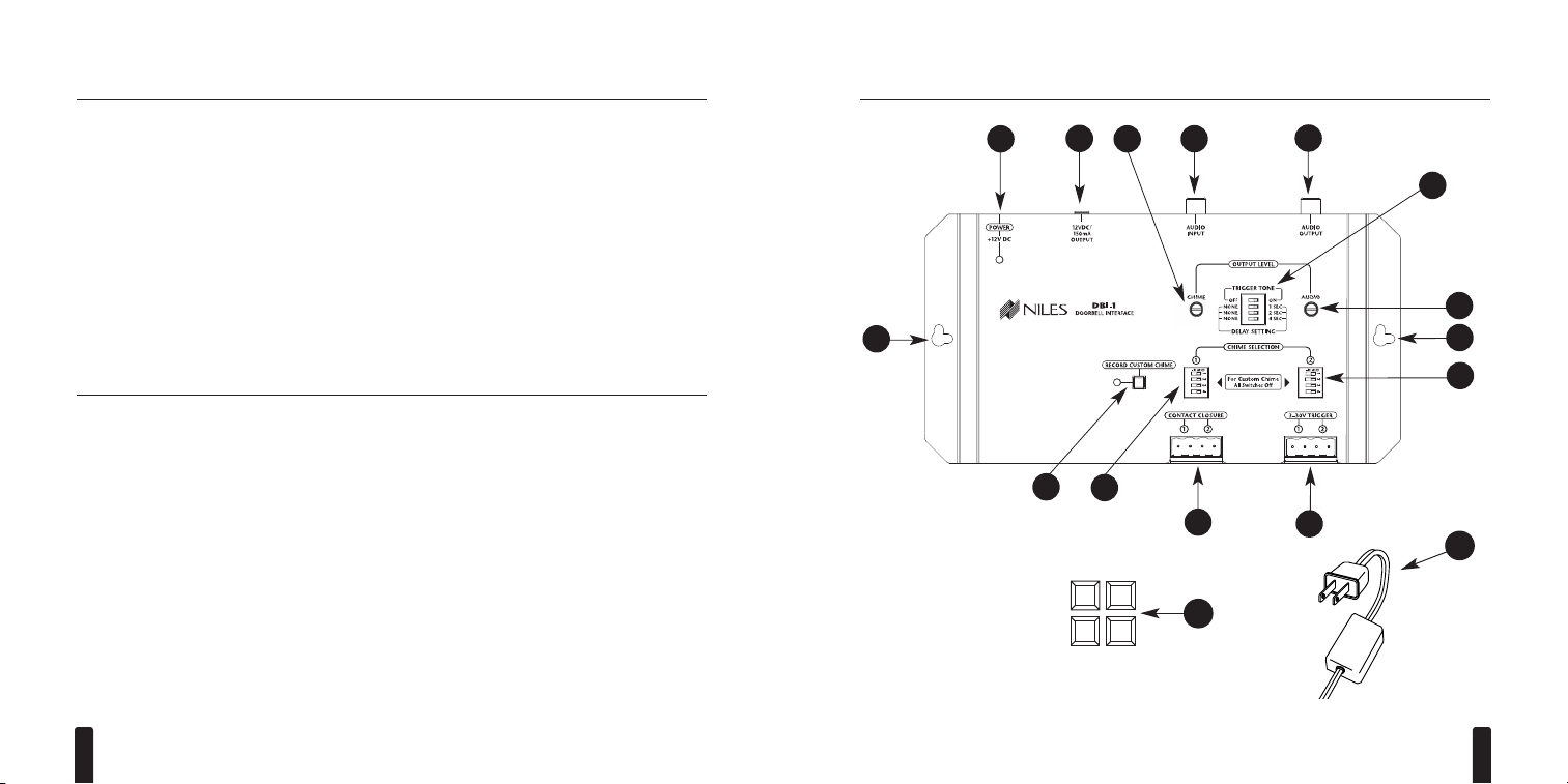
Figure 1
DESCRIPTION
(a) Screw Holes for Mounting
(screws not included)
(b) DC Power Jack and red LED Power
Indicator
(c) 12V DC 150mA Voltage Trigger Output
(d) Chime Output Level Adjustment
(e) RCA Audio Input
(f) RCA Audio Output
(g) Trigger Tone and Delay Settings
(h) Audio Output Level Adjustment
(i) Chime Selection 2 DIP Switches
(j) Chime 1 and 2 Voltage Triggers
(k) Chime 1 and 2 Contact Closure Triggers
(l) Chime Selection 1 DIP Switches
(m) Custom Chime Record Button and
Record Indicator
(n) Rubber feet for Table Top Mounting
(o) UL-listed, Universal Voltage Power Supply
Page 4

D OORBELL I NTERFACE
7
D OORBELL I NTERFACE
6
OPERATION OVERVIEW
The DBI-1 is operated by the door bell switches and automation systems that connect to the
contact closure and voltage trigger inputs. Triggers for two individual chimes (Chime
Selection 1 & Chime Selection 2) are provided for a front and rear door.
INSTALLATION COSIDERATIONS
• Included mounting wings and rubber feet provide for either table top or screw down mounting (see Figure 1 on page 5).
• The included UL-listed, universal voltage power supply provides power to the DBI-1
(see Figure 2 on pages 8-9).
• The DBI-1 connects to the Paging Input of a Niles MultiZone Control System using a standard audio cable with male RCA connectors (see Figure 2 on pages 8-9).
•A paging system connects to the Audio Input of the DBI-1 using an RCA audio cable
(see Figure 2 on pages 8-9).
• Doorbell momentary contact closure and momentary voltage triggers connect to the DBI-1
using two conductor wire (see Figure 2 on pages 8-9).
INSTALLATION
Mounting the DBI-1
Once you have decided on the location for the DBI-1 (generally near the location of the Niles
MultiZone Control System), make sure that the 12V DC power adapter and all cables are disconnected while mounting.
The DBI-1 can be either mounted on the back of a cabinet or on a wall using screws (not included). Also, it can be placed on a shelf using the included adhesive rubber feet (see Figure 1 on
page 5).
Connecting the DBI-1
1. Connect the Audio Output of the DBI-1 to the Paging Input of a Niles MultiZone System
(see Figure 2 on pages 8-9).
2. (Optional) Connect the Audio Output of a paging system to the Audio Input of the DBI-1
(see Figure 2 on pages 8-9).
3. Connect the voltage and or contact closure trigger cables to the and Chime
Triggers (see Figure 2 on pages 8-9).
4. (Optional) Connect the 12V DC Voltage Trigger Output to a voltage activated device.
(see Figure 2 on pages 8-9).
5. Connect the included 12V DC in-line power adapter’s voltage output plug into the DBI-1’s
power jack and then plug its AC power cord into an unswitched AC outlet (see Figure 1).
The red LED power indicator will illuminate to confirm proper power connection.
Page 5

D OORBELL I NTERFACE
9
D OORBELL I NTERFACE
8
Audio Input for Voice Paging
and Custom Chime Recording
Audio Output
Output Level for
Chime and Audio
Voltage Trigger
for Activating Amplifiers
Power Supply
Page Input
Niles MultiZone Control System
Standard Audio Cable
with Male RCA Connectors
Front Doorbell Rear Doorbell
Chime Selection
Dip Switches
Custom Chime
Record Button
Contact
Closure
Designated
as Chime 2
Voltage
Designated
as Chime 1
Figure 2
Page 6

D OORBELL I NTERFACE
10
D OORBELL I NTERFACE
11
INSTALLATION SETTINGS
Contact Closure Triggers - Contact closure trigger inputs provide for two independent
chime triggers. When triggered, the selectable trigger tone, assigned delay and chime are
executed.
3V-30V Voltage Triggers - Voltage trigger inputs provide for two independent chime trig-
gers. When triggered, the selectable trigger tone, assigned delay and chime are executed.
Note: Voltage triggers are not polarity dependent.
Chime and Audio Level Adjustments - Adjustable output level for the selected chime
and the connected paging system.
Note: The Audio Level Adjustment does not affect an audio input signal that is being
recorded for a Custom Chime. The Custom Chime record level must be adjusted external at the audio source.
Important: Lowering the chime and audio level will prevent sound distortion.
Setting the Tone/Delay - Four DIP switches provide a selectable trigger tone and various
delays between when a chime is triggered and when the chime is actually generated.
Turning switch 1 ON enables a trigger tone that activates the audio sensing of the Paging
Input of a Niles MultiZone System. Switches 2, 3 and 4 ON enable delay times. The delay
time provided for each switch is indicated in the table below.
Delay times are summed together when multiple switches are
selected (e.g. 2 and 3 = 3 seconds). There is no delay included
if none of these DIP switches are selected.
Notes: 1. The chime contact and voltage triggers are ignored
during a chime. 2. A triggered chime is delayed 8 seconds after
the completion of a chime when a trigger tone or any amount of
delay is selected.
Switch
All OFF
2 ON
3 ON
4 ON
Delay
No Delay
1 second
2 second
4 second
INSTALLATION SETTINGS (Continued)
Recommended Tone/Delay Settings
Identifying the Version of a Niles MultiZone System
The ZR-4630 and ZR-8630AV will display their version on the front panel LCD display
when first powered on. The A4.6Ci contains the version letter in its serial number located on the bottom panel.
Niles MultiZone System
Niles ZR-4630
Niles ZR-4630
Niles ZR-8630AV
Niles A4.6Ci
Version
Ver. 1.00 ~ 1.11
Ver. 1.12 ~ 1.16
Ver. 1.00 ~ 2.00
Ver. A ~ B
Recommended Setting
Tone On with seven seconds of
delay (switches 1, 2, 3 and 4 ON)
Tone On with three seconds of
delay (switches 1, 2, 3 ON)
Tone On with three seconds of
delay (switches 1, 2, 3 ON)
Tone On with four seconds of
delay (switches 1 and 4 ON)
Page 7

D OORBELL I NTERFACE
13
D OORBELL I NTERFACE
12
INSTALLATION SETTINGS (Continued)
Chime Selection - Two banks of DIP switches (Chime Selection 1 and Chime selection 2) pro-
vide independent selection of all the available chimes. The lowest number DIP switch takes
priority if more than one switch is selected. The table below identifies the selectable chime
for each DIP switch.
Switch
1
2
3
4
None
Chime
Standard Chime Recommended for a Front Door
Westminster Chime Recommended for a Front Door
Standard Chime Recommended for a Rear Door
Westminster Chime Recommended for a Rear Door
Recorded Custom Chime
INSTALLATION SETTINGS (Continued)
Recording a Custom Chime - A mono analog audio signal can be recorded by the DBI-1 to
create a Custom Chime. Analog audio signals to be recorded connect to the Audio Input.
Stereo audio signals can be adapted to mono using an RCA “Y” Adapter Cable.
The DBI-1 was designed to record a Custom Chime at the same volume as the selectable
chimes when recording the output of a typical CD player (@ 2V RMS). The record level
for a Custom Chime must be adjusted externally at the audio source. Some trial and error
will be required to obtain an exact volume match between a recordable Custom Chime
and a selectable chime.
Recording an Active Audio Signal
1. Press the record button to begin recording the audio signal (the recording starts immediately and the record LED flashes red).
2. The recording process will end after 12 seconds (when it is complete, the record LED
turns off). Pressing the record button anytime before the 12 seconds have elapsed also
ends the recording (the record LED turns off).
Recording a Paused Audio Signal
1. Press the record button while there is no audio signal present at the audio input. This
causes the DBI-1 to go into a record standby mode (the record LED lights solid red).
2. Activate the audio input signal. The recording will begin the moment an audio signal
is sensed (the record LED flashes red).
3. The recording process will end after 12 seconds (when it is complete, the record LED
turns off). Pressing the record button anytime before the 12 seconds have elapsed also
ends the recording (the record LED turns off).
Page 8

D OORBELL I NTERFACE
15
SPECIFICATIONS
Audio
• Chime: 100Hz ~ 3kHz, +/- 3dB
• Audio Pass Through: 10Hz ~ 50kHz, +/- 0.5dB
Trigger Inputs
• Voltage Trigger Input: 3V-30V AC/DC
• Contact Closure Inputs: < 100 ohms
Power Supply
• INPUT: 100-240V AC 50-60Hz 40W
• OUTPUT: 12V DC 1.2 A
Unit Dimensions
• 7-7/8" wide x 1-1/8" high x 4-1/8" deep
NOTES
D OORBELL I NTERFACE
14
 Loading...