

Page 1

ZR
-
6
Page 2

NILES AUDIO CORPORATION – 1-800-BUY-HIFI – 305-238-4373
Page 3
INTRODUCTION
CONGRATULATIONS!
Thank you for purchasing the Niles ZR-6 MultiZone Receiver. With proper installation and operation, you should enjoy years
of trouble-free use. Niles manufactures the industry’s most complete line of custom installation components and accessories for
audio/video systems. To see the complete Niles product assortment, visit us on the Internet at: www.nilesaudio.com
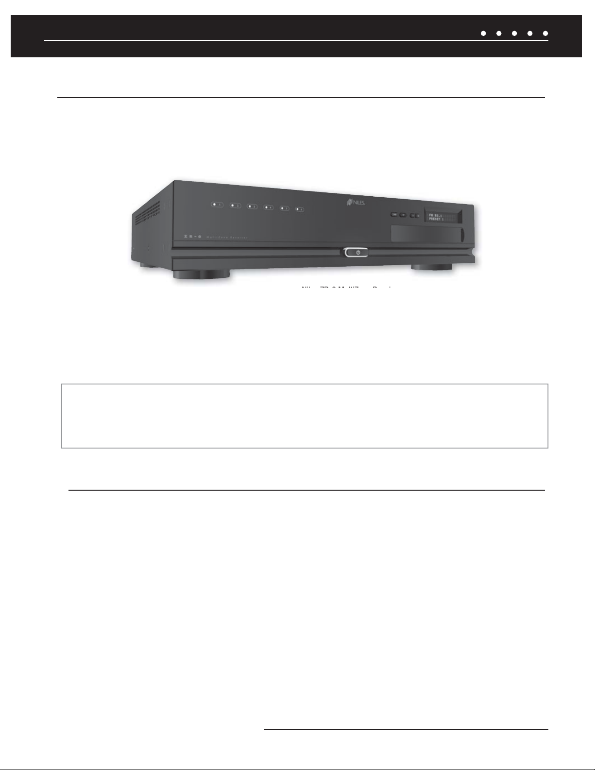
Figure 1. Niles ZR-6 MultiZone Receiver
The Niles ZR-6 MultiZone Receiver is the centerpiece of a six-source, six-zone distributed home entertainment system. Up to six
stereo audio sources, including the built-in AM/FM tuner, can be connected, distributed, and controlled throughout the home. The ZR-6
MultiZone Receiver features plug-and-play iPod integration, with metadata supported. There are three User Interface Keypads available
for control, with an accessory keypad available for additional functionality. When partnered with the Niles VS-6 High Defi nition
Component Video Switcher, the ZR-6 system will also distribute high defi nition video to any of the six zones.
ZR-6 FIRMWARE UPDATE
To ensure proper system operation, all devices in a ZR-6 system must have the latest fi rmware versions. To download the latest
fi rmware and for instructions on how to install it, visit the Niles Audio tech support website at: www.nilesaudio.com/techsupport
BOX CONTENTS
• (1) ZR-6 MultiZone Receiver
• (1) Removable Power Cable
• (1) 2 meter iPod Interconnect Cable
• (2) Rack Mount Ears
• (1) R-8L Hand-Held Learning Remote Control
• (1) Safety Sheet
After unpacking and before installation, carefully inspect the contents. If any damage is discovered due to shipping, contact Niles for
assistance (see back cover or Warranty Card for contact information).
• (1) System Guide
• (1) Warranty Card
• (1) FM Dipole Antenna
• (1) AM Loop Antenna
• (1) R-6L and R-8L IR Code Guide
1NILES AUDIO CORPORATION – 1-800-BUY-HIFI – 305-238-4373
Page 4
INTRODUCTION
TABLE OF CONTENTS
Introduction
° Features and Benefits 4
System Parts Guide
° ZR-6 MultiZone Receiver 5
° TS-Pro Color Touchscreen 9
° Solo
° Solo
° Numeric
®
-6MD Master Keypad 10
®
-6IR Master Keypad 11
™
-6P Accessory Keypad 12
° R-8L Learning Remote Control 13
System Wiring Diagrams
° Stand-Alone ZR-6 MultiZone Receiver 14
° Including Distributed Video with a Niles VS-6 High Definition Component Video Switcher 16
° Expanding to 18 Zones with Additional ZR-6 MultiZone Receiver(s) 18
° ZR-6 MultiZone Receiver Integrated with a Home Theater System 22
° Adding an External RS-232 Control System to the ZR-6 MultiZone Receiver 23
° Adding Additional Keypads to a Zone 24
° Adding an External Amplifier to Zone 4, 5 and 6 25
° Adding System Paging from External Telephone System, Intercom System and/or Doorbell 26
System Installation
° ZR-6 MultiZone Receiver 27
° Solo-6IR Master Keypad 31
° Solo-6MD Master Keypad 32
° Numeric-6P Accessory Keypad 33
° TS-Pro Color Touchscreen 34
NILES AUDIO CORPORATION – 1-800-BUY-HIFI – 305-238-43732
Page 5
INTRODUCTION
TABLE OF CONTENTS
System Configuration 35
IR Programming 40
System Archiving/Updating 50
System Settings
° AM/FM Tuner 51
° Solo-6IR Keypad 52
° Solo-6MD Keypad 53
° TS-Pro Color Touchscreen 56
Programming the Remote 60
Operating the ZR-6 MultiZone Receiver
° From the Solo-6IR Keypad 63
° From the Solo-6MD Keypad 65
° From the TS-Pro Color Touchscreen 69
° From the R-8L Learning Remote Control 70
Troubleshooting 71
Specifications 74
RS-232 Control Protocols 75
Appendix A: Device Source Screen Library 79
IR Programming Worksheets 88
3NILES AUDIO CORPORATION – 1-800-BUY-HIFI – 305-238-4373
Page 6

INTRODUCTION
FEATURES AND BENEFITS
SIX-SOURCE, SIX-ZONE MULTIZONE RECEIVER — The ZR-6 independently distributes up to six audio sources to up to
six zones to provide high-quality entertainment throughout the home.
BUILT-IN AM/FM TUNER — A digital AM/FM tuner with 20 preset stations is built into the ZR-6 MultiZone Receiver to provide
radio reception without any additional components, connections, or programming.
PLUG-AND-PLAY iPod INTEGRATION — The ZR-6 MultiZone Receiver includes a 30-pin iPod connection cable to fully
integrate this popular audio source into the system. Metadata is supported. NOTE: Only USB Hosting iPods are supported. See the iPod
Compatibility Chart for details.
HAND-HELD LEARNING REMOTE CONTROL — The included learning remote control “learns” the commands to operate
the ZR-6’s source audio components and comes pre-loaded with IR codes for today's most popular brands of equipment. In addition,
the remote also has the ability to build IR sequences.
CHOICE OF COMPATIBLE KEYPADS — The Solo-6IR Master Keypad offers basic system control. The Solo-6MD Master Keypad
adds an LCD screen with metadata. The TS-Pro provides color touchscreen control with metadata. The Numeric-6P Accessory Keypad
can be combined with the Solo-6IR for additional functionality and control.
12-CHANNEL DIGITAL AMPLIFIER — The effi cient digital amplifi er delivers 50 watts to each zone (8 ohms, any zone driven).
RS-232 AND DISCRETE IR CONTROL — Control systems from both Niles and other manufacturers can be seamlessly
integrated with the ZR-6 MultiZone Receiver.
PREAMPLIFIER OUTPUTS WITH 12V TRIGGERS — Zones 4, 5, and 6 are equipped with preamplifi er outputs to
®
accommodate external power amplifi ers such as Niles Systems Integration Amplifi ers
to automate amplifi er turn-on and turn-off (see
FIGURE 9).
. Each preamplifi er output includes a 12V trigger
SYSTEM-WIDE AUDIO PAGING — The ZR-6 MultiZone Receiver has circuitry that automatically mutes the audio and plays
doorbell chimes and telephone pages through the system’s loudspeakers. When done, the audio automatically returns to its previous
level. Doorbell chimes require the DBI-1 Doorbell Interface.
CUSTOM-TAILORED SOUND — With separate bass, treble, and variable loudness adjustments on each keypad, each zone is
easily calibrated for high-quality sound and balanced acoustics from room to room.
EXPANDABLE TO 18 ZONES — The system architecture allows you to expand the system to up to 18 zones by adding
additional ZR-6 MultiZone Receivers. When multiple ZR-6 MultiZone Receivers are combined, each unit’s built-in AM/FM tuner remains
active, making it possible to tune in different radio stations in each bank of zones (see
FIGURE 5).
SUPPORTS UP TO THREE KEYPADS IN EACH ZONE — With the addition of a ZR-KE Keypad Expander, any zone can
accommodate up to three keypads. Ideal for large rooms, bedrooms, and outdoor applications (see
FIGURE 8).
ZONE LINKING — Permanently group up to six zones per chassis. Turn-on, source selection, and turn-off all work in unison, while
retaining independent volume, bass, treble, and variable loudness in each zone.
PARTY OR WHOLE HOUSE MODE — Turns on all the zones in the house (or a pre-set number of zones) to the same audio
source for background music while entertaining.
VIRTUAL HOME THEATER ZONE — The ZR-6 MultiZone Receiver can share sources with an independent home theater
system via the Global IR input and Home Theater Sync connections.
NILES AUDIO CORPORATION – 1-800-BUY-HIFI – 305-238-43734
Page 7
SYSTEM PARTS GUIDE
ZR-6 MULTIZONE RECEIVER FRONT PANEL
1
2
3
4
5
6
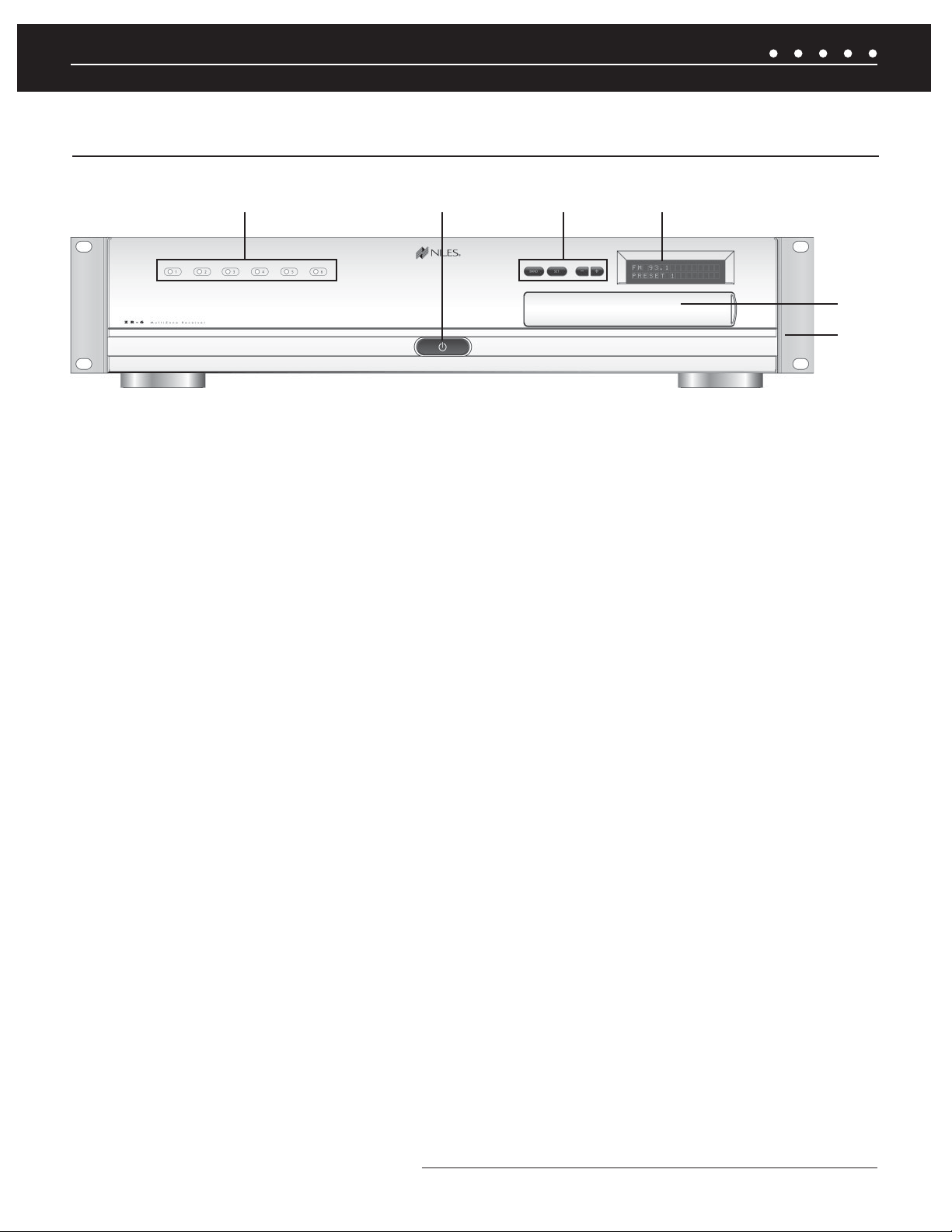
1) LED ZONE ON/OFF INDICATORS — Individually illuminate when the corresponding zone is active, turn off when the zone
is off, and provide diagnostic information about the zone.
2) MAIN POWER SWITCH — Push-button, latching switch turns the main power to the ZR-6 MultiZone Receiver ON and OFF.
3) BAND, SET, –, AND + PUSH BUTTONS — Used to operate the AM/FM tuner, set favorite preset stations into memory,
and perform system confi guration operations.
4) BACKLIT LCD DISPLAY — Two-line, 16-character, LCD display shows current tuner preset, band, programming, diagnostics
information, and menus during confi guration.
5) PROGRAMMING PANEL — Behind a removable cover are the installer programming buttons and connections.
6) RACK MOUNT EARS — Two metal rack-mount ears are included and can be attached for installing the ZR-6 MultiZone
Receiver into a professional rack.
(CONTINUED ON NEXT PAGE)
5NILES AUDIO CORPORATION – 1-800-BUY-HIFI – 305-238-4373
Page 8
SYSTEM PARTS GUIDE
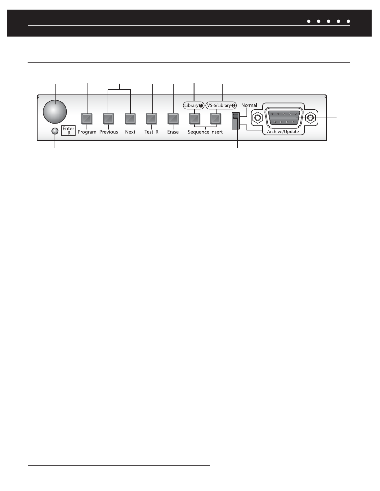
ZR-6 MULTIZONE RECEIVER PROGRAMMING PANEL
7
16
8
9
10
11
12
13
15
7) IR RECEIVER — Receives the IR codes from hand-held remotes during programming.
8) PROGRAM BUTTON — Enters and exits ZR-6 MultiZone Receiver IR programming and editing mode.
9) PREVIOUS AND NEXT BUTTONS — Step forward and backward through each part of the programming process.
10) TEST IR BUTTON — Transmits the last-learned IR code out of its respective IR output to verify correct operation.
11) ERASE BUTTON — Erases various parts of the ZR-6 MultiZone Receiver memory.
14
12) SEQUENCE INSERT (LIBRARY 1) — Inserts the stored IR commands from Library 1 into sequences to control source devices.
13) SEQUENCE INSERT (VS-6/LIBRARY 2) — Inserts pre-loaded VS-6 High Defi nition Video Switcher IR commands and/
or additional stored IR commands from Library 2 into sequences to control source devices.
14) ARCHIVE/UPDATE PORT — Used to connect a computer for archiving and restoring previously saved ZR-6 confi gurations
and or updating the fi rmware of the ZR-6 MultiZone Receiver and connected keypads.
15) PROGRAMMING SLIDE SWITCH — Disables the rear RS-232 connection and activates the front RS-232 connection for
archiving, setup, and fi rmware updates.
16) IR STATUS LED — Indicates reception of IR codes by the ZR-6 MultiZone Receiver.
NILES AUDIO CORPORATION – 1-800-BUY-HIFI – 305-238-43736
Page 9
SYSTEM PARTS GUIDE
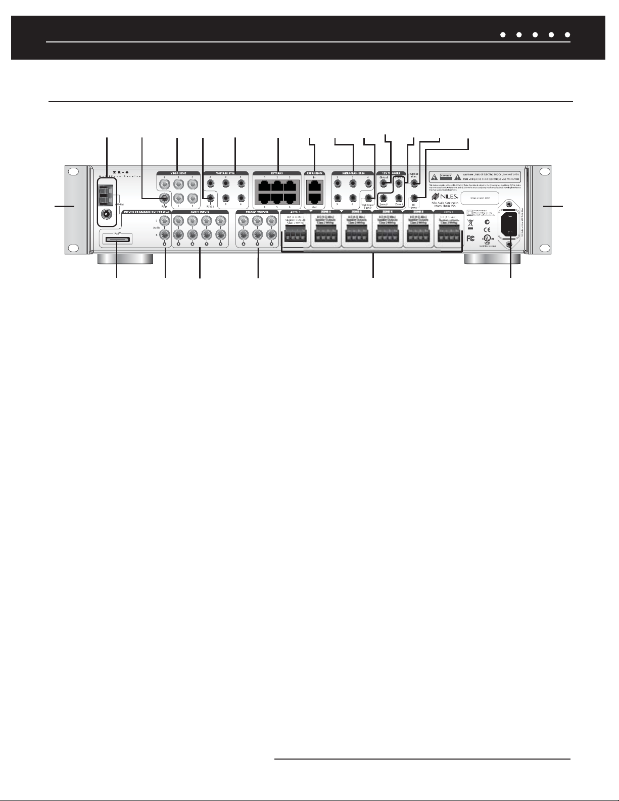
ZR-6 MULTIZONE RECEIVER REAR PANEL
17
18 19 21
20
22
23
24
25
26 27
28
29
30
L+ L- R- R+L+ L- R- R+
36
35
34
33
32
31
17) AM/FM ANTENNA CONNECTIONS — For connecting the supplied AM and FM antennas.
18) PAGING INPUT — Connects to a compatible telephone system, intercom system and/or a doorbell (see FIGURE 10).
19) VIDEO SYNC INPUTS — Determines on/off status of connected video device by detecting presence of a video signal.
20) RS-232 PORT — A 3.5 mm stereo mini-jack is used to provide RS-232 serial communication so the ZR-6 MultiZone Receiver
can be monitored and controlled by an external control system.
30
21) VOLTAGE SYNC INPUTS — Determine the on/off status of connected source devices by detecting the presence of a
trigger voltage between 3V and 30V, AC or DC.
22) KEYPAD PORTS — Six zone-specifi c RJ-45 jacks are used to connect the keypads with CAT-5 cable.
23) EXPANSION PORTS — Two RJ-45 jacks are used to connect the Master MultiZone Receiver to the Slave MultiZone
Receivers using CAT-5 cable.
24) MICROFLASHER® OUTPUTS — Five 3.5 mm stereo mini-jacks are used to connect the optional Niles MicroFlashers
(FG01019) to control the source devices.
25) HIGH OUTPUT FLASHER — A single 3.5 mm mini-jack is used to connect an optional Niles IRB1 High Output IR Flasher
(FG01023) to control multiple devices from a single fl asher.
26) GLOBAL 12V TRIGGER OUTPUT — A single 3.5 mm mini-jack is used to provide a 12V DC trigger to automate the
power turn-on and turn-off of connected devices such as a Niles AC-3 Voltage-triggered AC Power Strip (FG00242).
7NILES AUDIO CORPORATION – 1-800-BUY-HIFI – 305-238-4373
Page 10

SYSTEM PARTS GUIDE
ZR-6 MULTIZONE RECEIVER REAR PANEL (CONTINUED)
27) ZONE FOUR, FIVE, AND SIX 12V TRIGGER OUTPUTS — Three 3.5 mm mini-jacks are used to provide a 12V DC trigger
to automate the power turn-on and turn-off of zone-specifi c connected devices such as Niles Systems Integration Amplifi ers.
28) GLOBAL IR INPUT — A single 3.5 mm mini-jack is used to provide an input connection for IR commands from an external
control system such as the Niles iC2
™
Home Theater Automation System (FG01342).
29) HT (HOME THEATER) SYNC INPUT — A single 3.5 mm mini-jack is used to detect voltage from a connected home
theater system to let the ZR-6 MultiZone Receiver know when the home theater is on.
30) RACK MOUNT EARS — Two metal rack-mount ears are included and can be attached for installing the ZR-6 MultiZone
Receiver into a professional rack.
31) IEC POWER CABLE CONNECTOR — Two-pin connector for the removable power cord.
32) LOUDSPEAKER TERMINALS — A removable terminal is provided for each of the six zones. Accepts speaker wire up to
14 AWG .
33) ZONE FOUR, FIVE, AND SIX PREAMPLIFIER OUTPUTS — Three pairs of stereo RCA jacks are used to connect
external power amplifi ers. Can be switched between fi xed or variable output.
34) SOURCE AUDIO INPUTS — Four pairs of stereo RCA jacks are used to connect stereo audio to Sources 3-6.
35) SOURCE 2 AUDIO INPUT/iPod CASCADE AUDIO OUTPUT — A pair of stereo RCA jacks are used to provide an
analog input for a Source 2 external device when an iPod is not being used with the system. With an iPod, these jacks become
cascade audio outputs to route the iPod’s audio signal to a Slave ZR-6 MultiZone Receiver.
36) iPod CONNECTOR — A 30-pin connector is used to provide a connection for an iPod digital music player as Source 2.
NILES AUDIO CORPORATION – 1-800-BUY-HIFI – 305-238-43738
Page 11
SYSTEM PARTS GUIDE
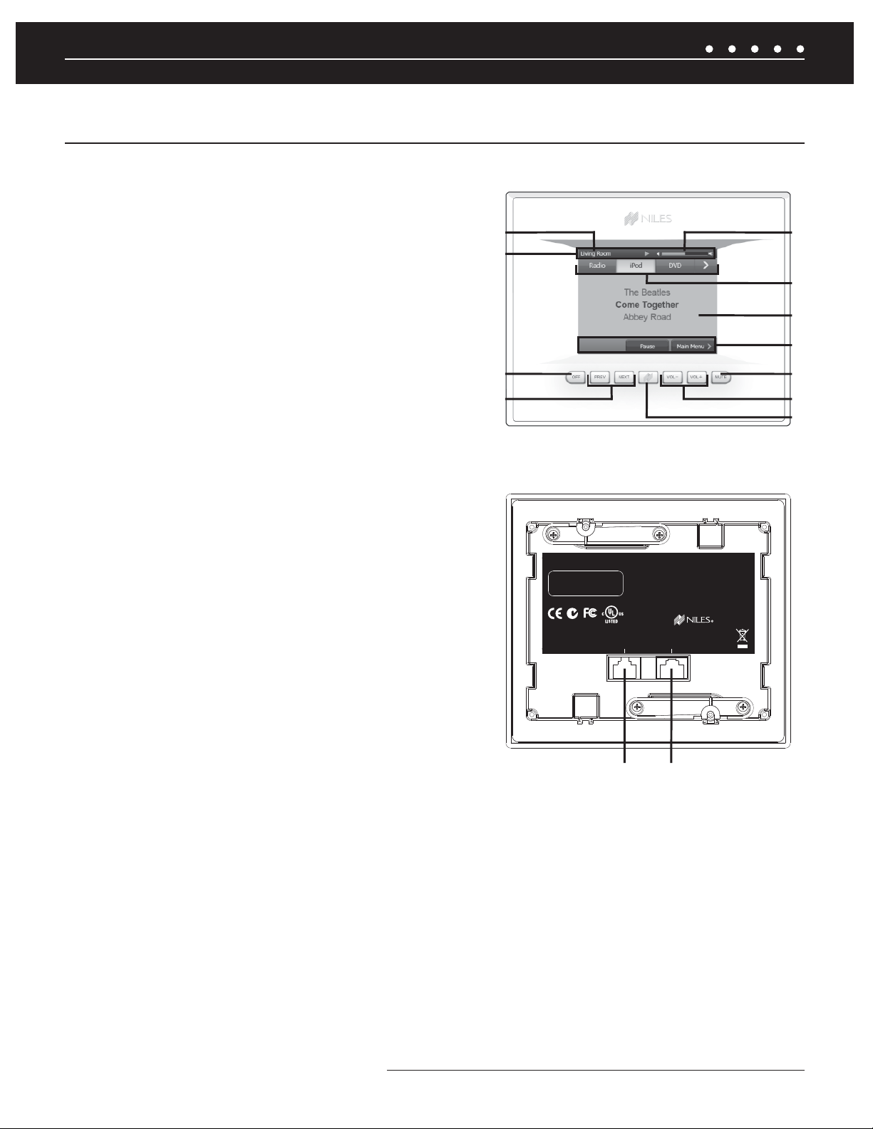
TS-PRO COLOR TOUCHSCREEN CONTROLLER (SOLD SEPARATELY)
1) ACTIVE ROOM — Indicates which room is being controlled by this
touch screen.
2) STATUS BAR — Displays status of currently selected device; Play,
Pause, Mute and Shuffl e indicators appear here when appropriate.
3) VOLUME LEVEL — Visual display of current volume level
4) MASTER KEYS — Six custom-labeled touchscreen buttons to
provide One Touch to Music
®
.
5) SOURCE FUNCTION FIELD — Displays metadata from a
connected iPod, station information from the ZR-6's built-in radio,
and control screens for the connected sources.
6) NAVIGATION KEYS — Navigate through various control screens
for a device; device control functions sometimes appear here.
7) OFF — Turns zone off; Press-and-hold turns entire system off.
8) PREV/NEXT — Next or Previous track or channel for the currently
playing device
9) NILES KEY — multi-function key; When the zone is off, a press of
this button activates the last played source; Press-and-Hold for three
seconds to access the setup menu (audio settings such as bass
and treble, display settings such as timeout and color selection, and
radio preset naming); Press-and-Hold for ten seconds to access the
confi guration menu (IR settings, Source level adjustments, turn on volume
and room naming).
Front Panel of TS-Pro
1
3
2
4
5
6
7
8
11
10
9
Rear Panel of TS-Pro
TS-PRO
SERIAL # LABEL HERE
12VDC
0.25A
CLASS 2 DEVICE
Wall-Mount Color Touchscreen
This device complies with part 15 of the FCC
Rules. Operation is subject to the following two
conditions: (1) This device may not cause
harmful interference, and (2) this device must
accept any interference received, including
interference that may cause undesired operation.
© Niles Audio Corporation
Miami Florida, USA LA02755A
SYSTEMUTILITY ADAPTER
10) VOL-/VOL+ — Adjusts volume up and down.
13
12
11) MUTE — Mutes and un-mutes the active audio zone
12) SYSTEM CONNECTOR — Connects to the ZR-6 MultiZone Receiver via CAT-5.
13) UTILITY ADAPTER — An RJ-45 Adapter (FG01197) included with the TS-Pro is used to connect an external IR sensor, an
LS-IOP, or both.
.
9NILES AUDIO CORPORATION – 1-800-BUY-HIFI – 305-238-4373
Page 12
SYSTEM PARTS GUIDE
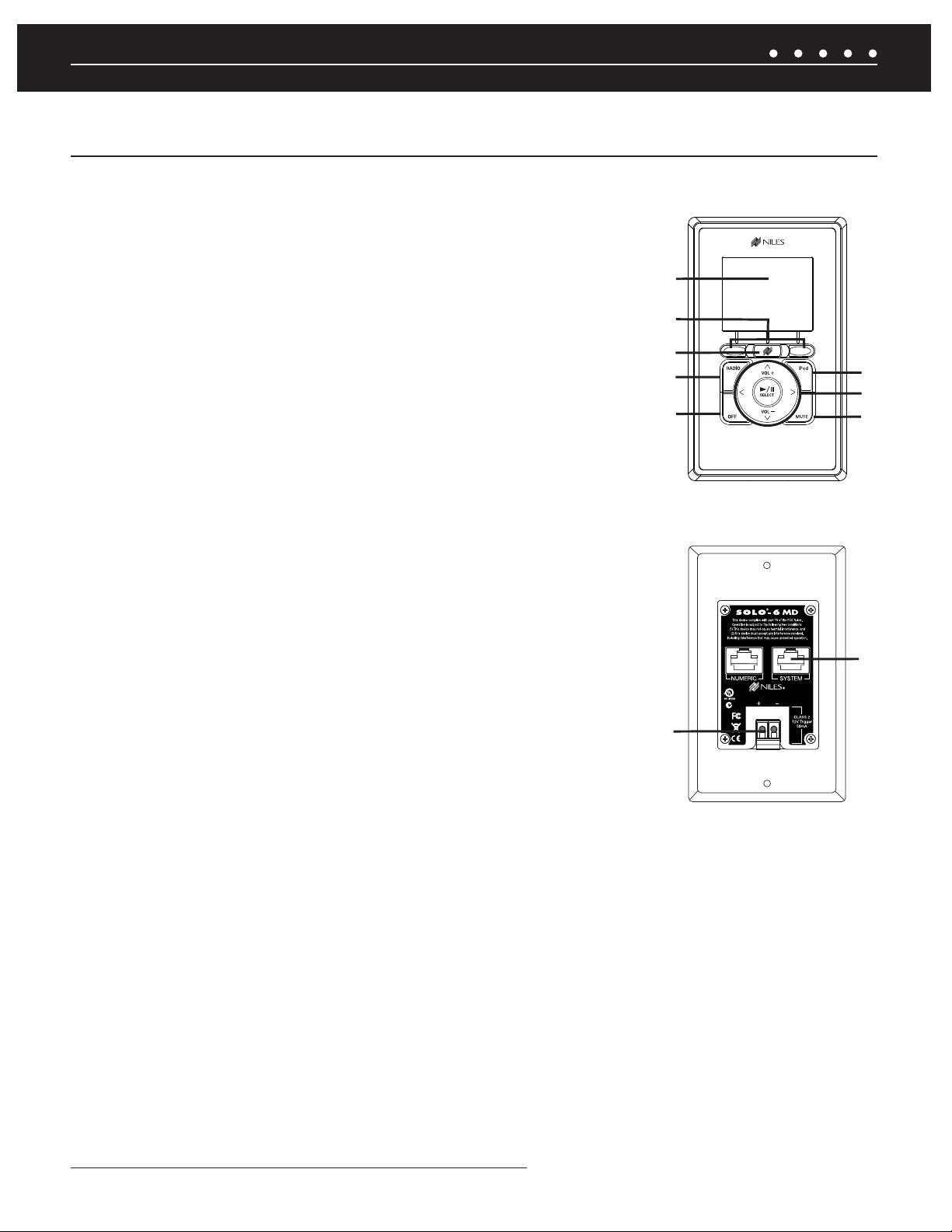
SOLO-6MD WEATHER-RESISTANT MASTER KEYPAD (SOLD SEPARATELY)
1) LCD DISPLAY — Provides source metadata, zone, and keypad information.
2) SOFT KEYS — The function of these keys appears in the LCD screen above and changes
based on the source or menu selected.
3) NILES KEY — Press to access the source selection menu. Press-and-hold for three
seconds to access the keypad setup menu. Press-and-hold for ten seconds to access the
keypad confi guration menu. With the Zone off and the keypad backlight off, it selects the last
played source.
4) RADIO KEY — Provides One Touch To Entertainment
™
simplicity for the AM/FM tuner.
5) OFF KEY — Press this key to turn the local zone off. Press-and-hold this key for three
seconds to turn off all zones.
6) iPod KEY — Provides One Touch To Entertainment
™
simplicity for the connected iPod.
7) CONTROL KEYS — Include Volume Up and Volume Down plus playback functions such as
Play, Pause, Previous, and Next.
8) MUTE KEY — Mutes the sound in the zone
Front Panel of Solo-6MD
1
2
3
4
5
Rear Panel of Solo-6MD
6
7
8
9) LS-IOP CONTROL OUTPUT — A 12V control output that activates when the keypad
is on.
10) SYSTEM PORT — An RJ-45 jack is used to connect the keypad to the Keypad Port of
the ZR-6 MultiZone Receiver.
10
9
NILES AUDIO CORPORATION – 1-800-BUY-HIFI – 305-238-437310
Page 13
SYSTEM PARTS GUIDE
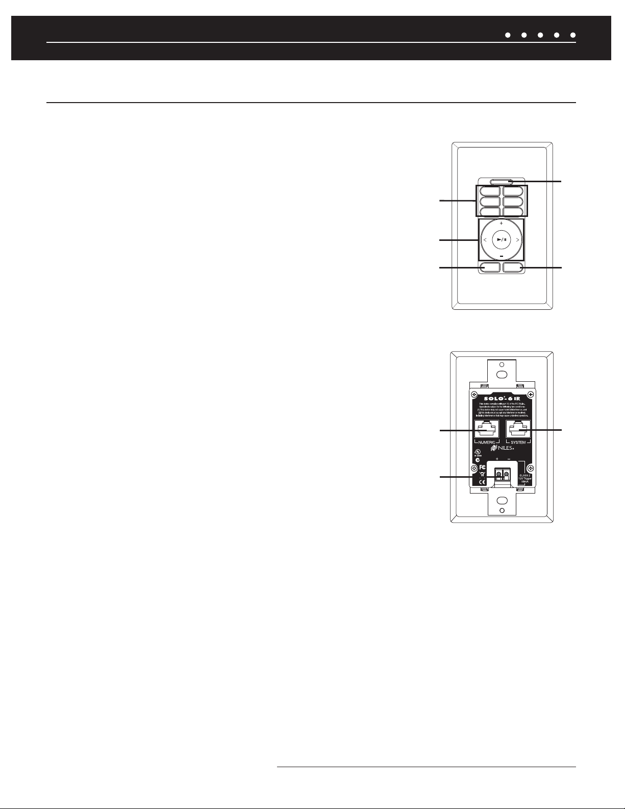
SOLO-6IR WEATHER-RESISTANT MASTER KEYPAD (SOLD SEPARATELY)
1) MASTER KEYS — Custom labeled keys that turn the zone on and play the selected
source device.
2) CONTROL KEYS — Include Volume Up and Volume Down plus playback functions such as
Play, Pause, Previous, and Next.
3) OFF KEY — Press this key to turn the local zone off. Press-and-hold this key for three
seconds to turn off all zones.
2
4) BUILT-IN IR SENSOR — A plasma and LCD-proof IR sensor
5) MUTE KEY — Mutes the sound in the zone.
6) NUMERIC PORT — An RJ-45 jack is used to connect the Solo-6IR Keypad to a Numeric-6P
Accessory Keypad (FG01442).
7) LS-IOP CONTROL OUTPUT — A 12V control output that activates when the keypad
is on.
8) SYSTEM PORT — An RJ-45 jack is used to connect the keypad to the Keypad Port of
the ZR-6 MultiZone Receiver.
Front Panel of Solo-6IR
RADIO
iPod
DVD
1
3
CD
VIDEO
SAT
VOL
VOL
MUTEOFF
Rear Panel of Solo-6IR
®
SOLO-4
This device complies with part 15 of the FCC Rules.
Operation is subject to the following two conditions:
(1) This device may not cause harmful interference, and
(2) this device must accept any interference received,
including interference that may cause undesired operation.
4
5
IR
©Niles Audio Corporation
6
Miami Florida, USA LA02461A
+ –
SYSTEM
CLASS 2
12V Trigger
50mA
8
7
11NILES AUDIO CORPORATION – 1-800-BUY-HIFI – 305-238-4373
Page 14
SYSTEM PARTS GUIDE
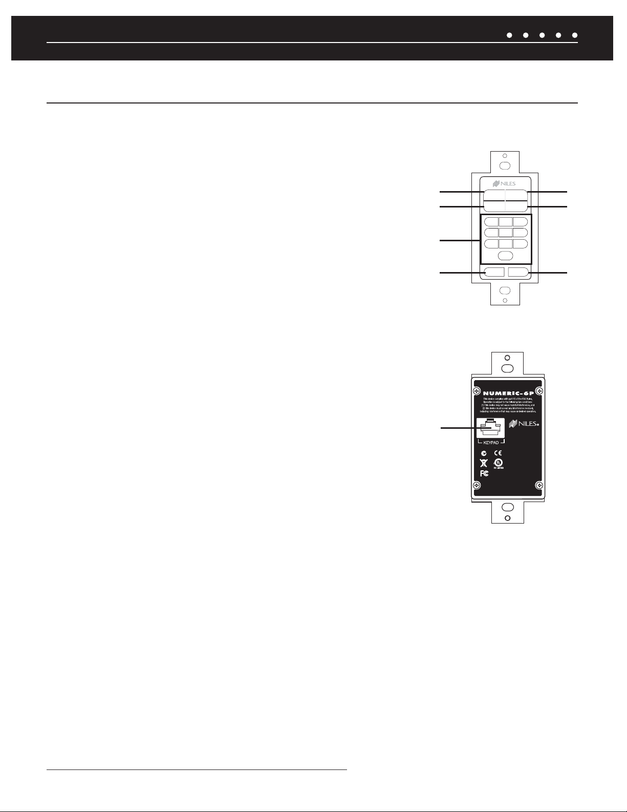
NUMERIC-6P WEATHER-RESISTANT ACCESSORY KEYPAD (SOLD SEPARATELY)
1) FAV KEY — Allows direct access of preset favorites using the 0-9 keys.
2) REPEAT KEY — Activates the repeat mode.
3) 0-9 KEYS — Provide direct access to radio stations, channels, and preset favorites.
4) LAST KEY — Returns to the previous channel.
5) DISC KEY — Activates the disc or album mode on an iPod, music servers and
other devices.
6) SHUFFLE KEY — Toggles the shuffl e (or random) mode on and off.
7) ENTER KEY — Required by some devices to enter channel numbers or for direct access.
8) KEYPAD PORT - An RJ-45 jack is used to connect the Accessory Keypad to the Solo-6IR.
Front Panel of Numeric-6P
1
2
3
4
FAV DISC
SHUFFLEREPEAT
ABC
1
DEF
2
4
MNO
JKL
5
7
STU
8
VWX
0
LAST ENTER
GHI
3
PQR
6
9
YZ
Rear Panel of Numeric-6P
5
6
7
8
NILES AUDIO CORPORATION – 1-800-BUY-HIFI – 305-238-437312
Page 15
0,
0
70-
4&56
*/'0
.&/6
-"45
.65&
65
3
".'.
'
43$$
43$$
"69"6
9
3&1-":
0.
(30
%*4$
'"7
1
(
&
(
&
43$$
43$
43$
$
SYSTEM PARTS GUIDE
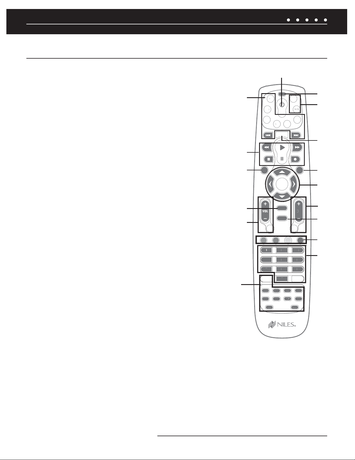
R-8L LEARNING REMOTE CONTROL (INCLUDED)
1) POWER BUTTON – Turns the selected source device on or off.
2) SOURCE SELECT BUTTONS – Turn the zone on and play the selected source device.
3) TRANSPORT BUTTONS – Used to skip backward, rewind, fast forward, skip
forward, stop, pause, or play tracks from the selected source.
4) MENU BUTTON – Displays a menu for the selected source device.
5) GUIDE BUTTON – Displays the program guide for the selected source device.
6) VOL -/+ AND MUTE BUTTONS – Raise and lower the volume level. Use the
MUTE button to completely mute the sound.
7)
EXTENDED FUNCTION BUTTONS - Provide additional functionality for advanced
features, menus, and guides.
8) SETUP BUTTON – Used when confi guring the R-8L remote.
9) TV/AUX BUTTON – Provides control of a local television and an additional
local source.
10) LIST BUTTON – Displays information from source devices that support this function.
1
2
1
8
9
''
-*45
10
3
4
11
12
5
6*%
9*5
6
13
14
15
11) INFO BUTTON – Displays the current channel and program information from source
devices that support this function.
12) MENU CURSOR BUTTONS
– Move the cursor in selected source device menu
screens. Press OK to choose the highlighted menu option or to toggle between AM and FM
tuner bands.
*/1
7
3"/%
61
&/5&
1(
13) CHANNEL SELECT AND LAST BUTTONS – Select the next or previous
channel and select the next or previous chapter on some DVD players. Press the Last
button to recall the last-viewed channel.
14) EXIT BUTTON – Exits the selected source device’s menu, guide, or program
without making a menu selection.
15) SPECIAL FUNCTION BUTTONS - Used to select the AM or FM radio bands and for special DVR menu functions. The red button
selects the AM radio band; the blue button selects the FM radio band.
16)
DIRECT ACCESS AND ENTER BUTTONS – Directly enter channels (for example: 09 or 31). Press the Enter button to send
channel number entry on certain TV models.
16
13NILES AUDIO CORPORATION – 1-800-BUY-HIFI – 305-238-4373
Page 16

SYSTEM WIRING DIAGRAMS
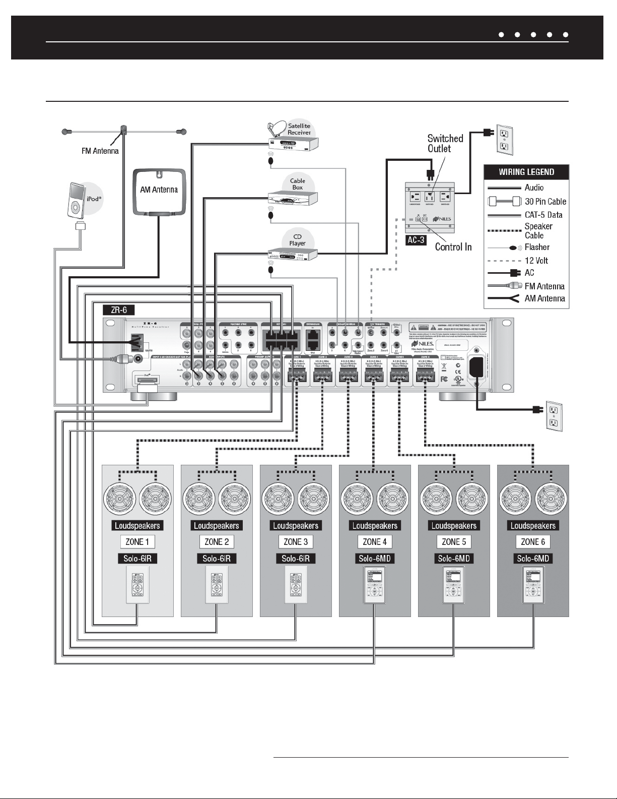
STAND-ALONE ZR-6 MULTIZONE RECEIVER
OVERVIEW
This diagram depicts a single Niles ZR-6 MultiZone Receiver installed to provide sound in six listening zones. Each zone includes a pair of
loudspeakers (sold separately) and a TS-Pro, Solo-6IR, or Solo-6MD Master Keypad (also sold separately).
SOURCE DEVICES
The ZR-6 MultiZone Receiver’s built-in AM/FM tuner is always Source 1. A 30-pin cable is included for the plug-and-play connection of an
®
Apple
iPod as Source 2. In this diagram, the audio outputs of three external source devices are routed to audio inputs 3, 4, and 5 on the
ZR-6 MultiZone Receiver.
MASTER KEYPADS
Master Keypads connect to the ZR-6 MultiZone Receiver by home runs of CAT-5 cable. The Solo-6IR Keypad provides basic system
functionality, while the step-up Solo-6MD Keypad adds an LCD screen that supports source device metadata. The TS-Pro Color
Touchscreen Controller is the ultimate interface with crisp graphics and fi ngertip control.
MICROFLASHERS
Niles MicroFlashers (sold separately) connect to the numbered MicroFlasher outputs to provide control over the source devices.
GLOBAL 12V CONTROL
A Niles AC-3 Voltage-Triggered AC Power Strip (FG00242) is connected to the Global 12V Control Output to automate source device turn-on
and turn off.
LOUDSPEAKERS
Each zone has a “home run” of speaker wire from the ZR-6 MultiZone Receiver to the loudspeaker locations. The receiver features
removable speaker wire terminals that accept speaker wire up to 14 AWG. Two pairs of 8 ohm loudspeakers wired in parallel (4 ohm load)
can be safely utilized in each zone without the amplifi er going into protection or shutting down.
ANTENNAS
The included FM dipole antenna attaches to the 75 ohm coaxial connector. The included AM loop antenna connects to the spring-loaded
terminals labeled AM and GND.
NILES AUDIO CORPORATION – 1-800-BUY-HIFI – 305-238-437314
Page 17
SYSTEM WIRING DIAGRAMS
STAND-ALONE ZR-6 MULTIZONE RECEIVERSTAND-ALONE ZR-6 MULTIZONE RECEIVER
Figure 3. Stand-Alone ZR-6 MultiZone Receiver
15NILES AUDIO CORPORATION – 1-800-BUY-HIFI – 305-238-4373
Page 18

SYSTEM WIRING DIAGRAMS
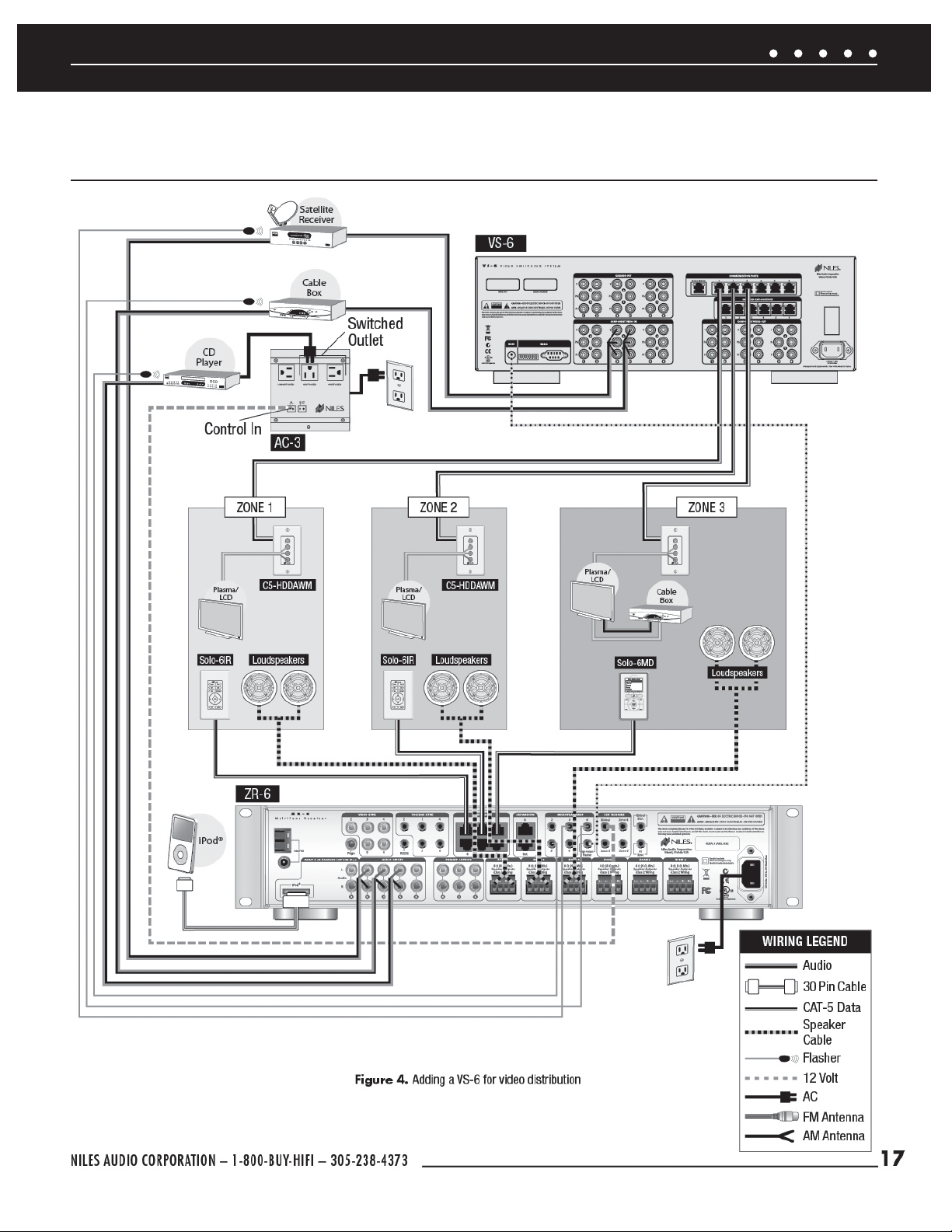
INCLUDING DISTRIBUTED VIDEO WITH A NILES VS-6 HIGH DEFINITION
COMPONENT VIDEO SWITCHER
OVERVIEW
A Niles VS-6 High Defi nition Component Video Switcher (FG01429) is added to distribute high defi nition video to displays in any
of the six zones.
CONTROL CONNECTION
A 3.5 mm stereo mini plug cable is connected between the ZR-6 MultiZone Receiver’s High Output Flasher Output Port to the VS-6 High
Defi nition Component Video Switcher’s IR input.
SOURCE DEVICES
The audio outputs from the source devices are routed to the ZR-6 MultiZone Receiver and the video outputs to the VS-6 High Defi nition
Component Video Switcher. When source selection sequences are stored in the ZR-6, video source selection is programmed using the
VS-6 codes which are stored in the ZR-6’s Library 2. Source inputs on the VS-6 must match those of the ZR-6. That is, source 3 on the
ZR-6 must connect to input 3 on the VS-6.
BALANCED VIDEO OUTPUT
The balanced video output from the VS-6 is sent to the video displays using CAT-5 cabling connected to Niles C5-HDDAWM Wall Mount
CAT-5 Component Video & Digital Audio Baluns (FG01374).
NILES AUDIO CORPORATION – 1-800-BUY-HIFI – 305-238-437316
Page 19
SYSTEM WIRING DIAGRAMS
INCLUDING DISTRIBUTED VIDEO WITH A NILES VS-6 HIGH DEFINITION
COMPONENT VIDEO SWITCHER
Figure 4. Adding a VS-6 for video distribution
17NILES AUDIO CORPORATION – 1-800-BUY-HIFI – 305-238-4373
Page 20

SYSTEM WIRING DIAGRAMS
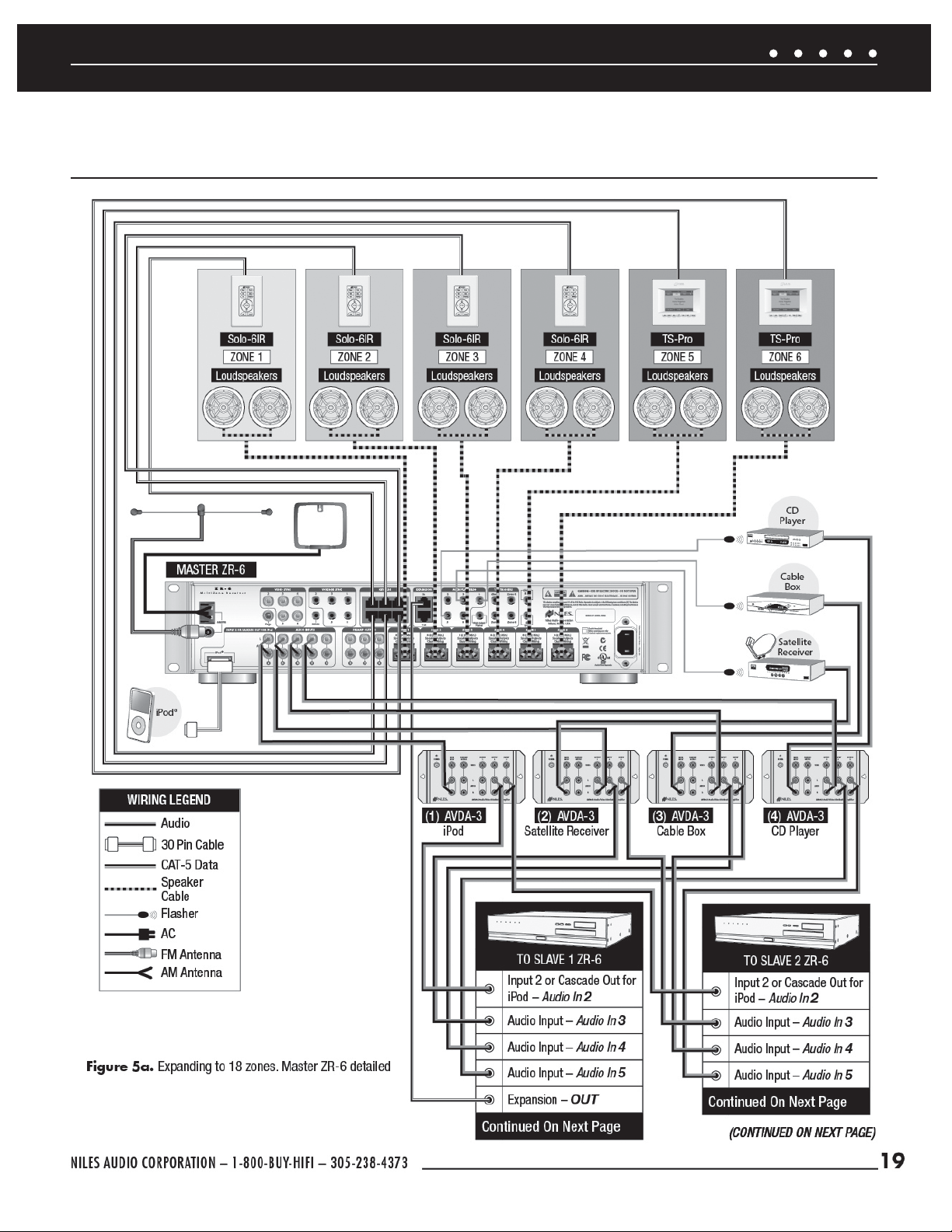
EXPANDING TO 18 ZONES WITH ADDITIONAL ZR-6 MULTIZONE RECEIVERS
Figures 5a, 5b, 5c
OVERVIEW
This diagram demonstrates the expendability of the ZR-6 MultiZone Receiver. Three ZR-6 MultiZone Receivers are integrated to create a
six-source, eighteen-zone distributed audio system.
EXPANSION PORTS
CAT-5 cables terminated with RJ-45 jacks are used to connect the ZR-6 MultiZone Receivers. One ZR-6 MultiZone Receiver is confi gured
as the Master; the other two as the Slaves. The Expansion In of the Master connects to the Expansion Out of Slave 1. The Expansion In of
Slave 1 connects to the Expansion Out of Slave 2 (See
System Confi guration
section).
SOURCE DEVICES
The audio outputs of the source devices must be routed to each ZR-6 MultiZone Receiver (Master and Slaves). This is best accomplished
using Niles AVDA-3 Source Level Stereo Audio/Video Distribution Amplifi ers (FG00814). When an iPod is connected to the Master chassis,
the Source 2 RCA jacks become cascade audio outputs. The cascade audio outputs are connected to Source 2 audio inputs on both Slaves.
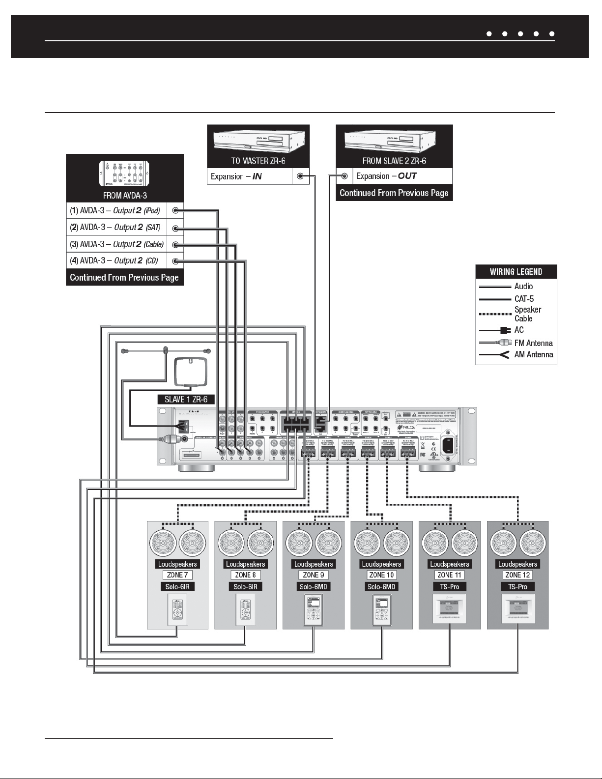
SOURCE DEVICE CONTROL
All MicroFlashers for source device control must be connected to the Master and not the Slave(s). All IR signals from the keypads
connected to the Slaves are routed to the Master via the expansion ports.
KEYPADS
Keypads for the additional zones are connected to the Slave’s keypad ports via CAT-5 cables terminated with RJ-45 jacks.
LOUDSPEAKERS
Each additional zone has a “home run” of speaker wire from the Slave ZR-6 MultiZone Receiver to the loudspeaker locations. The receiver
features removable speaker wire terminals that accept speaker wire up to 14 AWG.
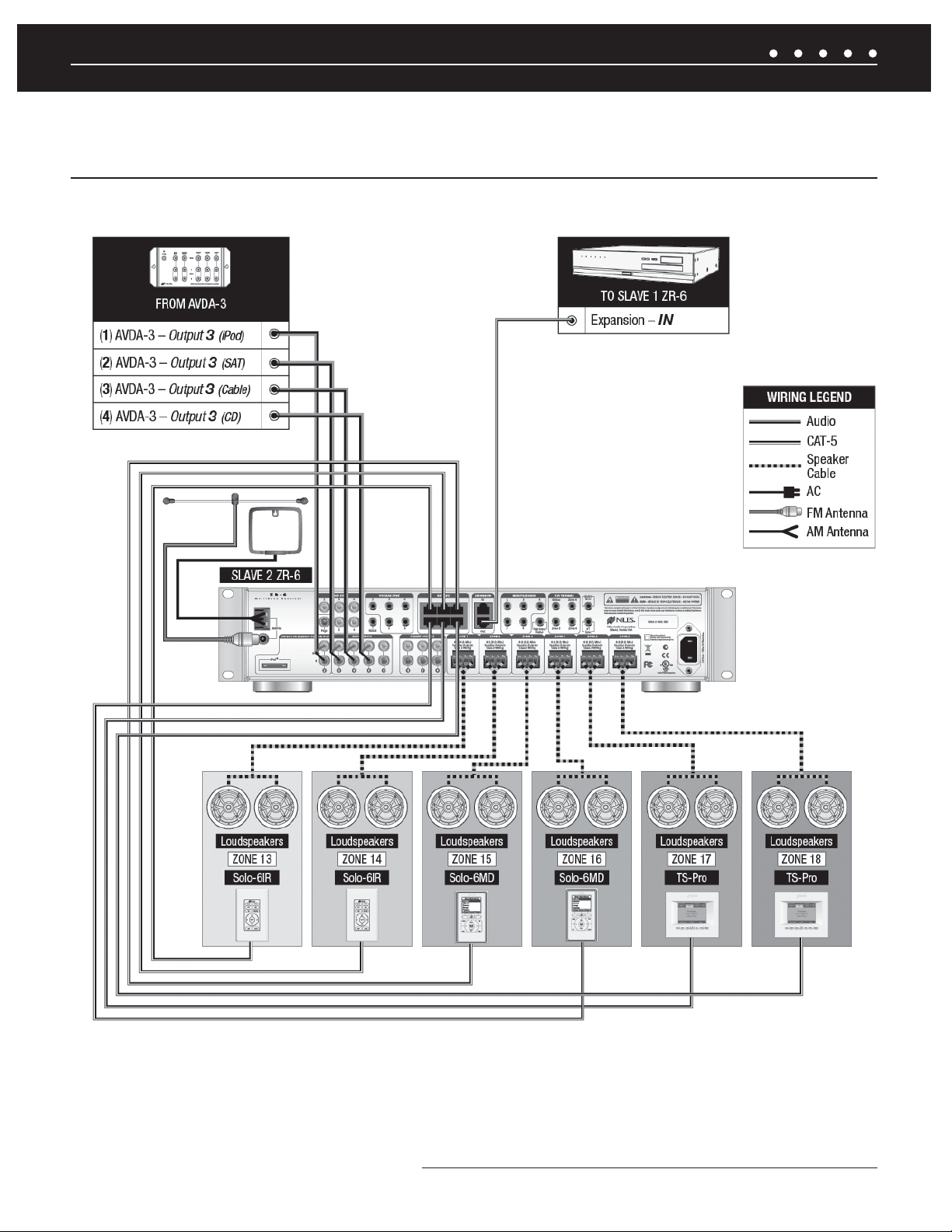
EXTERNAL CONTROL
All external IR or RS-232 controllers must be connected to the Master, and not the Slave(s). The control commands are routed to the
Slave(s) through the expansion ports.
NILES AUDIO CORPORATION – 1-800-BUY-HIFI – 305-238-437318
Page 21
SYSTEM WIRING DIAGRAMS
EXPANDING TO 18 ZONES WITH ADDITIONAL ZR-6 MULTIZONE RECEIVERS
Figures 5a, 5b, 5c
(CONTINUED ON NEXT PAGE)
19NILES AUDIO CORPORATION – 1-800-BUY-HIFI – 305-238-4373
Page 22
SYSTEM WIRING DIAGRAMS
EXPANDING TO 18 ZONES WITH ADDITIONAL ZR-6 MULTIZONE RECEIVERS
Figures 5a, 5b, 5c
Figure 5b. Expanding to 18 zones. Slave #1 ZR-6 detailed
NILES AUDIO CORPORATION – 1-800-BUY-HIFI – 305-238-437320
Page 23
SYSTEM WIRING DIAGRAMS
EXPANDING TO 18 ZONES WITH ADDITIONAL ZR-6 MULTIZONE RECEIVERS
Figures 5a, 5b, 5c
Figure 5c. Expanding to 18 zones. Slave #2 ZR-6 detailed
21NILES AUDIO CORPORATION – 1-800-BUY-HIFI – 305-238-4373
Page 24
SYSTEM WIRING DIAGRAMS
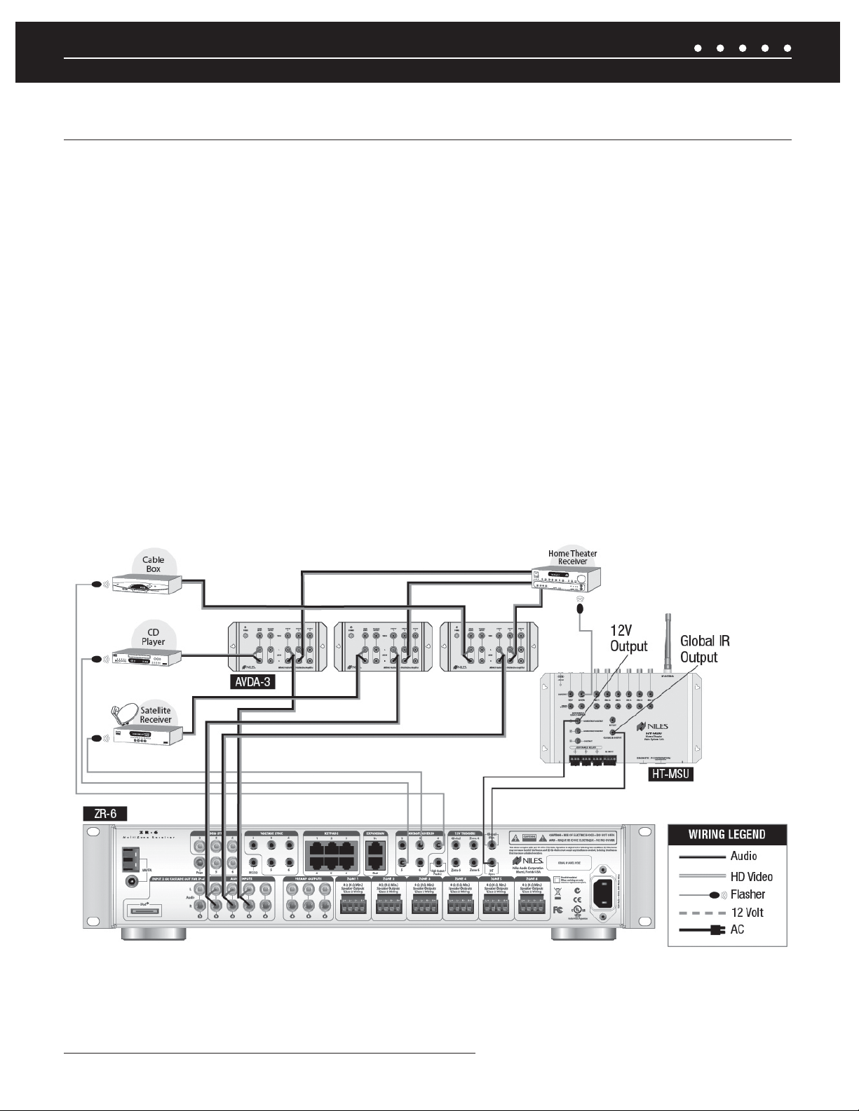
ZR-6 MULTIZONE RECEIVER INTEGRATED WITH A HOME THEATER SYSTEM
OVERVIEW
The ZR-6 MultiZone Receiver can share source devices with a home theater system.
IR CONTROL INPUT
The audio outputs of the source devices must be routed to both the ZR-6 MultiZone Receiver and the home theater receiver. This is best
accomplished using Niles AVDA-3 Source Level Stereo Audio/Video Distribution Amplifi ers (FG00814). Another method would be to use
RCA Y-adaptors to split the source device outputs in two, one to the ZR-6 MultiZone Receiver, the other to the home theater receiver.
SOURCE DEVICE CONTROL
IR MicroFlashers are attached to each source device and then connected to the ZR-6 MultiZone Receiver. To route the source device IR
commands from both the home theater controller and the ZR-6, an optional Niles HT-MSU Home Theater Main System Unit (FG01343) is
connected to the Global IR Control input of the ZR-6 MultiZone Receiver.
HOME THEATER SYNC
Connects from the HT Sync input to a 12V output on the Niles HT-MSU Home Theater Main System Unit to let the ZR-6 MultiZone Receiver
know when the home theater receiver is active. The ZR-6 MultiZone Receiver will not go into standby or turn off any source devices until all
of the zones are off and this voltage is eliminated.
Figure 6. Integrating with a home theater system
NILES AUDIO CORPORATION – 1-800-BUY-HIFI – 305-238-437322
Page 25
SYSTEM WIRING DIAGRAMS
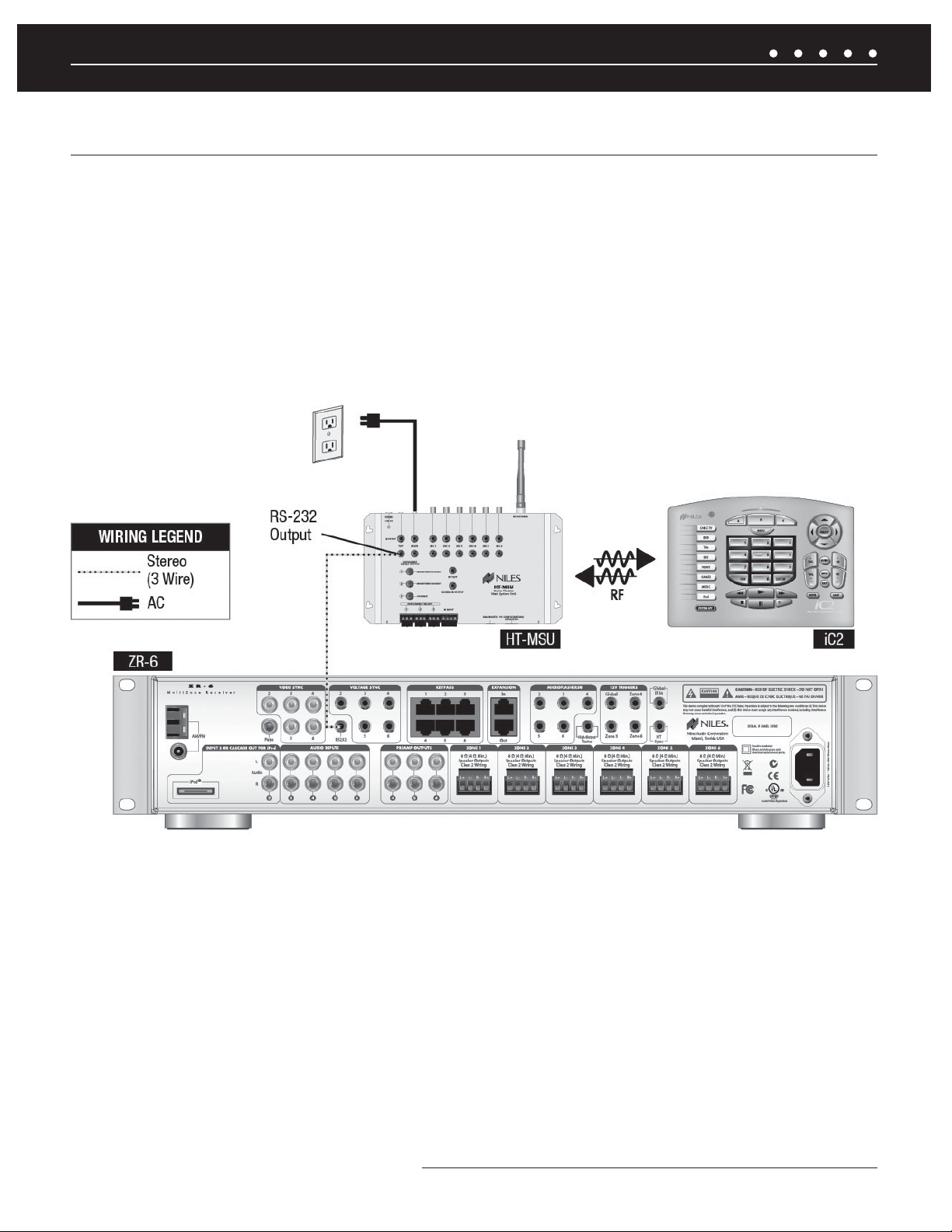
ADDING AN EXTERNAL RS-232 CONTROL SYSTEM TO THE ZR-6 MULTIZONE RECEIVER
OVERVIEW
The ZR-6 MultiZone Receiver can be integrated with an external control system that uses RS-232 serial communication.
RS-232 PORT
A 3.5 mm stereo mini-jack is used to provide RS-232 serial communication so the ZR-6 MultiZone Receiver can be monitored and
controlled by an external control system. Please refer to the Appendix for the RS-232 integration control protocols.
Figure 7. Connecting an external RS-232 control system
23NILES AUDIO CORPORATION – 1-800-BUY-HIFI – 305-238-4373
Page 26
SYSTEM WIRING DIAGRAMS
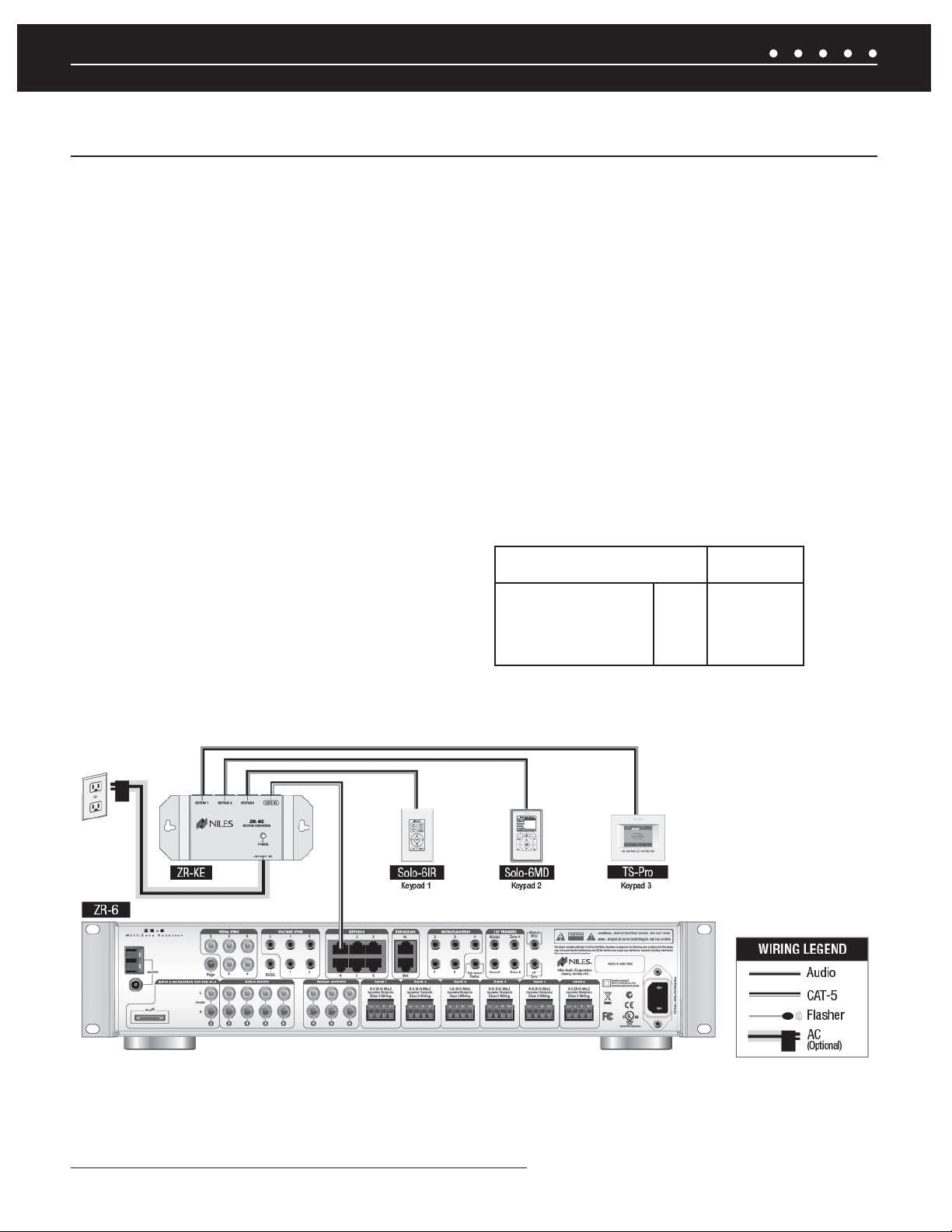
ADDING ADDITIONAL KEYPADS TO A ZONE
OVERVIEW
Any zone of the ZR-6 MultiZone Receiver can be expanded to contain up to three keypads. This is ideal for large rooms, bedrooms, and
outdoor applications.
NILES ZR-KE KEYPAD EXPANDER
The optional Niles ZR-KE Keypad Expander (FG01494) enables the use of up to three keypads per zone. An RJ-45 terminated CAT-5 cable
from a ZR-6 MultiZone Receiver keypad port is connected to the input of the ZR-KE. The three keypads are then connected to the outputs
of the ZR-KE using CAT-5 cable. One ZR-KE can be used for each zone, including any Slave zones when multiple ZR-6 MultiZone Receivers
are used to expand the number of system zones.
KEYPAD POWER VALUE (KPV)
When a large number of keypads are used in a system, additional power may be required to power the keypads. An optional power supply
(Niles 12VDC Universal Wall Adaptor FG01035) connects to the ZR-KE to supply this additional power, if necessary. To determine if the
keypads require additional power, calculate the keypad power value (KPV) by adding the point values of all keypads connected to each
chassis.
A single ZR-6 MultiZone Receiver Chassis will supply
power up to a total KPV of 30 points. Exceeding this
KPV will compromise operation of the MultiZone
Receiver and/or keypads.
CALCULATION TABLE
FOR KPV
Solo-6IR 1 point
NUMERIC-6P 1 point
Solo-6MD 3 points
TS-Pro 5 points
** Keypads connected to a ZR-KE keypad expander utilizing
an external power supply are not included in the KPV calculation.
ZR-6
POWERS UP TO
A TOTAL KPV OF
30 POINTS**
Figure 8. ZR-6 MultiZone Receiver with 3 keypads in zone
NILES AUDIO CORPORATION – 1-800-BUY-HIFI – 305-238-437324
Page 27
SYSTEM WIRING DIAGRAMS
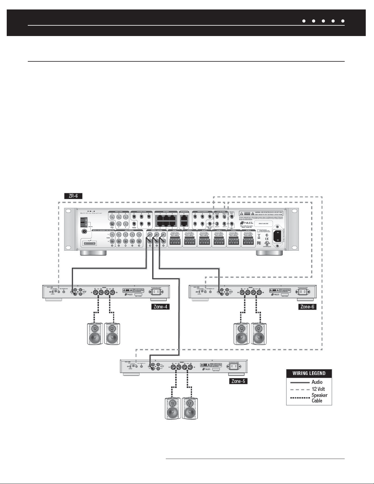
ADDING AN EXTERNAL AMPLIFIER T0 ZONE 4, 5 AND 6
OVERVIEW
The ZR-6 MultiZone Receiver is equipped with preamplifi er outputs for zones 4, 5, and 6 to connect external amplifi ers.
PREAMPLIFIER OUTPUTS
Zones 4, 5, and 6 have preamplifi er outputs used to connect an external power amplifi er. If an area is particularly large or requires a high
volume level, it is advised to assign it to zone 4, 5, or 6 and then connect an external amplifi er such as a Niles Systems Integration Amplifi er
to provide additional power to the loudspeakers. The preamplifi er outputs can be switched between a fi xed or variable level during system
setup.
12V TRIGGER OUTPUT
Zones 4, 5 and 6 each have a dedicated 12V Control Output that sends out a constant 12V DC voltage when the respective zone is active.
The Global 12V Control Output will send out a constant 12V DC trigger signal when any zone is active. These triggers can be used to
automatically switch on an amplifi er equipped with a 12V trigger turn-on, such as a Niles Systems Integration Amplifi er.
Figure 9. ZR-6 MultiZone Receiver with external amplifi ers in zones 4, 5, 6
25NILES AUDIO CORPORATION – 1-800-BUY-HIFI – 305-238-4373
Page 28
SYSTEM WIRING DIAGRAMS
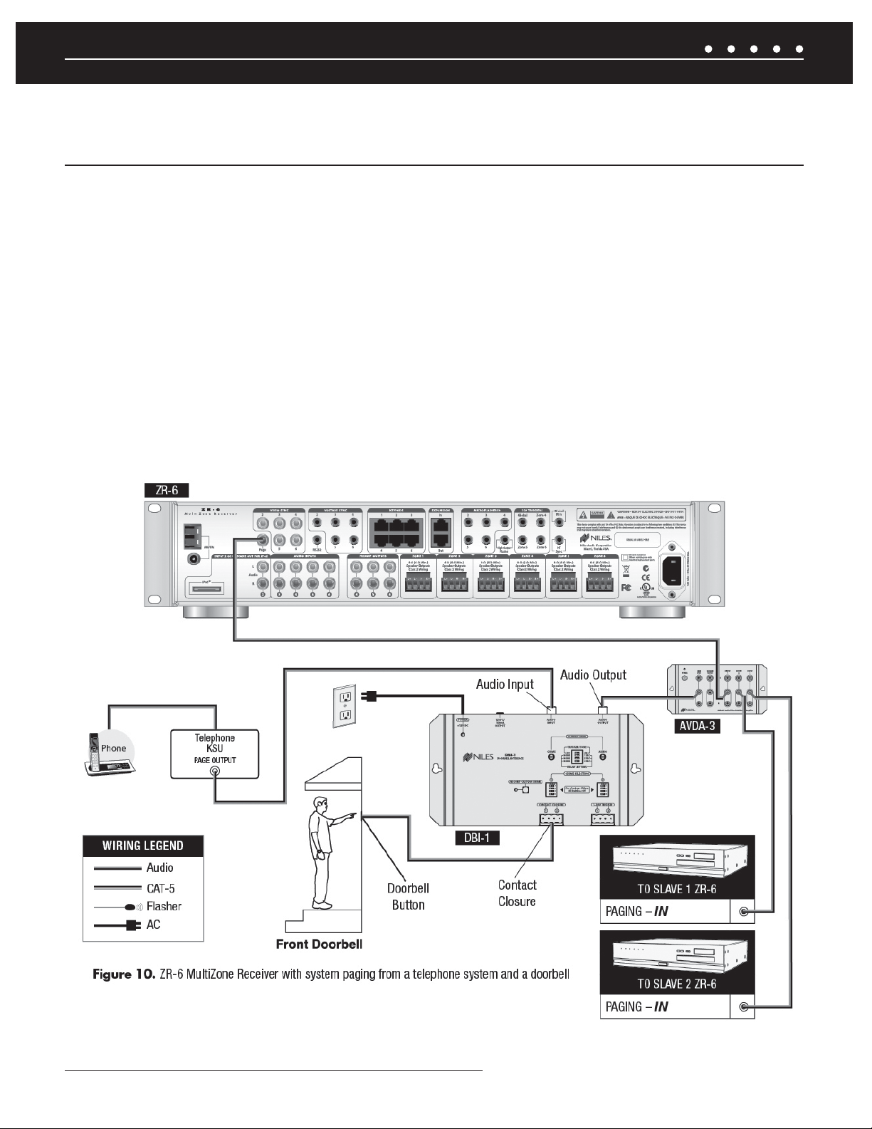
ADDING SYSTEM PAGING FROM EXTERNAL TELEPHONE SYSTEM,
INTERCOM SYSTEM AND/OR DOORBELL TO THE ZR-6 MULTIZONE RECEIVER
OVERVIEW
The ZR-6 MultiZone Receiver’s paging input provides an audio connection for voice paging and/or doorbell sounds to be played through the
system loudspeakers.
SYSTEM PAGING
The paging input senses the audio input level. When a signal appears, the volume level of the currently playing source device ramps down.
The paging audio signal then plays through the zone loudspeakers at a preset level. Zones can be enabled and disabled for paging in the
confi guration menu. By default, all zones are enabled for paging. A page will respond within one second. When the paging signal is removed
for at least fi ve seconds, the zone is switched back to the previous source device or, if the zone was previously off, it will turn off again.
DOORBELL PAGING
The optional Niles DBI-1 Doorbell Interface (FG01034) provides a selection of realistic doorbell chimes and includes connection for the
output from a telephone or intercom system. For more information, see the DBI-1 Installation & Operation Guide available for download at
www.nilesaudio.com.
NILES AUDIO CORPORATION – 1-800-BUY-HIFI – 305-238-437326
Page 29
SYSTEM INSTALLATION
ZR-6 MULTIZONE RECEIVER SYSTEM INSTALLATION
PREPARATION
Before you begin, make sure the audio cables, speaker cables, CAT-5 wiring, Niles MicroFlasher wires and the power supply cable are
of suffi cient length to reach the ZR-6 MultiZone Receiver. Label each cable describing where each cable originates (rather than to which
terminal on the ZR-6 it connects).
ATTACH THE RACK MOUNT EARS (IF NEEDED)
If the ZR-6 MultiZone Receiver is to be installed into a professional equipment rack, attach the supplied rack mount ears with the included
screws. The four non-slip plastic feet are removable, if necessary.
NOTE: USE ALL 4 SCREWS WHEN MOUNTING RACK EARS.
PLACEMENT OF THE ZR-6 MULTIZONE RECEIVER
Place the ZR-6 MultiZone Receiver on a fl at, level surface such as a table or shelf, with its weight equally distributed on each of its four
feet. Placing the weight of the receiver on the rear or front panel for even an instant may result in damage to the receiver’s connectors and
controls. Like any high-fi delity component, the ZR-6 MultiZone Receiver will last much longer if it is given adequate ventilation for proper
cooling. When installing the ZR-6 MultiZone Receiver in a cabinet, be sure that the rear of the cabinet is open to receive fresh air for proper
cooling. Place the ZR-6 MultiZone Receiver so it has 3.75” of air space above and at least 1” free space on either side. If multiple speaker
pairs are connected in more than one zone (creating a 4 ohm load in 2 or more zones), the minimum clearance above and below is 7” and
a Niles FM-1 (FG01215) or FM-1R (FG01214) System Cooling Module is required to maintain proper operating temperatures. If the receiver
is located on a carpeted surface, place a board under the receiver’s feet. Do not block the ventilation holes on the top or bottom. When
installed in a professional rack using the rack mounting ears, provide a minimum of 2 unit spaces above and below the ZR-6 MultiZone
Receiver, and a fan module immediately above the ZR-6 MultiZone Receiver.
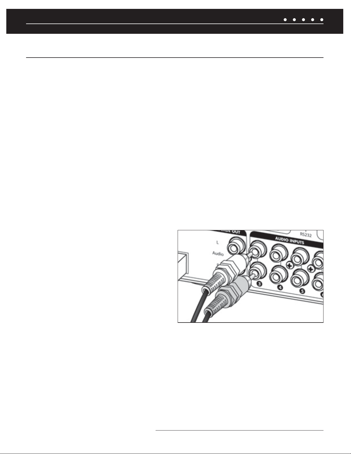
CONNECT THE AUDIO SOURCE DEVICES
Connect each source’s audio output cables to the corresponding
audio input connection of the ZR-6 MultiZone Receiver. When
making the connections, be sure that the audio cable’s two RCA
connectors are fully seated and that the proper color-code is
followed (white=left channel; red=right channel). The audio inputs
are labeled 2, 3, 4, 5 and 6 (Input 1 is the built-in AM/FM tuner).
When an iPod is used with the system, it is Input 2 and the analog
Source 2 input jacks become cascade audio outputs for the iPod
(Figure 11).
Figure 11. Proper connection of audio input cables
CONNECT THE iPod
Only USB host devices are supported fully. Other iPod types may not receive power and may not be charged while connected to the ZR-6
MultiZone Receiver. See the current iPod compatibility Matrix at www.nilesaudio.com. The supplied iPod connecting cable is labeled “iPod”
and “System”. Be certain to connect the cable in its proper orientation with the “System” label facing up when connected to the ZR-6
MultiZone Receiver and the “iPod” label facing the front of the iPod. The cable will only connect one way. Forcing it may cause damage.
CONNECT THE PAGING INPUT
The Page input on the rear panel of the ZR-6 MultiZone Receiver provides a connection for the paging out signal of telephone or intercom
systems for voice paging through the speakers in the listening zones (
Figure 10).
(CONTINUED ON NEXT PAGE)
27NILES AUDIO CORPORATION – 1-800-BUY-HIFI – 305-238-4373
Page 30
SYSTEM INSTALLATION
.*$30'-
3
O
Q
O
/
æ
ZR-6 MULTIZONE RECEIVER SYSTEM INSTALLATION
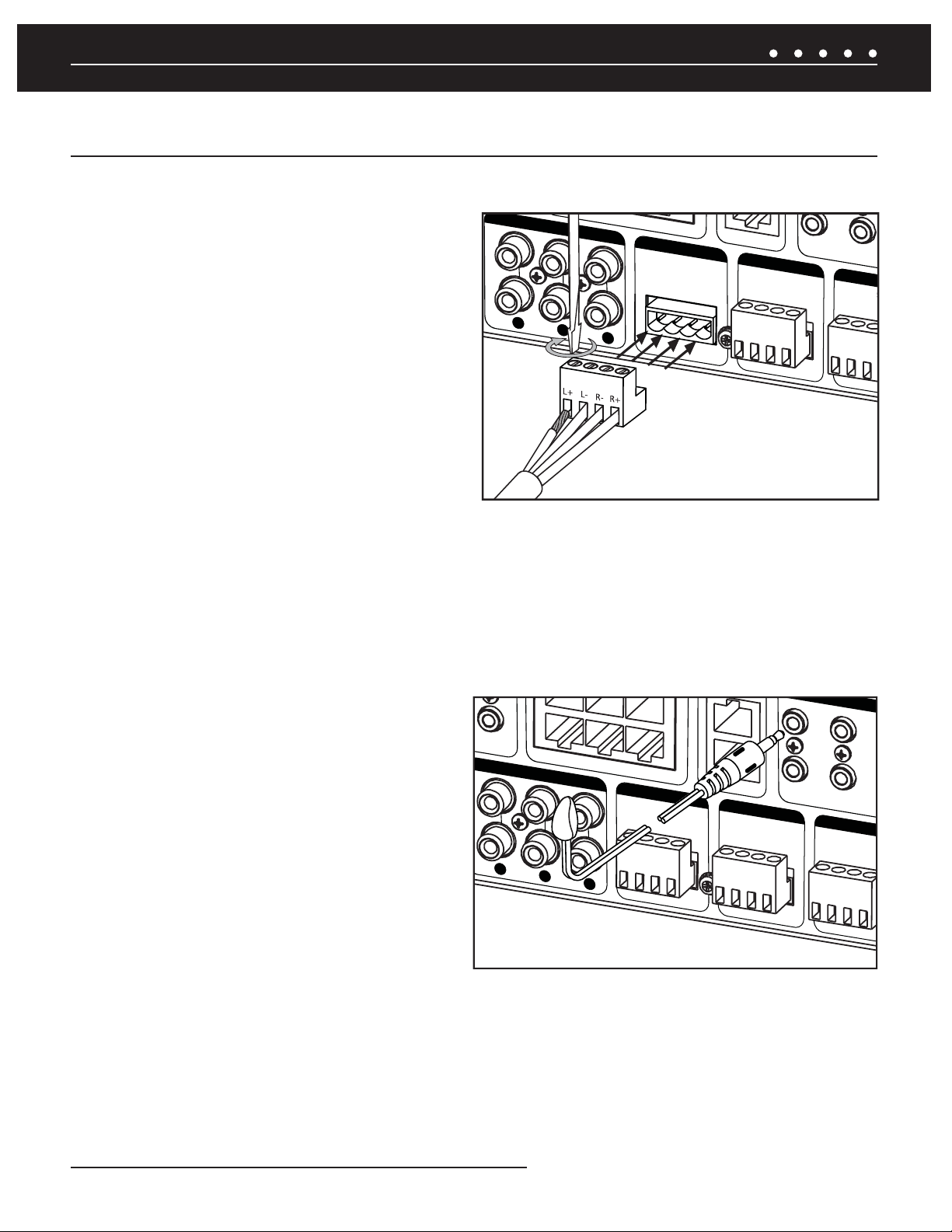
CONNECT THE LOUDSPEAKERS
CAUTION! ALL SPEAKER WIRE CONNECTIONS MUST BE MADE WITH THE
RECEIVER POWER OFF.
There are six sets of removable speaker wire terminals, one for each
zone. The terminals accept speaker wires up to 14 AWG in size.
Each terminal has four screw-down connections for speaker wire:
one positive (+) and one negative (-) for each speaker. Unscrew the
connection, insert the appropriate bare speaker wire, then tighten
fi r m l y
(Figure 12). Should a speaker output be shorted for some
reason, the power-on diagnostics routine in the ZR-6 MultiZone
Receiver will detect this short and display the specifi c output
experiencing the issue on the front panel LCD display. If a speaker
output is open, the amplifi er for that output is disabled by the poweron diagnostics. Should a speaker be connected later, the amplifi er
for that output will be enabled during the next power-on sequence.
13&".10651654
;0/&
ææ.JO
4QFBLFS0VUQVUT
$MBTT8JSJOH
0VU
;0/&
ææ.JO
4QFBLFS0VUQVUT
$MBTT8JSJOH
Figure 12. Connecting Loudspeakers to ZR-6
MultiZone Receiver
;0
æ
4QFBLFS
$MBTT
CONNECT THE EXTERNAL POWER AMPLIFIERS
If a zone is a particularly large area, or if high volume levels are required, it is suggested that Zones 4, 5, or 6 be augmented by an
additional stereo power amplifi er such as a Niles Systems Integration Amplifi er. The zone Preamplifi er outputs are selectable for variable
or fi xed output in the confi guration menu. The dedicated 12V output from each respective zone can be used to turn on the Systems
Integration Amplifi er power when the zone is active. The Global 12V output can be used to turn on the Systems Integration Amplifi e r ’ s
power when any zone is active.
CONNECT THE NILES IR MICROFLASHERS
Each Niles MicroFlasher (sold separately) connects into the
Flasher Outputs 2-6. The MicroFlasher portion is placed directly
over the IR sensor of the corresponding source component
(Source 2 for MicroFlasher 2, Source 3 for MicroFlasher 3, Source
4 for MicroFlasher 4, Source 5 for MicroFlasher 5, and Source
6 for MicroFlasher 6) and adheres with the included adhesive.
Remove the protective paper cover to expose the adhesive and
attach to the source component. A MicroFlasher is not used to
control the iPod. The iPod receives all control signals via the
30-pin connector cable.
NOTE: DO NOT CONNECT A MICROFLASHER TO THE HIGH OUTPUT
FLASHER PORT AS IT WILL DAMAGE THE MICROFLASHER.
;0/&
ææ.JO
4QFBLFS0VUQVUT
$MBTT8JSJOH
13&".10651654
Figure 13. Connecting IR Flashers to
ZR-6 MultiZone Receiver
0VU
;0/&
ææ.JO
4QFBLFS0VUQVUT
$MBTT8JSJOH
"4)&
;0/&
ææ.J
4QFBLFS0VU
$MBTT8JSJ
CONNECT A HIGH OUTPUT FLASHER
A Niles IRB-1 High Output Flasher (FG1023) is used to control multiple devices. The mini-plug end of the IRB-1 connects to the "High
Output Flasher" output on the ZR-6 (the ZR-6 is shipped with a red plastic plug blocking this jack to prevent accidental connection of a
MicroFlasher. Remove the red plastic insert by pulling it out from the jack). The IRB-1 should be positioned to provide IR transmission to all
source components.
NILES AUDIO CORPORATION – 1-800-BUY-HIFI – 305-238-437328
Page 31

SYSTEM INSTALLATION
INPUT 2 OR iPod CASCADE OUT
ZR-6 MULTIZONE RECEIVER SYSTEM INSTALLATION
CONNECT THE KEYPADS
Each keypad controls a specifi c zone (except TS-Pro). The RJ-45 terminated
CAT-5 cable that runs to each keypad is connected to the ZR-6 MultiZone
Receiver’s keypad ports labeled: Zone 1, Zone 2, Zone 3, Zone 4, Zone 5
and Zone 6. The zone port to which each keypad connects defi nes the zone
controlled by that keypad and the default zone for TS-Pro. For example: the
keypad connected to Zone 1 will always control Zone 1. All RJ-45 terminated
CAT-5 cables utilize the T568A wiring convention
(Figure 14).
CONNECT THE SLAVE ZR-6 MULTIZONE RECEIVER
Multiple ZR-6 MultiZone Receivers can be combined to create up to an
eighteen-zone system. The Expansion ports serially connect the multiple ZR-6
MultiZone Receivers with RJ-45 terminated CAT-5 cables using the T568A
wiring convention. One receiver must be designated as the Master, the others
as Slave(s). If more than one Slave is used, please note that the expansion out
of Slave 2 connects to the expansion in of Slave 1. The expansion out of Slave
1 then connects to the expansion in of the Master. Do not connect more than
one Slave directly to a Master. All MicroFlashers for source control must be
connected to the Master and not to the Slave, IR from the keypads connected
to the Slave will be routed to the Master via the expansion ports.
8= BROWN
7= BROWN/WHITE
6= ORANGE
5= BLUE/WHITE
4= BLUE
3= ORANGE/WHITE
2= GREEN
1= GREEN/WHITE
Figure 14. T568A wire termination
CONNECT THE AM AND FM ANTENNAS
FM DIPOLE ANTENNA
The included FM dipole antenna connects to the female 75-ohm
coaxial connector. The antenna is then positioned and mounted
for best reception. An antenna must be connected to each ZR-6
MultiZone Receiver chassis in Master/Slave confi gurations.
AM LOOP ANTENNA
The included AM loop antenna connects with its bare-wire ends
to the spring-loaded terminals. The antenna is then positioned and
mounted for best reception. An antenna must be connected to each
Figure 15. Connecting AM/FM Antennas to the ZR-6
MultiZone Receiver
ZR-6 MultiZone Receiver chassis in Master/Slave confi gurations.
CONNECT THE 12V OUTPUTS
The Global 12V output triggers an external device whenever any zone is active. The Zone 4, 5 and 6 12V outputs trigger an external device
whenever the respective zone becomes active. A common use would be to turn on a 12V trigger-equipped Niles Systems Integration
Amplifi er connected to the pre-amplifi er outputs. The 12V outputs can also be used to trigger a Niles AC-3 Voltage-Triggered AC Power
Strip (FG00242) to automate power turn-on and turn-off of connected sources.
(CONTINUED ON NEXT PAGE)
29NILES AUDIO CORPORATION – 1-800-BUY-HIFI – 305-238-4373
Page 32

SYSTEM INSTALLATION
ZR-6 MULTIZONE RECEIVER SYSTEM INSTALLATION
CONNECT THE HT (HOME THEATER) SYNC IF NEEDED
If the ZR-6 MultiZone Receiver Kit is going to share audio source components with a separate home theater system, it is important to use
the HT (home theater) sync. A voltage signal from the home theater receiver allows the ZR-6 MultiZone Receiver to know that the home
theater receiver is on and may be utilizing connected sources. The ZR-6 MultiZone Receiver will not go into standby, even if all of its zones
are shut off, until this voltage signal is no longer present. Use a 3.5 mm stereo plug (FG01019). One end connects to the HT Sync port on
the ZR-6 MultiZone Receiver, the other end to a trigger output (or similar) on the home theater receiver. If a trigger output is not available
on the home theater receiver, an alternate Niles CS12V Current Sensing 12V Trigger (FG01173) may be used. When the power cord of the
home theater receiver is connected to the current sensing outlet on the CS12V and the receiver is turned on, the CS12V sees the additional
current draw and sends out a 12V trigger.
CONNECT THE EXTERNAL CONTROLLER
The ZR-6 MultiZone Receiver can be externally controlled in two ways: RS-232 and/or IR.
RS-232
The ZR-6 MultiZone Receiver is equipped with two-way RS-232 serial
communication. This allows the receiver to be monitored and controlled by
an external control system such as the Niles iC2 (FG01342). The RS-232
port uses a 3.5 mm stereo jack with standard TRS (Tip, Ring, Sleeve)
confi guration of Transmit, Receive, and Ground
control command protocols for the ZR-6 MultiZone Receiver are located in
the
RS-232 Control Protocols
section.
(Figure 16). The RS-232
IR INPUT
The ZR-6 MultiZone Receiver can be controlled by a programmable/
learning IR remote control system. Connect a Niles IR sensor (several
models available separately) to receive the IR signals from the IR remote
control to the Global IR input. The discrete IR control codes for the ZR-6
MultiZone Receiver are available in several formats. See www.nilesaudio.
com/techsupport.
Sleeve
Ground
Figure 16. 3.5 mm Stereo Plug
Ring
Receive
Transmit
Tip
CONNECT THE MAIN POWER CABLE
The ZR-6 MultiZone Receiver is equipped with an IEC Cable Connector. A supplied, removable power cable is attached to this two-pin
Power Connector and then plugged into an AC wall outlet. This is the AC power disconnect for the ZR-6 MultiZone Receiver and should
remain accessible during use. A high quality surge suppression device is recommended to protect the equipment from potentially harmful
power surges and spikes.
NILES AUDIO CORPORATION – 1-800-BUY-HIFI – 305-238-437330
Page 33

SYSTEM INSTALLATION
KEYPAD INSTALLATION
GUIDELINES
The ZR-6 MultiZone receiver requires at least one Master Keypad (Solo-6IR, Solo-6MD, or TS-Pro) in each active listening zone. Up to three
Master Keypads can be installed in each zone using the optional ZR-KE Keypad expander (FG01494). The Numeric-6P Accessory Keypad
can be combined with the Solo-6IR to provide even more control.
The Solo-6IR, Solo-6MD, and Numeric-6P keypads are weather-resistant and may be used in damp or wet locations, but must be
installed in outlet boxes listed in accordance with the NEC and approved for this application. These keypads are weather-resistant from
the front face when the wall plate is sealed to the wall using a silicone bead or other waterproof sealant. If the inside of the wall is a
wet environment, it is recommended that all wiring utilize a drip loop to help prevent water from entering the back of the keypad. Do not
submerge the keypad. In freezing temperatures, the keypad’s IR sensor will have reduced range, but will return to normal when unfrozen.
Do not install the keypads in environments where the ambient temperature exceeds 100º C (212º F).
CHOOSE A MOUNTING LOCATION
Convenient keypad mounting locations include:
1. Near a doorway
2. Near a desk
3. At your bedside
4. Close to a telephone
5. Near other wall-mounted controls.
Keypad mounting considerations include:
1. Avoid direct sunlight
2. Accessibility for direct button operation
3. Line of sight for IR operation
4. Close to a telephone
5. Appropriate height for display visibility
6. Accessibility for wiring (if retrofit)
SOLO-6IR
The Solo-6IR comes in a kit that includes the keypad in white with a white faceplate. Also included are color change kits in light almond
and bone. Optional kits are available in black (FG01532) and silver (FG01570). The color change kit must be installed prior to installation in
the wall.
1. Gently compress the two retaining tabs at the top
of the Decora insert, then lift the top. Remove the
bottom of the Decora insert in the same manner. The
main buttons will come off with the Decora insert and
any installed Master Keys can now be easily removed.
2. To reinstall, snap the new Decora insert in place,
making certain that the attached buttons are seated
over the elastomer sub-buttons.
3. Do not install the Master Keys at this point. They
should be installed after the keypad has been
mounted in the wall.
4. Install the keypad into the wallbox using the two 6-32
screws provided.
5. Install the wall plate two mounting bracket using the screws provided.
6. Snap the trim plate into place.
7. Test the button action and adjust as necessary for consistent operation.
Solo-6IR Installation
(CONTINUED ON NEXT PAGE)
31NILES AUDIO CORPORATION – 1-800-BUY-HIFI – 305-238-4373
Page 34

SYSTEM INSTALLATION
KEYPAD INSTALLATION
INSTALL THE SOLO-6IR MASTER KEYS
Solo-6IR Keypads are shipped with the Master Keys uninstalled. 14 Master Keys are included (seven different labels for the left side, seven
different labels for the right side). To install the Master Keys:
1. Remove a Master Key from the “tree”. Note the difference between the left and right side versions. Be sure the keycaps break
off cleanly. Remove any excess plastic material.
2. Insert the Master Key in the appropriate hole over the elastomer until you can feel it “click” when it is pushed in.
3. Do not remove the Decora insert to install the Master Key Labels, the key caps snap in place through the Decora insert.
Press the supplied screwless wallplate into place, making sure the Decora inserts are centered in the openings and fl ush with the
wallplate. "Radio" is always top left (source 1). "iPod" is always top right (source 2).
SOLO-6MD
The Solo-6MD keypad kit includes the display keypad and faceplate kits in White, Bone and Light Almond. The faceplates have the button
caps attached.
1. Install the keypad mounting bracket with the two 6-32 screws provided. Be careful not to over tighten the screws and distort the
bracket.
2. Install the Solo-6MD keypad using the four 4-40 countersunk screws provided. DO NOT press on the display. Over-tightening these
screws can crack the bracket. They should be snug and fl ush with the surface.
3. Press the faceplate insert into place until it clicks. DO NOT press on the display. Check the operation of all the buttons and adjust as
necessary for consistent and easy operation.
4. Push the outside bezel into place, pressing snugly against the wall. When removing the bezel, slide a card (business card, driver's
license, etc.) in between the bezel and the faceplate to disengage the ratcheting hold-downs. The bezel will then lift off easily
without damage.
Solo-6MD Installation
NILES AUDIO CORPORATION – 1-800-BUY-HIFI – 305-238-437332
Page 35

SYSTEM INSTALLATION
KEYPAD INSTALLATION
NUMERIC-6P
The Numeric-6P comes in a kit that includes the keypad in white. A faceplate is not included. Included are color change kits in light almond
and bone. The color change kit must be installed prior to installation in the wall.
1. Gently compress the two retaining tabs at the top of the Decora insert, then lift the top. Remove the bottom of the Decora insert in the
same manner. The colored key caps will come off with the Decora insert.
2. To reinstall, snap the new Decora insert in place, making certain that the buttons are seated over the elastomer sub-buttons.
3. Test the button action and adjust as necessary for consistent operation.
CONNECT THE CAT-5 CABLE TO THE KEYPAD
Each keypad directly connects to the ZR-6 MultiZone Receiver by a “home run” of CAT-5 cable with RJ-45 connectors utilizing the T-568A
wiring convention (
to connect to the Solo-6IR Keypad.
FIGURE 14). The CAT-5 cable connects to the “System” jack on the back of the keypad. The Numeric-6P includes a cable
INSTALL THE KEYPADS INTO JUNCTION BOXES
The Solo-6IR and Solo-6MD Master Keypads mount into a standard single-gang in-wall junction box. If the Numeric-6P Accessory Keypad is
to be added to the Solo-6IR, a two-gang junction box and a two-gang Decora wallplate are necessary.
INSTALLING KEYPADS IN WET AREAS
The Solo-6IR and Solo-6MD keypad feature a true weather-resistant design, opening up the possibilities for installation in moist areas such as
bathrooms, saunas, or in covered outdoor areas like patios. However, in these applications special care must be taken to properly seal the front
of the keypad so moisture does not permeate the back of the keypad, which is not weather resistant. If the keypad is sealed properly, you can
expect consistent and long-lived operation in environments where normal keypads are simply not designed to function. To install the keypad in
a moist area, follow the normal installation procedure, but add these two very important steps:
1. Apply a bead of silicone to seal the faceplate to the wall. Be certain all gaps are fi lled and the seal is consistent.
2. Install the front bezel (Solo-6MD only) to cover the bead of silicone.
silicone bead
Install bezel to cover
silicone bead
33NILES AUDIO CORPORATION – 1-800-BUY-HIFI – 305-238-4373
Page 36

SYSTEM INSTALLATION
TOUCHSCREEN INSTALLATION
TS-PRO
Determine the best mounting location for the TS-Pro, taking into account the framing, electrical
wiring, fi xtures, and any mechanical limitations present in the stud space. Make sure the area behind
the TS-Pro is at least 3" deep and clear of any obstructions.
The TS-Pro touchscreen is designed to provide the best screen resolution when installed at a
mounting height of 60" on-center.
1. Use the supplied template to cut a hole in the wall. For new construction, a New Construction
Bracket (FG01603) is available.
2. Connect the wiring and then position the TS-Pro touchscreen in place. When lined up and
level, clamp the top and bottom dog-ears using the front panel screws.
3. Snap the faceplate in place.
RJ-45
Utility
Adapter
Keypad height installation
guideline.
60"
System
Connection
TS-PRO
New Construction
Bracket
Faceplate
ADDING AN EXTERNAL IR SENSOR TO A TS-PRO
To connect an external IR sensor, use the included RJ-45 utility adapter. Connect the external sensor as shown in the fi gure below.
White
Yellow
Data
Status
MS220
Red
12V+
Utility Adapter
Black
Ground
NILES AUDIO CORPORATION – 1-800-BUY-HIFI – 305-238-437334
Page 37

SYSTEM CONFIGURATION
CONFIGURING THE ZR-6 MULTIZONE RECEIVER
The Niles ZR-6 MultiZone Receiver is simple to confi gure using the
front panel buttons and LCD display. No computer is necessary.
NOTE: THE ZR-6, THE SLAVE ZR-6 (IF APPLICABLE), ALL SOURCE
DEVICES, KEYPADS AND SPEAKERS MUST BE CONNECTED PRIOR TO
PERFORMING ANY OF THESE OPERATIONS.
MAIN POWER
The ZR-6 MultiZone Receiver has a mechanical latching main
power switch on its front panel. The ZR-6 and its accessories will
not work until it has been engaged. Press in the Main Power switch
to the on position. It is illuminated with LEDs to indicate that it is on
and ready to operate.
ENTERING THE CONFIGURATION MODE
To enter confi guration mode, power down the ZR-6 MultiZone
Receiver(s) by disengaging the Main Power switch for fi ve seconds
and then power it up again while simultaneously holding down the
Band and Set buttons. Release the Band and Set buttons when
[RELEASE BUTTONS TO CONTINUE] appears on the display.
RELEASE BUTTONS
TO CONTINUE
SLAVE 1 SLAVE 2
On each Slave ZR-6 MultiZone Receiver, hold down the Band
and Set buttons to save the change. [RELEASE BUTTONS TO
CONTINUE] will appear on the display. The Slave ZR-6 MultiZone
Receiver(s) will return to the normal operating mode.
Paging Volume and Zone 4, 5, and 6 Preamp confi gurations must
be confi gured on each chassis (Master and all slaves connected).
When a chassis is named as Slave 1 or Slave 2, only these items
will appear in the confi guration menu.
All other confi guration settings will be performed on the
Master ZR-6 MultiZone Receiver only.
To continue to the fi rst confi guration step on the Master ZR-6
MultiZone Receiver,
Zone Linking
, press the Set button once.
To save the settings and exit the confi guration mode, hold down the
Band and Set buttons. After the Master ZR-6 MultiZone Receiver
saves the settings [RELEASE BUTTONS TO CONTINUE] appears
on the display. The Master ZR-6 MultiZone Receiver will return to
the normal operating mode.
[MASTER] will be on the display. If there are multiple
ZR-6 MultiZone Receivers, repeat the above step on each unit.
[MASTER] will appear on the display of all units.
MASTER
MASTER/SLAVE
When a ZR-6 system is expanded to include more zones (up to
18 zones with three receivers), each chassis must have a unique
name: Master, Slave 1, or Slave 2. There can only be one Master
MultiZone Receiver.
When a second ZR-6 MultiZone Receiver is used as a Slave, press
the Band button once. [MASTER] will change to [SLAVE 1]. If
there is a third ZR-6 MultiZone Receiver that is used as a Slave,
pressing the Band button one more time changes the display to
[SLAVE 2] for that unit.
TECH TIP
All external IR and RS-232 control connections
must be made to the Master ZR-6 MultiZone
Receiver, and not to the Slave(s). The commands
used to control the Slave(s) are relayed through the
Expansion Ports. All MicroFlashers for source device control must be
connected to the Master ZR-6 MultiZone Receiver, and not the Slave(s).
IR from the keypads to the Slave(s) is routed to the Master through the
Expansion Ports
ZONE LINKING
This feature allows two or more zones to always play the same
source at the same time. Volume, bass, treble, and mute functions
will remain independent for each zone.
NOTE: ONLY ONE ZONE LINKING GROUP MAY BE CREATED PER CHASSIS
(ONE FOR THE MASTER, ONE FOR EACH OF THE SLAVES).
While in the confi guration mode (see above), press the Set button
until [123456 LINKING MASTER] shows in the display.
123456
LINKING
MASTER
35NILES AUDIO CORPORATION – 1-800-BUY-HIFI – 305-238-4373
Page 38

SYSTEM CONFIGURATION
CONFIGURING THE ZR-6 MULTIZONE RECEIVER
The numbers represent the 6 zones of the ZR-6 MultiZone Receiver.
A cursor will be blinking under the number“1” or "Zone 1."
Press the + button and the - button to toggle the cursor between
the zones. The cursor blinks under the zone number when it is
highlighted. Press the Band button to toggle “Y” on or off in the
highlighted zone. Zones with “Y” present will be linked.
123456YYLINKING
MASTER
NOTE: IN THIS EXAMPLE ZONES 1 AND 2 ON THE MASTER ARE LINKED.
After “6” on the Master, it will toggle back to “1” on the fi rst
connected Slave. After “6” on the last connected Slave, it will toggle
back to “1” on the Master.
Repeat these steps until all of the desired zones have been linked.
123456
YYYY
LINKING
SLAVE 1
Press the Band button to toggle the “Y” on or off in the highlighted
zone. Paging is enabled in all zones with a “Y”
123456
Y Y Y
NOTE: IN THIS EXAMPLE ZONES 1, 3 AND 5 HAVE PAGING ENABLED.
PAGE
MASTER
After “6” on the Master, it will toggle to “1” on the fi rst connected
Slave. After “6” on the last connected Slave, it will toggle back to
“1” on the Master.
Repeat these steps until all of the desired zones have been set for
the desired paging operation.
To continue to the next system confi guration step,
House Mode
, press the Set button once.
Party or Whole
To save the settings and exit the confi guration mode, simultaneously
hold down the Band and Set buttons. After the ZR-6 saves the
information, [RELEASE BUTTONS TO CONTINUE] appears on the
display. The ZR-6 will return to the normal operating mode.
To continue to the next system confi guration step,
Paging
, press
the Set button once. To save the settings and exit the confi guration
mode, simultaneously hold down the Band and Set buttons.
After the ZR-6 saves the information, [RELEASE BUTTONS TO
CONTINUE] appears on the display. The ZR-6 will return to the
normal operating mode.
PAGING
By default, all zones are enabled for paging (Figure 10). If there
are zones where the end-user does not want to hear a page, follow
these steps.
While in the confi guration mode (see above), press the Set button
until [123456 PAGE MASTER] shows in the display. A “Y” appears
below every zone number. A cursor will be blinking under the
number “1” or "Zone 1."
123456
YYYYYY
Press the + button or - button to toggle the cursor between the zones.
The cursor under the zone number blinks when a zone is highlighted.
PAGE
MASTER
PARTY OR WHOLE HOUSE MODE
This feature lets the end-user press-and-hold any Source
Selection button for three seconds to turn on the entire house
to the same source for a party. It also allows for the press-andhold of the Off button to turn off the entire system from one
zone keypad without the need to walk around to every keypad to
do so. By default all zones will respond to Party mode. If there
are zones that the end-user does not want to turn on when a
press-and-hold is initiated, follow these steps.
NOTE: THIS FEATURE ONLY DEACTIVATES THE PRESS-AND-HOLD TURNON AND NOT THE TURN-OFF. THE PRESS-AND-HOLD TURN-OFF
IS ALWAYS AVAILABLE AT ANY KEYPAD REGARDLESS OF THIS SETTING.
While in the confi guration mode (see above), press the Set
button until [123456 PARTY MASTER] shows in the display.
The numbers represent the 6 zones of the ZR-6 MultiZone
Receiver. A cursor will be blinking under the number “1” or
"Zone 1."
123456
YYY YY
PARTY
MASTER
(CONTINUED ON NEXT PAGE)
NILES AUDIO CORPORATION – 1-800-BUY-HIFI – 305-238-437336
Page 39

SYSTEM CONFIGURATION
CONFIGURING THE ZR-6 MULTIZONE RECEIVER
Press the + button or - button to toggle the cursor between the
zones . A “Y” appears under every zone number. The cursor
under the zone number blinks when a zone is highlighted.
Press the Band button to toggle the “Y” on or off in the
highlighted zone. Only zones with a “Y” will respond to whole
house turn on.
123456
YYY
NOTE: IN THIS EXAMPLE ZONES 1, 2 AND 3 ARE CONFIGURED FOR
PARTY MODE.
PARTY
MASTER
After “6” on the Master, it will toggle to “1” on the fi rst
connected Slave. After “6” on the last connected Slave, it will
toggle back to “1” on the Master.
Repeat these steps until all of the desired zones have been set for
the desired Party mode operation.
To continue to the next system confi guration step,
VOLUME
, press the Set button once.
PAGE MODE
To save the settings and exit the confi guration mode,
simultaneously hold down the Band and Set buttons. After the
ZR-6 saves the information, [RELEASE BUTTONS TO CONTINUE]
appears on the display. The ZR-6 will return to the normal operating
mode.
PAGE MODE VOLUME
The paging volume level for the selected zones is adjustable.
Paging level must be set on each slave as well as the master.
Since the paging volume level will be the same for all zones
connected to that chassis, we suggest setting a comfortable
level in the room that will be used most frequently, or in the
smallest room. While in the confi guration mode (see above), press
the Set button until [PAGE MODE VOLUME = XX] shows in
the display.
PAGE MODE
VOLUME = 60
PAGE MODE
VOLUME = 34
To continue to the next system confi guration step,
Zone 4 Pre-Out
press the Set button once.
To save the settings and exit the confi guration mode,
simultaneously hold down the Band and Set buttons. After the
ZR-6 saves the information, [RELEASE BUTTONS TO CONTINUE]
appears on the display. The ZR-6 will return to the normal operating
mode.
MAXIMUM VOLUME LEVEL
A Maximum Volume Level can be confi gured for each zone. The
volume level in zone will never exceed this Maximum level. The
default maximum volume level in a zone is 100%. When the
volume in a zone is at the maximum level, the volume bar indicator
on the keypad or touch panel shall indicate 100%.
While in the confi guration Menu, press SET until [SET MAX
VOLUME] is displayed.
SET MAX VOLUME
-/NO + /YES
Press + to confi gure Maximum Volume levels for each zone. [ZONE
1 MAX VOLUME] will appear on the display. Press the – button
to move to the next confi guration step without setting maximum
volume levels.
ZONE 1 MAX VOLUME
VOLUME= 90MASTER
Press + to raise the volume and press – to lower the volume. Press
SET to save the maximum volume setting and move to the next
step. After Zone 6 on the Master, Zone 1 on Slave 1 (if connected)
will be displayed. After Zone 6 on Slave 2 (if connected), the
confi guration menu will move to Zone 4 Pre out on the Master
,
Press the + button to increase the paging volume. Press the - key
to decrease the paging volume. The factory default setting is 60.
The volume range is from 0 to 99.
ZONE 2 MAX VOLUME
VOLUME=100MASTER
37NILES AUDIO CORPORATION – 1-800-BUY-HIFI – 305-238-4373
Page 40

SYSTEM CONFIGURATION
CONFIGURING THE ZR-6 MULTIZONE RECEIVER
ZONE 4 PRE-OUT
The ZR-6 MultiZone Receiver is equipped with Zone 4 pre-amplifi er
outputs that enable the use of a separate outboard power amplifi er.
This must be confi gured on each slave as well as the master.
While in the confi guration mode (see above), press the Set
button until the display shows [ZONE 4 PRE-OUT VARIABLE].
The default setting is for the preamplifi er outputs to be variable (the
output level is controlled by the ZR-6 volume control).
ZONE 4 PREOUT
VARIABLE
To change these outputs to a fi xed volume level, press the Band
button. The display will show [PRE-OUT 4 FIXED]. The Zone 4
Output is now set to +6dB relative to the selected source device
input level.
ZONE 4 PREOUT
FIXED
ZONE 5 PRE-OUT
The ZR-6 MultiZone Receiver is equipped with Zone 5 pre-amplifi er
outputs that enable the use of a separate outboard power amplifi er.
This must be confi gured on each slave as well as the master.
While in the confi guration mode (see above), press the Set
button until the display shows [ZONE 5 PRE-OUT VARIABLE].
The default setting is for the preamplifi er outputs to be variable
(controlled by the ZR-6 volume control).
ZONE 5 PREOUT
VARIABLE
To change these outputs to a fi xed volume level, press the Band
key. The display will show [PRE-OUT 5 FIXED]. The Zone 5 Output
is now set to +6dB relative to the selected source input level .
ZONE 5 PREOUT
FIXED
To continue to the next system confi guration step, Zone 5 Pre-Out,
press the Set button once.
To save the settings and exit the confi guration mode,
simultaneously hold down the Band and Set buttons. After the
ZR-6 saves the information. [RELEASE BUTTONS TO CONTINUE]
appears on the display. The ZR-6 will return to the normal operating
mode.
To continue to the next system confi guration step,
Zone 6 Pre-Out
press the Set button once.
To save the settings and exit the confi guration mode,
simultaneously hold down the Band and Set buttons. After the
ZR-6 saves the information, [RELEASE BUTTONS TO CONTINUE]
appears on the display. The ZR-6 will return to the normal operating
mode.
ZONE 6 PRE-OUT
The ZR-6 MultiZone Receiver is equipped with Zone 6 pre-amplifi er
outputs that enable the use of a separate outboard power amplifi er.
This must be confi gured on each slave as well as the master.
While in the confi guration mode (see above), press the Set button
until the display shows [ZONE 6 PRE-OUT VARIABLE]. The default
setting is for the preamplifi er outputs to be variable (controlled by
the ZR-6 volume control).
ZONE 6 PREOUT
VARIABLE
,
(CONTINUED ON NEXT PAGE)
NILES AUDIO CORPORATION – 1-800-BUY-HIFI – 305-238-437338
Page 41

SYSTEM CONFIGURATION
CONFIGURING THE ZR-6 MULTIZONE RECEIVER
To change these outputs to a fi xed volume level, press the Band
button. The display will show [PRE-OUT 6 FIXED]. The Zone 6
Output is now set to +6dB relative to the selected source input level.
ZONE 6 PREOUT
FIXED
To continue to NAMING THE SOURCE DEVICES, press the Set
button once.
To save the settings and exit the confi guration mode, simultaneously
hold down the Band and Set buttons. After the ZR-6 saves the
information, [RELEASE BUTTONS TO CONTINUE] appears on the
display. The ZR-6 will return to the normal operating mode.
NAMING THE SOURCE DEVICES
While in the confi guration mode, press the Set button until the
display shows [SRC NAME]. Press the Set button to highlight
a source number. The numbers indicate the six sources of the
ZR-6 MultiZone Receiver. You cannot re-name Source 1 because it
is always the built-in AM/FM tuner. The default name for Source 2
is iPod.
SRC NAME3456
IPOD
in alphabetical order, except N/A which appears fi rst, and iPod
which appears fi rst for Source 2 only.
Available source device names:
Radio (default Source 1) iPod (default Source 2)
• N/A
• Blu-ray
• Cable
• Cable 2
• Cable 3
• CD
• CD 2
• CD 3
• CD Ch
• CD Ch 2
• CD Ch 3
• DMS
• DMS 2
• DMS 3
• DMS 4
• DVD
• DVD 2
• DVD Ch
• DVD Ch 2
• DVR
• HDTV
• MP3
• Music
• Music 2
• PC
• SAT Radio
• SAT Radio 2
• SAT Radio 3
• SAT TV
• SAT TV 2
• SAT TV 3
• TV
• TV 2
• Video
• Video 2
• Game
The corresponding Solo-6MD Master Keypad screen displays and
the TS-Pro device screens are shown in an appendix at the end of
this document.
To continue to the next confi guration step, ERASING TUNER PRESET
INFORMATION, press the Set button.
To save the settings and exit confi guration mode, simultaneously
hold down the Band and Set buttons. After the ZR-6 saves the
information, [RELEASE BUTTONS TO CONTINUE] appears on the
display. The ZR-6 will return to the normal operating mode.
If an iPod will not be used with the system, select a name for
the source device 2. If iPod remains as the Source 2 name
and no iPod is connected, whenever Source 2 is chosen [IPOD
DISCONNECTED] will appear on the screen.
With a source number highlighted, toggle through the available
source device names by pressing the + and – buttons.
SRC NAME2 456
SAT RADIO
The source device name that is selected is the name that will
appear on the LCD displays of Solo-6MD Master Keypads whenever
that source is selected and on the source keys of a
TS-Pro. There are 35 source device names available. They appear
ERASING TUNER PRESET INFORMATION
While in confi guration mode, press the Set button until the display
shows [ERASE PRESETS?]
ERASE PRESETS?
-/NO +/YES
Press + to erase all 20 tuner presets stored into the ZR-6. The
display will show [PRESETS ERASED].
PRESETS ERASED
39NILES AUDIO CORPORATION – 1-800-BUY-HIFI – 305-238-4373
Page 42

IR PROGRAMMING
PROGRAMMING SOURCE DEVICE IR COMMAND CODES
Press the – button to exit and move to the next step without erasing
any of the presets.
To continue to the next confi guration step, RESTORING FACTORY
DEFAULTS, press the Set button.
To save the settings and exit confi guration mode, simultaneously
hold down the Band and Set buttons. After the ZR-6 saves the
information, [RELEASE BUTTONS TO CONTINUE] appears on the
display. The ZR-6 will return to the normal operating mode.
RESTORING THE FACTORY DEFAULTS
While in confi guration mode, press the Set button until
[FACTORY RESET] appears on the display.
FACTORY RESET
-/NO +/YES
Press + to erase all confi guration data. All Master/Slave, zone
linking, paging, party mode, bass, treble, and loudness settings will
return to the factory default. NOTE: Learned IR commands will not
be erased. The display will show [CONFIRM ERASE].
CONFIRM ERASE
-/NO +/YES
Press the + button to confi rm the erase procedure. The display will
show [MASTER DEFAULT RESTORED].
OVERVIEW
By default, the connected keypads and the R-8L hand-held remote
will control source selection, AM/FM tuner functions, iPod functions,
zone volume level, and on/off for the zone and system. To enable
full control of any other connected source devices, the IR command
codes for these source devices must be learned and stored in the
ZR-6 MultiZone Receiver. The keypads and R-8L hand-held remote
will then control the source devices by sending the IR command
codes stored in the ZR-6 MultiZone Receiver through MicroFlashers
attached to the source devices.
HOW IR COMMAND CODES ARE ENTERED
AND STORED
The source device IR command codes are entered in the ZR-6
MultiZone Receiver using the source device factory remote controls.
The ZR-6 supplies each source device with a memory page to store
its IR command codes. The individual command codes (Play, Pause,
etc.) are stored in memory cells within each page, pre-labeled to
match the commands available on the R-8L remote control.
LIBRARY 1 AND VS-6/LIBRARY 2
In addition to the fi ve source device IR storage pages, the ZR-6
MultiZone Receiver provides two additional areas to store IR
command codes: Library 1 or the VS-6/Library 2. The Libraries
are typically used to store the IR command codes from non-source
devices such as draperies, television lifts, or other codes that the
installer prefers to be easily accessible. By default, Library 1 is
empty and Library 2 is fi lled with the IR command codes for the
Niles VS-6 Component High Defi nition Video Switcher (see VS-6
IR Command Set section). If a VS-6 is not being used, new IR
command codes can be learned in place of these.
MASTER
DEFAULT RESTORED
Press the – button (at either screen) to exit and move to the next
step without erasing any information.
To continue to the fi rst confi guration step, MASTER/SLAVE, press
the Set button.
To save the settings and exit confi guration mode, simultaneously
hold down the Band and Set buttons. After the ZR-6 saves the
information, [RELEASE BUTTONS TO CONTINUE] appears on the
display. The ZR-6 will return to the normal operating mode .
IR COMMAND CODE PROGRAMMING PROCEDURE
The source device IR command code programming is organized into
source device memory pages, and then command code memory
cells within the memory pages.
The source device memory pages appear in this order:
Page 1 Source 2 (Only if a source name other than
“iPod or “N/A’ was specifi ed in “Naming
Source Devices”
Page 2 Source 3
Page 3 Source 4
(CONTINUED ON NEXT PAGE)
NILES AUDIO CORPORATION – 1-800-BUY-HIFI – 305-238-437340
Page 43

IR PROGRAMMING
PROGRAMMING SOURCE DEVICE IR COMMAND CODES
Page 4 Source 5
Page 5 Source 6
Page 6 Library 1
Page 7 Library 2
Additional pages are supplied for building IR
command sequences:
Page 8 Tuner
Page 9 Source 2 (iPod)
Page 10 Source 3
Page 11 Source 4
Page 12 Source 5
Page 13 Source 6
The command code memory cells appear
in this order. (All codes are mapped to
correspondingly named buttons on the R-8L
remote). Please refer to the IR Mapping Chart
to determine which codes are activated by
button presses on the keypads.
Power ON
Power OFF
Play
Pause
Stop
Fast Forward
Rewind
Record
Next (
Previous (
Up
Down
Left
Right
OK (select)
#1
#2
#3
#4
#5
#6
on MD Keypad)
>
on MD Keypad)
<
#7
#8
#9
#0
Enter
Channel Up
Channel Down
Last
Menu
Guide
Info
List
Exit
Red
Green
Yellow
Blue
Input
Replay
Disc
Page Up
Page Down
Live
Fav
Random
Group
The command list is looped so that pressing
Previous with “Power ON” in the display
moves to “Group”.
CONSIDERATIONS:
• All zones should be off before entering
programming mode.
• It is not necessary to learn all devices,
or all commands for any device.
• Pages for devices not named in the
“Source Naming” confi guration will
not appear when learning IR codes.
• Pressing the Program button at any
time will move to the next memory
page (source device, library or
sequence). Any commands stored on
that page will be saved before moving
to the next page.
• Pressing the Previous and Next (or the
+ and -) buttons move through the
options within a memory page.
• Pressing-and-holding the
Program button at any time while
in programming mode will exit
programming mode. Any commands
stored prior will be saved.
• The source device factory remote
controls must be in working order and
have fresh batteries in order to learn
IR codes properly.
• The learning capacity for each
memory page (source, or library) is
approximately 42 to 75 commands,
depending on the complexity of the
commands being learned
• Certain device functions cannot be
learned, including multi-frequency
codes, some high frequency codes
and other unusual formats. An “IR
INVALID” message will appear on the
display should one of these codes be
encountered.
• For best results, avoid high levels of
ambient light, such as natural sunlight
or fl uorescent lighting.
• For future reference, it is
recommended that the learned IR
command information be recorded on
the forms provided in the Appendix.
• TS-Pro will disable any buttons for
which no IR command is present.
They will appear grayed out on the
screen.
41NILES AUDIO CORPORATION – 1-800-BUY-HIFI – 305-238-4373
Page 44

IR PROGRAMMING
PROGRAMMING SOLO-6MD AND SOLO-6IR COMMAND CODE MAPPING CHART
The MD Keypad function/buttons will
issue the IR commands learned in the
following location:
Solo-6MD
Keypad
Buttons
OFF OFF POWER OFF OFF STOP
Select Select PLAY 0x11
Select Select PAUSE 0x13
VOL + Vol + UP 0x17 (UP)
VOL – Vol – DOWN 0x1d (DOWN)
1#10x21 X X
2#20x22 X X
3#30x23 X X
4#40x24 X X
5#50x25 X X
6#60x26 X X
7#70x27 X X
8#80x28 X X
9#90x29 X X
0#00x2a X X
MENU MENU 0x16 X
REPEAT REPLAY 0x3a X X
SHUFFLE RANDOM 0x2d X X X
>
>
Solo-6IR
Keypad
Buttons
ZR-6 IR
Command
Label
POWER ON 0x31
OK 0x1e
NEXT 0x2c SEEK UP X X X
CHANNEL UP
PREVIOUS 0x2b SEEK DOWN X X X
CHANNEL DOWN
>
>
LEFT 0x19
RIGHT 0x1b
ENTER 0x45
LAST 0x91
GUIDE 0x18
INFO 0x1e
LIST 0x74
EXIT 0x1c
RED 0xba
GREEN 0xbb
YELLOW 0xbc
BLUE 0x76
INPUT 0x9a
DISC 0x2f
PAGE UP 0x7e
PAGE DOWN 0x7f
LIVE 0x39
FAV 0x30
GROUP 0x2e
HEX Code Radio iPod
INTERNAL DEVICES
AM/FM
PLAY/PAUSE
CD
CD 2
CD 3
CD Ch
CD Ch 2
CD Ch 3
NILES AUDIO CORPORATION – 1-800-BUY-HIFI – 305-238-437342
Page 45

IR PROGRAMMING
PROGRAMMING SOLO-6MD AND SOLO-6IR COMMAND CODE MAPPING CHART
DEVICE CODE BUTTON ON KEYPAD
DVD
DVD 2
Blu-Ray
DVD Ch
DVD Ch 2
DVR
SAT TV
SAT TV 2
SAT TV 3
Cable
Cable 2
Cable 3
Video
Video 2
TV
TV 2
HDTV
MP3
Music
Music 2
Power On issued for each device when selected; Power OFF issued for each device after a delay when no longer playing in any zone.
XX XX X X X
XX X X
XX XX X X X
XX X X
DMS
DMS 2
DMS 3
DMS 4
PC Game
X
Sat Radio,
Sat Radio 2
XXXXXX X
XXXXXX X
XXXXXX X
XXXXXX X
XXXXXX X
XXXXXX X
XXXXXX X
XXXXXX X
XXXXXX X
XXXXXX X
X XX X X
X XX X X
43NILES AUDIO CORPORATION – 1-800-BUY-HIFI – 305-238-4373
Page 46

IR PROGRAMMING
o
iPod
OFFSTOPP
USE
356
890
er
S
e
p
S
ee
Ma
u
SHU
E
PROGRAMMING TS-PRO COMMAND CODE MAPPING CHART
The TS-Pro Touchscreen function/
buttons will issue the IR commands
learned in the following location:
P = Button appears on the Primary (Main)
screen for that device.
S = Button appears on the Secondary screen
for that device.
T = Button appears on the Tertiary (Third)
screen for that device.
H = Command is mapped to a Hard Button
just below the screen.
TS-Pro
Buttons
OFF POWER OFF OFF STOP
OK OK 0x1e AM/FM
1#10x21 1 S
2#20x22 2 S
3#30x23 3 S
4#40x24 4 S
5#50x25 5 S
6#60x26 6 S
7#70x27 7 S
8#80x28 8 S
9#90x29 9 S
0#00x2a 0 S
ENT ENTER 0x45 Enter S
DISC
CHANNEL
SEEK Seek Up
DISC
SEEK Seek Down S
LAST LAST 0x91
MENU MENU 0x16 Main Menu
GUIDE GUIDE 0x18
INFO
SUBTITLE
EXIT EXIT 0x1c
C RED 0xba
D GREEN 0xbb
A YELLOW 0xbc
B BLUE 0x76
INPUT INPUT 0x9a
REPEAT REPLAY 0x3a S
DISC DISC 0x2f
PAGE - PAGE UP 0x7e
PAGE - PAGE DOWN 0x7f
LIVE TV LIVE 0x39
MY DVR FAV 0x30
SHUFFLE RANDOM 0x2d SHUFFLE S
AUDIO GROUP 0x2e
BAND AM/FM
Learns in this
ZR-6 IR Command
Location
POWER ON 0x31
PLAY 0x11
PAUSE 0x13
STOP 0x12 P P
FAST FORWARD 0x15
REWIND 0x14
RECORD 0x90
NEXT 0x2c P H P H
PREVIOUS 0x2b P H P H
UP 0x17
DOWN 0x1d
LEFT 0x19
RIGHT 0x1b
CHANNEL UP 0x43
CHANNEL DOWN 0x44CHANNEL
INFO 0x1e
LIST 0x74
HEX
Code
INTERNAL DEVICES
Radio iPod
Radi
LAY/PA
PLAY/PAUSE
AM/FM
Ent
ek U
k Down
in Men
FFL
AM/FM
CD
CD 2
CD 3
PP
CD Ch
CD Ch 2
CD Ch 3
S
NILES AUDIO CORPORATION – 1-800-BUY-HIFI – 305-238-437344
Page 47

IR PROGRAMMING
PROGRAMMING TS-PRO COMMAND CODE MAPPING CHART
P = APPEARS ON PRIMARY SCREEN FOR DEVICE; S = APPEARS ON SECONDARY SCREEN FOR DEVICE; T = APPEARS ON TERTIARY SCREEN FOR DEVICE; H = HARD BUTTON
DVD
DVD 2
Blu-ray
PPPT P PPPP
PPPT P PPPP
SS P PP
PPPT
PPPT P
S H S H P P H P H P H P H
S H S H P H P H P H P H
S PSPSPS P
S PSPSPS P
S PSPSPS P
S PSPSPS P
S PSPSPS P
DVD Ch
DVD Ch 2
TTSP P P
TTSP P P
TTSP P P
TTSP P P
TTSP P P
TTSP P P
TTSP P P
TTSP P P
TTSP P P
TTSP P P
TTSP P P
T
DVR
SP P
T H S H P H P H P H
SAT TV
SAT TV 2
SAT TV 3
Cable
Cable 2
Cable 3
Video
Video 2
Hard OFF Key available for all devices
TV
TV 2
HDTV
MP3
Music
Music 2
DMS
DMS 2
DMS 3
DMS 4
PC Game Sat Radio
T
T H S H P H P H P H
T S P S P S P
SS PS P
SPS
SPS
SS
S S S P SPS P
S1S
S1S
S1S
S1S
S
SPS
SPS
SP
SP
PPP P
SS
45NILES AUDIO CORPORATION – 1-800-BUY-HIFI – 305-238-4373
Page 48

R
o
i
OFFSTO
Play
P
e
Stop
F
d
Rewind
g
g
S
P
UP
S
N
D
T
-
Left
T
+
Righ
AM/FMO
1
2
3
4
6
7
8
9
0
E
N
P
MAIN MENU
S
IR PROGRAMMING
PROGRAMMING R-8L IR COMMAND CODE MAPPING CHART
the R-8L Remote will issue the IR
commands learned in the following
locations:
FIXED DEVICE CODES
R-8L
Buttons
OFF POWER OFF OFF STOP OFF
OK OK 0x1e AM/FM OK OK
1#10x21 1 #1
2#20x22 2 #2
3#30x23 3 #3
4#40x24 4 #4
5#50x25 5 #5
6#60x26 6 #6
7#70x27 7 #7
8#80x28 8 #8
9#90x29 9 #9
0#00x2a 0 #0
Enter ENTER 0x45 Enter ENTER
CH+ CHANNEL UP 0x43 Next Preset CHANNEL UP
CH- CHANNEL DOWN 0x44 Prev Preset CHANNEL DOWN
Last LAST 0x91 Last Station LAST
Menu MENU 0x16 MAIN MENU MENU
Guide GUIDE 0x18 GUIDE
Info INFO 0x1e INFO
List LIST 0x74 LIST
Exit EXIT 0x1c EXIT
Red RED 0xba RED
Green GREEN 0xbb GREEN
Yellow YELLOW 0xbc YELLOW
Blue BLUE 0x76 BLUE
Input INPUT 0x9a INPUT
Replay REPLAY 0x3a REPLAY
Disc DISC 0x2f DISC
PG+ PAGE UP 0x7e PAGE UP
PG- PAGE DOWN 0x7f PAGE DOWN
Live LIVE 0x39 LIVE
Fav FAV 0x30 FAV
Random RANDOM 0x2d SHUFFLE RANDOM
Group GROUP 0x2e GROUP
ZR-6 IR
Command
Label
POWER ON 0x31 ON
PLAY 0x11 Play PLAY
PAUSE 0x13 Pause PAUSE
STOP 0x12 Stop Stop
FAST FORWARD 0x15 Fast Forward FAST FORWARD
REWIND 0x14 Rewind REWIND
RECORD 0x90 RECORD
NEXT 0x2c Next Song NEXT
PREVIOUS 0x2b Prev Song PREVIOUS
UP 0x17 SEEK UP UP UP
DOWN 0x1d SEEK DOWN Down DOWN
LEFT 0x19 Tune - Left LEFT
RIGHT 0x1b Tune + Right RIGHT
HEX
Code
adi
Radio iPod All Other Devices
EEK U
EEK DOW
une
une
5
nter
ext Preset
rev Preset
Last Station
Pod
P
aus
ast Forwar
Next Son
Prev Son
own
K
HUFFLE
LEARNED DEVICE CODES
t
NILES AUDIO CORPORATION – 1-800-BUY-HIFI – 305-238-437346
Page 49

IR PROGRAMMING
IR PROGRAMMING
PROGRAMMING SOURCE DEVICE IR COMMAND CODES
TO LEARN SOURCE DEVICE COMMANDS
1. To enter the IR programming mode, all zones should be off.
Press-and-hold the Program button on the installer confi guration
panel for two seconds.
LEARN SOURCE 3
POWER ON
2. The display will show [PROGRAMMING MODE] and then change
to [LEARN SOURCE 3 POWER ON]. “Source 3” in the display will
be replaced by the previously selected source device name from
the confi guration process. Source 2 will appear only if a name
other than “N/A” or “iPod” was selected for the Source 2 device
name. The “Enter IR” LED will illuminate.
3. With [LEARN SOURCE 3 POWER ON] shown in the display, press
the source device factory remote’s Power On button (or Power
toggle if there are no discrete power commands) while pointing
the remote at the IR receiver on the installer confi guration panel.
The “Enter IR” LED will turn off.
TECH TIP
When learning IR commands from some third-party
device remotes, the distance from the IR receiver
in the ZR-6 can be critical to learning commands
properly. This range can vary from two inches to as
much as eighteen inches. Varying the distance can have a signifi cant
impact on the quality of the learned IR commands. It is very important
to test each code as it is learned to ensure proper operation.
6. Press the Next button to proceed to the next command. The
commands will appear in the order listed on page 41. If a
particular command is not necessary, skip to the next appropriate
command by pressing Next button (or the Previous button to go
back to a command). The + and - buttons can also be used.
7. Continue until all commands for this source device have been
learned.
8. Press the Program button to proceed to the next source device
memory page.
9. Follow the same procedure until all of the command codes for all
source devices have been entered.
10. After learning the command codes for source device 6, press
the Program button to advance to learning codes for Library 1.
STORING IR COMMANDS IN LIBRARY 1
Libraries are typically used to store the IR command codes from
non-source devices such as draperies, television lifts, or other
codes that the installer prefers to be easily accessible. The
procedure for storing IR command codes in Library 1 is the same
as storing IR command codes in the source device memory pages,
with one difference: the command codes for Power On and Power
Off are eliminated. The fi rst command code to be learned will
be Play.
LEARN LIB 1
PLAY
NOTE: IF ANY RECEIVED IR COMMAND CANNOT BE CORRECTLY
PROCESSED, OR IS CORRUPT FOR ANY REASON, [IR INVALID] WILL
APPEAR ON THE DISPLAY.
4. Press the Test I R button to verify that the source device power
on command was properly learned. The IR command will be
emitted from the respective IR output on the back of the ZR-6
MultiZone Receiver. Source 3 commands are emitted from
MicroFlasher output 3, source 4 commands from MicroFlasher
output 4, and so on. If the source device does not respond
correctly, press the Next button then the Previous button to
display [LEARN SOURCE 3 POWER ON] and to illuminate the
“Enter IR” LED. (The ZR-6 can only learn command codes when
“Enter IR” LED is illuminated).
5. Press the Next button to proceed to the next command: [LEARN
SOURCE 3 POWER OFF]. Follow steps 3 and 4, substituting
Power Off for Power On.
NOTE: IF ANY RECEIVED IR COMMAND CANNOT BE CORRECTLY
PROCESSED, OR IS CORRUPT FOR ANY REASON, [IR INVALID] WILL
APPEAR ON THE DISPLAY
STORING IR COMMANDS IN VS-6/LIBRARY 2
The VS-6/Library 2 includes all of the command codes necessary
to control a Niles VS-6 Component High Defi nition Video Switcher
when installed with a ZR-6. See the Appendix for the complete
list of VS-6 command codes and the respective Niles R-8L remote
control keys used to recall these codes when building sequences.
If a Niles VS-6 is not being installed with the ZR-6, new command
codes can be learned over the stored VS-6 command codes.
Restoring the ZR-6 to factory default condition restores all of the
VS-6 codes.
(CONTINUED ON NEXT PAGE)
47NILES AUDIO CORPORATION – 1-800-BUY-HIFI – 305-238-4373
Page 50

IR PROGRAMMING
PROGRAMMING SOURCE DEVICE IR COMMAND CODES
The procedure for storing IR command codes in VS-6/Library 2
is the same as storing IR command codes in the source device
memory pages, with one difference: the command codes for Power
On and Power Off are eliminated. The fi rst command code to be
learned will be Play.
LEARN VS-6
PLAY
NOTE: IF ANY RECEIVED IR COMMAND CANNOT BE CORRECTLY
PROCESSED, OR IS CORRUPT FOR ANY REASON, [IR INVALID] WILL
APPEAR ON THE DISPLAY
BUILDING IR SEQUENCES FOR SOURCE DEVICES
Sequences issue a specifi c set of IR commands when a source is
selected. Some uses for sequences might be:
• A specifi c disc is played when the CD is selected.
• The tuner always tunes to a certain preset when it
is selected.
• Selecting the DVD can turn on the TV and close
the draperies.
NOTE: IF A SELECTED SOURCE IS ALREADY PLAYING IN ANOTHER
ZONE, OR THE SOURCE IS IN AN OFF-DELAY, THE SEQUENCE WILL NOT
BE ISSUED. WHEN A SOURCE IS TURNED OFF IN A ZONE AND IS NOT
PLAYING IN ANY OTHER ZONE, IT IS NOT TURNED OFF UNTIL AFTER A
DELAY OF SEVERAL MINUTES.
TO BUILD A SEQUENCE FOR A SOURCE DEVICE
PROG TUNER 02
BUILD SEQUENCE
4. To insert delays, use the Volume + or – buttons.
(Volume + Adds 1 sec, Volume – Subtracts .5 sec.)
When adding a delay the display will show the
cumulative delay amount in this step.
PROG TUNER 03
DELAY 1.5 S
5. Press Program at any time to move to the next memory
page. Sequences are built for each source in order, and
then the menu returns to the IR learning page for source 3.
6. Repeat these steps for each source that is to have a
start-up command sequence.
IR PROGRAM EDITING AND ERASING
EDITING OR ERASING INDIVIDUAL IR COMMANDS.
1. While in programming mode, press Program until the
desired source device memory page is displayed.
LEARN SOURCE 3
POWER ON
1. Press each Function button on the Niles R-8L remote that
corresponds to each command of the start-up sequence
for the Tuner, in the order the commands will occur.
NOTE: PRESS THE APPROPRIATE SOURCE BUTTON BEFORE PRESSING
THE FUNCTION BUTTON TO SPECIFY WHICH DEVICE COMMANDS
ARE USED.
PROG TUNER 01
BUILD SEQUENCE
2. To add a function from Library1 or the VS-6 Library,
press the respective Library button prior to pressing
each function button.
3. The “Enter IR” LED will blink as each command is
received, and the display number will increment up to
indicate the current step number. Sequences may have
up to 64 steps.
2. To edit or erase the Power On Command:
a. To re-learn the command, follow steps 3 and 4 in
the section “
To Learn Source Device Commands
b. To erase the Power On command for this source,
press the Erase button. [ERASE COMMAND -/NO
+/YES] will appear on the display.
ERASE COMMAND
-/NO +/YES
i. Press + to erase the command. The display will
return to the [TEACH POWER ON] screen.
ii. Press – to exit the option without erasing the
command. The display will return to the [TEACH
POWER ON] screen.
NILES AUDIO CORPORATION – 1-800-BUY-HIFI – 305-238-437348
”.
Page 51

IR PROGRAMMING
PROGRAMMING SOURCE DEVICE IR COMMAND CODES
3. Press the Next button to proceed to the next command
code. Follow steps 1 and 2 above for each command
code that is to be edited or erased.
4. Press the Program button to advance to the next
source device to be edited.
ERASING INDIVIDUAL DEVICE SEQUENCES
1. While in programming mode, press the Program button
until the desired source sequence page is shown on the
display.
PROG TUNER 01
BUILD SEQUENCE
2. To erase the sequence for the displayed device, press
the Erase button.
3. The display will show [ERASE SEQUENCE -/NO +/
YES]
ERASE SEQUENCE
-/NO +/YES
3. The display will show [ERASE ALL IR+SEQ “SRC 3”
-/NO +/YES]
ERASE ALL IR+SEQ
LIB 1 -/NO +/YES
4. Press + to erase the commands and sequences for the
selected device. The commands and sequences that
were previously stored in this location are now erased.
5. Press – to exit erase mode and return to the previous
step without erasing the commands and sequences.
6. Continue erasing or press-and-hold the Program
button to exit IR Programming mode.
ERASING IR AND SEQUENCE PROGRAMMING FOR ALL
SOURCES
1. While in the programming mode, press-and-hold the
Program, Next and Erase buttons until the display
shows [ERASE ALL IR+SEQ PRGM -/NO -/YES].
4. Press the + button to erase the sequence. The
sequence that was previously stored in this location is
now erased.
5. Press the – button to exit erase mode and return to the
previous step without erasing the sequence.
ERASING ALL IR COMMAND AND SEQUENCE PRO-
GRAMMING FOR ONLY ONE SOURCE
1. While in the Programming mode, press Program
until the desired source device name is displayed
with [TEACH POWER ON] or if a library page [ENTER
NILES]
PROG SOURCE 3
TEACH POWER ON
2. Press-and-hold the Program and Erase buttons.
ERASE ALL IR+SEQ
PRGM -/NO +/YES
2. Press the + button to erase all IR commands and
sequences. All commands and sequences that were
previously stored in the ZR-6 are now erased.
3. Press – button to exit erase mode and return to the
previous step without erasing any commands and
sequences.
4. Press-and-hold the Program button to exit IR
Programming mode.
(CONTINUED ON NEXT PAGE)
49NILES AUDIO CORPORATION – 1-800-BUY-HIFI – 305-238-4373
Page 52

SYSTEM ARCHIVING/UPDATING
ARCHIVING AND OR UPDATING THE ZR-6 MULTIZONE RECEIVER
From time to time, new fi rmware revisions may be made available to add features or update operation. Also, confi guration data stored in
the ZR-6 MultiZone Receiver can be saved to the computer. This data can then be used to restore all the data in a ZR-6 in case of a loss,
or to "clone" the ZR-6 in situations where the same features are desired in multiple units. NOTE: ZONE AND KEYPAD SPECIFIC DATA
(TIME OUT SETTINGS, COLOR SCHEMES, CUSTOM IMAGES, ETC.) ARE NOT SAVED IN THIS PROCESS.
Archiving will save and restore the following:
• ZR-6 confi guration data
• Learned IR commands and sequences
• Source level adjustments
• Zone bass, treble and turn-on volume settings
• TS-Pro radio preset names
• TS-Pro room names
UPDATING THE ZR-6 MULTIZONE RECEIVER FIRMWARE
The Archive/Update software can be downloaded from www.nilesaudio.com/techsupport. NOTE: IT IS HIGHLY RECOMMENDED THAT
THE ZR-6 AND ALL CONNECTED DEVICES BE FIRMWARE UPDATED PRIOR TO CONFIGURATION OR PROGRAMMING.
To archive data or update fi rmware in the ZR-6:
1. Download the latest fi rmware versions for the ZR-6, Solo-6IR, Solo-6MD, and TS-Pro keypads from www.nilesaudio.com/
techsupport. The update software and fi rmware is bundled together. Save the software on the computer to be used.
2. Each chassis in a Master/Slave system will require fi rmware updating. They can be updated in any order. The keypads are updated
from the chassis to which they are connected.
3. Activate the front RS-232 port (located behind the Programming Panel) by moving the slide switch from "Normal" to the "Archive/
Update" position. This disables the RS-232 mini-jack on the rear panel.
4. Connect the computer to the RS-232 port with a serial cable using a DB-9 connector.
5. Open the Archive/Update software and follow the directions.
6. Once archiving and/or updating of the system is complete, enable the rear panel RS-232 connection by moving the slide switch
back to the "Normal" position.
TECH TIP
Check the Niles Web-Site for the latest version of ZR-6
system Firmware. The sytem should have the latest
version to be certain that all features are available.
NILES AUDIO CORPORATION – 1-800-BUY-HIFI – 305-238-437350
Page 53

SYSTEM SETTINGS
SETTING UP THE AM/FM TUNER:
The built-in tuner can store up to twenty presets in any combination
of AM or FM stations. In Master/Slave confi gurations, each
tuner could store different presets providing a system total of 60.
However, each keypad can only operate the tuner in the ZR-6
MultiZone Receiver to which it is connected, so each zone has
access to 20 presets.
TO STORE PRESETS IN THE TUNER:
Press the Band button to choose between AM or FM. The display
will show AM or FM to indicate the current band along with the
current station [AM560].
AM 560
Press the + or – button to tune to the desired station. Each press
and release will increment the tuner frequency up or down. A pressand-hold initiates the seek function. The tuner will move up or down
to the next station with a clear signal. Continuing to hold the button
will cause the tuner to pause at any station for 3 seconds before
seeking the next station. Releasing the button will stop the seek
function and the tuner will remain on the last tuned station.
Press the + or – buttons until the desired preset location is
displayed (01 – 20). It will always stop at the fi rst available blank
preset. Press the + or – button to overwrite any previously saved
preset.
FM 93.1
PRESET 01
NOTE: IF THE SELECTED PRESET ALREADY HAS A STATION ASSIGNED,
IT WILL BE OVERWRITTEN AND THE NEW STATION WILL NOW BE
STORED IN THAT PRESET LOCATION.
Press-and-hold the Set button for 2 seconds. This will save the
station in the displayed preset location. The ZR-6 MultiZone
Receiver will return to normal operation. The display will show the
station and the preset.
FM 94.9
PRESET 2
Repeat these steps until all desired stations are preset or the
available twenty presets are fi lled.
FM 93.1
Once the desired station is displayed, press-and-hold the Set
button for 2 seconds. The display will change to [PRESET XX
SAVE] where XX is the next available open preset.
FM 93.1
PRESET 01 SAVE
Presets may be erased one of two ways: by storing a new preset
in the location; or by entering confi guration mode and electing to
erase all presets (see “
Erasing Tuner Preset Information
(CONTINUED ON NEXT PAGE)
”).
51NILES AUDIO CORPORATION – 1-800-BUY-HIFI – 305-238-4373
Page 54

od
C
D
S
V
SYSTEM SETTINGS
SETTING UP THE ZONE KEYPADS
THE SOLO-6IR KEYPAD
RADIOCDiPod
Loudness
Source Level
Tre ble
ADIOiP
D
SAT
AT
VOL
VOL
DV
DVD
VIDEO
IDEO
MUTEOFF
SOURCE DEVICE LEVEL ADJUSTMENT
Often, source devices will have different volume output levels.
The Solo-6IR includes an adjustment to match the volume
levels of the connected source devices so when a source is
changed the volume level stays constant. This volume level
adjustment is global and must be performed in only one zone.
To set the Source Device Levels:
1. Simultaneously press-and-hold the Mute key and the
Master key 5 (bottom left) for fi ve seconds.
Bass
IR Sensor
Tur n- On Vo lu me
ZONE TURN ON VOLUME LEVEL
A source device should be playing in the zone. By default, each
zone will turn on at the last played volume level. If preferred,
each zone can be confi gured to always turn on at the same
volume level, regardless of the last played volume.
To set the Zone Turn-on Volume Level:
1. Simultaneously press-and-hold the Mute key and the
Master key 6 (bottom right) for fi ve seconds. The
Master key 6 LED will start blinking.
2. Press the Vol + key to increase the turn-on volume in
that zone, or press the Vol – key to decrease the turnon volume.
3. To reset the zone to turn on to the “Last Played Volume”
(the default confi guration), press-and-hold the Play/
Pause key for fi ve seconds. The Solo-6IR keypad will
return to the “Last Played Volume” confi guration.
4. To save your changes and exit the confi guration mode,
simultaneously press-and-hold the Mute key and the
Master key 6 for fi ve seconds. The system will return
to the normal operating mode.
5. Repeat these steps for the remaining zone keypads.
2. The AM/FM tuner will start playing in the zone. The
Radio button will blink slowly.
3. Select the next source device to adjust by pressing the
appropriate Source key. The selected source key will
blink slowly and the source will start playing in the zone.
4. Press the Vol + key to raise the volume level of the
selected source device. Press the Vol – key to lower the
volume level of the source device.
5. Press the Play/Pause key to reset the source device
level adjustment to zero.
6. Repeat these steps for each source device connected to
the system. Change sources as often as necessary to
adjust all the volume levels to be equal.
7. To save your changes and exit the confi guration mode,
simultaneously press-and-hold the Mute key and the
Master key 5 (bottom left) for fi ve seconds. The system
will return to the normal operating mode.
BASS ADJUSTMENT
A source device should be playing in the zone.
To set the Bass Adjustment:
1. Simultaneously press-and-hold the Mute key and
the Master key 4 (middle right) for fi ve seconds. The
Master key 4 LED will start blinking.
2. Press the Vol + key to increase the bass, or the Vol –
key to decrease the bass.
3. To reset the bass to its default fl at setting, press-andhold the Play/Pause key for fi ve seconds.
4. To save your changes and exit the confi guration mode,
simultaneously press-and-hold the Mute key and the
Master key 4 for fi ve seconds. The system will return
to the normal operating mode.
5. Repeat these steps for the remaining zone keypads.
NILES AUDIO CORPORATION – 1-800-BUY-HIFI – 305-238-437352
Page 55

SYSTEM SETTINGS
SETTING UP THE ZONE KEYPADS
TREBLE ADJUSTMENT
A source device should be playing in the zone.
To set the Treble Adjustment:
1. Simultaneously press-and-hold the Mute key and the
Master key 3 (middle left) for fi ve seconds. The Master
key 3 LED will start blinking.
2. Press the Vol + key to increase the treble, or the Vol –
key to decrease the treble.
3. To reset the treble to its default fl at setting, press-andhold the Play/Pause key for fi ve seconds.
4. To save your changes and exit the confi guration mode,
simultaneously press-and-hold the Mute key and the
Master key 3 for fi ve seconds. The system will return to
the normal operating mode.
5. Repeat these steps for the remaining zone keypads.
IR SENSOR ON/OFF
By default, the IR sensor is set to the on position.
To turn the Internal IR Sensor On or Off:
1. Simultaneously press-and-hold the Mute key and the
Master key 2 (top right) for fi ve seconds. The Master
key 2 LED will start blinking.
2. Press the Vol + key to turn the IR sensor on. Press the
Vol – key to turn the IR sensor off.
3. To save your changes and exit the confi guration mode,
simultaneously press-and-hold the Mute key and the
Master key 2 for fi ve seconds. The system will return to
the normal operating mode.
4. Repeat these steps for the remaining zone keypads.
VARIABLE LOUDNESS ON/OFF
By default, the variable loudness is set to the on position.
To turn the zone’s Variable Loudness On or Off:
1. Simultaneously press-and-hold the Mute key and the
Master key 1 (top left) for fi ve seconds. The Master
key 1 LED will start blinking.
3. To save your changes and exit the confi guration mode,
simultaneously press-and-hold the Mute key and the
Master key 1 for fi ve seconds. The system will return to
the normal operating mode.
4. Repeat these steps for the remaining zone keypads.
SOLO-6MD KEYPAD
Soft Keys
change depending
of Source
Hard Keys-
same function
regardless of Source
TECH TIP
The Solo-6MD features a combination of hard and
soft keys. A hard key performs a single function
regardless of source device. For example, the Radio
key always selects the radio to play. Soft keys are
different. The Solo-6MD has three soft keys located just below the
LCD screen. Except the middle key, which has the Niles logo, the soft
keys are unlabeled. The label for each soft key is in the LCD screen
directly above and it changes based on the menu or operation mode
the keypad is in.
KEYPAD SETUP
To enter the Keypad Setup mode:
1. Press-and-hold the Niles logo soft key (the middle key
below the display) for three seconds. The Setup screen
will appear.
2. Press the Vol + and
Vol – keys to scroll
through and highlight
the menu options:
“Audio Settings” and
“Display Settings.”
2. Press the Vol + key to turn the variable loudness on.
Press the Vol – key to turn the variable loudness off.
53NILES AUDIO CORPORATION – 1-800-BUY-HIFI – 305-238-4373
Page 56

SYSTEM SETTINGS
SETTING UP THE ZONE KEYPADS
Press the Play/Pause/Select key to select the
highlighted menu option.
3. Press the Exit soft key to return to the previous mode.
AUDIO SETTINGS
A source device should be playing in the zone. To adjust the
Audio Settings:
1. S elect “Audio
Settings” from the
main setup menu.
The audio settings
menu will appear on
the screen. The Back
soft key returns to
the previous menu.
The Exit soft key exits all setup menus and returns to
the “Now Playing” screen.
2. Press the Vol + and Vol – keys to scroll through
the menu options and highlight the desired function:
“Treble,” “Bass,” or “Loudness.”
3. When “Treble” or “Bass” are highlighted, adjust the
respective level using the < and > keys. The current
level is indicated by the sliding bar graph. Press the
Default soft key to reset the highlighted tone control to
its center, neutral setting.
4. When “Loudness” is highlighted, toggle between on
or off with the < and > keys. The default setting for
loudness is on.
DISPLAY SETTINGS
The keypad display’s backlight will turn off after the elapsed
time selected in this confi guration menu. However, the keypad
buttons are always active, even when the backlight is off.
Pressing any key activates the backlight, restarts the timeout
clock, and performs the selected function. To enter the Display
Settings mode:
1. S elect “Display Settings” from the main setup menu.
The display settings menu will appear on the screen.
The Back soft key returns to the previous menu. The
Exit soft key exits all setup menus and returns to the
“Now Playing” screen.
2. Press the Vol + and Vol – keys to scroll through
the menu options and highlight the desired function:
“Contrast” or “Backlight Timeout.”
3. When “Contrast” is
highlighted, adjust the
respective level using
the < and > keys.
The current level is
indicated by the sliding
bar graph.
4. When “Backlight
Timeout” is
highlighted, adjust
the time that the
backlight stays on
after any keypad
activity in 10-second
increments. The >
key increases the
time. The < key
decreases the time. A timeout setting of “0” means the
backlight will always be on. “Always On” will appear in
the screen. The maximum backlight timeout setting is
240 seconds (4 minutes).
5. The Niles key selects the last played source when the
backlight is off and the zone is off. If the backlight never
turns off, the feature is disabled.
KEYPAD CONFIGURATION
The Solo-6MD features a confi guration menu that accesses
advanced settings usually performed at the time of installation.
To enter the keypad confi guration mode:
1. Press-and-hold the
Niles logo soft key
(the middle key
below the display)
for approximately 10
seconds or until the
Confi guration screen
appears.
Release the button when the confi guration screen appears.
NILES AUDIO CORPORATION – 1-800-BUY-HIFI – 305-238-437354
Page 57

SYSTEM SETTINGS
SETTING UP THE ZONE KEYPADS
2. Press the Vol + and Vol – keys to scroll through and
highlight one of the three functions: IR Sensor On/Off,
Source Level, or Turn On Volume.
3. Press the Play/Pause/Select key to select the
highlighted option.
IR SENSOR ON/OFF
The keypad’s built-in IR sensor can be deactivated to prevent
IR control issues, such as when the keypad is exposed to
direct sunlight. To turn the IR Sensor on and off:
1. S elect IR Sensor
On/Off from the
Confi guration menu.
The IR settings
menu will appear.
The Back soft
key returns to the
previous menu. The
Exit soft key exits
all menus and returns
to the "Now Playing"
screen.
2. Press the < and >
keys to toggle the IR
sensor on and off.
SOURCE LEVEL ADJUSTMENT
Often, source devices will have different volume output levels.
The Solo-6MD includes an adjustment to match the volume
levels of the connected source devices so when a source is
changed the volume level stays constant. This volume level
adjustment is global and must be performed in only one zone.
To set the zone Source Device Levels:
1. S elect Source
Level from the
Confi guration menu.
The Source Level
menu will appear.
The Back soft
key returns to the
previous menu. The
Exit soft key exits all
menus and returns to the Now Playing screen.
2. Press the Vol + and Vol – keys to scroll through and
highlight the connected source device.
3. Press the Play/Pause/Select key to select the
highlighted source device in the zone. It will start playing
at the reference volume level.
4. Press the < or > keys to raise or lower the volume level
of the selected source device. The adjustment range is
0 to +7 for each source device.
ZONE TURN-ON VOLUME
By default, each zone will turn on at the last played volume
level. Initially, this level is set to 60. If preferred, each zone
can be confi gured to always turn on at the same volume level,
regardless of the last played volume. The most commonly used
source device should be playing in the zone. To set the Zone
Turn-on Volume Level:
1. S elect Turn On Volume from the Confi guration menu.
The Turn On Volume menu will appear. The Back soft
key returns to the previous menu. The Exit soft key
exits all menus and returns to the Now Playing screen.
2. Press the Vol + and
Vol – keys to scroll
through and highlight
one of the options:
Last Volume or Pre
Set Volume.
3. When Pre Set
Volume is selected,
a bar graph appears
showing the current
volume level. Press
the < or > keys to
raise or lower the
turn-on volume level
in the zone.
4. Press Play/Pause/Select to store the new setting.
(CONTINUED ON NEXT PAGE)
55NILES AUDIO CORPORATION – 1-800-BUY-HIFI – 305-238-4373
Page 58

SYSTEM SETTINGS
SETTING UP THE ZONE KEYPADS
THE TS-PRO TOUCHSCREEN
KEYPAD SETUP
To enter the touchscreen setup mode:
1. Press-and-hold the Niles
Key for three seconds.
2. Select Audio Settings,
Display Settings, or Radio
Preset Names, and then
follow the instructions in
the following section of this
installation guide.
3. Press Exit to return to the “Now Playing” screen.
Niles Key
DISPLAY SETTINGS
1. Selec t Display Settings; the “Setup - Display Settings”
screen will be displayed.
2. Select Key Clicks On/
Off, Select Color Scheme,
Backlight Timeout, Custom
Image Display, or Virtual
Room Timeout.
3. Press Back to return to the
Setup Menu, or Exit to return
to the “Now Playing” screen.
KEY CLICKS ON/OFF
Choose between a click when keys are pressed or silent
operation.
1. Press the Key Clicks button to toggle between On or Off.
SELECT COLOR SCHEME
Five display background color
schemes available for the TS-Pro.
1. S elect Niles Blue, Fire,
Evergreen, Slate, or
Terra as the display’s
background color scheme.
AUDIO SETTINGS
A source should be playing in the zone to evaluate the adjustments.
1. Selec t Audio Settings; the
Audio Settings menu will be
displayed.
2. Adjust the Bass and Treble
with the + and – keys. The
bass and treble levels are
indicated graphically.
3. Press the Loudness button to toggle between On or Off.
4. Press Default to return the audio settings to the center fl at
position.
5. Press Back to return to the Setup Menu, or Exit to return to
the “Now Playing” screen.
BACKLIGHT TIMEOUT
Adjusts how long the touchscreen stays illuminated after the last
key press.
1. Adjust the Backlight Timeout with the + key and the –
key (0-240 seconds).
2. Press the box to the left
of Backlight Always On
to keep the touchscreen
illuminated at all times. A
checkmark will appear in
the box.
NOTE: WHEN “BACKLIGHT ALWAYS ON” IS SELECTED, THE BACKLIGHT
CAN STILL BE TURNED OFF BY PRESSING THE OFF KEY WHEN THE
ACTIVE ZONE IS OFF.
NILES AUDIO CORPORATION – 1-800-BUY-HIFI – 305-238-437356
Page 59

SYSTEM SETTINGS
SETTING UP THE ZONE KEYPADS
CUSTOM IMAGE DISPLAY
The idle time (the length of time after the last key press) before
the custom image is shown can be adjusted in Custom Image
Display.
1. Adjust the Custom Image Display with the + key and
the – key (5-60 seconds).
2. Press the box to the
left of Hide Custom
Image to always hide
the custom image.
A checkmark will
appear in the box.
When the box is
checked, the custom
image will never be displayed.
NOTE: IT IS POSSIBLE TO SET THE BACKLIGHT TIMER TO TURN OFF
BEFORE THE CUSTOM IMAGE IS SHOWN. IN THIS CASE, THE CUSTOM
IMAGE WILL NEVER BE SHOWN.
VIRTUAL ROOM TIMEOUT
A TS-Pro can control any room in the system, but will revert
back to its default room after a preset length of time.
4. Press the radio preset
station. A keyboard with
capital letters will be
displayed. Select abc to
toggle to lower case letters.
From the lower case letter
keyboard, select ?123 to
toggle to numerals.
5. Enter the desired radio preset
name (up to 10 characters).
You can delete a character or
number by pressing the
key or delete an entire name
by pressing and holding the
key.
6. Press Save.
7. Press Back and repeat steps 3-6 to create another custom
name.
8. When done, press Exit. The ZR-6 MultiZone Receiver
will shut down for approximately 5 seconds, restart,
and automatically transmit the new names to all TS-Pro
touchscreens in the system.
1. Adjust the Virtual
Room Timeout with
the + and – keys
(10-240 seconds).
RADIO PRESET NAMES
Any preset radio station can be custom named by station name, call
letters, genre, etc. Once a custom name is created, it automatically
appears on all other TS-Pro touchscreens in the system.
1. Press-and-hold the Niles Key for three seconds.
2. Select Radio Preset Names; the Setup Radio Preset
Names menu will be displayed with all preset radio stations,
their station frequency numbers, preset numbers, and if
previously entered, custom names.
3. Find the radio preset station you wish to name. Use the Up
and Down arrows to scroll to more stations.
SAVING A PRESET RADIO STATION
1. With the system on, press the Radio Source Select key.
2. Press the Tune key. The tuning screen is displayed.
3. Tune in the desired station and then press Add Preset.
4. Select a location for the preset station. There are 20 preset
station locations. Use the
Up and Down arrows to
scroll to an unused location
or scroll to an existing
preset station you would
like to replace. Press the
unused location or the
existing preset station. The
new station will appear in
this location.
5. Press the Tu ne key to enter
another preset station or
press the Main key to return
to the “Radio Now Playing”
screen.
57NILES AUDIO CORPORATION – 1-800-BUY-HIFI – 305-238-4373
Page 60

SYSTEM SETTINGS
SETTING UP THE ZONE KEYPADS
SCREEN CALIBRATION
The touchscreen display should be calibrated after installation, and
whenever it does not respond well to key presses.
1. S elect Calibration in the Confi guration Menu.
2. Press the fi rst Target
displayed. A stylus
with minimum surface
area such as a plastic
ball point pen with tip
retracted will provide
best results.
3. Press the second target displayed.
CUSTOM IMAGE DISPLAY
This feature enables you to display an image on the touchscreen. In
commercial installations, you can display a company logo or image.
In residential installations, you can display a photo of the family,
the kids, or anything else that you’d like. This procedure requires a
computer running the ZR-6 Software Utility connected to the ZR-6.
Make sure you have the latest version of the ZR-6 Software Utility on
your laptop. It can be downloaded at nilesaudio.com.
1. Connect your laptop to the front serial port and fl ip this switch
to Archive/Update.
2. Open the ZR-6 Software Utility and select the Assign
Custom Image menu item
3. Select which TS-Pro you want the image on
4. Select the image fi le you want displayed
FINDING THE SOFTWARE VERSION
1. Press-and-hold the Niles key for 20 seconds.
2. The software version number of the TS-Pro will be displayed.
2. Touch the menu item for the setting to be adjusted.
3. Press “Exit” to return to the previous screen.
IR ON/OFF
The IR sensor built into the touch screen can be deactivated
to prevent IR control issues, such as when the touch screen is
exposed to direct sunlight. The internal sensor should always be
deactivated when an external sensor is connected.
1. Selec t “IR ON/
OFF” from the main
confi guration menu. The
IR confi guration screen
will be displayed.
“Back” returns to the
previous menu. “Exit”
returns to the Now Playing screen.
2. To change the setting of the IR sensor, touch the IR toggle
button on the screen. The button status will change to show
the current confi guration of the IR sensor.
SOURCE LEVEL ADJUSTMENT
Often, source devices will have different volume output levels. The
TS-Pro includes an adjustment to match the volume levels of the
connected source devices so when a source selection is changed,
the volume level in the zone remains constant. This volume level
adjustment is global and is performed only once for the entire
system. To set the source levels:
1. Selec t “Source Level”
from the main confi guration
menu. The Source Level
confi guration screen will be
displayed.
3. Press the Off key to exit.
KEYPAD CONFIGURATION
The TS-Pro Touchscreen features a confi guration menu that
accesses advanced settings usually performed at the time of
installation. To enter the touch screen confi guration mode:
1. Press and hold the Niles logo key for ten seconds. The
setup menu will appear after three seconds and then the
confi guration menu will appear.
“Back” returns to the
previous menu. “Exit”
returns to the main
screen for the active
source. The up and down
arrows scroll through the
available sources.
NILES AUDIO CORPORATION – 1-800-BUY-HIFI – 305-238-437358
Page 61

PROGRAMMING THE REMOTE
SETTING UP THE ZONE KEYPADS
2. Select the source to be adjusted. The source will start
playing in the zone. The source level adjustment screen for
the selected source will be displayed. Adjust the source by
touching the + and – buttons. Range is from 0 to 7. The
default level is 0.
3. Adjust all the sources so that they have the same apparent
volume in the zone.
ZONE TURN-ON VOLUME
By default, each zone will turn on at the last played volume level.
Initially, this level is set to 60%. If preferred, each zone can be
confi gured to always turn on at the same volume level, regardless
of the last played volume.
To set the zone turn-on volume:
1. The most commonly
used source should
be playing in the zone.
Select “Turn On
Volume” from the main
confi guration menu.
The Turn On Volume
confi guration screen will be displayed. The level bar and the
+/– buttons will be grayed out.
“Back” returns to the previous menu. “Exit” returns to the
Now Playing screen.
2. “Last Volume used is the default mode. To change this to a
predetermined level, touch the “Last Volume” button. The
preset level bar will appear as functional.
3. Set the preset turn on volume level by touching the + and –
buttons until the desired level is set.
4. To restore the last volume used mode, press the “Last
Volume” button. The level adjustment bar will become
unavailable.
ROOM NAMES
The TS-Pro allows the installer to custom name the zones in the
system. For ease of use, the zones are referred to as “Rooms”. As a
default, each Room is numbered from 1 through 18. Only the rooms
available for a system will appear. That is, with a one chassis system, only rooms 1 – 6 will appear; with a two chassis system only
rooms 1 – 12 will appear; and
with a three chassis system, all
18 room names will appear.
It is recommended that any
unused zones be made blank
by naming them with a blank
space so that they will not
appear on the touch screen
menu.
To name the rooms:
1. Selec t “Room
Names” from the main
confi guration menu.
The Room Naming
confi guration screen will
be displayed.
“Back” returns to the
previous menu. “Exit”
returns to the current
device main screen.
2. Select the Room
to be named. The
alphanumeric screen will
be displayed. To edit the
room name:
a. Touch the letter
buttons on the screen
to enter the desired
room name.
Touch “?123” to display the numbers, “ABC” to display
the capital letters, and abc to display lower case letters.
Default returns to the Default room name.
b. Enter the desired preset name (up to 10 characters).
c. Touch “Save” when completed. This will save the custom
name in the proper location and return to the Confi guration
- Room Names screen.
NOTE: WHEN SAVING ROOM NAMES, THE SYSTEM MUST RESTART TO
PROPAGATE THE NAMES TO ANY OTHER TS-PRO TOUCHSCREENS ON
THE SYSTEM. THIS PROCESS TAKES APPROXIMATELY FIVE SECONDS.
ALL CURRENTLY ACTIVE ZONES WILL TURN OFF.
59NILES AUDIO CORPORATION – 1-800-BUY-HIFI – 305-238-4373
Page 62

PROGRAMMING THE REMOTE
PROGRAMMING THE R-8L HAND-HELD LEARNING REMOTE CONTROL
BATTERY REQUIREMENTS, USE, AND SAFETY
• Requires two “AA” batteries (included)
• Use only fresh batteries
• Do not mix old and new batteries, different types
of batteries (standard, alkaline, or rechargeable) or
rechargeable batteries of different capacities
• When the R-8L remote is not used for extended periods of
time, remove the batteries to avoid destructive chemical
leakage
• Dispose of old batteries promptly and properly—do not
burn or bury them
• When the battery voltage is low, a source key LED will blink
fi ve times after a button press
INSTALLING THE BATTERIES
1. Open the battery compartment cover (located on the
back of the remote).
2. Place the “AA” batteries in the compartment and match
the + and – polarity symbols inside.
3. Replace the battery compartment cover.
CONFIGURING THE TV AND AUX DEVICES
Before proceeding, fi nd the codes for the devices to be controlled
from the provided “Manufacturer’s Codes” list and write them down
or highlight them.
Input the fi ve-digit codes to confi gure devices for the TV and Aux
buttons following the procedure below. Codes confi gured in this
manner are stored in a different location and do not affect the
capacity for learning commands manually into the remote.
1. Turn on the device, for example, a DVD player and, if
needed, load media (for example, a DVD disc).
2. Press the TV or the Aux button on the R-8L remote.
3. Press-and-hold the Setup button until the selected TV or
Aux button blinks twice, then release.
4. Enter the fi rst available fi ve-digit code for the device you
wish to program. The TV or Aux button’s LED blinks once
as each digit is entered. If the code is valid, the LED blinks
twice. If the button does not blink twice, repeats steps 2-4
and try entering the code again.
5. Aim the R-8L remote at the device and press the Power
Off button. The device should turn off. If it does not, repeat
steps 3-5, trying the other codes for the device until one
works. If none of the codes work, see “
Code
” in the next section.
Repeat steps 1-5 for the other device to be confi gured for
the TV and Aux buttons.
Searching For Your
SEARCHING FOR A CODE
If the device does not respond to the remote after entering all
of the codes listed for the brand, or if the brand is not listed,
use the following procedure to search for the code:
1. Turn on the device you wish to control.
2. Press the TV or the Aux button on the R-8L remote.
3. Press-and-hold the Setup button until the selected TV
or Aux button blinks twice, then release.
4. Enter 9 9 1, then the device Group Number (the table
below). The LED blinks twice.
Table: Device Group Number
0 Cable (cable converters, video accessories, satellite receivers)
1 TV (TVs)
2 VCR (VCRs, DVD players )
3 Audio (audio amplifi ers, audio amp/tuners, CD players)
5. Aim the R-8L remote at the device and press the Power
Off button. The remote sends IR codes from its library
to the device, starting with the most popular code fi rst.
If the device responds, go to step 7.
6. If the device does not respond, press the CH + button.
The R-8L remote will test the next code for the device
type. Continue pressing the CH + button until the
device turns off. Press the CH – button to go back to
the previous code.
7. Now that the code has been found, press the Setup
button to save the code. The TV or Aux button will blink
twice to indicate that the code has been saved.
8. Repeat steps 1-5 to search for other device codes.
NILES AUDIO CORPORATION – 1-800-BUY-HIFI – 305-238-437360
Page 63

PROGRAMMING THE REMOTE
PROGRAMMING THE R-8L HAND-HELD LEARNING REMOTE CONTROL
CHECKING THE CODES
If the R-8L remote was set up using the procedure from
“
Searching For Your Code
out which fi ve-digit code is operating the device. For example,
to fi nd out which fi ve-digit code is assigned to the TV:
1. Press the TV button once.
2. Press-and-hold the Setup button until the TV button
LED blinks twice, then release.
3. Enter 9 9 0. The TV button LED blinks twice.
4. To view the fi rst code digit, press 1. Count the number
of LED blinks. For example: three blinks = 3. If the code
digit is “0” the LED does not blink. Make note of this
number.
5. Continue through the fi ve digits by pressing 2 for the
second digit, 3 for the third, 4 for the fourth, and fi nally
5 for the fi fth. Count the LED blinks for each digit.
6. To check for the Aux button device code, repeat steps
1-5, substituting the Aux button for the TV button.
,” it may become necessary to fi nd
• Certain IR command codes cannot be learned, including
multi-frequency types, some high-frequency types, and
other unusual formats.
• During programming, avoid high levels of ambient light,
such as natural sunlight or fl uorescent lighting.
PROGRAMMING A LEARNING BUTTON
Have the source device factory remote handy before beginning the
programming process.
To program a learning button:
1. Place the R-8L remote control and the source device factory
remote head-to-head (about 2” apart).
2. Locate the button on the source device factory remote that
the R-8L is going to learn.
3. Press the Source button on the R-8L that corresponds to
the source device
4. Press-and-hold the Setup button until the Source button
LED blinks twice, then release.
PROGRAMMING SOURCES 2, 3, 4, 5, AND 6
The IR commands for source devices 2, 3, 4, 5, and 6 are learned
into the R-8L remote directly from the source device factory
remotes.
TECH TIP
To be certain that functions operate properly, all
IR commands for source devices 2, 3, 4, 5, and 6
must be learned from the original factory remote.
The total number of commands that can be stored
in the R-8L remote varies from 42 to 75, depending on the size of the
commands being learned.
PRECAUTIONS
• The source device factory remotes must be in working
order for the R-8L remote to learn IR codes properly.
• Learned buttons are device-specifi c; each stores a
unique function for each device. Be certain that the
correct source device is selected before learning codes.
• Do not use any of the Source buttons or the Setup
button to learn.
5. Enter 9 7 5. The Source button LED blinks twice. If the LED
displays one long fl ash instead, the R-8L batteries are low,
or the R-8L’s memory is full. In either case, the remote
cannot learn a new button.
6. Press the R-8L button that is to learn the command. The
Source button LED will blink rapidly for three seconds,
indicating the remote is ready to learn.
7. On the source device factory remote, press-and-hold the
button to be learned. Continue holding the button until the
R-8L’s Source key LED blinks twice. If the Source button
LED displays one long blink, a learning error has occurred.
Try repeating the steps again until a successful capture is
obtained. If the function cannot be captured, press-andhold the Setup button to exit programming. Review the
“Learning Precautions ” section above. Also review the
“Troub leshooting ” section at the end of the system guide.
After review, start the programming procedure again.
8. Repeat steps 6-7 for each button to be learned. Once all
buttons have been learned, press-and-hold the Setup
button until the Source key LED blinks twice to save all
data learned.
61NILES AUDIO CORPORATION – 1-800-BUY-HIFI – 305-238-4373
Page 64

PROGRAMMING THE REMOTE
PROGRAMMING THE R-8L HAND-HELD LEARNING REMOTE CONTROL
ERASING A SINGLE LEARNED BUTTON
A button can return to its original programming for a selected
device. A button can also be taught a new function using the
“Programming A Learned Key” procedure in the prior section.
Please note that if more than ten seconds pass between button
presses, the remote exits the programming mode.
To Erase a Single Learned Button:
1. Press the Source button for the device whose code is to be
erased.
2. Press-and-hold the Setup button until the selected Source
button’s LED blinks twice, then release.
3. Enter 9 7 6. The Source button LED blinks twice.
4. Press the button twice that contains the learned function
to be erased. The Source button LED blinks twice and the
R-8L remote exits the programming mode.
ERASING ALL LEARNED BUTTONS FOR
A SPECIFIC DEVICE
Please note that if more than ten seconds passes between button
presses, the remote exits the programming mode.
To Erase All Learned Buttons For A Specifi c Device:
PROGRAMMING A SEQUENCE
TECH TIP
Any button on the Niles R-8L Hand-Held Learning
Remote Control (except the Setup button) can be
programmed with a sequence. A sequence is a set
of sequential commands initiated by one press of a
button. A typical home theater sequence might turn the TV on, turn the
home theater receiver on, select the proper input on the receiver, select
the proper input on the TV, turn the DVD player on, and put the DVD
player in to the play mode.
Please note that programming a new sequence over an existing one
erases the original sequence.
To Program a Sequence:
1. Press a Source button.
2. Press-and-hold the Setup button until the selected
Source button’s LED blinks twice, then release
3. Press 9 7 8. The Source button LED blinks four twice.
4. Press the button that the sequence is to be assigned to
5. Enter the series of commands, in the desired order, that
the sequence is to execute (up to 15 commands).
1. Press-and-hold the Setup button until the selected Source
button’s LED blinks twice, then release.
2. Press 9 7 6. The Source button LED blinks twice.
3. Press a Source button twice to clear all the learned buttons
for that device. The Source button LED blinks twice and the
R-8L exits from the programming mode.
RESTORING ALL BUTTON FUNCTIONS
TO FACTORY SETTINGS
Please note that if more than ten seconds passes between button
presses, the remote exits the programming mode.
To Restore All Button Functions To Factory Settings:
1. Press-and-hold the Setup button until the selected Source
button’s LED blinks twice, then release.
2. Press 9 8 0. The Source button LED blinks four times.
3. Press-and-hold the Setup button until the red LED blinks
twice, then release.
6. Press-and-hold the Setup button until the red LED
blinks twice, then release.
TECH TIP
When the button that has been programmed with
the sequence is pressed, the remote sends the
series of commands, but only if the source device
selected in Step 1 is selected. For example, A
sequence key can be programmed to turn on both the TV and the cable
box, but only if TV is selected as the source. If DVD is selected, the
button does not execute the sequence for the TV.
7. To clear the sequence, repeat steps 1-6 above, but do
not enter a series of commands at step 5.
NILES AUDIO CORPORATION – 1-800-BUY-HIFI – 305-238-437362
Page 65

OPERATING THE ZR-6 MULTIZONE RECEIVER
FROM THE SOLO-6IR KEYPAD
OPERATING A LISTENING ZONE
1. Press a Master key to turn on the selected source in the
zone. The selected Master key will illuminate.
2. The source will start playing in the zone at either the lastplayed volume level, or the confi gured preset volume level
(see the “Keypad Confi guration” section).
3. Any programmed source selection sequence (see the
“Building IR Sequences for Source Devices” section) will
be executed, unless the selected source is already playing
in another zone or is in an off-delay. Source in use: Fast
blink 5 seconds. Pressing the Master key a 2nd time will
issue the sequence.
4. When the zone turns on, the global 12V trigger on the rear
panel of the ZR-6 MultiZone Receiver becomes active, the
12V output on the keypad becomes active, and, if zone 4,
5, or 6 is selected, the respective 12V output on the ZR-6
MultiZone Receiver becomes active.
5. The Vol + and Vol – keys raise and lower the volume in the
zone. A continuous press raises or lowers the volume until
the key is released.
6. The Mute key silences the zone speakers without affecting
the source device. The active Master key slow blinks when
muted.
7. When the zone is muted, press the Mute key, the Vol + or
Vol – key, or any Source key to restore the volume to the
previous level.
8. Press the Off key to turn off the zone. The source device
will turn off after a delay if it is not playing in another zone.
The source key illumination will turn off. The 12V outputs for
zones 4, 5, and 6 will turn off after a 5-second delay. And
if no other zones are on, the global 12V output will also turn
off after a 5-second delay.
RADIO FUNCTIONS:
1. When the radio is playing, pressing the Radio key will toggle
through the station presets stored in the ZR-6 MultiZone
Receiver.
3. Press the Play/Pause key to toggle between the AM and
FM bands.
4. When a Numeric-6P Accessory Keypad is installed with the
Solo-6IR, press the Fav key and then the numeric keys (two
digit inputs such as 01, 02, 19, etc.) to directly access a
stored preset station.
5. When a Numeric-6P Accessory Keypad is installed with the
Solo-6IR, pressing the numeric keys 0 – 9 provides direct
access tuning to radio stations. For example, pressing the
number keys 1, 0, 2, and 7 will tune in radio station 102.7.
iPod FUNCTIONS:
1. When selected, the iPod begins playing the last-played song
with the repeat mode active. The Master key will blink fast
if the iPod is not connected.
2. Press the < and > keys to select the previous or next song
in the play queue.
3. Press the Play/Pause key to toggle between play and pause.
OTHER SOURCE FUNCTIONS:
1. Pressing any function key on the Solo-6IR or Numeric-6P
(if installed) will issue the IR command programmed for the
respective key.
PARTY (WHOLE HOUSE) MODE:
1. Press-and-hold a Master key on any installed keypad to
turn on the selected source in all enabled zones (see “Party
Mode” in the Confi guration section). Each zone will react as
if the source key was pressed in that particular zone.
2. Press-and-hold the Off key to turn off the entire system
(all zones).
TECH TIP
When the AM/FM tuner is selected to play in the
Party mode by pressing-and-holding the Radio key
on a keypad, the last-selected station in that zone
will play in all zones enabled for the Party mode. To
change the station while in the Party mode, tune in a new station in a
zone, and then press-and-hold the Radio key. The new station will play
in all zones enabled for the Party mode.
2. Press the < and > key to seek up or down to the next clear
station.
(CONTINUED ON NEXT PAGE)
63NILES AUDIO CORPORATION – 1-800-BUY-HIFI – 305-238-4373
Page 66

OPERATING THE ZR-6 MULTIZONE RECEIVER
FROM THE SOLO-6IR KEYPAD
MISCELLANEOUS
1. During a page, the active Master key will blink fast if the
zone is enabled to receive a page.
2. Should the ZR-6 MultiZone Receiver experience a fault
(overheating, speaker short, etc.), all Source keys will blink.
The zone may or may not continue to play music, depending
on the type of fault detected. The front display on the ZR-6
MultiZone Receiver will provide more detailed information
(see the “
Troubleshooting
” section).
FROM A SOLO-6IR WITH NUMERIC™-6P ACCESSORY KEYPAD
THE NUMERIC-6P ACCESSORY KEYPAD
The Numeric-6P Accessory Keypad is only used with the Solo-6IR
Master Keypad. By itself, it has no functionality. The Numeric-6P
adds the convenience of direct access when operating a satellite
TV tuner, iPod, music server, CD/DVD changer, AM/FM tuner or
any other component that uses a numeric address. Its keys change
function each time a new Master key is selected on the Solo-6IR.
ADDITIONAL RADIO FUNCTIONS
1. When the built-in AM/FM radio is playing, pressing the FAV
key and then any of the numeric keys (two digit inputs such
as 01,02,10, etc) will directly access any of the 20 available
preset stations on the ZR-6.
2. When the built-in AM/FM radio is playing, directly access
the frequency of an available station by entering the station
number using the 0-9 keys.
ADDITIONAL iPod FUNCTIONS
1. When the iPod is playing, press the FAV key and then 1-10
on the numeric keys to directly access the fi rst ten available
iPod Playlists (if any are programmed in the iPod). Use two
digit inputs such as. 01, 02 03, 10, etc.
ADDITIONAL FUNCTIONS FOR SOURCES 3-6
Pressing any of the function keys on the Numeric-6P will issue
the IR commands that were programmed for those keys. Some
examples would be:
1. Pressing the Disc key to change to the next pre-loaded disc
on a CD/DVD changer.
2. Pressing the Repeat key to activate the repeat mode in
appropriate devices such as a CD/DVD changer
3. Pressing the Shuffl e key to activate random song playback
from appropriate devices.
4. Using the numeric keys 1-9 to access a radio or television
station. An Enter key is supplied for devices that require
pressing enter after entering the numbers.
NILES AUDIO CORPORATION – 1-800-BUY-HIFI – 305-238-437364
Page 67

OPERATING THE ZR-6 MULTIZONE RECEIVER
FROM THE SOLO-6MD KEYPAD
OPERATING A LISTENING ZONE
The keypad backlight will turn off after the elapsed time selected in
the Solo-6MD confi guration menu. The keys are always active, even
if the backlight is off. Pressing any key will activate the backlight,
restart the backlight timeout clock, and perform the selected
function.
1. Pressing the Radio key immediately selects the radio
for play
2. Pressing the iPod key immediately selects the iPod
for play.
3. When the backlight is off and the zone is off (no source
playing), pressing the Niles logo soft key will turn on the
zone to the last played source.
4. When a source is selected in the zone:
• The “Now Playing”
screen for the
respective source will
be displayed.
• The source will start
playing in the zone
at either the last
played volume or the
confi gured preset volume (see
• Any programmed source selection command sequence
(see Building IR Sequences for Source Devices)
will be executed unless the selected source is already
playing in another zone or is in an off-delay.
• If the selected source is already playing in another
zone, the “Source In Use” screen will be displayed for
5 seconds to notify the user that any operation will also
affect the other zone.
• Pressing the Play/
Pause/Select key
while the “Source
In Use” screen is
displayed will execute
the source selection
command sequence.
• When the zone turns on, the global 12V trigger on the rear
panel of the ZR-6 MultiZone Receiver becomes active, the
12V LS-IOP output on the keypad becomes active, and, if
zone 4, 5, or 6 is selected, the respective 12V output on
the ZR-6 MultiZone Receiver becomes active.
Keypad Confi guration
).
5. When a source’s “Now Playing” screen is displayed, the Vol
+ and Vol – keys will raise and lower the sound volume
level in the zone. A continuous press raises or lowers the
volume until the key is released.
• A volume bar graph
will be displayed
indicating the current
volume level. The bar
graph is displayed
while the level is
being adjusted
and remains for 3
seconds after the key
is released.
6. The Mute key silences
the zone speakers without
affecting the source
device. The Mute screen
will be displayed when
mute is active.
7. When the zone is muted, press the Mute key, the Vol + or
Vol – key, the Radio or iPod key to restore the volume to the
previous level.
8. Press the Off key to turn off
the zone. The source device
will turn off after a delay if
it is not playing in another
zone. The Niles logo screen
will be displayed. The 12V
output on the keypad turns
off. The 12V outputs for
zones 4, 5, and 6 will turn off after a 5-second delay. And if
no other zones are on, the global 12V output will also turn off
after a 5-second delay.
SELECTING A SOURCE
1. With the keypad backlight
on, press the Niles logo
soft key (labeled “Source”
in the display above.
“Select a Source" will
be displayed. To exit the
source selection menu,
press the Exit soft key to return to the previous screen.
(CONTINUED ON NEXT PAGE)
65NILES AUDIO CORPORATION – 1-800-BUY-HIFI – 305-238-4373
Page 68

OPERATING THE ZR-6 MULTIZONE RECEIVER
FROM THE SOLO-6MD KEYPAD
2. Press the Vol +, Vol -, <, and > keys to scroll through and
highlight the connected source devices.
3. Press the Play/Pause/Select key to select the highlighted
option. The selected source device will begin playing in
the zone. All zone activation functions, 12V triggers, IR
sequences, etc., will be executed. The appropriate “Now
Playing” screen will be displayed (see Device Source
Screens Library, Appendix A).
RADIO FUNCTIONS
1. When the radio is active
in the zone, the “RadioNow Playing” screen is
displayed. The currently
playing station frequency
number and preset station
number, if any, will also be
displayed.
2. When the radio is active in the zone, press the Radio key to
toggle through the radio station presets stored in the ZR-6
MultiZone Receiver.
3. Press the < and > keys to seek up or down to the next clear
station.
4. Press the FAV soft key to display the list of preset stations
stored in the ZR-6 MultiZone Receiver
Direct Tuning a Radio Station
1. Press the 123… button on the Radio – Now Playing screen.
The Radio Direct Tuning screen will be displayed. The fi rst
digit is shown as a 1 and is highlighted.
2. Press the Up and Down arrows to scroll to the desired
number. The numbers are in a loop, so going up from 1
displays 2 and going down from 1 displays 0. There is a
blank between 9 and 0.
3. Press the Right arrow to move to the next digit to the right
and the Left arrow to go back to a digit to the left.
4. When the desired station frequency is displayed, press
Select. The Radio will tune to the entered station, and the
Now Playing screen will be displayed.
5. The MD keypad has some built-in intelligence to eliminate
steps when tuning a station. Some things to note:
• When tuning an FM
station, the fi rst digit
can only be a 1, 8
or 9. If an 8 or a 9 is
selected, only three
digits will be displayed.
(FM stations starting
with 1 will always be
four digits, while stations
starting with 8 or 9 will
always be three digits.)
• Press the Vol
and Vol
scroll through and
highlight the preset
stations. Press the
Page
soft keys to
move up a page or
down a page (fi ve
preset stations per page).
• Press the Play/Pause/Select key to select the
highlighted preset station.
5. Press the Play/Pause/Select key to toggle between the
AM and FM bands.
- keys to
and Page
+
• Press FM to toggle to
AM. The decimal point
will disappear and
the fi rst digit will be a
highlighted 1.
• When tuning an AM
station, only stations
starting with 1 will
have four digits. All
others are three digits.
Moving to the right will
cause a 0 to appear in
the last digit location
automatically.
NILES AUDIO CORPORATION – 1-800-BUY-HIFI – 305-238-437366
Page 69

OPERATING THE ZR-6 MULTIZONE RECEIVER
FROM THE SOLO-6MD KEYPAD
iPod FUNCTIONS
1. When the iPod is active
in the zone, the “iPodNow Playing” screen is
displayed. The currently
playing song, artist, and
album information will
also be displayed.
• When selected, the
iPod begins playing
the last-played song in
repeat mode.
• If the iPod is
disconnected from the
system (unplugged
from the cable), the
“iPod Disconnected” screen will be displayed.
2. Press the < and > keys to select the previous or next song
in the play queue.
3. Press the Play/Pause/Select key to toggle between play
and pause.
4. Press the Shuffl e soft key to toggle the Shuffl e (random)
mode on and off.
iPod MENU OPERATION
Only one user can access the iPod
menu at a time. If a user tries
to access the iPod menu while
it is being used by another, the
“iPod Menu In Use” screen will
be briefl y displayed, and then the
“Now Playing” screen will return
after a few seconds.
1. Press the Menu soft key to access the iPod main audio
navigation menu. These menus are generated by the iPod
and have the same functionality as the iPod’s internal
menus. At any time, press the < key to return to the
previous menu.
2. Press the Vol + and Vol –
keys to scroll through and
highlight the selections.
You can also press-andhold the Vol + and Vol –
keys to initiate a variable
scrolling speed—the
longer the press-and-hold,
the faster the scroll speed.
3. If necessary, press
Page
move up a page or down a
page (fi ve items per page).
4. Press the Play/Pause/
Select key to select the
highlighted item.
and Page to
iPod SEARCH FUNCTIONS
1. While in a searchable menu, press the iPod key to initiate
the iPod search function.
• The letter “A” will be
displayed in large text.
• Press the Vol + and
Vol – keys to scroll
through the alphabet
and the “#” symbol
(the # symbol selects
all menu items that don’t begin with a letter, e.g. “99
Tea rs”).
• When the desired letter or the # symbol is displayed,
press the Play/Pause/Select key. The screen will jump
to the menu items beginning with that letter (or when
the # symbol is displayed, the items that don’t begin
with a letter). This deactivates the search mode and
reactivates the normal scrolling operation.
NOTE: THE iPod SEARCH MENUS DISPLAYED ON THE
SOLO-6MD ARE GENERATED BY THE CONNECTED iPod.
TO CHANGE THEM, THEY MUST BE CHANGED IN THE iPod
ITSELF. SEE YOUR iPod MANUAL FOR INSTRUCTIONS.
(CONTINUED ON NEXT PAGE)
67NILES AUDIO CORPORATION – 1-800-BUY-HIFI – 305-238-4373
Page 70

OPERATING THE ZR-6 MULTIZONE RECEIVER
FROM THE SOLO-6MD KEYPAD
OTHER SOURCE FUNCTIONS
1. When a source is
playing in the zone,
the appropriate “Now
Playing” screen will be
displayed.
2. Pressing any of the
function keys on the
Solo-6MD keypad will
issue the IR command
programmed for the
respective key.
3. If the selected source input
has not been confi gured
for a source (see Naming
Sources), the “Source Not
Present” screen will be
displayed.
4. The Solo-6MD keypad
supports direct tuning
on certain third-party
devices such as satellite
TV and cable boxes,
satellite radio tuners, TV
tuners and HDTV tuners.
The source device’s IR
commands for the direct tuning numbers must be learned
into the ZR-6 for this feature to function. When a device
supports direct tuning, the soft button on the right will be
labeled “123…”. Press this button to access the direct
tuning page
PARTY (WHOLE-HOUSE) MODE
1. Press-and-hold either the Radio key or the iPod key on any
installed keypad to turn on the radio or iPod in all enabled
zones (see “Party Mode” in the
Each zone will react as if the source key was pressed in
that particular zone.
2. When selecting a source from the source menu, pressand-hold the Play/Pause/Select key to activate the Party
mode for the selected source.
3. Press-and-hold the Off key to turn off the entire system (all
zones).
Confi guration
section).
MISCELLANEOUS
1. During a page, the Niles logo key will blink if the zone is
enabled to receive a page.
2. Should the ZR-6
MultiZone Receiver
experience a fault
(overheating, speaker
short, etc.) “Fault
Detected” will be
displayed. The zone may
or may not continue to
play music, depending on the type of fault detected. The
front display on the ZR-6 MultiZone Receiver will provide
more detailed information (see the
section).
Troubleshooting
5. Press the Up Arrow and the Down Arrow to scroll the
highlighted number. Scrolling up from 1 displays 2. Scrolling
down from 1 displays 0. There is a blank space between the
9 and the 0.
6. Press the Right Arrow to move the cursor to the right.
Press the Left Arrow to move the cursor to the left. Press
Select when the desired channel is displayed. The ZR-6
will issue a sequence of IR commands to tune the device to
the selected channel.
(CONTINUED ON NEXT PAGE)
NILES AUDIO CORPORATION – 1-800-BUY-HIFI – 305-238-437368
Page 71

OPERATING THE ZR-6 MULTIZONE RECEIVER
FROM THE TS-PRO TOUCHSCREEN
Touching any source key will
immediately start playing the
selected s ource in the ac tive zone
Pressing the Niles Key when the Zone
is off and t he TS-Pro is off, will start
playing the last selected source at the
confi gured turn-on volume
Touching-and-holding any source
key will turn on the selected s ource
in all Party Mode enabled rooms
OPERATING THE ZR-6 MULTIZONE RECEIVER
FROM THE TS-PRO TOUCHSCREEN
OPERATING A LISTENING ZONE:
• When the Zone and display are off, or a custom image is
displayed, pressing the Niles Key will start playing the
last selected source at the confi gured turn-on volume
• Touching any source key will immediately start playing
the selected source in the active zone (indicated on
the top left of the status bar) at the confi gured turn-on
volume
• Touching-and-holding any source key will turn on the
selected source in all Party Mode enabled rooms
• The arrow button in the upper right toggles between
sources 1, 2, and 3 and sources 4, 5, and 6
• The TS-PRO backlight on the display will turn off based
upon the time set in the backlight timer. Default time is
30 seconds. The backlight can be turned off immediately
by pressing the Off button again
• The hard keys are always active, even when the LCD
display is off
• Touching anywhere on the touchscreen or any hard key
will activate the backlight, restarting the time out clock
(no button function will occur)
• When a source is selected, the display will show the main
screen for the selected source
• Navigation buttons (along the bottom of the screen)
provide display of any additional screens for control of
the selected source. The dots located in the center of
the navigation bar indicate the number of control pages
available for the selected source. The highlighted dot
indicates the current page
• The VOL + and VOL – keys raise and lower the volume in
the active zone. A continuous press raises or lowers the
volume until the key is released. The volume bar on the
upper right of the status bar displays the current volume
level in the active zone, with a numeric indicator of the
level immediately to the right
• The Mute key silences the zone speakers without
affecting the source device. The Mute icon will appear in
the Status bar
• When the zone is muted, pressing the Mute key, VOL + or
VOL – will unmute the zone
• Press the Off key to turn the active zone off. The source
device, if not playing in another zone, will turn off after a
delay. The opening screen will be displayed and will also
turn off after the predetermined backlight timeout delay
• Press-and-hold the Off key to turn the entire system off
69NILES AUDIO CORPORATION – 1-800-BUY-HIFI – 305-238-4373
Page 72

OPERATING THE ZR-6 MULTIZONE RECEIVER
FROM THE R-8L LEARNING REMOTE CONTROL
The R-8L Remote Control will operate any zone of the system by
communicating to the ZR-6 MultiZone Receiver through the IR
Sensor located in each keypad. The keypad to which the R-8L is
communicating determines the zone being controlled. For example,
if the R-8L is transmitting to the IR Sensor located in the keypad
connected to Zone 1, the R-8L will control Zone 1.
PLAY THE AM/FM TUNER
1. Press the AM/FM button on the R-8L Remote Control and
the zone will turn on to the preset turn-on volume as well as
the last selected station. The global 12V output on the rear
panel of the ZR-6 MultiZone Receiver, and the 12V output
on the back of the Zone keypad(s) will become active. If
the R-8L is controlling Zones 4, 5, or 6, the respective 12V
output on the rear panel of the ZR-6 MultiZone Receiver will
also become active.
2. Pressing the AM/FM button or the Channel + and
Channel - buttons will toggle through the preset stations
in the ZR-6’s memory. If no presets are stored then the
tuner will scan to the next station.
3. The Vol + and Vol – buttons will raise and lower the level
of sound in the zone.
4. Pressing the 0 - 9 buttons will directly access radio
stations by frequency.
5. Pressing the FAV button and then the numeric buttons will
directly access a preset station. For stations 1-9 you must
press "0" fi rst.
6. Pressing the Off button will turn off the zone. The 12V
output on the keypad becomes inactive. If the keypad is
controlling Zones 4, 5 or 6, the respective 12V output on
the back panel becomes inactive after 5 seconds. The
global 12V output on the rear panel becomes inactive after
5 seconds if all other zones are off.
keypad is controlling Zones 4, 5 or 6, the respective 12V
output on the rear panel of the ZR-6 MultiZone Receiver will
also become active.
2. Pressing the
the songs on the iPod.
3. Pressing the
forward the iPod.
4 Pressing the
5. Pressing the
6. Vol + and Vol – will raise and lower the level of sound in
the zone.
7. P res s i n g FAV button and then 0-9 on the numeric buttons
will directly access the fi rst ten available playlists, if
applicable.
8. Pressing the Off button will turn off the zone. The 12V
output on the keypad becomes inactive. If the keypad is
controlling Zones 4, 5 or 6, the respective 12V output on
the back panel becomes inactive after 5 seconds. The
global 12V output on the rear panel becomes inactive after
5 seconds if all other zones are off.
and buttons will toggle through
and buttons will rewind and fast-
button will pause the iPod.
button will play the iPod.
PLAY SOURCES 2-6
1. Pressing any of these Source buttons will turn on the zone
and allow you to listen to the source connected to that input
at the preset turn-on volume. The global 12V output on the
rear panel of the ZR-6 MultiZone Receiver, and the 12V
output on the back of the keypad will become active. If the
keypad is controlling Zones 4, 5, or 6, the respective 12V
output on the rear panel of the ZR-6 will also become active.
2. Vol + and Vol – buttons will raise and lower the level of
sound in the zone.
PLAY THE iPod
NOTE: IF AN iPod IS NOT CONNECTED, SOURCE 2 WILL FUNCTION AS
DESCRIBED IN “PLAY SOURCES 2-6”
1. Press the SRC 2 button on the R-8L Remote Control and
the zone will turn on to the preset turn-on volume as well
as the last played song. By default the iPod will turn on
with Repeat active. The global 12V output on the rear panel
of the ZR-6 MultiZone Receiver, and the 12V output on
the back of the Zone keypad(s) will become active. If the
3. The type of device selected determines other control
functions of the remote.
4. Pressing the Off button will turn off the zone. The 12V
output on the keypad becomes inactive. If the keypad is
controlling Zones 4, 5, or 6, the respective 12V output on
the back panel becomes inactive after 5 seconds. The
global 12V output on the rear panel becomes inactive after
5 seconds if all other zones are off.
NILES AUDIO CORPORATION – 1-800-BUY-HIFI – 305-238-437370
Page 73

TROUBLESHOOTING
TROUBLESHOOTING
PROBLEM:
1. Front panel DISPLAY blinks: THERMAL WARNING.
If the ZR-6 MultiZone Receiver has an inappropriate speaker
impedance load or inadequate ventilation, the system will
continue to work, but with a warning that a fault needs to
be corrected. Other fault indicators include: blinking front
panel zone LED(s) corresponding to the faulted zone(s) and
blinking source and mute keys on the keypads.
SOLUTION:
• Check that the speaker impedance in all zones is not
below 4 ohms per channel. If four speakers are to be
connected in a zone, they must be 8 ohm speakers
connected in parallel.
• Check to make sure there is adequate space above
the ventilation holes on the top of the ZR-6 MultiZone
Receiver. A Niles FM-1 (FG01215) or FM-1R (FG01214)
System Cooling Module may be necessary in
installations where ventilation is limited.
PROBLEM:
2. No sound (All Zones)
Front panel DISPLAY blinks: THERMAL PROTECTION.
If the ZR-6 MultiZone Receiver has an inappropriate speaker
impedance load or inadequate ventilation, eventually the
entire system will turn off. Other fault indicators include:
a blinking front panel zone LED(s) corresponding to the
faulted zone(s) and blinking source and mute keys on the
keypads.
PROBLEM:
3a) No sound from both channels (One or More Zones)
Front panel DISPLAY blinks: ZONE (X) LSPKR SHORT
or ZONE (X) RSPKR SHORT.
3b) Sound from only one channel (One or More Zones)
Front panel DISPLAY blinks: ZONE (X) LSPKR OK
or ZONE (X) RSPKR SHORT.
If a speaker wire has a short circuit, the shorted channel(s)
of the ZR-6 MultiZone Receiver will shut down. Other
fault indicators include: blinking front panel zone LED(s)
corresponding to the faulted zone(s) and blinking source
and mute keys on the keypads.
SOLUTION:
• Turn the entire system off using the main power switch
on the front of the ZR-6 MultiZone Receiver.
• Check for shorts and repair/ replace the speaker wire.
• Turn the system on using the main power switch.
PROBLEM:
4. No Sound (One or More Zones).
Front panel DISPLAY blinks: AMPLIFIER FAILURE.
The output chip has acted to protect itself from potential
damage. Other fault indicators include: blinking front panel
zone LED(s) and blinking source and mute keys on the
keypads.
SOLUTION:
• Call Niles Tech Support.
SOLUTION:
• Check that the speaker impedance in all zones is not
below 4 ohms per channel. If four speakers are to be
connected in a zone, they must be 8 ohm speakers
connected in parallel.
• Check to make sure there is plenty of space above
the ventilation holes on the top of the ZR-6 MultiZone
Receiver. A Niles FM-1 (FG01215) or FM-1R (FG01214)
System Cooling Module may be necessary in
installations where ventilation is limited.
PROBLEM:
5. No sound (All Zones).
Front panel DISPLAY blinks: POWER FAILURE.
The output chip has acted to protect itself from potential
damage. Other fault indicators include: a blinking front
panel zone LEDs and blinking source and mute keys on the
keypads.
SOLUTION:
• Call Niles Tech Support.
71NILES AUDIO CORPORATION – 1-800-BUY-HIFI – 305-238-4373
Page 74

TROUBLESHOOTING
TROUBLESHOOTING
PROBLEM:
6. Poor or no radio reception.
SOLUTION:
Check the receiver’s back panel to see if the FM
dipole and AM loop antennas are connected. It may be
necessary to reposition them to optimize reception.
PROBLEM:
7. Keypad does not function.
SOLUTION:
• Make sure that the CAT-5 cable is terminated using the
T568A wiring convention.
• Check that the RJ-45 connector is fi rmly seated in the
back of the keypad.
PROBLEM:
8. No source control.
SOLUTION:
• The infrared MicroFlasher is not connected properly
to the back of the receiver.
• The infrared MicroFlasher is not affi xed properly to
the controlled component.
• The batteries in the hand-held remote control are dead.
HAND HELD REMOTE TROUBLESHOOTING
PROBLEM:
1. LED does not blink when you press a key.
SOLUTION:
• Try pressing different keys. Replace the batteries with 2
new AA batteries.
PROBLEM:
2. LED blinks when you press a key, but device does not respond.
SOLUTION:
• Make sure the remote is aimed at your device and is not
more than 30 feet away.
PROBLEM:
3. LED blinks one long blink while in SETUP mode.
SOLUTION:
• An entry error has occurred (for example, wrong key).
Try entering the sequence again.
PROBLEM:
4. Remote does not control devices or commands are not
working properly.
SOLUTION:
• Try all listed codes for the device. Make sure the
device operates with an infrared remote control.
• The IR Sensor is turned off (See Page 53, 55.)
PROBLEM:
9. A Zone does not turn on when in the Party Mode.
SOLUTION:
• Check the system confi guration settings for
WHOLE HOUSE MODE.
)
PARTY OR
PROBLEM:
10. A Zone does not turn on when in the Paging Mode.
SOLUTION:
• Check the System Confi guration Settings for
PAGING
PROBLEM:
5. CH+, CH-, and LAST do not work for your RCA TV.
SOLUTION:
• Due to RCA design from 1983 to 1987, only the original
remote control will operate these functions.
PROBLEM:
6. Channels do not change properly when directly entering
digits to change channels.
SOLUTION:
• If the original remote control required you to press Enter
to change channels, press Enter on this remote after
entering the channel number.
NILES AUDIO CORPORATION – 1-800-BUY-HIFI – 305-238-437372
Page 75

TROUBLESHOOTING
ZR-6 ERROR CODES
LCD Panel Message
AMP NOT HI Z
EEPROM FAULT
MULTIPLE MASTERS
MULTIPLE SLAVES
OVERLOAD
PROTECTION
THERMAL WARNING
ZONE # LSPKR OK
ZONE # LSPKR PVDD
ZONE # LSPKR SHRT
ZONE # RSPKR OK
ZONE # LSPKR PVDD
ZONE # LSPKR SHRT
POWER FAILURE # 12
Correction
Internal Amplifier Error; Reboot System
Internal Processor Error; Reboot System
More than One Chassis Designated as Master
More than One Chassis with the Same Slave Name (1 or 2)
Speaker Load Less than 4ohm
Speaker Load Less than 4ohm
Inadequate Ventilation
Speaker Wired Correctly in a Zone with an Incorrect Speaker
Internal Amplifier Error; Reboot System
Speaker Shorted; Check Wiring
Speaker Wired Correctly in a Zone with an Incorrect Speaker
Internal Amplifier Error; Reboot System
Speaker Shorted; Check Wiring
Is a fault in either zone 1 or zone 2
POWER FAILURE # 34
POWER FAILURE # 56
SPKR WIRE ERROR # 1
SPKR WIRE ERROR # 2
SPKR WIRE ERROR # 4
SPKR WIRE ERROR # 8
SPKR WIRE ERROR # 9
Is a fault in either zone 3 or zone 4
Is a fault in either zone 5 or zone 6
PVDD over voltage fault is present
PVDD under voltage fault is present
AVDD analog fault is present
Charge-pump voltage fault is present
Combination of #1 and #8 which is usually caused by Speaker
Signal leaking to Earth/Chassis Ground
73NILES AUDIO CORPORATION – 1-800-BUY-HIFI – 305-238-4373
Page 76

SPECIFICATIONS
TUNER SECTION
FM TUNER
Frequency Range:
87.5 – 108 MHz
AM TUNER
Frequency Range:
530-1710 kHz
IF Rejection:
Image Rejection:
Selectivity:
≥ 40dB
≥ 30dB
≥ 20dB (+/- 20kHz)
Usable Sensitivity:
≤ 63dBu (S/N = 20dB)
S/N Ratio:
≥ 42dB
AMPLIFIER SECTION
Power Output:
25 watts per channel RMS at 8 ohm, from
20Hz to 20kHz with no more than 0.2%
THD any zone driven
Frequency Response:
20Hz to 20kHz
+2dB/-0.5dB @ 8r
Signal to Noise Ratio:
100dB (A-weighted)
TONE ADJUSTMENTS
Tre ble (@10 k Hz):
+/-12dB
Bass (@50Hz):
+/-12dB
Variable Loudness:
Automatic - selectable on/off
AUDIO INPUTS
Connectors:
Five pairs of stereo line-level analog inputs
with gold-plated female RCA connectors;
One paging input
Input Impedance:
~10K ohm
CONTROL INTERFACES
(6) Keypad Connector Ports
RJ-45 Jacks
(4) 12V Control Outputs
3.5 mm female tip-positive (150mA,
Global, Zones 4, 5, 6)
(5) Video Sync Inputs
Input impedance: 10k
(5) Voltage Sync Inputs
3-30V AC/DC (10mA)
(3) Pre-amp Outputs (stereo pairs)
Output impedance: 100 ohms
(1) Home Theater Sync Input
3-30V AC/DC (10mA)
(1) iPod Connector
(1) IR Control Input
3.5 mm female tip-positive
(5) Flasher Outputs (2-6)
3.5 mm female tip-positive (30mA peak)
(1) Flasher Output HP
3.5 mm female tip-positive (1A peak)
(2) RS-232
Rear panel - 3.5 mm female tip-
positive
Front panel - DB9 nine-pin serial
connector, female
GENERAL
Power Supply:
110V, 60 Hz – Standard Unit
230V, 50 Hz – Export Unit
KPV:
30
Power Consumption:
200 Watts
Dimensions:
17" wide x 3.5" high x 15" deep,
43.18 cm wide x 8.89 cm high x 38.1 cm
deep
Weight:
25 lbs, 11.36 kg
REMOTE CONTROL
Transmitter:
Infrared
Signal Range:
15-30 feet / 5-10 meters
Power Supply:
(2) “AA” Batteries (1.5V x 2)
(2) Expansion Ports
In and Out, RJ-45
NILES AUDIO CORPORATION – 1-800-BUY-HIFI – 305-238-437374
Page 77

RS-232 CONTROL PROTOCOLS
CONTROL COMMAND STRINGS
The ZR-6 MultiZone Receiver supports full two-way RS-232 control
communications. This greatly expands potential applications,
allowing complete integration with third-party control systems.
HARDWARE CONFIGURATION
3.5 mm female connector:
• Tip = Transmit
• Ring = Receive
• Sleeve = Ground
COMMUNICATION PARAMETERS
• 38,400 Baud
• 8 Data Bits
• 1 Stop Bit
• No parity
• No Flow Control
CONTROL COMMAND STRINGS
Information can only be requested for the active control zone.
NOTE: THE ZR-6 MULTIZONE RECEIVER DOES NOT CONTINUALLY
PROVIDE SYSTEM STATUS AND RESPONDS ONLY TO REQUESTS FOR
INFORMATION. IT THEREFORE MUST BE POLLED TO UPDATE THIRDPARTY DEVICES.
1) Making a zone the active control zone - Select the zone to
receive commands
Syntax:
znc, indicates the command type (zone command)
4, indicates an active zone change
[zone #] is the number of the zone to become active (1-18)
znc,4,[zone #][cr]
2 the number of the current active zone
[cr] carriage return
2) Request zone status – provides status of all active zone
parameters
Syntax:
znc,
znc,5,[cr]
indicates the command type (zone command)
5 indicates an active zone status request
[cr] is a carriage return
EXAMPLE :
Command: znc,5,[cr] (request status information for the
active zone)
ZR-6 Response:
active zone)
usc,2,2,3,1,14,0,0,0[cr] (status of the
usc, identifi es a response to a status request
2, identifies the response as an answer to a status
request
2, is the number of the current active zone for
which status is provided
3, number of the currently selected source (1-6) in
the active zone
1, On/Off status of the active zone (1=On, 0=Off)
14, active zone volume level (0-99)
0, active zone mute status (1=muted, 0=unmuted)
0, active zone bass level (-7 to +7)
0 active zone treble level (-7 to +7)
[cr] is a carriage return
NOTE: IN THE EXAMPLE ZONE 2 IS PLAYING SOURCE 3; THE ZONE IS ON
AT A VOLUME LEVEL OF 14%; THE ZONE IS UNMUTED; BASS AND TREBLE
ARE FLAT)
[cr] is a carriage return
EXAMPLE :
Command: znc,4,2[cr] (make zone 2 the active zone)
ZR-6 Response:
the active zone)
nc,4,2[cr] (confi rmation that Zone 2 is now
rznc, identifi es a response to a zone command
4, identifi es an active zone change
3) Zone specifi c command – for controlling parameters of a
single zone
Syntax:
zsc,
command)
zsc,[zone #],[com #][cr]
indicates the command type (zone specifi c
[zone #], Indicates the zone number to receive the
command (1-18)
(CONTINUED ON NEXT PAGE)
75NILES AUDIO CORPORATION – 1-800-BUY-HIFI – 305-238-4373
Page 78

RS-232 CONTROL PROTOCOLS
CONTROL COMMAND STRINGS
[com #] number of the desired command (see table of
command codes)
[cr] is a carriage return
EXAMPLE :
Command: zsc,3,01[cr] (selects the tuner in zone 3)
ZR-6 Response:
rzsc,3,01,OK[cr] (tuner selected in zone 3)
rzsc, identifies a response to a zone specific
command
3, identifies the zone responding to the
command
01, is the number of the command executed
OK ZR-6 says, “I got it”
[cr] is a carriage return
NOTE: IN THE EXAMPLE ZONE 3 HAS SELECTED THE TUNER TO PLAY
4) Global control command – to simultaneously turn on or off all
zones
Syntax:
znt,
command)
znt,[com #],h[cr]
indicates the command type (zone transport
[com #], number of the desired command (see table of
command codes)
h indicates a command hold
[cr] is a carriage return
NOTE: THE GLOBAL CONTROL (OR HOLD) FUNCTION ONLY WORKS WITH
SOURCE SELECTION AND OFF TO TURN ALL PARTY MODE ENABLED
ZONES ON; OR TO TURN ALL ZONES OFF.
EXAMPLE :
Command: znt,01,h[cr] (selects the tuner in all party
enabled zones)
ZR-6 Response: rznt,01,OK[cr] (tuner is selected in all party
enabled zones)
rznt, identifies a response to a zone
transport command
01, is the number of the command
executed (source 1 selected)
OK ZR-6 says, “I got it”
NOTE: IN THE EXAMPLE, THE TUNER HAS BEEN SELECTED TO PLAY IN
ALL ZONES ENABLED FOR PARTY MODE
5) Direct tune command – to directly select radio stations (the
tuner must be the active source in the active zone; zones 1-6
use the tuner in the Master chassis only, and zones 7-12 use the
tuner in the fi rst Slave chassis only, and zones 13 – 18 use the
tuner in the second Slave chassis only)
Syntax:
src,
command)
src,11,[station][cr]
indicates the command type (source
11, indicates direct tuner command [station]
the frequency of the desired station AM
stations are shown as XXXX (four digits) FM
stations are shown as XXX.X (four
digits, must include decimal)
[cr] is a carriage return
EXAMPLE :
Command: src,11,102.7[cr] (tunes FM 102.7 directly)
ZR-6 Response:
src,11,0560[cr] (tunes AM560 directly)
rsrc,11,OK[cr] (station tuned as requested)
rsrc, identifies a response to a source command
11, identifies direct tune as the command executed
OK ZR-6 says, “I got it”
[cr] is a carriage return
6) Ready Command – sent by the ZR-6 after the power up
boot sequence to indicate proper operation, satisfactory
completion of the diagnostic routines, and readiness to accept
serial command. Note during the boot sequence, the ZR-6 will
be sending the results of all diagnostic tests conducted during
the sequence. The ready command will be sent only if the
diagnostics are completed satisfactorily.
ZR-6 Response:
usc,1[cr] (ZR-6 is now ready)
usc, identifi es the response as an unsolicited
command
1 indicates the ZR-6 is ready
[cr] is a carriage return
7) Command Fail response – sent by the ZR-6 when a received
command fails
[cr] is a carriage return
NILES AUDIO CORPORATION – 1-800-BUY-HIFI – 305-238-437376
Page 79

RS-232 CONTROL PROTOCOLS
CONTROL COMMAND STRINGS
ZR-6 Response: r[type],[com #],FAIL,[fcode][cr]
r
[type] identifies the response type
indicates a ZR-6 command response
znc = zone command
znt = zone transport command
src = source command
srt = source transport command
spc = special command
syc = system command
zsc = zone specific command
[com #], the number of the failed command (see table)
FAIL, indication the command failed
[fcode] code number of the failure type:
1 Cannot allocate memory to process message
2 Invalid Command
3 Incomplete message: missing command
4 Incomplete message: missing parameter
5 Cannot allocate memory to process command
6 Cannot change the zone: invalid zone number
7 Invalid key code (command type)
8 Is not allowed hold flag
9 Is not allowed repeat flag
22 Parameter 3 is out of range
23 Parameter 4 is out of range
24 Invalid parameter: too many dots
25 Invalid parameter: must be all numbers
26 Menu is not available
27 Pound (#) or bytes do not match with the string
value bytes that were received
28 Menu does not support alphanumeric search
[cr] is a carriage return
8) Erase EEPROM – erases all confi guration input and tuner
presets, restoring the ZR-6 to the factory default condition.
NOTE: LEARNED IR COMMANDS ARE NOT ERASED.
Syntax: syc,3,[cr]
syc,
3, indicates this is an EEPROM erase command
[cr] is a carriage return
EXAMPLE :
Command: syc,3,[cr] (erases the EEPROM)
ZR-6 Response:
indicates the command type (system command)
rsyc,3,[cr] (EEPROM has been erased)
rsyc, identifies a response to a system command
3, indicates the EEPROM was erased
[cr] is a carriage return
10 Invalid flag
11 Is not allowed flags
12 Cannot find the zone: invalid index
13 Cannot find the source: invalid index
14 Cannot find the soft key: invalid index
15 Cannot find the menu item: invalid index
16 IP address is not defined
17 Alternative behavior is not supported
18 ZR-6 is waiting previous special command answer
19 ZR-6 is waiting previous special command setting
answer
20 Parameter 1 is out of range
21 Parameter 2 is out of range
(CONTINUED ON NEXT PAGE)
77NILES AUDIO CORPORATION – 1-800-BUY-HIFI – 305-238-4373
Page 80

RS-232 CONTROL PROTOCOLS
CODES FOR ZR-6 SPECIFIC COMMANDS
(h) – Command supports hold function
Command Code
Tuner Select 01
Source 2 Select 02 (h)
Source 3 Select 03 (h)
Source 4 Select 04 (h)
Source 5 Select 05 (h)
Source 6 Select 06 (h)
Volume up 12
Volume down 13
Mute 11
OFF 10(h)
Power 49
# 1 33
# 2 34
# 3 35
# 4 36
# 5 37
# 6 38
# 7 39
# 8 40
# 9 41
# 0 42
Enter 69
Command Code
Record 144
Shuffl e 45
Group 46
Disc 47
Favorites 48
Page Up 126
Page Down 127
Cursor Up 23
Cursor Down 29
Cursor Left 25
Cursor Right 27
Select 26
Next 44
Previous 43
Play 17
Pause 19
Stop 18
Fast Forward 21
Rewind 20
NILES AUDIO CORPORATION – 1-800-BUY-HIFI – 305-238-437378
Page 81

APPENDIX A: SOURCE DEVICE SCREEN LIBRARY
The Solo-6MD displays the following screens whenever the corresponding source device is selected.
DEVICE NAME: NO SOURCE CONNECTED (N/A)
DEVICE NAME: BLU-RAY
DEVICE NAME: CABLE, CABLE 2, CABLE 3
DEVICE NAME: CD, CD 2, CD 3
79NILES AUDIO CORPORATION – 1-800-BUY-HIFI – 305-238-4373
Page 82

DEVICE NAME: CD CHANGER, CD CHANGER 2, CD CHANGER 3
DEVICE NAME: DIGITAL MUSIC SERVER (DMS), DMS 2, DMS 3, DMS 4
DEVICE NAME: DVD, DVD 2
DEVICE NAME: DVD CHANGER, DVD CHANGER 2
NILES AUDIO CORPORATION – 1-800-BUY-HIFI – 305-238-437380
Page 83

APPENDIX A: SOURCE DEVICE SCREEN LIBRARY
DEVICE NAME: PC
DEVICE NAME: SATELLITE RADIO, SATELLITE RADIO 2
DEVICE NAME: SATELLITE TV, SATELLITE TV 2, SATELLITE TV 3
DEVICE NAME: TV, TV 2
DEVICE NAME: MP3 PLAYER
81NILES AUDIO CORPORATION – 1-800-BUY-HIFI – 305-238-4373
Page 84

APPENDIX A: SOURCE DEVICE SCREEN LIBRARY
DEVICE NAME: VIDEO, VIDEO 2
DEVICE NAME: DIGITAL VIDEO RECORDER
DEVICE NAME: GAME
DEVICE NAME: HDTV
DEVICE NAME: MUSIC, MUSIC 2
NILES AUDIO CORPORATION – 1-800-BUY-HIFI – 305-238-437382
Page 85

APPENDIX A: SOURCE DEVICE SCREEN LIBRARY
The TS-PRO displays the following screens whenever the corresponding source device is selected.
DEVICE NAME: BLU-RAY
DEVICE NAME: CABLE, CABLE 2
DEVICE NAME: CABLE 3
DEVICE NAME: CD, CD 2, CD 3,
83NILES AUDIO CORPORATION – 1-800-BUY-HIFI – 305-238-4373
Page 86

APPENDIX A: SOURCE DEVICE SCREEN LIBRARY
DEVICE NAME: CD CH, CD CH 2
DEVICE NAME: CD CH 3
DEVICE NAME: DMS, DMS 2, DMS 3, DMS 4 (DIGITAL MUSIC SERVER)
DEVICE NAME: DVD, DVD 2
NILES AUDIO CORPORATION – 1-800-BUY-HIFI – 305-238-437384
Page 87

APPENDIX A: SOURCE DEVICE SCREEN LIBRARY
DEVICE NAME: DVD CHANGER
DEVICE NAME: DVD CHANGER 2
DEVICE NAME: PC
DEVICE NAME: SAT RADIO, SAT RADIO 2
85NILES AUDIO CORPORATION – 1-800-BUY-HIFI – 305-238-4373
Page 88

APPENDIX A: SOURCE DEVICE SCREEN LIBRARY
DEVICE NAME: TV, TV 2
DEVICE NAME: MP3
DEVICE NAME: VIDEO, VIDEO 2
DEVICE NAME: DVR
NILES AUDIO CORPORATION – 1-800-BUY-HIFI – 305-238-437386
Page 89

APPENDIX A: SOURCE DEVICE SCREEN LIBRARY
DEVICE NAME: GAME
DEVICE NAME: HDTV
DEVICE NAME: MUSIC, MUSIC 2
DEVICE NAME: SAT TV
87NILES AUDIO CORPORATION – 1-800-BUY-HIFI – 305-238-4373
Page 90

IR PROGRAMMING WORKSHEETS
STORED IR SEQUENCE - RADIO
Job Name: _______________ Source Name: _______________
Step # Source Function Niles Remote Button
1
2
3
4
5
6
7
8
9
10
11
12
13
14
15
16
Step # Source Function Niles Remote Button
33
34
35
36
37
38
39
40
41
42
43
44
45
46
47
48
17
18
19
20
21
22
23
24
25
26
27
28
29
30
31
32
49
50
51
52
53
54
55
56
57
58
59
60
61
62
63
64
NILES AUDIO CORPORATION – 1-800-BUY-HIFI – 305-238-437388
Page 91

IR PROGRAMMING WORKSHEETS
STORED IR SEQUENCE - SOURCE 2
Job Name: _______________ Source Name: _______________
Step # Source Function Niles Remote Button
1
2
3
4
5
6
7
8
9
10
11
12
13
14
15
16
Step # Source Function Niles Remote Button
33
34
35
36
37
38
39
40
41
42
43
44
45
46
47
48
17
18
19
20
21
22
23
24
25
26
27
28
29
30
31
32
49
50
51
52
53
54
55
56
57
58
59
60
61
62
63
64
89NILES AUDIO CORPORATION – 1-800-BUY-HIFI – 305-238-4373
Page 92

IR PROGRAMMING WORKSHEETS
STORED IR COMMANDS - SOURCE 2
Job Name: _______________
Niles Remote
Button
Play Play
Pause Pause
Stop Stop
Forward Forward
Rewind Rewind
Previous Previous
Next Next
Cursor Up Cursor Up
Cursor Down Cursor Down
Cursor Left Cursor Left
Cursor Right Cursor Right
OK Select
1 1
2 2
3 3
4 4
5 5
6 6
7 7
8 8
9 9
0 0
Source Function
Source Name: _______________
Niles Remote
Button
Channel Up
Channel Down
Last
List
Menu
Info
Guide
Exit
Red
Green
Yellow
Blue
Input
Replay
Disc
Page Up
Page Down
Live
Fav
Random
Group
Source Function
NILES AUDIO CORPORATION – 1-800-BUY-HIFI – 305-238-437390
Page 93

IR PROGRAMMING WORKSHEETS
STORED IR SEQUENCE - SOURCE 3
Job Name: _______________ Source Name: _______________
Step # Source Function Niles Remote Button
1
2
3
4
5
6
7
8
9
10
11
12
13
14
15
16
Step # Source Function Niles Remote Button
33
34
35
36
37
38
39
40
41
42
43
44
45
46
47
48
17
18
19
20
21
22
23
24
25
26
27
28
29
30
31
32
49
50
51
52
53
54
55
56
57
58
59
60
61
62
63
64
91NILES AUDIO CORPORATION – 1-800-BUY-HIFI – 305-238-4373
Page 94

IR PROGRAMMING WORKSHEETS
STORED IR COMMANDS - SOURCE 3
Job Name: _______________
Niles Remote
Button
Play Play
Pause Pause
Stop Stop
Forward Forward
Rewind Rewind
Previous Previous
Next Next
Cursor Up Cursor Up
Cursor Down Cursor Down
Cursor Left Cursor Left
Cursor Right Cursor Right
OK Select
1 1
2 2
3 3
4 4
5 5
6 6
7 7
8 8
9 9
0 0
Source Function
Source Name: _______________
Niles Remote
Button
Channel Up
Channel Down
Last
List
Menu
Info
Guide
Exit
Red
Green
Yellow
Blue
Input
Replay
Disc
Page Up
Page Down
Live
Fav
Random
Group
Source Function
NILES AUDIO CORPORATION – 1-800-BUY-HIFI – 305-238-437392
Page 95

IR PROGRAMMING WORKSHEETS
STORED IR SEQUENCE - SOURCE 4
Job Name: _______________ Source Name: _______________
Step # Source Function Niles Remote Button
1
2
3
4
5
6
7
8
9
10
11
12
13
14
15
16
Step # Source Function Niles Remote Button
33
34
35
36
37
38
39
40
41
42
43
44
45
46
47
48
17
18
19
20
21
22
23
24
25
26
27
28
29
30
31
32
49
50
51
52
53
54
55
56
57
58
59
60
61
62
63
64
93NILES AUDIO CORPORATION – 1-800-BUY-HIFI – 305-238-4373
Page 96

IR PROGRAMMING WORKSHEETS
STORED IR COMMANDS - SOURCE 4
Job Name: _______________
Niles Remote
Button
Play Play
Pause Pause
Stop Stop
Forward Forward
Rewind Rewind
Previous Previous
Next Next
Cursor Up Cursor Up
Cursor Down Cursor Down
Cursor Left Cursor Left
Cursor Right Cursor Right
OK Select
1 1
2 2
3 3
4 4
5 5
6 6
7 7
8 8
9 9
0 0
Source Function
Source Name: _______________
Niles Remote
Button
Channel Up
Channel Down
Last
List
Menu
Info
Guide
Exit
Red
Green
Yellow
Blue
Input
Replay
Disc
Page Up
Page Down
Live
Fav
Random
Group
Source Function
NILES AUDIO CORPORATION – 1-800-BUY-HIFI – 305-238-437394
Page 97

IR PROGRAMMING WORKSHEETS
STORED IR SEQUENCE - SOURCE 5
Job Name: _______________ Source Name: _______________
Step # Source Function Niles Remote Button
1
2
3
4
5
6
7
8
9
10
11
12
13
14
15
16
Step # Source Function Niles Remote Button
33
34
35
36
37
38
39
40
41
42
43
44
45
46
47
48
17
18
19
20
21
22
23
24
25
26
27
28
29
30
31
32
49
50
51
52
53
54
55
56
57
58
59
60
61
62
63
64
95NILES AUDIO CORPORATION – 1-800-BUY-HIFI – 305-238-4373
Page 98

IR PROGRAMMING WORKSHEETS
STORED IR COMMANDS - SOURCE 5
Job Name: _______________
Niles Remote
Button
Play Play
Pause Pause
Stop Stop
Forward Forward
Rewind Rewind
Previous Previous
Next Next
Cursor Up Cursor Up
Cursor Down Cursor Down
Cursor Left Cursor Left
Cursor Right Cursor Right
OK Select
1 1
2 2
3 3
4 4
5 5
6 6
7 7
8 8
9 9
0 0
Source Function
Source Name: _______________
Niles Remote
Button
Channel Up
Channel Down
Last
List
Menu
Info
Guide
Exit
Red
Green
Yellow
Blue
Input
Replay
Disc
Page Up
Page Down
Live
Fav
Random
Group
Source Function
NILES AUDIO CORPORATION – 1-800-BUY-HIFI – 305-238-437396
Page 99

IR PROGRAMMING WORKSHEETS
STORED IR SEQUENCE - SOURCE 6
Job Name: _______________ Source Name: _______________
Step # Source Function Niles Remote Button
1
2
3
4
5
6
7
8
9
10
11
12
13
14
15
16
Step # Source Function Niles Remote Button
33
34
35
36
37
38
39
40
41
42
43
44
45
46
47
48
17
18
19
20
21
22
23
24
25
26
27
28
29
30
31
32
49
50
51
52
53
54
55
56
57
58
59
60
61
62
63
64
97NILES AUDIO CORPORATION – 1-800-BUY-HIFI – 305-238-4373
Page 100

IR PROGRAMMING WORKSHEETS
STORED IR COMMANDS - SOURCE 6
Job Name: _______________
Niles Remote
Button
Play Play
Pause Pause
Stop Stop
Forward Forward
Rewind Rewind
Previous Previous
Next Next
Cursor Up Cursor Up
Cursor Down Cursor Down
Cursor Left Cursor Left
Cursor Right Cursor Right
OK Select
1 1
2 2
3 3
4 4
5 5
6 6
7 7
8 8
9 9
0 0
Source Function
Source Name: _______________
Niles Remote
Button
Channel Up
Channel Down
Last
List
Menu
Info
Guide
Exit
Red
Green
Yellow
Blue
Input
Replay
Disc
Page Up
Page Down
Live
Fav
Random
Group
Source Function
NILES AUDIO CORPORATION – 1-800-BUY-HIFI – 305-238-437398
 Loading...