


M O D E L
IRP2+
IRP2+
INFRARED EXTENDER MAIN SYSTEM UNIT
I N S T A L L A T I O N & O P E R A T I O N G U I D E

I N F R A R E D E X T E N D E R - M A I N S Y S T E M U N I T
IRP2+
Infrared Extender
Main System Unit
TABLE OF CONTENTS
Introduction 1
Features and
Benefits 3
IRP2+ Parts
Guide 4
Installation
Considerations 5
Installation 8
Testing the
IR Extender
System 11
Trouble-
Shooting 12
Power Status 22
Specifications 26
Introduction
An infrared (IR) extender system enables you to control your IR remote controlled A/V equipment from a remote location. This enables you to place your A/V components out of sight (behind cabinet doors, in the rear of a room, or in a different room) and still conveniently control your equipment.
The model IRP2+ is an IR Main System Unit. It is one of three elements that make up an infrared extender system:
1.IR Sensors receive IR commands from hand-held remote controls and relay the commands to the Main System Unit via a 2-conductor shielded cable. Generally, sensors are placed so that you can easily and naturally point your remote control directly at them. Niles offers an array of easily concealable sensors: wall-mount, ceiling-mount, sur- face-mount and table-top. IR sensors are the “eyes” of the system.
2.The IR Main System Unit provides a connection hub for the IR sensors and the IR flashers and is generally located near the A/V components. The Main System Unit’s level controls and LED indicators enable you to calibrate and troubleshoot an IR extender system. The Main System Unit is the “heart” of an IR extender system.
3.Infrared Flashers transmit the infrared signals from the IR Main System Unit to your A/V components. Niles manufactures both flooding flashers (model IRC-1) and miniature “pin-point” flashers (model IRC-2). Flashers are the “voice” of an IR extender system.

I N F R A R E D E X T E N D E R - M A I N S Y S T E M U N I T
IR Controllable |
Room 1 |
||||||
A/V Components |
|||||||
|
|||||||
|
|
|
|
|
|
|
|
|
|
|
|
|
|
|
|
|
|
|
|
|
|
|
|
IR Main System Unit
Remotely
Located
IR Sensors
Room 2
Figure 1 In a typical system, the IRP2+ provides for the connection of up to two remote room sensors (or keypads) and will control a maximum of eight audio/video components via its flasher connections (four IRC-1 flashers or eight IRC-2 flashers).
2

I N F R A R E D E X T E N D E R - M A I N S Y S T E M U N I T
Features and Benefits
The IRP2+ offers a number of improvements over other IR Extender
Main System Units:
●Universal system — compatible with virtually all brands of A/V equipment and remote controls (the only exceptions are those brands using carrier frequencies higher than 64kHz).
●Exclusive Niles short-circuit protection provides for easy installation.
●Accommodates two IR sensors or keypads.
●Provides two low-distortion, high-current Mosfet IR Flasher outputs; one at full power, one with variable power.
●Red "Power" L.E.D. enables you to test for proper power supply operation and shorts between + (positive) and GND (ground) on your sensor connections.
●Green "IR" Test L.E.D. enables you to test for proper operation, interference, and for shorts between + and DATA on your sensor connections.
●Built in “Status” generator broadcasts the amplifier “on/off” power status over existing IR wiring to provide power status display when used with other Niles products like the IntelliPad that feature status display LED’s.
●Screw connectors simplify installation.
●Printed circuit board design assures high reliability.
●Two year parts and labor warranty.
●Proudly made in the USA.
3
I N F R A R E D E X T E N D E R - M A I N S Y S T E M U N I T
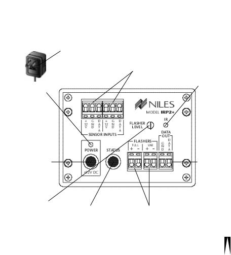
IRP2+ Parts Guide
|
Power Supply |
Remote Sensor Connections |
|
is a UL listed and |
enable you to connect up to |
|
approved 12vDC |
two remotely located IR sen- |
|
wall adapter. |
sors or keypads to the IRP2+. |
|
|
|
Red Power
Test LED enables you to test for proper power supply operation and shorts between + and GND on your sensor connections.
Green IR Test LED enables you to test for proper operation, interference, and for shorts between + and DATA on your sensor connections.
Power Socket provides fast and convenient connection of the power supply.
Flasher Level Control
enables you to reduce flasher level to match your A/V component’s sensitivity.
Status Socket
allows 12vDC wall adapter to provide amplifier on/off signal to “status” generator circuitry. See Power status page 22.
IR Data
Output allows the linking of multiple IRP units for systems requiring large numbers of flashers.
Flasher Connections
provide for a maximum of eight flashers (four IRC-1 flashers or eight IRC-2 flashers). When more than one flasher is connected to a single output, it is connected in series.
4
I N F R A R E D E X T E N D E R - M A I N S Y S T E M U N I T
IMPORTANT
Do not place the IRP2+ on top of or directly behind a television set. Some television sets produce intense electromagnetic interference which may disable your IR extender system.
Installation Considerations
conbecause Placement
2.
or a
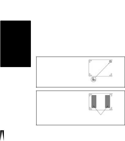
Figure 2: Table-Top Placement
1)Clean the bottom of the IRP2+ and the mounting surface with the enclosed alcohol pad.
2)Affix the enclosed self-adhesive rubber feet to the base of the IRP2+.
IRP2+
Base
Self-Adhesive
Rubber Feet
Figure 3: Wall-Mount Placement
1)Clean both mounting surfaces with the enclosed alcohol pad.
2)Affix the two enclosed strips of self adhesive Velcro® to the back of the IRP2+.
3)Mount the IRP2+ to the wall or cabinet back. Allow the adhesive to set as long as possible before connecting cables.
IRP2+
Base
Self-Adhesive
Velcro® strips
5

I N F R A R E D E X T E N D E R - M A I N S Y S T E M U N I T
Wiring
TECH TIP
From every IR Sensor location you must “home-run” a cable back to the IRP2+. Home run means that an individual cable is connected between each IR Sensor and the IRP2+. See Figure 4.
Room 1 |
Remotely Located |
Room 2 |
||||||||
IR Sensors |
||||||||||
|
|
|
|
|
|
|
|
|
|
Wire size is |
|
|
|
|
|
|
|
|
|
|
|
|
|
|
|
IRP2+ |
|
|
|
expressed by it's |
||
|
|
|
|
|
|
|
AWG (American |
|||
|
|
|
|
|
|
|
|
|
|
Wire Gauge) |
|
|
|
|
|
|
|
|
|
|
number. The lower |
|
|
|
|
|
|
|
|
|
|
|
|
|
|
|
|
|
|
|
|
|
the AWG number, |
|
|
|
|
|
|
|
|
|
|
the larger the wire, |
|
|
|
|
|
|
|
|
|
|
i.e., 20 AWG wire is |
|
|
|
|
|
|
|
|
|
|
|
|
|
|
|
|
|
|
|
|
|
|
|
|
|
|
|
|
|
|
|
|
physically larger than |
|
|
|
|
|
|
|
|
|
|
22 AWG. |
Figure 4: Home run the sensor cable from each sensor to the IRP2+.
IMPORTANT – AVOIDING INTERFERENCE
Avoid locating any of the cables, Sensors, Keypads or the Main System Unit near any potential sources of ElectroMagnetic Interference (EMI), such as light dimmers, speed controls for ceiling fans, electrical ballasts, television sets, large motors, heaters or air conditioners.
6
I N F R A R E D E X T E N D E R - M A I N S Y S T E M U N I T
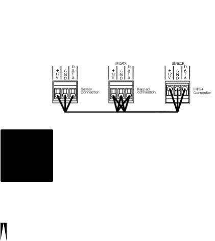
Keypad Wiring
Figure 5: An IR sensor cable is “daisy-chained” from a sensor to a keypad and then back to the IRP2+.
When you are placing both a keypad and a sensor (or two keypads) in one room you may “daisy-chain” using a single cable. A cable is run between the keypad and the sensor and a single cable is run from either the sensor or the keypad back to the IRP2+. See Figure 5.
CAUTION!
Do not use unshielded cable between any remote IR sensor or keypad and the IRP2+.
Sensor/Keypad Cable
shieldof two a bare runs D291, shieldruns
Flasher Cable
Niles infrared flashers come supplied with a 10 foot 2-conductor 22 gauge cable. Should you need to extend it, use a 16 gauge 2-conduc- tor cable (“zip-cord”). Shielding is not necessary for a flasher. Flasher wires can be extended up to 200 feet.
7
I N F R A R E D E X T E N D E R - M A I N S Y S T E M U N I T
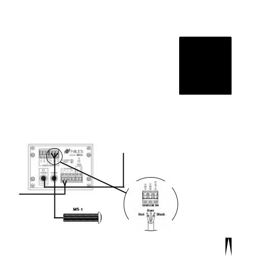
Installation
Before you begin, make sure that the sensor/keypad cables, the flasher cables and the 12vDC power supply cable will all reach the proposed location of the IRP2+. Mark the cables with labels describing where the cable originates (rather than which terminal on the IRP2+ it should connect).
For proper installation, follow the steps outlined below in the correct order. If you discover a fault in the course of installation, go on to the Troubleshooting Guide before continuing with the next installation step.
To unswitched AC outlet
Receiver
IRP2+
TOOLS
REQUIRED
• 1/8" Standard
Slotted
Screwdriver
• Wire Stripper
Figure 6:
IRP2+ Installation
IRP2+ Sensor
Connection
8
 Loading...