

Page 1

MODEL
IRP2+
IRP2+
IRP2+
INFRARED EXTENDER MAIN SYSTEM UNIT
INSTALLATION & OPERATION GUIDE
Page 2

II
NN FF RR AA RR EE DD
IIRRPP22++
Infrared Extender
Main System Unit
EE
XX TT EE NN DD EE RR
-- MM
AA II NN
SS
YY SS TT EE MM
UU
NN II TT
TABLE OF CONTENTS
Introduction 1
Features and
Benefits 3
IRP2+ Parts
Guide 4
Installation
Considerations 5
Installation 8
Testing the
IR Extender
System 11
TroubleShooting 12
Power Status 22
Specifications 26
Introduction
An infrared (IR) extender system enables you to control your IR
remote controlled A/V equipment from a remote location. This
enables you to place your A/V components out of sight (behind cabinet doors, in the rear of a room, or in a different room) and still conveniently control your equipment.
The model IRP2+ is an IR Main System Unit. It is one of three elements
that make up an infrared extender system:
1. IR Sensors receive IR commands from hand-held remote controls
and relay the commands to the Main System Unit via a 2-conductor
shielded cable. Generally, sensors are placed so that you can easily
and naturally point your remote control directly at them. Niles offers
an array of easily concealable sensors: wall-mount, ceiling-mount, surface-mount and table-top. IR sensors are the “eyes” of the system.
2. The IR Main System Unit provides a connection hub for the IR
sensors and the IR flashers and is generally located near the A/V components. The Main System Unit’s level controls and LED indicators
enable you to calibrate and troubleshoot an IR extender system. The
Main System Unit is the “heart” of an IR extender system.
3. Infrared Flashers transmit the infrared signals from the IR Main
System Unit to your A/V components. Niles manufactures both flooding flashers (model IRC-1) and miniature “pin-point” flashers (model
IRC-2). Flashers are the “voice” of an IR extender system.
Page 3
II
NN FF RR AA RR EE DD
EE
XX TT EE NN DD EE RR
-- MM
AA II NN
SS
YY SS TT EE MM
UU
NN II TT
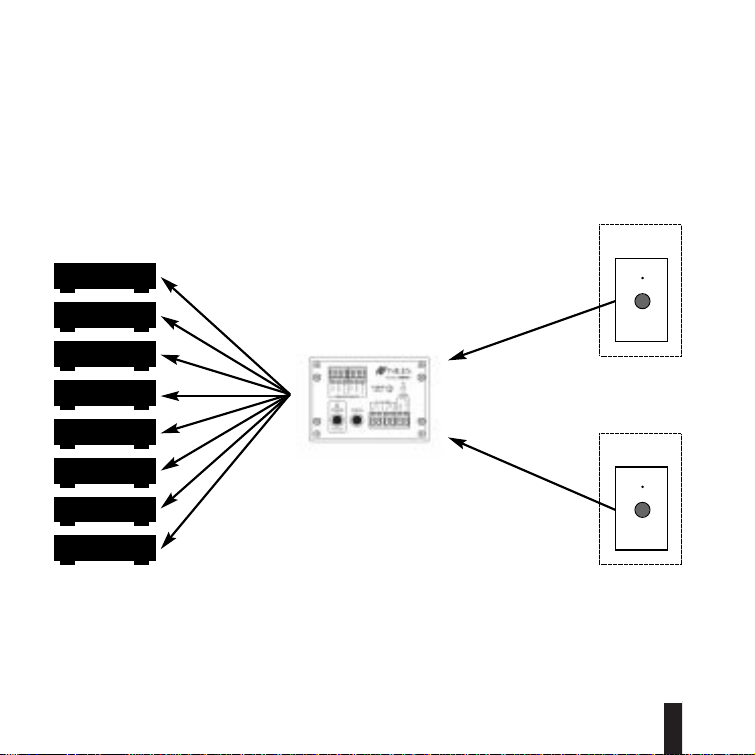
IR Controllable
A/V Components
Room 1
IR Main System Unit
Remotely
Located
IR Sensors
Room 2
Figure 1 In a typical system, the IRP2+ provides for the connection of up to two remote room sensors
(or keypads) and will control a maximum of eight audio/video components via its flasher connections
(four IRC-1 flashers or eight IRC-2 flashers).
2
Page 4

II
NN FF RR AA RR EE DD
EE
XX TT EE NN DD EE RR
-- MM
AA II NN
SS
YY SS TT EE MM
UU
NN II TT
Features and Benefits
The IRP2+ offers a number of improvements over other IR Extender
Main System Units:
● Universal system — compatible with virtually all brands of A/V
equipment and remote controls (the only exceptions are those
brands using carrier frequencies higher than 64kHz).
● ExclusiveNiles short-circuit protectionprovides foreasy installation.
● Accommodates two IR sensors or keypads.
● Provides two low-distortion, high-current Mosfet IR Flasher outputs;
one at full power, one with variable power.
● Red "Power" L.E.D. enables you to test for proper power supply
operation and shorts between + (positive) and GND (ground) on
your sensor connections.
● Green "IR" Test L.E.D. enables you to test for proper operation,
interference, and for shorts between + and DATA on your sensor
connections.
● Built in “Status” generator broadcasts the amplifier “on/off” power
status over existing IR wiring to provide power status display when
used with other Niles products like the IntelliPad that feature status
display LED’s.
● Screw connectors simplify installation.
● Printed circuit board design assures high reliability.
● Two year parts and labor warranty.
● Proudly made in the USA.
3
Page 5
II
NN FF RR AA RR EE DD
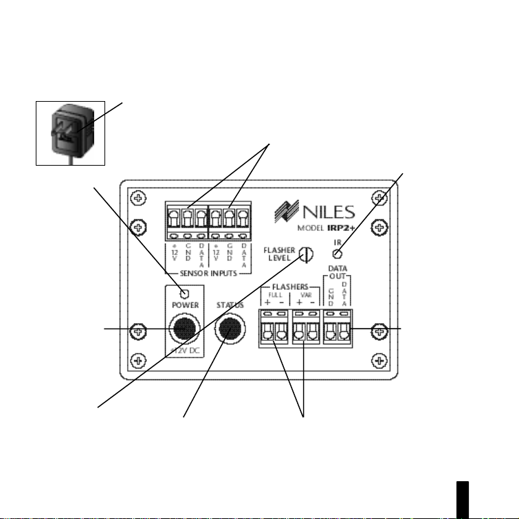
IRP2+ P arts Guide
Power Supply
is a UL listed and
approved 12vDC
wall adapter.
Red Power
Test LED
enables you to
test for proper
power supply
operation and
shorts between
+ and GND on
your sensor connections.
EE
XX TT EE NN DD EE RR
-- MM
AA II NN
Remote Sensor Connections
enable you to connect up to
two remotely located IR sensors or keypads to the IRP2+.
SS
YY SS TT EE MM
Green IR Test LED
enables you to test
for proper operation,
interference, and for
shorts between + and
DATA on your sensor
connections.
UU
NN II TT
Power Socket
provides fast and
convenient connection of the
power supply.
Flasher Level
Control
enables you to reduce flasher level to
match your A/V component’s sensitivity.
Status Socket
allows 12vDC wall adapter to
provide amplifier on/off signal
to “status” generator circuitry.
See Power status page 22.
IR Data
Output
allows the linking of multiple
IRP units for
systems requiring large numbers of flashers.
Flasher Connections
provide for a maximum of eight flashers
(four IRC-1 flashers or eight IRC-2 flashers).
When more than one flasher is connected
to a single output, it is connected in series.
4
Page 6
II
NN FF RR AA RR EE DD
EE
XX TT EE NN DD EE RR
-- MM
AA II NN
SS
YY SS TT EE MM
Installation Considerations
UU
NN II TT
IMPORTANT
Do not place the
IRP2+ on top of or
directly behind a
television set.
Some television
sets produce
intense electro-
magnetic interfer-
ence which may
disable your IR
extender system.
5
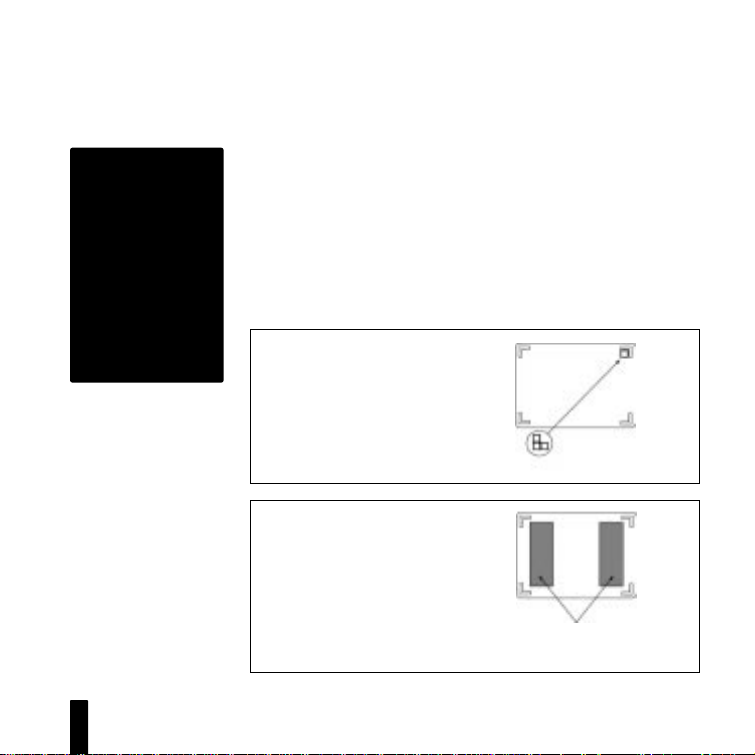
Placement of the IRP2+
Place the IRP2+ conveniently close to the equipment it will be controlling. Generally, the unit is placed in a concealed location because
its controls and indicators are only used during installation. Placement
possibilities include:
1) Table-top (on the floor or shelf behind the equipment) See Figure 2.
2) Wall-mount (affixed to the back of the equipment cabinet or a
nearby wall) See Figure 3 .
Figure 2: Table-Top Placement
1) Clean the bottom of the IRP2+
and the mounting surface with the
enclosed alcohol pad.
2) Affix the enclosed self-adhesive
rubber feet to the base of the
IRP2+.
Figure 3: Wall-Mount Placement
1) Clean both mounting surfaces with the
enclosed alcohol pad.
2) Affix the two enclosed strips of self
adhesive Velcro® to the back of the
IRP2+.
3) Mount the IRP2+ to the wall or cabinet
back. Allow the adhesive to set as long
as possible before connecting cables.
Self-Adhesive
Rubber Feet
Self-Adhesive
®
Velcro
IRP2+
Base
IRP2+
Base
strips
Page 7
II
NN FF RR AA RR EE DD
EE
XX TT EE NN DD EE RR
-- MM
AA II NN
SS
YY SS TT EE MM
UU
NN II TT
Wiring
From every IR Sensor location you must “home-run” a cable back to
the IRP2+. Home run means that an individual cable is connected
between each IR Sensor and the IRP2+. See Figure 4.
Room 1
Remotely Located
IR Sensors
Room 2
IRP2+
Figure 4: Home run the sensor cable from each sensor to the IRP2+.
IMPORTANT – AVOIDING INTERFERENCE
Avoid locating any of the cables, Sensors, Keypads or the
Main System Unit near any potential sources of ElectroMagnetic Interference (EMI), such as light dimmers, speed
controls for ceiling fans, electrical ballasts, television sets,
large motors, heaters or air conditioners.
TECH TIP
Wire size is
expressed by it's
AWG (American
Wire Gauge)
number . The lower
the AWG number,
the larger the wire,
i.e., 20 AWG wire is
physically larger than
22 AWG.
6
Page 8
II
NN FF RR AA RR EE DD
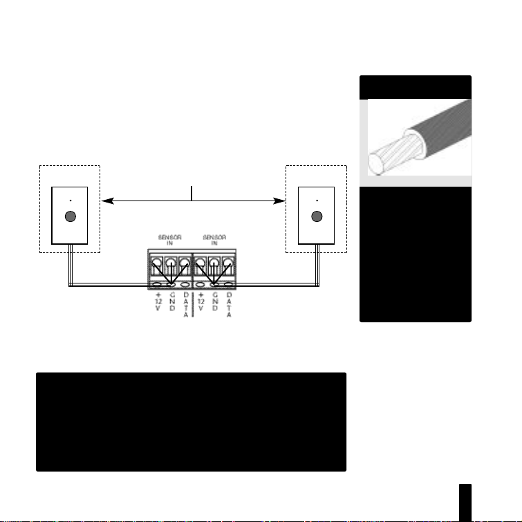
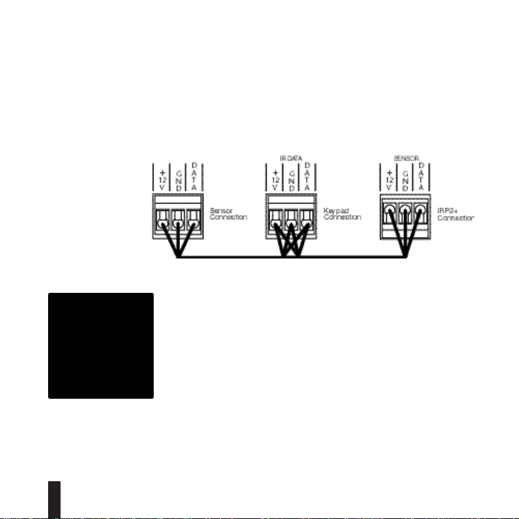
Figure 5: An IR
sensor cable is
“daisy-chained”
from a sensor to a
keypad and then
back to the IRP2+.
CAUTION!
Do not use unshielded cable
between any
remote IR sensor
or keypad and the
IRP2+.
EE
XX TT EE NN DD EE RR
-- MM
AA II NN
SS
YY SS TT EE MM
UU
NN II TT
Keypad Wiring
When you are placing both a keypad and a sensor (or two keypads)
in one room you may “daisy-chain” using a single cable. A cable is
run between the keypad and the sensor and a single cable is run from
either the sensor or the keypad back to the IRP2+. See Figure 5.
Sensor/Keypad Cable
The IRP2+ connects to IR sensors and keypads with 2-conductor shielded cable. Recommended cables are “data grade” cables made of two
22 gauge (or larger) conductors surrounded by a foil shield and a bare
drain (ground) wire. Data grade cable provides the capability for runs
of up to 500 feet to each sensor. Examples are West Penn D291,
Belden 8761 or Carol C2516. Any 22 to 16 gauge 2-conductor shielded cable available at a hardware store will accommodate 150 foot runs
to each sensor.
Flasher Cable
Niles infrared flashers come supplied with a 10 foot 2-conductor 22
gauge cable. Should you need to extend it, use a 16 gauge 2-conductor cable (“zip-cord”). Shielding is not necessary for a flasher. Flasher
wires can be extended up to 200 feet.
7
Page 9
II
NN FF RR AA RR EE DD
EE
XX TT EE NN DD EE RR
-- MM
AA II NN
SS
YY SS TT EE MM
UU
NN II TT
Installation
Before you begin, make sure that the sensor/keypad cables, the flasher cables and the 12vDC power supply cable will all reach the proposed location of the IRP2+. Mark the cables with labels describing
where the cable originates (rather than which terminal on the IRP2+
it should connect).
For proper installation, follow the steps outlined below in the correct
order. If you discover a fault in the course of installation, go on to the
Troubleshooting Guide before continuing with the next installation step.
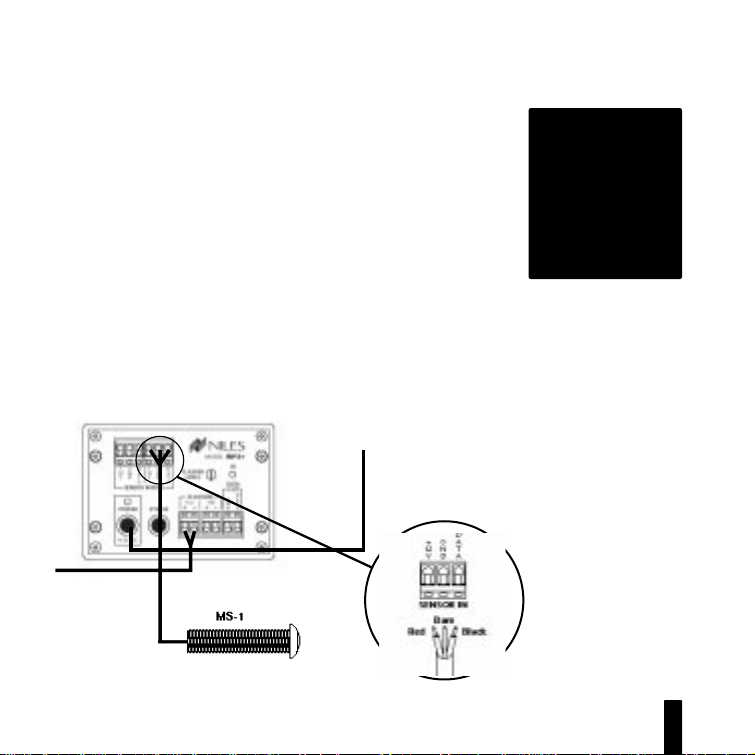
To
unswitched
AC outlet
Receiver
IRP2+
MS-1 Sensor
TOOLS
REQUIRED
• 1/8" Standard
Slotted
Screwdriver
• Wire Stripper
Figure 6:
IRP2+ Installation
IRP2+ Sensor
Connection
8
Page 10

II
NN FF RR AA RR EE DD
EE
XX TT EE NN DD EE RR
-- MM
AA II NN
SS
YY SS TT EE MM
UU
NN II TT
STEP
1. Connect and test the
power supply. If it tests OK,
unplug the connector from
the power socket and proceed.
2. Connect the first Sensor/
Keypad cable to either one of
the Sensor inputs.
3. Test for shorts and interference.
DESCRIPTION
A) Plug the supplied 12vDC power supply into an unswitched
120V AC outlet .
B) Plug the connector into the socket marked “Power” on the
IRP2+.
C) If the Power LED does not light, test the unswitched 120
VAC outlet with another appliance. If the outlet tests OK, you
have a defective power supply which must be replaced for you
to continue.
A) Strip 1/4” of insulation from the wire ends of the cable.
B) Attach the exposed wire ends to the appropriate connector.
Be careful to prevent a filament of wire from shorting out two
connectors. Red = +12v Bare = GND Black = DATA
A) Reconnect the power supply. If the Power LED lights and
the IR Test LED stays off, unplug the connector from the
power socket and proceed to Step 4. The following LED conditions show a fault:
• If Power LED is Off there is a short between +12v and GND
• If IR Test LED is On or Flickers there is a short between DATA
and GND Or Interference is present.
Before you proceed to Step 4 consult the Troubleshooting
Section beginning on page 12
9
Page 11

II
NN FF RR AA RR EE DD
EE
XX TT EE NN DD EE RR
-- MM
AA II NN
SS
YY SS TT EE MM
UU
NN II TT
STEP
4. Connect the flashers to the
flasher outputs. If you need to
extend the wire, use a 2-conductor 16 gauge or larger (See
DESCRIPTION
Route the connecting 2-conductor wire to the IR Main
System Unit. Connect the ends of the wire to the corresponding positive and negative terminals labeled “Flasher”
on the IRP2+.
Tech T ip on page 6).
BE SURE TO OBSERVE PROPER POLARITY WHEN
CONNECTING OR EXTENDING THE FLASHER WIRE.
IRC-1 the wire lead marked with a gray stripe is
negative (-); the unmarked lead is positive (+).
IRC-2 the silver colored wire lead is negative (-); the
copper colored wire lead is positive (+).
5. Connect multiple flashers to
a single output by connecting
in series.
Use crimp caps, wire nuts or solder to connect the negative
of one flasher to the positive of the next flasher as shown to
create a series circuit.
IRC-1 Flooding Flasher allows a maximum of TWO in series
–+
IRC-2 MicroFlasher allows a maximum of FOUR in series
+–
6. Test for proper operation
with all sensors and remote
controls.
10
Page 12

II
NN FF RR AA RR EE DD
EE
XX TT EE NN DD EE RR
-- MM
AA II NN
SS
YY SS TT EE MM
UU
NN II TT
T esting the IR Extender System
Test your IR Extender system by following the three principal guidelines:
1. All components can be operated. Test all of your remote controls
for all of your equipment.
2. Operation is consistent. A good test is to repeatedly step from
Pause to Play with your VCR, CD, Laser, or Tape player remote control. Operation should be identical to standing in front of the component with the remote control pointed directly at the sensor window.
3. Maximum Range between the Remote Control and the Niles IR
Sensor is similar to the maximum range between the Remote Control
and the A/V component’s IR sensor. Typically a remote control with
two batteries will have a 15 to 20 foot range and a remote with four
batteries will have a 20 to 30 foot range.
11
Page 13

II
NN FF RR AA RR EE DD
EE
XX TT EE NN DD EE RR
-- MM
AA II NN
SS
YY SS TT EE MM
T roubleshooting Guidelines
There are four basic problems which prevent proper operation. In the
order of probability the problems are:
Bad Connections or Wiring
If the connections or wiring are wrong, loose, shorted or open the system
will not operate properly. The symptoms could include: Power LED flickers
or is off, IR Test LED is continuously flickering or on without any remote
control use, intermittent operation or no operation.
3
4
and
Steps
•
13
Steps
•
15
Steps
•
26
Steps
•
Flasher Level is Too High
Many audio/video co mp on e nt ’s sen so rs ar e o ve rl oaded by receiving
to o st r o ng of an IR com ma n d f r o m t h e flasher. Symptoms can include:
popping and clicking sounds from the speakers when a button is pressed on
the remote control, poor IR receiving range, intermittent operation or no
operation.
15
Step
•
Optical or Electromagnetic Interference
Sunlight, reflections, neon signs and other sources of infrared light or television sets, light dimming controls and other sources of electromagnetic fields
can induce noise and interference into your IR extender system. Symptoms
can include: flashback LED’s continuously flickering or on without any
remote control use, poor range, intermittent operation or no operation.
32
Steps
•
test your power supply connections.
•
14
23
thru
,
•
•
18
thru
•
27
and
tests your cable for shorts and opens.
•
provides detailed instructions on setting the proper flasher level.
through
25
thru
test your Sensor connections.
•
test your Flasher connections.
38
troubleshoot interference problems.
•
UU
NN II TT
12
Page 14

II
NN FF RR AA RR EE DD
EE
XX TT EE NN DD EE RR
Optical Feedback Loop
If you have an IR sensor in the same room as a flasher, and you have
some low-level noise or interference, an optical feedback loop can
occur which will interfere with proper operation. Symptoms can
include: poor range, intermittent operation or no operation.
19
Steps
•
feedback loops.
Start from Step One
In your installation you may be faced with a combination of the four
problems or symptoms that are universal to all of the problems.
Rather than trying to guess which problem you have, use a process of
elimination. The Troubleshooting section is designed to eliminate the
most common problems first. If you start from Step 1 and methodically check everything you will find the problem in much less time than
the troubleshooter who makes assumptions.
through
-- MM
AA II NN
22
provide instructions for eliminating optical
•
SS
YY SS TT EE MM
UU
NN II TT
13
Page 15

II
NN FF RR AA RR EE DD
EE
XX TT EE NN DD EE RR
T roubleshooting Guide
-- MM
AA II NN
SS
YY SS TT EE MM
UU
NN II TT
1
•
Test Remote Control
Verify that the remote control works by operating the equipment directly. If the remote does
not operate your system directly, replace the
batteries of the remote control. Replace the
remote control if necessary
2
•
Flasher Positioning
Flashers operate line-of-sight; be sure they are
unobstructed and aimed at the front panel
sensor windows of your components.
3
•
12v DC Power Supply
Test that the red IRP2+ power LED is on when
the wall adapter is plugged into an
unswitched AC outlet.
• Power LED On: Go to Step 13
• Power LED Off: Go to Step 4
4
•
Disconnect Sensors
If the power LED does not light, disconnect all
sensors and retest the power supply.
• Power LED On: Go to Step 6
• Power LED Off: Go to Step 5
.
5
•
Replace Power Supply
Either your power supply or your IRP2+ is defective. If you have another 12v DC power supply,
first check that it has the same polarity (+ on
the tip, GND on the sleeve). Plug the new
power supply in and observe the Power LED.
• Power LED On: Retest System per page 11
• Power LED Off: Return IRP2+ to your local
Niles dealer for testing
6
•
Test Sensor Input 1
Reconnect one of the sensor cables. Re-test;
plug the power supply back in and observe
the Power LED.
• Power LED On: Go to Step 7
• Power LED Off: Go to Step 8
7
•
Test Sensor Input 2
A) If you DO NOT have a second sensor/keypad,
Go to Step 12.
B) If you DO have another sensor/keypad, connect it to the second sensor input and re-test.
• Power LED On: Go to Step 12
• Power LED Off: Go to Step 8
14
Page 16

II
NN FF RR AA RR EE DD
EE
XX TT EE NN DD EE RR
-- MM
AA II NN
SS
YY SS TT EE MM
UU
NN II TT
8
•
Short between +12v (positive) and GND
(ground).
Examine the connectors for a hair-like filament
of wire between any of the contacts at the
IRP2+ and at the sensor or keypad.Then retest.
• Power LED On: Go to Step 12
• Power LED Off: Go to Step 9
9
•
Test the Cable for Shorts
Disconnect the cable at both ends (at the sensor and at the IRP2+) and test it for shorts. Use
an ohm meter or electrical continuity checker.
You should read an open (Infinite Ohms)
between Red and Bare, Red and Black or Bare
and Black.
• Short in Cable: Replace cable
• Cable tests OK: Go to Step 10
10
•
Replace the IRP2+
If you have another IRP2+, replace the one in
the system and retest, if not go to Step 11.
11
•
Replace the Sensor or Keypad
If you have another Sensor or Keypad,
exchange it and retest the system, otherwise
return the IRP2+ and the sensor/keypad(s) to
your local Niles dealer for testing.
15
12
•
System suddenly seems to beOK again.
The connections were poor and by touching
and inspecting them you have changed their
condition. Jiggle and tug on the wires and
recheck the connections. If they all seem secure,
retest the entire system per the guidelines on
page 1 1.
13
•
IR LED without any IR input.
Observe the green IR Test LED on the IRP2+
with the power supply plugged in and all sensors and flashers connected.
• IR Test LED is Onor is Flickering: Go to
Step 32
• IR Test LED is Off: Go to Step 14
14
•
IR LED with IR input.
Have someone watch the green IR LED on the
IRP2+ while you aim a remote control at a
remote sensor and press a button.
• IR Test LED Flashes: Go to Step 15
• IR Test LED Off: Go to Step 23
15
•
Flasher Connections
Verify the polarity of the flasher connections.
Flashers must be connected according to
Steps 4 and 5 on page 10. Examine the con-
Page 17

II
NN FF RR AA RR EE DDEEXX TT EE NN DD EE RR
-- MM
AA II NN
SS
YY SS TT EE MM
UU
NN II TT
nectors for a hair-like filament of wire between
any of the contacts. Retest the system according to the guidelines on page 11.
• Good Operation: Congratulations!
• Poor Operation: Go to Step 16
16
•
Flasher Output Too High
Som e audio/video c o m ponent’s sensors are
overloaded by too strong a command
fr om the flasher. Connect the flasher(s) to the
variable output of the IRP2+ and use a 1/8”
slotted screwdriver to reduce the output level
to minimum (counter-clockwise). Retest the
system according to the guidelines on page 11.
• Poor Operation: Move the flasher so that it
is farther away from the sensor window
or off to the side of the sensor window.
Retest the system.
• Poor Operation: Start raising the level (a
quarter turn clockwise each time) and retesting until level is back to full.
• Poor Operation Continues: Go to Step 17
17
•
Test Flashers.
A) If you have only ONE FLASHER, reconnect it
to the other flasher output. Retest the system
according to the guidelines on page 11.
• Good Operation: Congratulations!
• Poor Operation: Go to Step 19
B) If you have MORE THAN ONE FLASHER, disconnect all of them and reconnect one flasher
at a time. Test for improved operation.
Continue testing until you have identified the
defective flasher. Test all of your flashers.
•All flashers appear defective:Go toStep18
• One flasher doesn’t work: Return the defec-
tive flasher to your dealer
• All flashers now work: Congratulations!
18
•
Test Flasher Outputs
Reconnect one flasher to the second flasher output of the IRP2+. Test for improved operation.
Repeat Step 16 (adjust flasher level and position). Test for improved operation.
• Good Operation: Congratulations!
• Poor Operation: Repeat this step with anoth-
er flasher. Retest.
• Poor Operation Continues: Go to Step 19
19
•
Sensors in the Same Room as a Flasher?
• If you have sensors in the same room as a
flasher: Go to Step 20
• If all sensors are in remote locations with-
out flashers : Go to Step 21
• If you have keypads only: Go to Step 21
16
Page 18

II
NN FF RR AA RR EE DD
EE
XX TT EE NN DD EE RR
-- MM
AA II NN
SS
YY SS TT EE MM
UU
NN II TT
20
•
Optical Feedback Loop
If there is an IR sensor and an IR flasher located
within the same room an "optical IR feedback
loop" can occur. Replace the IRC-1 Flooding
Flasher with an IRC-2 MicroFlasher on the front
panel sensor window of each component.
Place the enclosed IR blocking cover over each
of the IRC-2 flashers. Retest the system.
• Good Operation: Congratulations!
• Poor Operation: Go to Step 16 (adjust Flasher
Level and Position) Retest system.
• Still Poor Operation: Go to Step 21
21
•
Replace IRP2+ and Flasher(s)
Reconnect the system with a new IRP2+ and
new flasher(s).
• Poor Operation Continues: Go to Step 22
22
•
Interference that Does Not Light the IR
Test LED
Some very rare examples of interference (both
optical and electro-magnetic) do not light up
the IR test LED but do prevent proper operation. Go to steps 36 and 37. Examine your
installation carefully for a source of low-level
optical or electromagnetic interference.
23
•
Disconnect All Sensors and Keypads and
Test One Sensor Input
Disconnect all Sensors and Keypads.
Reconnect one of the sensor cables and retest
the system (Have someone watch the green IR
LED on the IRP2+ while you aim a remote control at a remote sensor and press a button).
• IR Test LED Flashes: Go to Step 24
• IR Test LED Off: Go to Step 25
24
•
Test Second Sensor Input
A) If you DO NOT have a second sensor/
Keypad, Go to Step 25.
B) If you DO have another sensor/keypad,
connect it to the second sensor input. Retest
the system (Have someone watch the green IR
LED on the IRP2+ while you aim a remote control at a remote sensor and press a button).
• IR Test LEDFlashes: Go to Step 12
• IR Test LED Off: Go to Step 25
25
•
Bad Connections at the IRP2+ and/or at
the Sensor/Keypad.
Verify that all connections are good both at
the IRP2+ Sensor Inputs and at the remote
sensor/keypad. Check that the jacket of each
conductor has been properly stripped and
17
Page 19

II
NN FF RR AA RR EE DDEEXX TT EE NN DD EE RR
-- MM
AA II NN
SS
YY SS TT EE MM
UU
NN II TT
inserted into the connector. Examine the connectors for a hair-like filament of wire between
any of the contacts. Repair as necessary. Retest
the system (have someone watch the green IR
LED on the IRP2+ while you aim a remote control at a remote sensor and press a button).
• IR Test LED Flashes: Congratulations!
• IR Test LED Off: Go to Step 26
26
•
Test Cable for Shorts
Disconnect the cable at both ends (at the sensor
and at the IRP2+) and test it for shorts. Use an
ohm meter or electrical continuity checker. You
should read an open (Infinite Ohms) between
Red and Bare, Red and Black or Bare and Black.
If you find a short, replace or repair the cable as
necessary. Retest the system (Have someone
watch the green IR LED on the IRP2+ while you
aim a remote control at a remote sensor and
press a button).
• IR Test LED Flashes: Congratulations!
• IR Test LED Off: Go to Step 27
27
•
Test Cable for Opens
At one end of the cable, twist the exposed
copper ends of the Red (+) and the bare
(GND) conductors together. At the other end
of the cable, use an Ohm meter or continuity
checker to check for a break in the cable. You
should read a short (zero ohms) between the
exposed copper ends of the Red (+) and the
bare (GND) conductors. Repeat this test with
the Red (+) and the Black (DATA) conductors.
If you find an open, replace or repair the cable
as necessary. Retest the system (have someone
watch the green IR LED on the IRP2+ while
you aim a remote control at a remote sensor
and press a button).
• IR Test LED Flashes: Congratulations!
• IR Test LED Off: Go to Step 28
28
•
Connect Sensor to Other Input of the IRP2+
Disconnect the sensor and reconnect it to the
other sensor port on the IRP2+. Retest the system (Have someone watch the green IR LED
on the IRP2+ while you aim a remote control
at a remote sensor and press a button).
• IR Test LED Flashes: Congratulations!
• IR Test LED Off: Go to Step 29
29
•
Replace the IRP2+ and/or the Sensor/Keypad
If you have another IRP2+, sensor or keypad,
change it and retest the system, otherwise
return the IRP2+ and the sensor/keypads to
your local Niles dealer for testing.
18
Page 20

II
NN FF RR AA RR EE DD
EE
XX TT EE NN DD EE RR
-- MM
AA II NN
SS
YY SS TT EE MM
UU
NN II TT
30
•
Disconnect All Sensors and Keypads
Observe the IR Test LED.
• IR Test LED is ONor Flickering: Go to Step 33
• IR Test LED is OFF: Go to Step 35
31
•
Move the IRP2+ to avoid Electromagnetic
Interference
It is possible that the IRP2+ is receiving electromagnetic interference from a nearby television
or other appliance. Move the IRP2+ to another
location and reconnect the power supply.
Observe the IR Test LED.
• IR Test LED is ONor Flickering: Go to Step 34
• IR Test LED is OFF: Y ou have EMI in your origi-
nal location. Relocate the IRP2+ according to
the guidelines on Page 5.
32
•
Replace the IRP2+
If you have another IRP2+, exchange it and
retest the system, otherwise, return the IRP2+
to your local Niles dealer for testing.
33
•
Test First Sensor Input
Connect one sensor/keypad to the first Sensor
Input. Observe the IR Test LED.
• IR Test LED Off: Go to Step 36
• IR Test LEDis On or Flickering: Go to Step 37
34
•
Test Second Sensor Input
A) If you DO NOT have a second sensor/keypad, Go to Step 12.
B) If you DO have another sensor/keypad, connect it to the second sensor input. Observe the
IR Test LED.
• IR Test LEDis On or Flickering: Go to Step 37
• IR Test LED Off: Go to Step 12
35
•
Test for Shorts
A) Verify that all connections at the IRP2+ are
correct. Look for a hair-like filament of wire
between the two contacts.
B) Verify that the sensor/keypad connections
are correct. Look for a hair-like filament of wire
between the two contacts.
C) Disconnect the sensor/keypad cable at both
ends and test the cable itself for shorts. Use an
ohm meter or electrical continuity checker. You
should read an open (Infinite Ohms) between
Red and Bare, Red and Black or Bare and Black.
After testing all connections and cable, observe
the IR test LED.
• IR Test LED is Onor Flickering: Go to Step 38
• IR Test LED is Off: Congratulations
19
Page 21

II
NN FF RR AA RR EE DD
EE
XX TT EE NN DD EE RR
-- MM
AA II NN
SS
YY SS TT EE MM
UU
NN II TT
36
•
Test for Optical Interference
Reconnect the problematic sensor/keypad to
the IRP2+. Cover up the Sensor with a piece of
cardboard (your hand will actually create electromagnetic interference under some conditions). Observe the IR test LED.
• IR Test LED On or Flickering: Go to 3 7
• IR Test LED Off: Go to 3 6
37
•
Optical Interference
Identify the source of the interference. The
most common sources of optical interference
are listed in the order of their probability:
A) Sunlight. Reflections from windows, mirrors,
swimming pools, shiny floors or objects.
B) Fluorescent light fixtures.
C) Neon signs.
D) A malfunctioning IR Remote Control.
E) A malfunctioning Infrared Motion Detector
on your Security system.
Either re-orient the sensor or move the source
of interference. Niles infrared sensors have
built-in filters to attenuate the effect of visible
light. If you add additional filtration you will
reduce the effectiveness of the system with
remote controls as well as the interference.
If you are using the MS-1 or the MS-2 miniature sensors consider exchanging them for
IRR-4D, TIR-1 or the CMS-3 ceiling sensor.
These three sensors have AGC circuits which
serve as automatic filters.
If you choose to attempt to filter an MS-1 or
MS-2, try a temporary material (e.g. a single
thickness of facial tissue) and test whether filtration will solve the interference and still give
acceptable range.
38
•
Electromagnetic Interference (EMI)
Identify the source of the interference. The
most common sources of electromagnetic
interference are listed in the order of their
probability:
A) Televisions (particularly large direct view
sets).
B) Wall-mounted light dimmers or variable
speed controls for ceiling fans. These controls
emit more interference when turned down
halfway. They emit little or no interference
when turned up all the way (brightest position).
C) Fluorescent lights (the electronic ballast
sometimes emits EMI)
D) Large appliances (air-conditioners, pumps,
motors, compressors etc.)
E) AC line noise (noise brought into the system
20
Page 22

II
NN FF RR AA RR EE DD
EE
XX TT EE NN DD EE RR
via the wall outlet connected to the IRP2+)
Identify the EMI source by turning potential
sources on and off (or fully up and fully down)
and watching for any change in the IR Test LED
on your IRP2+. Once you have identified the
source of interference:
1) Move the sensor or the sensor cable away
from the EMI source or move the source of the
EMI away from the sensor or the cable.
2) Shield the sensor with a metal J-Box.
3) Connect the Sensor’s GND terminal to true
earth ground (if this isn’t feasible use the IRP2+
GND terminal).
4) Place a ferrite ring around the cable creating
the interference. Ferrite rings can be purchased
from an electronic supply store.
-- MM
AA II NN
SS
YY SS TT EE MM
UU
NN II TT
21
Page 23

II
NN FF RR AA RR EE DD
EE
XX TT EE NN DD EE RR
-- MM
AA II NN
SS
YY SS TT EE MM
UU
NN II TT
IMPORTANT
For the
IntelliPad’s status
feedback feature
to work, the pre-
amp/receiver con-
trolling your sys-
tem should have a
switched AC out-
let, a switched
outlet is a 120v
AC outlet that
switches off,
when the preamp/
rec-eiver is off
and switches on
when it is on via
remote control.
Power Status — Introduction
By adding an IntelliPad™ to your IRP2+ Infrared Extender System you
will add a remarkable level of convenience to your system. The IntelliPad
is the world’s first programmable, wall-mounted keypad system that
provides a unique L.E.D. power status display and the convenience of
true one-touch remote control of complex audio/video systems.
The IntelliPad’s status feedback feature eliminates the guesswork common with standard IR control systems. The power L.E.D. on the
IntelliPad indicates the On/Off condition of the system’s
preamp/receiver.
Built-in intelligence tracks the On/Off condition of the preamp/receiver so the IntelliPad knows when it’s appropriate to issue the power
command, even when the user doesn’t. The system maintains perfect
synchronization between the amplifier and the user.
By combining an optional Niles 12vDC power supply with your IRP2+
you can send a status signal to an IntelliPad without running any additional wiring. Built into the IRP2+ is a Niles Status Signal Generator.
When the IRP2+ sees 12vDC at the status jack it broadcasts a Status
signal over your existing IR sensor wires. Any IntelliPad connected to
one of your sensor wires will display power status.
22
Page 24

II
NN FF RR AA RR EE DD
EE
XX TT EE NN DD EE RR
-- MM
AA II NN
SS
YY SS TT EE MM
UU
NN II TT
The IntelliPad
®
Source Select Keys
A single press of one of these
keys will:
1. T urn on the Preamp/Receiver
if it was off.
2. Change the input of your preamp/receiver to the selected
source.
3. Changes the function of the
Source Control Keys so that
they operate the selected
source.
4. Display which source is
selected by backlighting the
corresponding Sour
ce Label.
5. T urn on the local speakers
(un-mute the speaker relay)
Status LED
When the preamp/receiver is
on, the status LED is lit. The
color of the LED displays
whether the local speakers are
on or muted.
GREEN - Local Speakers and
the Preamp/Receiver are on
RED - Local speakers are off,
but the system is on.
OFF - System is off.
23
Source Control Keys
A touch to any of the source
control keys will operate the
selected source only.
Mute Key
A touch to this key controls the IntelliPad’s
built in speaker mute feature. You can mute
the local speakers anytime, by pressing the
Mute Key. To turn the local speakers back
on (or unmute) you may press either the
Mute key or one of the six Source Select
keys.
olume Key
V
This key raises
and lowers the
volume of your
main system
amplifier.
Page 25

II
NN FF RR AA RR EE DD
EE
XX TT EE NN DD EE RR
-- MM
AA II NN
SS
YY SS TT EE MM
UU
NN II TT
CONVERTING
A LOW
VOL TAGE
CONTROL
OUTPUT TO
V
DC
12
Many compo-
nents, particularly
surround proces-
sors and digital
preamplifiers,
provide a low
voltage whenever
the component is
“on” rather than
in “standby”. For
the IRP2+ to cor-
rectly broadcast
power status you
must install an
optional Niles
OTI-512 Opto-
Isolated trigger
interface. The
OTI-512 will con-
vert 3-30 volts AC
or DC to 12vDC.
Power Status — Installation Considerations
Proper Power Supply
You must connect a Niles 12vDC wall adapter (Niles FG00665) into
the switched AC power outlet of the preamp/receiver in your system.
Any 12vDC power supply with a minimum of 100mA current capacity can be substituted.
Extending the Cable
If you must extend the cable from the wall adapter to the IRP2+’s status input jack be sure to maintain correct polarity. The tip of the plug
should be positive (+) and the sleeve negative (-). Any 16 gauge 2conductor cable can be used to extend the power status cable up to
200 feet.
Checking the Power Supply
It is possible to check the status power supply itself and any connections that were made to extend the cable by inserting the status plug
into the Power jack on the IRP2+. If the Power LED lights the status
power supply and connections are OK. If the Power LED does not
light check all connections and replace the power supply if necessary.
For more details on incorporating the IntelliPad please refer to the
IntelliPad’s users manual.
24
Page 26

II
NN FF RR AA RR EE DD
EE
XX TT EE NN DD EE RR
-- MM
AA II NN
SS
YY SS TT EE MM
UU
NN II TT
Stereo Receiver
IR Flasher
DC Power
Supply
Rear Panel of
Intellipad™
plugged
into
Switched
Outlet
Figure 7:
IntelliPad Basic Configuration
utilizing Status Feedback and
Speaker Relay Features.
Loudspeaker Loudspeaker
IRP2+
DC Power
Supply
25
Page 27

II
NN FF RR AA RR EE DD
EE
XX TT EE NN DD EE RR
-- MM
AA II NN
SS
Specificat ions
IR System
Compatible with virtually all brands of remotes using carrier frequencies between 18 and 100kHz. As of this publication date, the only
known components using carrier frequencies outside this range are
Bang & Olufsen components and 1996 model year Pioneer receivers
using the ISC remote control (e.g. VSX-D704S).
iring Requirements
W
Individual home-runs of 2 conductor shielded cable from each
sensor/keypad, West Penn D291 or equivalent
Unit Dimensions
4” wide x 1 3/4” high x 2 7/8” deep
YY SS TT EE MM
UU
NN II TT
Power Requir
ements
12vDC500 mA power supply (included).
26
Page 28

Niles Audio
Corporation
www.nilesaudio.com
12331 S.W. 130 Street
Miami, Florida, 33186
Tel: (305) 238-4373
Fax: (305) 238-0185
© 1999 Niles Audio Corporation. All rights reserved. Because Niles constantly strives to improve the
quality of its products, Niles reserves the right to change product specifications without notice. Niles,
the Niles logo and IntelliPad are registered trademarks of Niles Audio Corporation. Velcro is a
registered trademark of Velcro (USA), Inc. Decora Home Controls is a registered trademark of Leviton
Manufacturing Company. Printed in USA 1/99 DS00156A
 Loading...