

Page 1
™
Intelligent Power Management Systems.
INSTALLATION & OPERATION GUIDE
B LENDING H IGH F IDELITY AND A RCHITECTURE
®
AC-6+
AC-6+
6 OUTLET POWER MANAGEMENT SYSTEM
Page 2

IMPORTANT SAFETY PRECAUTIONS
Your iPOWER™product represents the latest in power management and protection technology.
However, like any electronic device, an inappropriately or improperly installed device may not perform as intended. By following a few common sense precautions, your iPOWER
™
product will give
you a lifetime of worry-free performance.
The following safety precautions apply to all iPOWER™products.
READ AND OBSERVE THE FOLLOWING SAFETY PRECAUTIONS AT ALL TIMES.
WARNING! Power Source:
Use only with a 3-prong standard AC outlet or a GROUNDED 2 to
3 prong adapter. iPOWER
™
products cannot provide power protection without a grounded AC
source. Never use a 3 to 1 adapter plug — this will disable all protection from your iPOWER
™
unit and will void the Limited Lifetime Warranty and Connected Equipment Guarantee.
All rooftop devices connected to your iPOWER
™
products should be grounded according to
the National Electrical Code (NEC). Do not place any rooftop device where it can come into
contact with power lines or any power circuit.
WARNING! Operating Voltage: Any equipment plugged into an iPOWER™product must have
a 120V, 60Hz rating.
WARNING! Power Rating: Check the power consumption (watts) of each device that will be
powered by an iPOWER
™
product. Be sure that the total of all devices being connected does
not exceed 1800 watts.
WARNING! Water and Moisture: Do not use any iPOWER™product in an area where it may get
wet, such as near a bathtub, sink, laundry facility, in a wet basement, or near a swimming pool.
WARNING! Ventilation: While iPOWER™products do not generate a significant amount of heat,
they should not be placed directly on a bed, rug, or sofa that may obstruct the unit’s natural heat
dissipation abilities.
Page 3

IMPORTANT SAFETY PRECAUTIONS
CAUTION! Heat: iPOWER™products should not be placed on or in close proximity to heat sources
such as radiators, heat registers, stoves, or on top of other devices (including amplifiers and receivers)
that produce heat.
WARNING! Power Cord Protection: Power cords and remote trigger cables should be routed
so that they are not likely to be walked on, chewed by pets, or pinched by objects placed on
them. Pay special attention to the place where the cord meets the plug and where the cord
enters the device.
WARNING! Object And Liquid Entry: Care should be taken that no objects or liquids fall
onto or into the device. Do not use alcohol on the device.
WARNING! Damage Requiring Service: Customers should not attempt to repair iPOWER
™
products. These devices should be serviced by an authorized service technician when:
• The power supply cord or the plug has been damaged
• Objects have fallen, or liquid has been spilled, into the device
• The device has been exposed to rain
• The device shows a marked change in performance or does not appear to function normally
• The device has been dropped, or the enclosure has been damaged
Page 4

1
CONGRATULATIONS!
Thank you for purchasing a Niles iPOWER™Intelligent Power Management
System. Niles iPOWER
™
products are the result of years of research and development and are the most advanced and complete power management devices
available. With iPOWER
™
in your system, you have complete confidence knowing that your audio/video components have a clean power supply free of noise
and distortion. The result—your home entertainment system will perform as is
designers intended, while being fully protected from electrical noise and potentially damaging spikes and surges.
In addition to power protection and performance enhancement, the iPOWER
™
AC-6+ offers triggering options which allow for control of your system’s start-up
and shut-down procedures. With a little planning, your AC-6+ can put control of
your home entertainment system at your fingertips.
Niles manufactures the industry's most complete line of custom installation components and accessories for audio/video systems. For a free full-line catalog write:
Niles, Catalog Request, P.O. Box 160818, Miami, Florida 33116-0818 or visit our
web site at www.nilesaudio.com
.
Page 5

2
TABLE OF CONTENTS
INTRODUCTION 3
KEY TECHNOLOGIES 4
UNIT DETAILS 7
INSTALLATION OVERVIEW 8
PACKAGE CONTENTS 9
PLANNING YOUR SYSTEM 10
PLANNING YOUR AC CONNECTIONS 12
MAKING CONNECTIONS 13
USING THE REMOTE TRIGGER FEATURE 14
TROUBLESHOOTING 17
SPECIFICATIONS 19
TABLE OF CONTENTS
Page 6
3
INTRODUCTION
Never in the history of power protection has there been a product line that has
revolutionized the industry the way that Niles' iPOWER
™
has. iPOWER™Intelligent Power
Management Systems represent a breakthrough in three main areas:
power protection, noise
filtration,
and power management. Based on solid scientific principles, clever engineering, and
fastidious execution, iPOWER
™
devices are built to the most stringent standards in the industry and
provide the maximum electrical protection and advanced performance enhancing technology.
iPOWER's i3™(instantaneous, impenetrable, and virtually indestructible) three-stage power protection circuitry stands head and shoulders above the industry in terms of delivering instantaneous
response time. Its clamping levels are among the lowest in the industry, providing unrivaled
electrical protection for its connected equipment. Its iQ
™
Optimal Q Impulse Noise Filtering
technology has the ability to reduce detail-obscuring “noise” on the AC power line, resulting in
performance that’s sure to please even the most demanding eyes and ears. In fact, iPOWER
™
may
be the first "audiophile-approved" power protection technology available at any price. Additionally,
its iDefinition
™
HDTV-ready coax circuitry provides protection while minimizing signal loss from
input to output so images are razor sharp and colors are vivid. Plus, with a full complement of true
line diagnostics, an intuitive, flexible triggering protocol, and user-friendly one button operation,
your AC-6+ puts you in complete control of your system.
Model AC-6+
6 Outlet Power Management System
INTRODUCTION
Page 7

KEY TECHNOLOGIES
i3™Three-Stage Circuit Topology — Power Protection for the Real World
iPOWER's i3™(instantaneous, impenetrable, and virtually indestructible) circuit topology represents
a breakthrough in power protection technology. A three-stage design comprised of Gas Tubes, Metal
Oxide Varistors (MOV's) and a proprietary Low-Impedance In-Line Filter, the i3
™
circuitry delivers
instantaneous protection.
Most MOV-based surge protection devices use a circuit topology that is sacrificial in nature. Like an
air bag in an automobile, they are designed to “blow up,” sacrificing their internal circuitry in order
to protect the connected equipment during a severe surge event. Sooner or later they fail in the line
of duty leaving connected equipment unprotected. As a radical departure from this philosophy, all
Niles iPOWER
™
products with i3™protection technology are non-sacrificial in nature. This unique
design enables iPOWER
™
to protect your equipment time and time again.
While UL’s
®
most rigorous standard for voltage let through is 330 volts, Niles iPOWER™products
with i3
™
protection technology have a consistent clamping level of less than 300V. In addition, all
iPOWER
™
products clamp at a mere 40V over peak standard line voltage (ANSI/IEEE C62.45
6000V 100 kHz Ring Wave Test), adding a level of protection rarely found in the industry.
iQ™Optimal Q Noise Filtration
All of the Power — None of the Noise. Computers, household appliances, and RF broadcasts can
introduce "noise" onto the AC power line, obscuring audio detail and video resolution. By their very
nature, conventional AC power line noise filtration circuits limit electrical current flow, stealing the
“punch” from high-current power amplifiers. The Niles iPOWER iQ™optimal Q impulse noise filtration circuitry simultaneously achieves both noise reduction and the proper power line loading
necessary for dynamic performance. Through careful research and with the deployment of
advanced electrical components, a sophisticated
design that varies the Q of the circuit topology was
created. With this design, iPOWER
™
products achieve
an outstanding 50dB of common mode rejection and
60dB of differential mode rejection—without current
choking. iPOWER™delivers both the performance
and the power.
iQ™reduces up to 99.9% (60dB) of AC power line noise.
The above graphics simulate AC power line noise r
eduction.
4
KEY TECHNOLOGIES
Page 8

5
Unrivaled System Integration and Ease of Use
iPOWER™features an elegant and intuitive user interface. As a pioneer of home audio/video
customization, Niles understands that technology is only useful if it is
used. iPOWER™provides the
installer with the flexibility to design and execute a spectacular system in a package that the
end-users can actually operate. For the end-user, Niles iPOWER
™
meets the needs and budget of
nearly any enthusiast. Its intuitive interface allows the most complex systems to be controlled with
one-button operation with displays that are clear and easy to understand. Installers will appreciate
features such as true line diagnostics and feedback, and a versatile dual-zone trigger system which
responds to 12V DC 200mA.
Real Line Diagnostics
Your AC-6+ is equipped with a sophisticated set of line diagnostic indicators. These indicators not only
ensure that the AC-6+ is working, but also let you know that the wiring in your house has been installed
properly. This is particularly useful in older homes where electrical systems may have been installed at
different times during the life of the home.
When illuminated, the Ground OK LED on the AC-6+ indicates that the house wiring is properly
grounded. If the LED does not illuminate, there is a line problem. Without a proper ground, your
AC-6+ will not be able to provide protection from electrical surges and spikes. DO NO
T OPER-
ATE Y
OUR AC-6+ WITHOUT A PROPER GROUND. IF THE GROUND OK LED DOES NOT ILLU-
MINATE, DISCONNECT THE UNIT IMMEDIATELY.
When illuminated, the LINE OK LED on the AC-6+ indicates that the wall outlet does not have a line
problem such as polarity inversion. If the LED does not illuminate, there is a line problem. This is
common, especially in older homes. Call your electrician to have the line repaired. DO NO
T OPERATE YOUR AC-6+ WITH A LINE PROBLEM. IF THE LINE OK LED DOES NOT
ILLUMINATE, DISCONNECT THE UNIT IMMEDIATELY.
The Switched LED on the AC-6+ illuminates when the Power Button is activated indicating that the
Switched outlets are ON. In addition, when the Switched LED is ON, the Triggered outlets are in
stand-by mode and can be automatically powered on or off using the AC-6+’s Trigger feature.
KEY TECHNOLOGIES
Page 9

6
When the Power Button is not initiated, the Switched LED does not illuminate, indicating that there
is no power at the Switched Outlets. Additionally, the Trigger feature of the AC-6+ will be
disabled so that the Triggered outlets cannot be automatically powered on or off, regardless of
whether there is 12 volts present at the 12 Volt Trigger Inputs.
UL 1449 Second Edition Listing
The UL 1449 Second Edition procedure is considered to be the most rigorous and demanding series
of tests for surge protection devices in the world. In order for a surge protection device to obtain this
UL certification, it must pass a battery of “torture” tests ensuring that the product will meet a set of
established safety and performance standards. Your AC-6+ is UL 1449 Second Edition listed.
KEY TECHNOLOGIES
Page 10
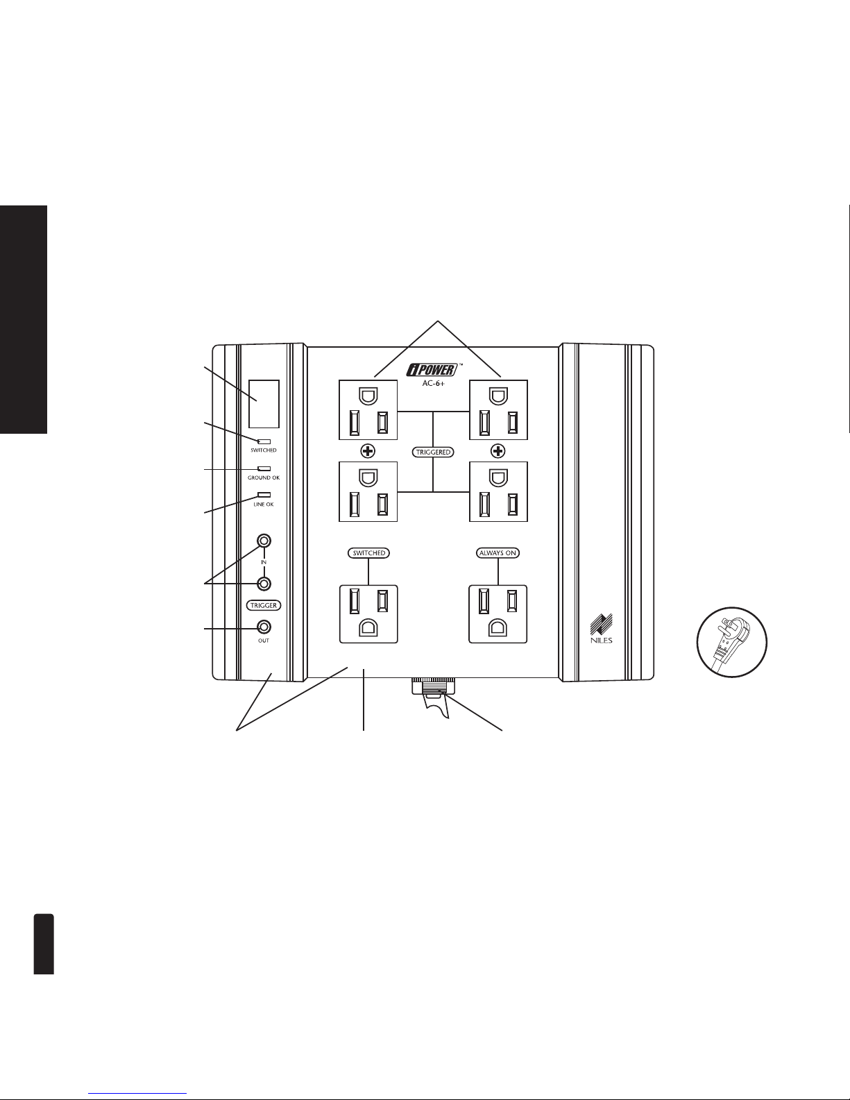
Power Button turns on
S
witched outlets and
puts Triggered outlets
into standby mode for
remote triggering.
The AC-6+ features three pairs of premium quality, wall transformer-spaced
outlets. One outlet is
Always On, one outlet is Switched on by the power
button, and two pairs are
Triggered on via either of the 12V trigger inputs.
UL 1449
2nd Edition Listed
Rugged steel chassis with
molded rubber endcaps can
be wall or floor mounted.
1
5 Amp Cir
cuit
Breaker.
Switched LED indicates the
status of the Switched
outlets and that Triggered
outlets are in standby mode.
Ground OK LED indicates
that the wall outlet wiring is
properly grounded.
Line OK LED indicates
that the wall outlet is free
of any problems such as a
polarity inversion.
Dual Zone 12V Input
Triggers
enable you to
turn on your system from
either of two components
(includes unique 12V DC
200mA wall adapter for
triggering a device).
Bus Output Trigger
enables the 12V inputs to
automate turn-on of other
iPOWER products or
protected equipment
whenever the 12V trigger
input is used.
Patent pending i3™power
protection circuitry
ensures
pr
otection time after time.
UNIT DETAILS
7
UNIT DETAILS
6 ft. industrial grade,
high-current handling
power cor
d with flat,
360º rotating plug.
Page 11

INSTALLATION OVERVIEW
8
INSTALLATION OVERVIEW
The following is an overview for installing your iPOWER™product.
• Unpack all of the contents of the AC-6+ carton.
• Plan your system and lay out all of the equipment that will be connected to the AC-6+.
• Place the AC-6+ in the location where it will be used, being sure to follow both the safety precautions listed in the front of this manual and the placement recommendations on (page 11).
DO NO
T plug the unit in yet.
• Plug each of the components into the AC-6+. You may want to make a note on paper
listing the component connected to each outlet.
• With all of the attached components in the OFF position, plug the AC-6+ into the wall.
• With the AC-6+ OFF, attach remote triggering cables (if applicable).
• Test for proper operation.
Page 12
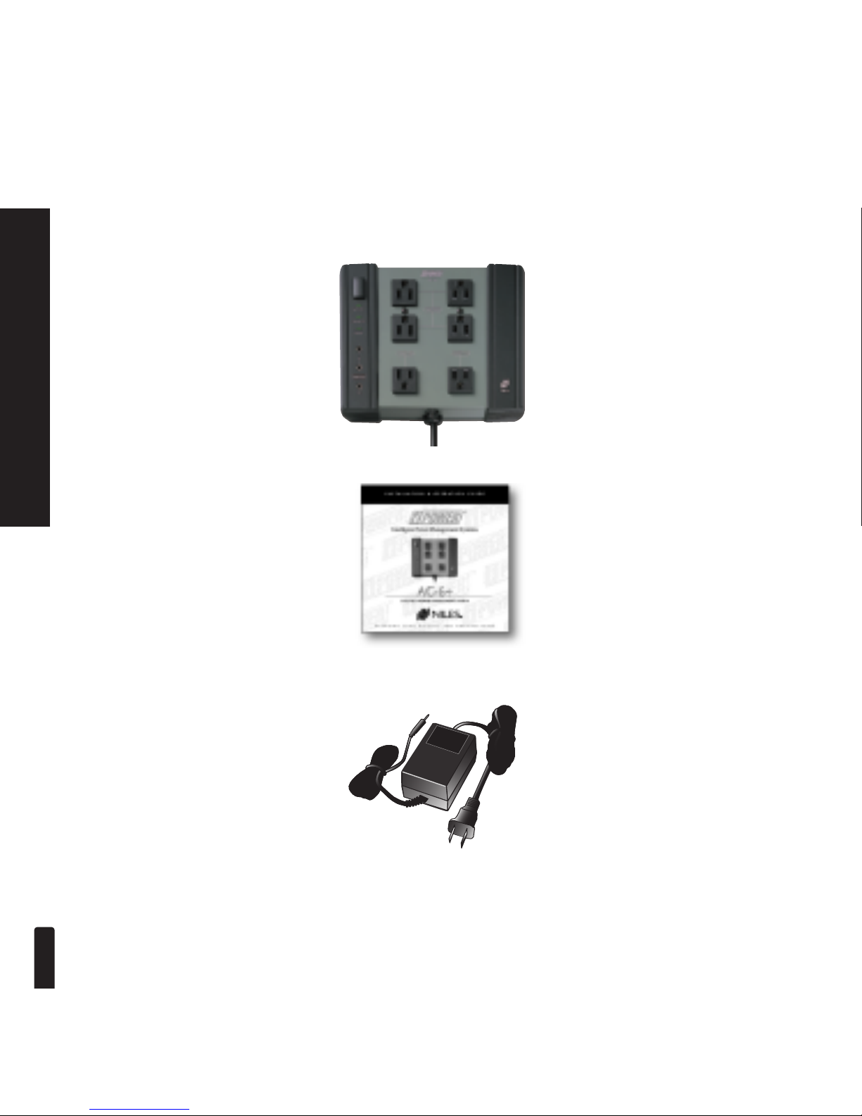
(1) AC-6+
(1) 12V, 200mA remote
trigger power supply
PACKAGE CONTENTS
PACKAGE CONTENTS
(1) Installation &
Operation Guide
9
Page 13
PLANNING YOUR SYSTEM
10
PLANNING YOUR SYSTEM
Think about which components need to work together, and place them in close proximity to one
another. You may also want to consider putting frequently handled components in the most convenient locations. Decisions about triggering options for your AC-6+ will depend on many factors
including the type of components in the system and whether they are self-controlled or part of a
multi room or whole-house system. By carefully planning the system’s architecture in advance,
your AC-6+ can be integrated into any configuration you choose.
IMPORTANT NOTE
All components in a system must be connected to an iPOWER™Power Management System in order for
the system to be protected from electrical disturbances and to realize maximum noise filtr
ation benefits.
This includes
AC power cables, coaxial connections, and telephone cables used with pa
y-per-view
systems. Failure to do this will degrade system performance and leave it vulnerable to electrical damage.
PROPER GROUNDING
Your iPOWER™product will not be able to provide surge protection or noise reduction without a proper
ground. If the
AC line in your house is properly grounded, the GROUND OK light will illuminate. If the
GROUND OK light does not illuminate, stop your installation. Check the AC connection and make sure
that the unit is plugged in properly. If the GROUND OK light still fails to illuminate, have the AC outlet
in the house checked by an electrician to diagnose the ground problem.
Page 14
Placement
It is recommended that the AC-6+ be placed in a location easily reached when manually
operating the other controls in the system. There should be a clear line of sight between the
operator and the unit to allow easy user feedback of system status. The AC-6+ should be placed on
a flat, stable shelf or platform or, if desired, it can be wall mounted. See the following section for
directions on wall mounting. IMPORTANT: Be sure to follow the "Safety Precautions" in the front
of this manual to ensure proper product performance and safety.
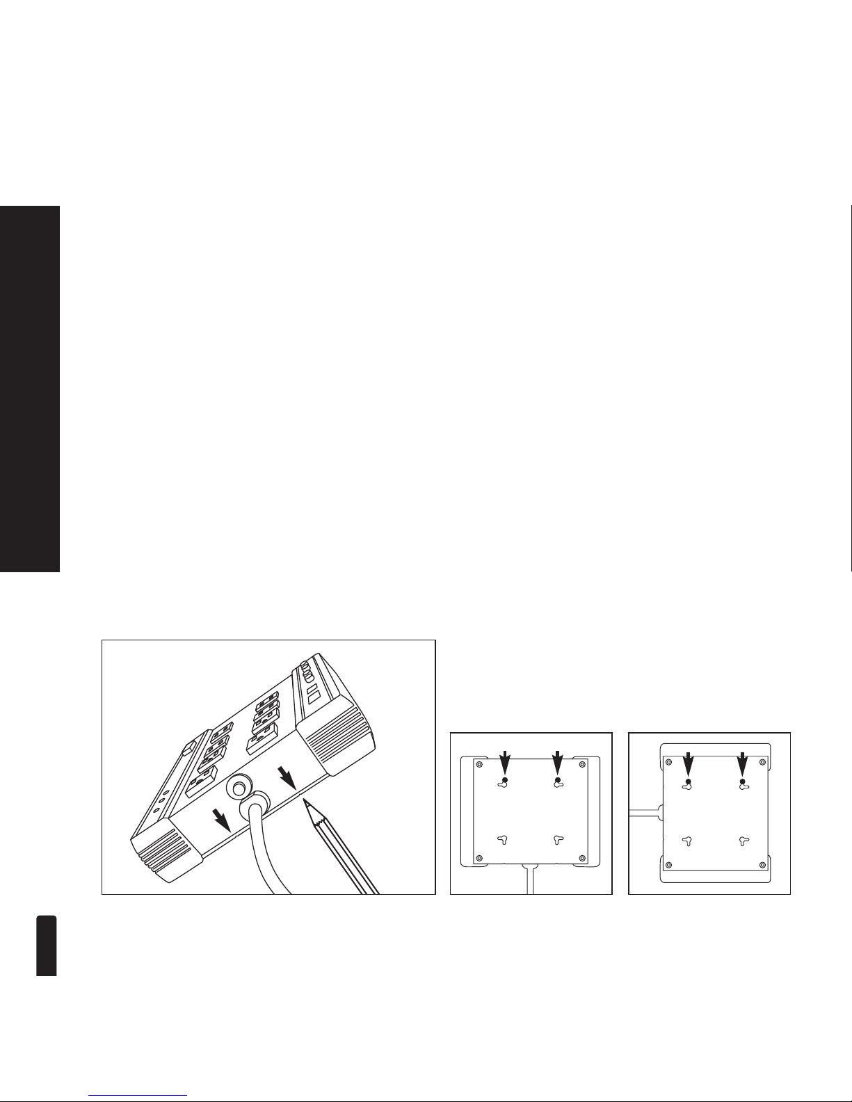
Wall Mounting
Once you have decided where your AC-6+ should be placed, you may wish to permanently mount
it in that location. Mounting screw slots are provided on all AC Series iPOWER
™
products for such
purposes. On the back of each unit you will find a series of L-shaped slots designed to
accommodate mounting screws. The L-shape of the openings allows for both vertical and
horizontal positioning of the unit. Additionally because the screw hole distances are uniform you
can rotate the unit without having to reposition the screws (see illustration).
After you’ve located the desired positioning you can mark the distance between the screw locations
using the special indents found on your AC iPOWER
™
unit (see illustration).
11
PLANNING YOUR SYSTEM
Once you’ve located your desired positioning you can
mark the screw locations using the special indents
found on your AC iPOWER
™
unit. Plus, because the
screw hole distances are uniform you can rotate the
unit without having to reposition the screws.
Page 15

12
PLANNING YOUR AC CONNECTIONS
Always On Outlet
For the Always On outlet, power will be routed to attached components at all times, regardless of
whether the Power Button on the AC-6+ is initiated or not. This outlet is appropriate for any
component that has a clock, timer, or that will be used as a master control or triggering unit for the
rest of the system. Devices such as a VCR, DBS receiver, cable TV box, or any item with a
microprocessor should use the Always On outlet.
Switched Outlet
The Switched outlet powers up the moment the Power Button is initiated. This outlet is appropriate for
devices with latching power supplies* such as some CD players, tuners, tape decks, and some televisions. If the power button on your iPOWER™unit is left permanently engaged, the Switched outlet will
function identically to the Always On outlet described above.
Triggered Outlets
The Triggered outlets enable the connected devices to power on and off automatically. When the
Power Button is initiated it places the Triggered outlets in stand-by mode. When there is 12 volts present at either of the 12V Trigger Inputs, the AC-6+ automatically turns on the Triggered outlets. When
the 12 volt signal is not present it disconnects power to the Triggered outlets. This is an immensely
valuable tool for simplifying control over one’s audio/video system. For more information, see the section “Using The Remote Trigger Feature” on page 14. T
hese outlets are appropriate for devices with
latching power supplies* such as some CD players, tuners, tape decks, and some televisions.
IMPORTANT NOTE: The Power Button must be initiated for the Trigger feature to work.
PLANNING YOUR AC CONNECTIONS
* You can tell if a component has a latching power supply by unplugging it from the wall while it is turned on,
waiting three minutes, and then plugging it back in. If the power comes back on, it is latching.
Page 16
MAKING CONNECTIONS
Connecting Devices to the AC Outlets
Be sure that the plugs are inserted all the way into the outlet to ensure a proper electrical connection.
To simplify set-up, make a note as to which components are connected to which outlets.
IMPORTANT NOTE
All components in a system must be connected to an iPOWER™Power Management System in order for
the system to be protected from electrical disturbances and to realize maximum noise filtration benefits.
This includes AC power cables, coaxial connections, and telephone cables used with pay-per-view
systems. Failure to do this will degrade system performance and leave it vulnerable to electrical damage.
13
MAKING CONNECTIONS
Page 17
14
USING THE REMOTE TRIGGER FEATURE
USING THE REMOTE TRIGGER FEATURE
Trigger Activation
Your AC-6+ has (2) Trigger Inputs and (1) Bus Trigger Output which provides a wide array of possibilities for automated turn-on and shut-off of the Triggered outlets. Each Trigger Input can be activated with 12V DC 200mA input via standard 3.5mm mini plug jacks found on the AC-6+. This
dual-trigger input configuration allows for two zone control of the system, while the single bus output allows the AC-6+ to be "daisy chained" to other iPOWER
™
products or any other
protected, triggerable device. In addition, the Trigger Output can be utilized to generate a “power
status” signal for use with compatible Niles infrared or audio/video distribution products.
Using The Trigger Inputs
NOTE:The Triggered outlets can only be triggered by the Trigger Inputs if the Power button is initiated.
Your AC-6+ has (2) Trigger Inputs which can be used for remote turn ON and turn OFF of the
Triggered outlets. The Trigger can be activated with any 12V DC trigger voltage. Many control amplifiers, preamps/receivers and system integration centers have a voltage output which can be used to
activate the AC-6+’s Trigger feature. If your system includes a control device with provisions for
remote triggering, simply connect the voltage output from the control device to the Trigger Input on
your AC-6+. If the control device has a switched outlet, plug the 12V DC 200mA Remote Trigger
Power Supply (included) into the control’s device switched outlet and the 3.5mm mini plug into one
of the AC-6+’s Trigger Inputs (see illustration, next page). Now, every time the control device’s
IMPORTANT NOTE
All components in a system must be connected to an iPOWER™Power Management System in order for
the system to be protected from electrical disturbances and to realize maximum noise filtration benefits.
This includes AC power cables, coaxial connections, and telephone cables used with pay-per-view
systems. Failure to do this will degrade system performance and leave it vulnerable to electrical damage.
Page 18
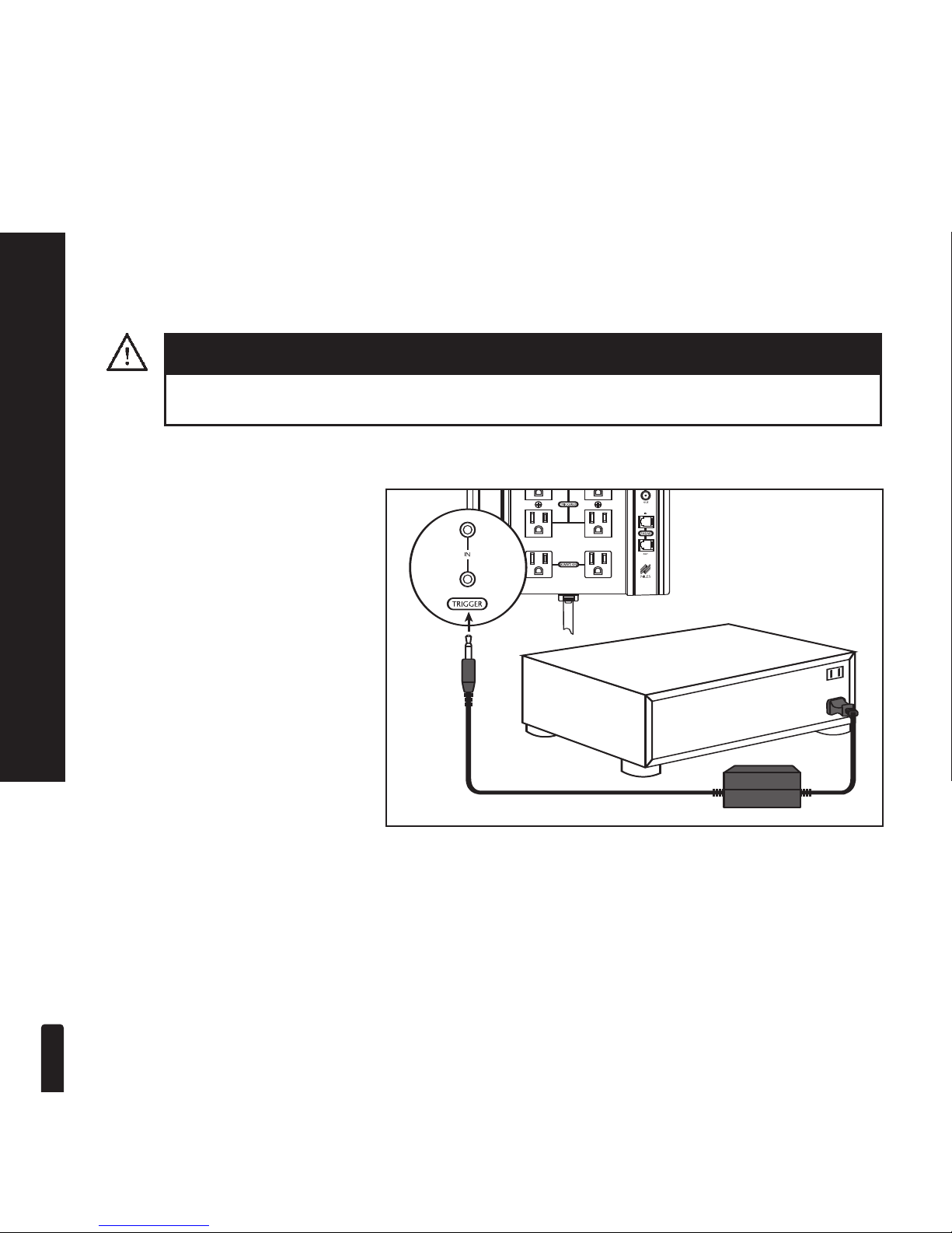
switched outlet is turned on, it will turn ON the Triggered outlets. In turn, when the control device
is shut off, it will turn OFF the triggered outlets. Since there are (2) Trigger Inputs, the AC-6+ can be
Triggered by a second control device in the same manner, allowing for multi-zone operation.
15
USING THE REMOTE TRIGGER FEATURE
IMPORTANT NOTE
IMPORTANT! The control device must be plugged into the AC-6+ to ensure proper protection.
The illustration offers one example of automating the turn on and
turn off of the Triggered outlets.
The 12V DC 200mA Remote Trigger Power Supply (included) is
plugged into the switched outlet
of a preamp/receiver. Its 3.5mm
jack plugs into one of the Trigger
Inputs on the AC-6+.
Page 19
16
Using The Trigger Output
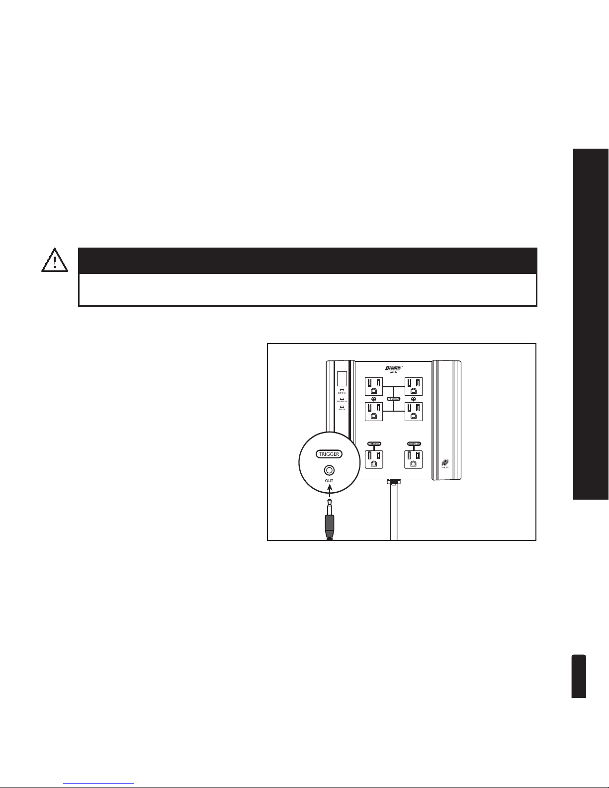
The AC-6+ has a bus Trigger Output jack which provides a convenient pass through from the remote
Trigger Input. Simply connect the output jack on the AC-6+ to any protected triggerable device, and
the input voltage that controls the Triggered outlets will be passed through the AC-6+ to another
device.
Additional Remote Trigger Power Supplies
If you require additional Remote Trigger Power Supplies, they can be obtained from your authorized Niles dealer (Stock# FG00665).
IMPORTANT NOTE
IMPORTANT! The control device must be plugged into the AC-6+ to ensure proper protection.
The Trigger Output can be used to pass the
input trigger voltage through the AC-6+ to
automatically turn on additional protected
equipment or iPOWER products.
USING THE REMOTE TRIGGER FEATURE
Page 20

17
TROUBLESHOOTING
AC-6+ does not power-up.
There is no power to the
connected equipment.
Trigger lines are attached, but the
AC-6+’s trigger outlets will not
power up via the Trigger input.
The GROUND OK light on the
front panel of the AC-6+ does not
light up.
The LINE OK indicator on the
front panel of the AC-6+ does not
light up.
• Check that the unit is plugged in and that there is power to the
outlet.
• Check the AC-6+’s circuit breaker located by the power cord
and reset if necessary.
• First, re-check the trigger lines to ensure a positive connection.
then check that the trigger is going to the TRIGGER IN jack on
the AC-6+.
• If all connections are properly made and the AC-6+ fails to
respond, it is most likely that the trigger signal has too low a
voltage (below 12V). Check the trigger source to be sure that
the signal is 12V DC 200mA.
• Check that the Power Button is initiated. The Triggered outlets
will not function if the Power button is not in the “ON” position.
•This indicates that the wall outlet is not properly grounded or
possibly another type of line problem. Without a proper
ground, your AC-6+ will not provide power protection.
1. STOP YOUR INSTALLATION. Check the AC connection
and make sure that the AC-6+ is plugged in properly. If the
GROUND OK light still fails to illuminate, have the AC
outlet in the house checked by an electrician to diagnose
the problem.
2. DO NOT operate your AC-6+ without a proper ground.
•This indicates that the wall outlet has a line problem such as
polarity inversion. This is common, especially in older homes.
DO NOT operate the AC-6+ with a line problem. Call your
electrician to have the line repaired.
TROUBLESHOOTING
SYMPTOM
POSSIBLE CAUSES AND TEST PROCEDURE
Page 21

18
TROUBLESHOOTING
TROUBLESHOOTING (continued)
• This indicates that either the wall outlet is not properly grounded, or the wall outlet has a line problem such as a polarity
inversion, (or both). See the above two items for more information.
• Your AC-6+ is equipped with a 15 Amp circuit breaker to provide overload protection. This breaker will allow up to 1800
watts of power to pass through the AC-6+ to your
components. If the breaker continues to trip after being reset
several times, there may be a short in the system. If no short is
apparent, or the problem is intermittent, this indicates that the
components are drawing more than the 1800 watts the
AC-6+ can supply. Check with your Niles dealer or installer to
see what other iPOWER
™
products can be used in addition to
the AC-6+ to provide sufficient power for your system.
• Many components will create "thumps," "clicks," and "pops"
when they are first turned on. This can happen while their internal power supply "settles in," which usually only takes a few
seconds or so. This is common, and while annoying, it usually
will not harm loudspeakers. Niles offers several iPOWER
™
models with features designed to prevent this condition. See your
Niles dealer for more information.
POSSIBLE CAUSES AND TEST PROCEDURE
Both the LINE OK indicator and
the GROUND OK light on the
front panel of the AC-6+ do not
light up.
The circuit breaker on the
AC-6+ continues to trip.
There is an audible "thump,"
"click," or "pop," coming from my
loudspeakers during the powerup function of my AC-6+.
SYMPTOM
Page 22

19
SPECIFICATIONS
SPECIFICATIONS
AC OUTLETS TECHNICAL SPECIFICATIONS
UL 1449 Clamping Rating ............................330 Volts (lower value is better)
ANSI/IEEE 100 kHz Ring Wave Test ............<40 volts above peak standard line voltage
Response time ..............................................Instantaneous [<1 nanosecond (<1 billionth of a second)]
Surge Voltage ................................................Tested to 6,000 Volts
Energy dissipation ........................................1550 Joules
Line voltage ..................................................120VAC 15A, 50/60 Hz
Peak impulse current ....................................100,000 Amps
Protection Modes..........................................Line to Neutral, Line to Ground, Neutral to Ground
EMI/RFI noise reduction ..............................Up to 60dB (99.9%) 100 kHz to 100 MHz
TRIGGER CIRCUIT
Trigger Inputs ................................................12V DC 200mA
Trigger Output................................................Direct pass-through from 12V DC Trigger Inputs
Connections ..................................................3.5 mm jacks
TRIGGER WALL ADAPTER
12V DC 200mA with in-line power supply and 3.5 mm plug
Net Weight
..................................................3 lbs.
6 oz.
Dimensions ............................................Width: 8-1/4"; Height: 6-3/8"; Depth: 2"
Page 23

©2005 Niles Audio Corporation. All rights reserved. Niles, the Niles logo, and Blending High Fidelity
and Architecture are registered trademarks of Niles Audio Corporation. iPOWER, i3, iDefinition and
iQ ar
e trademarks of Niles Audio Corporation. All other trademarks are the property of their respective owners. Because we constantly strive to improve our products, Niles reserves the right to
change product specifications without notice. The technical and other information contained herein
is not intended to set forth all technical and other specifications of Niles pr
oducts. Additional
information can be obtained on-line at www
.nilesaudio.com or by calling Niles at 1-800-289-4434.
Printed in USA. 04/05 DS00251B
449E
1449 Second Edition
E195090
Niles Audio Corporation
12331 S.W. 130 Street
Miami, Florida 33186
Tel: (305) 238-4373
Fax: (305) 238-0185
www.nilesaudio.com
 Loading...