

Page 1

WT-
WT-
En
Fr
Wireless Transmitter
C
L
C
WT-
A
/V
OUT
D
C
IN
S
CK
LO
2WT-
2
LINKBUSY
LINKBUSY
POWER
POWER
Es
User's Manual
Page 2

Wireless Transmitter
WT-2
WT-2
C
L
C
S
A
/
V
O
U
T
D
C
IN
Y
Y
S
S
U
U
B
B
LINK
LINK
R
R
E
E
POW
LOCK
POW
En
User’s Manual
Page 3

Trademark Information
Macintosh and Mac OS are trademarks of Apple Computer, Inc. Microsoft and Win dows are reg is tered trade marks
of Microsoft Corporation. All oth er trade names men tioned in this man u al or the oth er doc u men ta tion pro vid ed with
this Nikon prod uct are trade marks or reg is tered trade marks of their re spec tive holders.
Apple Public Source License
This product includes Apple mDNS source code that is subject to the terms of the Apple Public Source License located
at URL http://developer.apple.com/darwin/.
Portions Copyright (c) 1999-2004 Apple Computer, Inc. All Rights Reserved.
This fi le contains Original Code and/or Modifi cations of Original Code as defi ned in and that are subject to the Apple
Public Source License Version 2.0 (the 'License'). You may not use this fi le except in compliance with the License.
Please obtain a copy of the License at http://www.opensource.apple.com/apsl/ and read it before using this fi le.
The Original Code and all software distributed under the License are distributed on an 'AS IS' basis, WITHOUT WARRANTY OF ANY KIND, EITHER EXPRESS OR IMPLIED, AND APPLE HEREBY DISCLAIMS ALL SUCH WARRANTIES, INCLUDING WITHOUT LIMITATION, ANY WARRANTIES OF MERCHANTABILITY, FITNESS FOR A PARTICULAR PURPOSE,
QUIET ENJOYMENT OR NON-INFRINGEMENT. Please see the License for the specifi c language governing rights and
limitations under the License.
Page 4
For Your Safety
To prevent damage to your Nikon product or injury to yourself or to others, read the
following safety precautions in their entirety before using this equipment. Keep these
safety instructions where all those who use the product will read them.
The consequences that could result from failure to observe the precautions listed in this
section are indicated by the following symbol:
This icon marks warnings, information that should be read before using this
Nikon product to prevent possible injury.
WARNINGS
Do not disassemble
Failure to observe this precaution could result in fi re, electric shock, or other injury. Should the product break
open as the result of a fall or other accident, disconnect the camera power source and take the product to a
Nikon-authorized service representative for inspection.
Turn camera off immediately in the event of malfunction
Should you notice smoke or an unusual smell coming from the equipment, immediately remove the battery
from the camera, taking care to avoid burns. Continued operation could result in injury. After removing the
battery, take the equipment to a Nikon-authorized service representative for inspection.
Keep dry
Do not immerse in or expose to water or rain. Failure to observe this precaution could result in fi re or electric
shock.
Do not use in the presence of fl ammable gas
Failure to observe this precaution could result in explosion or fi re.
Do not handle with wet hands
Failure to observe this precaution could result in electric shock.
Keep out of reach of children
Failure to observe this precaution could result in injury.
Follow the instructions of hospital and airline personnel
This device emits radio frequency radiation that could interfere with medical or navigational equipment. Do
not use this device in a hospital or on board an airplane without fi rst obtaining the permission of hospital
or airline staff.
Do not expose to high temperatures
Do not leave the device in a closed vehicle under the sun or in other areas subject to extremely high temperatures. Failure to observe this precaution could result in fi re or in damage to the casing or internal parts.
Observe caution when using the WA-E1
When using the WA-E1 extended range antenna (available separately), be careful not to put the tip of the
antenna in your eye accidentally. Failure to observe this precaution could result in blindness or other visual
impairment.
i
Page 5

Notices
• No part of the manuals included with
this product may be reproduced, transmitted, transcribed, stored in a retrieval
system, or translated into any language
in any form, by any means, without
Nikon’s prior written permission.
• Nikon reserves the right to change the
specifi cations of the hardware and software described in these manuals at any
time and without prior notice.
• Nikon will not be held liable for any
damages resulting from the use of this
product.
• While every effort has been made to
ensure that the information in these
manuals is accurate and complete, we
would appreciate it were you to bring
any errors or omissions to the attention
of the Nikon representative in your area
(address provided separately).
Notice for Customers in the U.S.A.
U.S.A. Federal Communications Commission (FCC)
Declaration of Conformity
This device complies with Part 15 of the FCC rules. Operation of the device is subject to
the following two conditions: (1) this device may not cause harmful interference, and
(2) this device must accept any interference received, including interference that may
cause undesired operation.
Products that contain a radio transmitter
are labeled with FCC ID and may also carry
the FCC logo.
FCC Radio Frequency Interference Statement
This equipment has been tested and found to comply with the limits for a Class B digital device, pursuant to Part 15 of the FCC rules. These limits are designed to provide
reasonable protection against harmful interference in a residential installation. This
equipment generates, uses, and can radiate radio frequency energy and, if not installed
and used in accordance with the instructions, may cause harmful interference to radio
communications. However, there is no guarantee that interference will not occur in a
particular installation. If this equipment does cause harmful interference to radio or
television reception, which can be determined by turning the equipment off and on,
the user is encouraged to try to correct the interference by one or more of the following measures:
• Reorient or relocate the receiving antenna.
• Increase the separation between the equipment and receiver.
• Connect the equipment into an outlet on a circuit different from that to which the
receiver is connected.
• Consult the dealer or an experienced radio/television technician for help.
WT-2A
ii
Page 6

FCC Radiation Exposure Statement
The available scientifi c evidence does not show that any health problems are associated with using low power wireless devices. There is no proof, however, that these low
power wireless devices are absolutely safe. Low power Wireless devices emit low levels
of radio frequency energy (RF) in the microwave range while being used. Whereas high
levels of RF can produce health effects (by heating tissue), exposure to low level RF that
does not produce heating effects causes no known adverse health effects. Many studies of low level RF exposures have not found any biological effects. Some studies have
suggested that some biological effects might occur, but such fi ndings have not been
confi rmed by additional research. The Wireless Transmitter (WT-2A) has been tested and
found to comply with the Federal Communications Commission (FCC) guidelines on
radio frequency energy (RF) exposures. The maximum SAR levels tested for the Wireless
Transmitter (WT-2A) has been shown to be 0.267 W/kg at Head.
This device should not be co-located or operated with any other antenna or transmitter.
CAUTION
Modifi cations
The FCC requires the user to be notifi ed that any changes or modifi cations made to
this device that are not expressly approved by Nikon Corporation may void the user’s
authority to operate the equipment.
Notice for customers in the State of California, U.S.A.
WARNING: Handling the cord on this product will expose you to lead, a chemical known
to the State of California to cause birth defects or other reproductive harm. Wash
hands after handling.
Nikon Inc.,
1300 Walt Whitman Road, Melville, New York
11747-3064, U.S.A.
Tel.: 631-547-4200
Notice for customers in Canada
CAUTION
This class B digital apparatus meets all requirements of the Canadian Interference
Causing Equipment Regulations.
ATTENTION
Cet appareil numérique de la classe
B respecte toutes les exigences du
Règlement sur le matériel brouilleur du
Canada.
iii
Page 7

Table of Contents
For Your Safety............................................i
Notices ......................................................ii
Notice for Customers in the U.S.A.............ii
Notice for customers in Canada ..............iii
Introduction.......................................... 1
Supported Protocols ..................................2
ftp...........................................................2
PTP / IP .....................................................2
Parts of the WT-2.......................................3
Setup ....................................................4
Step 1—Connect the WT-2........................4
Step 2—Select PTP....................................5
Uploading Images: ftp Mode................ 5
Setup Using the Connection Wizard ..........6
Connecting to the Server...........................9
Uploading Images ...................................10
Interrupting Transmission .......................11
Icon ......................................11
The
Network Status......................................12
Controlling the Camera: PTP / IP Mode
Installing Pairing Software.......................14
Setup Using the Connection Wizard ........15
Pairing.....................................................17
Connecting to the Computer ...................20
Controlling the Camera ...........................21
Network Status......................................22
Menu Guide........................................ 24
Wireless LAN system ...............................24
Mode.......................................................24
Settings ...................................................24
Network Settings...................................25
Pairing Options (PTP / IP Mode Only) .......36
Auto Send (FTP Mode Only) ...................37
Delete After Send (FTP Mode Only).........37
Send File As (FTP Mode Only).................38
Send Folder (FTP Mode Only) .................38
Deselect All (FTP Mode Only)..................38
... 14
Appendices......................................... 39
Installing Pairing Software.......................39
Installation (Windows XP)......................39
Installation (Mac OS X) ..........................41
Sample ftp Settings .................................42
Preparation............................................42
Building a Network................................43
Confi guring the Server ...........................43
Confi guring the Wireless LAN Adapter....45
Confi guring the WT-2 .............................46
Uploading Pictures.................................48
Troubleshooting.......................................50
Glossary...................................................51
Specifi cations ..........................................54
Index .......................................................55
iv
Page 8
Introduction
Thank you for purchasing a WT-2 or WT-2A wireless transmitter for compatible Nikon digital cameras. The WT-2 is for use only in Austria, Belgium,
Denmark, Finland, France, Germany, Greece, Italy, Japan, the Netherlands,
Portugal, Spain, Sweden, Switzerland, and the United Kingdom. The WT-2A
is for use only in Canada and the United States of America. The principal difference between the WT-2 and WT-2A is in the number of channels supported
(see pg. 54); unless otherwise stated, all references to the WT-2 also apply to
the WT-2A.
This manual describes how to connect the WT-2 and control the camera from
a computer running Nikon Capture 4 version 4.2 or later (available separately)
or transmit images to a server over a wireless LAN. Before using the WT-2, be
sure to read the notices and warnings on pages i–iii.
The following symbols and conventions are used throughout this manual:
This icon marks cautions, information that should be read before use
to prevent damage to the WT-2.
This icon marks tips, additional
information that may be helpful
when using the WT-2.
Background Knowledge
This manual assumes basic knowledge of ftp servers and wireless local area networks
(LAN). For more information on installing, confi guring, and using devices in a wireless
network, contact the manufacturer or network administrator.
Life-Long Learning
As part of Nikon’s “Life-Long Learning” commitment to ongoing prod uct sup port and
ed u ca tion, con tin u al ly-updated information is avail able on-line at the following sites:
• For users in the U.S.A.: http://www.nikonusa.com/
• For users in Europe: http://www.europe-nikon.com/support
• For users in Asia, Oceania, the Middle East, and Africa: http://www.nikon-asia.com/
Visit these sites to keep up-to-date with the latest product in for ma tion, tips, an swers to
fre quent ly-asked ques tions (FAQs), and gen er al advice on digital imaging and pho tog ra phy. Ad di tion al information may be available from the Nikon rep re sen ta tive in your
area. See the URL below for contact in for ma tion:
http://nikonimaging.com/
This icon marks notes, information
that should be read before using
the device.
This icon indicates that more information is available elsewhere in this
manual.
1
Page 9
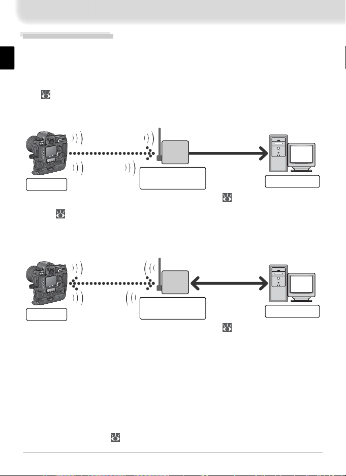
Supported Protocols
The WT-2 wireless transmitter is a wireless LAN adapter that allows the camera to be controlled remotely from a computer running Nikon Capture 4 version 4.2 or later (available separately) or photographs to be upload to an ftp
server over a wireless LAN. The WT-2 supports the following protocols:
ftp ( 5)
New photographs and photographs stored on the camera memory card can
be uploaded to an ftp server via a wireless LAN.
C
L
C
S
A
/
V
O
U
T
DC
I
N
BUSY
BUSY
K
K
IN
IN
L
L
POWER
POWER
K
C
O
L
WT-2
Wireless LAN
access point
*
ftp server
* Infrastructure mode only; not required in ad-hoc mode ( 27).
PTP / IP ( 14)
The camera can be controlled from a computer on the same network and pictures saved directly to the computer hard disk using Nikon Capture 4 version
4.2 or later (available separately; connection via router not supported).
C
L
C
S
A
/
V
O
U
T
DC
I
N
BUSY
BUSY
K
K
IN
IN
L
L
POWER
POWER
K
C
O
L
WT-2
Wireless LAN
access point
*
Computer
* Infrastructure mode only; not required in ad-hoc mode ( 27).
An environment with a wireless LAN is required to use the WT-2. An ftp server
is required for ftp. Operation has been confi rmed on the following systems:
• ftp: Windows Server 2003, Windows 2000 Server, Windows XP Professional,
Windows 2000 Professional, Mac OS X Server, Mac OS X. Internet ftp connections and ftp servers running third-party software are not supported.
• PTP / IP: Windows XP Professional, Windows XP Home Edition, Mac OS X
(version 10.3 or later).
For the latest information on supported operating systems, see the Nikon
website for your area ( 1).
2
Page 10
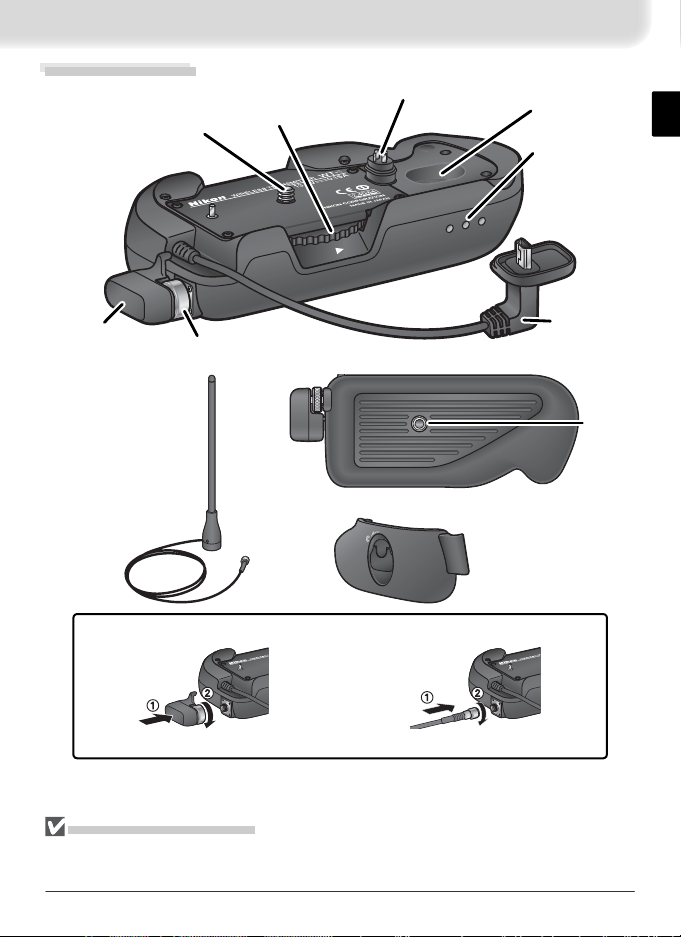
Parts of the WT-2
Mounting
screw
Knob
LOCK
Power
contact
POWER
Housing
Status LEDs:
POWER
(green), LINK
(orange),
BUSY
LINK
BUSY (green)
Standard antenna
(WA-S1)
Antenna
connector
Tripod
USB cable
WA-E1 extended
socket
range antenna with
tripod mount
(available separately)
BL-2 battery-chamber
cover (for camera
battery chamber)
Attaching an antenna
Standard antenna (WA-S1) WA-E1 extended range antenna
Reorienting the Antenna
Before reorienting the WA-S1, unscrew it from the antenna connector. When using the
WA-E1 (available separately), be careful not to kink or tug the cable.
3
Page 11
LO
C
K
POWERPOW
ER
LO
CK
POWERPOW
ER
LO
C
K
POW
ER
L
IN
K
B
U
S
Y
POW
ER
L
IN
K
B
U
S
Y
Setup
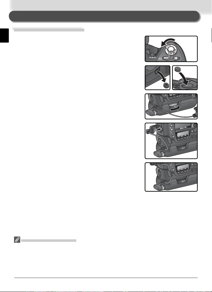
Step 1—Connect the WT-2
Tu rn the camera off.
1
Remove the cover protecting the camera power
2
contact. The cover can be stored in the housing
on the WT-2.
Place the camera on the WT-2 and rotate the knob
3
in the direction shown to fasten the WT-2 to the
camera tripod mount.
Open the camera USB connector cover and con-
4
nect the USB cable to the USB connector.
Pass the cable over the guide on the BL-2 battery-
5
chamber cover.
Disconnecting the WT-2
To disconnect the WT-2:
1 Turn the camera off.
2 Disconnect the USB cable.
3 Rotate the knob clockwise to unscrew the WT-2 from the camera tripod mount.
4 Replace the cover on the camera power contact.
4
Page 12
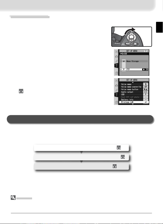
Step 2—Select PTP
The camera must be in PTP mode to communicate with the WT-2.
Tu rn the camera on.
1
Set the USB option in the camera setup menu to
2
PTP.
The Wireless LAN option in the camera setup
menu will now be available. See “Menu Guide”
24) for details.
(
Uploading Images: ftp Mode
In ftp mode, photographs can be uploaded to an ftp server over a wireless
network. The principal steps involved in connecting to an ftp server for the
fi rst time are as follows:
1—Adjusting Settings ........................................... 6–8
2—Connecting to the Server.................................... 9
3—Uploading Images ....................................... 10–11
Step 1 can be omitted once the WT-2 has been set up for connection to a
particular server.
Firewalls
ftp mode uses TCP ports 20 and 21. It may be necessary to adjust fi rewall settings
before connecting to a server behind a fi rewall.
5
Page 13
Setup Using the Connection Wizard
First-time setup can be completed with the help of the Connection Wizard.
Before starting the Connection Wizard, make sure that network is active and
the destination ftp server is running. To prevent changes to settings from being lost should the camera monitor turn off automatically, use the optional AC
adapter or choose the maximum camera monitor off delay.
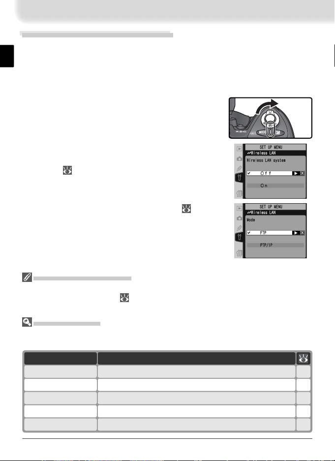
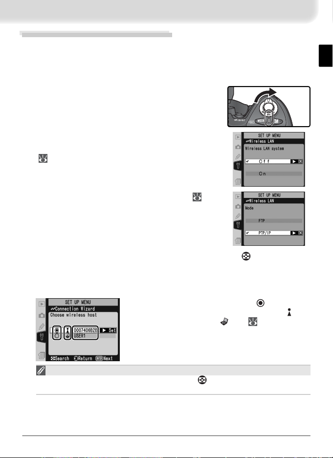
Tu rn the camera on.
1
Check that Off is selected for the Wireless LAN >
2
Wireless LAN system option in the camera setup
menu ( 24).
Select FTP for Wireless LAN > Mode ( 24).
3
Wireless Network Settings
For information on adjusting wireless network settings without using the Connection
Wizard, see “Menu Guide” ( 26–35). See page 25 for information on loading settings fi les created with a computer.
ftp Mode Settings
In addition to the settings made with the Connection Wizard, the following options are
available in ftp mode:
DescriptionOption
Auto send
Delete after send?
Upload photos to server as they are taken.
Delete photos from camera memory card after upload.
37
37
38Send NEF + JPEG images as JPEG only or as NEF and JPEG.Send fi le as:
38Upload all photos in selected folder.Send folder
38Deselect all images selected for upload.Deselect all?
6
Page 14
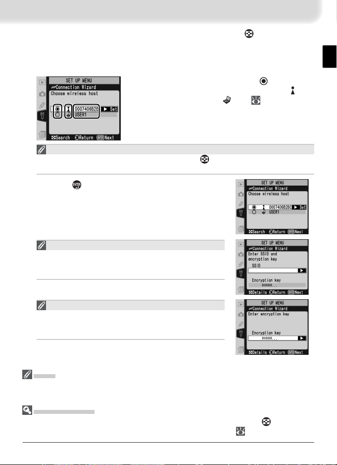
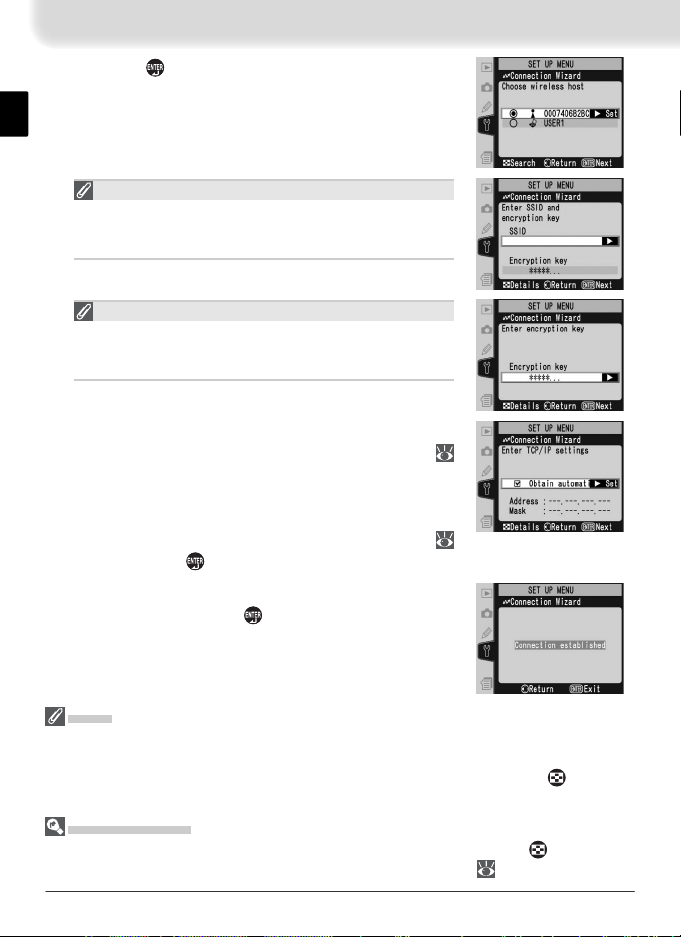
In the top level of the wireless LAN menu, press the button to start
쐃쐃쐇쐇쐋
4
the Connection Wizard. A list of available connections will be displayed.
Press the multi selector up or down to highlight the desired connection
and press the multi selector to the right to select it.
쐃 Selected connection is marked with
쐇 Infrastructure connections are marked with icon,
ad-hoc connections with
쐋 SS-ID (not displayed if SS-ID is unavailable).
쐋
Connection Not Available
If the desired connection is not listed, press the button to search again. If the
connection still can not be found, check settings on the network.
Press the button.
icon ( 27).
icon.
5
SS-ID
If prompted for an SS-ID, press the multi selector to the
right and enter the connection SS-ID as described on
page 26.
Encryption Key
If prompted for an encryption key, press the multi selector to the right and enter a key as described on page
27.
Errors
If an error is displayed, press the multi selector to the left to return to the previous dialog
and enter a valid value for the affected setting.
Related Settings
To access advanced settings when entering data in steps 5–9, press the button. The
related section of the network settings menu will be displayed ( 26–35).
7
Page 15
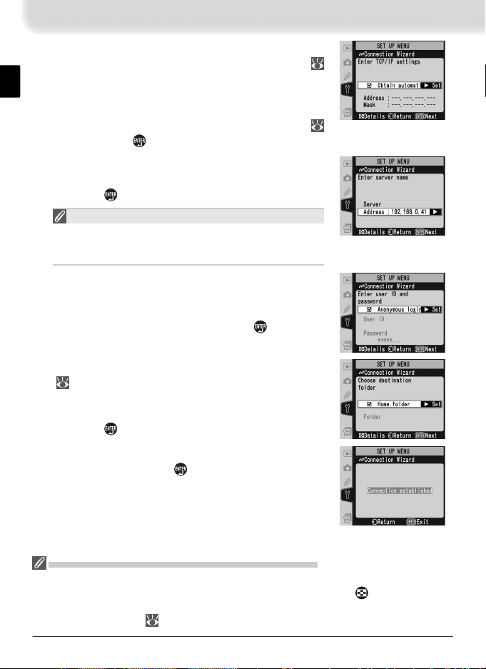
If the network is confi gured to supply an IP ad-
6
dress automatically by DHCP server or Auto IP (
51), press the multi selector to the right to select
Obtain automatically. If the network requires a
fi xed IP address or subnet mask, enter the information supplied by the network administrator (
28). Press the
Press the multi selector to the right and enter the
7
server URL or IP address as described on page 32.
Press the button to proceed to Step 8.
“UNABLE TO LOCATE SERVER”
If this error is displayed, press the multi selector to the
left to return to Step 6 or 7 and enter a valid IP address
and server name.
If anonymous login is permitted, press the multi
8
selector to the right to select Anonymous
login. Otherwise enter a user ID and password
as described on page 33. Press the button to
proceed to Step 9.
To upload images to the server’s home directory
9
( 34), press the multi selector to the right to
select Home folder. To choose a different folder,
enter the folder name as described on page 34.
Press the button to proceed to Step 10.
The dialog shown at right is displayed when setup
10
is complete. Press the button to exit the wizard
and return to the wireless LAN menu.
button to proceed to Step 7.
“WIRELESS ERROR,“ “TCP / IP ERROR,” “FTP ERROR“
The above errors indicate that the associated wireless network options are set incorrectly. After checking settings for the host or access point, press the button to restart
the Connection Wizard and adjust camera settings to match. For more information, see
“Sample ftp Settings” ( 42).
8
Page 16
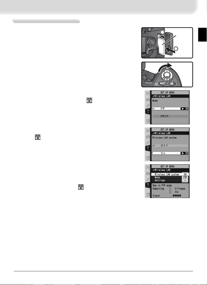
Connecting to the Server
1
2
Tu rn the camera off and insert the memory card
1
containing the pictures to be sent.
Tu rn the camera on.
2
Select FTP for the Wireless LAN > Mode option
3
in the camera setup menu ( 24).
Select On for Wireless LAN > Wireless LAN sys-
4
tem ( 24).
Confi rm that “Now in FTP mode” is shown
5
in the top level of the wireless LAN menu. For
information on what to do if an error is displayed,
see “Troubleshooting” ( 50).
Reverse
side
9
Page 17
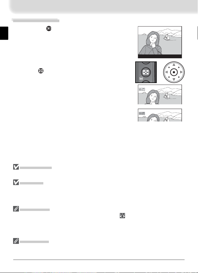
Uploading Images
Press the button to view pictures on the
1
memory card. Display the fi rst picture to be sent
in single-image playback or highlight it in the
thumbnail list.
100-1
Press the center of the multi selector while press-
2
ing the button. The image will be marked with
a white “send” icon and transmission will begin
immediately. During upload, images are marked
with a green “sending” icon. Repeat this process
to send additional images (pictures will be sent in
the order selected).
Images that have been successfully uploaded are
marked with a blue “sent” icon.
During Upload
Do not remove the memory card from the camera during upload.
File Names
If the destination folder on the ftp server contains fi les with the same names as images
selected for upload, the fi les on the server will be replaced by the images uploaded
from the camera.
Loss of Signal
Transmission may be interrupted if the signal is lost ( 13). Transmission can be resumed by turning the camera off and then on again, activating the camera exposure
meters, or selecting On for Wireless LAN > Wireless LAN system once the signal is
restored.
Voice Memos
Voice memos can not be uploaded separately, but will be included when the associated
pictures are transmitted.
+
10
Page 18
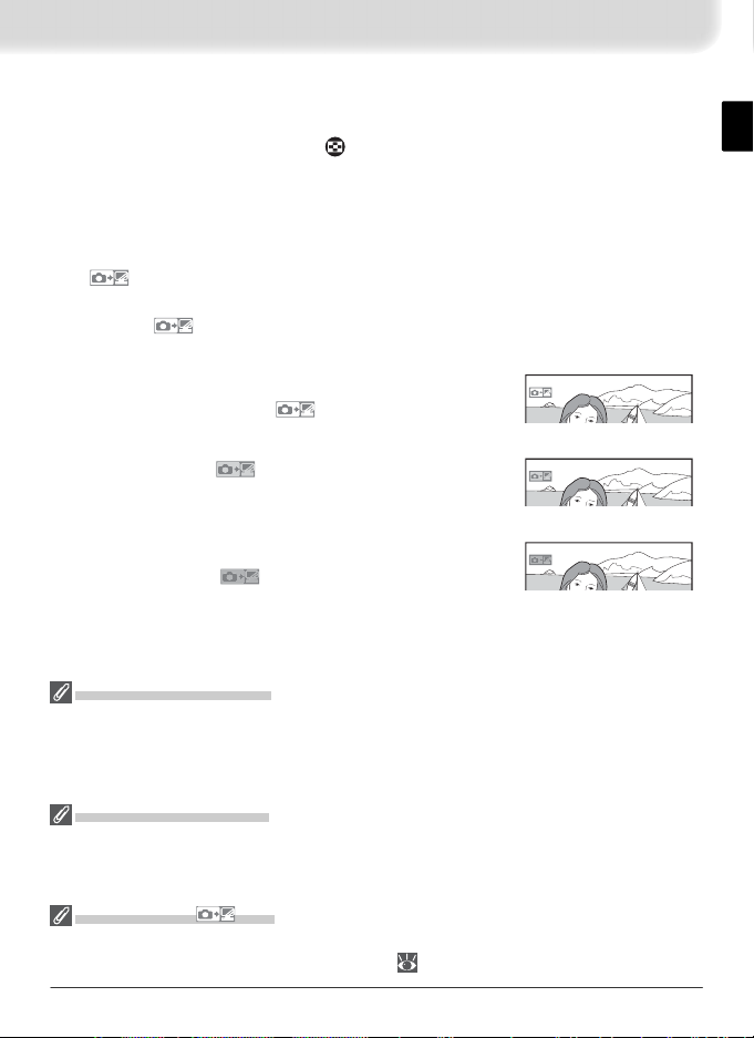
Interrupting Transmission
To cancel transmission of images marked with a white “send” icon or green
“sending” icon, select the images during playback and press the center of the
multi selector while pressing the
button. The icon will be removed. Any of
the following actions will also interrupt transmission:
• Turning the camera off
• Choosing Off in the Wireless LAN > Wireless LAN system menu
• Selecting Yes for Wireless LAN > Settings > Deselect all?
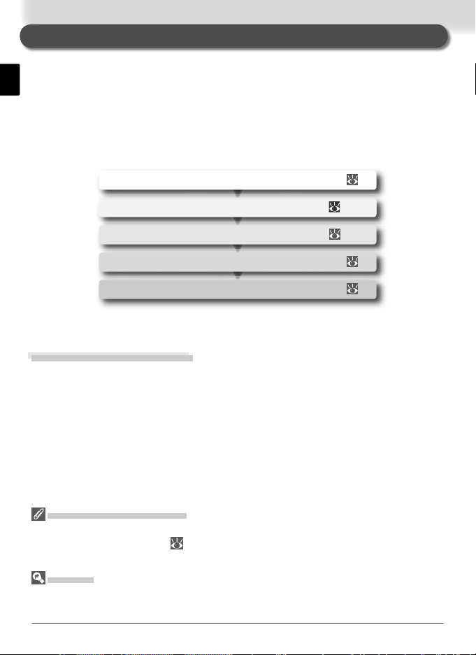
The
Icon
The status of images selected for uploaded is indicated during playback by the
color of the icon.
White: “Send”
Images that have been selected for upload are marked
with a white “send” icon ( ).
Green: “Sending”
During upload, the icon is displayed in green.
Blue: “Sent”
Images that have been uploaded successfully are
marked with a blue icon.
Tur ning the Camera Off
“Send” marking will be saved if the camera is turned off or Off is selected for Wireless
LAN > Wireless LAN system while transmission is in progress. Transmission of images
marked with a “send” icon will resume when the camera is turned on, the shutter-release
button is pressed halfway, or On is selected for Wireless LAN > Wireless LAN system.
Resuming Transmission
When transmission resumes, the fi le that was being transmitted when the interruption
occurred will be uploaded under a new name created by adding a number between 1
and 9 in front of the extension (e.g., “DSC_0001-1.jpg”).
Removing the Icon
“Send,” “sending,” and “sent” icons can be removed from all images by selecting Yes
for Wireless LAN > Settings > Deselect all? ( 38).
11
Page 19
Network Status
POWER
L
IN
K
BUSY
POWER
L
IN
K
BUSY
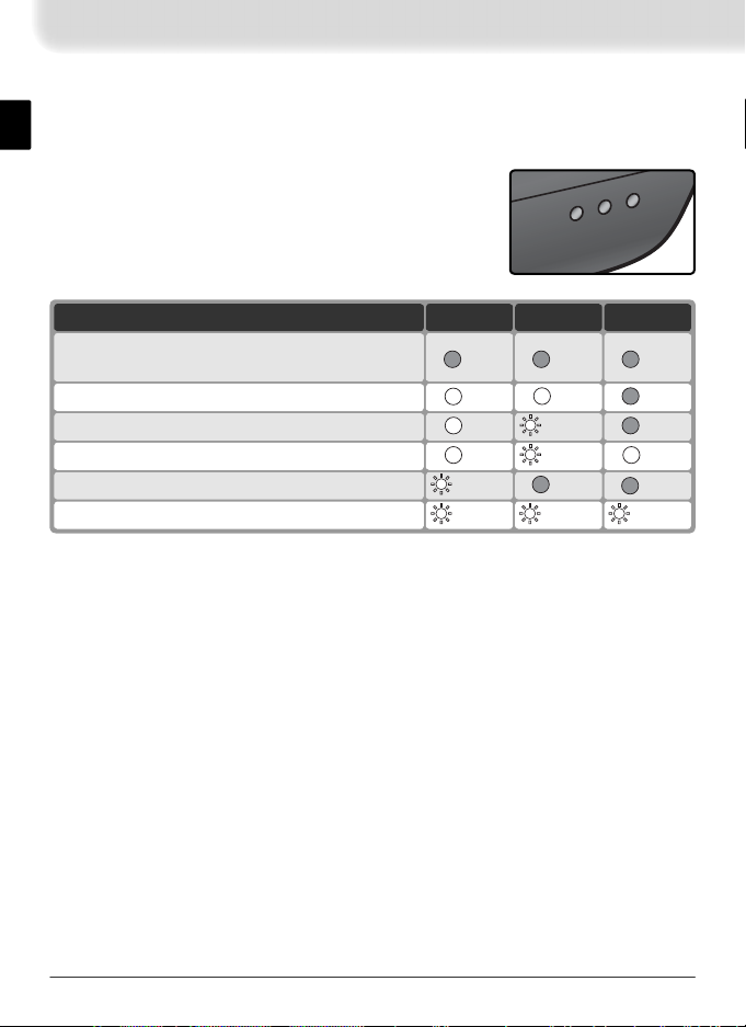
The status of the link between the server and the WT-2 is shown by the status
LEDs and by the display in the top level of the wireless LAN menu.
The Status LEDs
The POWER LED lights when the WT-2 is receiving
power from the camera.
Signal quality is shown by
the LINK LED: the faster the LED blinks, the better the
signal and the faster data can be transmitted. The
BUSY LED lights while data are being sent.
BUSYLINKPOWERStatus
Camera or exposure meters off, or Off selected
for Wireless LAN > Wireless LAN system
Connecting to ftp server
(on)
(off) (off) (off)
(on) (off)
(off) (blinks) (on)Waiting to send data
(on) (blinks) (on)Sending data
(off) (off) (blinks)Connection error
(blinks) (blinks) (blinks)WT-2 hardware malfunction
12
Page 20
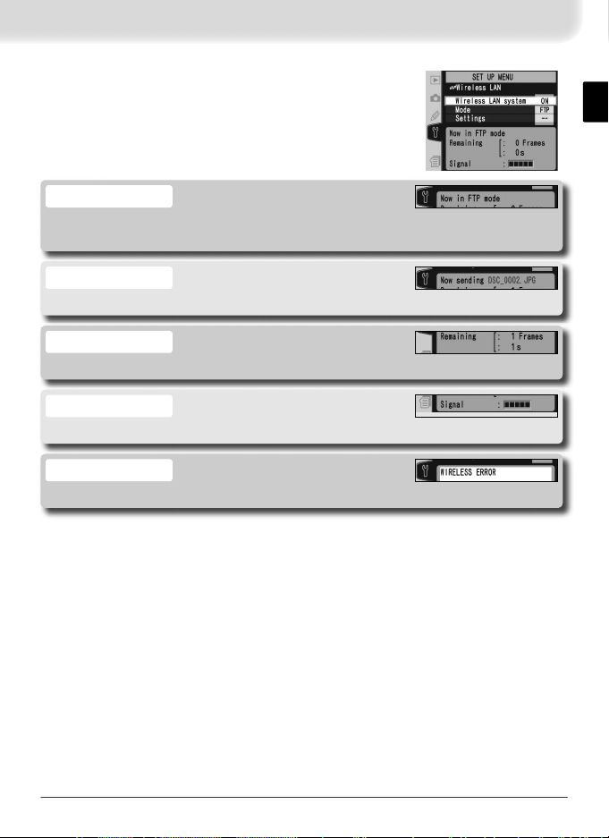
The Status Display
Network status can also be viewed in the top level of
the wireless LAN menu.
Status
The status of the connection between the server and the camera. “Now in FTP
mode” is displayed when the camera is connected.
Now sending
The name of the fi le currently being sent.
Remaining
The estimated time required to send the remaining images (frames).
Signal
A fi ve-level indicator of signal quality.
Error
Any errors that prevent the camera from connecting to the server.
13
Page 21
Controlling the Camera: PTP / IP Mode
In PTP / IP mode, a camera equipped with a WT-2 can be controlled over a wireless network from a computer running Nikon Capture 4 version 4.2 or later
(available separately) and photographs saved directly to the computer hard
disk. Before the camera can be controlled from the computer, wireless settings must be adjusted appropriately and the camera and computer must be
“paired” using special software. The principal steps involved in using PTP / IP
mode for the fi rst time are as follows:
1—Installing Pairing Software ................................ 39
2—Setup Using the Connection Wizard ............ 15–16
3—Pairing......................................................... 17–19
4—Connecting to the Computer ........................... 20
5—Controlling the Camera.................................... 21
Steps 1–3 can be omitted once the WT-2 has been set up for connection to a
particular computer.
Installing Pairing Software
The Wireless Connecting Utility supplied with the WT-2 must be installed on
the host computer before it can be paired with the camera. See page 39 for
more information.
Wireless Network Settings
For information on adjusting wireless network settings without using the Connection
Wizard, see “Menu Guide” ( 26–31). See page 25 for information on loading settings fi les created with a computer.
Firewalls
PTP / IP mode uses UDP port 5353. It may be necessary to adjust fi rewall settings before
connecting to a computer behind a fi rewall.
14
Page 22
Setup Using the Connection Wizard
쐃쐃쐇쐇쐋
First-time setup can be completed with the help of the Connection Wizard.
Make sure the network is active before starting. To prevent changes to settings from being lost should the camera monitor turn off automatically, use
the optional AC adapter or choose the maximum camera monitor off delay.
Tu rn the camera on.
1
Check that Off is selected for Wireless LAN >
2
Wireless LAN system in the camera setup menu
( 24).
Select PTP / IP for Wireless LAN > Mode ( 24).
3
In the top level of the wireless LAN menu, press the button to start
4
the Connection Wizard. A list of available connections will be displayed.
Press the multi selector up or down to highlight the desired connection
and press the multi selector to the right to select it.
icon.
쐃 Selected connection is marked with
쐇 Infrastructure connections are marked with icon,
ad-hoc connections with icon ( 27).
쐋 SS-ID (not displayed if SS-ID is unavailable).
쐋
Connection Not Available
If the desired connection is not listed, press the button to search again. If the
connection still can not be found, check settings on the network.
15
Page 23
Press the button.
5
SS-ID
If prompted for an SS-ID, press the multi selector to the
right and enter the connection SS-ID as described on
page 26.
Encryption Key
If prompted for an encryption key, press the multi selector to the right and enter a key as described on page
27.
If the network is confi gured to supply an IP ad-
6
dress automatically by DHCP server or Auto IP (
51), press the multi selector to the right to select
Obtain automatically. If the network requires a
fi xed IP address or subnet mask, enter the information supplied by the network administrator (
28). Press the button to proceed to Step 7.
The dialog shown at right is displayed when setup
7
is complete. Press the button to exit the wizard
and return to the wireless LAN menu.
Errors
If an error is displayed, press the multi selector to the left and enter a valid setting. A
“WIRELESS ERROR” or “TCP / IP ERROR” indicates that the associated options are set
incorrectly. After checking settings for the host or access point, press the button to
restart the Connection Wizard and adjust camera settings to match.
Related Settings
To access advanced settings when entering data in steps 5–6, press the button. The
related section of the network settings menu will be displayed ( 26–31).
16
Page 24
Pairing
Once wireless network settings have been adjusted, the camera and computer must be “paired” before they can communicate in PTP / IP mode for the
fi rst time. “Pairing” allows the computer to control the camera by establishing permissions between the two devices.
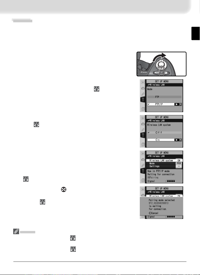
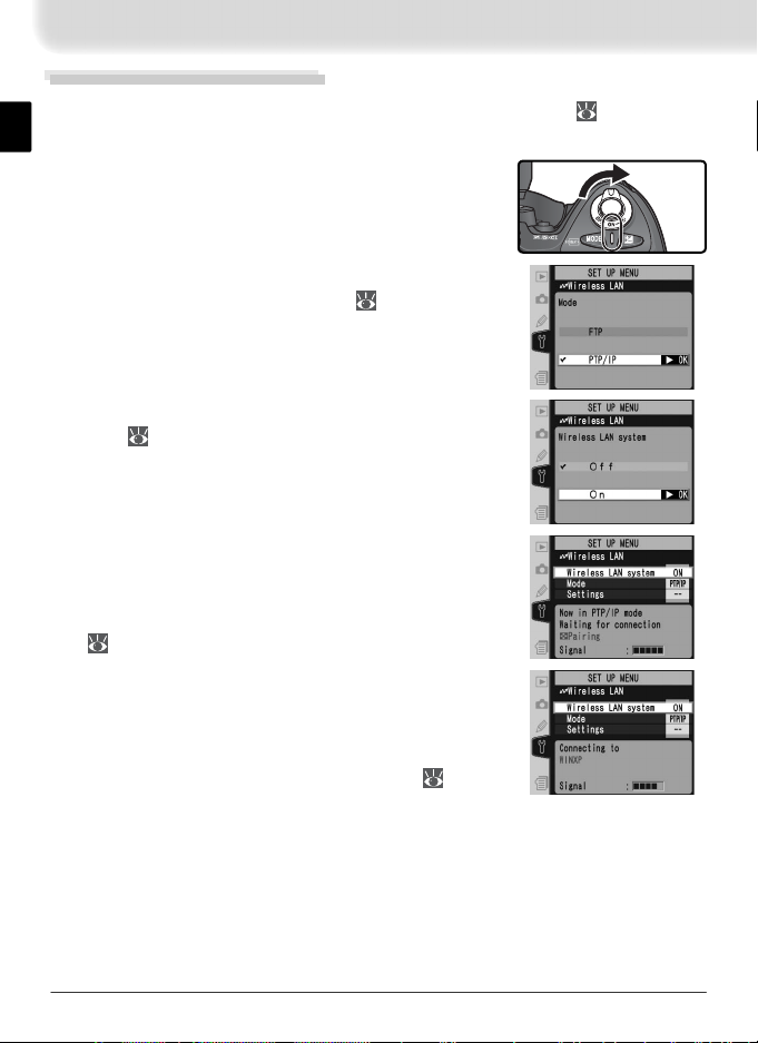
Tu rn the camera on.
1
Select PTP / IP for the Wireless LAN > Mode op-
2
tion in the camera setup menu ( 24).
Select On for Wireless LAN > Wireless LAN sys-
3
tem ( 24).
Confi rm that “Now in PTP / IP mode / Waiting for
4
connection” is displayed in the top level of the
wireless LAN menu. For information on what to
do if an error is displayed, see “Troubleshooting”
( 50).
Press the camera button. The message shown
5
at right will be displayed, with the camera name
in blue ( 36).
Pairing
The camera connection list ( 36) can store the names of up to ten computers (note
that attempting to control the camera simultaneously from multiple computers may
produce unexpected results; 21). When the connection list is full, computers can be
deleted from the list to make room for additional pairings.
17
Page 25
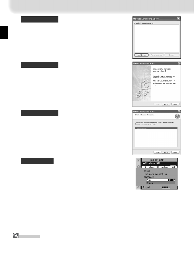
On the computer: Tu rn on the computer and start
6
the Wireless Connecting Utility. Click Add device.
On the computer: Click Next.
7
On the computer: A list of available cameras will
8
be displayed. Select the desired camera and click
Next.
On the camera:
the camera monitor stating that the computer
9
is requesting a connection. Highlight Yes and
press the multi selector to the right. The message “Connected to (computer name)” will be
displayed when pairing is complete.
Mac OS X
Although the illustrations on these pages are taken from Windows XP, the pairing process for Mac OS X is identical to that described here.
18
A message will be displayed in
Page 26
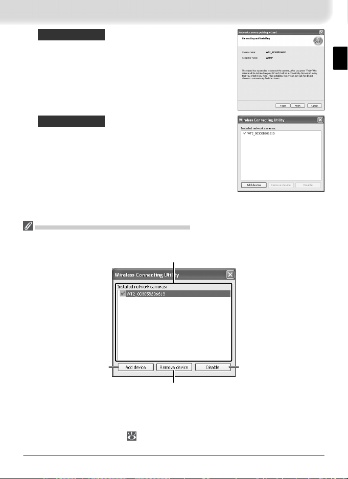
On the computer: Click Finish. If instructed to in-
10
stall a driver, follow the on-screen instructions to
complete installation. If a dialog appears prompting you to select a program to perform an action,
click Cancel.
On the computer: A check mark will appear next
11
to the camera name in the Wireless Connecting
Utility window. Pairing is now complete; close the
Wireless Connecting Utility.
The Wireless Connecting Utility Window
Installed network cameras: A list of
the cameras with which the computer can pair.
Add device: Add a
camera to the list of
installed network cameras.
Remove device: Remove the selected device from the list of installed
network cameras. To reconnect
with this device, delete the computer from the camera connection
list (
36) and repeat the pairing
process.
Disable / Enable: Disable
or enable the selected
pairing.
19
Page 27
Connecting to the Computer
Tu rn on a computer that has been paired with the camera ( 17) and wait
1
for it to start up.
Tu rn the camera on.
2
Select PTP / IP for the Wireless LAN > Mode op-
3
tion in the camera setup menu ( 24).
Select On for Wireless LAN > Wireless LAN sys-
4
tem ( 24).
Confi rm that “Now in PTP / IP mode / Waiting for
5
connection” is displayed in the top level of the
wireless LAN menu. For information on what to
do if an error is displayed, see “Troubleshooting”
( 50).
The connection is complete when the message,
6
“Connected to (computer name),” is displayed in
the pairing options menu. If the camera continues
to display the “waiting for connection” message,
repeat the steps described in “Pairing” ( 17).
20
Page 28
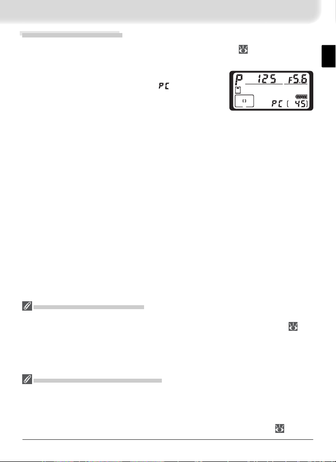
Controlling the Camera
Complete the steps in “Connecting to a Computer” ( 20).
1
Start Nikon Capture 4 Camera Control on the
2
host computer and confi rm that is displayed in
the camera’s top control panel.
Control the camera as described in the Nikon Cap ture 4 User’s Man u al.
3
Any photographs taken while the camera is connected will be recorded
directly to the computer hard disk.
Loss of Signal During Transfer
A loss of signal may interrupt the connection while pictures are being transferred to
Nikon Capture 4 Camera Control. If the POWER LED on the WT-2 is blinking ( 22),
select Off for the Wireless LAN > Wireless LAN system option in the camera setup
menu and then select On again. Transfer will resume when the connection is re-established. Do not turn the camera off. Transfer can not be resumed once the camera
is turned off.
Connecting to Multiple Computers
Any computer enabled in the connection list can connect to the camera when running
Nikon Capture 4 Camera Control. Note, however, that attempting to control the camera simultaneously from multiple computers may produce unexpected results. Nikon
recommends disabling the other connections if you are unsure whether the other computers in the connection list are running Nikon Capture 4 Camera Control ( 36).
21
Page 29
Network Status
POWER
L
IN
K
BUSY
POWER
L
IN
K
BUSY
The status of the link between the computer and the WT-2 is shown by the
status LEDs and by the display in the top level of the wireless LAN menu.
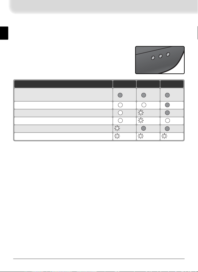
The Status LEDs
The POWER LED lights when the WT-2 is receiving
power from the camera.
Signal quality is shown by
the LINK LED: the faster the LED blinks, the better the
signal and the faster data can be transmitted. The
BUSY LED lights when a connection is established.
BUSYLINKPOWERStatus
Camera or exposure meters off, or Off selected
for Wireless LAN > Wireless LAN system
Connecting to computer
(on)
(off) (off) (off)
(on) (off)
(off) (blinks) (on)Waiting for connection; pairing possible
(on) (blinks) (on)Connected; camera control possible
(off) (off) (blinks)Connection error
(blinks) (blinks) (blinks)WT-2 hardware malfunction
22
Page 30
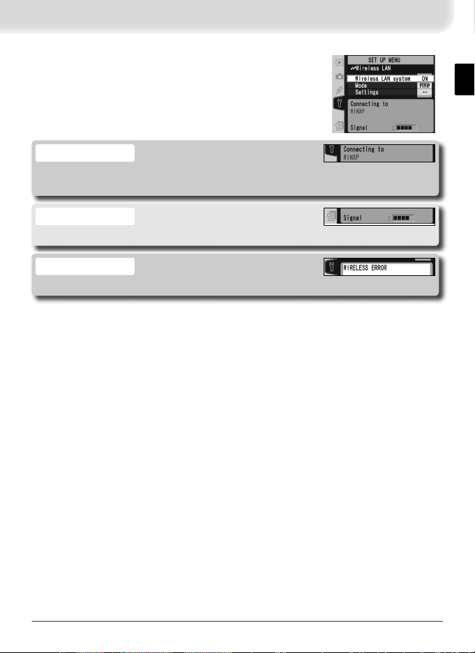
The Status Display
Network status can also be viewed in the top level of
the wireless LAN menu.
Status
The status of the connection between the computer and the camera. “Connected
to (computer name)” is displayed when the camera is connected.
Signal
A fi ve-level indicator of signal quality.
Error
Any errors that prevent the camera from connecting to the computer.
23
Page 31

Menu Guide
This section describes the settings available for the
Wireless LAN option in the camera setup menu
when the WT-2 is connected.
Wireless LAN system
Turn the WT-2 transceiver on or off.
Option Description
WT-2 receives no power from camera. Select
Off
(default)
Mode
Choose FTP for ftp mode ( 5), PTP / IP for PTP / IP
mode ( 14).
Settings
Adjust wireless network settings ( 25–35), ftp settings ( 37–38), or PTP / IP settings ( 36).
this option to reduce drain on batteries.
WT-2 on; wireless communication possible. If
ftp mode is selected, transmission of images
On
marked with “send” icon begins immediately.
24
Page 32

Network Settings
Adjust settings for connection to a wireless network
or ftp server (
26–35, or see page 42 for sample ftp
settings). These settings can also be made with the
help of the Connection Wizard ( 6, 14) or by loading a settings fi le that has been saved to the camera
memory card with a computer (
25). To prevent the
camera monitor from turning off while adjusting settings, set the Monitor
off Custom Setting to 10 m or use an optional EH-6 AC adapter to power
the camera.
Choose Settings
Camera network settings are saved in one of four
banks. Any changes to settings using the menus or
Connection Wizard will be saved in the current bank,
and are recalled when this bank is selected again.
Option Description
A–D Select bank.
Rename Rename selected bank.
Load Settings File
Load a network settings fi le that has been saved to
the camera memory card using a computer.
Option Description
No
(default)
Exit without changing settings.
Load Wireless, TCP/IP, and FTP settings from
Yes
memory card.
Creating a Settings File
An application for creating settings fi les is available from the websites listed on page 1
of this manual. After creating a settings fi le, save it to the root directory of the memory
card using a CompactFlash card reader or PCMCIA memory card adapter. No more
than one settings fi le should be stored on the memory card at a time. Additional information is available from the download site.
25
Page 33

Wireless
and right buttons on multi
s
.
Adjust settings for connection to a wireless network.
The wireless menu has two pages of options; to scroll
between pages, press the multi selector up or down.
Wireless Menu, Page 1/2
SSID: A BSS- or ESS-ID is required for connection to a
wireless LAN adapter or access point. Leave this fi eld
blank to allow the network to set the SS-ID automatically (“any” connection). To change the BSS- or ESSID, highlight the current ID, press the multi selector to
the right, and enter a new ID as described in the note
below. Press to return to the wireless menu (1/2).
Text Entry in the “Settings” Menu
If text entry is required to complete the selected setting, the following dialog will be
displayed.
Keyboard area
Use multi selector to highlight letters, press center
to select.
Use the multi selector to highlight the desired character in the keyboard area and press
the center of the multi selector to insert the highlighted character at the current cursor
position. To delete the character under the cursor, press the button. To move the
cursor to a new position, press the button while using the multi selector. No more
than thirty-two characters can be entered; if additional characters are entered when the
display is full, all characters after the thirty-third will be deleted.
To complete entry and return to the previous menu, press the button. To exit to the
setup menu without completing text entry, press .
Text display area
Text appears in this area.
To move cursor, press
while using up, down, left,
elector
26
Page 34

Communication mode: Choose a mode according to
how the wireless network is set up.
Option Description
Infrastructure
(default)
Ad-hoc
*
Channel
Connection to wireless network is via access point.
Direct peer-to-peer wireless connection
to host using IEEE 802.11b standard (IEEE
802.11g is not available in this mode).
1
Choose channel.
* Not required if Infrastructure is selected for Communication mode.
† The WT-2 offers a choice of thirteen channels (1–13), the WT-2A a choice of eleven
channels (1–11).
Wireless Menu, Page 2/2
Encryption
†
1
Highlight encryption method.
2
Return to wireless menu (1/2).
2
Return to wireless menu (2/2).
Highlight encryption key.
3
27
Page 35

Edit encryption key:
4
• Base 16: press multi selector left or
right to select character, up or down
to change. 64-bit keys are 10 digits
long, 128-bit keys 26 digits long.
• ASCII / TKIP: enter key as described on
page 26. 64-bit keys are 5 characters
long, 128-bit keys 13 characters long,
TKIP keys 8 to 64 characters long.
Return to wireless menu (2/2).
5
TCP / IP
Adjust TCP / IP settings as described on the following
pages. The TCP / IP menu has three pages of options;
to scroll between pages, press the multi selector up
or down.
TCP / IP Menu, Page 1/3
Obtain automatically: Highlight this option and press
the multi selector right to toggle it on (✔) or off. Turn
this option on if the wireless network is confi gured to
supply an IP address automatically by DHCP server or
Auto IP ( 51). Otherwise turn it off and enter the
address and subnet mask supplied by the network
administrator as described on the following page.
28
Page 36

1
2
Highlight Address.
3
Press multi selector left or right to se-
lect, up or down to change.
5
Highlight Mask.
7
Choose subnet mask.
Enter edit mode.
4
Exit to TCP / IP menu (1/3). If subnet
mask is required, proceed to Step 5.
6
Enter edit mode.
8
Exit to TCP / IP menu (1/3).
29
Page 37

TCP / IP Menu, Page 2/3
Use gateway: Highlight this option and press the multi
selector right to toggle it on (✔) or off. If the network
requires a gateway address, turn this option on and
enter the address supplied by the network administrator as described below.
1
Highlight Address.
3
Press multi selector left or right to se-
lect, up or down to change.
2
Enter edit mode.
4
Return to TCP / IP menu (2/3).
30
Page 38

Enable DNS: Highlight this option and press the multi
selector right to toggle it on (✔) or off. If a Domain
Name Server (DNS) exists on the network, turn this
option on and enter the address supplied by the network administrator as described below.
1
Highlight Address.
3
Press multi selector left or right to se-
lect, up or down to change.
TCP / IP Menu, Page 3/3
MAC address: This fi eld lists the twelve-digit Media
Access Control (MAC) address for the WT-2.
2
Enter edit mode.
4
Return to TCP / IP menu (2/3).
31
Page 39

FTP (FTP Mode Only)
Adjust ftp settings as described on the following pages. The ftp menu has four pages of options; to scroll
between pages, press the multi selector up or down.
FTP Menu, Page 1/4
Server
1
Highlight Address.
3
4
Highlight Port.
6
Press multi selector left or right to se-
lect, up or down to change.
2
Display text entry dialog ( 26).
Enter URL or IP address of ftp server (if unsure of correct address, contact server administrator). Press button to return to
ftp menu (1/4). If port number is required,
proceed to Step 4.
5
Enter edit mode.
7
Return to ftp menu (1/4).
32
Page 40

PASV mode: Highlight this option and press the multi
selector right to toggle PASV mode on (✔) or off.
Turn this option off to use normal (PORT) mode. Be
sure the server supports PASV mode before turning
this option on.
FTP Menu, Page 2/4
Anonymous login: Highlight this option and press the
multi selector right to toggle it on (✔) or off. Turn this
option on for anonymous login, off to enter a user
name and password as described below.
1
Highlight User ID.
Enter user name for login to ftp server and press button to return to ftp
menu (2/4).
3
4
Highlight Password.
6
2
Display text entry dialog ( 26).
5
Display text entry dialog ( 26).
After entering password for login to ftp
server, press button to return to ftp
menu (2/4). Password is disguised as row
of dots.
33
Page 41

FTP Menu, Page 3/4
Use home folder: Highlight this option and press the
multi selector right to toggle it on (✔) or off. Turn
this option on to upload fi les to the server’s default
“home” folder, off to specify a directory as described
below.
1
Highlight Folder.
3
Home Folder
On a Windows ftp server, the home folder is the same as the home directory ( 45).
On a Macintosh, the home folder is the root directory of the user folder for the current
account.
2
Display text entry dialog ( 26).
After entering name of destination folder
on ftp server, press button to return to
ftp menu (3/4).
34
Page 42

FTP Menu, Page 4/4
Use proxy server: Highlight this option and press the
multi selector right to toggle it on (✔) or off. If a
proxy server is required for ftp, turn this option on
and enter an address and port number as described
below.
1
Highlight Address.
Enter proxy server address and press button to return to ftp menu (4/4).
2
Display text entry dialog ( 26).
3
4
Highlight Port.
6
Press multi selector left or right to se-
lect, up or down to change.
5
Enter edit mode.
7
Return to ftp menu (4/4).
35
Page 43

Pairing Options (PTP / IP Mode Only)
This menu offers the following pairing options (for more information on pairing, see page 17):
Camera
The name under which the camera is registered when
paired with a computer. The default name is “WT2_”
followed by the MAC address of the WT-2. To use
a different name, highlight the current name in the
pairing options menu, press the multi selector to the
right, and edit the name as described on page 26.
The maximum length is thirty-nine characters.
Edit Connection List
Selecting this option displays the computers with
which the camera is paired. To enable or disable a
pairing with a selected computer or delete computers
from the list, highlight the computer name and press
the multi selector to the right. The menu shown at
right will be displayed.
Option Description
Enable Enable pairing with selected computer.
Disable Disable pairing with selected computer.
Select Yes to delete selected computer from connection list. Camera
Delete
can not be used with computer in PTP / IP mode until camera has been
removed from list of installed network cameras in Wireless Connecting
Utility ( 19) and pairing performed again.
36
Page 44

Auto Send (FTP Mode Only)
Choose whether to upload photographs to the server
as they are taken.
Option Description
Photos are not automatically uploaded to server
Off
(default)
* Pictures will not be uploaded to the server if Off is selected in the Wireless
LAN > Wireless LAN system menu. Pictures will instead be marked with a “send”
indicator as they are recorded to the memory card.
as they are taken. Photos can be selected for
transmission when camera is in playback mode.
Photos are uploaded immediately after being recorded to camera memory card. * Be sure mem-
On
ory card is inserted in camera before shooting.
Delete After Send (FTP Mode Only)
Select On to delete photographs from the camera
memory card automatically after they have been successfully uploaded to the server (the default option is
Off). Files that were uploaded before this option was
selected are not affected. Photographs will not be
deleted while displayed in slide shows or in the delete,
print set, and preset white balance menus. Sequential fi le numbering is used
while this option is in effect, regardless of the option selected for the File No.
Seq. Custom Setting.
37
Page 45

Send File As (FTP Mode Only)
When uploading NEF + JPEG images to an ftp server,
choose whether to send both NEF (RAW) and JPEG
fi les or only the JPEG fi les.
Option Description
NEF (Raw) + JPEG
(default)
JPEG only Upload JPEG fi les only.
Upload both NEF (RAW) and JPEG
fi les. JPEG fi les are sent fi rst.
Send Folder (FTP Mode Only)
All fi les in the selected folder (including those already
marked as “sent”) will be uploaded in ascending
order by fi le number, beginning when the folder is
selected. The folder itself will not be uploaded. This
option is not available when the memory card contains no folders.
Deselect All (FTP Mode Only)
Select Yes to remove “send,” “sending,” and “sent”
marking from all images on the memory card. Upload
of any images marked with a “sending” icon will immediately be terminated.
38
Page 46

Appendices
Installing Pairing Software
This section describes how to install the pairing software supplied with the
WT-2 ( 17). This software is required when using the WT-2 in PTP / IP mode
( 14).
Supported Operating Systems
This software requires Mac OS X version 10.3 or later or preinstalled versions of Windows XP Professional or Windows XP Home Edition.
Installation (Windows XP)
Start the computer and log in to an account with administrator privi-
1
leges.
Insert the supplied installer CD in a CD-ROM drive.
2
The “Select Region” dialog will be displayed; select a region and click Next.
If the “Select Region” Dialog Is Not Displayed
If the “Select Region” dialog is not displayed, select My Computer from the Start
menu and double-click the icon for the CD-ROM drive containing the installer CD.
Select a language and click Next.
3
Click Easy Install.
4
Click Next.
5
39
Page 47

A license agreement will be displayed. After read-
6
ing the agreement, select I accept the terms in
the license agreement and click Next to accept
and proceed with installation.
The default install location is displayed. Click
7
Next to install the software to this folder. To
choose another folder, click Change… and navigate to the desired location.
Clicking Next in Step 7 displays the dialog shown
8
at right. Click Install.
Click Finish.
9
Click Yes to restart the computer.
10
40
Page 48

Installation (Mac OS X)
Start the computer and log in to an account with administrator privi-
1
leges.
Insert the supplied installer CD in a CD-ROM drive. Double-click the
2
installer CD icon on the desktop, and then double-click the Welcome
icon.
The “Select Region” dialog will be displayed. Se-
3
lect a region and click Next.
Select a language and click Next.
4
Click Install.
5
Enter the administrator name and password and
6
click OK.
A license agreement will be displayed. After
7
reading the agreement, click Accept to accept its
terms and proceed with installation.
41
Page 49

Click Install.
8
Click Yes to add the Wireless Connecting Utility to
9
the Dock, No to proceed without adding it to the
Dock.
Click Quit.
10
Click Restart to restart the computer.
11
Sample ftp Settings
The following pages describe how to set up a simple infrastructure network
using the WT-2 and a Windows XP Professional ftp server. Encryption and
network security are not discussed.
1—Preparation....................................................... 42
2—Building a Network........................................... 43
3—Confi guring the Server ................................ 43–45
4—Confi guring the Wireless LAN Adapter ............. 45
5—Confi guring the WT-2.................................. 46–47
6—Uploading Pictures....................................... 48–49
Preparation
Ready the following items:
• D2X digital camera • WT-2 wireless transmitter
• ftp server 1 • wireless LAN adapter
1
Windows XP Professional computer with Internet Information Services (IIS) installed.
2
Bridge type. Additional settings may be required when using wireless router. See
documentation provided by manufacturer for details.
42
2
Page 50

Building a Network
Confi gure the network as shown below. In this example, the wireless LAN
access point is connected by a cable to the server, and the server is not connected to any other network devices.
C
L
C
S
A
/
V
O
U
T
DC
I
N
WT-2
BUSY
BUSY
K
K
IN
IN
L
L
POWER
POWER
K
C
O
L
Wireless LAN
access point
LAN cable
FTP server
Confi guring the Server
The following example assumes that Windows XP Professional and Internet
Information Services (IIS) are already installed (IIS is included in the standard
install of Windows XP Professional; for more information, contact Microsoft).
Be sure to use characters supported by the WT-2 ( 26) when specifying such
settings as user ID, password, and folder names.
Entering an IP Address
Open the Network and Internet Settings > Network Connections control panel. Right-click the
Local Area Connection icon and select Properties
from the menu that appears.
Select Internet Protocol (TCP/IP) and click Properties to display the “Internet Protocol (TCP/IP)” dialog. Enter an IP address and subnet mask for the
ftp server.
In this example, it is assumed that network uses class C private IP addresses
and subnet masks. Be sure IP address
differs from addresses assigned to wireless LAN adapter and WT-2. For example,
if ftp server is assigned 192.168.1.3,
192.168.1.1 can be assigned to adapter
and 192.168.1.2 to WT-2. All addresses
must be in same class.
43
Page 51

Creating an FTP Site
Go to the Performance and Maintenance > Administrative Tools control panel and open the
Internet Information Services console. Right-click
the Default FTP site folder and choose Properties
from the menu that appears. In the “Default FTP Site
Properties” dialog, open “FTP Site” and enter a TCP
Port number. The port number is normally 21.
Open “Security Accounts” and select Allow Anonymous Connections and
Allow IIS to control password. Make sure the default user ID (composed
of “IUSR” plus the computer name) is unchanged and leave the password
fi eld blank.
44
Page 52

Next, open “Home Directory” and select A directory located on this computer. The root directory for images uploaded to the ftp server is listed in
the Local Path text box; choose a folder and check Read, Write, and Log
visits.
Before proceeding to the next step, click OK to close the properties dialog.
Confi guring the Wireless LAN Adapter
The minimum information needed to confi gure a wireless LAN adapter is
listed below. Contact the manufacturer for details.
Wireless mode 802.11b or 802.11g
SS-ID 1D2X
Encryption (WEP) Off
“Any” connection 2Disabled
Channel Any
IP address 3Obtain IP address automatically: Off
Default gateway 000.000.000.000
MAC address 4Unspecifi ed
1
Same SS-ID must be assigned to WT-2.
2
Not required if adapter does not support “any” connection.
3
In this example, it is assumed that network uses class C private IP addresses and sub-
net masks. Address assigned to adapter must differ from addresses of server and WT-
2. For example, if ftp server is 192.168.1.3, 192.168.1.1 can be assigned to adapter
and 192.168.1.2 to WT-2. All addresses must be in same class.
4
If MAC address is required, enter MAC address for WT-2 ( 31).
IP address: 192.168.1.1
Subnet mask: 255.255.255.000
DNS 000.000.000.000
45
Page 53

Confi guring the WT-2
Before adjusting network settings as shown below,
select Off in the Wireless LAN > Wireless LAN sys-
tem menu.
Wireless
SSID 1D2X
Communication mode Infrastructure
Channel —
Encryption None
1
Same SS-ID must be assigned to wireless LAN adapter.
46
Page 54

TCP/IP
IP address 1Obtain automatically: Off
Gateway Use gateway: Off
1
In this example, it is assumed that network uses class C private IP addresses and
subnet masks. Address assigned to WT-2 must differ from addresses of server and
wireless LAN adapter. For example, if ftp server is 192.168.1.3, 192.168.1.1 can be
assigned to adapter and 192.168.1.2 to WT-2. All addresses must be in same class.
Address: 192.168.1.2
Mask: 255.255.255.000
DNS Enable DNS: Off
FTP
Server Address: 192.168.1.3
Port: 21
PASV mode Off
Anonymous login On
User ID
Password
Home folder 2On
Folder
Use proxy server Off
1
Enter address assigned ftp server ( 44).
2
Photographs are uploaded to folder selected in “Home Directory” tab of “Default FTP
Site Properties” dialog ( 45).
1
47
Page 55

Uploading Pictures
This section describes how to upload pictures as they are taken. For best results, the WT-2 and wireless LAN adapter should be within a few meters with
no obstacles between them.
Set the Wireless LAN > Mode option in the cam-
1
era setup menu to FTP and select On for Wire-
less LAN > Wireless LAN system.
Confi rm that a connection has been established.
2
To check the connection from the camera, confi rm
that “Now in FTP mode” is displayed in the top
level of the wireless LAN menu. For information
on what to do if the camera shows “WIRELESS
ERROR,” “TCP / IP ERROR,“ or “FTP ERROR,” see
“Troubleshooting” ( 50).
To check the status of the connection from the computer, right-click the
Default FTP site folder and select Properties from the menu that appears. Open “FTP Site” and click Current Sessions….
48
Page 56

Confi rm that “Anonymous” is listed under “Connected Users.” For information on what to do if no connection is listed, see “Troubleshooting”
50).
(
Select On for Wireless LAN > Auto send. Take a
3
picture and confi rm that the image has been uploaded to the specifi ed folder on the ftp server.
49
Page 57

Troubleshooting
Problem Solution
• Turn camera on.
• Press shutter-release button halfway to acti-
“POWER” LED does not light.
All LEDs blink at once.
Wireless LAN option not available in camera setup menu.
Excessive radio interference. Change orientation of camera or antenna. —
Camera displays wireless, TCP /
IP, or FTP error.
Can not connect to ftp server.
Transfer interrupted before all
photographs are sent.
vate exposure meters.
• Select On for Wireless LAN > Wireless
LAN system option in camera setup menu.
• Reattach WT-2.
WT-2 hardware error. Contact a Nikon-authorized service representative.
Select PTP for USB option in camera setup
menu.
Check settings for host and / or wireless LAN
adapter and adjust camera settings appropriately.
Check settings for server and / or wireless LAN
adapter and adjust camera settings as described
in “Sample ftp Settings.”
Transfer will resume if camera is turned off and
then on again, exposure meters are reactivated,
or On for Wireless LAN > Wireless LAN sys-
tem option in camera setup menu.
5
—
24
4
—
5
26
28
32
42
11
50
Page 58

Glossary
Ad-hoc
Devices in an ad-hoc wireless network communicate directly (“peer to peer”), without
a wireless access point. The WT-2 supports an ad-hoc mode for direct wireless connection to a computer or ftp server.
“Any” connection
Allows devices to connect to wireless network without an SS-ID. Can be used for wireless “hot spots” but is not as secure as connections that require an SS-ID.
Auto IP (APIPA—Automatic Private IP Addressing)
Allows devices in a network to automatically assign themselves unique IP addresses if
no DHCP server is found on the network. Auto IP uses addresses from 169.254.1.0
to 169.254.254.255 and a subnet mask of 255.255.0.0. These addresses are neither
global nor private but are reserved for Auto IP.
BSS-ID (Basic Service Set ID)
All wireless devices on an ad-hoc wireless network share the same BSS-ID. The BSS-ID
may be up to thirty-two characters long and is case sensitive. See also Ad-hoc.
Channel
When multiple wireless LANs with different ESS-IDs are operating on a single frequency
within a given area, transmission speeds will drop. Specifying a separate channel (frequency) for each network can prevent interference and increase transmission speeds
(note that all devices in the same network must be set to the same channel). In the
IEEE 802.11b/g standard, the 2.4 GHz band is divided into 14 channels, each separated
by 4 MHz.
DHCP (Dynamic Host Confi guration Protocol) Server
Each device in a TCP/IP network requires an IP address. If a DHCP server is present on
the network, IP addresses will be assigned automatically. A DHCP server will not be
present on networks that consist solely of Windows Me, Windows 98, or Windows 95
computers. DHCP may be enabled on other networks; consult the network administrator or see the manual provided with the router or operating system.
DNS (Domain Name Server)
A server that contains a database of IP addresses and host names for the machines it
administers and that converts host names to IP addresses in response to queries from
clients. Each DNS can also query other Domain Name Servers for addresses not listed
in its database.
ESS-ID (Extended Service Set ID)
Multiple BSSs can be confi gured to form an ESS, allowing users to roam between
wireless access points. Only devices with the same ESS-ID as a given access point can
communicate with that access point. The ESS-ID may be up to thirty-two characters
long and is case sensitive.
51
Page 59

Gateway
A network node that acts as an entrance to another network, for example between a
company network and the Internet.
IIS (Internet Information Services)
Microsoft’s name for its Web server software. Notable for its close connection to Windows-based systems through Active Server Pages (ASPs). When installed as part of the
operating system, IIS makes it relatively easy to build web a server.
Infrastructure
Devices in an infrastructure network communicate via one or more wireless access
points. The WT-2 supports an infrastructure mode for connection to a wireless network
via an access point.
IP address
Address given to each node in a TCP/IP network. All nodes in a TCP/IP network must
have a unique IP address. Private IP addresses are recommended for nodes that are part
of a local network.
LAN (Local Area Network)
A network of computers located in relatively close proximity to one another. LANs
generally support data transfer speeds of 10–100 Mbps.
MAC (Media Access Control) Address
A unique hardware address for each device on a network, required when sending and
receiving packets.
PASV mode
PASV mode is used by clients behind fi rewalls, when it allows the ftp server to supply
the port number.
Private IP address
An IP address that is only visible within a local network. Because packets using a
private IP address can not be transmitted to another network, they are usually sent
between networks via a proxy server or NAT. Private IP addresses in the range 10.0.0.0–
10.255.255.255 are termed “class A.” Class B addresses are in the range 172.16.0.0–
172.31.255.255, class C addresses in the range 192.168.0.0–192.168.255.255. The
class of address used depends on the size of the network. Class C addresses are often
used for small networks.
Protocol
A set of rules for passing information back and forth between devices in a network. By
defi ning such elements of communication as how links are established, how receipt of
a signal is acknowledged, how data are encoded, and how to handle errors, a protocol
ensures that data are transmitted without loss of information.
52
Page 60

Proxy
A server that stands between large networks and local networks or computers, typically
to ensure security. One element of a fi rewall.
PTP / IP (Picture Transfer Protocol over Internet Protocol)
An image transfer for transmitting images over wireless LANs. It represents an extension to the Picture Transfer Protocol (PTP) used to transfer images between cameras and
computers connected via USB cable.
SS-ID (Service Set ID)
An SS-ID prevents interference between devices in different networks. See BSS-ID,
ESS-ID.
Subnet mask
A mask that divides a network into subnets.
TCP/IP (Transmission Control Protocol/Internet Protocol)
A dual protocol consisting of a transport-layer protocol (TCP) that divides data into
packets which it later reassembles, and a network protocol (IP) that handles transmission of the packets between points in the network. It can be implemented on different
platforms, allowing data to be transmitted between machines with different operating
systems.
TKIP (Temporal Key Integrity Protocol)
An encryption method which uses dynamic keys that change periodically or after a
specifi ed amount of data have been transmitted, making it more secure that WEP,
which uses fi xed keys.
UDP (User Datagram Protocol)
A fast but unreliable transport layer transmission protocol using the DSI model.
USB (Universal Serial Bus)
A standard for connecting peripheral devices. USB supports data transfer rates of up to
480 Mbps (USB 2.0). Devices connected via USB can be connected and disconnected
with the power on (“hot plug”) and do not require separate IRQ (interrupt request)
numbers, preventing confl icts with other devices.
WEP (Wired Equivalent Privacy)
A privacy protocol intended to provided users of wireless networks with the same level
of privacy as a wired network. When using WEP, enter the encryption key provided by
the network administrator.
Wireless LAN access point
A wireless transceiver that acts as the connection between wireless devices and a wireless network.
53
Page 61

Specifi cations
Standards
IEEE 802.11b/g
(standard for low power data communications systems)
Communication
protocols
(line of sight)
IEEE 802.11g: OFDM
IEEE 802.11b: DBPSK, DQPSK, CCK
Approximately 30 m (98´) with WA-S1 standard antenna
Range
Approximately 150 m (492´) with WA-E1 extended range antenna
and large antenna at wireless LAN access point
Operating
frequency
Data rates
WT-2: 2412–2472
WT-2A: 2412–2462
*
IEEE 802.11g: 6, 9, 12, 18, 24, 36, 48, and 54
IEEE 802.11b: 1, 2, 5.5, and 11 Mbps
TKIP, 128/64-bit (104/40-bit) WEPSecurity
Infrastructure / ad-hocAccess protocols
Current
consumption
consumption
Operating
environment
Sleep: 200 mA maximum (at input voltage of 13.5 V)
Send: 250 mA maximum (at input voltage of 13.5 V)
Power
3.4 W maximum
Temperature: 0–40 °C (32–131 °F)
Humidity: less than 85% (no condensation)
210 g / 7.4 oz (excluding antenna)Weight
Dimensions
(W × H × D)
146.5 mm × 34.5 mm × 65.5 mm (5.8˝ × 1.4˝ × 2.6˝)
* Maximum logical data rates according to IEEE standard. Actual rates may differ.
(standard wireless LAN protocol)
MHz (13 channels)
MHz (11 channels)
Mbps
, ARIB STD-T66
54
Page 62

Index
Symbols
, 11
A
Access point. See Wireless
LAN, access point
Ad-hoc, 27
Antenna, 3
Auto send, 37
B
BSS-ID, 26, 51
BUSY. See Status LEDs
C
Channel, 27
Choose settings, 25
Connection list, 19, 36
Connection Wizard, the, 6, 14
Connecting the WT-2, 4
D
Delete after send?, 37
Deselect all?, 38
DHCP server, 8, 16, 28, 51
Domain Name Server (DNS),
31, 51
E
Encryption, 27
key, 7, 15, 27
Errors, 8, 16
ftp, 8, 50
TCP / IP, 8, 16, 50
wireless, 8, 16, 50
ESS-ID, 26, 51
F
File names, 10, 13
Folders, 8, 34. See also Send
folder
FTP, 24
ftp
errors. See Errors, ftp
mode, 2, 5
server, 2, 42
FTP ERROR. See Errors, ftp
G
Gateway, 30
I
IP address, 8, 16, 28, 52
Infrastructure, 27
L
LAN. See Wireless LAN
LED. See Status LEDs
LINK. See Status LEDs
Link quality, 13, 23
Load settings fi le?, 25
M
MAC address, 31
Memory cards, 9, 25, 37
Menus, 24–38
entering text in, 26
Mode, 24
N
Network settings, 25
Network settings fi les, 25
Nikon Capture 4, 2, 14, 21
P
Pairing, 14, 17, 39
Pairing options, 36
Password, 33
PASV mode, 33, 52
Port, 32
POWER. See Status LEDs
Proxy, 35, 53
PTP, 5
PTP / IP, 14, 53
mode, 2, 14
S
Send folder, 38
Send fi le as, 38
Server. See ftp, server
Settings, 24
Settings fi les. See Network
settings fi les; Load set-
tings fi le
SS-ID, 7, 15, 26
Status. See Link quality; Status
LEDs
Status LEDs, 3, 12, 22
T
TCP/IP, 28
TCP/IP, 8, 16, 28, 53
U
Upload, 10
deleting images after, 37
interrupting, 11
selecting images for, 10
USB, 5
User ID, 8, 33
V
Voice memos, 10
W
Wireless, 26
Wireless LAN, 5, 24
Wireless LAN, 5, 24
access point, 2, 45
confi guration, 45
Wireless LAN system, 6,
20, 24
55
Page 63

Page 64

Système de communication
W T-2
sans fi l
WT-2
C
L
C
S
A
/
V
O
U
T
D
C
IN
Y
Y
S
S
U
U
B
B
LINK
LINK
R
R
E
E
POW
LOCK
POW
Fr
Manuel de l'utilisateur
Page 65

Informations sur les marques commerciales
Macintosh et Mac OS sont des marques commerciales d’Apple Computer, Inc. Microsoft et Windows sont des marques
déposées de Microsoft Corporation. Tous les autres noms commerciaux mentionnés dans le présent manuel ou dans
toute autre documentation fournie avec ce produit Nikon sont des marques commerciales ou déposées de leurs
détenteurs respectifs.
Apple Public Source License
Ce produit inclut le source code mDNS Apple qui est soumis aux termes de la Licence de « Apple Public Source License »
qui se trouve sur le site Web http://developer.apple.com/darwin/.
Portions Copyright (c) 1999-2004 Apple Computer, Inc. Tous droits réservés.
Ce fi chier contient du Code d'Origine et/ou des Modifi cations du Code d'Origine tels qu'ils sont défi nis dans, et
sont assujettis à, la Licence de « Apple Public Source License Version 2.0 » (la « Licence »). Vous ne devez utiliser ce
fi chier que dans le cadre de cette Licence. Vous trouverez une copie de cette Licence sur le site en anglais à l'adresse
http://www.opensource.apple.com/apsl/ à lire avant d'utiliser ce fi chier.
Le Code d'Origine et le logiciel distribués dans le cadre de la Licence sont fournis « tels quels », SANS AUCUNE
GARANTIE D'AUCUNE SORTE, EXPRESSE OU TACITE, ET APPLE EXCLUT PAR LA PRÉSENTE TOUTE GARANTIE, Y
COMPRIS DE FAÇON NON LIMITATIVE, TOUTE GARANTIE DE QUALITÉ MARCHANDE, DE QUALITÉ SATISFAISANTE,
D'ADÉQUATION À UN USAGE PARTICULIER, DE JOUISSANCE PAISIBLE ET DE NON VIOLATION. Veuillez consulter la
Licence dans votre langue pour les droits et les limites faisant foi sous cette Licence.
Page 66

Pour votre sécurité
Pour ne pas risquer d’endommager votre matériel Nikon ou de vous blesser, vous ou d’autres
personnes, prenez soin de lire attentivement les recommandations suivantes avant d’utiliser
votre matériel. Gardez ensuite précieusement ces consignes de sécurité dans un endroit facilement accessible à tous ceux qui se serviront de cet appareil photo.
Les conséquences dues au non-respect de ces consignes sont symbolisées de la manière
suivante :
Cette icône signale les avertissements et consignes qui doivent être impérativement lus
avant d’utiliser votre matériel Nikon car ils concernent un possible danger physique.
AVERTISSEMENTS
Ne démontez pas votre matériel
Le non-respect de cet avertissement peut provoquer un incendie, un choc électrique ou toute autre blessure.
Si le produit devait s’ouvrir suite à une chute ou tout autre accident, déconnectez la source d’alimentation de
l’appareil photo et confi ez le produit immédiatement à un centre de service agréé Nikon pour le faire vérifi er.
En cas de dysfonctionnement de votre appareil photo, mettez-le immédiatement hors tension
Si vous remarquez de la fumée ou une odeur inhabituelle provenant de votre matériel, retirez l’accumulateur
de l’appareil photo immédiatement en prenant soin de ne pas vous brûler. Vouloir persévérer à utiliser son
matériel dans ce cas peut être dangereux. Une fois l’accumulateur retiré, confi ez votre matériel à un centre de
service agréé Nikon pour le faire vérifi er.
Gardez votre matériel au sec
Vous ne devez ni placer le matériel dans l’eau, ni l’exposez à la pluie. Le non-respect de cette précaution
d’emploi est susceptible de déclencher un incendie ou un choc électrique.
N’utilisez pas votre matériel en présence de gaz infl ammable
Le non-respect de cette précaution d’emploi est susceptible de déclencher un incendie ou un choc électrique.
Ne manipulez pas l’appareil avec les mains mouillées
Le non-respect de cette précaution peut provoquer un choc électrique.
Conservez hors de portée des enfants
Le non-respect de cette précaution peut provoquer des blessures.
Suivez les instructions du personnel des hôpitaux et des compagnies aériennes
Cet appareil émet des rayonnements de fréquence radio électrique qui peuvent provoquer des brouillages
dans le matériel médical ou l’équipement de navigation. N’utilisez pas cet appareil dans un hôpital ou à bord
d’un avion sans en demander la permission préalable au personnel de l’hôpital ou de la compagnie aérienne.
N’exposez pas l’appareil à des températures élevées
Ne laissez pas cet appareil dans un véhicule fermé en plein soleil ou dans un autre lieu sujet à des températures extrêmement élevées. Le non-respect de cette précaution peut provoquer un incendie ou endommager
le boîtier ou les éléments intérieurs.
Observez les précautions nécessaires lorsque vous utilisez la WA-E1
Lorsque vous utilisez l’antenne longue portée WA-E1 (disponible séparément), veillez à ne pas vous blesser les yeux
accidentellement avec l’extrémité de l’antenne. Cela pourrait entraîner la cécité ou autres défi ciences visuelles.
i
Page 67

Remarques
• Les manuels fournis avec ce produit ne
peuvent être reproduits, transmis, transcrits, stockés sur un serveur ou traduits
quelle que soit la langue, en tout ou en
partie, et quels qu’en soient les moyens,
sans accord écrit préalable de Nikon.
•
Nikon se réserve le droit de modifi er les
caractéristiques techniques du matériel et
des logiciels décrits dans ces manuels à tout
moment et sans notifi cation préalable.
• Nikon ne sera tenu responsable pour les
dommages résultant de l’utilisation de
ce produit.
• Bien que tout ait été mis en œuvre pour
que les informations contenues dans ces
manuels soient exactes et complètes,
nous vous serions reconnaissants de
bien vouloir signaler toute erreur ou tout
oubli au représentant Nikon de votre
pays (adresse fournie séparément).
Déclaration de Conformité
U.S.A. Federal Communications Commission (FCC)
Déclaration de Conformité
Cet appareil est conforme à la section 15 du règlement de la FCC. Le fonctionnement de cet
appareil est sujet aux deux conditions suivantes :(1) Cet appareil ne doit pas provoquer de
brouillages préjudiciables et (2) Cet appareil ne doit accepter aucun brouillage susceptible de
provoquer un fonctionnement indésirable.
Les produits contenant un transmetteur
radioélectrique sont signalés par un
WT-2A
numéro d’identifi cation FCC et doit aussi
comporter le logo de la FCC.
Déclaration de la FCC (Federal Communications Commission) pour la protection contre les parasites
Cet équipement a été testé et trouvé conforme aux limites défi nies pour les appareils numériques de classe B selon la partie 15 de la réglementation FCC. Ces limites assurent une
protection raisonnable contre les interférences dangereuses lorsque l’équipement est utilisé
en environnement résidentiel. Cet équipement génère, utilise et peut irradier des radiofréquences qui peuvent, en cas d’une installation et d’une utilisation contraire aux instructions,
provoquer des interférences néfastes aux communications radio. Cependant, il n’existe
aucune garantie qu’une interférence ne se produira pas dans une installation particulière. Si
ce matériel provoque effectivement des interférences préjudiciables à la réception radio ou
télévisée, ce que l’on peut déterminer en allumant et en éteignant le matériel, l’utilisateur
est vivement encouragé à essayer de corriger ces interférences en ayant recours à une ou
plusieurs des mesures suivantes:
• Réorientez ou repositionnez l’antenne de réception.
• Augmentez la distance séparant l’équipement du récepteur.
• Branchez l’appareil photo à une prise reliée à un circuit différent de celui où est connecté le récepteur.
• Consultez un revendeur ou un technicien radio/télévision spécialisé.
ii
Page 68

Avis de la FCC relatif à l'exposition aux rayonnements
Aucune preuve scientifi que disponible ne met en évidence de problème de santé associé
à l’utilisation d’appareils sans fi l à faible puissance. Cependant, il n’est pas prouvé que ces
appareils sans fi l à faible puissance sont absolument inoffensifs pour la santé. Lors de leur
utilisation, ils émettent de faibles niveaux de radiofréquences (RF) comprises dans la plage
des micro-ondes. Même si des niveaux élevés de RF peuvent avoir des effets sur la santé (en
réchauffant les tissus), l’exposition à de faibles niveaux de RF qui ne génèrent aucune chaleur
n’entraîne aucun effet négatif connu sur la santé. Les nombreuses études des expositions à de
faibles niveaux de RF n’ont permis de détecter aucun effet biologique. Certaines études ont
émis l’hypothèse que certains effets biologiques risquent de se produire, mais ces découvertes
n’ont pas été confi rmées par des recherches supplémentaires. Le système de communication
sans fi l WT-2A a été testé et déclaré conforme aux directives de la FCC (Federal Communications Commission) relatives aux expositions à l'énergie émise par les radiofréquences (RF). Le
Débit maximal d’Absorption Spécifi que (DAS) émis par le système de communication sans fi l
WT-2 a été mesuré : il est de 0,267 W/kg au niveau de la tête.
Cet appareil ne doit pas être utilisé ou positionné à proximité d’une autre antenne ou d’un
autre système de communication du même type.
ATTENTION
Modifi cations
Le FCC demande qu’il soit notifi é à l’utilisateur que tout changement ou modifi cation sur cet
appareil qui n’aurait pas été expressément approuvé par Nikon Corporation peut annuler tout
droit à l’utilisateur d’utiliser l’équipement.
Nikon Inc.,
1300 Walt Whitman Road, Melville, New York
11747-3064, U.S.A.
Tel.: 631-547-4200
A l'attention des utilisateurs ca na diens
ATTENTION
Cet appareil numérique de la classe B respecte toutes les exigences du Règlement sur
le matériel brouilleur du Canada.
CAUTION
This class B digital apparatus meets all requirements of the Canadian Interference
Causing Equipment Regulations.
iii
Page 69

Table des matières
Pour votre sécurité......................................i
Remarques ................................................ii
Déclaration de Conformité .......................ii
A l'attention des utilisateurs canadiens ...iii
Introduction.......................................... 1
Protocoles pris en charge ..........................2
ftp...........................................................2
PTP / IP .....................................................2
Eléments du WT-2......................................3
Confi guration ....................................... 4
Étape 1 - Connecter le WT-2 ......................4
Étape 2 - Sélectionner PTP.........................5
Transfert d’images : mode FTP ............. 5
Confi guration à l’aide
de l’Assistant connexion..........................6
Connexion au serveur................................9
Transfert d’images...................................10
Interruption de la transmission...............11
Icône
État du réseau .......................................12
Contrôle de l’appareil photo :
mode PTP/IP ..................................... 14
Installation du logiciel de pairagee..........14
Confi guration à l’aide
de l’Assistant connexion........................15
Pairage ....................................................17
Connexion à l’ordinateur.........................20
Contrôle de l'appareil photo....................21
État du réseau .......................................22
...........................................11
Guide des menus................................ 24
Système com. sans fi l ..............................24
Mode.......................................................24
Paramètres ..............................................24
Paramètres du réseau.............................25
Options de pairage
(mode PTP/IP uniquement)...................36
Envoi automatique
(mode FTP uniquement).......................37
Effacer après envoi ?
(mode FTP uniquement).......................37
Format de fi chier :
(mode FTP uniquement).......................38
Envoi dossier
(mode FTP uniquement).......................38
Désélectionner tout ?
(mode FTP uniquement).......................38
Annexes.............................................. 39
Installation du logiciel de pairage ...........39
Installation (Windows XP)......................39
Installation (Mac OS X) ..........................41
Exemples de paramètres FTP...................42
Préparation............................................42
Installation d’un réseau..........................43
Confi guration du serveur........................43
Confi guration de la carte
réseau sans fi l......................................45
Confi guration du WT-2 ...........................46
Transfert d’images .................................48
Dépannage..............................................50
Glossaire..................................................51
Caractéristiques techniques.....................54
Index ...........................................................
iv
Page 70

Introduction
Merci d’avoir acheté le système de communication sans fi l WT-2 ou WT-2A pour
appareils photo numériques Nikon compatibles. Le WT-2 est destiné uniquement à
une utilisation en Allemagne, en Autriche, en Belgique, au Danemark, en Espagne,
en Finlande, en France, en Grèce, en Italie, au Japon, aux Pays-Bas, au Portugal, au
Royaume-Uni, en Suède et en Suisse. Le WT-2A est conçu exclusivement pour être
utilisé au Canada et aux États-Unis d’Amérique. La principale différence entre le
WT-2 et le WT-2A est le nombre de canaux pris en charge (voir p. 54) ; sauf indication contraire, toutes les références au WT-2 s’appliquent également au WT-2A.
Ce manuel décrit la connexion du WT-2 et le contrôle de l’appareil photo à partir
d’un ordinateur exécutant Capture 4 version 4.2 ou ultérieure (vendu séparément)
ou la transmission d’images vers un serveur par l’intermédiaire d’un réseau LAN sans
fi l. Avant d’utiliser le WT-2, n’oubliez pas de lire les mises en garde des pages i– iii.
Les symboles et les usages suivants sont utilisés tout au long de ce manuel:
Cette icône signale les mesures de précaution
dont il faut avoir connaissance avant d’utiliser
WT-2 pour ne pas risquer de l’endommager.
Cette icône signale des remarques et des
informations devant être lues avant toute
utilisation.
Cette icône signale les astuces et autres
informations qui peuvent s’avérer utiles
lors de l’utilisation de WT-2.
Connaissance de base
Dans ce manuel, il est supposé que les lecteurs possèdent les connaissances fondamentales en matière de serveurs ftp et de réseaux locaux sans fi l (LAN). Pour de plus amples
informations sur l’installation, la confi guration et l’utilisation d’équipements pour un
réseau sans fi l, contactez le fabricant ou l’administrateur du réseau.
Formation permanente
Dans le cadre de l’engagement de Nikon pour la « Formation permanente » sur ses
produits au niveau technique et éducatif, des informations continuellement mises à jour
sont disponibles en ligne sur les sites suivants :
• Etats-Unis: http://www.nikonusa.com/
• Europe: http://www.europe-nikon.com/support
• Asie, Océanie, Moyen-Orient et Afrique: http://www.nikon-asia.com/
Vous trouverez sur ces sites des informations relatives aux derniers produits, des astuces,
des réponses aux questions les plus fréquemment posées (FAQ) ainsi que des conseils
d’ordre général sur l’imagerie et la photographie numériques. Pour tout renseignement
complémentaire, contactez le représentant Nikon de votre pays. Voir l’adresse URL cidessous pour obtenir les coordonnées de la fi liale de votre pays (voir « Contact ») :
http://nikonimaging.com/
Cette icône signale que des informations
complémentaires sont disponibles à une
autre page du manuel.
1
Page 71

Protocoles pris en charge
Le système de communication sans fi l WT-2 est une carte réseau sans fi l permettant de contrôler l’appareil photo à distance depuis un ordinateur exécutant Nikon
Capture 4 version 4.2 ou ultérieure (vendu séparément) ou de transférer des photos vers un serveur FTP par l’intermédiaire d’un réseau LAN sans fi l. Le WT-2 prend
en charge les protocoles suivants :
ftp ( 5)
Les nouvelles photos et celles qui sont enregistrées sur la carte mémoire de l’appareil photo
peuvent être transférées vers un serveur FTP par l’intermédiaire d’un réseau LAN sans fi l.
C
L
C
S
A
/
V
O
U
T
DC
I
N
BUSY
BUSY
K
K
IN
IN
L
L
POWER
POWER
K
C
O
L
WT-2
Point d’accès
sans fi l
*
Serveur FTP
* Mode Infrastructure uniquement ; non nécessaire en mode ad-hoc ( 27).
PTP / IP ( 14)
L’appareil photo peut être contrôlé depuis un ordinateur sur le même réseau et les
photos peuvent être directement enregistrées sur le disque dur de l’ordinateur à
l’aide de Nikon Capture 4 version 4.2 ou ultérieure (vendu séparément ; connexion
via un routeur non prise en charge).
C
L
C
S
A
/
V
O
U
T
DC
I
N
BUSY
BUSY
K
K
IN
IN
L
L
POWER
POWER
K
C
O
L
WT-2
Point d’accès
sans fi l
*
Ordinateur
* Mode Infrastructure uniquement ; non nécessaire en mode ad-hoc ( 27).
Un environnement avec réseau LAN sans fi l est nécessaire pour utiliser le WT-2. Un
serveur FTP est requis pour le protocole FTP. Le fonctionnement correct a été vérifi é
sur les systèmes suivants :
• ftp: Windows Server 2003, Windows 2000 Server, Windows XP Professionnel,
Windows 2000 Professionnel, Mac OS X Server, Mac OS X. Les connexions FTP sur
Internet et les serveurs FTP exécutant des logiciels tiers ne sont pas pris en charge.
• PTP / IP : Windows XP Professionnel, Windows XP Édition familiale, Mac OS X
(version 10.3 ou ultérieure).
Pour obtenir les dernières informations sur les systèmes d’exploitation pris en
charge, consultez le site Web Nikon de votre région (
1).
2
Page 72

Eléments du WT-2
Vis de
montage
Molette de
verrouillage
LOCK
Contact alimentation
BUSY
LINK
POWER
Boîtier
Témoins
DEL: POWER
(vert), LINK
(orange),
BUSY (vert)
Antenne standard
(WA-S1)
Port de
l’antenne
Filetage
Câble USB
Antenne longue
portée WA-E1 avec
de fi xation
pour pied
fi letage pour fi xa-
tion sur pied (dispo-
nible séparément)
Volet du logement pour
accumulateur BL-2
(destiné au logement
pour accumulateur de
l’appareil photo)
Fixation d’une antenne
Antenne standard (WA-S1) Antenne longue portée WA-E1
Réorientation de l’antenne
Avant de réorienter la WA-S1, dévissez-la du port de l’antenne. Si vous utilisez la WA-E1
(vendue séparément), veillez à ne pas plier ou écraser le câble.
3
Page 73

LO
CK
POWERPOW
ER
LO
C
K
POWERPOW
ER
LO
C
K
POW
ER
L
IN
K
B
U
S
Y
POW
ER
L
IN
K
B
U
S
Y
Confi guration
Étape 1 - Connecter le WT-2
Mettez l’appareil hors tension.
1
Retirez la protection du contact d’alimentation de
2
l’appareil.Vous pouvez ranger la protection dans
le boîtier situé sur le WT-2.
Placez l’appareil sur le WT-2 et faites tourner la
3
molette de verrouillage dans le sens indiqué afi n
de fi xer le WT-2 sur le fi letage de fi xation pour
pied de l’appareil.
Soulevez la protection du port USB de l’appareil
4
photo et connectez le câble USB au port USB.
Passez le câble derrière la glissière située sur le
5
volet du logement pour accumulateur BL-2.
Déconnexion du WT-2
Pour déconnecter le WT-2 :
1 Mettez l’appareil photo hors tension.
2 Débranchez le câble USB.
3 Tournez la molette de verrouillage dans le sens des aiguilles d’une montre pour dévis-
ser le WT-2 du fi letage de fi xation pour pied de l’appareil photo.
4 Remettez en place la protection du contact d’alimentation de l’appareil photo.
4
Page 74

Étape 2 - Sélectionner PTP
Pour pouvoir communiquer avec le WT-2, l’appareil photo doit être en mode PTP.
Mettez l’appareil photo sous tension.
1
Réglez l’option USB du menu Confi guration de
2
l’appareil photo sur PTP.
L’option Réseau LAN sans fi l du menu Confi -
guration de l’appareil est maintenant disponible.
Pour plus d’informations, consultez la section
« Guide des menus » (
Transfert d’images : mode FTP
En mode FTP, les photos peuvent être transférées vers un serveur FTP via un réseau
sans fi l. Les principales étapes pour une première connexion à un serveur FTP sont
les suivantes :
1—Défi nition des paramètres................................ 6–8
24).
2—Connexion au serveur......................................... 9
3—Transfert des images.................................... 10–11
L’étape 1 peut être ignorée une fois que le WT-2 a été confi guré pour la connexion
à un serveur particulier.
Pare-feu
Le mode FTP utilise les ports TCP 20 et 21. Il sera peut-être nécessaire de défi nir les
paramètres de pare-feu avant toute connexion à un serveur protégé par un pare-feu.
5
Page 75

Confi guration à l’aide de l’Assistant connexion
La confi guration initiale peut être effectuée à l’aide de l’Assistant connexion. Avant
de lancer l’Assistant connexion, vérifi ez que le réseau est actif et que le serveur
ftp de destination est en cours d’exécution. Pour éviter de perdre les modifi cations
apportées aux paramètres en cas d’extinction automatique du moniteur de l’appareil photo, utilisez l’adaptateur secteur optionnel ou choisissez une temporisation
maximale pour l’extinction du moniteur de l’appareil.
Mettez l’appareil photo sous tension.
1
Veillez à ce que Désactivé soit sélectionné pour
2
l’option Réseau LAN sans fi l > Système com.
sans fi l du menu Confi guration de l’appareil
photo ( 24).
Sélectionnez FTP pour Réseau LAN sans fi l >
3
Mode ( 24).
Paramètre du réseau sans fi l
Pour plus d’informations sur le réglage des paramètres du réseau sans fi l sans utiliser
l’Assistant connexion, consultez la section « Guide des menus » ( 26–35). Pour plus
d’informations sur le chargement des fi chiers de paramètres créés à l’aide d’un ordinateur, consultez la page 25.
Paramètres du mode FTP
Outre le paramétrage effectué à l’aide de l’Assistant connexion, les options suivantes
sont disponibles en mode FTP :
DescriptionOption
Envoi automatique
Effacer après envoi ?
Format de fi chier :
Envoi dossier
Désélectionner tout ?
Envoie les images NEF + JPEG en tant qu’images JPEG uniquement ou en tant que NEF et JPEG.
37Transfère les photos vers le serveur au fur et à mesure de la prise de vue.
37Supprime les photos de la carte mémoire de l’appareil photo après transfert.
38
38Transfère toutes les photos du dossier sélectionné.
38Désélectionne toutes les images sélectionnées pour le transfert.
6
Page 76

Une fois revenu dans le niveau supérieur du menu Réseau LAN sans fi l,
쐃쐃쐇쐇쐋
4
appuyez sur la commande pour démarrer l’Assistant connexion. La liste
des connexions disponibles s’affi che. Appuyez en haut ou en bas du sélecteur multidirectionnel pour mettre la connexion souhaitée en surbrillance,
puis appuyez à droite du sélecteur multidirectionnel pour la sélectionner.
쐃
La connexion sélectionnée est indiquée par l’icône .
쐇 Les connexions Infrastructure sont indiquées par l’icô-
ne et les connexions ad-hoc par l’icône ( 27).
쐋
Connexion non disponible
Si la connexion voulue n’est pas répertoriée dans la liste, appuyez sur la commande
pour la rechercher à nouveau. Si la connexion est toujours introuvable, vérifi ez
les paramètres du réseau.
Appuyez sur la commande .
쐋 SS-ID (non affi ché si SS-ID n’est pas disponible).
5
SSID
Si vous êtes invité à saisir un SS-ID, appuyez à droite
du sélecteur multidirectionnel et entrez le SS-ID de connexion comme décrit à la page 26.
Clé d’encryptage
Si vous êtes invité à saisir une clé d'encryptage, appuyez
à droite du sélecteur multidirectionnel et saisissez une
clé de la manière décrite à la page 27.
Erreurs
Si une erreur s’affi che, appuyez à gauche du sélecteur multidirectionnel pour revenir à la
boîte de dialogue précédente et saisissez une valeur valide pour le paramètre concerné.
Paramètres associés
Pour accéder aux paramètres avancés lors de la saisie de données aux étapes 5–9,
appuyez sur la commande . La section correspondante du menu des paramètres du
réseau s’affi che ( 26–35).
7
Page 77

Si le réseau est confi guré de façon à fournir une adres-
6
se IP automatiquement via un serveur DHCP ou Auto IP
( 51), appuyez à droite du sélecteur multidirectionnel
pour sélectionner Détection auto. Si le réseau requiert
une adresse IP fi xe ou un masque de sous-réseau,
entrez les informations fournies par l'administrateur
réseau (
Appuyez à droite du sélecteur multidirectionnel et entrez
7
l’URL ou l’adresse IP du serveur comme décrit à la page 32.
Appuyez sur la commande pour passer à l'étape 8.
Si cette erreur s’affi che, appuyez à gauche du sélecteur
multidirectionnel pour revenir à l’étape 6 ou 7 et saisissez une adresse IP et un nom de serveur valides.
Si un nom de connexion anonyme est autorisé,
8
appuyez à droite du sélecteur multi-directionnel
pour sélectionner Connexion anonyme. Sinon,
saisissez un nom d'utilisateur et un mot de passe,
comme décrit à la page 33. Appuyez sur la commande pour passer à l’étape 9.
Pour transférer les images vers le répertoire de base
9
du serveur ( 34), appuyez à droite du sélecteur
multidirectionnel pour sélectionner Dossier per-
sonnel. Pour choisir un autre dossier, entrez le nom
du dossier comme décrit à la page 34. Appuyez sur
la commande pour passer à l'étape 10.
La boîte de dialogue affi chée ci-contre apparaîtra
10
une fois la confi guration terminée. Appuyez sur la
commande pour quitter l’Assistant et revenir
au menu Réseau LAN sans fi l.
28). Appuyez sur la commande pour passer à l'étape 7.
« IMPOSS. LOCALISER SERVEUR »
« ERREUR SANS FIL », « ERREUR TCP / IP », « ERREUR FTP »
Les erreurs ci-dessus indiquent que les options du réseau sans fi l associé ne sont pas correctement
défi nies. Une fois les paramètres de l’hôte ou du point d’accès vérifi és, appuyez sur la commande
pour redémarrer l’Assistant connexion et défi nir les paramètres de l'appareil photo correspondants.
Pour de plus amples informations, consultez la section « Exemples de paramètres ftp ( 42) ».
8
Page 78

Connexion au serveur
1
2
Mettez l’appareil hors tension et insérez la carte
1
mémoire contenant les images à envoyer.
Mettez l’appareil photo sous tension.
2
Sélectionnez FTP pour l’option Réseau LAN sans
3
fi l > Mode du menu Confi guration de l'appareil
photo ( 24).
Sélectionnez Activé pour Réseau LAN sans fi l >
4
Système com. sans fi l ( 24).
Vérifi ez que le message « En mode FTP » s’affi che
5
au niveau supérieur du menu Réseau LAN sans fi l.
Pour plus d’informations sur les opérations à effectuer lors de l’affi chage d’une erreur, consultez
la section « Dépannage » ( 50).
Verso
9
Page 79

Transfert d’images
Appuyez sur la commande pour visualiser les
1
photos enregistrées sur la carte mémoire. Affi chez
la première photo à envoyer en plein écran ou
mettez-la en surbrillance dans la liste d’imagettes.
100-1
Appuyez simultanément au centre du sélecteur
2
multi-directionnel et sur la commande . L’image
sera signalée par une icône blanche « envoi » et
la transmission commencera immédiatement. Au
cours du transfert, les images seront marquées
d’une icône verte « envoi en cours ». Répétez
cette opération pour envoyer d’autres images (les
photos seront envoyées dans l’ordre de sélection).
Les images transférées avec succès sont signalées
par une icône bleue « envoyé ».
Au cours du transfert
Ne retirez pas la carte mémoire de l’appareil photo pendant le transfert.
Noms de fi chier
Si le dossier de destination sur le serveur FTP contient des fi chiers qui portent le même
nom que les images sélectionnées pour le transfert, les fi chiers situés sur le serveur
seront remplacés par les images transférées depuis l'appareil photo.
Perte du Signal
La transmission peut être interrompue si le signal est perdu ( 13). Elle reprendra si
vous mettez l’appareil photo hors tension puis à nouveau sous tension, activez le système de mesure de l'exposition l’appareil photo ou sélectionnez Activé pour Réseau
LAN sans fi l > Système com. sans fi l une fois le signal restauré.
Annotations vocales
Les annotations vocales ne peuvent pas être transférées séparément. Elles seront néanmoins transférées lorsque les photos correspondantes seront transmises.
10
+
Page 80

Interruption de la transmission
Pour annuler la transmission des images marquées d’une icône blanche « envoi »
ou d’une icône verte « envoi en cours », sélectionnez les images pendant la visualisation et appuyez simultanément au centre du sélecteur multi-directionnel et
sur la commande
. L’icône disparaîtra. Les actions suivantes arrêteront aussi la
transmission des images :
• Mise hors tension de l’appareil photo
Sélection de Désactivé dans le menu Réseau LAN sans fi l > Système com. sans fi l.
•
•
Sélection de Oui pour Réseau LAN sans fi l > Paramètres > Désélectionner tout ?
Icône
L’état des images sélectionnées pour le transfert est indiqué pendant la visualisation par la couleur de l’icône
.
Blanc : « Envoi »
Les images sélectionnées pour le transfert sont marquées
avec une icône blanche « envoi » (
).
Vert : « Envoi en cours »
Pendant le transfert, l’icône est affi chée en vert.
Bleu : « Envoyé »
Les images qui ont été transférées avec succès sont marquées avec une icône bleue
Mise hors tension de l’appareil
Le marquage « Envoi » est enregistré si l'appareil photo est éteint ou si la valeur Désactivé est sélectionnée pour Réseau LAN sans fi l > Système com. sans fi l pendant
la transmission. La transmission des images marquées avec l'icône « envoi » reprend
lorsque vous rallumez l'appareil photo, lorsque vous appuyez à mi-course sur le déclencheur ou lorsque la valeur Activé est sélectionnée pour Réseau LAN sans fi l > Sys-
tème com. sans fi l.
Reprise de la transmission
Lorsque la transmission reprend, le fi chier qui était en cours de transmission au moment
de l’interruption est transféré sous un nouveau nom créé en ajoutant un chiffre compris
entre 1 et 9 devant l’extension (par exemple, « DSC_0001-1.jpg »).
Suppression de l’icône
Les icônes « envoi », « envoi en cours » et « envoyé » peuvent être supprimées de
toutes les images en sélectionnant Oui pour Réseau LAN sans fi l > Paramètres > Dé-
sélectionner tout ? ( 38).
.
11
Page 81

État du réseau
POWER
L
IN
K
BUSY
POWER
L
IN
K
BUSY
L’état de la liaison entre le serveur et le WT-2 est indiqué par les témoins DEL, ainsi
que par l’affi chage du niveau supérieur du menu Réseau LAN sans fi l.
Témoins DEL
Le témoin DEL POWER s'allume lorsque le WT-2 est
alimenté par l'appareil photo. La qualité du signal est
représentée par le témoin LINK : plus le témoin clignote
vite, meilleur est le signal et plus vite les données peuvent être transmises. Le témoin BUSY s'allume lorsque
des données sont en cours d’envoi.
BUSYLINKPOWERÉtat
L’appareil photo ou le système de mesure de l’exposition sont désactivés ; Désactivé est sélectionné pour Réseau LAN sans fi l > Émetteur
Connexion au serveur FTP
Attente de l’envoi de données
Données en cours d’envoi
Erreur de connexion
Dysfonctionnement matériel WT-2
(éteint)
(allumé)
(allumé)
(allumé)
(clignote)
(clignote)
(éteint) (éteint)
(allumé) (éteint)
(clignote)
(éteint)
(clignote)
(allumé)
(éteint)
(éteint)
(clignote)
(clignote)
12
Page 82

Affi chage de l’état
L’état du réseau s’affi che également au niveau supérieur
du menu Réseau LAN sans fi l.
État
État de la connexion entre le serveur et l’appareil photo. « En mode FTP » s’affi che
lorsque l’appareil photo est connecté.
Envoi
Nom du fi chier actuellement envoyé.
Vues rest.
Estimation de la durée nécessaire à l’envoi des vues restantes.
Signal
Indicateur à cinq niveaux de la qualité du signal.
Erreur
Toute erreur empêchant l’appareil photo de se connecter au serveur.
13
Page 83

Contrôle de l’appareil photo : mode PTP/IP
En mode PTP/IP, un appareil photo équipé d'un WT-2 peut être contrôlé via un
réseau sans fi l à partir d'un ordinateur exécutant Nikon Capture 4, version 4.2 ou
ultérieure (disponible séparément) et les photos enregistrées directement sur le
disque dur de l'ordinateur. Pour que l'appareil photo puisse être contrôlé à partir
de l'ordinateur, des paramètres de connexion sans fi l doivent être défi nis de façon
appropriée et l'appareil photo ainsi que l'ordinateur doivent être « associés » (opération de « pairage ») l'aide d'un logiciel spécial. Les principales étapes pour une
première utilisation du mode PTP/IP sont les suivantes :
1—Installation du logiciel de pairage...................... 39
2 .. 15–16
3—Pairage........................................................ 17–19
4—Connexion à l’ordinateur.................................. 20
5—Contrôle de l’appareil photo............................. 21
Les étapes 1 à 3 peuvent être ignorées une fois que le WT-2 a été confi guré pour
la connexion à un ordinateur particulier.
Installation du logiciel de pairagee
Le logiciel Wireless Connecting Utility fourni avec le WT-2 doit être installé sur
l’ordinateur hôte pour pouvoir associer ce dernier à l’appareil photo. Pour plus
d’informations, consultez la page 39.
Paramètre du réseau sans fi l
Pour plus d’informations sur le réglage des paramètres du réseau sans fi l sans utiliser
l’Assistant connexion, consultez la section « Guide des menus » ( 26–31). Pour plus
d’informations sur le chargement des fi chiers de paramètres créés à l’aide d’un ordinateur, consultez la page 25.
Pare-feu
Le mode PTP/IP utilise le port UDP 5353. Il peut être nécessaire de défi nir les paramètres
de pare-feu avant toute connexion à un ordinateur protégé par un pare-feu.
14
Page 84

Confi guration à l’aide de l’Assistant connexion
쐃쐃쐇쐇쐋
La confi guration initiale peut être effectuée à l’aide de l’Assistant connexion.
Avant de commencer, vérifi ez que le réseau est actif. Pour éviter de perdre les
modifi cations apportées aux paramètres en cas d’extinction automatique du moniteur de l’appareil photo, utilisez l’adaptateur secteur optionnel ou choisissez une
temporisation maximale pour l’extinction du moniteur de l’appareil.
Mettez l’appareil photo sous tension.
1
Veillez à ce que Désactivé soit sélectionné pour
2
l’option Réseau LAN sans fi l > Système com.
sans fi l du menu Confi guration de l’appareil
photo ( 24).
Sélectionnez PTP/IP pour Réseau LAN sans fi l >
3
Mode ( 24).
Une fois revenu dans le niveau supérieur du menu Réseau LAN sans fi l,
4
appuyez sur la commande pour démarrer l’Assistant connexion. La liste
des connexions disponibles s’affi che. Appuyez en haut ou en bas du sélecteur multidirectionnel pour mettre la connexion souhaitée en surbrillance,
puis appuyez à droite du sélecteur multidirectionnel pour la sélectionner.
La connexion sélectionnée est indiquée par l’icône .
쐃
쐇 Les connexions Infrastructure sont indiquées par l’icô-
ne et les connexions ad-hoc par l’icône ( 27).
쐋 SS-ID (non affi ché si SS-ID n’est pas disponible).
쐋
Connexion non disponible
Si la connexion voulue n’est pas répertoriée dans la liste, appuyez sur la commande
pour la rechercher à nouveau. Si la connexion est toujours introuvable, vérifi ez
les paramètres du réseau.
15
Page 85

Appuyez sur la commande .
5
SSID
Si vous êtes invité à saisir un SS-ID, appuyez à droite
du sélecteur multidirectionnel et entrez le SS-ID de connexion comme décrit à la page 26.
Clé d’encryptage
Si vous êtes invité à saisir une clé d'encryptage, appuyez
à droite du sélecteur multidirectionnel et saisissez une
clé de la manière décrite à la page 27.
Si le réseau est confi guré de façon à fournir une adres-
6
se IP automatiquement via un serveur DHCP ou Auto IP
( 51), appuyez à droite du sélecteur multidirectionnel
pour sélectionner Détection auto. Si le réseau requiert
une adresse IP fi xe ou un masque de sous-réseau,
entrez les informations fournies par l'administrateur
réseau ( 28). Appuyez sur la commande pour passer à l'étape 7.
La boîte de dialogue affi chée ci-contre apparaîtra
7
une fois la confi guration terminée. Appuyez sur la
commande pour quitter l’Assistant et revenir
au menu Réseau LAN sans fi l.
Erreurs
Si une erreur s’affi che, appuyez à gauche du sélecteur multidirectionnel et saisissez une
valeur correcte. Les messages « ERREUR SANS FIL » ou « ERREUR TCP/IP » indiquent que
les options associées ne sont pas correctement défi nies. Une fois les paramètres de l’hôte
ou du point d’accès vérifi és, appuyez sur la commande pour redémarrer l’Assistant
connexion et défi nir les paramètres de l'appareil photo correspondants.
Paramètres associés
Pour accéder aux paramètres avancés lors de la saisie de données aux étapes 5–6,
appuyez sur la commande . La section correspondante du menu des paramètres du
réseau s’affi che ( 26–31).
16
Page 86

Pairage
Une fois les paramètres du réseau sans fi l défi nis, l’appareil photo et l’ordinateur
doivent être « associés » pour pouvoir communiquer en mode PTP/IP pour la première fois. Le « pairage » permet à l’ordinateur de contrôler l’appareil photo en
défi nissant des autorisations entre les deux périphériques.
Mettez l’appareil photo sous tension.
1
Sélectionnez PTP/IP pour l’option Réseau LAN
2
sans fi l > Mode du menu Confi guration de l'ap-
pareil photo ( 24).
Sélectionnez Activé pour Réseau LAN sans fi l >
3
Système com. sans fi l ( 24).
Vérifi ez que le message « En mode PTP/IP /En attente
4
de connexion » s’affi che au niveau supérieur du
menu Réseau LAN sans fi l. Pour plus d’informations
sur les opérations à effectuer lors de l’affi chage d’une
erreur, consultez la section « Dépannage » ( 50).
Appuyez sur la commande de l'appareil photo.
5
Le message à droite est affi ché avec le nom de
l'appareil photo en bleu ( 36).
Pairage
La liste de connexions de l’appareil photo ( 36) peut comprendre jusqu’à dix ordinateurs (remarquez que toute tentative de contrôle de l’appareil photo simultanément
depuis plusieurs ordinateurs peut entraîner des résultats inattendus ; 21). Lorsque la
liste de connexions est saturée, vous pouvez supprimer des ordinateurs de la liste pour
libérer de l’espace pour des pairages supplémentaires.
17
Page 87

Sur l’ordinateur :
6
et démarrez Wireless Connecting Utility. Cliquez
sur Ajouter le périphérique.
Sur l’ordinateur :
Mettez l’ordinateur sous tension
Cliquez sur Suivant.
7
Sur l’ordinateur :
8
ponibles s’affi che. Sélectionnez l’appareil photo
de votre choix et cliquez sur Suivant.
Sur l’appareil photo :
9
moniteur de l’appareil photo pour indiquer que
l’ordinateur demande une connexion. Mettez Oui
en surbrillance et appuyez à droite du sélecteur multidirectionnel. Le message « Connecté à (nom de
l’ordinateur) » s’affi che une fois le pairage terminé.
La liste des appareils photo dis-
Un message s’affi che sur le
Mac OS X
Même si les illustrations fournies sur ces pages sont extraites de Windows XP, la procédure de pairage pour Mac OS X est identique à celle décrite ici.
18
Page 88

Sur l’ordinateur :
10
êtes invité à installer un pilote, suivez les instructions qui apparaissent à l'écran pour achever l'installation. Si une boîte de dialogue s'affi che pour
vous inviter à sélectionner un programme afi n
d'exécuter une action, cliquez sur Annuler.
Sur l’ordinateur :
11
du nom de l’appareil photo dans la fenêtre de Wireless Connecting Utility. Le pairage est à présent
terminé ; fermez Wireless Connecting Utility.
Fenêtre de Wireless Connecting Utility
Cliquez sur Terminer. Si vous
Une coche apparaît en regard
Appareils photo réseau installés :
Liste des appareils photo avec lesquels l’ordinateur peut s’associer.
Ajouter le périphérique :
Permet d'ajouter un appareil photo à la liste des
appareils photo réseau
installés.
Désactiver / Activer:
Désactive ou active le
pairage sélectionné.
Supprimer le périphérique : Permet de
supprimer l’appareil sélectionné de la
liste des appareils photo réseau installés. Pour vous reconnecter à cet appareil, supprimez l’ordinateur de la liste de
connexions de l’appareil photo ( 36)
et répétez la procédure de pairage.
19
Page 89

Connexion à l’ordinateur
Mettez sous tension un ordinateur associé à l’appareil photo ( 17) et
1
attendez qu’il démarre.
Mettez l’appareil photo sous tension.
2
Sélectionnez PTP/IP pour l’option Réseau LAN
3
sans fi l > Mode du menu Confi guration de l'ap-
pareil photo ( 24).
Sélectionnez Activé pour Réseau LAN sans fi l >
4
Système com. sans fi l ( 24).
Vérifi ez que le message « En mode PTP/IP /En
5
attente de connexion » s’affi che au niveau supérieur du menu Réseau LAN sans fi l. Pour plus
d’informations sur les opérations à effectuer lors
de l’affi chage d’une erreur, consultez la section
« Dépannage » ( 50).
La connexion est établie lorsque le message
6
« Connexion à (nom de l’ordinateur) » s’affi che
dans le menu des options de pairage. Si l’appareil
photo continue d’affi cher le message « En attente
de connexion », répétez les étapes décrites à la
section « Pairage » ( 17).
20
Page 90

Contrôle de l'appareil photo
Exécutez les étapes de la section « Connexion à un ordinateur » ( 20).
1
Démarrez Nikon Capture 4 Camera Control sur
2
l’ordinateur hôte et vérifi ez que s’affi che sur
l’écran de contrôle supérieur de l’appareil photo.
Contrôlez l’appareil photo de la manière décrite dans le Manuel de l’utili-
3
sateur de Nikon Capture 4. Toute photo prise alors que l’appareil photo est
connecté sera enregistrée directement sur le disque dur de l’ordinateur.
Perte du signal pendant le transfert
Une perte du signal peut interrompre la connexion lors du transfert d’images
vers Nikon Capture 4 Camera Control. Si le témoin DEL POWER du WT-2 clignote
( 22), sélectionnez Désactivé pour l’option Réseau LAN sans fi l > Système com.
sans fi l du menu Confi guration de l’appareil photo, puis sélectionnez à nouveau Ac-
tivé. Le transfert reprend lorsque la connexion est rétablie. Ne mettez pas l’appareil
photo hors tension. Le transfert ne peut pas reprendre si vous mettez l’appareil photo
hors tension.
Connexion à plusieurs ordinateurs
Tout ordinateur activé dans la liste de connexions peut se connecter à l’appareil photo
lors de l’exécution de Nikon Capture 4 Camera Control. Remarquez cependant que
toute tentative de contrôle de l’appareil photo simultanément depuis plusieurs ordinateurs peut entraîner des résultats inattendus. Nikon recommande de désactiver les
autres connexions si vous ne savez pas si d’autres ordinateurs de la liste exécutent Nikon
Capture 4 Camera Control ( 36).
21
Page 91

État du réseau
POWER
L
IN
K
BUSY
POWER
L
IN
K
BUSY
L’état de la liaison entre l’ordinateur et le WT-2 est indiqué par les témoins DEL,
ainsi que par l’affi chage du niveau supérieur du menu Réseau LAN sans fi l.
Témoins DEL
Le témoin DEL POWER s'allume lorsque le WT-2 est alimenté par l'appareil photo. La qualité du signal est représentée par le témoin DEL LINK : plus le témoin clignote
vite, meilleur est le signal et plus vite les données peuvent
être transmises. Le témoin DEL BUSY s'allume lorsqu'une
connexion est établie.
BUSYLINKPOWERÉtat
L’appareil photo ou le système de mesure de l’exposition sont désactivés ; Désactivé est sélectionné pour
Réseau LAN sans fi l > Système com. sans fi l
Connexion à l’ordinateur
En attente de connexion ; pairage possible
Connecté ; contrôle de l’appareil photo possible
Erreur de connexion
Dysfonctionnement matériel WT-2
(éteint)
(allumé)
(allumé)
(allumé)
(clignote)
(clignote)
(éteint) (éteint)
(allumé) (éteint)
(clignote)
(éteint)
(clignote)
(allumé)
(éteint)
(éteint)
(clignote)
(clignote)
22
Page 92

Affi chage de l’état
L’état du réseau s’affi che également au niveau supérieur
du menu Réseau LAN sans fi l.
État
État de la connexion entre l’ordinateur et l’appareil photo. « Connexion à (nom de
l’ordinateur) » s’affi che lorsque l’appareil photo est connecté.
Signal
Indicateur à cinq niveaux de la qualité du signal.
Erreur
Toute erreur empêchant l’appareil photo de se connecter au serveur.
23
Page 93

Guide des menus
Cette section décrit les paramètres disponibles pour
l’option Réseau LAN sans fi l du menu Confi guration de
l’appareil photo lorsque le WT-2 est connecté.
Système com. sans fi l
Activez ou désactivez le système de communication
WT-2.
Option Description
Désactivé
(par défaut)
Activé
Mode
Choisissez FTP comme mode FTP ( 5) et PTP/IP comme mode PTP/IP (
Le WT-2 n’est pas alimenté par l’appareil photo. Sélectionnez cette
option pour réduire la consommation de l’accumulateur.
Le WT-2 est activé ; une communication sans fi l est possible. Si le
mode FTP est sélectionné, la transmission d’images identifi ées par
l’icône « envoi » commence automatiquement.
14).
Paramètres
Défi nissez les paramètres du réseau sans fi l ( 25–35),
les paramètres FTP (
36).
(
37–38) ou les paramètres PTP/IP
24
Page 94

Paramètres du réseau
Défi nissez les paramètres de connexion à un réseau sans
fi l ou un serveur ftp (
26–35, ou voir page 42 pour un
exemple de paramètres ftp). Ces paramètres peuvent aussi
être défi nis à l’aide de l’Assistant connexion (
6, 14) ou
en chargeant un fi chier de paramètres préalablement enregistré dans la carte mémoire de l’appareil photo à l’aide
d’un ordinateur (
25). Pour empêcher le moniteur de
l’appareil photo de s’éteindre pendant que vous défi nissez les paramètres, paramétrez le réglage personnalisé Moniteur éteint sur 10 min ou alimentez l’appareil
photo au moyen d’un adaptateur secteur EH-6 (disponible en option).
Choisir paramètres
Les paramètres réseau de l’appareil photo sont conservés dans un des quatre jeux. Toutes les modifi cations
apportées aux paramètres à l’aide des menus ou de
l’Assistant connexion sont enregistrées dans le jeu en
cours pour être rappelées la prochaine fois que ce jeu
est sélectionnée.
Option Description
A–D Sélectionnez le jeu.
Renommer Renommez le jeu sélectionné.
Charger paramètres?
Les paramètres réseau créés à l’aide d’un ordinateur peuvent être sauvegardés sur la carte mémoire de l’appareil
photo.
Option Description
Non
(par défaut)
Oui
Permet de sortir sans modifi er les paramètres.
Charge les paramètres Sans fi l, TCP/IP et
FTP à partir de la carte mémoire.
Créer un fi chier de paramètres
Une application permettant la création de fi chiers de paramètres est disponible sur les
sites web répertoriés à la page 1 de ce manuel. Après avoir créé un fi chier de paramètres,
enregistrez-le dans le répertoire racine de la carte mémoire de l’appareil à l’aide d’un lecteur de carte CompactFlash ou d’un adaptateur PCMCIA pour carte CompactFlash. Vous
ne pouvez pas stocker plusieurs fi chiers de paramètres à la fois sur la carte mémoire. Des
informations supplémentaires sont disponibles sur le site de téléchargement.
25
Page 95

Sans fi l
teur multi-directionnel.
Défi nissez les paramètres de la connexion à un réseau
sans fi l. Le menu Sans fi l comprend deux pages d’options. Pour basculer d’une page à l’autre page, appuyez
en haut ou en bas du sélecteur multidirectionnel.
Menu Sans fi l, page 1/2
SSID: Un BSS-ID ou un ESS-ID est nécessaire pour se connecter à une carte réseau sans fi l ou à un point d’accès.
Laissez ce champ vierge pour permettre au réseau de
défi nir automatiquement le SS-ID (« n’importe quelle »
connexion). Pour modifi er le BSS-ID ou l’ESS-ID, mettez
l’ID actuel en surbrillance, appuyez à droite du sélecteur
multidirectionnel et entrez un nouvel ID comme décrit
dans la remarque ci-dessous. Pour revenir au menu Sans
fi l (1/2), appuyez sur
Saisie de texte dans le menu « Paramètres »
S’il est nécessaire de saisir un texte pour compléter les paramètres sélectionnés, la boîte
de dialogue suivante sera affi chée.
Zone de caractères
Utilisez le sélecteur multidirectionnel pour mettre
en surbrillance les lettres
de votre choix puis appuyez au centre pour les
sélectionner.
Utilisez le sélecteur multi-directionnel afi n de mettre en surbrillance le caractère désiré dans
la zone de caractères puis appuyez au centre du sélecteur multi-directionnel afi n d’insérer
le caractère en surbrillance au niveau de la position du curseur. Pour effacer le caractère
situé sous le curseur, appuyez sur la commande . Afi n de repositionner le curseur, appuyez sur la commande tout en utilisant le sélecteur multi-directionnel. Seulement trente-deux caractères peuvent être saisis. Si des caractères supplémentaires sont saisis lorsque
l’affi chage est complet, tous les caractères suivant le trente-troisième seront effacés.
Pour terminer la saisie et revenir au menu précédent, appuyez sur la commande .
Pour quitter le menu Confi guration sans saisir de texte, appuyez sur .
.
Zone de texte
Le texte apparaît dans cette
zone. Pour déplacer le curseur, appuyez sur tout en
appuyant en haut, en bas, à
26
Page 96

Architecture : Choisissez un mode en fonction de la confi guration du réseau sans fi l.
Option Description
Infrastructure
(par défaut)
Ad-hoc
*
Canal
La connexion au réseau sans fi l s’effectue par l’intermédiaire du
point d’accès.
Connexion directe sans fi l d’égal à égal à l’hôte à l’aide de la norme
IEEE 802.11b (IEEE 802.11g n’est pas disponible dans ce mode).
1
Choisissez le canal.
* Pas nécessaire si vous sélectionnez Infrastructure pour Architecture.
† Le WT-2 propose treize canaux (1–13) et le WT-2A onze canaux (1–11).
Menu Sans fi l, page 2/2
Encryptage
†
1
Mettez la méthode d’encryptage en
surbrillance.
2
Revenez au menu Sans fi l (1/2).
2
Revenez au menu Sans fi l (2/2).
Mettez la clé d’encryptage en surbrillance.
3
27
Page 97

Modifi ez la clé d’encryptage :
4
• Base 16 : appuyez à gauche ou à droite du sélecteur multidirectionnel pour
sélectionner un caractère et appuyez
en haut ou en bas pour le modifi er. Les
clés 64 bits comprennent 10 chiffres et
les clés 128 bits, 26 chiffres.
• ASCII/TKIP : Saisissez une clé comme
décrit à la page 26. Les clés 64 bits
comprennent 5 caractères et les clés
128 bits, 13 caractères ; les clés TKIP
comprennent 8 à 64 caractères.
Revenez au menu Sans fi l (2/2).
5
TCP / IP
Défi nissez les paramètres TCP/IP comme décrit aux pages
suivantes. Le menu TCP/IP comprend trois pages d’options. Pour basculer d’une page à l’autre page, appuyez
en haut ou en bas du sélecteur multidirectionnel.
Menu TCP/IP, page 1/3
Détection auto : Mettez cette option en surbrillance et
appuyez à droite du sélecteur multidirectionnel pour
l’activer (✔) ou la désactiver. Activez cette option si le
réseau sans fi l est confi guré de façon à fournir automatiquement une adresse IP via un serveur DHCP ou Auto IP
(Adresse IP auto) (
l'adresse, ainsi que le masque de sous-réseau fournis par
l'administrateur réseau, comme décrit à la page suivante.
51). Sinon, désactivez-la et saisissez
28
Page 98

1
2
Mettez en surbrillance Adresse.
3
Appuyez à gauche ou à droite du sé-
lecteur multidirectionnel pour sélec-
tionner l’élément et appuyez en haut
ou en bas pour le modifi er.
5
Mettez en surbrillance Masque.
7
Choisissez le masque de sous-réseau.
Passez en mode de saisie.
4
Accédez au menu TCP/IP (1/3). Si le
masque de sous-réseau est nécessaire,
passez à l'étape 5.
6
Passez en mode de saisie.
8
Accédez au menu TCP/IP (1/3).
29
Page 99

Menu TCP/IP, page 2/3
Utiliser passerelle : Mettez cette option en surbrillance
et appuyez à droite du sélecteur multidirectionnel pour
l’activer (✔) ou la désactiver. Si le réseau requiert une
adresse de passerelle, activez cette option et entrez
l’adresse fournie par l'administrateur réseau comme
décrit ci-dessous.
1
Mettez en surbrillance Adresse.
3
Appuyez à gauche ou à droite du sé-
lecteur multidirectionnel pour sélec-
tionner l’élément et appuyez en haut
ou en bas pour le modifi er.
2
Passez en mode de saisie.
4
Revenez au menu TCP/IP (2/3).
30
Page 100

Activer DNS : Mettez cette option en surbrillance et
appuyez à droite du sélecteur multidirectionnel pour
l’activer (✔) ou la désactiver. S’il existe un serveur DNS
(Domain Name Server) sur le réseau, activez cette option
et entrez l’adresse fournie par l'administrateur réseau
comme décrit ci-dessous.
1
Mettez en surbrillance Adresse.
3
Appuyez à gauche ou à droite du sé-
lecteur multidirectionnel pour sélec-
tionner l’élément et appuyez en haut
ou en bas pour le modifi er.
Menu TCP/IP, page 3/3
Adresse MAC : Ce champ indique l’adresse MAC (Media
Access Control) à douze chiffres du WT-2.
2
Passez en mode de saisie.
4
Revenez au menu TCP/IP (2/3).
31
 Loading...