

Page 1
Wireless Transmitter
C
L
C
S
A
/V
OU
T
DC
IN
En
Fr
Es
K
LOC
User's Manual
SY
SY
BU
BU
K
K
N
N
LI
LI
WER
WER
PO
PO
Page 2
Wireless Transmitter
C
L
C
S
A
/
V
O
U
T
D
C
IN
En
LOCK
User’s Manual
Y
Y
S
S
U
U
B
B
K
K
LIN
LIN
R
R
E
E
POW
POW
Page 3

Trademark Information
Internet is a trademark of Digital Equipment Corporation. Microsoft and Win dows are reg is tered trade marks of
Microsoft Corporation. All oth er trade names men tioned in this man u al or the oth er doc u men ta tion pro vid ed with
this Nikon prod uct are trade marks or reg is tered trade marks of their re spec tive holders.
Page 4
For Your Safety
To prevent damage to your Nikon product or injury to yourself or to others, read the
following safety precautions in their entirety before using this equipment. Keep these
safety instructions where all those who use the product will read them.
The consequences that could result from failure to observe the precautions listed in this
section are indicated by the following symbol:
This icon marks warnings, information that should be read before using this
Nikon product to prevent possible injury.
WARNINGS
Do not disassemble
Failure to observe this precaution could result in fi re, electric shock, or other injury. Should the
product break open as the result of a fall or other accident, disconnect the camera power source
and take the product to a Nikon-authorized service representative for inspection.
Turn camera off immediately in the event of malfunction
Should you notice smoke or an unusual smell coming from the equipment, immediately remove the
battery from the camera, taking care to avoid burns. Continued operation could result in injury. After
removing the battery, take the equipment to a Nikon-authorized service representative for inspection.
Keep dry
Do not immerse in or expose to water or rain. Failure to observe this precaution could result in
fi re or electric shock.
Do not use in the presence of fl ammable gas
Failure to observe this precaution could result in explosion or fi re.
Do not handle with wet hands
Failure to observe this precaution could result in electric shock.
Keep out of reach of children
Failure to observe this precaution could result in injury.
Follow the instructions of hospital and airline personnel
This device emits radio frequency radiation that could interfere with medical or navigational
equipment. Do not use this device in a hospital or on board an airplane without fi rst obtaining
the permission of hospital or airline staff.
Do not expose to high temperatures
Do not leave the device in a closed vehicle under the sun or in other areas subject to extremely
high temperatures. Failure to observe this precaution could result in fi re or in damage to the
casing or internal parts.
Observe caution when using the WA-E1
When using the WA-E1 extended range antenna (available separately), be careful not to put
the tip of the antenna in your eye accidentally. Failure to observe this precaution could result in
blindness or other visual impairment.
i
Page 5

Notices
• No part of the manuals included with
this product may be reproduced, transmitted, transcribed, stored in a retrieval
system, or translated into any language
in any form, by any means, without
Nikon’s prior written permission.
• Nikon reserves the right to change the
specifi cations of the hardware and software described in these manuals at any
time and without prior notice.
• Nikon will not be held liable for any
damages resulting from the use of this
product.
• While every effort has been made to
ensure that the information in these
manuals is accurate and complete, we
would appreciate it were you to bring
any errors or omissions to the attention
of the Nikon representative in your area
(address provided separately).
Notice for Customers in the U.S.A.
U.S.A. Federal Communications Commission (FCC)
Declaration of Conformity
This device complies with Part 15 of the FCC rules. Operation of the device is subject to
the following two conditions: (1) this device may not cause harmful interference, and
(2) this device must accept any interference received, including interference that may
cause undesired operation.
Products that contain a radio transmitter
are labeled with FCC ID and may also carry
the FCC logo.
FCC Radio Frequency Interference Statement
This equipment has been tested and found to comply with the limits for a Class B digital device, pursuant to Part 15 of the FCC rules. These limits are designed to provide
reasonable protection against harmful interference in a residential installation. This
equipment generates, uses, and can radiate radio frequency energy and, if not installed
and used in accordance with the instructions, may cause harmful interference to radio
communications. However, there is no guarantee that interference will not occur in a
particular installation. If this equipment does cause harmful interference to radio or
television reception, which can be determined by turning the equipment off and on,
the user is encouraged to try to correct the interference by one or more of the following measures:
• Reorient or relocate the receiving antenna.
• Increase the separation between the equipment and receiver.
• Connect the equipment into an outlet on a circuit different from that to which the
receiver is connected.
• Consult the dealer or an experienced radio/television technician for help.
This device complies with FCC RF exposure requirements.
WT-1A
ii
Page 6

CAUTION
Modifi cations
The FCC requires the user to be notifi ed that any changes or modifi cations made to
this device that are not expressly approved by Nikon Corporation may void the user’s
authority to operate the equipment.
Notice for customers in the State of California, U.S.A.
WARNING: Handling the cord on this product will expose you to lead, a chemical known
to the State of California to cause birth defects or other reproductive harm. Wash
hands after handling.
Nikon Inc.,
1300 Walt Whitman Road, Melville, New York
11747-3064, U.S.A.
Tel.: 631-547-4200
Notice for customers in Canada
CAUTION
This class B digital apparatus meets all requirements of the Canadian Interference
Causing Equipment Regulations.
ATTENTION
Cet appareil numérique de la classe B respecte toutes les exigences du Règlement
sur le matériel brouilleur du Canada.
iii
Page 7

Table of Contents
For Your Safety................................ i
Notices ............................................ ii
Introduction..................................... 1
Wireless Networks ......................... 2
Infrastructure ................................. 2
Ad-hoc .......................................... 2
Setup................................................ 3
Parts of the WT-1 ........................... 3
Attaching the WT-1........................4
Wireless LAN Setup........................ 5
Uploading Images........................... 6
Preparation .................................... 6
Uploading Images.......................... 7
Interrupting Transmission ...............8
“Send,” “Sending,” and “Sent”
Icons.............................................. 9
Network Status ............................ 10
Menu Guide................................... 12
Transceiver.................................... 12
Status ............................................ 12
Auto Send..................................... 13
Send File As: .................................13
Send Folder .................................. 13
Deselect All................................... 14
Network Settings .........................14
Load Settings File ......................... 15
Wireless....................................... 15
TCP/IP .......................................... 17
FTP .............................................. 21
Appendices.................................... 26
Sample Network Settings ............ 26
Preparation .................................. 26
Building a Network ......................26
Confi guring the Server ................. 27
Confi guring the Wireless LAN
Adapter .......................................29
Confi guring the WT-1 ..................30
Uploading Pictures ....................... 31
Troubleshooting........................... 34
Glossary ........................................ 35
Specifi cations ............................... 38
Index ............................................. 39
iv
Page 8
Introduction
Thank you for purchasing a WT-1 or WT-1A wireless transmitter for compatible Nikon digital cameras. When connected to the camera, the WT-1 and
WT-1A can be used to transmit images from the camera memory card to a
server. The WT-1 is for use only in Austria, Belgium, Denmark, Finland, France,
Germany, Greece, Italy, Japan, the Netherlands, Portugal, Spain, Sweden,
Switzerland, and the United Kingdom. The WT-1A is for use only in Canada
and the United States of America. The principal difference between the WT-1
and WT-1A is in the number of channels supported (see pg. 38); unless otherwise stated, all references to the WT-1 also apply to the WT-1A.
This manual describes how to transmit images from the camera to a server via
wireless LAN. Before using the WT-1, be sure to read the notices and warnings on pages i–iii.
The following symbols and conventions are used throughout this manual:
This icon marks cautions, information that should be read before use
to prevent damage to the WT-1.
This icon marks tips, additional
information that may be helpful
when using the WT-1.
Background Knowledge
This manual assumes basic knowledge of ftp servers and wireless local area networks
(LAN). For more information on installing, confi guring, and using devices in a wireless
network, contact the manufacturer or network administrator.
Life-Long Learning
As part of Nikon’s “Life-Long Learning” commitment to ongoing prod uct sup port and
ed u ca tion, con tin u al ly-updated information is avail able on-line at the following sites:
• For users in the U.S.A.: http://www.nikonusa.com/
• For users in Europe: http://www.europe-nikon.com/support
• For users in Asia, Oceania, the Middle East, and Africa: http://www.nikon-asia.com/
Visit these sites to keep up-to-date with the latest product in for ma tion, tips, an swers to
fre quent ly-asked ques tions (FAQs), and gen er al advice on digital imaging and pho tog ra phy. Ad di tion al information may be available from the Nikon rep re sen ta tive in your
area. See the URL below for contact in for ma tion:
http://www.nikon-image.com/eng/
This icon marks notes, information
that should be read before using
the device.
This icon indicates that more information is available elsewhere in this
manual.
1
Page 9
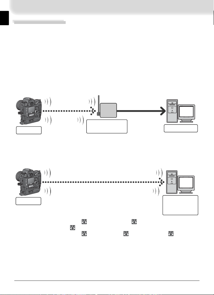
Wireless Networks
The WT-1 wireless transmitter is a wireless LAN adapter that allows photographs to be uploaded from the camera to an ftp server. Photographs can be
uploaded as they are taken, or photographs already on the camera memory
card can be selected for upload. The WT-1 supports the following two types
of network:
Infrastructure
Devices in an infrastructure network communicate via one or more wireless
access points. The WT-1 supports an infrastructure mode for connection to a
wireless network via an access point.
C
L
C
S
A
/
V
O
U
T
DC
I
N
WT-1
BUSY
BUSY
K
K
IN
IN
L
L
POWER
POWER
K
C
O
L
Wireless LAN
access point
햳햲
FTP server
Ad-hoc
Devices in an ad-hoc wireless network communicate directly (“peer-to-peer”),
without a wireless access point. The WT-1 supports an ad-hoc mode for direct
wireless connection to an ftp server.
C
L
C
S
A
/
V
O
U
T
DC
I
N
WT-1
BUSY
BUSY
K
K
IN
IN
L
L
POWER
POWER
K
C
O
L
햴
FTP server
(with wireless
LAN adapter)
햲 Confi gured using Wireless ( 15–17) and TCP/IP ( 17–21)
햳 Confi gured using FTP ( 21–25)
햴 Confi gured using Wireless ( 15–17), TCP/IP ( 17–21), and FTP ( 21–25)
An environment with an ftp server and a wireless LAN is required to use the
WT-1 (connection to an ftp server via the Internet is not supported). Operation has been confi rmed on the following systems: Windows XP Professional
and Windows 2000 Professional.
2
Page 10
Setup
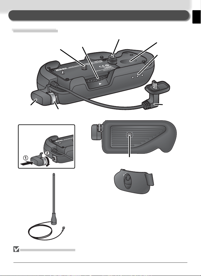
Parts of the WT-1
Mounting
screw
Knob
Power
contact
Housing
Status LEDs:
POWER
(green), LINK
(orange),
BUSY (green)
BUSY
LINK
CK
LO
POWER
Standard antenna
(WA-S1)
Antenna
connector
Attaching an antenna
Tripod socket
BL-2 battery-chamber cover
(for camera battery chamber)
WA-E1 extended range
antenna with tripod mount
(available separately)
Reorienting the Antenna
Before reorienting the antenna, unscrew it from the antenna connector.
USB cable
3
Page 11
LO
C
K
POW
ER
L
IN
K
B
U
SY
POW
ER
L
IN
K
B
U
SY
LO
C
K
POWERPOW
ER
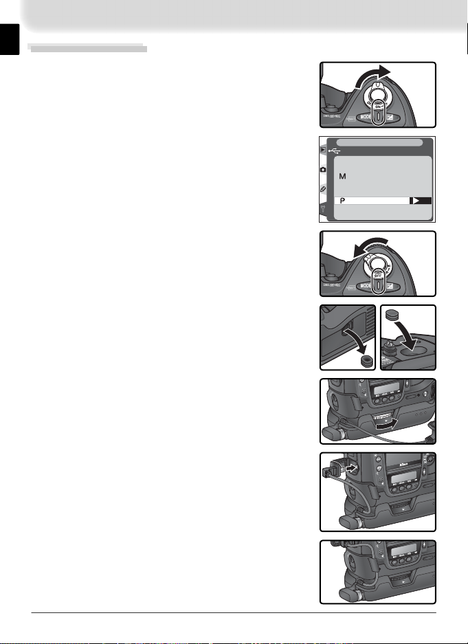
Attaching the WT-1
LO
C
K
POW
E
R
POW
E
R
Tu rn the camera on.
1
Before connecting the WT-1, set the USB option
2
in the camera setup menu to PTP.
Tu rn the camera off.
3
Remove the cover protecting the camera power
4
contact. The cover can be stored in the housing
on the WT-1.
Place the camera on the WT-1 and rotate the knob
5
in the direction shown to fasten the WT-1 to the
camera tripod mount.
Open the camera USB connector cover and con-
6
nect the USB cable to the USB connector.
SET UP
USB
Mass Storage
PTP
OK
Pass the cable over the guide on the BL-2 battery-
7
chamber cover.
4
Page 12

Wireless LAN Setup
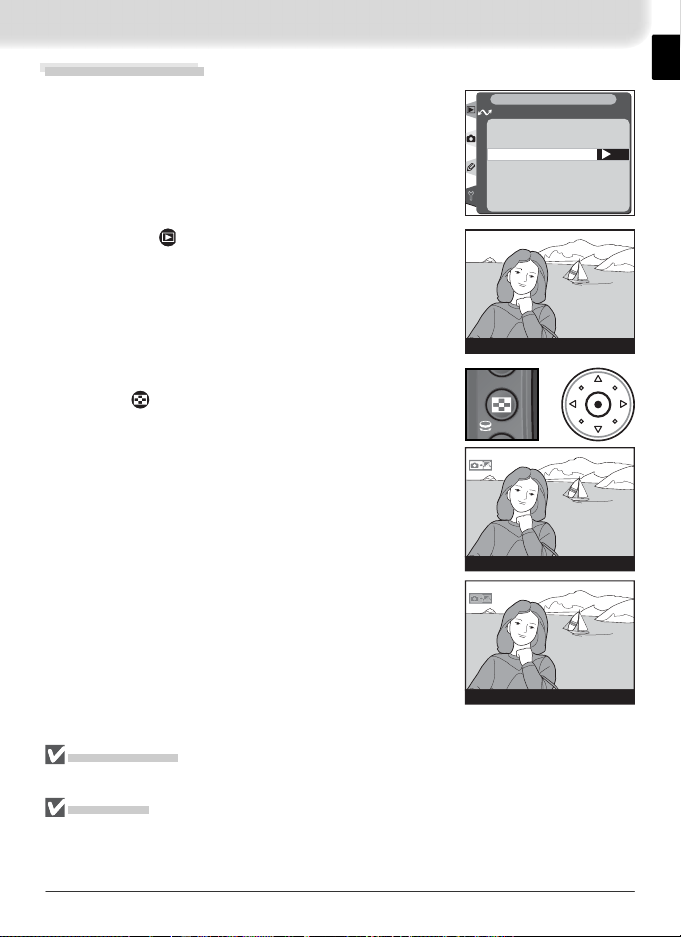
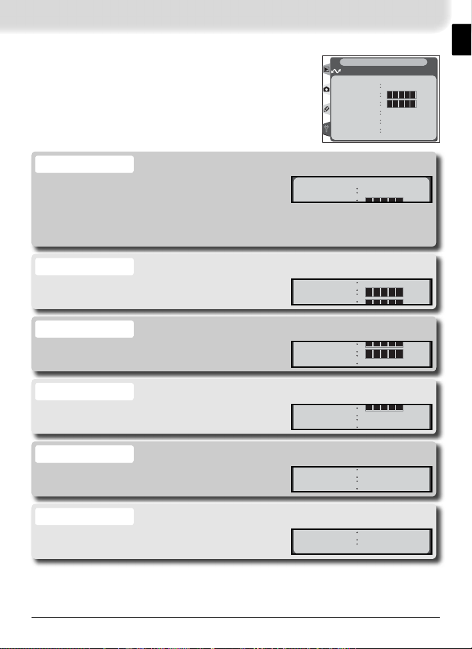
The Wireless LAN option in the camera setup
menu is available when the WT-1 is attached. See
the “Menu Guide” ( 12) for details.
SET UP
Wireless LAN
Tra n s ceiver
Status
Auto send
Send file as:
Send folder
Deselect all?
Network settings
OFF
OFF
RAW+J
Option
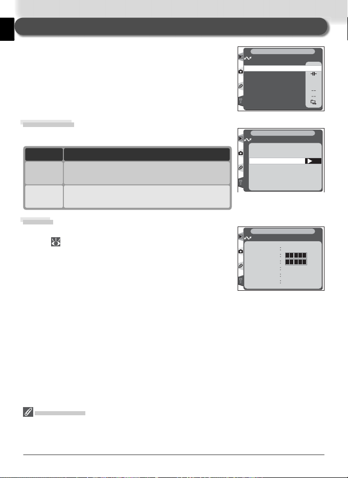
Transceiver
Status
Auto send
Send fi le as:
Send folder
Deselect all?
Network
settings
Description
Turn wireless LAN transceiver on or off.
Shows status of link between server and WT-1.
Choose whether to send pictures to server as they are taken.
12
12
13
Choose whether to send both NEF and JPEG fi les or only
JPEG fi les when sending images taken at settings of NEF +
13
JPEG Fine, NEF + JPEG Normal, or NEF + JPEG Basic.
Send all images in selected folder. Images will be sent in sequence, starting from lowest fi le number.
Remove transfer marking (“send,” “sending,” or “sent” indicators) from all fi les.
13
14
Adjust settings for connection to server. 14
5
Page 13
1
2
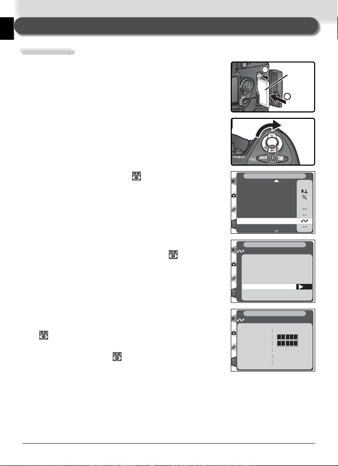
Uploading Images
Preparation
Insert the memory card containing the pictures to
be sent.
1
Tu rn the camera on.
2
Reverse
side
Adjust network settings ( 16–25).
3
Select On for the Wireless LAN > Tr ansceiver
4
option in the camera setup menu ( 12).
Select Status from the Wireless LAN menu and
5
confi rm that “Connected” is shown for “Status”
( 11). For information on what to do if the
camera shows “Not connected” or “Failure,” see
“Troubleshooting” ( 34).
6
SET UP
Voice memo protect
Voice memo button
Audio output
USB
Dust Off ref photo
Battery Info
Wireless LAN
Firmware Version
SET UP
Wireless LAN
Transceiver
Off
OFF
On
ON
SET UP
Wireless LAN
Status
Link quality
Signal level
Now sending
Remaining
Time left
Connected
0 Frames
0 s
ON
M
OK
Page 14
Uploading Images
Select Off for Wireless LAN > Auto send (if
1
Auto Send is on, new photographs can not be
selected for upload; instead, photographs will be
uploaded to the server as they are taken).
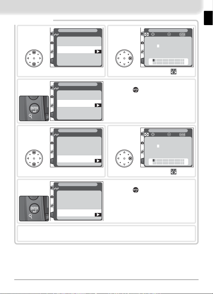
Press the button to view pictures on the
2
memory card. Display the fi rst picture to be sent
in single-image playback or highlight it in the
thumbnail list.
Press the center of the multi selector while press-
3
ing the button. The image will be marked with
a white “send” icon and transmission will begin
immediately. During upload, images are marked
with a green “sending” icon. Repeat this process
to send additional images (pictures will be sent in
the order selected).
Images that have been successfully uploaded are
marked with a blue “sent” icon.
SET UP
Wireless LAN
Auto send
Off
OFF
On
ON
OK
100-1
+
100-1
100-1
During Upload
Do not remove the memory card from the camera during upload.
File Names
If the destination folder on the ftp server contains fi les with the same names as fi les
selected for upload, the fi les on the server will be replaced by the fi les uploaded from
the camera.
7
Page 15
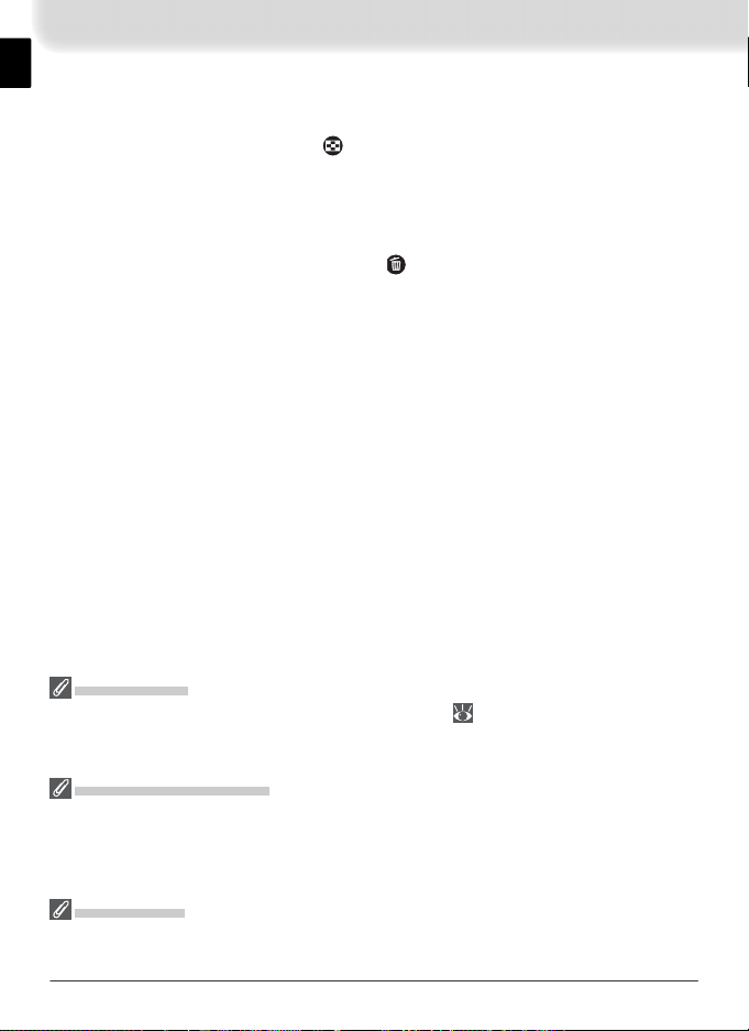
Interrupting Transmission
To cancel transmission of images marked with a white “send” icon or green
“sending” icon, select the images during playback and press the center of the
multi selector while pressing the button. The icon will be removed. Any of
the following actions will also interrupt transmission:
• Turning the camera off
• Choosing Off in the Wireless LAN > Tr ansceiver menu
• Selecting Deselect all? in the Wireless LAN menu
• Deleting the images by pressing the
button while the images are se-
lected
• Formatting the memory card
Loss of Signal
Transmission may be interrupted if the signal is lost ( 11). Transmission can be resumed by turning the camera off and then on again, activating the camera exposure
meters, or selecting On for Wireless LAN > Transceiver once the signal is restored.
Tur ning the Camera Off
“Send” marking will be saved if the camera is turned off or Off is selected for Wireless
LAN > Transceiver while transmission is in progress. Transmission of images marked
with a “send” icon will resume when the camera is turned on or On is selected for
Wireless LAN > Transceiver.
Voice Memos
Voice memos can not be uploaded separately, but will be included when the associated
pictures are transmitted.
8
Page 16
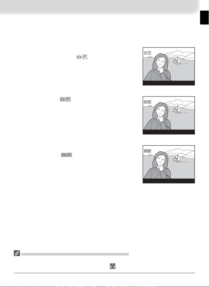
“Send,” “Sending,” and “Sent” Icons
The following icons are displayed when images selected for upload are viewed
during playback.
“Send”
Images that have been selected for upload are marked
with a white “send” icon (
).
100-1
“Sending”
During upload, the icon is displayed in green.
100-1
“Sent”
Images that have been uploaded successfully are
marked with a blue icon.
100-1
Removing “Send,” “Sending,” and “Sent” Icons
“Send,” “sending,” and “sent” icons can be removed from all images by selecting
Deselect all? from the Wireless LAN menu ( 14).
9
Page 17
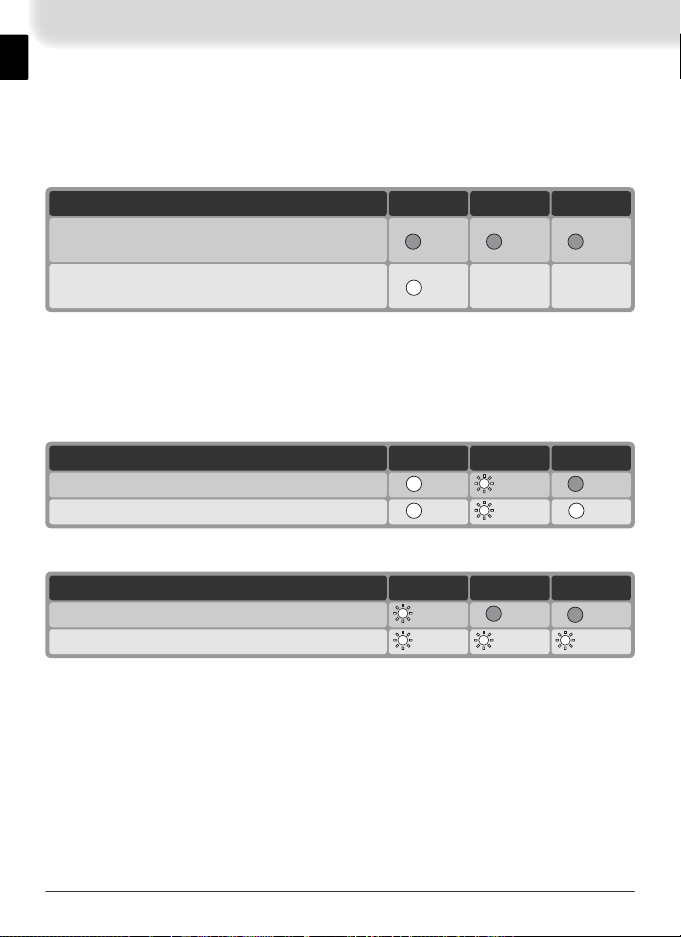
Network Status
The status of the link between the server and the WT-1 is shown by the status
LEDs and by the Status display in the Wireless LAN menu.
The Status LEDs
The POWER LED lights when the WT-1 is receiving power from the camera.
BUSYLINKPOWERStatus
Camera or exposure meters off, or Off selected
for Wireless LAN > Transceiver
Camera on and On selected for Wireless
LAN > Transceiver
* Blinks to indicate active connection.
† Lights while data are being transmitted.
(on)
(off) (off) (off)
N / A
*
N / A
*
The status of the link between the WT-1 and the server is shown by the LINK
LED, which blinks at different speeds to indicate link quality. The BUSY LED
lights while data are being sent.
BUSYLINKPOWERStatus
(off) (blinks) (on)Connecting to server
(on) (blinks) (on)Sending data
The following indicate that an error has occurred:
BUSYLINKPOWERStatus
(off) (off) (blinks)Connection error
(blinks) (blinks) (blinks)WT-1 hardware malfunction
10
Page 18
The Status Display
Status Connected
Remaining 1 Frames
Now sending
DSC_0001.JPG
Si
l
Link quality
Network status can also be viewed by selecting Status from the Wireless LAN menu.
Status
The status of the link between the server and the
camera.
• Connected: connection established
• Not connected: camera not currently connected
• Failure: can not establish connection
Link quality
A fi ve-level indicator of link quality. Transmission
speeds improve as quality increases.
Signal level
A fi ve-level indicator of signal strength.
Now sending
The name of the fi le currently being sent.
Status Connected
Link quality
Signal level
Now sending
Wireless LAN
Status
Link quality
Signal level
Now sending
Remaining 1 Frames
Time left
gnal leve
SET UP
Connected
DSC_0001.JPG
5 s
DSC_0001.JPG
Remaining
The number of images (frames) remaining to be
sent.
Time left
Estimated time required to send remaining data.
Changes with link quality and signal strength.
Remaining 1 Frames
Time left 5 s
11
Page 19
Menu Guide
This section describes the options available in the
Wireless LAN sub-menu of the camera setup menu.
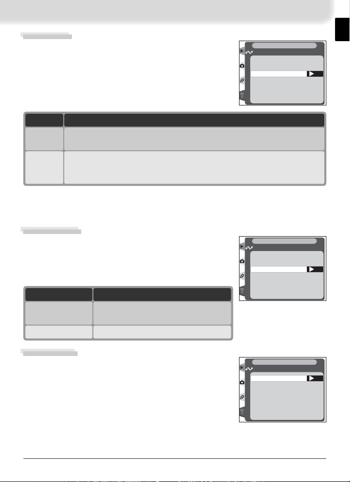
Transceiver
Turn the WT-1 transceiver on or off.
Option Description
Transceiver off. Camera can not communicate
Off
(default)
with server.
Transceiver on. Camera can communicate
On
with server.
Status
Current status of the link between the WT-1 and the
server ( 11).
SET UP
Wireless LAN
Tra n s ceiver
Status
Auto send
Send file as:
Send folder
Deselect all?
Network settings
SET UP
Wireless LAN
Transceiver
Off
OFF
On
ON
SET UP
Wireless LAN
Status
Link quality
Signal level
Now sending
Remaining 1 Frames
Time left
Connected
DSC_0001.JPG
5 s
OFF
OFF
RAW+J
OK
“Transceiver”
Transmission of images marked with a “send” icon begins as soon as On is selected for
Wireless LAN > Transceiver. When the transceiver is off, the WT-1 receives no power
from the camera. Select Off to reduce the drain on the batteries.
12
Page 20
Auto Send
Choose whether to upload pictures to the server as
they are taken.
SET UP
Wireless LAN
Auto send
Off
OFF
On
ON
OK
Option
Off
(default)
Pictures are not automatically uploaded to server as they are taken. Pictures can be selected for transmission when camera is in playback mode.
Description
Pictures are uploaded to server as they are taken.* Transmission begins
as soon as picture has been recorded to camera memory card. Be sure
On
memory card is inserted in camera before shooting.
* Pictures will not be uploaded to the server if Off is selected in the Wireless
LAN > Transceiver menu. Pictures will instead be marked with a “send” indicator as
they are recorded to the memory card.
Send File As:
When sending images taken at settings of NEF +
JPEG Fine, NEF + JPEG Normal, or NEF + JPEG
Basic, choose whether to send both NEF (RAW) and
JPEG fi les or only the JPEG fi les.
Option
NEF(Raw) + JPEG
(default)
JPEG only
Send both NEF (RAW) and JPEG fi les.
JPEG fi les are sent fi rst.
Send JPEG fi les only.
Description
SET UP
Wireless LAN
Send file as:
NEF(Raw) + JPEG
JPEG only
OK
Send Folder
All fi les in the selected folder (including those already
marked as “sent”) will be uploaded in ascending
order by fi le number. The folder itself will not be
SET UP
Wireless LAN
100NCD2H
OK
uploaded. Transmission begins when the folder is
selected.
13
Page 21
Deselect All
and right buttons on multi
.
Remove “send,” “sending,” and “sent” marking
from all images on the memory card.
Option
No
(default)
Yes
Marking is not removed.
Remove marking from all images and terminate
upload of images marked with “sending” icon.
Description
SET UP
Wireless LAN
Deselect all?
No
Ye s
OK
Network Settings
Adjust settings for connection to the server. Settings created using a computer can be loaded from
a memory card (
15), or network settings can be
adjusted individually using the camera menus ( 15–
25; sample settings are listed on page 26). To ensure
that the monitor does not power off before changes
SET UP
Wireless LAN
Network settings
Load settings file?
Wireless
TCP/IP
FTP
to settings are complete, choose a long monitor off
delay or use an AC adapter when adjusting settings
manually.
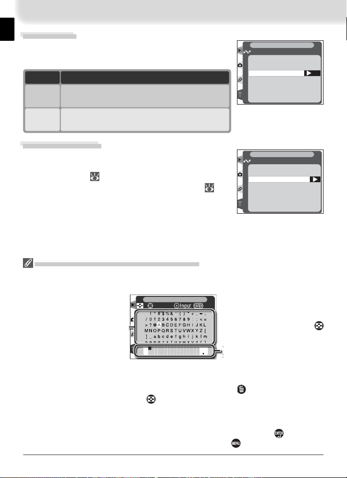
Text Entry in the “Network Settings” Menu
If text entry is required to complete the selected setting, the following dialog will be
displayed.
SET UP
+
Keyboard area
cursor OK
Use multi selector to highlight letters, press center
to select.
Use the multi selector to highlight the desired character in the keyboard area and press
the center of the multi selector to insert the highlighted character at the current cursor
position. To delete the character under the cursor, press the button. To move the
cursor to a new position, press the button while using the multi selector. No more
than thirty-two characters can be entered; if additional characters are entered when the
display is full, all characters after the thirty-third will be deleted.
To complete entry and return to the Network settings menu, press the button. To
exit to the setup menu without completing text entry, press .
Text display area
Text appears in this area.
To move cursor, press
while using up, down, left,
elector
14
Page 22
Load Settings File
Network settings created with a computer can be
saved to the camera memory card.
Option
No
(default)
Yes
Exit without changing settings.
Load Wireless, TCP/IP, and FTP settings from
the memory card.
Description
SET UP
Wireless LAN
Load settings file?
No
Ye s
OK
Wireless
Adjust settings for connection to a wireless network
as described on the following pages.
SET UP
Wireless LAN
Wireless
Communication mode
SSID
Encryption
Channel
Communication Mode
Choose a mode according to how the wireless network is set up.
Option
Infrastructure
(default)
Ad-hoc
Connection to wireless network is via access point.
Direct peer-to-peer wireless connection
to ftp server.
Creating a Settings File
An application for creating settings fi les is available from the web sites listed on page 1
of this manual. After creating a settings fi le, save it to the root directory of the camera
memory card using a CompactFlash card reader or PCMCIA memory card adapter. No
more than one settings fi le should be stored on the memory card at a time. Additional
information is available from the download site.
Description
SET UP
Wireless LAN
Communication mode
Infrastructure
Ad-hoc
OK
15
Page 23
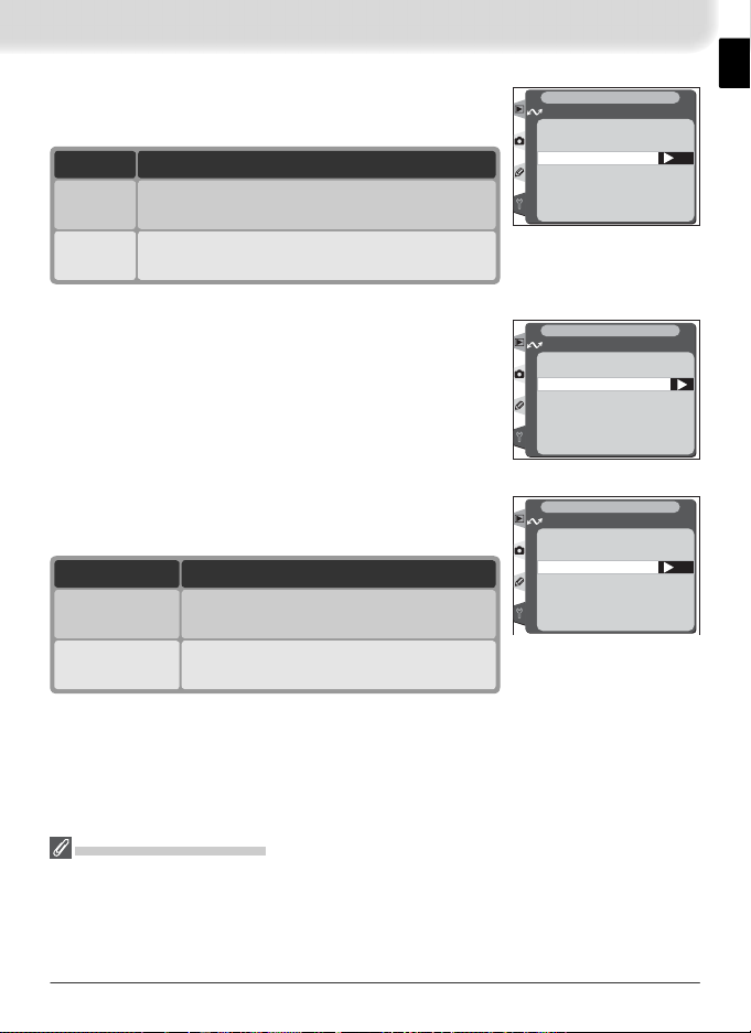
SSID
A BSS- or ESS-ID is required for connection to a wireless LAN adapter or access point. Leave this fi eld
SET UP
Wireless LAN
SSID
blank to allow network to set SS-ID automatically
(“any” connection). To change the current BSS- or
ESS-ID, press the multi selector to the right and enter
an ID as described on page 14. Press the
button to
return to the SS-ID display.
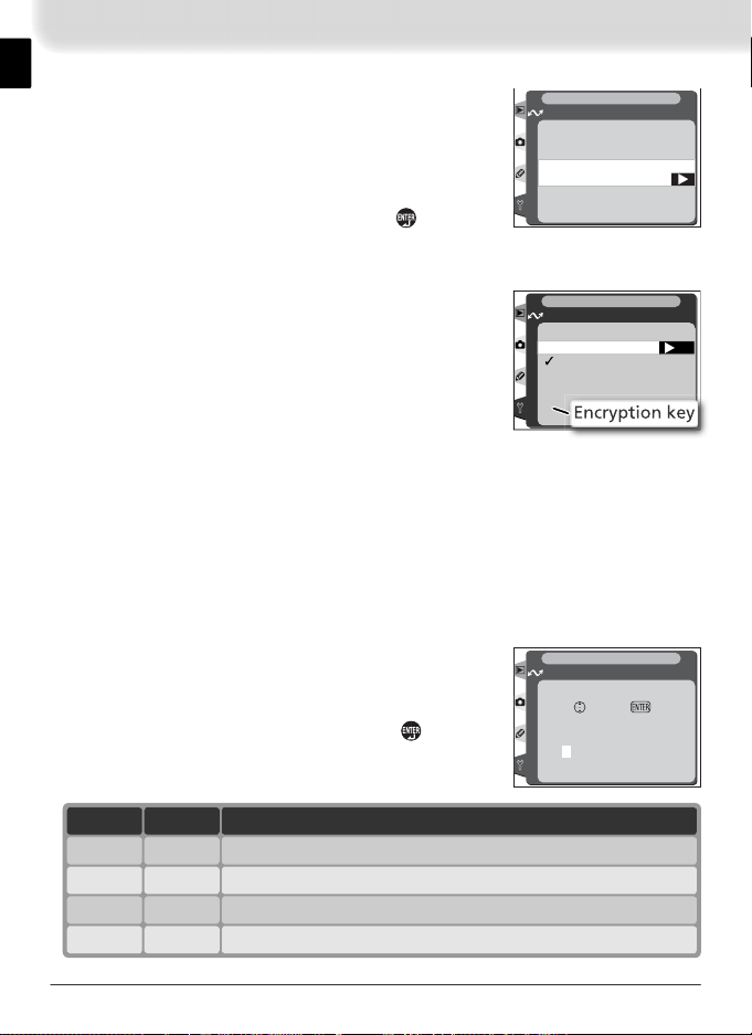
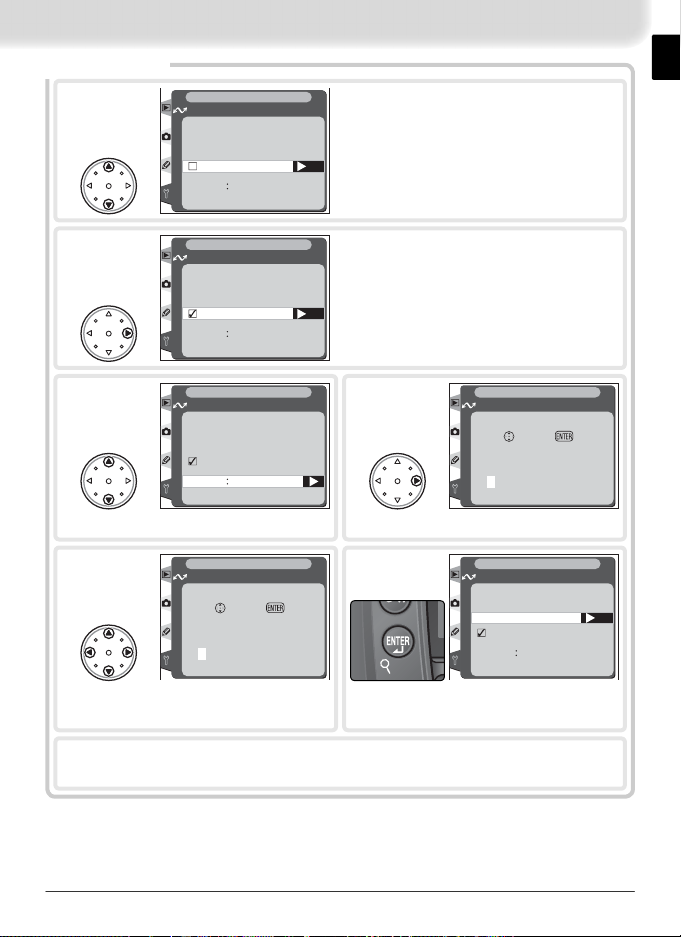
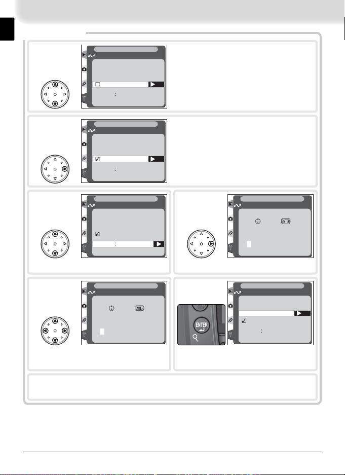
Encryption
Enter encryption settings according to how the network is set up. Press the multi selector up or down
to highlight an option and press the multi selector to
the right to select.
• Done: Save changes and exit to wireless menu.
SET UP
Wireless LAN
Encryption
Done
□
On
□
Base 16
□
128 bit
OK
• On: Enable or disable encryption. ✔ appears when
encryption is enabled.
• Base 16: Enable or disable base-16 encryption. ✔ appears when base-16
encryption is enabled. Enable base-16 encryption to enter encryption key
in hexadecimal notation using only numbers 0–9 and letters A–F. Disable
base-16 encryption to enter encryption key in ASCII notation using standard
alphanumeric characters.
• 128 bit: Enable or disable 128-bit encryption. ✔ appears when 128-bit en-
cryption is enabled. If 128-bit encryption is disabled, 40-bit encryption will
be used.
• Encryption key: Highlight current key and press
multi selector to right to display edit dialog shown
at right. Press multi selector left or right to select
SET UP
Wireless LAN
Encryption
Set
OK
character, up or down to change. Press to return
to encryption menu. Length of key depends on
0000000000
options selected for Base 16 and 128 bit:
16
Base 16
✔
—
✔
Encryption key128 bit
Five characters (ASCII)——
— Te n characters (hexadecimal)
✔
✔
Thirteen characters (ASCII)
Twenty-six characters (hexadecimal)
Page 24
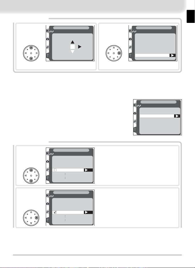
1
*
Wireless LAN
Channel
Choose channel.
SET UP
01
†
SET UP
2
OK
Wireless LAN
Wireless
Communication mode
SSID
Encryption
Channel
Return to wireless menu.
Channel
* Not required if Infrastructure is selected for Communication mode.
† The WT-1 offers a choice of thirteen channels (1–13), the WT-1A a choice of eleven
channels (1–11).
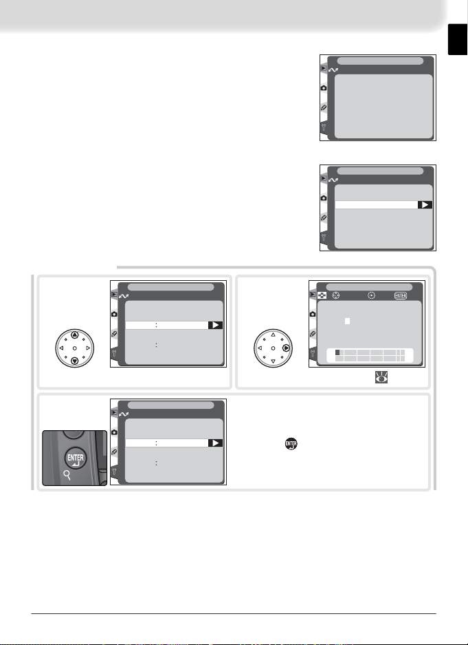
TCP/IP
Adjust TCP/IP settings as described on the following
pages.
SET UP
Wireless LAN
TCP/IP
IP address
Gateway
DNS
MAC address
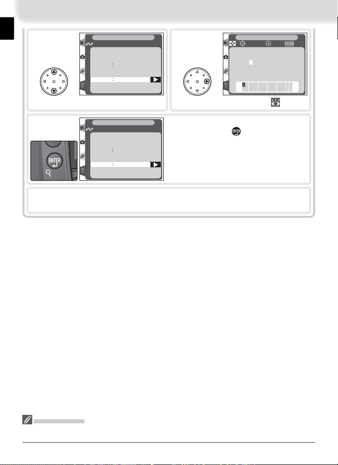
IP Address
1
2
* Required.
*
SET UP
Wireless LAN
IP address
Done
Obtain automatically
Address
000.000.000.000
Mask
000.000.000.000
SET UP
Wireless LAN
IP address
Done
Obtain automatically
Address
000.000.000.000
Mask
000.000.000.000
Highlight Obtain automatically.
Set
Tur n ✔ on or off. If wireless network is
confi gured to supply IP address automatically, turn ✔ on and proceed to Step 11.
Otherwise remove ✔ and enter IP address
Set
and subnet mask provided by network administrator (Steps 3–10).
17
Page 25
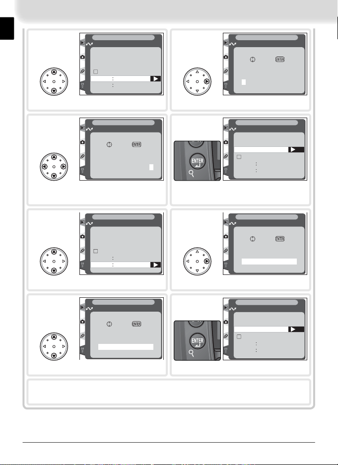
3
SET UP
Wireless LAN
IP address
Done
Obtain automatically
Address
000.000.000.000
000.000.000.000
Mask
4
SET UP
Wireless LAN
IP address
Set
Address
000.000.000.000
OK
Highlight Address.
SET UP
5
Wireless LAN
IP address
Set
Address
192.168.001.002
OK
Press multi selector left or right to se-
lect, up or down to change.
SET UP
7
Wireless LAN
IP address
Done
Obtain automatically
Address
192.168.001.002
000.000.000.000
Mask
Highlight Mask.
SET UP
9
Wireless LAN
IP address
Set
Mask
255.255.255.000
OK
Choose subnet mask.
6
Exit to IP address menu. If no subnet
mask is required, proceed to Step 11.
8
10
Enter edit mode.
SET UP
Wireless LAN
IP address
Done
Obtain automatically
192.168.001.002
Address
000.000.000.000
Mask
SET UP
Wireless LAN
IP address
Set
Mask
000.000.000.000
Enter edit mode.
SET UP
Wireless LAN
IP address
Done
Obtain automatically
Address
192.168.001.002
255.255.255.000
Mask
Exit to IP address menu.
Highlight Done and press multi selector to right to return to TCP/IP menu.
11
OK
OK
OK
18
Page 26
Gateway
1
SET UP
Wireless LAN
Gateway
Done
Use gateway
Address 000.000.000.000
Highlight Use gateway.
Set
SET UP
2
3
5
Press multi selector left or right to se-
lect, up or down to change.
Highlight Done and press multi selector to right to return to TCP/IP menu.
Wireless LAN
Gateway
Done
Use gateway
Address 000.000.000.000
SET UP
Wireless LAN
Gateway
Done
Use gateway
Address 000.000.000.000
Highlight Address.
SET UP
Wireless LAN
Gateway
Set
Address
100.000.000.000
Tur n ✔ on or off. If network requires
gateway address, turn ✔ on and enter
address provided by network administrator (Steps 3–6). Otherwise remove ✔ and
Set
proceed to Step 7.
4
6
OK
Return to gateway menu.
Wireless LAN
Gateway
Address
000.000.000.000
Enter edit mode.
Wireless LAN
Gateway
Done
Use gateway
Address 192.168.001.254
SET UP
Set
SET UP
7
OK
OK
19
Page 27
DNS
1
SET UP
Wireless LAN
DNS
Done
Enable DNS
Address 000.000.000.000
Highlight Enable DNS.
Set
SET UP
2
3
5
Press multi selector left or right to se-
lect, up or down to change.
Highlight Done and press multi selector to right to return to TCP/IP menu.
Wireless LAN
DNS
Done
Enable DNS
Address 000.000.000.000
SET UP
Wireless LAN
DNS
Done
Enable DNS
Address 000.000.000.000
Highlight Address.
SET UP
Wireless LAN
DNS
Set
Address
100.000.000.000
Tur n ✔ on or off. If Domain Name Server
(DNS) exists on network, turn ✔ on and
enter DNS address provided by network
administrator (Steps 3–6). Otherwise re-
Set
move ✔ and proceed to Step 7.
4
6
OK
Return to DNS menu.
Wireless LAN
DNS
Address
000.000.000.000
Enter edit mode.
Wireless LAN
DNS
Done
Enable DNS
Address 192.168.001.019
SET UP
Set
SET UP
7
OK
OK
20
Page 28
MAC Address
This fi eld lists the twelve-digit Media Access Control
(MAC) address for the WT-1.
SET UP
Wireless LAN
MAC address
02-FF-FF-FF-03-02
FTP
Adjust ftp settings as described on the following
pages.
*
Server
SET UP
1
3
* Required.
Wireless LAN
Server
Address
Folder
Highlight Address.
SET UP
Wireless LAN
Server
Address
192.168.1.3
Folder
2
Display text entry dialog ( 14).
Enter address of ftp server to which pictures are to be uploaded (if unsure of correct address, contact server administrator). Press button to return to server
menu.
SET UP
Wireless LAN
FTP
Server
User
Proxy
Advanced
SET UP
cursor OKInput
+
!"#$%&'()*+,–.
/ 0123456789 : ;<=
>?@A BCDEFGH I JKL
MNOPQRST UVWXYZ [
] _abcde fgh i jk lm
nopqr s t uvwxyz { }
21
Page 29
4
SET UP
Wireless LAN
Server
Address
192.168.1.3
Folder
5
SET UP
cursor OKInput
+
!"#$%&'()*+,–.
/ 0123456789 : ;<=
>?@A BCDEFGH I JKL
MNOPQRST UVWXYZ [
] _abcde fgh i jk lm
nopqr s t uvwxyz { }
Highlight Folder.
SET UP
6
Press multi selector to left to return to ftp menu.
Wireless LAN
Server
Address
192.168.1.3
Folder
/
After entering name of destination folder
on ftp server, press button to return to
server menu.
7
Display text entry dialog ( 14).
Folder Names
Folder names are not case sensitive.
22
Page 30
User
1
*
SET UP
Wireless LAN
User
User ID
Password
2
SET UP
cursor OKInput
+
!"#$%&'()*+,–.
/ 0123456789 : ;<=
>?@A BCDEFGH I JKL
MNOPQRST UVWXYZ [
] _abcde fgh i jk lm
nopqr s t uvwxyz { }
Highlight User ID.
SET UP
3
4
Highlight Password.
6
Press multi selector to left to return to ftp menu.
Wireless LAN
User
User ID
anonymous
Password
SET UP
Wireless LAN
User
User ID
anonymous
Password
SET UP
Wireless LAN
User
User ID
anonymous
Password
7
* Required.
Display text entry dialog ( 14).
After entering user name for login to ftp
server, press button to return to user
menu.
SET UP
+
5
Display text entry dialog ( 14).
After entering password for login to ftp
server, press button to return to user
menu. Password will be disguised as row
of dots when displayed in ftp menu.
cursor OKInput
!"#$%&'()*+,–.
/ 0123456789 : ;<=
>?@A BCDEFGH I JKL
MNOPQRST UVWXYZ [
] _abcde fgh i jk lm
nopqr s t uvwxyz { }
23
Page 31

Proxy
1
SET UP
Wireless LAN
Proxy
Done
Use proxy server
Address
000.000.000.000
0
Port
Highlight Use proxy server.
Set
SET UP
2
3
Wireless LAN
Proxy
Done
Use proxy server
Address
000.000.000.000
0
Port
SET UP
Wireless LAN
Proxy
Done
Use proxy server
Address
000.000.000.000
0
Port
Highlight Address.
SET UP
5
Wireless LAN
Proxy
Set
Address
100.000.000.000
Press multi selector left or right to se-
lect, up or down to change.
Tur n ✔ on or off. If proxy server is re-
quired for ftp, turn ✔ on and enter ad-
dress and port number (Steps 3–6). Otherwise remove ✔ and proceed to Step 7.
Set
4
Wireless LAN
Proxy
Address
000.000.000.000
Enter edit mode.
6
OK
Wireless LAN
Proxy
Done
Use proxy server
Address
Port
Return to proxy menu. Repeat steps
3–6 to enter Port number.
Highlight Done and press multi selector to right to return to ftp menu.
7
SET UP
OK
Set
SET UP
192.168.001.254
0
24
Page 32

Advanced
1
SET UP
Wireless LAN
Advanced
Done
PA SV mode
Port 0
Highlight PASV mode.
Set
2
3
5
6
SET UP
Wireless LAN
Advanced
Done
PA SV mode
Port 0
SET UP
Wireless LAN
Advanced
Done
PA SV mode
Port 0
Highlight Port.
SET UP
Wireless LAN
Advanced
Set
Por t
SET UP
Wireless LAN
Advanced
Done
PA SV mode
Port 21
00021
Tur n ✔ on or off. Turn ✔ on to instruct
ftp server to use PASV mode (be sure server supports PASV mode before turning
this option on). Turn ✔ off to use normal
Set
(PORT) mode.
4
Enter port number for ftp connection (if
required). Press multi selector left or right
to select digit, up or down to change.
OK
Highlight Done and press multi
selector to right to return to ftp
7
OK
menu.
Wireless LAN
Advanced
Por t
Enter edit mode.
SET UP
Set
00000
OK
Return to advanced menu.
25
Page 33

Appendices
Sample Network Settings
The following pages describe how to set up a simple infrastructure network
using the WT-1 and a Windows XP Professional ftp server. Encryption and
network security are not discussed.
1—Preparation....................................................... 26
2—Building a Network........................................... 26
3—Confi guring the Server ................................ 27–28
4—Confi guring the Wireless LAN Adapter ............. 29
5—Confi guring the WT-1.................................. 30–31
6—Uploading Pictures....................................... 31–33
Preparation
Ready the following items:
• D2H digital camera • WT-1 wireless transmitter
• ftp server 1 • wireless LAN adapter
1
Windows XP Professional computer with Internet Information Services (IIS) installed.
2
Bridge type. Additional settings may be required when using wireless router. See
documentation provided by manufacturer for details.
Building a Network
Confi gure the network as shown below. In this example, the wireless LAN
access point is connected by a cable to the server, and the server is not connected to any other network devices.
2
26
A
/
V
O
U
T
DC
IN
C
L
C
S
WT-1
LAN cable
Y
Y
S
S
U
U
B
B
NK
NK
I
I
L
L
R
R
E
E
POW
POW
K
C
O
L
Wireless LAN
access point
FTP server
Page 34

Confi guring the Server
The following example assumes that Windows XP Professional and Internet
Information Services (IIS) are already installed (IIS is included in the standard
install of Windows XP Professional; for more information, contact Microsoft).
Be sure to use characters supported by the WT-1 (
settings as user ID, password, and folder names.
Entering an IP Address
Open the Network Connections control panel.
Right-click the Local Area Connection icon and select Properties from the menu that appears.
The “Local Area Connection Properties” dialog will be displayed. Select In-
ternet Protocol (TCP/IP) and click Properties to display the “Internet Proto-
col (TCP/IP)” dialog. Enter an IP address and subnet mask for the ftp server.
14) when specifying such
In this example, it is assumed that the network uses class C private IP addresses and subnet masks. Be sure that the IP address is not the same as that
assigned to the wireless LAN adapter or the WT-1. For example, if the ftp
server is given the IP address 192.168.1.3, the wireless LAN adapter can be
assigned 192.168.1.1, and the WT-1 192.168.1.2. All addresses must be in
the same class.
27
Page 35

Creating an FTP Site
Go to Administrative Tools and open the Internet
Information Services console. Right-click the De-
fault FTP site folder and choose Properties from the
menu that appears.
The “Default FTP Site Properties” dialog will be displayed. Open “Security Accounts” and select Allow
Anonymous Connections and Allow IIS to control
password. Make sure the default user ID (composed
of “IUSR” plus the computer name) is unchanged and
leave the password fi eld blank.
Next, open “Home Directory” and select A directory located on this com-
puter. The root directory for images uploaded to the ftp server is listed in
the Local Path text box; choose a folder and check Read, Write, and Log
visits.
Before proceeding to the next step, click OK to close the properties dialog.
28
Page 36

Confi guring the Wireless LAN Adapter
The minimum information needed to confi gure a wireless LAN adapter is
listed below. Contact the manufacturer for details.
Wireless mode 802.11b
SS-ID 1D2H
Encryption (WEP) Off
“Any” connection 2Disabled
Channel Any
IP address 3Obtain IP address automatically: Off
Default gateway 000.000.000.000
MAC address 4Unspecifi ed
1
Same SS-ID must be assigned to WT-1.
2
Not required if adapter does support “any” connection.
3
In this example, it is assumed that network uses class C private IP addresses and
subnet masks. Be sure that IP address is not same as that assigned to ftp server or
WT-1. For example, if ftp server is 192.168.1.3, wireless LAN adapter can be assigned
192.168.1.1, and WT-1 can be assigned 192.168.1.2. All addresses must be in same
class.
4
If MAC address is required, enter MAC address for WT-1 ( 21).
IP address: 192.168.1.1
Subnet mask: 255.255.255.000
DNS 000.000.000.000
29
Page 37

Confi guring the WT-1
Before adjusting network settings as shown below,
select Off in the Wireless LAN > Tr ansceiver menu.
SET UP
Wireless LAN
Transceiver
Off
OFF
On
ON
Wireless
Communication mode Infrastructure
SSID 1D2H
Encryption Disabled
Channel —
1
Same SS-ID must be assigned to wireless LAN adapter.
TCP/IP
IP address 1Obtain IP address automatically: Off
Gateway Disabled
1
In this example, it is assumed that network uses class C private IP addresses and sub-
net masks. Be sure that IP address is not same as that assigned to ftp server or wireless
LAN adapter. For example, if ftp server is 192.168.1.3, wireless LAN adapter can be
assigned 192.168.1.1, and WT-1 can be assigned 192.168.1.2. All addresses must be
in same class.
IP address: 192.168.1.2
Subnet mask: 255.255.255.000
DNS Disabled
OK
30
Page 38

FTP
Server Address: 192.168.1.3
Folder: /
2
User User ID: anonymous
Password:
Proxy Disabled
PASV mode Disabled
1
Enter address assigned ftp server ( 27).
2
Choose “/” to upload to root directory on ftp server ( 28).
1
Uploading Pictures
This section describes how to upload pictures as they are taken. For best results, the WT-1 and wireless LAN adapter should be within a few meters with
no obstacles between them.
Select On for the Wireless LAN > Tr ansceiver
1
option in the camera setup menu.
SET UP
Wireless LAN
Transceiver
Off
OFF
On
ON
OK
Confi rm that a connection has been established.
2
To check the connection from the camera, select Status from the Wireless LAN menu and
confi rm that “Connected” is displayed next to
“Status.” For information on what to do if the
camera shows “Not connected” or “Failure,” see
“Troubleshooting” ( 34).
Wireless LAN
Status
Link quality
Signal level
Now sending
Remaining
Time left
SET UP
Connected
0 Frames
0 s
31
Page 39

To check the status of the connection from the computer, right-click the
Default FTP site folder and select Properties from the menu that appears. Open “FTP Site” and click Current Sessions….
Confi rm that “Anonymous” is listed under “Connected Users.” For information on what to do if no connection is listed, see “Troubleshooting”
(
34).
32
Page 40

Select On for Wireless LAN > Auto send. Take a
3
picture and confi rm that the image has been uploaded to the specifi ed folder on the ftp server.
SET UP
Wireless LAN
Auto send
Off
OFF
On
ON
OK
33
Page 41

Troubleshooting
Problem Solution
“POWER” LED does not light.
All LEDs blink at once.
Excessive radio interference.
Connection status shows “Not connected” or “Failure,” or ftp server
does not list connection.
• Turn camera on.
• Press shutter-release button halfway
to activate exposure meters.
• Reattach WT-1.
WT-1 hardware error. Contact a
Nikon-authorized service representative.
Change orientation of camera or antenna.
Turn transceiver off and check settings
for WT-1, wireless LAN adapter or access point, and ftp server.
4
—
4
—
—
26
34
Page 42

Glossary
Ad-hoc
Devices in an ad-hoc wireless network communicate directly (“peer to peer”), without
a wireless access point. The WT-1 supports an ad-hoc mode for direct wireless connection to an ftp server.
“Any” connection
Allows devices to connect to wireless network without an SS-ID. Can be used for wireless “hot spots” but is not as secure as connections that require an SS-ID.
BSS-ID (Basic Service Set ID)
All wireless devices on an ad-hoc wireless network share the same BSS-ID. The BSS-ID
may be up to thirty-two characters long and is case sensitive. See also Ad-hoc.
Channel
When multiple wireless LANs with different ESS-IDs are operating on a single frequency
within a given area, transmission speeds will drop. Specifying a separate channel (frequency) for each network can prevent interference and increase transmission speeds
(note that all devices in the same network must be set to the same channel). In the
IEEE 802.11b standard, the 2.4 GHz band is divided into 14 channels, each separated
by 4 MHz.
DHCP (Dynamic Host Confi guration Protocol) Server
Each device in a TCP/IP network requires an IP address. If a DHCP server is present on
the network, IP addresses will be assigned automatically. A DHCP server will not be
present on networks that consist solely of Windows Me, Windows 98, or Windows 95
computers. DHCP may be enabled on other networks; consult the network administrator or see the manual provided with the router or operating system.
DNS (Domain Name Server)
A server that contains a database of IP addresses and host names for the machines it
administers and that converts host names to IP addresses in response to queries from
clients. Each DNS can also query other Domain Name Servers for addresses not listed
in its database.
ESS-ID (Extended Service Set ID)
Multiple BSSs can be confi gured to form an ESS, allowing users to roam between
wireless access points. Only devices with the same ESS-ID as a given access point can
communicate with that access point. The ESS-ID may be up to thirty-two characters
long and is case sensitive.
IIS (Internet Information Services)
Microsoft’s name for its Web server software. Notable for its close connection to Windows-based systems through Active Server Pages (ASPs). When installed as part of the
operating system, IIS makes it relatively easy to build web a server.
35
Page 43

Gateway
A network node that acts as an entrance to another network, for example between a
company network and the Internet.
Infrastructure
Devices in an infrastructure network communicate via one or more wireless access
points. The WT-1 supports an infrastructure mode for connection to a wireless network
via an access point.
IP address
Address given to each node in a TCP/IP network. All nodes in a TCP/IP network must
have a unique IP address. Private IP addresses are recommended for nodes that are part
of a local network.
LAN (Local Area Network)
A network of computers located in relatively close proximity to one another. LANs
generally support data transfer speeds of 10–100 Mbps.
MAC (Media Access Control) Address
A unique hardware address for each device on a network, required when sending and
receiving packets.
PASV mode
PASV mode is used by clients behind fi rewalls, when it allows the ftp server to supply
the port number.
Private IP address
An IP address that is only visible within a local network. Because packets using a
private IP address can not be transmitted to another network, they are usually sent
between networks via a proxy server or NAT. Private IP addresses in the range 10.0.0.0–
10.255.255.255 are termed “class A.” Class B addresses are in the range 172.16.0.0–
172.31.255.255, class C addresses in the range 192.168.0.0–192.168.255.255. The
class of address used depends on the size of the network. Class C addresses are often
used for small networks.
Protocol
A set of rules for passing information back and forth between devices in a network. By
defi ning such elements of communication as how links are established, how receipt of
a signal is acknowledged, how data are encoded, and how to handle errors, a protocol
ensures that data are transmitted without loss of information.
Proxy
A server that stands between large networks and local networks or computers, typically
to ensure security. One element of a fi rewall.
36
Page 44

Routing
The process of choosing a route for information packets to ensure that they reach the
correct destination. Devices or software that perform this task are known as “routers.”
SS-ID
An SS-ID prevents interference between devices in different networks.
Subnet mask
A mask that divides a network into subnets.
TCP/IP (Transmission Control Protocol/Internet Protocol)
A dual protocol consisting of a transport-layer protocol (TCP) that divides data into
packets which it later reassembles, and a network protocol (IP) that handles transmission of the packets between points in the network. It can be implemented on different
platforms, allowing data to be transmitted between machines with different operating
systems.
USB (Universal Serial Bus)
A standard for connecting peripheral devices. USB supports data transfer rates of up to
480 Mbps (USB 2.0). Devices connected via USB can be connected and disconnected
with the power on (“hot plug”) and do not require separate IRQ (interrupt request)
numbers, preventing confl icts with other devices.
WEP (Wired Equivalent Privacy)
A privacy protocol intended to provided users of wireless networks with the same level
of privacy as a wired network. When using WEP, enter the encryption key provided by
the network administrator.
Wireless LAN access point
A wireless transceiver that acts as the connection between wireless devices and a wireless network.
37
Page 45

Specifi cations
Standards
Communication
protocols
(line of sight)
Operating
frequency
Current
consumption
consumption
Operating
environment
Dimensions
(W × H × D)
IEEE 802.11b
(standard for low power data communications systems)
Direct Sequence Spectrum Spread (DS-SS); single (half duplex)
Approximately 30 m (98´) with WA-S1 standard antenna
Range
Approximately 150 m (492´) with WA-E1 extended range antenna
and large antenna at wireless LAN access point
WT-1: 2412–2472
WT-1A: 2412–2462
1, 2, 5.5, and 11 MbpsData rates
128/64-bit (104/40-bit) WEPSecurity
Infrastructure / ad-hocAccess protocols
Sleep: 150 mA maximum (at input voltage of 13.5 V)
Send: 220 mA maximum (at input voltage of 13.5 V)
Power
3 W maximum
Temperature: 0–40 °C (32–131 °F)
Humidity: less than 85% (no condensation)
220 g / 7.8 oz (excluding antenna)Weight
146.5 mm × 34.5 mm × 65.5 mm (5.8˝ × 1.4˝ × 2.6˝)
(standard wireless LAN protocol)
MHz (13 channels)
MHz (11 channels)
, ARIB STD-T66
38
Page 46

Index
A
Access point. See Wireless
access point
Antenna, 3
Auto send, 13
B
BSS-ID, 16, 35
BUSY, 3, 10
C
Channel, 17, 35
selection, 17
Connecting the WT-1, 4
D
Deselect all?, 14
DHCP, 35
Domain Name Server (DNS)
address, 20, 35
DNS, 20, 35
E
Encryption, 16, 29
key, 16
ESS-ID, 16, 35
F
Folders, 5, 13
FTP, 21
ftp, 2, 21, 28, 31
folder, 22
password, 23
PASV mode, 25
port number, 24, 25
proxy, 21
server, 2, 21
settings, 21
user ID, 23, 28
G
Gateway, 19, 35
Gateway address, 19
I
IP address, 17, 27, 29, 37
L
LAN, 2, 36
LED. See Status LEDs; BUSY;
LINK; POWER
LINK, 3, 10
Link quality, 11
Link status, 10, 12
Load settings fi le?, 15
M
MAC address, 21 ,29, 37
Mounting screw, 3
N
Network settings, 14
Network settings fi les, 14
P
Password, 23
POWER, 3, 34
Power contact, 3
S
Send folder, 13
“Send” marking, 14
Send fi le as, 13
“Sending” marking, 14
“Sent” marking, 14
Settings fi les. See Network
settings fi les; Load set-
tings fi le
Signal strength, 11
SS-ID, 16, 21, 37
Status, 10–12
Status. See Link status; Status
LEDs
Status LEDs, 3, 10
Subnet mask, 17–18, 27, 37
T
TCP/IP, 17
TCP/IP, 17, 27, 30, 37
Transceiver, 12
U
Upload, 6
interrupting, 8
preparing camera for, 6
selecting images for, 7
USB, 4
USB, 4, 37
cable, 3, 4
connector, 4
setup, 4
User ID, 23, 28
V
Voice memos, 8
W
WEP, 29, 37, 38
Wireless, 15
Wireless access point, 2, 37
Wireless LAN, 2, 5
Wireless LAN, 2, 5, 29
confi guration, 29
39
Page 47

Système de communication
sans fi l
C
L
C
S
A
/
V
O
U
T
D
C
IN
Y
Y
S
S
U
U
B
B
LINK
LINK
R
R
E
E
POW
LOCK
POW
Fr
Manuel de l'utilisateur
Page 48

Informations sur les marques commerciales
Mac OS est une marque déposée d’Apple Computer, Inc. Internet est une marque commerciale de Digital Equipment
Corporation. Microsoft et Windows sont des marques déposées de Microsoft Corporation. Tous les autres noms
mentionnés dans ce manuel ou dans les autres documentations fournies avec ce produit Nikon sont des marques
commerciales ou des marques déposées de leurs détenteurs respectifs.
Page 49

Pour votre sécurité
Pour ne pas risquer d’endommager votre matériel Nikon ou de vous blesser, vous ou
d’autres personnes, prenez soin de lire attentivement les recommandations suivantes
avant d’utiliser votre matériel. Gardez ensuite précieusement ces consignes de sécurité
dans un endroit facilement accessible à tous ceux qui se serviront de cet appareil photo.
Les conséquences dues au non-respect de ces consignes sont symbolisées de la manière
suivante:
Cette icône signale les avertissements et consignes qui doivent être impérativement lus
avant d’utiliser votre matériel Nikon car ils concernent un possible danger physique.
AVERTISSEMENTS
Ne démontez pas votre matériel
Le non-respect de cet avertissement peut provoquer un incendie, un choc électrique ou toute autre blessure.
Si le produit devait s’ouvrir suite à une chute ou tout autre accident, déconnectez la source d’alimentation de
l’appareil photo et confi ez le produit immédiatement à un centre de service agréé Nikon pour le faire vérifi er.
En cas de dysfonctionnement de votre appareil photo, mettez-le immédiatement hors tension.
Si vous remarquez de la fumée ou une odeur inhabituelle provenant de votre matériel, retirez
l’accumulateur de l’appareil photo immédiatement en prenant soin de ne pas vous brûler. Vouloir persévérer à utiliser son matériel dans ce cas peut être dangereux. Une fois l’accumulateur retiré, confi ez
votre matériel à un centre de service agréé Nikon pour le faire vérifi er.
Gardez votre matériel au sec
Vous ne devez ni placer le matériel dans l’eau, ni l’exposez à la pluie. Le non-respect de cette précaution d’emploi est susceptible de déclencher un incendie ou un choc électrique.
N’utilisez pas votre matériel en présence de gaz infl ammable
Le non-respect de cette précaution d’emploi est susceptible de déclencher un incendie ou un choc électrique.
Ne manipulez pas l’appareil avec les mains mouillées
Le non-respect de cette précaution peut provoquer un choc électrique.
Conservez hors de portée des enfants
Le non-respect de cette précaution peut provoquer des blessures.
Suivez les instructions du personnel des hôpitaux et des compagnies aériennes
Cet appareil émet des rayonnements de fréquence radio électrique qui peuvent provoquer des brouillages
dans le matériel médical ou l’équipement de navigation. N’utilisez pas cet appareil dans un hôpital ou à bord
d’un avion sans en demander la permission préalable au personnel de l’hôpital ou de la compagnie aérienne.
N’exposez pas l’appareil à des températures élevées
Ne laissez pas cet appareil dans un véhicule fermé en plein soleil ou dans un autre lieu sujet à des
températures extrêmement élevées. Le non-respect de cette précaution peut provoquer un incendie
ou endommager le boîtier ou les éléments intérieurs.
Observe caution when using the WA-E1
Lorsque vous utilisez l’antenne longue portée WA-E1 (disponible séparément), veillez à ne pas vous
blesser les yeux accidentellement avec l’extrémité de l’antenne. Cela pourrait entraîner la cécité ou
autres défi ciences visuelles.
i
Page 50

Remarques
• Les manuels fournis avec ce produit ne
peuvent être reproduits, transmis, transcrits, stockés sur un serveur ou traduits
quelle que soit la langue, en tout ou en
partie, et quels qu’en soient les moyens,
sans accord écrit préalable de Nikon.
Nikon se réserve le droit de modifi er les
•
caractéristiques techniques du matériel et
des logiciels décrits dans ces manuels à tout
moment et sans notifi cation préalable.
• Nikon ne sera tenu responsable pour les
dommages résultant de l’utilisation de ce
produit.
• Bien que tout ait été mis en oeuvre pour
que les informations contenues dans ces
manuels soient exactes et complètes, nous
vous serions reconnaissants de bien vouloir signaler toute erreur ou tout oubli au
représentant Nikon de votre pays (adresse
fournie séparément).
Déclaration de Conformité
U.S.A. Federal Communications Commission (FCC)
Déclaration de Conformité
Cet appareil est conforme à la section 15 du règlement de la FCC. Le fonctionnement de cet
appareil est sujet aux deux conditions suivantes :(1) Cet appareil ne doit pas provoquer de
brouillages préjudiciables et (2) Cet appareil ne doit accepter aucun brouillage susceptible de
provoquer un fonctionnement indésirable.
Les produits contenant un transmetteur
radioélectrique sont signalés par un numéro
d’identifi cation FCC et doit aussi comporter
le logo de la FCC.
D
éclaration de la FCC (Federal Communications Commission) pour la protection contre les parasites
Cet équipement a été testé et trouvé conforme aux limites défi nies pour les appareils numériques de classe B selon la partie 15 de la réglementation FCC. Ces limites assurent une
protection raisonnable contre les interférences dangereuses lorsque l’équipement est utilisé
en environnement résidentiel. Cet équipement génère, utilise et peut irradier des radiofréquences qui peuvent, en cas d’une installation et d’une utilisation contraire aux instructions, provoquer des interférences néfastes aux communications radio. Cependant, il n’existe
aucune garantie qu’une interférence ne se produira pas dans une installation particulière. Si
ce matériel provoque effectivement des interférences préjudiciables à la réception radio ou
télévisée, ce que l’on peut déterminer en allumant et en éteignant le matériel, l’utilisateur
est vivement encouragé à essayer de corriger ces interférences en ayant recours à une ou
plusieurs des mesures suivantes:
• Réorientez ou repositionnez l’antenne de réception.
• Augmentez la distance séparant l’équipement du récepteur.
• Branchez l’appareil photo à une prise reliée à un circuit différent de celui où est connecté
le récepteur.
• Consultez un revendeur ou un technicien radio/télévision spécialisé.
Cet équipement est compatible avec les exigences de la FCC en matière d’exposition aux
rayonnements à fréquence radioélectrique.
WT-1A
ii
Page 51

ATTENTION
Modifi cations
Le FCC demande qu’il soit notifi é à l’utilisateur que tout changement ou modifi cation sur cet
appareil qui n’aurait pas été expressément approuvé par Nikon Corporation peut annuler tout
droit à l’utilisateur d’utiliser l’équipement.
Nikon Inc.,
1300 Walt Whitman Road, Melville, New York
11747-3064, U.S.A.
Tel.: 631-547-4200
A l'attention des utilisateurs ca na diens
ATTENTION
Cet appareil numérique de la classe B
respecte toutes les exigences du Règlement
sur le matériel brouilleur du Canada.
CAUTION
This class B digital apparatus meets all requirements of the Canadian Interference
Causing Equipment Regulations.
iii
Page 52

Table des matières
Pour votre sécurité.......................... i
Remarques...................................... ii
Introduction..................................... 1
Confi guration................................. 2
Infrastructure ................................. 2
Ad-hoc .......................................... 2
Confi guration .................................. 3
Eléments du WT-11........................ 3
Fixation du WT-1............................ 4
Confi guration du réseau LAN
sans fi l............................................. 5
Transfert des images....................... 6
Préparation ....................................6
Transfert d’images ......................... 7
Interruption de la transmission ....... 8
Icônes “Envoi,” “Envoi en cours,” et
“Envoyé”....................................... 9
Etat du réseau.............................. 10
Guide des menuse......................... 12
Emetteur....................................... 12
Etat ...............................................12
Envoi automatique ......................13
Format fi chier :............................. 13
Envoi dossier ................................13
Désélectionner tout? ...................14
Paramètres Réseau....................... 14
Charger paramètres? ...................15
Sans fi l ......................................... 15
TCP/IP .......................................... 17
FTP .............................................. 21
Annexes......................................... 26
Exemples de paramètres réseau
Préparation .................................. 26
Installation d’un réseau ................ 26
Confi guration du serveur ............. 27
Confi guration de la carte réseau
sans fi l ......................................... 29
Confi guration du WT-1 ................30
Transfert des images .................... 31
Dépannage................................... 34
Glossaire .......................................35
Caractéristiques techniques ........38
Index ............................................. 39
.. 26
iv
Page 53

Introduction
Merci d’avoir fait l’acquisition du système de communication sans fi l WT-1 ou WT-1A
destiné aux appareils photo numériques Nikon compatibles. Lorsque qu’ils sont connectés à l’appareil, les WT-1 et WT-1A peuvent transmettre des images à partir de la
carte mémoire vers un serveur. Le WT-1 peut être uniquement utilisé en Allemagne,
Autriche, Belgique, Danemark, Espagne, Finlande, France, Grèce, Italie, Japon, PaysBas, Portugal, Royaume-Uni, Suède et Suisse. Le WT-1A peut être uniquement utilisé
au Canada et aux Etats-Unis d’Amérique. La principale différence entre le WT-1 et
WT-1A réside dans le nombre de canaux pris en charge (voir page 38) ; sauf indication contraire, toutes les références au WT-1 s’appliquent également au WT-1A.
Ce manuel décrit la méthode de transmission des images à partir de l’appareil vers
un serveur par le biais d’un réseau LAN sans fi l. Avant d’utiliser le WT-1, il vous est
conseillé de lire les remarques et les avertissements des pages i-iii.
Les symboles et les usages suivants sont utilisés tout au long de ce manuel:
Cette icône signale les mesures de
précaution dont il faut avoir connaissance avant d’utiliser WT-1 pour ne
pas risquer de l’endommager.
Cette icône signale les astuces et
autres informations qui peuvent
s’avérer utiles lors de l’utilisation de
WT-1.
Connaissance de base
Dans ce manuel, il est supposé que les lecteurs possèdent les connaissances fondamentales
en matière de serveurs ftp et de réseaux locaux sans fi l (LAN). Pour de plus amples informations sur l’installation, la confi guration et l’utilisation d’équipements pour un réseau sans fi l,
contactez le fabricant ou l’administrateur du réseau.
Formation permanente
Dans le cadre de l’engagement de Nikon pour la “ Formation permanente ” sur ses produits
au niveau technique et éducatif, des informations continuellement mises à jour sont disponibles en ligne sur les sites suivants :
• Etats-Unis: http://www.nikonusa.com/
• Europe: http://www.europe-nikon.com/support
• Asie, Océanie, Moyen-Orient et Afrique: http://www.nikon-asia.com/
Vous trouverez sur ces sites des informations relatives aux derniers produits, des astuces, des
réponses aux questions les plus fréquemment posées (FAQ) ainsi que des conseils d’ordre
général sur l’imagerie et la photographie numériques. Pour tout renseignement complémentaire, contactez le représentant Nikon de votre pays. Voir l’adresse URL ci-dessous pour
obtenir les coordonnées de la fi liale de votre pays (voir “ Contact ”) :
http://www.nikon-image.com/eng/
Cette icône signale des remarques
et des informations devant être lues
avant toute utilisation.
Cette icône signale que des informations complémentaires sont disponibles à une autre page du manuel.
1
Page 54

Confi guration
Le système de communication sans fi l WT-1 est un adaptateur LAN sans fi l qui permet de transférer des photos à partir de l’appareil vers un serveur ftp. Les photos
peuvent être transférées au fur et à mesure qu’elles sont prises ou si elles sont déjà
enregistrées sur la carte mémoire de l’appareil, peuvent être sélectionnées puis
transférées. Le WT-1 prend en charge les deux types de réseaux suivants :
Infrastructure
Les appareils opérant sur un réseau d’architecture “infrastructure”communiquent
par le biais d’un ou plusieurs point d’accès sans fi l. Le WT-1 est compatible avec
une architecture “infrastructure” permettant la connexion à un réseau sans fi l par
le biais d’un point d’accès.
C
L
C
S
A
/
V
O
U
T
DC
I
N
WT-1
BUSY
BUSY
K
K
IN
IN
L
L
POWER
POWER
K
C
O
L
Point d’accès
sans fi l
햳햲
Serveur FTP
Ad-hoc
La communication entre les appareils opérant sur un réseau sans fi l ad-hoc est
directe (“point à point”) : elle ne passe pas par un point d’accès sans fi l. Le WT-1
est compatible avec l’architecture ad-hoc permettant la connexion sans fi l directe
à un serveur ftp.
C
L
C
S
A
/
V
O
U
T
DC
I
N
WT-1
BUSY
BUSY
K
K
IN
IN
L
L
POWER
POWER
K
C
O
L
햴
Serveur FTP
(avec adaptateur
LAN sans fi l)
햲 Confi guré avec les options Réseau LAN sans fi l ( 15–17) et TCP/IP ( 17–21)
햳 Confi guré avec l’option FTP ( 21–25)
햴 Confi guré avec les options Réseau LAN sans fi l ( 15–17), TCP/IP ( 17–21), et
FTP ( 21–25)
Il est nécessaire de faire appel à un environnement équipé d’un serveur ftp et d’un
réseau LAN sans fi l, afi n d’utiliser le WT-1 (la connexion à un serveur ftp par le biais
d’Internet n’est pas prise en charge). Le bon fonctionnement est garanti avec les
systèmes suivants : Windows XP Professionnel et Windows 2000 Professionnel.
2
Page 55

Confi guration
Eléments du WT-1
Vis de
montage
Molette de verrouillage
Contact alimentation
Boîtier
Témoins
DEL: POWER
(vert), LINK
(orange),
BUSY (vert)
BUSY
LINK
CK
LO
POWER
Antenne standard
(WA-S1)
Port de
l’antenne
Fixation d’une antenne
Filetage de fi xation
pour pied
Volet du logement pour accumulateur
BL-2 (destiné au logement pour accumu-
lateur de l’appareil photo)
Antenne longue portée WA-E1 avec fi letage
pour fi xation sur pied
(disponible séparément)
Réorientation de l’antenne
Avant de réorienter l’antenne, dévissez-la du port de l’antenne.
Câble USB
3
Page 56

LO
C
K
POW
ER
L
IN
K
B
U
SY
POW
ER
L
IN
K
B
U
SY
LO
C
K
POWERPOW
ER
Fixation du WT-1
LO
C
K
POW
E
R
POW
E
R
Mettez l’appareil sous tension.
1
Avant de connecter le WT-1, réglez l’option USB sur
2
PTP dans le menu Confi guration de l’appareil.
Mettez l’appareil hors tension.
3
Retirez la protection du contact d’alimentation de
4
l’appareil.Vous pouvez ranger la protection dans le
boîtier situé sur le WT-1.
Placez l’appareil sur le WT-1 et faites tourner la
5
molette de verrouillage dans le sens indiqué afi n de
fi xer le WT-1 sur le fi letage de fi xation pour pied de
l’appareil.
Soulevez la protection du port USB de l’appareil
6
photo et connectez le câble USB au port USB.
CONFIGURATION
USB
Stockage de masse
PTP
OK
Passez le câble derrière la glissière située sur le volet
7
du logement pour accumulateur BL-2.
4
Page 57

Confi guration du réseau LAN sans fi l
L’option Réseau LAN sans fi l dans le menu Confi gu-
ration de l’appareil est disponible lorsque le WT-1 est
fi xé. Voir le “Guide des menus” (
12) pour plus de
détails.
CONFIGURATION
Réseau LAN sans fil
Emetteur
Etat
Envoi automatique
Format fichier:
Envoi dossier
Désélectionner tout?
Paramètres Réseau
OFF
OFF
RAW+J
Option
Emetteur
Etat
Envoi
Automatique
Format
fi chier :
Envoi dossier
Désélection-
ner tout?
Paramètres
Réseau
Description
Mettez l’Emetteur-Récepteur sans fi l LAN sous ou hors tension.
Montre l’état de la connexion entre le serveur et le WT-1.
Choisissez d’envoyer les photos vers le serveur au fur et à mesure
qu’elles sont prises.
12
12
13
Choisissez d’envoyer à la fois les fi chiers NEF et JPEG ou seulement les fi chiers JPEG lorsque vous envoyez des images réglées
sur NEF + JPEG Fine, NEF + JPEG Normal, ou NEF + JPEG
13
Basic.
Envoyez l’ensemble des images dans un ou plusieurs dossiers
sélectionnés. Les images seront envoyées les unes à la suite des
13
autres, en commençant par le numéro de fi chier le plus petit.
Retirez les marqueurs de transfert (“envoi,” “envoi en cours,”
ou “envoyé”) de tous les fi chiers.
14
Réglez les paramètres pour la connexion vers le serveur. 14
5
Page 58

1
2
Transfert des images
Préparation
Insérez la carte mémoire contenant les photos à en-
1
voyer.
Mettez l’appareil sous tension.
2
Étiquette
dorsale
Ajustez les paramètres réseau ( 16–25).
3
Sélectionnez Activé pour l’option Emetteur de la
4
rubrique Réseau LAN sans fi l du menu Confi gura-
tion de l’appareil (
Sélectionnez Etat dans le menu Réseau LAN sans
5
fi l et vérifi ez que “Connecté” est indiqué pour“Etat”
11). Pour savoir comment procéder si l’appareil
(
photo affi che “Non connecté” ou “Echec”, consultez la rubrique “Dépannage” (
6
12).
34).
CONFIGURATION
Protect. mémo vocal
Bouton Mémo vocal
Sortie Audio
USB
Photo corr poussière
Information batterie
Réseau LAN sans fil
Version de firmware
CONFIGURATION
Réseau LAN sans fil
Emetteur
Désactivé
OFF
Activé
ON
CONFIGURATION
Réseau LAN sans fil
Etat Connecté
Qual. réseau
Int. signal
Envoi
Vues rest.
Tps rest.
0 Vues
0 s
ON
M
OK
Page 59

Transfert d’images
Sélectionnez Désactivé pour l’option Envoi Au-
1
tomatique de la rubrique Réseau LAN sans fi l (si
Envoi automatique est activé, il est impossible de sélectionner de nouvelles photos pour le transfert; elles
seront à la place, transférées sur le serveur au fur et
à mesure qu’elles seront prises).
Appuyez sur la commande pour visualiser les
2
photos enregistrées sur la carte mémoire. Affi chez la
première photo à envoyer en plein écran ou mettezla en surbrillance dans la liste d’imagettes.
Appuyez simultanément au centre du sélecteur
3
multi-directionnel et sur la commande
sera signalée par une icône blanche “envoi” et la
transmission commencera immédiatement. Au cours
du transfert, les images seront marquées d’une icône
verte “envoi en cours”. Répétez cette opération pour
envoyer d’autres images (les photos seront envoyées
dans l’ordre de sélection).
Les images transférées avec succès sont signalées par
une icône bleue “envoyé”.
. L’image
CONFIGURATION
Réseau LAN sans fil
Envoi automatique
OFFONDésactivé
Activé
+
OK
100-1
100-1
100-1
Au cours du transfert
Ne retirez pas la carte mémoire de l’appareil photo pendant le transfert.
Noms de fi chier
Si le dossier de destination du serveur ftp comporte des fi chiers possédant les mêmes noms
que ceux des fi chiers sélectionnés pour le transfert, les fi chiers présents sur le serveur seront
remplacés par les fi chiers transférés à partir de l’appareil photo.
7
Page 60

Interruption de la transmission
Pour annuler la transmission des images marquées d’une icône blanche “envoi”
ou d’une icône verte “envoi en cours”, sélectionnez les images pendant la visualisation et appuyez simultanément au centre du sélecteur multi-directionnel et
sur la commande
. L’icône disparaîtra. Les actions suivantes arrêteront aussi la
transmission des images :
• Mettre l’appareil hors tension
• Choisir Désactivé pour l’option Emetteur de la rubrique Réseau LAN sans fi l
• Sélectionner Désélectionner tout? dans la menu Réseau LAN sans fi l
• Effacer les images en appuyant sur la commande
alors que les images sont
sélectionnées
• Formater la carte mémoire
Perte du Signal
La transmission peut être interrompue si le signal est perdu ( 11). Elle reprendra si
vous mettez l’appareil photo hors tension puis à nouveau sous tension, activez la mesure
d’exposition de l’appareil photo ou sélectionnez Activé pour Réseau LAN sans fi l >
Emetteur une fois le signal restauré.
Mise hors tension de l’appareil
Le marqueur “envoi” sera sauvegardé si l’appareil est mis hors tension ou si Désactivé est
sélectionné pour l’option Emetteur de la rubrique Réseau LAN sans fi l alors que la trans-
mission est en cours. La transmission des images marquées avec l’icône “envoi” reprendra
lorsque l’appareil sera mis sous tension ou lorsque Activé est sélectionné pour l’option
Emetteur de la rubrique Réseau LAN sans fi l.
Mémos vocaux
Les mémos vocaux ne peuvent pas être transférés séparément. Ils seront néanmoins transférés lorsque les photos correspondantes seront transmises.
8
Page 61

Icônes “Envoi,” “Envoi en cours,” et “Envoyé”
Les icônes suivantes sont affi chées lorsque les images sélectionnées pour le transfert sont en cours de visualisation.
“Envoi”
Les images sélectionnées pour le transfert sont marquées
avec une icône blanche “envoi” (
).
100-1
“Envoi en cours”
Pendant le transfert, l’icône est affi chée en vert.
100-1
“Envoyé”
Les images qui ont été transférées avec succès sont marquées avec une icône bleue
icon.
100-1
Effacer les marqueurs “envoi” et “envoyé”
Les marqueurs “envoi,” “envoi en cours,” et “envoyé” peuvent être effacés de toutes les
images en sélectionnant Désélectionner tout? dans la rubrique Réseau LAN sans fi l
( 14).
9
Page 62

Etat du réseau
L’état de la connexion entre le serveur et le WT-1 est indiqué par les témoins DEL
et par l’affi chage de l’Etat dans la rubrique Réseau LAN sans fi l.
Les témoins DEL
Le témoin DEL POWER s’allume lorsque le WT-1 est alimenté par l’appareil.
BUSYLINKPOWEREtat
Appareil ou mesure de l’exposition désactivé, ou
Désactivé sélectionné pour Réseau LAN sans fi l
> Emetteur
L’appareil photo est sous tension et Activé est sé-
lectionné pour Réseau LAN sans fi l > Emetteur
* Clignote pour indiquer que la connexion est activée.
† S’allume lorsque les données sont en cours de transmission.
(désactivé)
(activé)
(désactivé)
*
N / A
(désactivé)
*
N / A
L’état de la connexion entre le serveur et le WT-1 est indiqué par le témoin DEL
LINK et clignote à des vitesses différentes afi n d’indiquer la qualité du réseau. Le
témoin DEL BUSY s’allume lorsque les données sont en cours d’envoi.
BUSYLINKPOWEREtat
Connexion au serveur
Envoi de données
(activé)
(activé)
(activé)
(clignote)
(désactivé)
(désactivé)
Les indications suivantes signalent qu’une erreur s’est produite:
BUSYLINKPOWEREtat
Erreur de connexion
Dysfonctionnement du WT-1
(clignote)
(clignote)
(désactivé)
(clignote)
(désactivé)
(clignote)
10
Page 63

Affi chage de l’Etat
Etat Connecté
Vues rest
Vues
Envoi
DSC_0001.JPG
Int
l
Qual. réseau
L’état du réseau peut également être visualisé en sélectionnant Etat dans la rubrique Réseau LAN sans fi l.
Etat
Etat de la connexion entre le serveur et l’appareil.
• Connecté : connexion établie
• Non connecté : l’appareil photo n’est pas connecté
actuellement
• Echec : impossible d’établir la connexion
Qual. réseau
Indicateur à cinq niveaux de la qualité du réseau. Plus la
qualité du réseau est meilleure, plus les vitesses de transmission augmentent.
Int. signal
Indicateur à cinq niveaux de l’intensité du signal.
Envoi
Le nom du fi chier en cours d’envoi.
Etat Connecté
Qual. réseau
Int. signal
Envoi
CONFIGURATION
Réseau LAN sans fil
Etat Connecté
Qual. réseau
Int. signal
Envoi
Vues rest. 1 Vues
Tps rest.
. signa
DSC_0001.JPG
5 s
DSC_0001.JPG
Vues rest.
Le nombre d’images (vues) restant à envoyer.
Tps rest.
Temps estimé pour envoyer les données. Varie en fonction de la qualité du réseau et de la puissance du signal.
Vues rest. 1 Vues
. 1
Tps rest. 5 s
11
Page 64

Guide des menus
Cette section décrit les options disponibles dans la rubrique Réseau LAN sans fi l du menu Confi guration de
l’appareil.
Emetteur
Active ou désactive l’émetteur WT-1.
Option
Désactivé
(par défaut)
Activé
Emetteur désactivé. L’appareil ne peut communiquer avec le serveur.
Emetteur activé. L’appareil peut communiquer avec le serveur.
Description
Etat
Etat actuel de la connexion entre le WT-1 et le serveur
11).
(
CONFIGURATION
Réseau LAN sans fil
Emetteur
Etat
Envoi automatique
Format fichier:
Envoi dossier
Désélectionner tout?
Paramètres Réseau
CONFIGURATION
Réseau LAN sans fil
Emetteur
OFF
Désactivé
ON
Activé
CONFIGURATION
Réseau LAN sans fil
Etat Connecté
Qual. réseau
Int. signal
Envoi
Vues rest. 1 Vues
Tps rest.
DSC_0001.JPG
5 s
OFF
OFF
RAW+J
OK
“Emetteur”
La transmission des images marquées d’une icône “envoi” commence dès que Activé est
sélectionné pour Réseau LAN sans fi l>Emetteur. Lorsque l’émetteur est désactivé, le WT-1
n’est pas alimenté par l’appareil photo. Sélectionnez Désactivé pour réduire la consommation des accumulateurs.
12
Page 65

Envoi automatique
Permet de transférer les photos au fur et à mesure
qu’elles sont prises.
CONFIGURATION
Réseau LAN sans fil
Envoi automatique
OFFONDésactivé
Activé
OK
Option
Désactivé
(par défaut)
Les photos ne sont pas automatiquement transférées vers le serveur dès
qu’elles sont prises. Les photos peuvent être sélectionnées pour être transmises lorsque l’appareil est en mode visualisation.
Description
Les photos sont transférées vers le serveur dès qu’elles sont prises.* La
Activé
transmission débute dès que la photo est enregistrée sur la carte mémoire.
Vérifi ez que celle-ci est bien insérée dans l’appareil photo avant de commencer la prise de vue.
* Les photos ne seront pas transférées vers le serveur si Désactivé est sélectionné pour
l’option Emetteur de la rubrique Réseau LAN sans fi l. A la place, les photos seront mar-
quées avec un indicateur “envoi” lorsqu’elles seront enregistrées sur la carte mémoire.
Format fi chier :
Lors de l’envoi d’images dont les réglages sont NEF +
JPEG Fine, NEF + JPEG Normal, ou NEF + JPEG Basic,
vous pouvez choisir d’envoyer à la fois les fi chiers NEF
(RAW) et JPEG ou seulement les fi chiers JPEG.
Option
NEF(Raw) + JPEG
(par défaut)
JPEG
uniquement
Envoi à la fois des fi chiers NEF (RAW) et
JPEG. Les fi chiers JPEG sont envoyés en
premier.
Envoi des fi chiers JPEG uniquement.
Description
CONFIGURATION
Réseau LAN sans fil
Format fichier:
NEF(Raw) + JPEG
JPEG uniquement
OK
Envoi dossier
Tous les fi chiers du dossier sélectionné (y compris ceux
déjà marqués comme “envoyé”) seront transférés dans
l’ordre croissant, selon leur numéro de fi chier. Le dossier
CONFIGURATION
Réseau LAN sans fil
100NCD2H
OK
lui-même ne sera pas transféré. La transmission commence lorsque le dossier est sélectionné.
13
Page 66

Désélectionner tout?
Efface les marqueurs “envoi,” “envoi en cours,” et
“envoyé” de toutes les images enregistrées sur la carte
mémoire.
Option
Non
(par défaut)
Oui
Le marquage n’est pas supprimé.
Supprime le marquage de toutes les images et
met fi n au transfert des images marquées par
l’icône “envoi en cours“.
Description
CONFIGURATION
Réseau LAN sans fil
Désélectionner tout?
Non
Oui
OK
Paramètres Réseau
Ajuste les paramètres pour la connexion vers le serveur.
Il est possible de charger les paramètres créés à l’aide
d’un ordinateur, à partir d’une carte mémoire (
15), ou
de régler les paramètres réseau séparément à l’aide des
menus de l’appareil photo (
15–25; des exemples de
paramétrages sont indiqués page 26). Pour être sûr que
CONFIGURATION
Réseau LAN sans fil
Param ètres Réseau
Charger paramètres?
Sans fil
TCP/IP
FTP
le moniteur ne s’éteigne pas avant d’avoir fi ni d’effectuer
le paramétrage, optez pour une extinction auto d’une longue durée ou utilisez un
adaptateur secteur lorsque vous ajustez les paramètres manuellement.
Saisie de texte dans le menu “Paramètres Réseau”
S’il est nécessaire de saisir un texte pour compléter les paramètres sélectionnés, la boîte de
dialogue suivante sera affi chée.
Zone de caractères
Utilisez le sélecteur multi-
urbrillance les lettres de
votre choix puis appuyez au
centre pour les sélectionner.
CONFIGURATION
Zone de texte
Le texte apparaît dans cette
zone. Pour déplacer le curseur, appuyez sur tout en
appuyant en haut, en bas,
ecteur multi-directionnel.
Utilisez le sélecteur multi-directionnel afi n de mettre en surbrillance le caractère désiré dans
la zone de caractères puis appuyez au centre du sélecteur multi-directionnel afi n d’insérer le
caractère en surbrillance au niveau de la position du curseur. Pour effacer le caractère situé
sous le curseur, appuyez sur la commande . Afi n de repositionner le curseur, appuyez sur la
commande tout en utilisant le sélecteur multi-directionnel. Seulement trente-deux caractères peuvent être saisis. Si des caractères supplémentaires sont saisis lorsque l’affi chage est
complet, tous les caractères suivant le trente-troième seront effacés.
Pour achever la saisie et retourner au menu Paramètres Réseau, appuyez sur la commande
. Pour sortir du menu Confi guration sans achever la saisie du texte, appuyez sur .
14
Page 67

Charger paramètres?
Les paramètres réseau créés à l’aide d’un ordinateur peuvent être sauvegardés sur la carte mémoire de l’appareil
photo.
Option
Non
(par défaut)
Oui
Permet de sortir sans modifi er les
paramètres.
Charge les paramètres Sans fi l, TCP/IP et FTP
à partir de la carte mémoire.
Description
Sans fi l
Ajustez les paramètres pour établir une connexion à un
réseau sans fi l comme décrit dans les pages suivantes.
Architecture
Choisissez un mode en fonction de la confi guration du
réseau sans fi l.
Option
Infrastructure
(par défaut)
Ad-hoc
La connexion au réseau sans fi l se fait par
l’intermédiaire d’un point d’accès.
Connexion sans fi l point à point ("peer to
peer") au serveur ftp.
Description
CONFIGURATION
Réseau LAN sans fil
Charger paramètres?
Non
Oui
CONFIGURATION
Réseau LAN sans fil
Sans fil
Architecture
SSID
Encryptage
Canal
CONFIGURATION
Réseau LAN sans fil
Architecture
Infrastructure
Ad-hoc
OK
OK
Créer un fi chier de paramètres
Une application permettant la création de fi chiers de paramètres est disponible sur les sites
web répertoriés à la page 1 de ce manuel. Après avoir créé un fi chier de paramètres, enregistrez-le dans le répertoire racine de la carte mémoire de l’appareil à l’aide d’un lecteur de
carte CompactFlash ou d’un adaptateur PCMCIA pour carte CompactFlash. Vous ne pouvez
pas stocker plusieurs fi chiers de paramètres à la fois sur la carte mémoire. Des informations
supplémentaires sont disponibles sur le site de téléchargement.
15
Page 68

SSID
Un BSS- ou ESS-ID est nécessaire pour toute connexion à
une carte réseau sans fi l ou un point d’accès. Ne remplissez pas ce champ si vous souhaitez que le réseau confi g-
CONFIGURATION
Réseau LAN sans fil
SSID
ure le SS-ID automatiquement (“toute” connexion). Pour
modifi er le BSS- ou ESS-ID actuel, appuyez à droite du
sélecteur multidirectionnel et saisissez un identifi ant (ID)
comme décrit page 14. Appuyez sur la commande
pour revenir à l’affi chage SS-ID.
Encryptage
Saisissez les paramètres de l’encryptage en fonction de la
confi guration du réseau. Appuyez en bas ou en haut du
sélecteur multidirectionnel pour mettre en surbrillance
une option et appuyez à droite du sélecteur multidirectionnel pour valider votre sélection.
• Fait: sauvegarde les changements et permet de sortir
CONFIGURATION
Réseau LAN sans fil
Encryptage
Fait
□
Acticé
□
Base 16
□
128 bits
OK
du menu Sans fi l.
• Activé: active ou désactive l’encryptage. ✔ apparaît
lorsque l’encryptage est activé.
•
Base 16: active ou désactive l’encryptage en base 16. ✔ apparaît lorsque l’encryptage
en base 16 est activé. Activez l’encryptage en base 16 pour saisir la clé d’encryptage
en notation hexadécimale en utilisant uniquement des chiffres de 0 à 9 et des lettres
de a à f. Désactivez l’encryptage en base 16 afi n de saisir la clé d’encryptage en notation ASCII en utilisant des caractères alphanumériques standard.
• 128 bits: active ou désactive l’encryptage à 128 bits. ✔ apparaît lorsque
l’encryptage à 128 bits est activé. Si l’encryptage à 128 bits est désactivé,
l’encryptage à 40 bits sera utilisé.
•
Clé d’encryptage : Mettez en surbrillance la clé actuelle
et appuyez à droite du sélecteur multidirectionnel pour
affi cher la boîte de dialogue d’édition illustrée à droite.
Appuyez à droite ou à gauche du sélecteur multidirectionnel pour sélectionner les caractères, en bas ou en
haut pour les modifi er. Appuyez sur
pour revenir au
CONFIGURATION
Réseau LAN sans fil
Encryptage
Fait
0000000000
OK
menu Encryptage. La longueur de la clé varie en fonction
des options sélectionnées pour Base 16 et 128 bits :
Base 16
✔
—
✔
— Dix caractères (notation hexadécimale)
✔
✔
Vingt-six caractères (notation hexadécimale)
Clé d’encryptage128 bit
Cinq caractères (ASCII)——
Treize caractères (ASCII)
16
Page 69

*
Canal
1
Réseau LAN sans fil
Canal
Mettez Canal en surbrillance.
CONFIGURATION
01
2
OK
†
Affi chez le menu Canal.
CONFIGURATION
Réseau LAN sans fil
Sans fil
Architecture
SSID
Encryptage
Canal
* Non obligatoire si l’option Infrastructure est sélectionnée pour Architecture.
† Les canaux 12 et 13 ne sont pas disponibles en Amérique du Nord.
TCP/IP
Ajustez les paramètres TCP/IP comme décrit dans les
pages suivantes.
Adresse IP
1
*
CONFIGURATION
Réseau LAN sans fil
Adresse IP
Fait
Détection auto
000.000.000.000
Adresse
000.000.000.000
Masque
Mettez en surbrillance Détection auto.
Fait
CONFIGURATION
Réseau LAN sans fil
TCP/IP
Adresse IP
Passerelle
DNS
Adresse MAC
2
*Obligatoire.
CONFIGURATION
Réseau LAN sans fil
Adresse IP
Fait
Détection auto
000.000.000.000
Adresse
000.000.000.000
Masque
Cochez ou décochez ✔. Si le réseau sans fi l
est confi guré de manière à fournir automatiquement l’adresse IP, cochez ✔ et passez
à l’étape 11. Sinon, décochez ✔ et saisis-
Fait
sez l’adresse IP et le masque sous réseau
(masq.s/srseau) fournis par l’administrateur
réseau (Etapes 3–10).
17
Page 70

3
CONFIGURATION
Réseau LAN sans fil
Adresse IP
Fait
Détection auto
000.000.000.000
Adresse
000.000.000.000
Masque
4
CONFIGURATION
Réseau LAN sans fil
Adresse IP
Fait
Adresse
000.000.000.000
OK
Mettez en surbrillance Adresse.
CONFIGURATION
5
Appuyez à gauche ou à droite du sé-
lecteur multi-directionnel pour sélection-
ner, et en haut ou en bas pour modifi er.
7
Mettez en surbrillance Masque.
9
Choisissez le masque de sous réseau.
Réseau LAN sans fil
Adresse IP
Fait
Adresse
192.168.001.002
CONFIGURATION
Réseau LAN sans fil
Adresse IP
Fait
Détection auto
Adresse
192.168.001.002
000.000.000.000
Masque
CONFIGURATION
Réseau LAN sans fil
Adresse IP
Fait
Masque
255.255.255.000
OK
OK
Saisissez le mode d’édition.
CONFIGURATION
6
Quittez ce menu pour revenir au menu
Adresse IP. Si aucun masque de sous ré-
seau n’est nécessaire, passez à l’étape 11.
8
Saisissez le mode d’édition.
10
Quittez pour revenir au menu Adresse IP.
Réseau LAN sans fil
Adresse IP
Fait
Détection auto
192.168.001.002
Adresse
000.000.000.000
Masque
CONFIGURATION
Réseau LAN sans fil
Adresse IP
Fait
Masque
000.000.000.000
CONFIGURATION
Réseau LAN sans fil
Adresse IP
Fait
Détection auto
Adresse
192.168.001.002
255.255.255.000
Masque
OK
OK
OK
Mettez en surbrillance Fait et appuyez à droite du sélecteur multi-directionnel pour
retourner dans le menu TCP/IP.
11
18
Page 71

Passerelle
1
CONFIGURATION
Réseau LAN sans fil
Passerelle
Fait
Utils. Passerelle
000.000.000.000
Adresse
Mettez en surbrillance Utils.Passerelle.
Fait
CONFIGURATION
2
3
Mettez en surbrillance Adresse.
5
Appuyez à gauche ou à droite du sé-
lecteur multi-directionnel pour sélection-
ner, et en haut ou en bas pour modifi er.
Mettez en surbrillance Fait et appuyez à droite du sélecteur multi-directionnel pour
retourner dans le menu TCP/IP.
7
Réseau LAN sans fil
Passerelle
Fait
Utils. Passerelle
000.000.000.000
Adresse
CONFIGURATION
Réseau LAN sans fil
Passerelle
Fait
Utils. Passerelle
Adresse 000.000.000.000
CONFIGURATION
Réseau LAN sans fil
Passerelle
Fait
Adresse
100.000.000.000
Cochez ou décochez ✔. Si le réseau requiert
une adresse passerelle, cochez ✔ et saisissez
l’adresse fournie par l’administrateur réseau
(Etapes 3–6). Sinon, décochez ✔ et passez
Fait
à l’étape 7.
CONFIGURATION
4
Saisissez le mode d’édition.
6
OK
Retournez dans le menu Passerelle.
Réseau LAN sans fil
Adresse IP
Adresse
000.000.000.000
CONFIGURATION
Réseau LAN sans fil
Passerelle
Fait
Utils. Passerelle
Adresse 192.168.001.254
Fait
OK
OK
19
Page 72

DNS
1
CONFIGURATION
Réseau LAN sans fil
DNS
Fait
Activer DNS
000.000.000.000
Adresse
Mettez en surbrillance Activer DNS.
Fait
CONFIGURATION
2
3
Mettez en surbrillance Adresse.
5
Appuyez à gauche ou à droite du sé-
lecteur multi-directionnel pour sélection-
ner, et en bas ou en haut pour modifi er.
Mettez en surbrillance Fait et appuyez à droite du sélecteur multi-directionnel pour
retourner dans le menu TCP/IP.
7
Réseau LAN sans fil
DNS
Fait
Activer DNS
000.000.000.000
Adresse
CONFIGURATION
Réseau LAN sans fil
DNS
Fait
Activer DNS
000.000.000.000
Adresse
CONFIGURATION
Réseau LAN sans fil
DNS
Fait
Adresse
100.000.000.000
Cochez ou décochez ✔. S’il existe un DNS
(Domain Name Server) pour le réseau, cochez ✔ et saisissez l’adresse DNS fournie
par l’administrateur réseau (Etapes 3–6). Si
Fait
ce n’est pas le cas, décochez ✔ et passez à
l’étape 7.
CONFIGURATION
4
Saisissez le mode d’édition.
6
OK
Retournez dans le menu DNS.
Réseau LAN sans fil
DNS
Adresse
000.000.000.000
CONFIGURATION
Réseau LAN sans fil
DNS
Fait
Activer DNS
Adresse
Fait
192.168.001.019
OK
OK
20
Page 73

Adresse MAC
Ce champ affi che l’adresse MAC (Media Access Control)
à douze chiffres pour le WT-1.
CONFIGURATION
Réseau LAN sans fil
Adresse MAC
02-FF-FF-FF-03-02
FTP
Ajustez les paramètres ftp comme décrit dans les pages
suivantes.
*
Server
CONFIGURATION
1
Serveur
Adresse
Dossier
Mettez en surbrillance Adresse.
3
Serveur
Adresse
Dossier
* Obligatoire.
Réseau LAN sans fil
CONFIGURATION
Réseau LAN sans fil
192.168.1.3
2
Affi chez la boîte de dialogue de saisie de
texte ( 14).
Saisissez l’adresse du serveur ftp sur lequel
les photos vont être transférées (si vous ne
connaissez pas l’adresse exacte, contactez
l’administrateur du serveur). Appuyez sur
la commande pour revenir au menu
Serveur.
CONFIGURATION
Réseau LAN sans fil
FTP
Serveur
Utilisateur
Proxy
Avanc é
CONFIGURATION
+ OKCursr Entrée
!"#$%&'()*+,–.
/ 0123456789 : ;<=
>?@A BCDEFGH I JKL
MNOPQRST UVWXYZ [
] _abcde fgh i jk lm
nopqr s t uvwxyz { }
21
Page 74

4
CONFIGURATION
Réseau LAN sans fil
Serveur
Adresse
192.168.1.3
Dossier
5
CONFIGURATION
+ OKCursr Entrée
!"#$%&'()*+,–.
/ 0123456789 : ;<=
>?@A BCDEFGH I JKL
MNOPQRST UVWXYZ [
] _abcde fgh i jk lm
nopqr s t uvwxyz { }
Mettez en surbrillance Dossier.
CONFIGURATION
6
Appuyez à gauche du sélecteur multidirectionnel pour revenir au menu ftp.
Réseau LAN sans fil
Serveur
Adresse
192.168.1.3
Dossier
/
Affi chez la boîte de dialogue de saisie de
texte ( 14).
Après avoir saisi le nom du dossier de destination dans le serveur ftp, appuyez sur la
commande pour retourner dans le menu
Serveur.
7
Noms de dossier
Les noms de dossier ne sont pas sensibles à la casse.
22
Page 75

Utilisateur
1
*
CONFIGURATION
Réseau LAN sans fil
Utilisateur
Identité utilisateur
Mot de passe
2
CONFIGURATION
+ OKCursr Entrée
!"#$%&'()*+,–.
/ 0123456789 : ;<=
>?@A BCDEFGH I JKL
MNOPQRST UVWXYZ [
] _abcde fgh i jk lm
nopqr s t uvwxyz { }
Mettez en surbrillance
Identité utilisateur.
CONFIGURATION
3
4
Mettez en surbrillance Mot de passe.
6
Mettez en surbrillance Fait et appuyez à droite du sélecteur multi-directionnel pour
retourner dans le menu FTP.
7
Réseau LAN sans fil
Utilisateur
Identité utilisateur
anonymous
Mot de passe
CONFIGURATION
Réseau LAN sans fil
Utilisateur
Identité utilisateur
anonymous
Mot de passe
CONFIGURATION
Réseau LAN sans fil
Utilisateur
Identité utilisateur
anonymous
Mot de passe
Affi chez la boîte de dialogue de saisie de
Après avoir saisi le nom de l’utilisateur pour
la connexion au serveur ftp, appuyez sur la
commande pour retourner dans le menu
Utilisateur.
5
Affi chez la boîte de dialogue de saisie de
Après avoir saisi le mot de passe de connexion au serveur ftp, appuyez sur la commande
pour retourner dans le menu Utilisateur.
Le mot de passe sera remplacé par une ligne
de points lorsqu’il sera affi ché dans le menu
FTP.
texte ( 14).
CONFIGURATION
+ OKCursr Entrée
!"#$%&'()*+,–.
/ 0123456789 : ;<=
>?@A BCDEFGH I JKL
MNOPQRST UVWXYZ [
] _abcde fgh i jk lm
nopqr s t uvwxyz { }
texte ( 14).
* Obligatoire.
23
Page 76

Proxy
1
CONFIGURATION
Réseau LAN sans fil
Proxy
Fait
Util. Serv. proxy
Adresse
000.000.000.000
Port 0
Mettez en surbrillance Util. Serv. proxy.
Fait
CONFIGURATION
2
3
Mettez en surbrillance Adresse.
5
Appuyez à gauche ou à droite du sé-
lecteur multi-directionnel pour sélection-
ner, et en haut ou en bas pour modifi er.
Mettez en surbrillance Fait et appuyez à droite du sélecteur multi-directionnel pour
retourner dans le menu FTP.
7
Réseau LAN sans fil
Proxy
Fait
Util. Serv. proxy
Adresse
000.000.000.000
0
Port
CONFIGURATION
Réseau LAN sans fil
Proxy
Fait
Util. Serv. proxy
Adresse
000.000.000.000
Port 0
CONFIGURATION
Réseau LAN sans fil
Proxy
Fait
Adresse
100.000.000.000
Cochez ou décochez ✔. Si un serveur proxy
est exigé pour le ftp, cochez ✔ et saisissez
l’adresse et le numéro de port (Etapes 3–6).
Sinon, décochez ✔ et passez à l’étape 7.
Fait
CONFIGURATION
4
Saisissez le mode d’édition.
6
OK
Retournez au menu Proxy. Répétez les
étapes 3 à 6 pour saisir le numéro de
Réseau LAN sans fil
Proxy
Adresse
000.000.000.000
CONFIGURATION
Réseau LAN sans fil
Proxy
Fait
Util. Serv. proxy
Adresse
Port 0
Port.
Fait
192.168.001.254
OK
24
Page 77

Avancé
1
CONFIGURATION
Réseau LAN sans fil
Avanc é
Fait
Mode PASV
Port 0
Mettez en surbrillance Mode PASV.
Fait
2
3
Mettez en surbrillance Port.
5
6
CONFIGURATION
Réseau LAN sans fil
Avanc é
Fait
Mode PASV
Port 0
CONFIGURATION
Réseau LAN sans fil
Avanc é
Fait
Mode PASV
Port 0
CONFIGURATION
Réseau LAN sans fil
Avancé
Fait
Por t
00021
CONFIGURATION
Réseau LAN sans fil
Avanc é
Fait
Mode PASV
Port 21
Cochez ou décochez ✔. Cochez ✔ pour
que le serveur ftp opte pour le mode PASV
(assurez-vous que le serveur est compatible
avec le mode PASV avant de cocher cette
Fait
option). Décochez ✔ pour utiliser le mode
normal (PORT).
CONFIGURATION
4
Saisissez le mode d’édition.
Saisissez le numéro de port pour la connexion ftp (si nécessaire). Appuyez à gauche ou
à droite du sélecteur multi-directionnel pour
OK
sélectionner les chiffres, et en bas ou en haut
pour modifi er.
Mettez en surbrillance Fait et appuyez à droite du sélecteur multi-
7
directionnel pour retourner dans le
Fait
menu FTP.
Réseau LAN sans fil
Avancé
Por t
Fait
00000
OK
Retournez dans le menu Avancé.
25
Page 78

Annexes
Exemples de paramètres réseau
Les pages suivantes décrivent la méthode de confi guration d’un réseau d’infrastructure simple, avec le WT-1 et un serveur ftp tournant sous Windows XP Professionnel. L’encryptage et la sécurité des réseaux ne sont pas mentionnés.
1—Préparation ............................................................ 26
2 .......................................... 26
3—Confi guration du serveur.................................. 27–28
4—Confi guration de la carte réseau sans fi l ................. 29
5—Confi guration du WT-1..................................... 30–31
6—Transfert des images......................................... 31–33
Préparation
Mettez à disposition les éléments suivants :
• Appareil photo numérique D2H •
• Serveur ftp1 • Carte réseau sans fi l
1
Ordinateur exécutant Windows XP Professionnel et sur lequel Internet Information Services
(IIS) est installé.
2
De type “pont”. Des paramètres supplémentaires peuvent être nécessaires lors de
l’utilisation d’un routeur sans fi l. Consultez la documentation fournie par le fabricant pour
plus de détails.
Installation d’un réseau
Confi gurez le réseau comme indiqué ci-dessous. Dans cet exemple, le point
d’accès est raccordé au serveur par le biais d’un câble et le serveur n’est connecté
à aucun autre périphérique réseau.
Système de communication sans fi l WT-1
2
26
A
/
O
U
DC
V
T
IN
C
L
C
S
WT-1
Câble LAN
Y
Y
S
S
U
U
B
B
NK
NK
I
I
L
L
R
R
E
E
POW
POW
K
C
O
L
Point d’accès
Serveur FTP
Page 79

Confi guration du serveur
Dans l’exemple suivant, supposons que Windows XP Professionnel et Internet
Information Services (IIS) ont été installés au préalable (IIS fi gure dans l’installation
standard de Windows XP Professionnel ; pour en savoir plus, contactez Microsoft).
Veillez à utiliser des caractères pris en charge par le WT-1 (
spécifi ez des paramètres comme l’identité de l’utilisateur, le mot de passe et les
noms de dossier.
14) lorsque vous
Saisir une adresse IP
Ouvrez le panneau de confi guration Connexions réseau. Faites un clic droit sur l’icône Connexion au
réseau local et sélectionnez Propriétés dans le menu
qui apparaît.
La boîte de dialogue “Propriétés de Connexion au réseau local” apparaît. Sélectionnez Protocole Internet (TCP/IP) et cliquez sur Propriétés pour affi cher la
boîte de dialogue “Propriétés de Protocole Internet (TCP/IP)”. Saisissez une adresse
IP et un masque de sous réseau pour le serveur ftp.
Dans cet exemple, supposons que le réseau utilise des adresses IP privées de classe
C et masques de sous réseau. Vérifi ez que l’adresse IP n’est pas la même que
celle attribuée à la carte réseau sans fi l ou au WT-1. Par exemple, si l’adresse IP
du serveur ftp est 192.168.1.3, on peut attribuer l’adresse 192.168.1.1 à la carte
réseau sans fi l et 192.168.1.2 au WT-1. Toutes les adresses doivent appartenir à
la même classe.
27
Page 80

Installation d’un site FTP
Ouvrez Outils d’administration puis la console Gestionnaire des services Internet. Faites un clic droit sur
le dossier Site FTP par défaut et choisissez Propriétés
dans le menu qui apparaît.
La boîte de dialogue “Propriétés de Site FTP par défaut”
apparaît. Ouvrez “Comptes de sécurité” et sélectionnez
Autoriser les connexions anonymes et Autoriser
la vérifi cation de mot de passe par IIS. Vérifi ez que
l’identité de l’utilisateur par défaut (comprenant l’“IUSR”
plus le nom de l’ordinateur) n’a pas été modifi ée et ne
remplissez pas le champ du mot de passe.
Ouvrez ensuite “Répertoire de base” et sélectionnez D’un répertoire situé sur
cet ordinateur. Le répertoire racine des images transférées sur le serveur ftp fi gure dans la zone de texte Chemin d’accès local ; choisissez un dossier et cochez
Lecture, Ecriture, et Accès au journal.
Avant de passer à l’étape suivante, cliquez sur OK pour fermer la boîte de dialogue
des propriétés.
28
Page 81

Confi guration de la carte réseau sans fi l
Les informations minimales nécessaires à la confi guration d’une carte réseau sans
fi l sont énumérées ci-dessous. Contactez le fabricant pour plus de détails.
Mode sans fi l 802.11b
SS-ID1D2H
Encryptage (WEP) Désactivé
“Toute” connexion2 Désactivé
Canal Tou t
Adresse IP3Détection auto de l’adresse IP : Désactivée
Passerelle par défaut 000.000.000.000
Adresse MAC4Non spécifi ée
1
Le même SS-ID doit être attribué au WT-1.
2
Non requis si l’adaptateur prend en charge “toute” connexion.
3
Dans cet exemple, supposons que le réseau utilise des adresses IP privées de classe C et
masques de sous réseau. Vérifi ez que l’adresse IP n’est pas la même que celle attribuée au
serveur ftp ou au WT-1. Par exemple, si l’adresse IP du serveur ftp est 192.168.1.3, on peut
attribuer l’adresse 192.168.1.1 à la carte réseau sans fi l et 192.168.1.2 au WT-1. Toutes les
adresses doivent appartenir à la même classe.
4
Si l’adresse MAC est nécessaire, saisissez l’adresse MAC pour le WT-1 ( 21).
Adresse IP : 192.168.1.1
Masque de sous réseau : 255.255.255.000
DNS 000.000.000.000
29
Page 82

Confi guration du WT-1
Avant d’ajuster les paramètres réseau comme indiqué cidessous, sélectionnez Désactivé dans le menu Réseau
LAN sans fi l > Emetteur.
CONFIGURATION
Réseau LAN sans fil
Emetteur
OFF
Désactivé
ON
Activé
OK
Sans fi l
Architecture Infrastructure
SSID 1D2H
Encryptage Désactivé
Canal To u t
1
Le même SS-ID doit être attribué à la carte réseau sans fi l.
TCP/IP
Adresse IP1Détection auto de l’adresse IP : Désactivée
Passerelle Désactivée
1
Dans cet exemple, supposons que le réseau utilise des adresses IP privées de classe C et
de masques de sous réseau. Vérifi ez que l’adresse IP n’est pas la même que celle attribuée au serveur ftp ou à la carte réseau sans fi l. Par exemple, si l’adresse IP du serveur
ftp est 192.168.1.3, on peut attribuer l’adresse 192.168.1.1 à la carte réseau sans fi l et
192.168.1.2 au WT-1. Toutes les adresses doivent appartenir à la même classe.
Adresse IP : 192.168.1.2
Masque de sous réseau : 255.255.255.000
DNS Désactivé
30
Page 83

FTP
Serveur Adresse : 192.168.1.3
Utilisateur Identité de l’utilisateur : anonyme
Mode PASV Désactivé
1
Saisissez l’adresse attribuée au serveur ftp ( 27).
2
Choisissez “/” pour transférer vers le répertoire de base du serveur ftp ( 28).
Dossier : /
Mot de passe :
Proxy Désactivé
2
1
Transfert des images
Cette section décrit la méthode de transfert des images au fur et à mesure qu’elles
sont prises. Pour obtenir de meilleurs résultats, le WT-1 et la carte réseau sans fi l
doivent être séparés de quelques mètres ; il ne doit y avoir aucun obstacle.
Sélectionnez Activé pour l’option Réseau LAN sans
1
fi l > Emetteur dans le menu Confi guration de l’ap-
pareil photo.
CONFIGURATION
Réseau LAN sans fil
Emetteur
Désactivé
OFF
Activé
ON
OK
Assurez-vous qu’une connexion a bien été établie.
2
Pour vérifi er la connexion à partir de l’appareil photo,
sélectionnez Etat dans le menu Réseau LAN sans fi l
et vérifi ez que “Connecté” fi gure à côté de “Etat”.
Pour savoir comment procéder si l’appareil photo
affi che “Non connecté” ou “Echec”, consultez la
rubrique “Dépannage” (
34).
CONFIGURATION
Réseau LAN sans fil
Etat Connecté
Qual. réseau
Int. signal
Envoi
Vues rest.
Tps rest.
0 Vues
0 s
31
Page 84

Pour vérifi er l’état de la connexion à partir de l’ordinateur, faites un clic droit
sur le dossier Site FTP par défaut et sélectionnez Propriétés dans le menu
qui apparaît. Ouvrez “Site FTP” et cliquez sur Sessions en cours….
Vérifi ez que “Anonymous” fi gure sous “Utilisateurs connectés.” Pour savoir
comment procéder si aucune connexion n’est mentionnée, consultez la rubrique “Dépannage” (
34).
32
Page 85

Sélectionnez Activé pour l’option Réseau LAN
3
sans fi l > Envoi automatique. Prenez une photo
et vérifi ez que l’image a été transférée vers le dossier
spécifi é dans le serveur ftp.
CONFIGURATION
Réseau LAN sans fil
Envoi automatique
OFFONDésactivé
Activé
OK
33
Page 86

Dépannage
Problème Solution
Le témoin DEL “POWER” ne s’allume
pas.
Tous les témoins DEL clignotent simultanément.
Interférences radio trop importantes.
L’état de la connexion indique “Non
connecté” ou “Echec”, ou le serveur ftp
ne mentionne pas la connexion.
•
Mettez l’appareil photo sous tension.
•
Appuyez à mi-course sur le déclencheur
pour activer la mesure de l’exposition.
• Repositionnez le WT-1.
Erreur matériel du WT-1. Contactez un
représentant agréé Nikon.
Modifi ez l’orientation de l’appareil photo ou de l’antenne.
Désactivez l’émetteur et vérifi ez les réglages du WT-1, de l’adaptateur ou
point d’accès, et du serveur ftp.
4
—
4
—
—
26
34
Page 87

Glossaire
Ad-hoc
La communication entre les appareils opérant sur un réseau sans fi l ad-hoc est directe (“point
à point”) : elle ne passe pas par un point d’accès sans fi l. Le WT-1 est compatible avec
l’architecture ad-hoc permettant la connexion sans fi l directe à un serveur ftp.
“Toute” connexion
Permet aux périphériques d’être connectés à un réseau sans fi l ne nécessitant pas de SS-ID.
Peut être utilisée pour les réseaux sans fi l “hot spots” mais n’est pas aussi sûre que les connexions nécessitant un SS-ID
BSS-ID (Basic Service Set ID)
To us les appareils sans fi l opérant sur un réseau sans fi l ad-hoc possèdent le même BSS-ID. Un BSS-ID
peut comporter jusqu’à trente-deux caractères et est sensible à la casse. Voir également Ad-hoc.
Channel
Lorsque plusieurs réseaux LAN sans fi l avec des ESS-ID différents fonctionnent sur une
fréquence unique dans une zone donnée, les vitesses de transmission peuvent êtes réduites.
Spécifi er un canal distinct (fréquence) pour chaque réseau peut permettre d’éviter les interférences et augmenter les vitesses de transmission (notez que les appareils opérant sur un
même réseau doivent être réglés sur le même canal). Avec le standard IEEE 802.11b, la bande
de 2,4GHz est divisée en 14 canaux, chacun étant séparé de 4MHz
Serveur DHCP (Dynamic Host Confi guration Protocol)
Les appareils d’un réseau TCP/IP exigent une adresse IP. Si un serveur DHCP est installé sur le
réseau, des adresses IP seront attribuées automatiquement. Il n’y a pas de serveur DHCP sur les
réseaux constitués seulement d’ordinateurs équipés de Windows Me, Windows 98 ou Windows 95. Le système DHCP peut être activé sur d’autres réseaux; contactez l’administrateur
réseau ou consultez le manuel fourni avec le routeur ou le système d’exploitation.
DNS (Domain Name Server)
Serveur comportant une base de données d’adresses IP et de noms d’hôte pour les ordinateurs qu’il administre et convertissant des noms d’hôte en adresses IP en réponse à des
requêtes provenant de clients. Chaque DNS peut également interroger d’autres DNS pour
obtenir des adresses qui ne fi gurent pas dans sa base de données.
ESS-ID (Extended Service Set ID)
Plusieurs BSS peuvent être confi gurés pour former un ESS, permettant ainsi aux utilisateurs
de passer d’un point d’accès sans fi l à un autre. Seuls les appareils disposant du même ESS-ID
pour un point d’accès donné peuvent communiquer avec ce même point d’accès. Un ESS-ID
peut comporter jusqu’à trente-deux caractères et est sensible à la casse.
IIS (Internet Information Services)
Nom du logiciel de serveur Web de Microsoft. Se distingue par sa compatibilité avec
l’ensemble des systèmes Windows via une interface de type Active Server Pages (ASP).
Lorsqu’il fait partie intégrante du système d’exploitation, le logiciel IIS permet de créer un
serveur web en toute simplicité.
35
Page 88

Passerelle
Nœud permettant d’accéder à un autre réseau ; par exemple, passage d’un réseau local à
Internet.
Infrastructure
Les appareils opérant sur un réseau d’architecture “infrastructure”communiquent par le biais
d’un ou plusieurs point d’accès sans fi l. Le WT-1 est compatible avec une architecture “infrastructure” permettant la connexion à un réseau sans fi l par le biais d’un point d’accès.
Adresse IP
Adresse attribuée à chaque nœud d’un réseau TCP/IP. Tous les nœuds d’un réseau TCP/IP
doivent posséder une adresse IP unique. Il est recommandé d’utiliser des adresses IP privées
pour les nœuds faisant partie d’un réseau local.
LAN (Local Area Network)
Réseau d’ordinateurs qui sont assez proches les uns des autres. Un réseau LAN sans fi l prend
habituellement en charge des vitesses de transfert de données de 10 à 100 Mbit/s.
Adresse MAC (Media Access Control)
Adresse matérielle qui est exclusive à chaque appareil d’un réseau; elle est nécessaire pour
envoyer et recevoir des paquets.
Mode PASV
Mode utilisé par les clients protégés par des pare-feux, qui, lorsque qu’il est activé, permet au
serveur ftp de fournir le numéro de port.
Adresse IP privée
Adresse IP uniquement visible à l’intérieur d’un réseau local. Comme les paquets de données
faisant appel à une adresse IP privée ne peuvent être transmis à un autre réseau, ils sont généralement envoyés d’un réseau à l’autre par le biais d’un serveur proxy ou NAT. Les adresses
IP privées comprises entre 10.0.0.0–10.255.255.255 sont appelées “classe A”. Les adresses
de classe B sont comprises entre 172.16.0.0–172.31.255.255 et celles de classe C entre
192.168.0.0–192.168.255.255. La classe d’adresse utilisée varie en fonction de la taille du
réseau. Les adresses de classe C sont souvent utilisées pour des réseaux de petite taille.
Protocole
Ensemble de règles qui organise l’échange des informations entre les différents appareils d’un
réseau. En défi nissant ces diverses procédures de communication (par exemple comment les
liens sont établis, comment la réception d’un signal est admise, comment les données sont
encodées ou comment gérer des erreurs, etc.), un protocole permet de garantir que la transmission de données s’effectue sans perte d’information.
Proxy
Serveur utilisé comme intermédiaire entre des réseaux de taille importante et des réseaux
locaux ou des ordinateurs, généralement afi n de garantir la sécurité. Elément d’un pare-feu.
36
Page 89

Routage
Procédé de détermination du chemin que doivent emprunter les paquets d’informations afi n
de parvenir à la bonne destination. Les périphériques ou les logiciels qui effectuent cette
tâche s’appellent des “routeurs“.
SS-ID
Un SS-ID empêche les interférences entre les appareils opérant sur des réseaux différents. Voir
également BSS-ID, ESS-ID.
Masque de sous réseau
Masque qui divise un réseau en sous réseaux.
TCP/IP (Transmission Control Protocol/Internet Protocol)
Double protocole comprenant un protocole couche transport (TCP) qui scinde les données en
paquets et qu’il réordonne par la suite et un protocole de réseau (IP) qui gère la transmission
des paquets entre les différents points du réseau. Il peut être mis en place sur diverses plateformes, ce qui rend possible la transmission de données entre machines dotées de systèmes
d’exploitation différents.
USB (Universal Serial Bus)
Norme pour la connexion de périphériques. La norme USB prend en charge des vitesses de
transfert de données de 480 Mbit/s maximum (USB 2.0). Les périphériques connectés par le
biais de l’USB peuvent être connectés et déconnectés lorsqu’ils sont sous tension (“Connexion
à chaud”) et ne nécessitent pas de numéros IRQ différents (signal de requête d’interruption),
ce qui permet d’éviter les confl its avec les autres périphériques.
WEP (Wired Equivalent Privacy)
Protocole de confi dentialité destiné aux utilisateurs de réseaux sans fi l, qui garantit un niveau
de confi dentialité identique aux réseaux câblés. Lors de l’utilisation du WEP, il faut saisir la clé
d’encryptage fournie par l’administrateur réseau.
Point d’accès
Emetteur sans fi l servant de connexion entre des périphériques sans fi l et un réseau.
37
Page 90

Caractéristiques techniques
Standards
Communication
protocols
Portée
(axe de visée)
Fréquence de
fonctionnement
Consommation de
courant
Puissance
consommée
Environnement de
fonctionnement
Dimensions
(L × H × P)
IEEE 802.11b (protocole réseau LAN sans fi l standard),
(standard pour les réseaux de transmission de données à faible
puissance)
Direct Sequence Spectrum Spread (DS-SS) ; simple mode (semi-duplex)
Environ 30m avec l’antenne standard WA-S1
Environ 150m avec antenne longue portée WA-E1 et grande antenne
avec point d’accès
WT-1: 2412–2472MHz (13 canaux)
WT-1A: 2412–2462MHz (11 canaux)
1, 2, 5.5, et 11 Mbit/sDébit
128/64 bits (104/40 bits) WEPSécurité
Infrastructure/ad-hocProtocoles d’accès
En veille : 150mA au maximum (avec des tensions d’entrée de
13,5V)
En envoi : 220mA au maximum (avec des tensions d’entrée de
13,5V)
3W maximum
Température: de 0 à 40 °C
Humidité: Inférieure à 85% (pas de condensation)
220g (sans antenne)Poids
146,5 mm × 34,5 mm × 65,5 mm
ARIB STD-T66
38
Page 91

Index
A
Adresse passerelle, 19
Adresse IP, 17, 27, 29, 37
Adresse MAC, 21 ,29, 37
Antenne, 3
B
BSS-ID, 16,35
BUSY, 3,10
C
Canal, 17, 35
sélection, 17
Charger paramètres ?, 15
Connexion du WT-1, 4
Contact alimentation, 3
D
DEL. Voir Témoins DEL ; BUSY;
LINK; POWER
Désélectionner tout ?, 14
DHCP, 35
DNS, 20, 35
Domain Name Server (DNS)
adresse, 20,35
Dossiers, 5,13
E
Encryptage, 16, 29
clé, 16
Envoi automatique, 13
Envoi dossier, 13
Emetteur, 12
ESS-ID, 16,35
Etat, 10–12
Etat. Voir Etat de la connexion ;
Témoins DEL
Etat de la connexion, 10,12
F
Fichiers de paramètres réseau,
14
Fichiers paramètres. Voir Fich-
iers de paramètres réseau ;
Charger paramètres
Format fi chier, 13
FTP, 21
ftp, 2,21, 28, 31
dossier, 22
mot de passe, 23
mode PASV, 25
numéro de port, 24, 25
proxy, 21
serveur, 21
paramètres, 21
identité de l’utilisateur,
23,28
I
Intensité du signal, 11
Identité de l’utilisateur, 23,28
L
LAN, 2,36
LINK, 3, 10
M
Marqueur “Envoi”, 14
Marqueur “Envoi en cours”, 14
Marqueur “Envoyé”, 14
Masque de sous réseau, 17–18,
27, 37
Mémos vocaux, 8
Mot de passe, 23
P
Passerelle, 19, 35
Paramètres Réseau, 14
Réseau LAN sans fi l, 2, 5
Réseau LAN sans fi l, 2, 5, 29
confi guration, 29
Point d’accès. Voir Point
d’accès sans fi l
Point d’accès sans fi l, 2, 37
POWER, 3, 34
Q
Qualité réseau, 11
S
Sans fi l, 15
SS-ID, 16, 21, 37
T
TCP/IP, 17
TCP/IP, 17, 27, 30, 37
Témoins DEL, 3, 10
Transfert, 6
interruption, 8
préparation de l’appareil
pour, 6
sélection des images pour, 7
U
USB, 4
USB, 4, 37
câble, 3, 4
port, 4
confi guration, 4
V
Vis de montage, 3
W
WEP, 29, 37,38
39
Page 92

Transmisor sin cable
C
L
C
S
A
/
V
O
U
T
D
C
IN
LINK
LINK
R
R
E
E
POW
LOCK
POW
Es
Y
Y
S
S
U
U
B
B
Manual de referencia
Page 93

Información sobre las marcas
Mac OS es una marca registrada de Apple Computer, Inc. Internet es una marca comercial de Digital Equipment
Corporation. Microsoft y Windows son marcas registradas de Microsoft Corporation. Todos los demás nombres comerciales mencionados en este manual o en otra documentación suministrada con este producto Nikon son marcas
comerciales o marcas registradas de sus respectivos titulares.
Page 94

Seguridad
Para evitar estropear el producto Nikon o causar daños a otras personas o a usted mismo,
lea completamente las siguientes instrucciones de seguridad antes de utilizar el equipo y
guárdelas en un lugar donde todos los que utilicen el producto puedan leerlas.
Las consecuencias que pueden derivarse de un incumplimiento de las precauciones señaladas en esta sección se indicarán con el siguiente símbolo:
Este símbolo indica una precaución, información que debería leer antes de utilizar el
producto Nikon para evitar posibles daños.
PRECAUCIONES
No desmonte el equipo
El incumplimiento de esta precaución podría provocar una descarga eléctrica, que se prenda fuego u
otro tipo de daño. Si a causa de un golpe u otro tipo de accidente, el equipo se rompe y queda abierto,
desconecte la fuente de alimentación de la cámara y lleve el producto a un centro de servicio técnico
autorizado Nikon para su revisión.
Apague inmediatamente el equipo en caso de mal funcionamiento
Si observa que sale humo o que el equipo desprende un olor extraño, retire la batería inmediatamente
con mucho cuidado de no quemarse. Si sigue utilizando el equipo, corre el riesgo de sufrir daños.
Una vez retirada la batería, lleve el equipo a un centro de servicio técnico autorizado Nikon para su
revisión.
Mantener en un lugar seco
No lo sumerja ni lo exponga al agua ni a la lluvia. El incumplimiento de esta precaución podría provocar
una descarga eléctrica o que se prenda fuego.
No utilice el equipo si hay gas infl amable
El incumplimiento de esta precaución podría provocar una explosión o que se prenda fuego.
Do not handle with wet hands
Failure to observe this precaution could result in electric shock.
No lo manipule con las manos mojadas
El incumplimiento de esta precaución podría provocar una descarga eléctrica.
Follow the instructions of hospital and airline personnel
Este equipo emite radiofrecuencias que podrían provocar interferencias con los equipos médicos o de
navegación. No utilice este equipo en un hospital o a bordo de un avión sin el consentimiento previo
del personal de vuelo o del hospital.
No lo exponga a altas temperaturas
No deje el equipo en un vehículo cerrado expuesto al sol o en otras zonas sometidas a altas temperaturas. El incumplimiento de esta precaución podría provocar daños en el cuerpo o en las piezas internas
de la cámara o que se prenda fuego.
Tenga cuidado al utilizar el WA-E1
Cuando utilice la antena de largo alcance WA-E1 (disponible por separado), tenga cuidado de no
meterse en el ojo accidentalmente la punta de la antena, ya que podría causarle ceguera u otras
lesiones visuales.
i
Page 95

Avisos
• No está permitido reproducir, transmitir,
transcribir, guardar en un sistema de recuperación o traducir a cualquier idioma de
cualquier forma y por cualquier medio ninguna parte de los manuales suministrados
con este producto sin la previa autorización
por escrito de Nikon.
• Nikon se reserva el derecho de cambiar las
especifi caciones del hardware o el software
descrito en estos manuales en cualquier
momento y sin previo aviso.
Declaración de conformidad
Declaración de conformidad de la Federal Communications Comisión (FCC) de EE.UU.
Este equipo es conforme con la sección 15 de las normas de la FCC. Su utilización está
sometida a las dos condiciones siguientes: (1) Este equipo no debe provocar interferencias
peligrosas, y (2) Este equipo no debe aceptar ninguna interferencia que provoque un funcionamiento no deseado.
Los productos que contienen un transmisor
de radio llevan un identifi cador de la FCC
y probablemente también el logotipo de la
FCC.
Declaración de interferencias con radiofrecuencias de la FCC
Este equipo ha sido probado y es conforme con los límites establecidos para los aparatos digitales de la clase B, según la sección 15 de las normas de la FCC. Estos límites se han diseñado
para proporcionar una protección razonable contra interferencias peligrosas en instalaciones
residenciales. Este equipo genera, utiliza y puede emitir radiofrecuencias y, si no se instala y
utiliza como señalan las instrucciones, puede causar interferencias con las comunicaciones
por radio. Sin embargo, no se puede garantizar que no producirá interferencias en una instalación determinada. Si este aparato causa interferencias en la recepción de la televisión o
la radio, que pueden comprobarse encendiendo y apagando el equipo, intente corregir las
interferencias tomando una o varias de las siguientes medidas:
• Reorientar o colocar en otro lugar la antena de recepción.
• Aumentar la separación entre el equipo y el aparato receptor.
• Conectar el equipo a una toma de un circuito diferente al que está conectado el aparato
receptor.
• Consultar al distribuidor o a un técnico profesional de televisión / radio.
Este equipo cumple los requisitos de exposición a radiofrecuencias de la FCC.
• Nikon no se hará responsable de los daños
derivados del uso de este producto.
• Aunque se ha hecho todo lo posible para
que la información recogida en estos manuales sea precisa y completa, les rogamos
comuniquen cualquier error u omisión al
representante de Nikon de su zona (las
direcciones se suministran por separado).
WT-1A
ii
Page 96

ADVERTENCIA
Modifi caciones
La FCC exige que se notifi que al usuario que cualquier cambio o modifi cación que se realice
en aparato, que no esté aprobado expresamente por Nikon Corporation, podría invalidar el
derecho del usuario de utilizar el equipo.
Nikon Inc.,
1300 Walt Whitman Road, Melville, New York
11747-3064, U.S.A.
Tel.: 631-547-4200
Aviso para los clientes de Canadá
AVISO
Este aparato digital de la clase B cumple los
requisitos del reglamento canadiense sobre
equipos que provocan interferencias.
ATTENTION
Cet appareil numérique de la classe B
respecte toutes les exigences du Règlement
sur le matériel brouilleur du Canada.
iii
Page 97

Contenido
Seguridad ........................................i
Avisos.............................................. ii
Introducción ....................................1
Confi guración ................................ 2
Infrastructure ................................. 2
Ad-hoc .......................................... 2
Confi guración.................................. 3
Partes del WT-1 .............................. 3
Acoplar el WT-1..............................4
Confi guración de la LAN inalámbri-
ca..................................................... 5
Cargar las imágenes........................ 6
Preparación ....................................6
Cargar las imágenes....................... 7
Interrumpir la transmisión ..............8
Símbolos “Enviar”, “Enviando” y
“Enviado”...................................... 9
Estado de la red ........................... 10
Guía de menús ..............................12
Receptor .......................................12
Estado ........................................... 12
Envío automático......................... 13
Enviar archivo como: ...................13
Enviar carpeta ..............................13
¿Deselecciona todas?................... 14
Confi guración de red................... 14
¿Cargar arch confi g?.................... 15
Wireless....................................... 15
TCP/IP .......................................... 17
FTP .............................................. 21
Appendices.................................... 26
Ejemplos de confi guraciones de red
...................................................... 26
Preparación.................................. 26
Crear una red............................... 26
Confi gurar el Servidor ..................27
Confi gurar el adaptador de LAN
inalámbrica .................................. 29
Confi gurar el WT-1....................... 30
Cargar las imágenes..................... 31
Resolución de problemas ............34
Glosario ........................................35
Especifi caciones............................ 38
Índice ............................................39
iv
Page 98

Introducción
Gracias por adquirir el transmisor inalámbrico WT-1 o WT-1A para cámaras digitales Nikon compatibles. Cuando se conectan a una cámara, el WT-1 y el WT-1A
pueden utilizarse para transferir imágenes de la tarjeta de memoria de la cámara a
un servidor. El WT-1 sólo puede utilizarse en Austria, Bélgica, Dinamarca, Finlandia,
Francia, Alemania, Grecia, Italia, Japón, Países Bajos, Portugal, España, Suecia,
Suiza y Reino Unido. El WT-1A sólo puede utilizarse en Canadá y Estados Unidos.
La diferencia principal entre el WT-1 y el WT-1A es el número de canales aceptados
(ver pág. 38); salvo que se especifi que lo contrario, todas las referencias al WT-1
también se aplican al WT-1A.
En este manual se describe cómo transmitir las imágenes de la cámara al servidor
mediante una LAN inalámbrica. Antes de utilizar el WT-1, lea los avisos y advertencias de las páginas i–iii.
En este manual, se han utilizado los siguientes símbolos y convenciones:
Este símbolo indica una advertencia:
información que debería leer antes de
utilizar la WT-1 para no estropearla.
Este símbolo indica una observación,
información que se recomienda leer
antes de utilizar el equipo.
Este símbolo indica un consejo: información adicional que podría serle útil
al utilizar la WT-1.
Conocimientos básicos
En este manual se asume que el usuario tiene conocimientos básicos sobre los servidores ftp
y las redes inalámbricas locales (LAN). Para más información sobre cómo instalar, confi gurar y
utilizar dispositivos en una red inalámbrica, contacte al fabricante o al administrador de red.
Formación continua
Como parte del compromiso de “Formación continua” de Nikon para proporcionar conocimientos y asistencia técnica sobre los productos, en los siguientes sitios web encontrará
información actualizada de forma regular:
• Para usuarios en EE.UU.: http://www.nikonusa.com/
• Para usuarios en Europa: http://www.europe-nikon.com/support
• Para usuarios en Asia, Oceanía, Oriente Medio y África: http://www.nikon-asia.com/
Visite estos sitios web para estar al día sobre los productos, consejos, respuestas a las preguntas más frecuentes y asesoramiento general sobre la fotografía y la edición de imágenes
digitales. También puede pedir información adicional al representante Nikon de su zona.
Consulte la siguiente página para encontrar información sobre los contactos:
http://www.nikon-image.com/eng/
Este símbolo indica que en otra sección del manual se ofrece más información.
1
Page 99

Confi guración
El transmisor inalámbrico WT-1 es un adaptador de LAN inalámbrica que permite
cargar las fotografías de la cámara a un servidor ftp. Las fotografías pueden transferirse a medida que se hacen o bien seleccionarse en la tarjeta de memoria de la
cámara para ser cargadas. El WT-1 permite los dos tipos de redes siguientes:
Infrastructure
Los dispositivos de una red de infraestructura se comunican a través de uno o varios puntos de acceso inalámbricos. El WT-1 permite el modo Infraestructura para
la conexión a una red inalámbrica a través de un punto de acceso.
C
L
C
S
A
/
V
O
U
T
DC
I
N
WT-1
BUSY
BUSY
K
K
IN
IN
L
L
POWER
POWER
K
C
O
L
Punto de acceso
inalámbrico
햳햲
Servidor FTP
Ad-hoc
Los dispositivos de una red inalámbrica ad-hoc se comunican directamente (“igual
a igual”), sin necesidad de punto de acceso inalámbrico. El WT-1 permite el modo
ad-hoc para la conexión inalámbrica directa con un servidor ftp.
C
L
C
S
A
/
V
O
U
T
DC
I
N
WT-1
BUSY
BUSY
K
K
IN
IN
L
L
POWER
POWER
K
C
O
L
햴
Servidor FTP
(con adapta-
dor de LAN
inalámbrico)
햲 Confi gurada con una LAN inalámbrica ( 15–17) y TCP/IP ( 17–21)
햳 Confi gurada con FTP ( 21–25)
햴 Confi gurada con una LAN inalámbrica ( 15–17), TCP/IP ( 17–21), y FTP (
21–25)
Para utilizar el WT-1 se precisa un entorno con servidor ftp y LAN inalámbrica (no
es posible la conexión a un servidor ftp a través de Internet). Se ha comprobado el
buen funcionamiento con los siguientes sistemas operativos: Windows XP Professional y Windows 2000 Professional.
2
Page 100

Confi guración
Partes del WT-1
Tornillo
de acople
Antena estándar
(WA-S1)
Acoplar una antena
Ruedecilla
Conector para
la antena
Contacto de
alimentación
Cuerpo
Pilotos de
estado:
POWER (verde),
LINK (naranja),
BUSY (verde)
BUSY
LINK
CK
LO
POWER
Cable USB
Acoplamiento para trípode
Tapa del compartimento de la batería BL-2
(para el compartimento de la batería de la
cámara)
Antena de largo alcance WA-E1 con
acoplamiento para trípode
(disponible por separado)
Reorientar la antena
Antes de reorientar la antena, desenrósquela del conector de antena.
3
 Loading...