

Nikon eclipse Ti-U/B, eclipse Ti-U, eclipse Ti-S, eclipse Ti-S/L100, Ti-U Instructions Manual
...Page 1
Inverted Microscope
Instructions
M449 E 07.9.NF.1
Page 2

Page 3

1
Introduction
Thank you for purchasing a Nikon product.
This instruction manual is written for users of Nikon Inverted Microscope Eclipse Ti-U, Ti-U/B, Ti-S, and
Ti-S/L100.
To ensure correct usage, read this manual carefully before operating the product.
• No part of this manual may be reproduced or transmitted in any form without prior written permission from
Nikon.
• The contents of this manual are subject to change without notice.
• Although every effort has been made to ensure the accuracy of this manual, errors or inconsistencies may
remain. If you note any points that are unclear or incorrect, please contact your nearest Nikon
representative.
• Some of the equipment described in this manual may not be included in the set you have purchased.
• If you intend to use any other equipment with this product, read the manual for that equipment too.
• When using TI-HUBC/B Hub Controller B with the microscope, also refer to the instructions manual
provided with the hub controller.
• If the equipment is used in a manner not specified by the manufacturer, the protection provided by the
equipment may be impaired.
Page 4
2
Safety Precautions
To ensure correct and safe operation, read this manual before using the product.
Warning and Caution Symbols in this Manual
Although this product is designed to be completely safe during use, incorrect usage or failure to follow the
safety instructions provided may cause personal injury or property damage. To ensure correct usage, read
this manual carefully before using the product. Do not discard this manual and keep it handy for easy
reference.
Safety instructions in this manual are marked with the following symbols to highlight their importance. For
your safety, always follow the instructions marked with these symbols.
Symbol Description
Warning
Disregarding instructions marked with this symbol may lead to serious injury or death.
Caution
Disregarding instructions marked with this symbol may lead to injury or property damage.
Symbols on the Product
The symbols on the product indicate the need for caution at all times during use. Before operating a part
labeled with the following symbols, refer to the instruction manual and read the relevant instructions.
Symbol Meaning
CAUTION: HOT
This symbol can be found on the top of the dia pillar illuminator and on the 12V 100W
lamphouse, and cautions the following:
• The lamp and the lamphouse will be extremely hot while and immediately after using
the lamp.
• To avoid the risk of burns, do not touch the lamp and the lamphouse while or
immediately after using the lamp.
• When replacing the lamp, wait for the lamp and the lamphouse to cool sufficiently.
Biohazard
This symbol can be found on the upper part of the microscope, and cautions the
following:
• The product may become biohazardous if a specimen is spilled onto the product.
• To avoid exposure to biohazard, do not touch contaminated parts with your bare
hands.
• Decontaminate the contaminated parts according to the standard procedures for your
facility.
Page 5

Safety Precautions
3
Warning
1. Intended application of the product
The product is intended mainly for microscopic observations and micromanipulations of living
cells and tissues under diascopic or episcopic illumination. It is designed for the purposes of
experimentations and observations at hospitals or laboratories in the fields of genetics,
immunology, physiology, pharmacology, neurology, cellular biology, and molecular biology.
The product is classified as an in-vitro diagnostic medical device.
2. Do not disassemble.
Disassembling this product may result in electric shock or malfunction. Malfunctions and damage
due to such mishandlings will not be warranted. Do not disassemble any part that is not indicated
in this manual. If you experience problems with the product, contact Nikon.
3. Read the instructions thoroughly.
To ensure safety, thoroughly read this manual and the manuals for other equipment to be used
with this product. In particular, be sure to follow the warnings and cautions at the beginning of the
manuals.
4. Check the input voltage.
The dia illumination lamp uses one of two types of power supply devices.
• TI-PS100W Power Supply:
The TI-PS100W Power Supply device can be used with 100 to 240 VAC at 50/60 Hz, and can
be used with most wall outlets in the world. Under normal use, you will not need to pay
particular attention to the supplied power voltage.
• TE-PS30W Power Supply A or TE-PSE30 Power Supply A:
The input voltage ratings are indicated on the rear panel of the power supply device. Before
connecting the power cord, check that the indicated input voltage matches the voltage of the
wall outlet. If the indicated input voltage does not match your regional voltage supply, do not
use the power supply device, and contact Nikon. Use of a power supply device with the
inappropriate voltage rating may result in overheating or fire due to overcurrent, and may also
cause damage the power supply device and connected devices.
5. Cautions on the power cord
Be sure to use specified power cord for the power supply device. Use of other power cords may
result in malfunction, overheat, or fire.
• See Chapter 7, “Specifications” for the specified power cord.
• To prevent electric shock, turn off the POWER switch (press the “O” side of the POWER
switch) on the power supply device before connecting or disconnecting the power cord.
• Note that the power supply device is classified as Class I for electric shock protection. Be sure
to connect it to a protective ground terminal.
Page 6

Safety Precautions
4
Warning
6. Check the combination of dia pillar illuminator, lamp, and power supply device.
The combination of the dia pillar illuminator and the power supply device is specified based on
the lamp ratings (12V/100W or 6V/30W) and the power voltage. Use them in the correct
combination according to the instructions on page 55. Use of the devices in a wrong combination
may result in malfunction, overheat, or fire.
7. Cautions on heat from the light source
The lamp and the lamphouse become extremely hot when the lamp is turned on. Follow the
cautions below to prevent burns and fire.
• To avoid burns, do not touch the lamp and the lamphouse while the lamp is on or for
approximately thirty minutes after it has been turned off.
• To avoid the risk of fire, do not place fabric, paper, or highly flammable volatile materials (i.e.
gasoline, petroleum benzine, paint thinner, and alcohol) near the lamphouse while the lamp is
on or for about thirty minutes after it has been turned off.
• Do not block the air vents on the lamphouse. If the lamphouse becomes covered or items are
placed on the lamphouse, heat dissipation may be hindered, causing the lamphouse to
become abnormally hot.
• The bottom of the power supply device becomes hot during use. Do not cover the air vents on
the side of the power supply device.
8. Cautions on lamp replacement
• When replacing the lamp, wait approximately thirty minutes after turning off the lamp, and
make sure that the lamp and the lamphouse have cooled sufficiently.
• To prevent electric shock and product damage, turn off the power switch (set the switch to the
"O" side) and unplug the power cords from the wall outlets before replacing the lamp.
• After replacing the lamp, close and secure the lamphouse cover. Never use the product with
the lamphouse cover left open.
• Do not break the used lamp. It should be disposed of as an industrial waste, according to the
local regulations and rules.
9. Notes on handling hazardous specimens
The product is intended mainly for microscopic observations and micromanipulations of
specimens such as living cells and tissues in a Petri dish. Note the following when handling the
specimens:
• Before handling a specimen, check whether it is hazardous. Wear rubber gloves when
handling hazardous (i.e. potentially infectious) specimens.
• Be careful not to spill the specimen. If a specimen is spilt onto the microscope, decontaminate
according to the standard procedures for your facility.
Page 7

Safety Precautions
5
Warning
10. Notes on handling flammable solvents
The following flammable solvents are used with the product:
• Immersion oil (Nikon Immersion Oil for oil immersion objectives)
• Absolute alcohol (ethyl alcohol or methyl alcohol for cleaning optical parts)
• Petroleum benzine (for wiping off the immersion oil)
• Medical alcohol (for disinfecting the microscope)
Never hold a flame near these solvents. When using a solvent, thoroughly read the instructions
provided by the manufacturer, and handle correctly and safely. Note the following precautions
when using solvents with the product.
• Keep solvents away from the lamp, the lamphouse, the power supply device, and any other
parts that may become hot.
• Keep solvents away from the product and its surroundings when turning on/off the power
switch or plugging/unplugging the power cord.
• Be careful not to spill the solvents.
Page 8

Safety Precautions
6
Caution
1. Turn off the power during installation, assembly, connection/disconnection of cables,
and maintenance.
To prevent electric shock and fire, be sure to turn off the POWER switch on the power supply
device (press the “O” side of the POWER switch) and unplug the power cords before installing or
assembling the product, connecting or disconnecting cables, replacing the lamp, or performing
maintenance tasks such as cleaning of the lenses.
2. Do not wet the product or allow intrusion of foreign matters.
Do not wet or spill liquids onto the product, as it may result in malfunction, overheat, or electric
shock. If water or other liquids are accidentally spilled onto the product, immediately turn off the
POWER switch (press the “O” side of the POWER switch) and unplug the power cord from the
wall outlet. Then, wipe off the liquid with a piece of dry cloth. Intrusion of foreign matters into the
product may also result in malfunctions. If liquids or foreign matters enter the product, do not use
the product, and contact Nikon.
3. Weak electromagnetic waves
The product emits weak electromagnetic waves. Do not install the product near precision
electronic devices to avoid affecting their performance. If signal reception by a TV or radio is
affected, move the TV or radio set away from the product.
4. Cautions on moving the product
• When carrying the product, hold the product firmly by the bottom front recess and the bottom
rear.
• When moving the product, do not hold by the focusing knobs, eyepiece tube, stage, or dia
pillar illuminator. The parts may become detached and cause the product to fall, and may also
result in malfunctions and loss of precision.
5. Cautions on assembling the product
• Take care to avoid pinching your fingers and hands.
• Scratches and dirt (i.e. fingerprints) on optical components such as lenses and filters will
degrade the microscope image. When assembling the product, be careful not to scratch or
directly touch the optical components.
6. Cautions on the protruding rack of the rectangular stage
The stage rack of TI-SR Rectangular Mechanical Stage will protrude when the stage is operated.
When operating the focus knobs or the nosepiece, be careful not to strike your hands against the
rack. Contact with the edges of the rack may result in injury.
7. Disposal
To avoid biohazard risks, dispose of the product as contaminated equipment, according to the
standard procedures for your facility.
Page 9

Safety Precautions
7
Notes on Handling the Product
1. Handle with care.
The product is a precision optical instrument. Handle the product with care and avoid physical shocks
and vibrations.
In particular, the precision of objectives may be lost by even weak physical shocks.
2. Installation location and storage location
The product is a precision optical instrument. Use or storage of the product under inappropriate
conditions may result in malfunctions or loss of precision. The following conditions must be considered
for the installation location and the storage location.
• Install the product in a location with a temperature of 0 to 40ºC and a relative humidity of 85% or less
(no condensation).
Store the product in a location with a temperature of -20 to 60ºC and a relative humidity of 90% or
less (no condensation).
Use or storage of the product in a hot or humid location may result in molding of or condensation on
the lenses, loss of precision, and malfunctions.
• Install the product in a place with little dust and dirt.
When storing the product, place a cover over the product to protect it from dust.
• Install the product in a place with little vibration.
• Install and store the product on a level and sturdy table or stage that can bear the weight of the
product.
Install the product in a location with minimal exposure to hazards in the event of earthquakes and
other potential disasters. If necessary, secure the product to the working desk or other heavy and
stable items with a strong rope or other means, so as to prevent it from falling.
• Avoid placing the product in direct sunlight or immediately under the room lights.
The image quality is degraded in a bright environment due to the extraneous light entering the
objective. A room light immediately above the microscope may also enter the objective as
extraneous light, especially when using a condenser lens with a longer working distance (i.e. ELWD
and LWD). In this case, it is recommended that you turn off the room light above the microscope.
• Install the product at least 10cm away from the surrounding walls.
When using TI-DH Dia Pillar Illuminator 100W, install the product at least 15cm away from the wall,
so that the caution labels on the dia pillar illuminator and the lamphouse are visible. Note that TI-DH
Dia Pillar Illuminator 100W can be inclined backward to secure working space. To utilize this
function, install the product so that there is enough space between the product and the wall for the
dia pillar illuminator to be inclined.
• Do not install the product in a closed space such as a locker or a cabinet.
• Do not place items on the product.
• Install the product so that the power cord to the power supply can be unplugged immediately in case
of an emergency.
3. Notes on handling optical parts
Scratches and dirt (i.e. fingerprints) on optical components such as lenses and filters will degrade the
microscope image.
Handle the optical components with care, so as not to damage them. If they require cleaning, refer to
Chapter 6, “Daily Maintenance”.
4. Notes on handling the lamp
Do not touch the lamp glass with your bare hands. Fingerprints and other dirt on the lamp may result in
uneven illumination and reduce the service life of the lamp. Wear gloves or use other pieces of clothes
when handling the lamp.
Page 10

Safety Precautions
8
5. Notes on using the focus knobs
• Never rotate the left and right focus knobs in the opposite directions at the same time. Doing so may
damage the product.
• Do not rotate the focus knobs past their limit. Doing so may damage the product.
6. Protecting the ports.
The product has multiple ports. To keep out extraneous light and dust, attach the provided caps to the
ports that are not in use.
Page 11

9
Contents
Introduction...................................................................................................................................................... 1
Safety Precautions .......................................................................................................................................... 2
Warning and Caution Symbols in this Manual............................................................................................................ 2
Symbols on the Product .............................................................................................................................................2
Notes on Handling the Product ..................................................................................................................................7
Contents ........................................................................................................................................................... 9
1. Part Names ..............................................................................................................................................11
1.1 Microscope Configuration .............................................................................................................................12
1.1.1 Ti-U, Ti-U/B.....................................................................................................................................12
1.1.2 Ti-S, Ti-S/L100 ............................................................................................................................... 13
1.2 Microscope Base ..........................................................................................................................................14
1.3 Eyepiece Base Unit, Eyepiece Tube, and Eyepieces.................................................................................... 16
1.4 Stage.............................................................................................................................................................18
1.5 Dia Pillar Illuminator ...................................................................................................................................... 19
1.5.1 TI-DH Dia Pillar Illuminator 100W................................................................................................... 19
1.5.2 TI-DS Dia Pillar Illuminator 30W..................................................................................................... 19
1.6 Condenser ....................................................................................................................................................20
1.6.1 TI-C Condenser Turret (System Condenser).................................................................................. 20
1.6.2 ELWD-S Condenser....................................................................................................................... 21
1.7 Power Supply................................................................................................................................................ 22
1.7.1 TI-PS100W Power Supply.............................................................................................................. 22
1.7.2 TE-PS30W Power Supply A (for 100-120V), TE-PSE30 Power Supply A (for 220-240V) .............. 23
2. Microscopy............................................................................................................................................. 24
2.1 Introduction to Microscopy ............................................................................................................................ 25
2.2
Sample Configuration 1:
Ti-U, TI-DH Dia Pillar Illuminator 100W, System Condenser, and TI-TD Eyepiece Tube B
................................. 26
2.2.1 Bright-Field (BF) Microscopy.......................................................................................................... 27
2.2.2 Phase Contrast (Ph) Microscopy.................................................................................................... 34
2.2.3 External Phase Contrast Microscopy .............................................................................................40
2.3 Sample Configuration2:
Ti-S, TI-DH Dia Pillar Illuminator 30W, ELWD-S Condenser, and TI-TS Eyepiece Tube B ...........................45
2.3.1
Bright-Field (BF) Microscopy.......................................................................................................... 46
2.3.2 Phase Contrast (Ph) Microscopy.................................................................................................... 51
3. Operation................................................................................................................................................ 54
3.1 Dia Illumination On/Off.................................................................................................................................. 55
3.2 Brightness Adjustment .................................................................................................................................. 56
3.2.1 Brightness Adjustment with the Brightness Control Knob............................................................... 56
3.2.2 Brightness Adjustment with ND Filters ...........................................................................................57
3.3 Optical Path Selection................................................................................................................................... 58
3.3.1 Ti-U, Ti-U/B Optical Path Selection ................................................................................................ 58
3.3.2 Ti-S, Ti-S/L100 Optical Path Selection ...........................................................................................59
3.3.3 Eyepiece Base Unit Options........................................................................................................... 60
3.4 Filter Operation .............................................................................................................................................61
3.5 Field Diaphragm Operation ........................................................................................................................... 62
3.6 Aperture Diaphragm Operation..................................................................................................................... 63
Page 12

Contents
10
3.7 Condenser Operation.................................................................................................................................... 65
3.7.1 TI-C Condenser Turret (System Condenser).................................................................................. 65
3.7.2 ELWD-S Condenser....................................................................................................................... 66
3.8 Eyepiece Tube Operation .............................................................................................................................67
3.8.1 Diopter Adjustment ......................................................................................................................... 67
3.8.2 Interpupillary Distance Adjustment .................................................................................................67
3.8.3 Eyepiece Tube Shutter Operation .................................................................................................. 68
3.8.4 Bertrand Lens Operation ................................................................................................................ 68
3.9 Focusing Mechanism Operation ...................................................................................................................69
3.9.1 Coarse Focus Knob and Fine Focus Knob..................................................................................... 69
3.9.2 Torque Adjustment for Coarse Focus Knob .................................................................................... 70
3.9.3 Coarse Focus Stopper Ring (Ti-U, Ti-U/B Only) ............................................................................. 71
3.10 Objective Operation ...................................................................................................................................... 72
3.10.1 Phase Contrast Objectives............................................................................................................. 72
3.10.2 Cover Glass Thickness .................................................................................................................. 72
3.10.3 Objectives with Correction Ring ..................................................................................................... 73
3.10.4 Oil Immersion Objectives ............................................................................................................... 74
3.10.5 Water Immersion Objectives ..........................................................................................................76
3.11 TI-DH Dia Pillar Illuminator 100W Operation ................................................................................................ 77
3.11.1 Condenser Refocusing Clamp ....................................................................................................... 77
3.11.2 Condenser Mount Rotation ............................................................................................................ 77
3.11.3 Pillar Inclination ..............................................................................................................................78
3.11.4 Device Attachment Screw Holes ....................................................................................................78
3.12 TI-SR Rectangular Mechanical Stage........................................................................................................... 79
4. Assembly................................................................................................................................................ 80
5. Troubleshooting .................................................................................................................................. 103
5.1 Image Viewing ............................................................................................................................................103
5.2 Operation .................................................................................................................................................... 105
5.3 Electrical System ........................................................................................................................................105
6. Daily Maintenance ............................................................................................................................... 106
6.1 Cleaning Optical Components ....................................................................................................................106
6.2 Cleaning the Microscope Body ...................................................................................................................106
6.3 Disinfecting the Microscope ........................................................................................................................106
6.4 Storage ....................................................................................................................................................... 106
6.5 Periodic Inspections (Paid Service) ............................................................................................................ 106
7. Specifications ...................................................................................................................................... 107
7.1 Microscope (Ti-U, Ti-U/B, Ti-S, or Ti-S/L100) with TI-DH Dia Pillar Illuminator 100W................................. 107
7.2 Microscope (Ti-U, Ti-U/B, Ti-S, or Ti-S/L100) with TI-DS Dia Pillar Illuminator 30W ................................... 108
7.3 Power Cord (for Power Supply Device) ......................................................................................................109
7.4 Safety Standards Compliance..................................................................................................................... 109
System Diagram............................................................................................................................................110
Ti-U, Ti-U/B System Diagram ................................................................................................................................. 110
Ti-S, Ti-S/L100 System Diagram............................................................................................................................ 112
Page 13

11
Part Names
1
This chapter describes the name of each part of the product.
When using the product for the first time, refer to this chapter and check the name and the position of each
part. Also refer to this chapter for names and positions of the controls whenever necessary.
• The components of the microscope can be selected to suit the application. However, the lamp, the dia
pillar illuminator, and the power supply device must be used in specific combinations. Do not use these
devices in an inappropriate combination. For combinations of the lamp, the dia pillar illuminator, and the
power supply device, refer to page 55.
• For details on microscopy procedures, see Chapter 2, “Microscopy”. For details on the operation of each
part, see Chapter 3, “Operation”.
• If the microscope has not been assembled yet, first refer to Chapter 4, “Assembly”.
Page 14
Chapter 1 Part Names
1.1 Microscope Configuration
12
1.1 Microscope Configuration
1.1.1 Ti-U, Ti-U/B
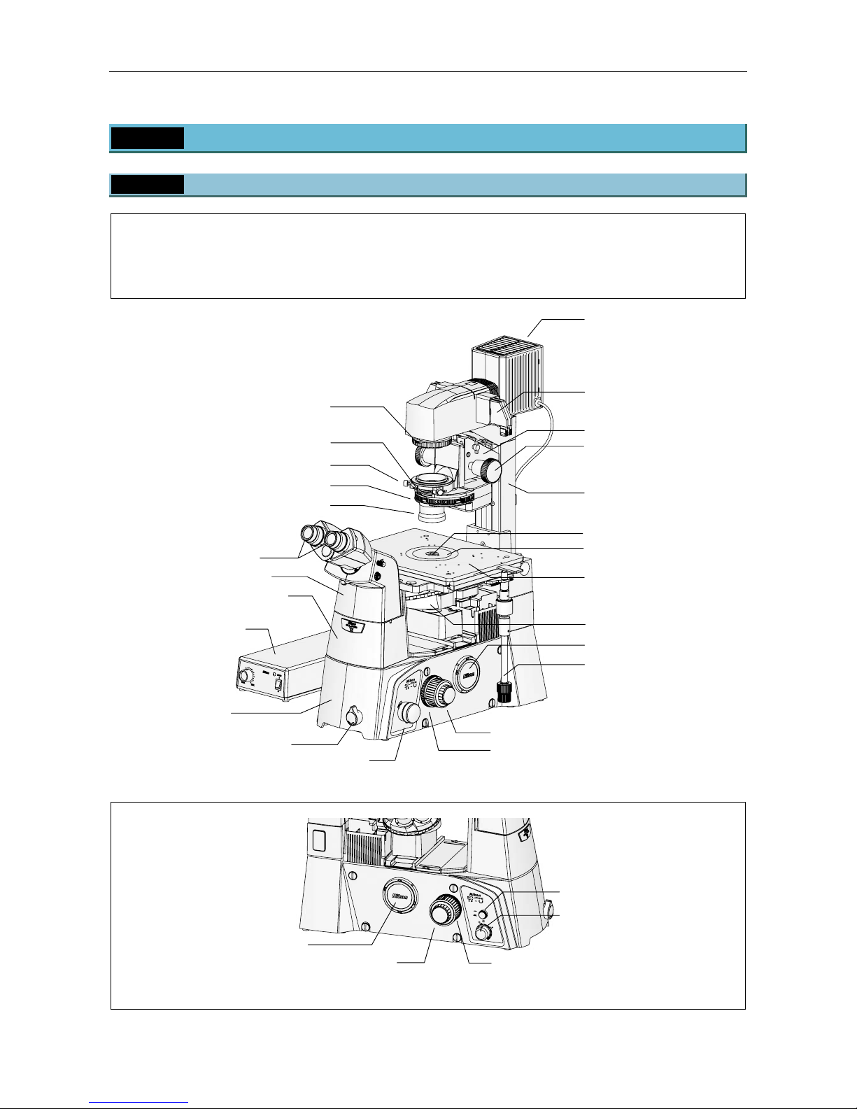
The illustrations below show the Ti-U microscope body with the following accessories:
TI-DH Dia Pillar Illuminator 100W, TI-C Condenser Turret, D-LH/LC Precentered Lamphouse LC, 12V
100W halogen lamp, TI-PS100W Power Supply, TI-SR Rectangular Mechanical Stage, TI-T-B Eyepiece
Base Unit, TI-TD Eyepiece Tube B, CFI 10x eyepieces, TI-ND6 Sextuple DIC Nosepiece, objectives, etc.
PORT
B
Figure 1-1 Ti-U
ON
OFF
6V30W
MAX.
12V100W
Figure 1-2 Ti-U (Left View)
* Attach a protective cap on the side port when the side port is not in use.
Dia illumination brightness
control knob
Dia illumination ON/OFF switch
Left side port*
Focus knob
(Coarse/Fine)
Torque adjustment ring
for coarse focus knob
Lamphouse for dia
illumination
(Fig.: D-LH/LC)
Filter sliders
(both sides, 4 total)
Dia pillar illuminator
(Fig
.: TI-DH)
Condenser mount
Stage (Fig.: TI-SR)
Nosepiece (Fig.: TI-ND6)
Stage knob
Right side port
Focus knob (Coarse/Fine)
Coarse focus stopper ring
Intermediate magnification
selector knob
(1.5x <
---
> 1x)
Microscope base
(Fig.: Ti-U)
Power supply device
(Fig.: TI-PS100W)
Eyepiece base unit (Fig.: TI-T-B)
Eyepiece tube (Fig.: TI-TD)
Eyepieces (both sides)
Field diaphragm knob
Condenser lens
Condenser turret (Fig.: TI-C)
Condenser centering knob (both sides)
Aperture diaphragm open/close leve
r
Condenser focus knobs
(both sides)
Objectives
Stage ring (concentric ring)
Optical path
selector knob
Page 15
Chapter 1 Part Names
1.1 Microscope Configuration
13
1.1.2 Ti-S, Ti-S/L100
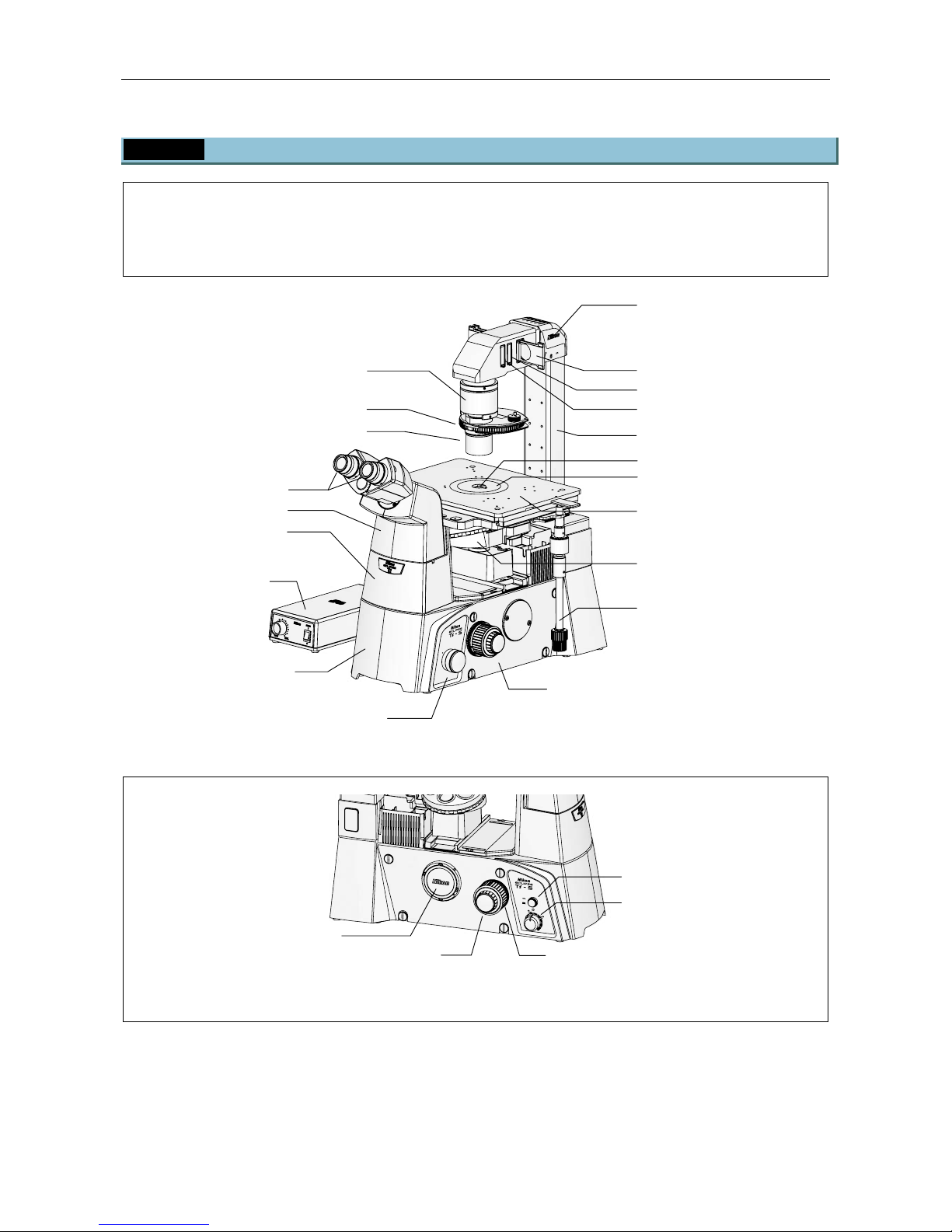
The illustrations below show the Ti-S microscope body with the following accessories:
TI-DS Dia Pillar Illuminator 30W, ELWD-S Condenser, TE-PS30 30W Power Supply, TI-SR Rectangular
Mechanical Stage, TI-T-B Eyepiece Base Unit, TI-TS Eyepiece Tube B, CFI 10x eyepieces, TI-N6
Sextuple Nosepiece, objectives, etc.
PORT
SIDE
EYE
EN
TI
-
DS 30W
6V 30W
HALOGEN
Figure 1-3 Ti-S
ON
OFF
6V30W
MAX.
12V100W
Figure 1-4 Ti-S (Left View)
* Attach a protective cap on the side port when the side port is not in use.
Lamphouse
Dia pillar illuminator (Fig.: TI-DS)
Filter sliders
Stage (Fig.: TI-SR)
Nosepiece (Fig.: TI-N6)
Stage knob
Optical path selector knob
Main body (Fig.: Ti-S)
Power supply device
(Fig.: TI-PS30W)
Eyepiece base unit
(Fig.: TI-T-B)
Eyepiece tube (Fig.: TI-TS)
Eyepieces (both sides)
Condenser lens
Condenser turret (Fig.: ELWD-S)
Condenser holde
r
Objectives
Stage ring (concentric ring)
Field diaphragm slider
Focus knob (Coarse/Fine)
Dia illumination brightness
control knob
Dia illumination ON/OFF switch
Left side port*
Torque adjustment ring
for coarse focus knob
Focus knob
(Coarse/Fine)
Dustproof slider
Page 16
Chapter 1 Part Names
1.2 Microscope Base
14
1.2 Microscope Base
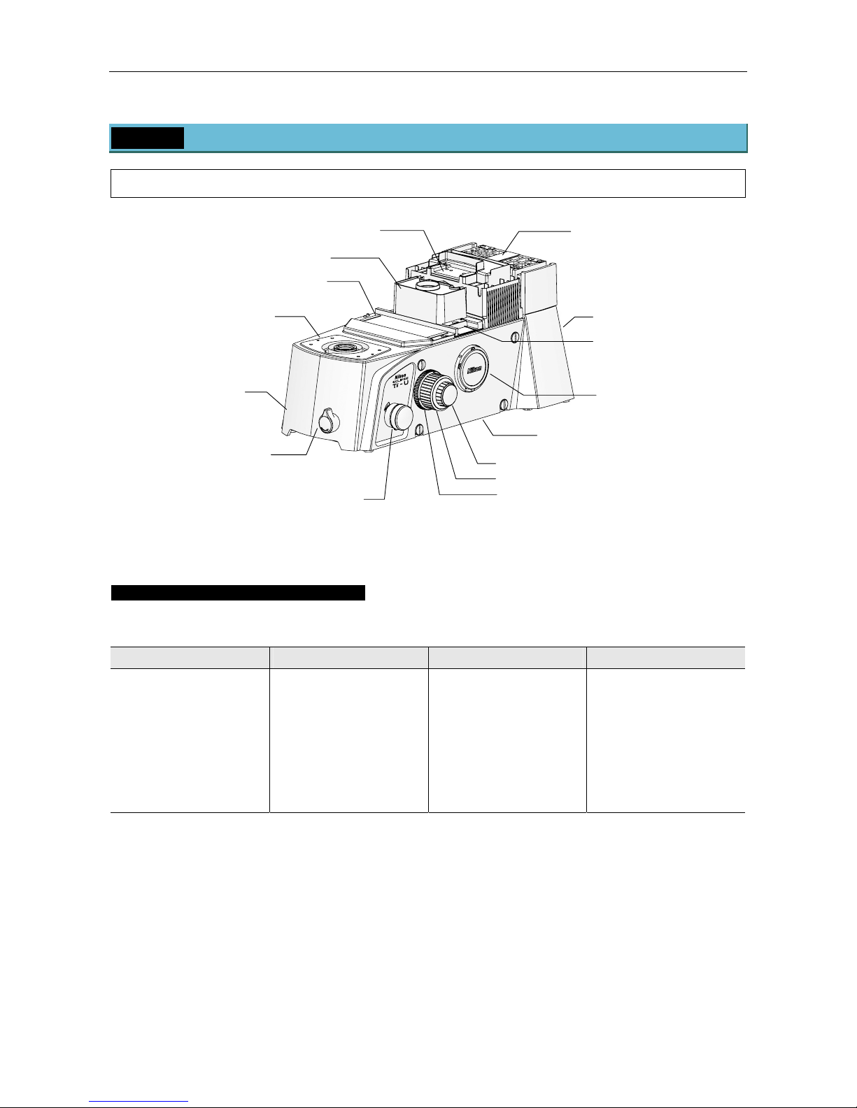
To keep out extraneous light and dust, be sure to attach the provided caps to all ports not in use.
PORT
Figure 1-5 Microscope Base
Optical Path Selector Knob Operation
Ti series microscopes have multiple output ports. Use the optical path selector knob to select the output
port for the microscope image.
Ti-U Ti-U/B Ti-S Ti-S/L100
EYE Visual observation
100%
R Right side port
100%
AUX Prism attachment
position
L Left side port 100%
EYE Visual observation
100%
R Right side 100%
B Bottom port 100%
L Left side 100%
EYE Visual 100%
SIDE Visual observation
20%, Left side port
80%
EYE Visual observation
100%
SIDE Left side port 100%
Dia pillar illuminator mount
(A carrying handle is
attached for transportation)
Connector panel (rear)
Right side port
(Ti-U and Ti-U/B only)
Fine focus knob
Bottom port
(on the bottom, Ti-U/B only)
Intermediate magnification
selector knob
(1.5x <
---
> 1x)
(Ti-U and Ti-U/B only)
Ti-U/B has a front optical
path selector knob fo
r
the bottom port
Optical path
selector knob
Eyepiece base unit
mount
Nosepiece mount
Cove
r
A
nalyzer slot
A
dummy slider is attached
for trans
p
ortation.
Coarse focus knob
Coarse focus stopper ring
(Ti-U and Ti-U/B only)
Filter turret mount
Page 17
Chapter 1 Part Names
1.2 Microscope Base
15
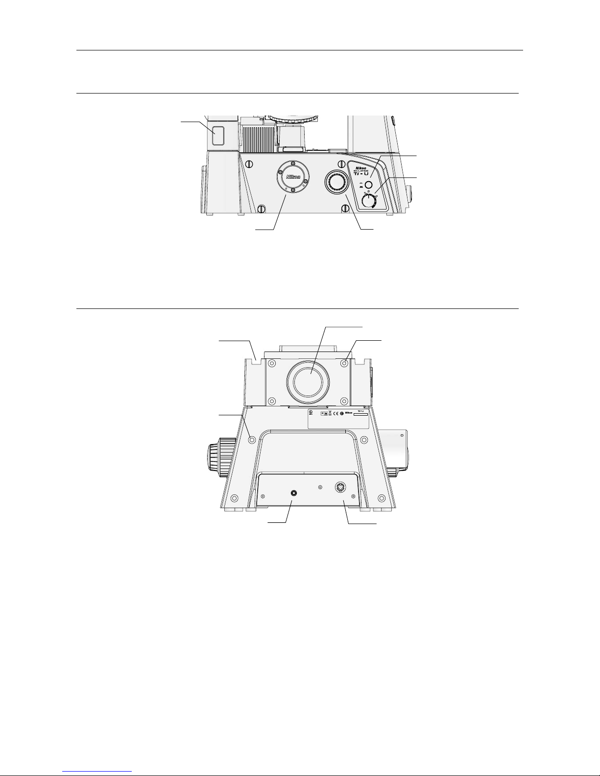
Left View
6V30W
MAX.MIN.
12V100W
ON
OFF
Figure 1-6 Microscope Base (Left View)
Rear View (Connector Panel)
INTERLOCK
LAMP CTRL
Gepruftes Medizinprodukt
Approved medical device
Freiwillige Produktprufung
R
5 3 2 0 0 1
This device complies with Part 15 of the FCC Rules.Operation is subject to the
following two conditions:
(1) this device may not cause harmful interference,and
(2)
EQUIPMENT 4N75
MODEL : Ti-U
INSPECTION
TUV
Rheinland
Product Safety
JAPAN
this device must accept any interference received, including interference
that may cause undesired operation.
This Class A digital apparatus complies with Canadian ICES-003.
Cet appareil numØrique de la classe A est conforme la norme NMB-003 du Canada.
Figure 1-7 Microscope Base (Rear View)
Epi-fl illumination field
diaphragm slide
r
mount
Fine focus knob,
Coarse focus knob,
Torque adjustment ring for coarse focus knob
Left side port
Dia illumination lamp
ON/OFF switch
Dia illumination
brightness control knob
Epi-fl illumination mount
LAMP CTRL connector
(for dia illumination power supply)
INTERLOCK connecto
r
(for external laser controller)
(Ti-U and Ti-U/B only)
Hub Controller B attachment
screw holes (x4)
Power cable groove
(both sides)
Epi-fl illumination attachment
screw holes (x4)
Page 18

Chapter 1 Part Names
1.3 Eyepiece Base Unit, Eyepiece Tube, and Eyepieces
16
1.3 Eyepiece Base Unit, Eyepiece Tube, and Eyepieces
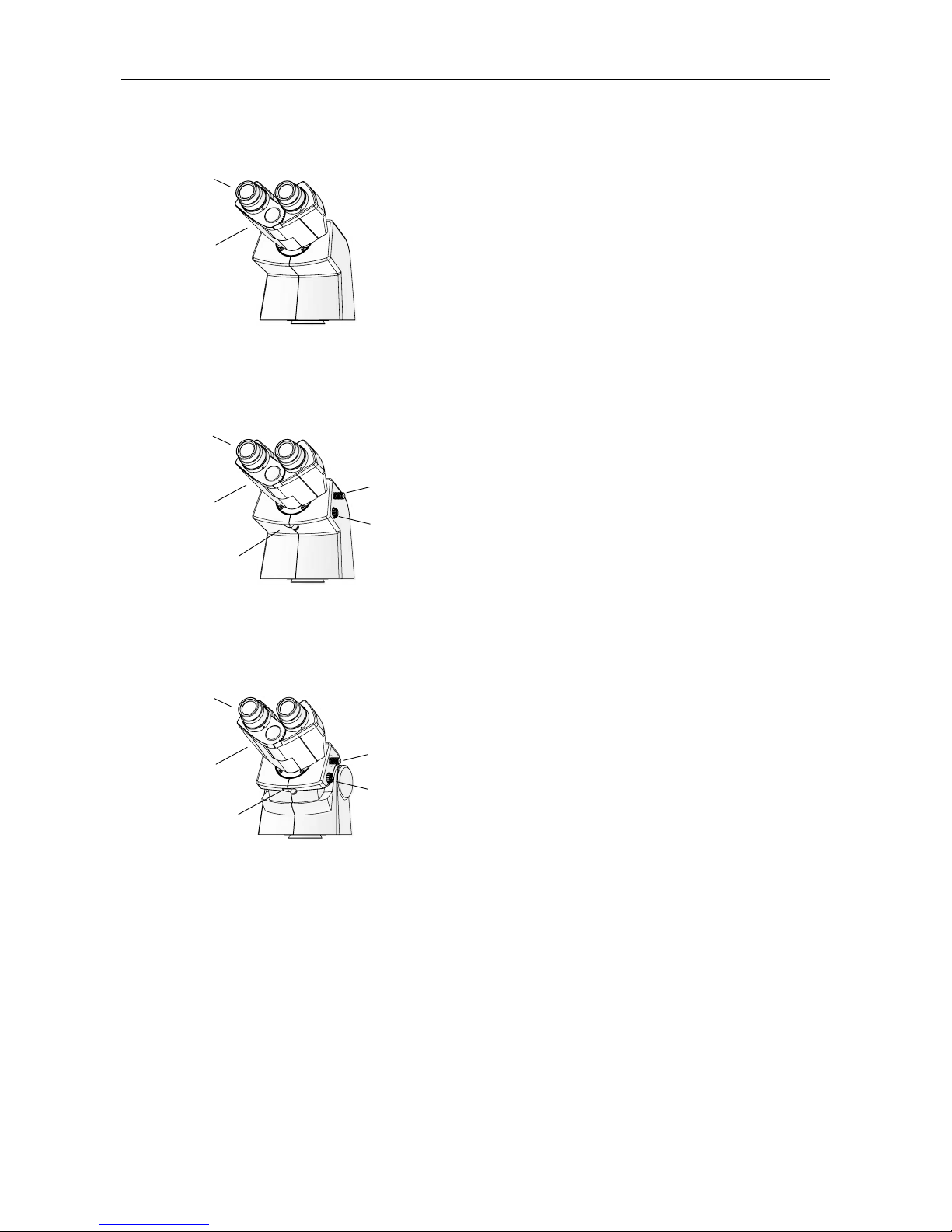
The following eyepiece base units, eyepiece tubes, and eyepieces can be mounted on the observation port
of the microscope.
TI-T-B Eyepiece Base Unit
Figure 1-8 TI-T-B Eyepiece Base Unit
Basic eyepiece base unit.
A
circular dovetail joint is provided on the top surface
for eyepiece tube attachment. Attach an eyepiece
tube for visual observation.
If you will not be performing visual observation, you
do not need to attach an eyepiece tube. In this case,
be sure to attach a cover onto the circular dovetail
joint.
TI-T-BS Eyepiece Base Unit (with Side Port)
S
I
D
E
E
Y
E
Figure 1-9 TI-T-BS Eyepiece Base Unit
Eyepiece base unit with a camera port.
Rotate the optical path selector knob on the right to
distribute the light between the eyepiece tube and
the side port.
The side port is equipped with a C-mount adapter for
attaching microscopy cameras.
TI-T-BPH External Phase Contrast Eyepiece Base Unit
S
I
D
E
E
Y
E
Figure 1-10 TI-T-BPH Eyepiece Base Unit
Eyepiece base unit for external phase contrast
microscopy.
A turret for phase contrast rings is provided on the
front of the eyepiece base unit. The turret has three
positions (A, B, and C) that can each hold an
external phase contrast phase plate. The focus can
be adjusted independently for each position. The
turret has screws on its sides for centering the phase
contrast rings, and clamp screw on its back for fixing
the adjusted position.
On the left side, a side port with a C-mount adapter
is provided. On the right side, an optical path
selector knob is provided for light distribution
between the eyepiece tube and the side port.
When performing photomicroscopy during external
phase contrast microscopy, use this side port.
Circular dovetail
j
oint
Eyepiece tube
locking screw
Centering screws
(2 positions)
Optical path
selector knob
Focusing screws
Circular dovetail
j
oint
Eyepiece tube
locking screw
Circular
dovetail joint
Eyepiece tube
locking screw
Side port
(with C-mount adapter)
Optical path
selector knob
Stage mount
Eyepiece tube
mount
Microscope moun
t
(bottom)
Stage mount
Eyepiece tube
mount
Microscope mount
(bottom)
Stage mount
Eyepiece tube mount
Side port
(with C-mount adapter)
Centering clamp
screw
(back, 2 positions)
Microscope mount
(bottom)
Turret
Page 19
Chapter 1 Part Names
1.3 Eyepiece Base Unit, Eyepiece Tube, and Eyepieces
17
TI-TS Eyepiece Tube B
Figure 1-11 TI-TS Eyepiece Tube B
Simple and basic eyepiece tube.
TI-TD Eyepiece Tube B
B
Figure 1-12 TI-TD Eyepiece Tube B
Eyepiece tube with a manual shutter and a Bertrand
lens.
The shutter can be closed to cut off the optical path
to the eyepieces, for example when observing with a
camera.
The Bertrand lens can be moved into the optical
path for observation of the objective pupil plane.
TI-TERG Ergonomic Eyepiece Tube
B
Figure 1-13 TI-TERG Ergonomic Eyepiece Tube
Eyepiece tube with an adjustable binocular that can
be inclined to fit the user.
Like TI-TD Eyepiece Tube B, this eyepiece tube is
equipped with a Bertrand lens. The optical path to
the eyepieces can be cut off, for example when
observing with a camera. The Bertrand lens can be
moved into the optical path for observation of the
objective pupil plane.
Eyepieces
(both sides,
sold separately)
Binocular part
Eyepieces
(both sides,
sold separately)
Binocular part
Shutter
operation lever
Bertrand lens
focusing knob
Bertrand lens
in/out leve
r
Eyepieces
(both sides, sold
separately)
Binocular part
Shutter
operation lever
Bertrand lens
focusing knob
Bertrand lens
in/out leve
r
Page 20
Chapter 1 Part Names
1.4 Stage
18
1.4 Stage
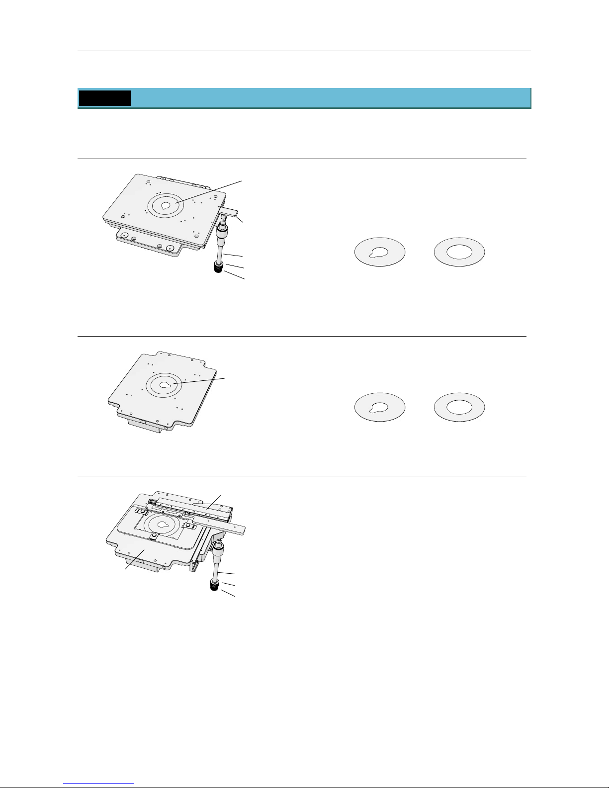
The following stages can be attached to the product.
TI-SR Rectangular Mechanical Stage
Figure 1-14 Rectangular Mechanical Stage
The specimen can be moved in the X and Y
directions by operating the stage knob.
The rectangular mechanical stage comes with two
stage clips for culture vessels, and the following two
concentric rings.
25 mm bore
(with oiling notch)
40 mm bore
TI-SP Plain Stage
Figure 1-15 Plain Stage
Simple, fixed stage for easy operation of specimens.
The plain stage comes with the following two
concentric rings.
25 mm bore
(with oiling notch)
40 mm bore
TI-SAM Attachable Mechanical Stage
Figure 1-16 Attachable Mechanical Stage
(on Plain Stage)
This stage is attached to the plain stage when using
specimen holders. The specimen can be moved in
the X and Y directions by operating the stage knob.
Various specimen holders can be used by attaching
the following adapters to the provided microplate.
• MA60 microplate holder
• MA60 Petri dish holder
• MA glass slide holder
• 35 Petri dish holder
Stage knob
・Y-axis direction
・X-axis direction
Plain stage
A
ttachable mechanical stage
Stage ring
(concentric ring)
Rack
Stage knob
・Y-axis direction
・X-axis direction
Stage ring
(concentric ring)
Page 21
Chapter 1 Part Names
1.5 Dia Pillar Illuminator
19
1.5 Dia Pillar Illuminator
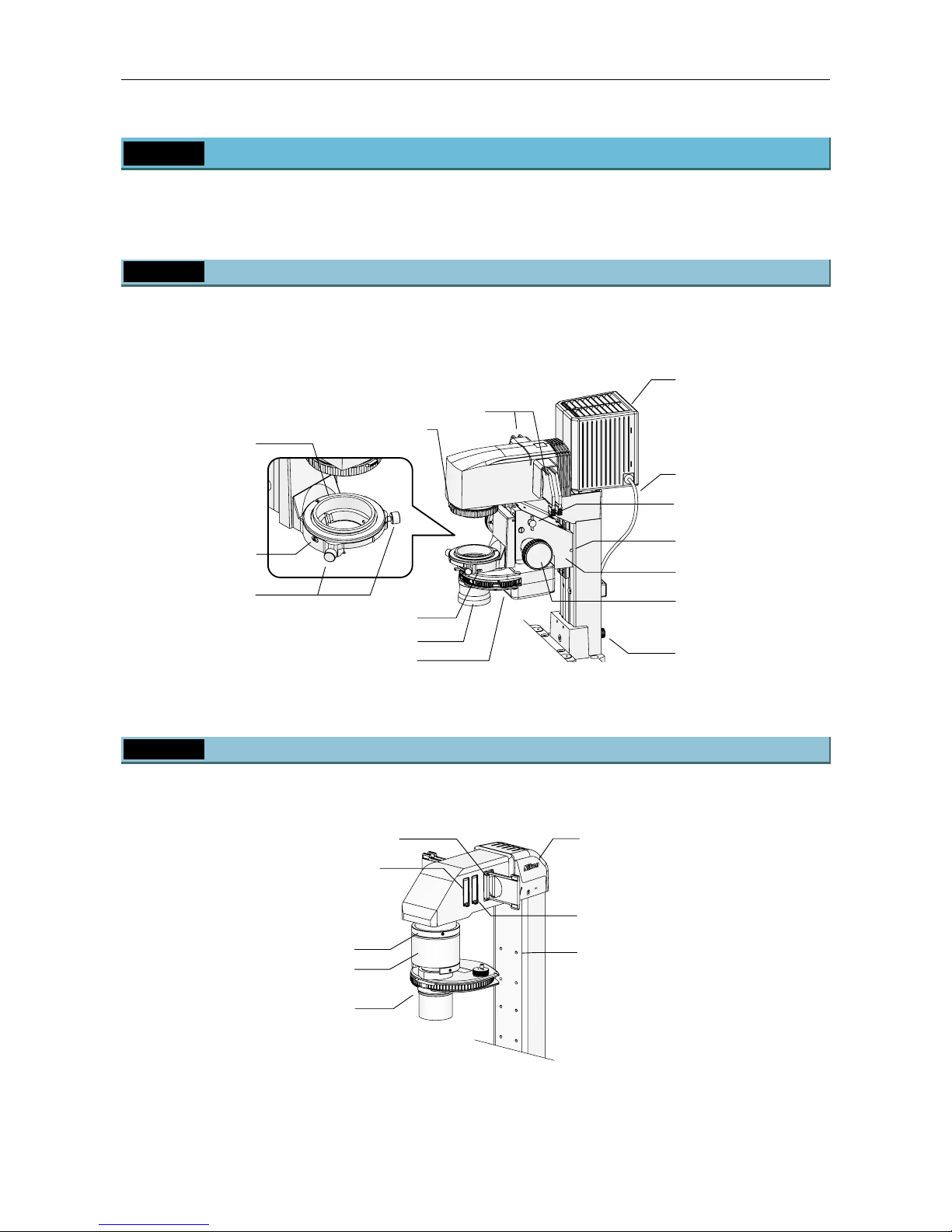
Ti series microscopes can be used with the following two types of dia pillar illuminators. The two dia pillar
illuminators differ in lamp rating (12V 100W or 6V 30W) and support different microscopy methods. Select
the dia pillar illuminator to suit your application.
1.5.1 TI-DH Dia Pillar Illuminator 100W
The TI-DH Dia Pillar Illuminator 100W is used with a separate lamphouse and condenser.
The following illustration shows the TI-DH Dia Pillar Illuminator 100W with the D-LH/LC Precentered
Lamphouse and the TI-C Condenser Turret (System Condenser) attached.
Figure 1-17 TI-DH Dia Pillar Illuminator 100W
(with Lamphouse and System Condenser)
1.5.2 TI-DS Dia Pillar Illuminator 30W
The TI-DS Dia Pillar Illuminator 30W has a built-in lamphouse, but requires a separate condenser.
The following illustration shows the TI-DS Dia Pillar Illuminator 30W with the ELWD-S Condenser.
EN
TI
-
DS 30W
6V
30W
HALOGEN
Figure 1-18 TI-DS Dia Pillar Illuminator 30W
(with ELWD-S Condenser)
D-LH/LC Precentered
Lamphouse LC
Requires TI-PS100W
power supply
Lamp cable
Condenser mount
(rotatable)
Condenser mount
rotation clamp scre
w
Condenser centering
knob
Condenser lens
TI-C System Condenser Turret
Condenser clamp scre
w
Field diaphragm knob
Pillar locking clamp knob
Filter sliders (both sides, 4 total)
Condenser refocusing
clamp
Condenser focus knobs
(both sides)
Condenser holder
(detachable)
Condenser holder clamp
screw
Field diaphragm slider
Lamphouse (6V 30W lamp, sold separately)
(Requires TE-PS30W or TE-PSE30 power
supply.)
Filter sliders (max. 3)
Dustproof slide
r
Device attachment screw holes (M4, x8)
Condenser mount
Condenser holde
r
ELWD-S Condense
r
Page 22
Chapter 1 Part Names
1.6 Condenser
20
1.6 Condenser
1.6.1 TI-C Condenser Turret (System Condenser)
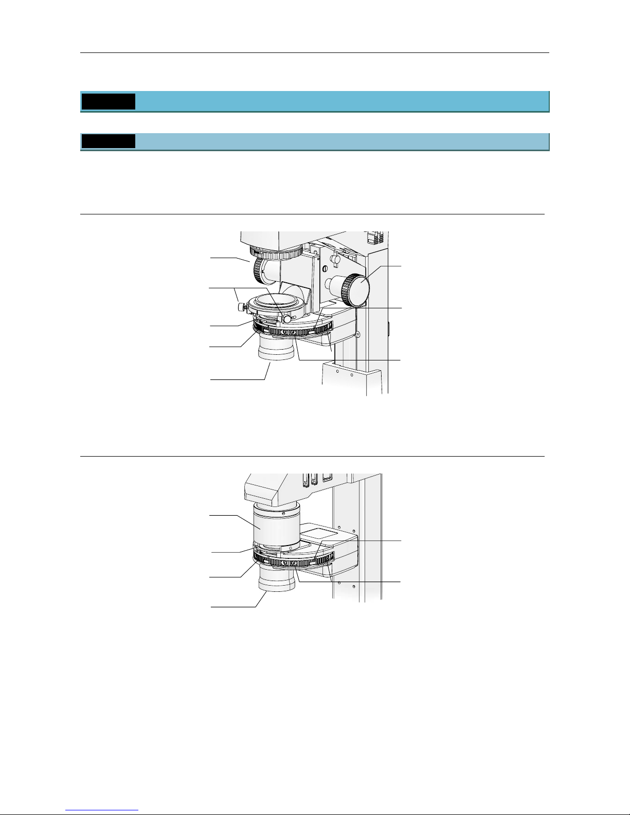
The TI-C Condenser Turret allows you to attach various optical elements to a turret and select them as
necessary for different microscopy methods. This type of condenser is referred to as a “system condenser”.
System Condenser (Mounted on TI-DH Dia Pillar Illuminator 100W)
Figure 1-19 TI-C Condenser Turret
(mounted on TI-DH Dia Pillar Illuminator 100W)
System Condenser (Mounted on TI-DS Dia Pillar Illuminator 30W)
Figure 1-20 TI-C Condenser Turret
(mounted on TI-DS Dia Pillar Illuminator 30W)
* The system condenser can be mounted on the TI-DS Dia Pillar Illuminator 30W for HMC observation only.
Condenser focus knob
Condenser focus knob
Condenser centering knob
Condenser lens
(4 types: ELWD, LWD,
HMC, and CLWD)
Condenser cassette clamp screws
(
both sides of cassette)
Condenser turret
Condenser cassettes
(Ph condenser cassettes have
phase contrast ring centering
screws on the sides.)
Aperture diaphragm
open/close leve
r
Condenser holde
r
Condenser lens
(for HMC only)
Aperture diaphragm
o
p
en/close leve
r
Condenser cassette clamp screws
(both sides of cassette)
Condenser turret
Condenser cassettes
Page 23
Chapter 1 Part Names
1.6 Condenser
21
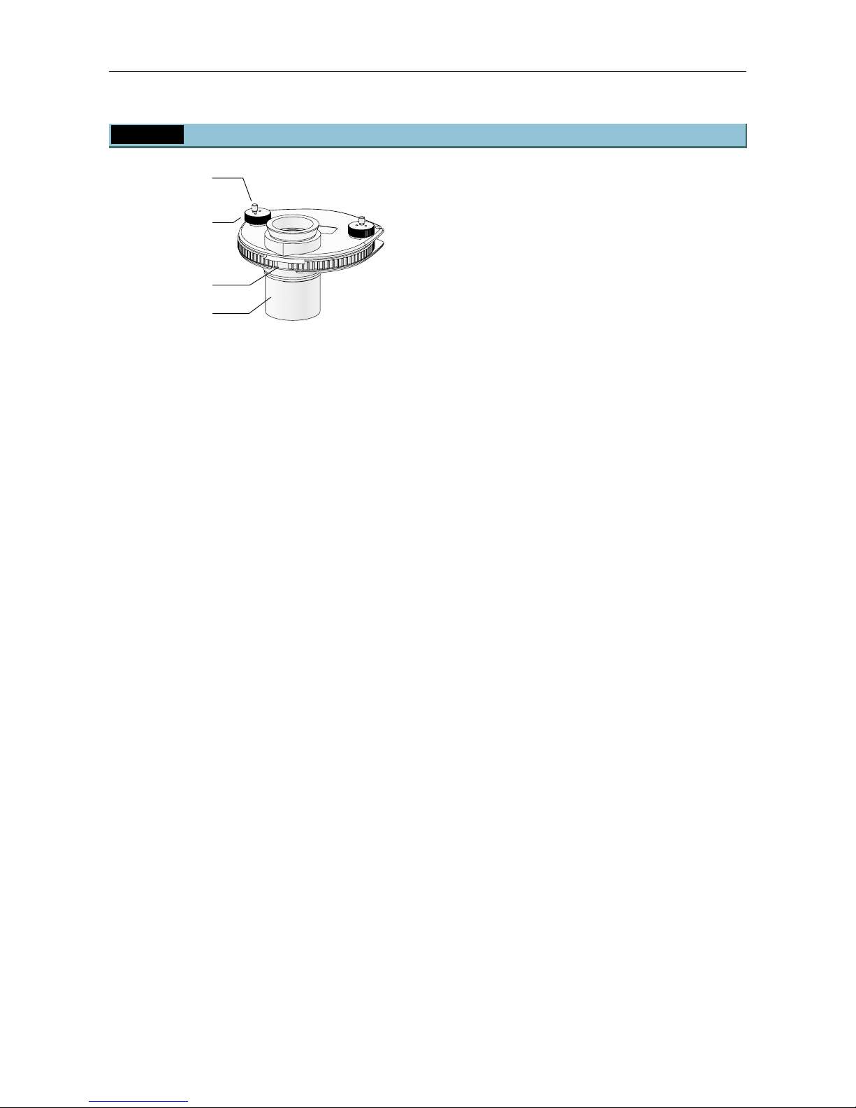
1.6.2 ELWD-S Condenser
Figure 1-21 ELWD-S Condenser
The ELWD-S Condenser supports bright-field
microscopy and phase contrast microscopy. It can
be used with both 100W and 30W dia pillar
illuminators.
Condenser lens
Turret
Centering knob
Clamp screws
(both sides)
Condense
r
Centering knobs
(
both sides
)
Page 24
Chapter 1 Part Names
1.7 Power Supply
22
1.7 Power Supply
1.7.1 TI-PS100W Power Supply
Warning
The bottom of the power supply device becomes hot during use. Do not block the air vents on
the side of the product.
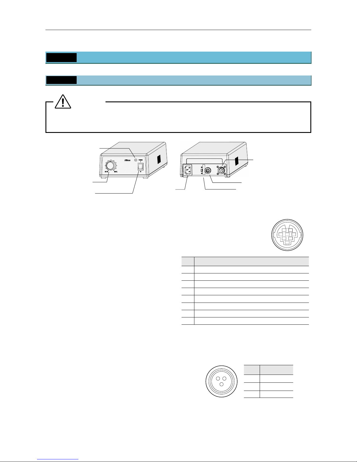
Figure 1-22 TI-PS100W Power Supply
POWER switch
This is the power switch for the power supply. Press
the “I” side of the switch to turn on the power supply
and output DC power from the 12VDC output on the
rear. Press the “O” side of the switch to turn off the
power supply.
POWER indicator
Lit when the power supply is on.
Brightness control knob
When the EXTERNAL switch is turned off, the knob
controls the brightness of the lamp by adjusting the
voltage supplied from the 12VDC output connector.
AC inlet
This is the connector for connecting the power
supply device to a wall outlet. Be sure to use the
specified power cord for the connection.
EXTERNAL (external control) ON/OFF switch
Turn this switch on to use the brightness control
knob on the microscope for output voltage control.
When this switch is turned off, the brightness control
knob on the front of the power supply becomes
enabled, and the brightness control knob on the
microscope becomes disabled.
EXTERNAL (external control signal input)
connector
Connect the control cable to this
connector and the LAMP CTRL
connector on the rear of the
microscope.
1
2
6
8
7
3
45
Pin Signal
1
External resistor terminal for output voltage adjustment
2
External resistor terminal for output voltage adjustment
3
Output voltage ON/OFF switch (input)
4
GND (0V)
5
External voltage input for output voltage adjustment
6
EXTERNAL switch on/off detect signal (output)
7
GND (0V)
8
Output voltage monitor terminal (output)
Connector: HR12-10R-8SC by Hirose Electric Co., Ltd.
12VDC output connector
This connector supplies power to the 12V 100W
halogen lamp. Connect the lamp cable for the pillar
illuminator.
Pin Signal
1
Output +
2
Output -
12
3
3
Not used
Connector: SRCN2A13-3S by Japan Aviation Electronics Industry, Ltd.
POWER switch
POWER indicato
r
Brightness
control knob
AC inlet
12VDC output
connecto
r
EXTERNAL connector
EXTERNAL ON/OFF switch
Page 25
Chapter 1 Part Names
1.7 Power Supply
23
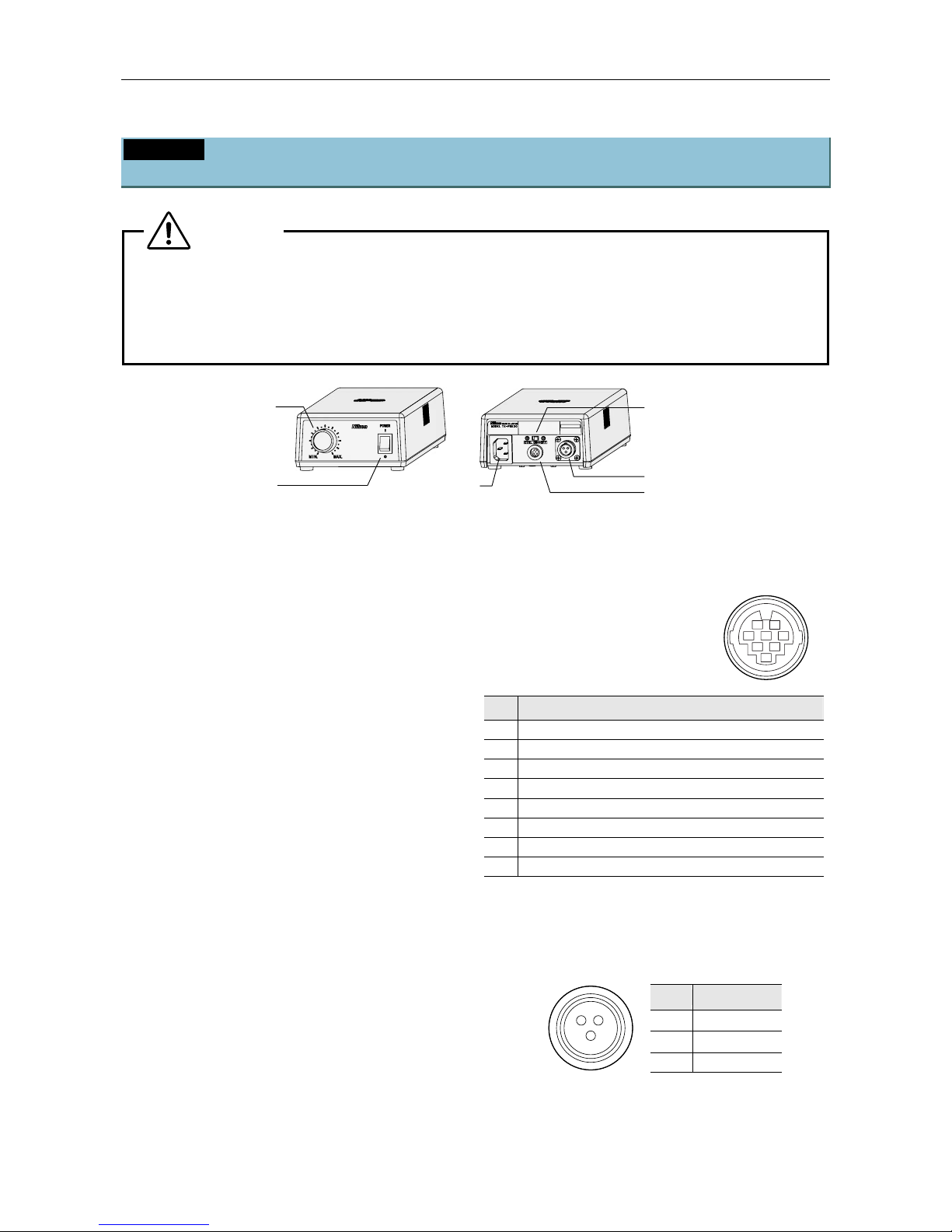
1.7.2 TE-PS30W Power Supply A (for 100-120V)
TE-PSE30 Power Supply A (for 220-240V)
Warning
• Before turning on the power supply, check that the input voltage indicator matches the
power voltage in your area. If the voltages do not match, do not turn on the product, and
contact Nikon. Use of the product under a wrong voltage may result in malfunction or fire.
• The bottom of the power supply device becomes hot during use. Do not block the air vents
on the side of the product.
Figure 1-23 TE-PS30W, TE-PSE30 Power Supply A
POWER switch/indicator
This is the power switch for the power supply. Press
the “I” side of the switch to turn on the power supply
and output DC power from the 6VDC output on the
rear. The switch is lit when the power supply is on.
Press the “O” side of the switch to turn off the power
supply.
Brightness control knob
When the CTRL switch is turned off, this knob
controls the brightness of the lamp by adjusting the
voltage output from the 6VDC output connector.
AC inlet
This is the connector for connecting the power
supply device to a wall outlet. Be sure to use the
specified power cord for the connection.
CTRL (external control) ON/OFF switch
Turn this switch on to use the brightness control
knob on the microscope for output voltage control.
When this switch is turned off, the brightness control
knob on the front of the power supply becomes
enabled, and the brightness control knob on the
microscope becomes disabled.
CTRL (external control signal input) connector
Connect the control cable to this
connector and the LAMP CTRL
connector on the rear of the
microscope.
1
2
6
8
7
3
45
Pin Signal
1
External resistor terminal for output voltage adjustment
2
External resistor terminal for output voltage adjustment
3
Output voltage ON/OFF switch (input)
4
GND (0V)
5
Not used
6
Not used
7
Not used
8
Not used
Connector: HR12-10R-8SC by Hirose Electric Co., Ltd.
6VDC output connector
This connector supplies power to the 6V 30W
halogen lamp. Connect the lamp cable for the pillar
illuminator.
Pin Signal
1
Output -
2
Not used
12
3
3
Output +
Connector: SRCN2A13-3S by Japan Aviation Electronics Industry, Ltd.
Brightness control
knob
AC inlet
6VDC output connector
CTRL connector
CTRL ON/OFF switch
POWER
switch/indicato
r
 Loading...