

Page 1

M248 E 06.2.NF.3
Stereoscopic Zoom Microscope
SMZ1000 / SMZ800
Instructions
Page 2

Page 3
Thank you for purchasing the Nikon product.
This instruction manual is written for the users of Nikon
Stereoscopic Zoom Microscopes.
To ensure correct usage, read this manual carefully before
operating the instrument.
• It is prohibited to reproduce or transmit this manual in part or
whole without Nikon’s expressed permission.
• The contents of this manual are subject to change without notice.
• Although every effort has been made to ensure the accuracy of
this manual, if you note any points that are unclear or incorrect,
contact your nearest Nikon representative.
• Some of the products described in this manual may not be
included in the set you have purchased.
• If the equipment is used in a manner not specified by the
manufacturer, the protection provided by the equipment may be
impaired.
Warning/Caution Symbols Used in This Manual
Though Nikon products are designed to provide you with the
utmost safety during use, incorrect usage or disregard of the
instructions may cause personal injury or property damage. For
your own safety, read the instruction manual carefully and
thoroughly before using the product. Do not discard this manual.
Always keep it near the product for easy reference.
Inside this instruction manual, safety instructions are indicated
with the symbols shown below. Be sure to follow the instructions
marked with these symbols for your safety.
Symbol Meaning
WARNING
CAUTION
Disregarding instructions marked with this
symbol may lead to death or serious injury.
Disregarding instructions marked with this
symbol may lead to injury or property
damage.
1
Page 4

Be sure to always follow these guidelines.
WARNING
1. Intended use of this product
This product is intended only for microscopy. Do not
use it for any other purpose.
2. Do not disassemble
Disassembly may result in damage to the instrument.
Never disassemble any part except as described in this
operation manual. Contact your Nikon representative if
you notice any malfunction of this instrument.
3. Check the input voltage
When using an illuminator, check that the input voltage
displayed on the power supply of the illuminator
matches the operating voltage. Contact your Nikon
representative if the displayed voltage does not match the
operating voltage. Use of an improperly matched
illuminator may result in damage to equipment.
4. Power cord
Always turn the power switch off and unplug the power
cord when replacing the lamp of an illuminator as failure
to do so may result in electric shock or equipment
damage.
5. Heat from the light source
When using an illuminator, do not place cloth or paper or
highly flammable materials, such as gasoline, benzene,
thinner or alcohol, near the lamp as there is a danger of
fire.
• Always use lamps that are of the specified rating only.
For the lamp rating, please refer to the operation
manual.
• Always turn the power switch off and unplug the
power cord when replacing the lamp of a illuminator
as failure to do so may result in electric shock or
equipment damage.
2
Page 5
CAUTION
1. Caution when replacing lamps
2. Check the light source
The lamp and the surrounding area become very hot
during and immediately after using the illuminator. Be
careful not to burn yourself. In addition, when replacing
a lamp be sure the lamp has cooled sufficiently.
Always use lamps that are of the specified rating only.
Use of a lamp having a different specification may result
in damage to equipment. For the lamp rating, please
refer to the operation manual.
3
Page 6

1. Installation location
Note the following points when installing the stereoscopic
microscope.
• Install the microscope in a location with the temperature between
0° and 40°C, and humidity of less than 80%. If installed in a hot
and humid location, mold may form on the lenses or condensation
may occur inside, resulting in reduced performance or damage to
the microscope.
• Do not install the microscope in a location subject to direct
sunlight.
• Install the microscope in a location that is not subject to vibration.
• Install the microscope in a location that is free from dust and dirt.
2. Handle the microscope carefully
The stereoscopic microscope is a precision optical instrument.
Handle it carefully and do not subject it to impact. Shock from
impact during transportation or operation as well as forcible
operations may cause damage to the instrument.
3. Cleaning the lenses
Do not let dust, fingerprints, etc. to get on the lenses. Dirt on the
lenses will adversely affect the view of the image. If any lenses
become dirty, clean them as described below.
• Use an air blower to blow dust away. If this does not suffice, brush
away the dust with a soft brush or gently wipe it away with a piece
of gauze.
• Only if the lenses become dirty with fingerprints or grease stains,
slightly dampen a piece of soft, clean cotton cloth with absolute
alcohol (ethyl alcohol or methyl alcohol) and gently wipe away the
dirt. Do not use the same part of the cloth more than once.
• Since absolute alcohol is highly flammable, be careful in handling
it so that it does not ignite.
• Observe the manufacturer’s handling instructions when handling
absolute alcohol.
4
Page 7

Be sure to always follow these guidelines.
4. Cleaning painted or plastic parts
Use of silicon cloth is recommended when cleaning painted parts,
plastic parts and printed parts. If such a part becomes excessively
dirty, wipe it gently with gauze dampened in a mild detergent
solution. Do not use organic solvents (such as alcohol, ether, or paint
thinner) as this may result in deformation of the part or remove of
lettering.
5. Storage
Store the microscope in a location with low humidity where mold is
unlikely to form. Do not store the microscope in a location subject
to direct sunlight or high temperature and humidity. During storage,
place a plastic cover over the equipment to prevent dust
accumulation.
6. Regular inspections
Regular inspections are recommended in order to maintain peak
performance. Please consult your Nikon representative for details
about regular inspections.
5
Page 8

Contents
Warning/Caution Symbols Used in This Manual ...........................1
Be sure to always follow these guidelines. ....................................2
WARNING ..........................................................................................2
CAUTION ........................................................................................... 3
I Nomenclature ...................................................................................8
II Assembly .........................................................................................12
III Usage ................................................................................................ 15
1 Preparations For Observation ......................................................15
1. Adjust the torque of the focus knob.......................................15
2. Adjust the interpupillary distance. ......................................... 15
3. Adjust the diopter. ................................................................. 16
2 Focusing ...................................................................................... 16
1. Check the working distance................................................... 16
2. Focus on the sample. ............................................................. 16
3 Zoom ........................................................................................... 17
1. Change the zooming magnification. ......................................17
4 If You Cannot Focus On The Sample Though The Zooming
Body Is At The Highest Position. ................................................18
IV Using Accessories ........................................................................19
1 Reticles ........................................................................................19
2 Eyepiece Tube ............................................................................. 19
1. P-BTL low eye-level eyepiece tube .......................................19
2. P-BERG tilted eyepiece tube .................................................20
3 P-IER Eyelevel Riser .................................................................. 20
4 Plan 1X ERGO Objective ...........................................................21
5 SM-S4L 4 X 4 Stage L ................................................................22
V Illuminator ....................................................................................... 23
1 Halogen Illuminators ...................................................................23
1. Lamp ......................................................................................24
2. Attaching G-LS to the stand [C-PS & C-PSC] ...................... 25
3. Arm for halogen illuminators ................................................25
4. Power supplies .......................................................................27
6
Page 9

5. Lighting area adjustment [G-LS]........................................... 29
6. Attaching filters [C-DSLS].................................................... 29
2 P-ICI2 Coaxial Episcopic Illuminator .........................................29
VI Photomicrographic and TV-related Accessories ..................32
1. Photomicrographic magnification ......................................... 33
2. Attaching the beam splitter .................................................... 33
3. Photo reticles ......................................................................... 34
4. Photomicrography procedure ................................................ 34
Table 1: Total Magnification and Real Field...................................... 36
Table 2: Observable Sample Heights [mm] .......................................38
7
Page 10
Nomenclature
I
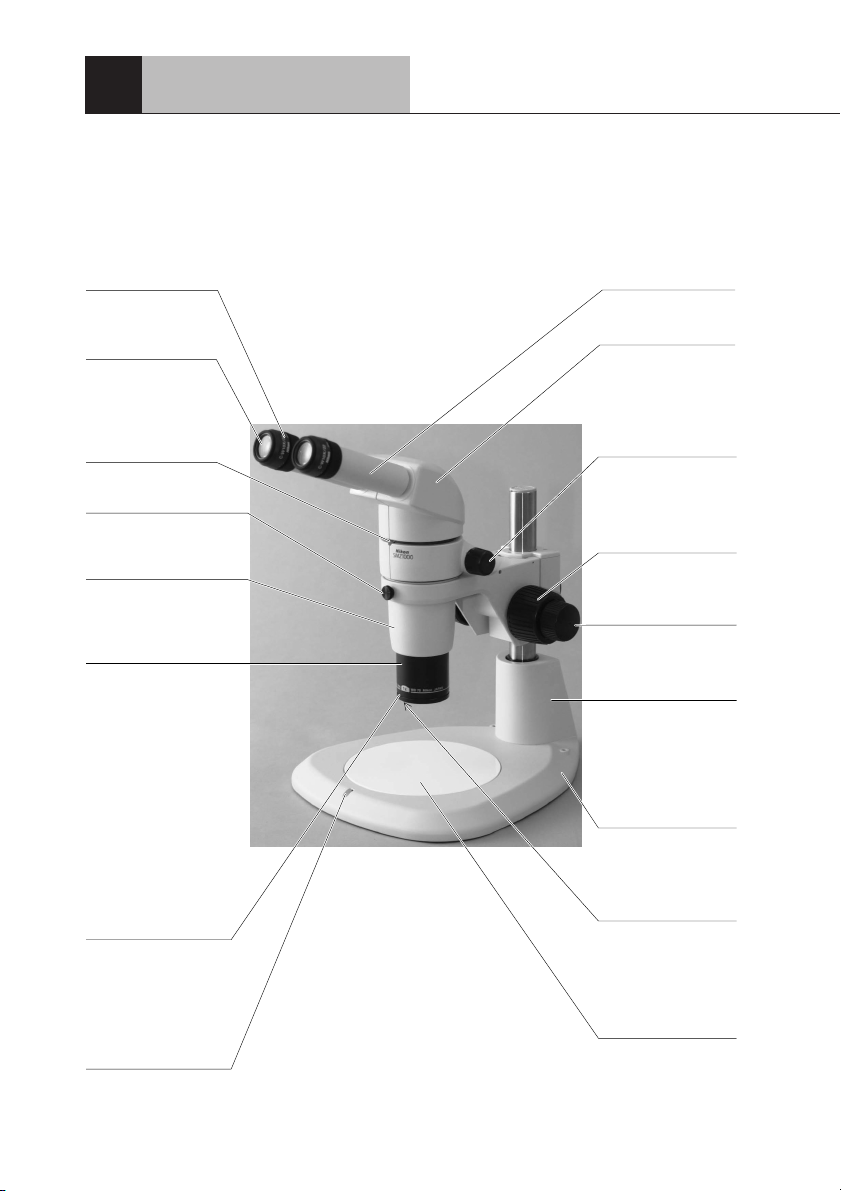
The figures on p.8 & 9 show a SMZ1000 zooming body, with P-BT
binocular eyepiece tube, C-W 10X eyepieces, Plan Apo 1X objective,
C-FMC focusing mount, and C-PS160 plain stand.
Diopter ring
Refer to “Adjust the
diopter” on p.16.
Eyepieces
10X, 15X, 20X and
30X eyepieces are
available.
Eyepiece tube
clamp screw
Zooming body
clamp screw
Fixes the zooming body
to the focusing mount.
Zooming body
Outside diameter of the
part to be mounted the
focusing mount: ø76
Objective
Plan 1X, Achro 0.5X,
Plan 1X ERGO, Plan
Apo 0.5X, Plan Apo 1X,
ED Plan 1.5X and ED
Plan 2X objectives are
available. HR Plan Apo
series objectives for
SMZ1500 can be used
also, but the magnification in this case
becomes 1.25 times the
magnification indicated
on the objective itself.
Refer to Table 1 on p.36.
Groove for mounting
accessories
Holds the Fluorescent
ring illuminator, Fiber
optic ring illuminator
and the like. Outside
diameter: ø60
Stage plate clamp
screw
Fixes the stage plate
to the stand base.
Eyepiece sleeve
P-BT Binocular
eyepiece tube
P-BTL low eye-level
eyepiece tube and PBERG tilted eyepiece
tube are also
available.
Zooming knob
Changes the
magnification of the
sample image. Refer
to “Zoom” on p.17.
Coarse focus knob
Refer to “Focusing”
on p.16.
Fine focus knob
Refer to “Focusing”
on p.16.
Stand
C-PS160 Stand base
Various stands are
available.
Screw for mounting
accessories
Holds the 1/4 lambda
plate and the like.
The screw on the
inside diameter:
M55 × 0.75
Stage plate
The black or the
white side can be
chosen according to
the sample.
8
Page 11
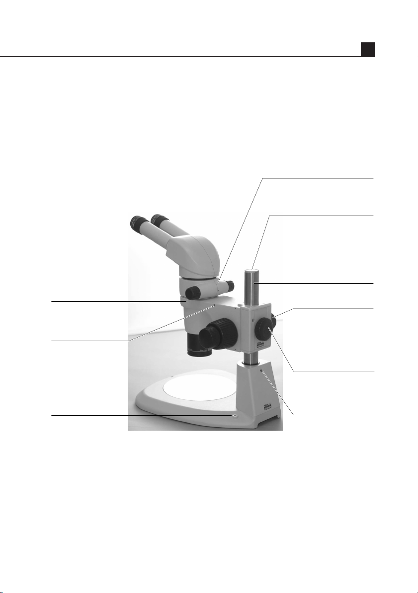
Zooming knob clicks ON/OFF
screw (inside)
Refer to “ON/OFF of the Zooming
Knob Clicks” on p.17.
Clamp tool
Used for the stage plate clamp
screw, eyepiece tube clamp
screw, etc. Same size as the
small hexagonal wrench
supplied with the zooming body.
Stored in the top of the pillar.
Pillar
I
C-FMC Focusing mount
Screw hole for mounting
an Epi-arm for halogen
illuminator
Located on both sides
of the focusing mount.
Holds the G-EIA
flexible arm or Epi-arm.
Screw hole for
mounting accessories
Located on both sides
of the stand base. M5
Torque adjustment ring
(Innermost ring)
Adjusts the torque of the
focus knob. (Refer to
“Adjust the focus knob
torque” on p.15.)
Focusing mount
clamp screw
Fixes the focusing mount
to the pillar.
Pillar clamp screw
(Inside)
9
Page 12
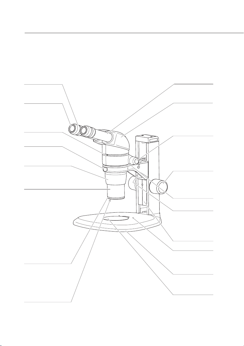
The illustrations on p.10 & 11 show a SMZ800 zooming body, with P-BT
binocular eyepiece tube, C-W 10X eyepieces, Plan 1X objective, and
C-PS plain focusing stand.
Diopter ring
Refer to “Adjust the
diopter” on p.16.
Eyepiece
10X, 15X, 20X and
30X eyepieces are
available.
Eyepiece tube
clamp screw
Zooming body
clamp screw
Fixes the zooming
body to the arm.
Zooming body
Outside diameter of the
part to be mounted on
the arm: ø76
Objective
Plan 1X, Achro 0.5X, Plan
1X ERGO, Plan Apo 0.5X,
Plan Apo 1X, ED Plan
1.5X and ED Plan 2X
objectives are available.
HR Plan Apo series
objectives for SMZ1500
can be used also, but the
magnification in this case
becomes 1.25 times the
magnification indicated on
the objective itself. Refer
to Table 1 on p.36.
Groove for mounting
accessories
Holds the Fluorescent
ring illuminator, Fiber
optic ring illuminator and
the like.
Outside diameter: ø60
Screw for mounting
accessories
Holds the 1/4 lambda
plate and the like.
The screw on the inside
diameter: M55
×
0.75
Eyepiece sleeve
P-BT Binocular
eyepiece tube
P-BTL low eye-level
eyepiece tube and PBERG tilted
eyepiece tube are
also available.
Zooming knob
Changes the
magnification of the
sample image.
Refer to “Zoom” on
p.17.
Focus knob
Refer to “Focusing”
on p.16.
Arm
Arm fixing screw
Holds the arm. The
position of the arm
can be chosen from
either high or low.
Vertical slider
Hole for clip
Holds the clip for
retaining the sample.
C-PS Focusing
stand
Various stands
available.
Stage plate
The black or the
white side can be
chosen according to
the sample.
10
Page 13
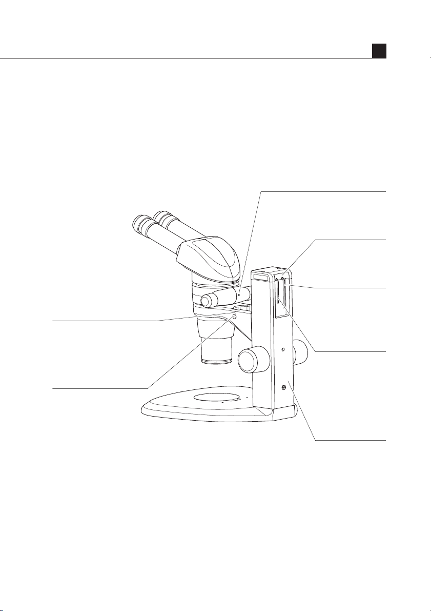
Screw hole for mounting an
Epi-arm for halogen illuminator.
Screw holes are located on
both sides of the arm.
Holds the G-EIA flexible
arm or Epi-arm.
Screw hole for mounting
6V-10W halogen illuminator
Holds the G-LS 6V-10W
halogen illuminator.
Nomenclature
Zooming knob clicks ON/OFF screw
(inside)
Refer to “ON/OFF of the Zooming
Knob Clicks” on p.17.
Hexagonal wrench
hanger
Holds the supplied
hexagonal wrenches.
Hexagonal wrench
(Large)
Supplied with the
focusing stand.
Used for changing
the height of the arm.
Hexagonal wrench
(Small)
Supplied with the
zooming body. Used
for the eyepiece tube
clamp screw and
zooming knob clicks
ON/OFF screw.
I
Pillar
11
Page 14
Assembly
II
• An equipment model name in the bold-faced brackets [ ] indicates
☞
1
2
3
that the following description is exclusively for that model.
[C-PS160]
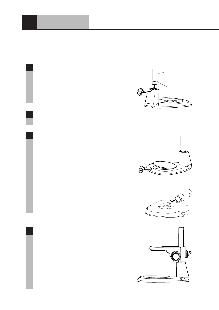
Attach the pillar to the stand.
Insert the pillar straight into the stand with the
groove of the pillar located down as far as the
pillar reaches to the bottom. Clamp the pillar
using the clamp tool.
Place the stand on the level surface.
Mount the stage plate.
[C-PS160]
Fit the stage plate into the stand base. Tighten
the stage plate camp screw using the clamp
tool to fix the stage plate.
Pillar
Groove
12
[C-PS & C-PSC]
Fit the stage plate into the stand base while
pushing it against the rim in the direction
shown by the arrow in the illustration.
[C-PS160]
4
Fix the C-FMC focusing mount to the
pillar.
Face the focusing mount to the front and
tighten the focusing mount clamp screw.
Note) When fixing the focusing mount to the
upper part of the pillar, securely
tighten the clamp screw so as not to
fall the focusing mount.
Page 15
[C-PS & C-PSC]
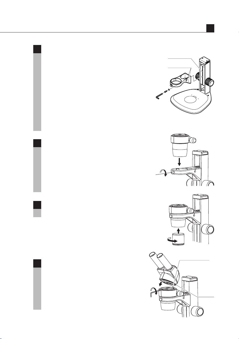
5
The stand arm can be lowered. (If you
do not need to lower the arm, jump to
step 6.)
Use the hexagonal wrench (large - supplied
with the focusing stand) to loosen the arm
fixing screw. Reattach the arm using the
screw hole at the lower side of the vertical
slider. The arm will become 55 mm lower
than its original position. Before tightening
the screw, make sure that the two pins on the
arm fit in the grooves on the vertical slider.
Mount the zooming body.
6
Lightly tighten the zooming body clamp
screw to hold the zooming body on the
focusing mount or arm.
Note) Do not over-tighten the zooming body
clamp screw since it may cause
damage to the instrument.
II
Groove
Pin
Screw the objective into the bottom of
7
the zooming body.
Mount the eyepiece tube.
8
Align the groove on the eyepiece tube with
the positioning pin on the zooming body, push
the eyepiece tube toward the back to attach.
Tighten it to the zooming body using the
supplied hexagonal wrench (small) or the
clamp tool supplied with the C-PS160.
Positioning pin
Groove
13
Page 16
Assembly
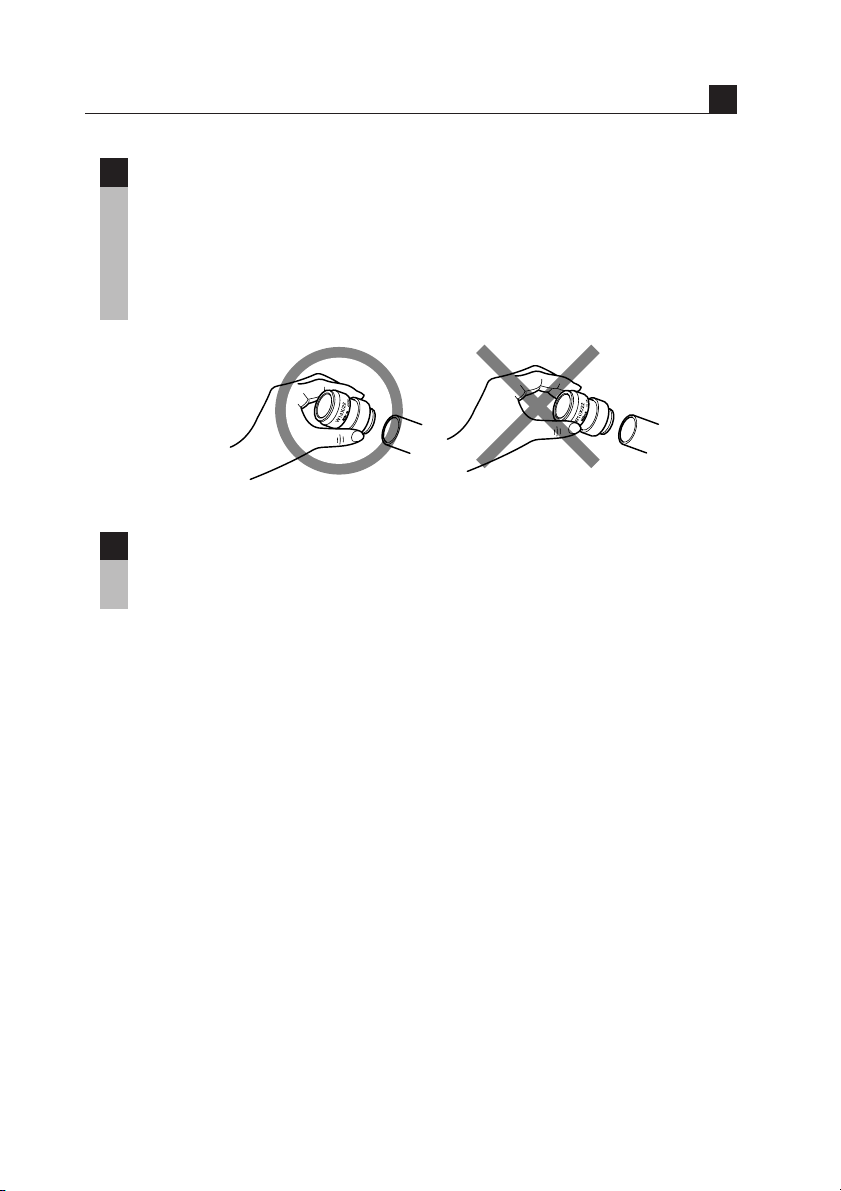
Insert the eyepieces into the eyepiece sleeves.
9
Be sure that it is inserted all the way until it touches the end of the sleeve.
Note) When inserting the eyepiece, hold the rubber cover of the eyepiece.
Holding the diopter ring causes a failure. Especially, be careful
with the 10X eyepieces because their rubber covers obstruct the
view of the sleeve end.
The hexagonal wrenches and clamp tool can be stored in the
10
pillar of the stand.
Refer to the figures on p.9 and p.11.
II
14
Page 17
III
Increasing the torque.
Usage
Preparations For Observation
1
Adjust the torque of the focus knob.
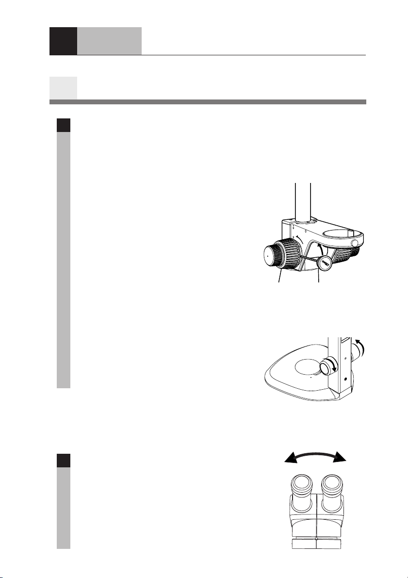
1
Adjust the torque of the focus knob so as not to fall down the zooming
body on its own weight.
[C-FMC]
Turn the torque adjustment ring using the
clamp tool. Turning the ring in the direction
of the arrow indicated on the side surface of
the focusing mount will increase the torque.
Note) • Do not twist the left and right focus
knobs.
• Do not turn the knob beyond its
turning limit.
• Do not turn the fine focus knob while
holding the coarse focus knob or vice
versa. Otherwise, the damage to the
instrument will result.
Increasing the torque.
TOR
QUE
[C-PS and C-PSC]
Rotating the left and right focus knobs in the
opposite direction as shown in the illustration
will increase the torque.
Adjust the interpupillary distance.
2
This adjustment should be performed every
time the observer is changed since the
interpupillary distance differs between
individuals. Adjust the interpupillary distance
so that the view field for each eye is merged
into one. Move while holding each sleeve
with both hands.
(To reduce the torque,
turn the knob in the direction
opposite to the arrow.)
15
Page 18

Adjust the diopter.
3
This adjustment should be performed every time the observer is changed
since the eyesight differs between individuals.
1 Turn the diopter rings on both eyepieces to set them at the 0 position
(match the 0 line with the index line).
2 Turn the zooming knob to the highest magnification. Focus on the
sample using the focus knob. (Refer to “Focusing”.)
3 Turn the zooming knob to the lowest magnification. Peering
through the left eyepiece with the left eye, focus on the sample using
the diopter ring on the left eyepiece. Then, peer through the right
eyepiece with your right eye and focus on the sample using the
diopter ring on the right eyepiece.
4 Repeat steps 2 and 3 until the image is kept focused even though the
zooming magnification is changed. This adjustment ensures sharp
image throughout the zooming range.
Focusing
2
Check the working distance.
1
The distance between the focus plane and the bottom of the objective is
called the working distance. Focusing is easier if beforehand the distance
between the specimen and the bottom of the objective is set to the working
distance. The working distance differs depending on the objective being
used. Please refer to Table 1 on p.36.
16
Focus on the sample.
2
Turning the focus knob moves the zooming body up and down and brings
focus on the sample.
[C-FMC]
Using the fine focus knob will permit the delicate focusing. Especially, it
is effective for the high magnification observation.
Page 19
Usage
Zoom
3
Change the zooming magnification.
1
Turning the zooming knobs on the left and right side of the zooming body
will change the magnification of the sample image.
■ Total Magnification
The zooming knob has the indication of the zooming magnification.
The total magnification can be found by multiplying the magnification
of the objective times that of the eyepieces.
Note) When the HR Plan Apo series objective for the SMZ1500 is used,
the total magnification will be obtained by multiplying by 1.25.
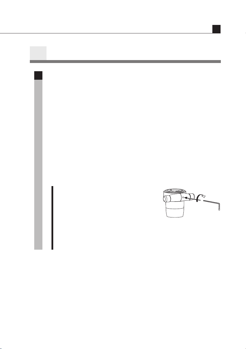
■ ON/OFF of the Zooming Knob Clicks
The clicks on the zooming knob can be
eliminated.
1 Insert the supplied hexagonal wrench
(small) or the clamp tool supplied
with the C-PS160 into the screw hole
on the rear of the zooming body.
2 Turning the inside screw in the
direction opposite to the arrow
eliminates the clicks (OFF). Turning
the same screw in the direction of the
arrow puts on back the clicks (ON).
III
17
Page 20
Usage
If You Cannot Focus On The Sample Though
4
The Zooming Body Is At The Highest Position.
When you use the 0.5X objective or observe a tall sample, you may not be
able to focus on the sample though turning the focus knob to raise the
zooming body to its highest position.
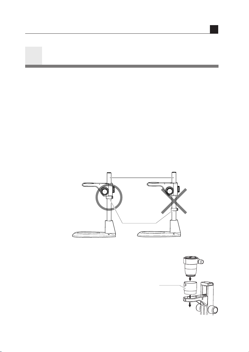
[C-PS160]
Exchange the pillar for the C-EP extension pillar available on order.
Attach the C-EP extension pillar to the stand in the same manner as for the
standard pillar. (Hold the side having the groove downward. Refer to
item 1. on p.12.) Put the stopper ring on the pillar and then the focusing
mount. Tighten the focusing mount clamp screw.
Note) Contact the bottom surface of the focusing mount with the stopper
ring and securely tighten each clamp screw.
Extension pillar
III
18
Stopper ring
Correct Wrong
[C-PS & C-PSC]
Use the C-ER auxiliary adapter available as
an option. (This adapter can’t be used for the
SMZ1000.)
• Refer to the Table 2 on p.38 for the sample heights which may be
☞
viewed.
Auxiliary
adapter
Page 21
IV
Separately
sold reticle
Reticle
Pattern
surface
Field ring
Using Accessories
Reticles
1
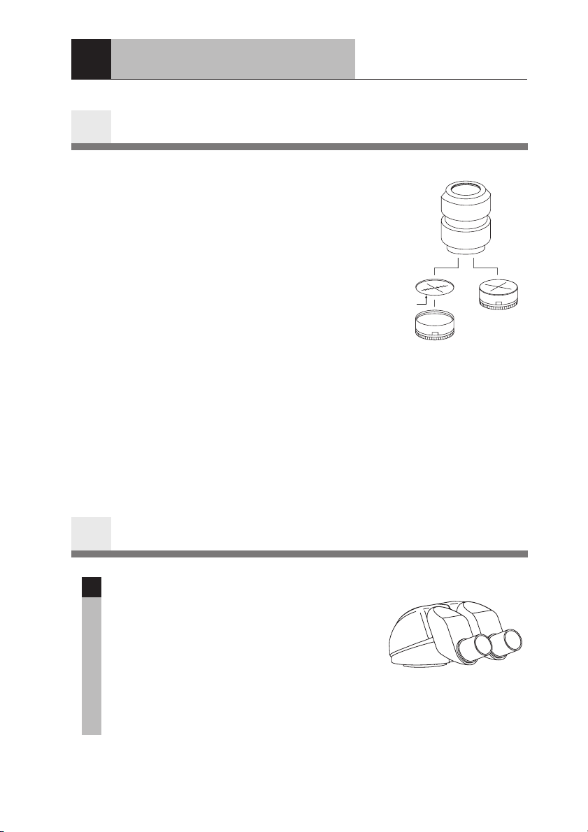
Your reticles may be attached to the eyepiece.
Once remove the field ring (or lens room of
the 20X and 30X) from the eyepiece. Attach
the reticle with its pattern surface facing down
to the eyepiece and reattach the field ring (or
lens room).
• Refer to the Table 1 on p.36 for the size
☞
of the reticle which may be attached.
Note) The 20X and 30X eyepieces adopt the
internal focusing system, and the
primary image has the magnification.
Use the reticle with 1.3X pattern for
20X eyepiece, and with 1.4X pattern
for 30X eyepiece.
A reticle with cross hairs, scaled cross
hairs, or photographic mask is
available on order for 10X eyepiece.
Eyepiece Tube
2
P-BTL low eye-level eyepiece tube
1
When using a beam splitter or coaxial
episcopic illuminator, it is possible to lower
the eye level (eye level during observation) by
using this eyepiece tube in place of the
binocular eyepiece tube.
The installation procedure for this eyepiece
tube is the same as for the P-BT binocular
eyepiece tube.
P-BTL
19
Page 22
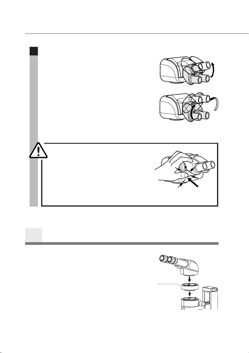
P-BERG tilted eyepiece tube
2
This eyepiece tube allows the angle of the
eyepiece sleeve to be continuously adjusted as
desired by the observer.
It is also possible to change the eye level by
rotating the interpupillary distance adjuster
(shown in gray in the illustration) 180°.
The installation procedure for this eyepiece
tube is the same as for the P-BT binocular
eyepiece tube.
P-BERG
CAUTION
P-IER Eyelevel Riser
3
When the eye level is too low, it is possible to
raise the eye level by 25 mm by attaching a
P-IER Eyelevel riser between the zooming
body and the eyepiece tube. It is possible to
use up to three Eyelevel risers at once.
Avoid using the four or more Eyelevel risers
at once or using the other intermediate tube
together such as a beam splitter or coaxial
episcopic illuminator. It may cause the
vignetting around the image periphery.
Be careful not to put your
fingers between the
interpupillary distance
adjuster and the lower part
of the eyepiece tube when
adjusting the angle of the
sleeve.
Eyelevel
riser
20
Page 23
Using Accessories
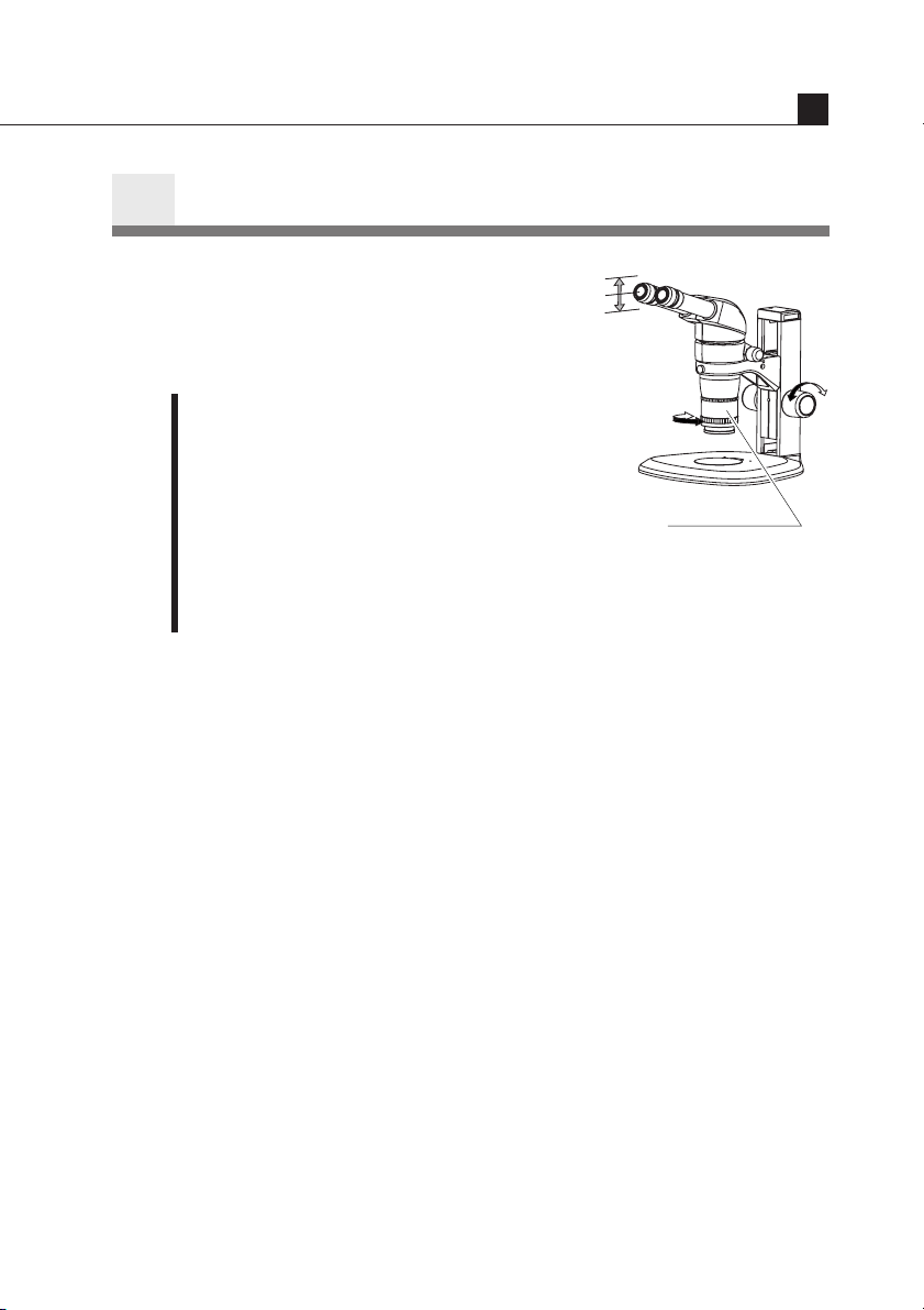
Plan 1X ERGO Objective
4
Using the Plan 1X ERGO objective allows
you to continuously change the eye level
through a 40 mm range while maintaining a
constant working distance (50 mm).
1 Rotate the upper knurled ring on the
Plan 1X ERGO objective to attach it to
the zooming body.
2 Rotate the focus knobs on the focusing
stand to raise or lower the microscope to
set to the height best suited for viewing.
3 Rotate the lower knurled ring to focus
on the specimen. Use the microscope as
usual after setting the eye level.
Note) When attaching to the SMZ1000, vignetting will occur in the lateral
direction of the viewfield at the high eye level with 1X or lower
zoom magnification.
Plan 1X ERGO
IV
21
Page 24
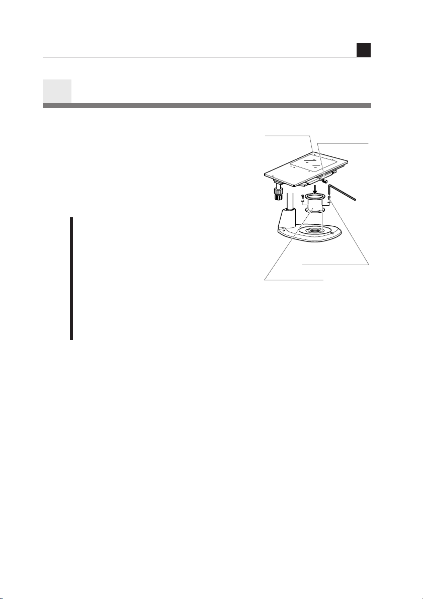
SM-S4L 4 X 4 Stage L
4 X 4 stage
Stage
clamp screw
Stage adapter
fixing screw
Stage adapter
5
SM-S4L 4 X 4 stage L may be attached by
using the C-4SA stage adapter. In this case,
use the C-ER auxiliary adapter or C-EP
extension pillar because the position of the
sample will become higher. (Refer to “4. If
you cannot focus on the sample though the
zooming body is at the highest position.”.)
1 Remove the stage plate from the stand
base, and attach the C-4SA stage
adapter in place using the fixing screws
supplied with the adapter.
2 Sufficiently loosen the stage clamp
screw of the SM-S4L 4 X 4 stage L. Fit
and mount the stage onto the stage
adapter with the side equipped with the
stage clamp screw facing front. Tighten
the stage clamp screw.
Using Accessories
IV
22
Page 25
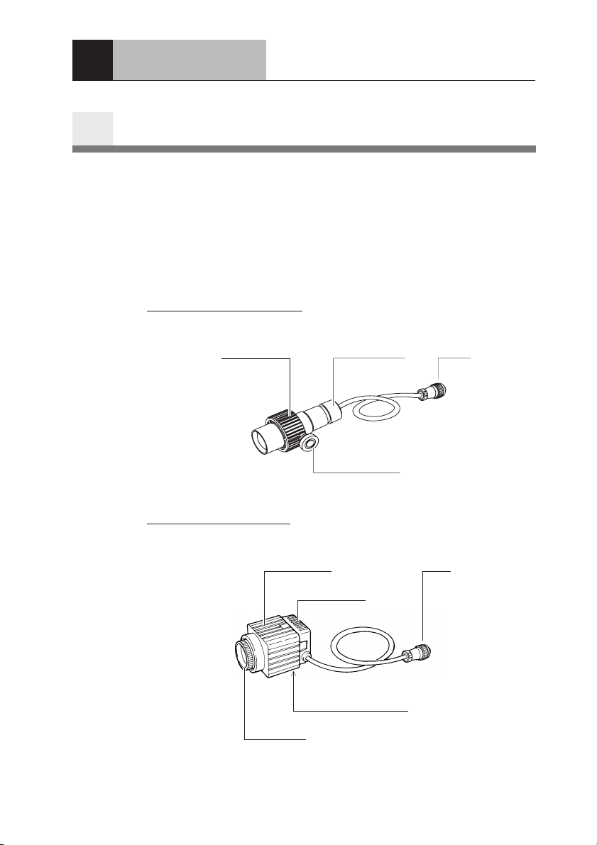
Illuminator
V
Halogen Illuminators
1
There are two illuminators available: the G-LS of 6V 10W and the CDSLS of 6V 20W.
Note) These illuminators are not adequate to observe the sample having a
high reflective surface. Use the P-ICI2 Coaxial Episcopic
Illuminator on p.29 for this purpose.
G-LS
Lamp Socket A (6V10W)
Lamp house
C-DSLS
Illuminator A (6V20W)
Lamp house
Filter cap
ø33 mm filter
attachable
Lamp socket
(may be moved
back and forth)
Mounting screw
Lamp socket
Holder and Epi arm
mounting screw hole
Plug
Plug
23
Page 26
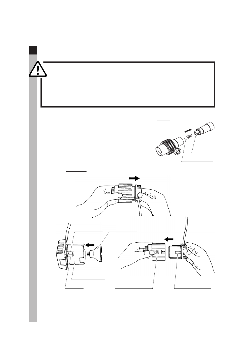
1
Lamp
CAUTION
The lamp and the surrounding area become very hot
during and immediately after using the illuminator.
Be careful not to burn yourself. In addition, be sure
the lamp has cooled sufficiently before replacing a
lamp.
Pull the lamp socket from the lamp house and
insert the lamp straight into the socket as far
as it will go. Only use halogen lamps of the
specified rating.
Next, attach the lamp socket to the lamp
house.
C-DSLS
Confirmation
window
Lamp
(Philips JCR/M
6V-20W)
G-LS
Socket
Lamp
(GE 787 6V-10W)
24
Light
shielding tube
Socket Short protrusion
Holder mounting
screw hole
Note) Do not touch the glass part of a lamp with your bare hands as your
skin may burn and stick to the lamp, possibly reducing its level of
light output or causing damage to the lamp. When replacing a
Page 27
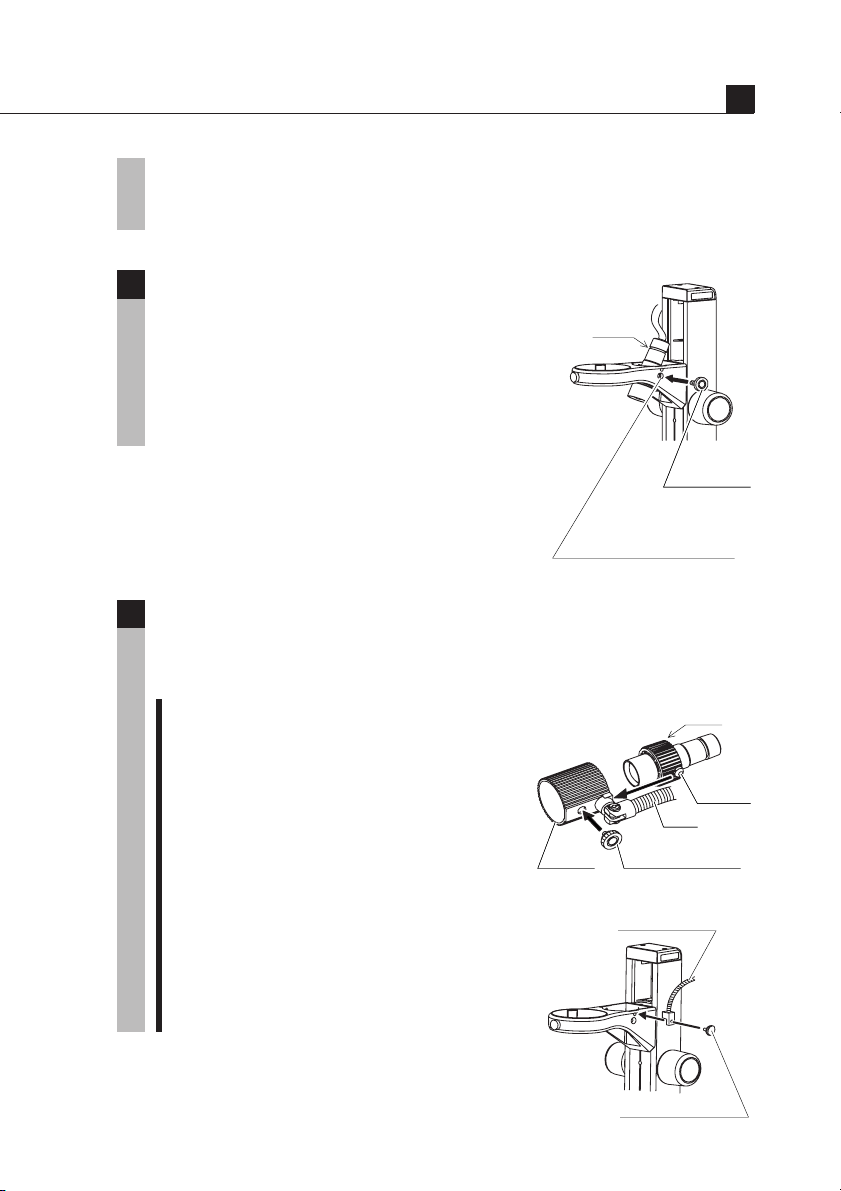
Mounting screw
Arm
Holder
Protrusion
G-LS
Illuminator
lamp, handle it through a piece of cloth or through its packaging
until replacement is complete. If you get fingerprints on the lamp,
wipe gently with a piece of clean cloth dampened with alcohol.
Attaching G-LS to the stand [C-PS & C-PSC]
2
Set so that the protrusion on the lamp house
aligns with the inside of the screw hole on the
G-LS
arm of the stand (screw hole for mounting
6V10W halogen illuminator) and secure it in
place from the outside of the arm using the
mounting screw.
Screw hole for
mounting 6V10W
halogen illuminator
Arm for halogen illuminators
3
It is possible to freely adjust the direction of illumination by using a
special arm.
V
Mounting
screw
1 G-EIA flexible arm [G-LS]
Set so that the protrusion on the lamp
house aligns with the inside of the hole
in the holder of the flexible arm and
secure it in place from the outside of the
holder using the mounting screw.
Flexible arm
Secure by screwing the mounting screw
supplied with the arm into the arm
mounting screw hole in the stand (screw
hole for mounting an Epi-arm).
Mounting screw
25
Page 28
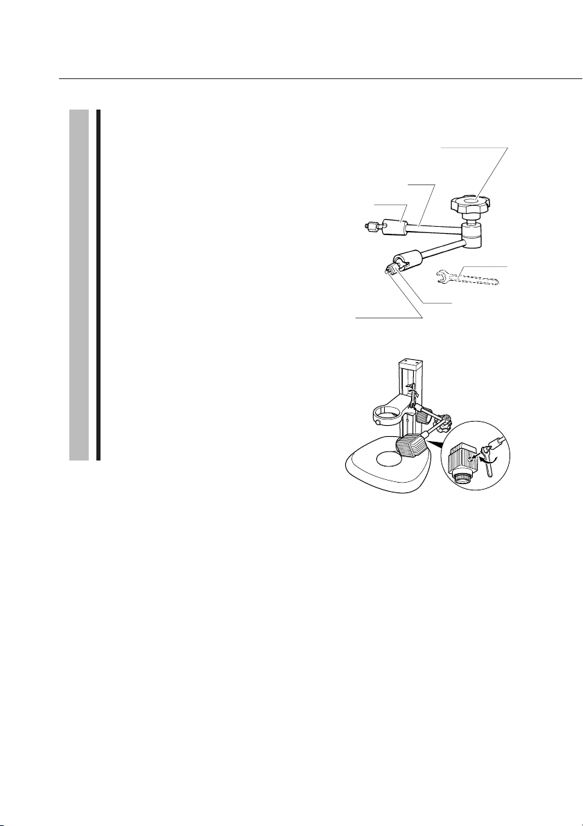
2 Epi arm
Slightly loosen the clamp knob on the
arm. Screw in the mounting screw at
the end of the Epi arm into the screw
hole of the stand (screw hole for
mounting an Epi-arm) while turning the
joint. Next, securely tighten the nut
using the supplied wrench.
Epi arm may be attached also to the
screw hole for mounting accessories of
C-PS160.
Screw the mounting screw at the other
end of the Epi arm into the screw hole
on the lamp house in the same manner
as described above. Set the lamp house
in a position that makes for easy
viewing and tighten the clamp knob.
Joint
Mounting
screw
Arm
Clamp knob
Simultaneously
clamps two
arms/joints.
Nut
Spanner
26
Page 29
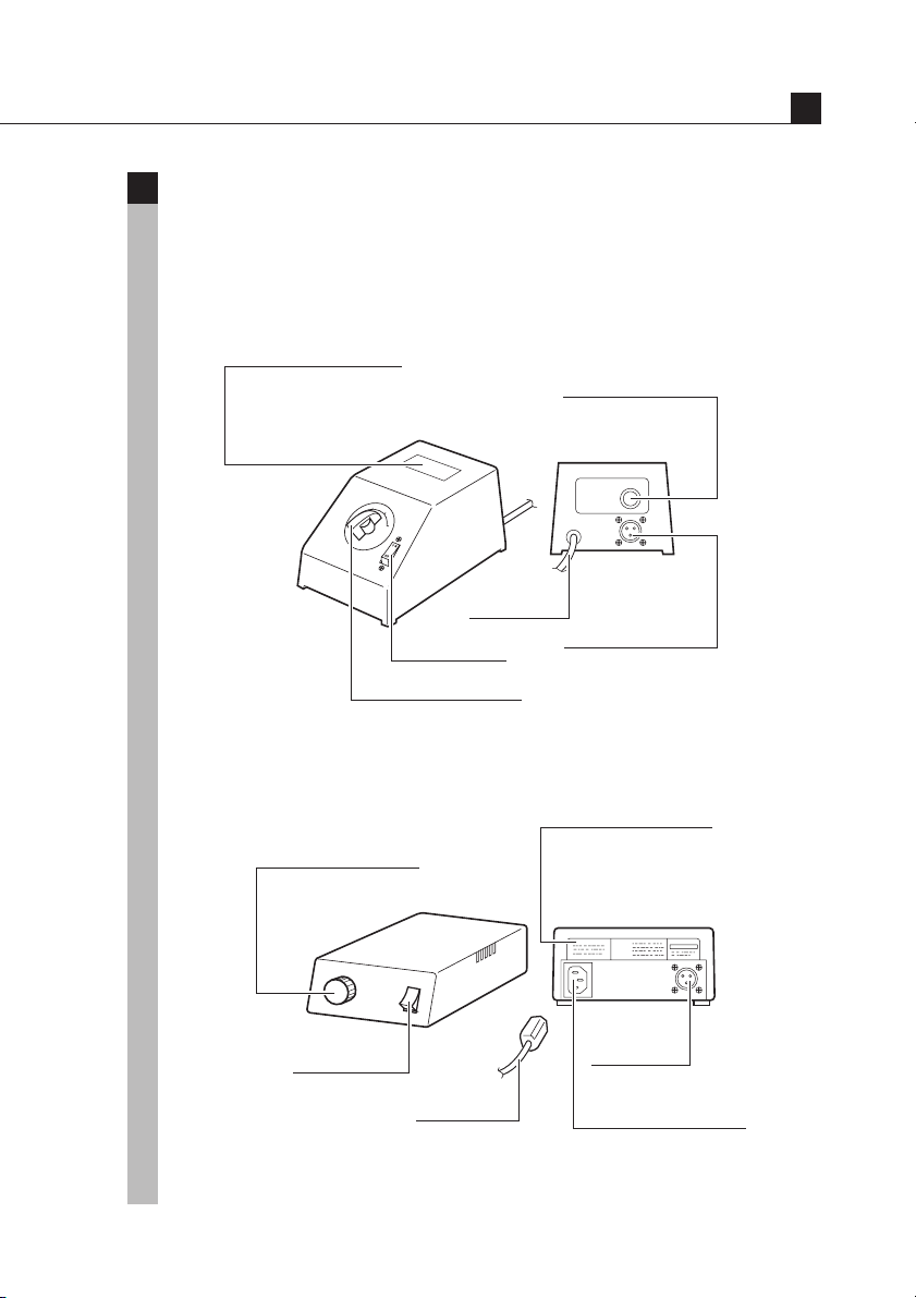
Illuminator
Power supplies
4
Use the Power Supply XN A for regions using 100/120 V power, and the
Power Supply TN-PSE30W A for regions using 230 V power. Insert the
plug of the Halogen illuminator into the output connector located on the
rear of the power supply.
Input voltage display
Check that the voltage displayed matches the
voltage used in your area. If the voltages do
not match, do not use the power supply and
contact your Nikon representative.
4
5
3
6
V
O
L
T
A
G
E
Power cord
Power switch
Brightness adjuster
Changes the illumination brightness when rotated.
Fuse
Always use the fuse
specified.
(Rear view)
Output connector
Connect the
lamphouse cable here.
V
Power Supply XN A (only for regions with 100/120 V power)
Input voltage display
Brightness adjuster
Changes the illumination
brightness when rotated.
Check that the voltage displayed
matches the voltage used in your area.
If the voltages do not match, do not
use the power supply and contact your
Nikon representative.
(Rear view)
Output
Power switch
Power cord
connector
Connect the
lamphouse cable here.
AC input connector
Connect the specified power
cord here.
Power Supply TN-PSE30W A (only for regions with 230 V power)
27
Page 30
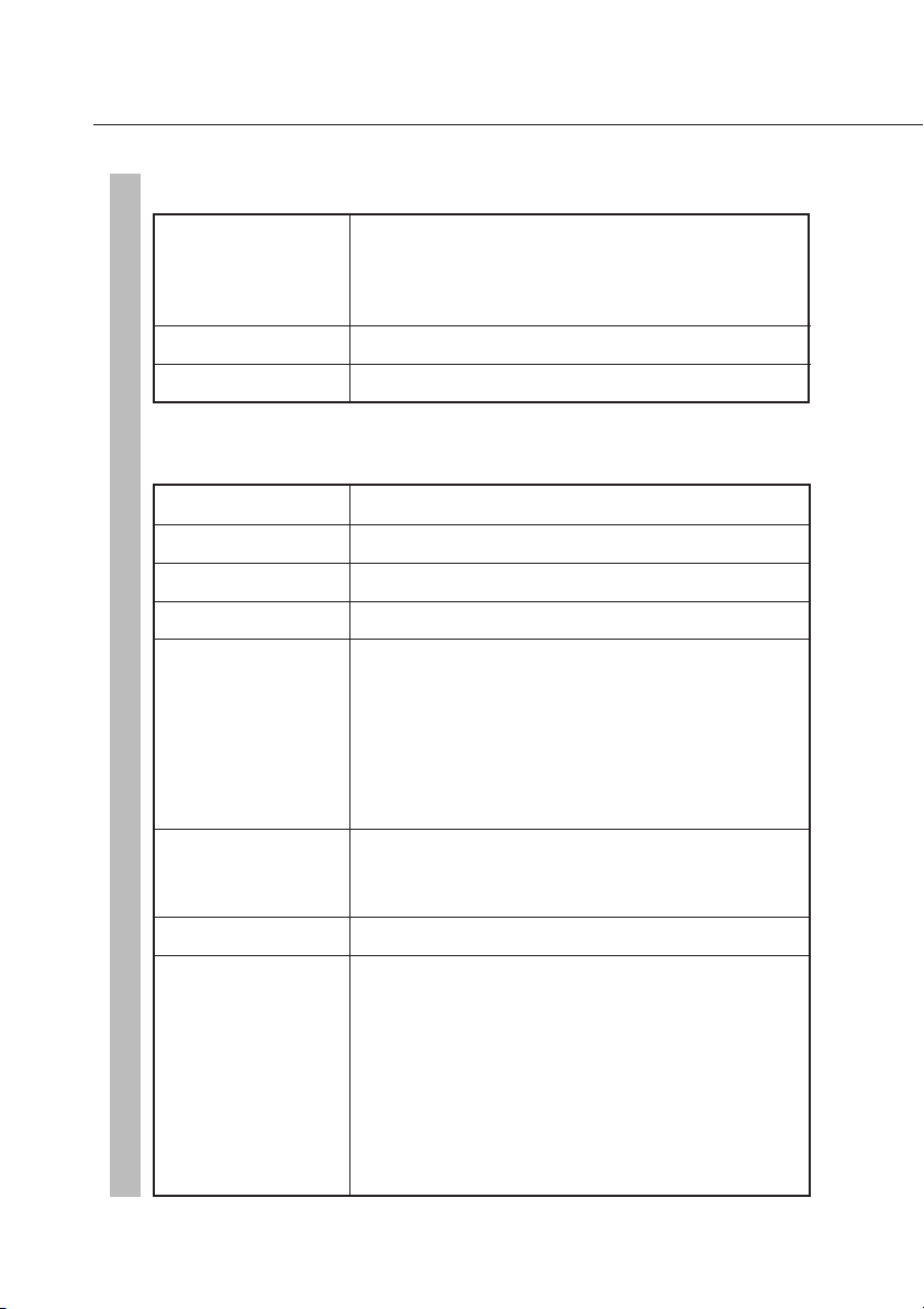
Power Supply XN A (only for regions with 100/120 V power)
Input rating Power supply for 100V regions only:
100 V AC, 50/60 Hz, 30 W
Power supply for 120V regions only:
120 V AC, 50/60 Hz, 30 W
Output rating 3-6 V AC, 3.3 A
Fuse rating 250 V, 1 A
Power Supply TN-PSE30W A (only for regions with 230 V power)
Input rating 230V AC, 50/60Hz, 0.3A
Voltage fluctuation ±10%
Output rating AC 6V 5A
Internal fuse Fast acting type, F1A/250V, 5.2 × 20 mm
Operating Altitude: 2000 m max.
environment Temperature: 0° - 40°C
(indoor use only)
Relative humidity: 85% max.
(no condensation)
Pollution level: Degree 2
Installation: Category 2
28
Storage Temperature: -20° - 60°C
environment Relative humidity: 90% max.
(no condensation)
Protection class Class 1
Power cord Use only the following power supply cord.
Using the wrong power cord could result in
danger or fire. The protection Class 1 equipment
should be connected to PE (protective earth)
terminal.
• For 220-240V AC area
Approved according to EU/EN standards, 3
conductor grounding Type H05VV-F, 3 m
long maximum, rated at 250V AC minimum.
Page 31
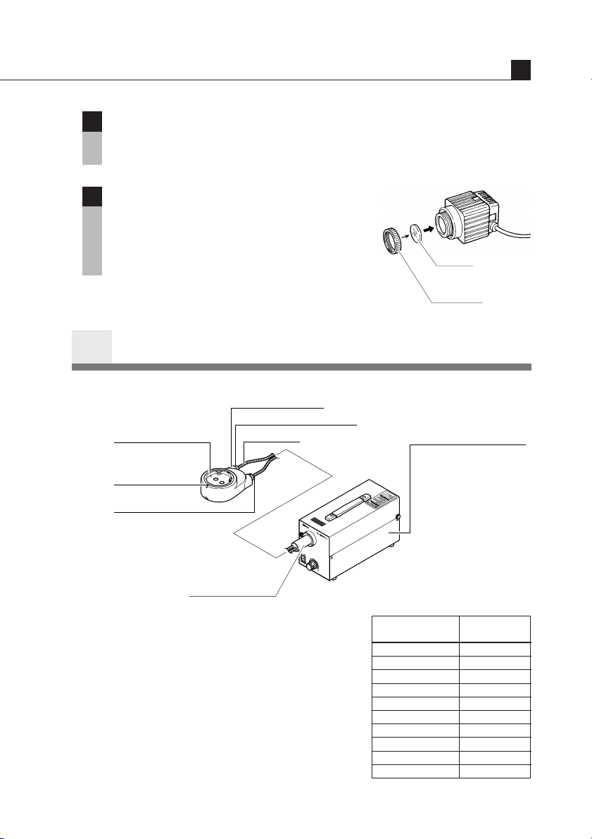
Illuminator
Lighting area adjustment [G-LS]
5
It is possible to adjust the lighting area by moving the lamp socket back
and forth. Adjust the lighting area to allow easy viewing.
Attaching filters [C-DSLS]
6
Rotate and remove the filter cap at the end of
the lamp house and insert a filter. Use filters
that have a diameter of 33 mm and a width of
1.5 ~ 2 mm.
P-ICI2 Coaxial Episcopic Illuminator
2
Light guide mount
Light guide clamp screw
Main body
Eyepiece tube
clamp screw
Luminous section
Light guide
Filter
ø33 mm
Filter cap
Fiber illuminator
Fiber illuminator (C-FI115 for
100/120V region and C-FI230
for 230V region) available on
order is necessary for the
light source.
Read also the Instruction
Manual of the Fiber
Illuminator C-FI115/C-FI230.
V
Incident section
Magnification of the P-ICI2 Coaxial
Episcopic Illuminator is 1.5X. Total
magnification is obtained by multiplying 1.5
by the total magnification of the basic set of
the microscope.
Note) Usable magnification for the P-ICI2
Coaxial Episcopic Illuminator is
restricted. Use the magnification
within the range shown in the right
Objective
Acro 0.5X 3X or higher
Plan 1X 1.5X or higher
Plan 1X ERGO 1.5X or higher
Plan Apo 0.5X 4X or higher
Plan Apo 1X 2X or higher
ED Plan 1.5X 2X or higher
ED Plan 2X Not usable
HR Plan Apo 0.5X 2.5X or higher
HR Plan Apo 1X 2.5X or higher
HR Plan Apo 1.6X Not usable
Zooming
magnification
29
Page 32
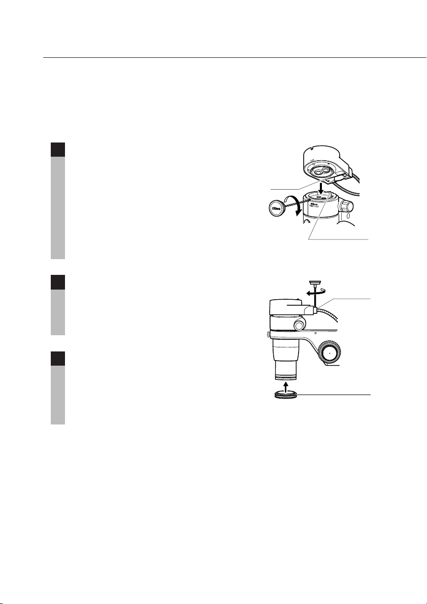
table. If the magnification out of the
Groove
Positioning pin
specified range is used, uneven
illumination will occur or the seeing of
the sample image will be degraded.
Mount the P-ICI2 onto the zooming body
1
aligning the groove on the bottom of the
P-ICI2 main body with the positioning pin on
the zooming body while tilting the P-ICI2
toward the rear. Tighten the eyepiece tube
clamp screw.
Note) When the other intermediate tube such
as a beam splitter is used together,
attach it on the P-ICI2.
Screw in the 1/4 lambda plate to the end of
2
the objective. When the C-FIR ring fiber light
guide is used together, use the other 1/4
lambda plate separately available for ring
fiber illuminator.
Insert the incident section of the light guide
3
into the light guide mount of the fiber
illuminator and tighten the clamp screw.
Insert the luminous section of the light guide
into the light guide mount of the P-ICI2 and
tighten the clamp screw.
Luminous
section
1/4 lambda plate
30
Page 33
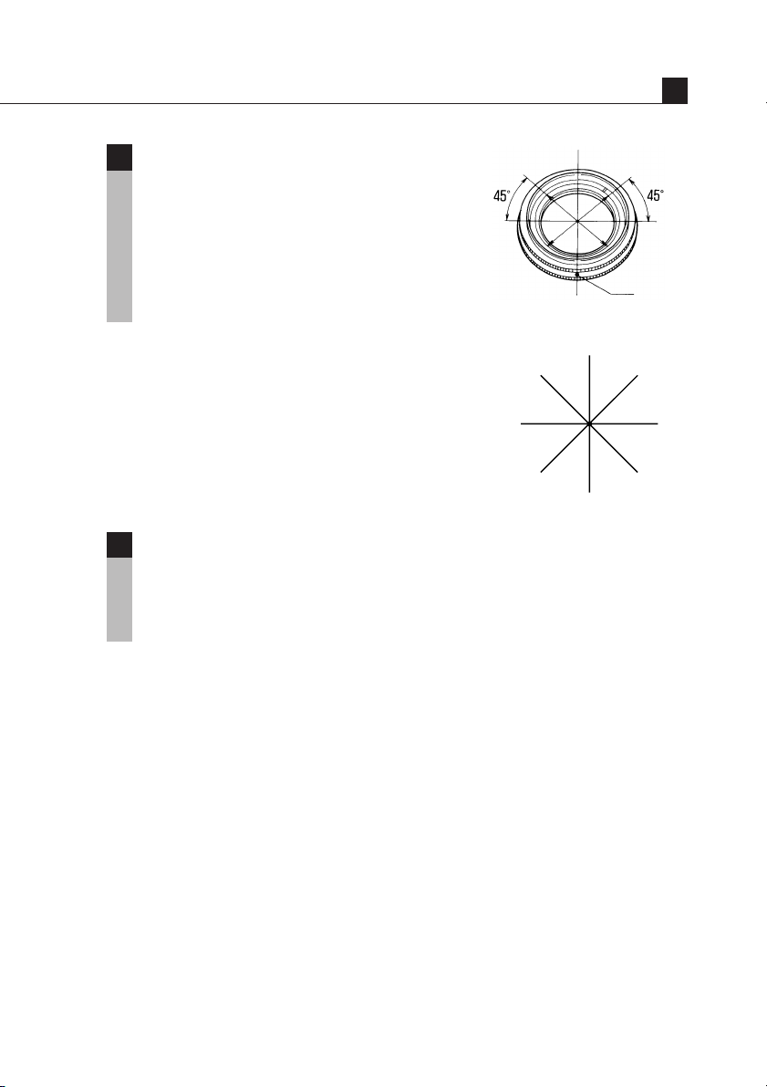
The optical axis of the 1/4 lambda plate is at
Bright
Bright
Bright
Bright
Dark
Dark Dark
Dark
4
the 45° position from the red dot. Brightness
is the maximum when the red dot is
positioned at the front and switches from
bright to dark by each 45° position. Adjust
the plate to the position where the brightness
and contrast are best suited for the
observation.
Insert the filter P-ICI33 NCB14 into the fiber
5
illuminator to improve the color
reproducibility when taking a
photomicrogaph. Refer to the instruction
manual of Fiber Illuminator.
Illuminator
Red dot
V
31
Page 34
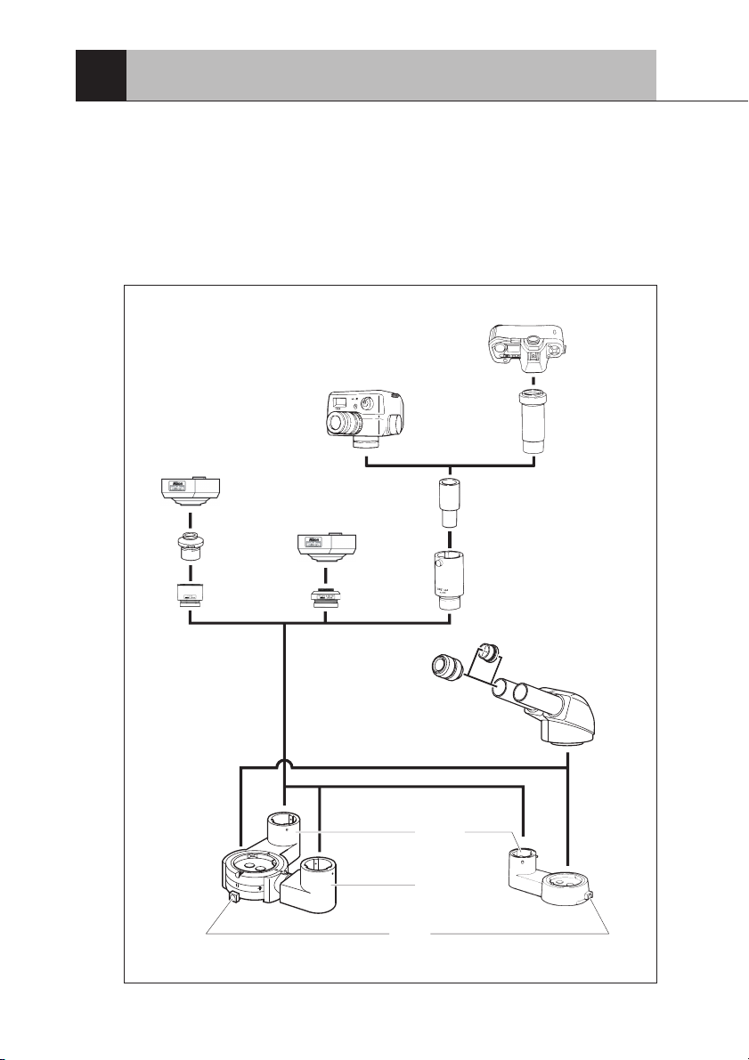
VI
Photomicrographic and TV-related Accessories
It is possible to photograph images or display them on a TV monitor by
attaching a beam splitter between the zooming body and the eyepiece tube.
There are two beam splitters available: the S2 P-IBSS2 with one port and
the D2 P-IBSD2 with two ports.
Read also the instruction manual of the instrument such as a
photomicrographic equipment or TV camera to be used.
F-mount camera
Photomicrographic
equipment FX-III series
C-mount camera
for digital cameras
such as DS-5M
F-mount
camera adapter
Digital camera
DS-2M
C-mount
TV adapter
LV-TV tube
Optical path switching knob Optical path switching knob
Beam splitter D2
0.55x
relay lens
Eyepiece
Rear port Port
Side port
CF PLI projection lens
(5X, 4X, 2.5X, 2X)
Photomicrographic
equipment adapter
Photo reticle
Binocular
eyepiece tube
Beam splitter S2
32
Page 35
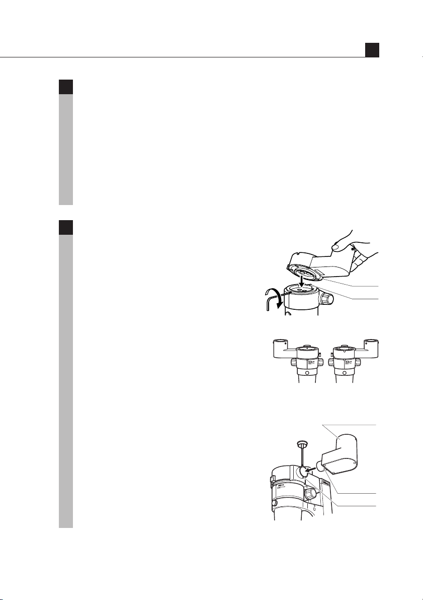
Photomicrographic and TV-related accessories
Photomicrographic magnification
1
Photomicrographic magnification = (PLI projection lens magnification)
× (Zoom magnification) × (Objective magnification)
• When the P-ICI2 Coaxial Episcopic Illuminator is used:
Photomicrographic magnification = (PLI projection lens magnification)
× (Zoom magnification) × (Objective magnification) × 1.5
• When the HR Plan Apo series objective is used:
Photomicrographic magnification = (PLI projection lens magnification)
× (Zoom magnification) × (Objective magnification) × 1.25
Attaching the beam splitter
2
Mount the beam splitter onto the zooming
body aligning the groove on the bottom of the
beam splitter with the positioning pin on the
zooming body while tilting the beam splitter
toward the rear. Tighten the eyepiece tube
clamp screw.
[P-IBSS2] Mount it so as to position the
port at either the left or right.
VI
Groove
Pin
[P-IBSD2] 1) Mount it so as to position the
rear port at the rear.
2) Attach the side port to the
beam splitter main body with
the positioning pin on the
side port fitted into the
groove on the beam splitter
main body. Tighten the side
port clamp screw.
P-IBSS2 Port location
Side port
Pin
Groove
P-IBSD2 Attaching side port
33
Page 36
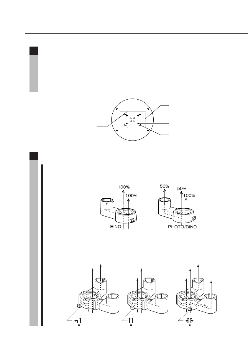
Photo reticles
3
Attaching the C-FP photo reticle to the C-W10X eyepiece permits you to
make focusing for phtotomicrography through the eyepiece. Select the
correct frame indicating the area being photographed according to the
magnification of the PLI projection lens. For more accurate focusing and
photographing area, use the finder of the photomicrographic equipment.
2X projection lens,
35-mm full size
2.5X projection lens,
35-mm half size
Photomicrography procedure
4
1 Switching the optical path
[P-IBSS2] Set the optical path switching knob to PHOTO/BINO.
[P-IBSD2] Set the optical path switching knob to the left or right.
Setting it to the left allows you to use only the rear port
and setting it to the right, both the rear and side ports.
100%
100%
100%
100%
2.5X projection lens,
35-mm full size
5X projection lens,
35-mm full size
4X projection lens,
35-mm full size
50%
50%
50%
50%
34
Page 37
Photomicrographic and TV-related accessories
2 Focusing
The following is the focusing procedure using the photo reticle. For
the focusing procedure using the finder of the photomicrographic
equipment, refer to the instruction manual of the phtotomicrographic
equipment.
1 Once remove the field ring of the
eyepiece and attach the photo mask
reticle. (Refer to p.19 "1. Reticles".)
2 Turn the diopter ring to focus on the
reticle.
3 Turn the focus knob to focus on both
the reticle and the image.
VI
Note) [P-IBSD2]
You can not observe the image
through the left eyepiece if the
Adjust so that the double
crosshairs is clearly
divided in two
optical path switching knob is set
to the left. In this case, use the
finder of the photomicrographic
equipment for focusing.
Focusing with the right eyepiece
or focusing with the optical path
switching knob set to the position
other than left may result in
defocusing.
3 Adjusting the frame position
Turn the eyepiece to align each frame of the photo mask and the
photomicrographic equipment finder. Note that the image seen
through the finder is reversed from that seen through the eyepiece.
Finder and eyepiece images
Eyepiece
Finder
35
Page 38

Magnification 1.3X Magnification 1.4X
Eyepieces
10 X 15 X 20 X 30 X
Table 1: Total Magnification and Real Field
Field number 22 Field number 16 Field number 12.5 Field number 7
Working
distance
Total Real field Total Real field Total Real field Total Real field
Objectives [mm] Reticle diameter ø25 Reticle diameter ø19 Reticle diameter ø19 Reticle diameter ø12
magnification [mm] magnification [mm] magnification [mm] magnification [mm]
36
SMZ1000
Acro 0.5 X 189 4 ~ 40 X 55.0 ~ 5.5 6 ~ 60 X 40.0 ~ 4.0 8 ~ 80 X 31.3 ~ 3.1 12 ~ 120 X 17.5 ~ 1.8
Plan 1 X 78 8 ~ 80 X 27.5 ~ 2.8 12 ~ 120 X 20.0 ~ 2.0 16 ~ 160 X 15.6 ~ 1.6 24 ~ 240 X 8.8 ~ 0.9
Plan 1 X ERGO 50 8 ~ 80 X 27.5 ~ 2.8 12 ~ 120 X 20.0 ~ 2.0 16 ~ 160 X 15.6 ~ 1.6 24 ~ 240 X 8.8 ~ 0.9
Plan Apo 0.5 X 123 4 ~ 40 X 55.0 ~ 5.5 6 ~ 60 X 40.0 ~ 4.0 8 ~ 80 X 31.3 ~ 3.1 12 ~ 120 X 17.5 ~ 1.8
Plan Apo 1 X 70 8 ~ 80 X 27.5 ~ 2.8 12 ~ 120 X 20.0 ~ 2.0 16 ~ 160 X 15.6 ~ 1.6 24 ~ 240 X 8.8 ~ 0.9
ED Plan 1.5 X 44.5 12 ~ 120 X 18.3 ~ 1.8 18 ~ 180 X 13.3 ~ 1.3 24 ~ 240 X 10.4 ~ 1.0 36 ~ 360 X 5.8 ~ 0.6
ED Plan 2 X 32.5 16 ~ 160 X 13.8 ~ 1.4 24 ~ 240 X 10.0 ~ 1.0 32 ~ 320 X 7.8 ~ 0.8 48 ~ 480 X 4.4 ~ 0.4
HR Plan Apo 0.5 X 136 5 ~ 50 X 44.0 ~ 4.4 7.5 ~ 75 X 32.0 ~ 3.2 10 ~ 100 X 25 ~ 2.5 15 ~ 150 X 14 ~ 1.4
HR Plan Apo 1 X 54 10 ~ 100 X 22.0 ~ 2.2 15 ~ 150 X 16.0 ~ 1.6 20 ~ 200 X 12.5 ~ 1.3 30 ~ 300 X 7 ~ 0.7
HR Plan Apo 1.6 X 24 16 ~ 160 X 13.8 ~ 1.4 24 ~ 240 X 10.0 ~ 1.0 32 ~ 320 X 7.8 ~ 0.8 48 ~ 480 X 4.4 ~ 0.4
Page 39

Eyepieces
Table 1: Total Magnification and Real Field
Magnification 1.3X Magnification 1.4X
SMZ800
10 X 15 X 20 X 30 X
Field number 22 Field number 16 Field number 12.5 Field number 7
Working
distance
Total Real field Total Real field Total Real field Total Real field
Objectives [mm] Reticle diameter ø25 Reticle diameter ø19 Reticle diameter ø19 Reticle diameter ø12
magnification [mm] magnification [mm] magnification [mm] magnification [mm]
Acro 0.5 X 189 5.0 ~ 31.5 X 44.0 ~ 7.0 7.5 ~ 47.3 X 32.0 ~ 5.1 10.0 ~ 63.0 X 25.0 ~ 4.0 15.0 ~ 94.5 X 14.0 ~ 2.2
Plan 1 X 78 10.0 ~ 63.0 X 22.0 ~ 3.5 15.0 ~ 94.5 X 16.0 ~ 2.5 20.0 ~ 126.0 X 12.5 ~ 2.0 30.0 ~ 189.0 X 7.0 ~ 1.1
Plan 1 X ERGO 50 10.0 ~ 63.0 X 22.0 ~ 3.5 15.0 ~ 94.5 X 16.0 ~ 2.5 20.0 ~ 126.0 X 12.5 ~ 2.0 30.0 ~ 189.0 X 7.0 ~ 1.1
Plan Apo 0.5 X 123 5.0 ~ 31.5 X 44.0 ~ 7.0 7.5 ~ 47.3 X 32.0 ~ 5.1 10.0 ~ 63.0 X 25.0 ~ 4.0 15.0 ~ 94.5 X 14.0 ~ 2.2
Plan Apo 1 X 70 10.0 ~ 63.0 X 22.0 ~ 3.5 15.0 ~ 94.5 X 16.0 ~ 2.5 20.0 ~ 126.0 X 12.5 ~ 2.0 30.0 ~ 189.0 X 7.0 ~ 1.1
ED Plan 1.5 X 44.5 15.0 ~ 94.5 X 14.7 ~ 2.3 22.5 ~ 141.8 X 10.7 ~ 1.7 30.0 ~ 189.0 X 8.3 ~ 1.3 45.0 ~ 283.5 X 4.7 ~ 0.7
ED Plan 2 X 32.5 20.0 ~ 126.0 X 11.0 ~ 1.7 30.0 ~ 189.0 X 8.0 ~ 1.3 40.0 ~ 252.0 X 6.3 ~ 1.0 60.0 ~ 378.0 X 3.5 ~ 0.6
HR Plan Apo 0.5 X 136 6.3 ~ 39.4 X 35.2 ~ 5.6 9.4 ~ 59.1 X 25.6 ~ 4.1 12.5 ~ 78.8 X 20.0 ~ 3.2 18.8 ~ 118.1 X 11.2 ~ 1.8
HR Plan Apo 1 X 54 12.5 ~ 78.8 X 17.6 ~ 2.8 18.8 ~ 118.1 X 12.8 ~ 2.0 25.0 ~ 157.5 X 10.0 ~ 1.6 37.5 ~ 236.3 X 5.6 ~ 0.9
HR Plan Apo 1.6 X 24 20.0 ~ 126.0 X 11.0 ~ 1.7 30.0 ~ 189.0 X 8.0 ~ 1.3 40.0 ~ 252.0 X 6.3 ~ 1.0 60.0 ~ 378.0 X 3.5 ~ 0.6
37
Page 40

Table 2: Observable Sample Heights [mm]
SMZ1000 + C-PS160 + C-FMC
Table 2: Observable Sample Heights
Mount Mount up When using
Objectives normal side down C-EP
position position extension pillar
Acro 0.5X 0 ~ 24 — 0 ~ 124 0 ~ 13
Plan 1X 0 ~ 97 0 ~ 42 0 ~ 197 0 ~ 86
Plan 1X ERGO 0 ~ 114 0 ~ 59 0 ~ 214 0 ~ 103
Plan Apo 0.5X 0 ~ 25 — 0 ~ 125 0 ~ 14
Plan Apo 1X 0 ~ 102 0 ~ 47 0 ~ 202 0 ~ 91
ED Plan 1.5X 0 ~ 111 0 ~ 56 0 ~ 211 0 ~ 100
ED Plan 2X 0 ~ 108 0 ~ 53 0 ~ 208 0 ~ 97
HR Plan Apo 0.5X 0 ~ 33 — 0 ~ 133 0 ~ 22
HR Plan Apo 1X 0 ~ 103 0 ~ 48 0 ~ 203 0 ~ 92
HR Plan Apo 1.6X 0 ~ 112 0 ~ 57 0 ~ 212 0 ~ 101
When using
SM-S4L
and C-EP
extension pillar
SMZ800 + C-PS
Objectives
Acro 0.5X 0 ~ 2 — 0 ~ 58 —
Plan 1X 0 ~ 75 0 ~ 20 26 ~ 131 0 ~ 20
Plan 1X ERGO 0 ~ 92 0 ~ 37 3 ~ 148 0 ~ 37
Plan Apo 0.5X 0 ~ 3 — 0 ~ 59 —
Plan Apo 1X 0 ~ 81 0 ~ 26 32 ~ 137 0 ~ 25
ED Plan 1.5X 0 ~ 89 0 ~ 34 40 ~ 145 0 ~ 34
ED Plan 2X 0 ~ 87 0 ~ 32 38 ~ 143 0 ~ 31
HR Plan Apo 0.5X 0 ~ 11 — 0 ~ 67 —
HR Plan Apo 1X 0 ~ 82 0 ~ 27 33 ~ 138 0 ~ 27
HR Plan Apo 1.6X 0 ~ 90 0 ~ 35 41 ~ 146 0 ~ 35
Arm normal Arm lower When using
position position auxiliary adapter
When using
SM-S4L and
auxiliary adapter
38
 Loading...