

Page 1

M608 E 13.5.NF.1
Research Stereo Microscope
SMZ25/SMZ18
*M608EN01*
Instruction Manual
Page 2

Page 3

Introduction
Introduction
Thank you for purchasing a Nikon product.
This instruction manual is written for users of the Nikon research stereo microscopes for SMZ25 Zooming Body/SMZ18
Zooming Body. To ensure correct usage, read this manual carefully before operating this product.
● No part of this manual may be reproduced or transmitted in any form without prior written permission from Nikon.
● The contents of this manual are subject to change without notice.
● The equipment described in this manual may differ from the actual product in its appearance.
● Although every effort has been made to ensure the accuracy of this manual, errors or inconsistencies may remain. If you
note any points that are unclear or incorrect, please contact your nearest Nikon representative.
● Some of the equipment described in this manual may not be included in the set you have purchased.
● If you intend to use any other equipment with this product, read the manual for that equipment too.
● If this equipment is used in a manner not specified by the manufacturer, the protection provided by the equipment may be
impaired.
i
Page 4
Introduction
Contents of the Manual
Chapter 1, “Components” in this instruction manual is presented, based on the system configuration examples of SMZ25
Zooming Body and SMZ18 Zooming Body. Chapter 2, “Microscopy Procedures” describes three different microscopy
procedures in accordance with the configuration examples in Chapter 1. Chapter 3, “Operations for Each Purpose”
describes which operations are to be performed, followed by Chapter 4, “Functions and Operations of the Devices.”
Chapter 5, “Assembling” lists the components of this microscopy system, considering that the system allows various
combination. Devices needed for each illumination method can be identified.
Symbols Used in This Manual
The following symbols are used in this manual.
Symbols for Safety
WARNING
CAUTION
Other Symbols
Highlights important information that should be noted for safety. Read “Safety Precautions” for details.
Indicates information you should note or comply with to prevent defects or malfunction of this product.
Indicates information you should be aware of in using this product, as well as other useful information.
ii
Page 5

Contents
Contents
Introduction ......................................................................................................................... i
Contents of the Manual .................................................................................................... ii
Symbols Used in This Manual ......................................................................................... ii
Safety Precautions ............................................................................................................ vi
WARNING and CAUTION Symbols ................................................................................ vi
Label Attached to the Product ......................................................................................... vi
WARNING ................................................................................................................ viii
CAUTION ................................................................................................................... x
Notes on Handling the Product ........................................................................................ xii
Components ............................................................................................. 1
1 Microscopy System under Episcopic Illumination .................................................... 2
1.1 Names of the Devices and Operation Sections .................................................. 2
2 Microscopy System under Diascopic Illumination and Epi-fluorescence
Illumination ............................................................................................................... 3
2.1 Names of the Devices and Operation Sections .................................................. 3
2.2 Buttons on the P2-RC Remote Controller .......................................................... 4
3 Compact System ...................................................................................................... 5
3.1 Names of the Devices and Operation Sections .................................................. 5
Microscopy Procedures .......................................................................... 7
1 Operation Flowchart ................................................................................................. 8
2 Procedure for Microscopy under Episcopic Illumination ........................................... 9
3 Procedure for Microscopy under Diascopic Illumination ........................................ 13
4 Procedure for Epi-fluorescence Microscopy ........................................................... 16
Specific Operations ............................................................................... 19
1 Turning On the Power ............................................................................................ 20
2 Adjusting the Brightness ......................................................................................... 21
3 Switching the Optical Path of the Tube .................................................................. 22
4 Adjusting the Angle of Depression ......................................................................... 23
5 Adjusting the Diopter .............................................................................................. 23
6 Adjusting the Interpupillary Distance ...................................................................... 24
7 Focusing on the Sample ......................................................................................... 25
8 Changing the Magnification .................................................................................... 27
8.1 Image Zooming ................................................................................................. 27
8.2 Switching Objectives (Using the P2-RNI2 Intelligent Nosepiece) .................... 28
9 Shifting a Sample ................................................................................................... 29
9.1 Shifting the Stage in the X and Y Directions (P-SXY64 XY Stage) .................. 29
9.2 Using the Sliding Stage ..................................................................................... 29
10 Using the Aperture Diaphragm ............................................................................... 30
11 Using Episcopic Illumination ................................................................................... 30
12 Using Diascopic Illumination .................................................................................. 31
13 Using Epi-Fluorescence Illumination ...................................................................... 32
iii
Page 6

Contents
13.1 Switching Filter Cubes ...................................................................................... 32
13.2 Selecting a Filter Cube ..................................................................................... 33
13.3 Important Notes for Epi-Fluorescence Microscopy .......................................... 33
14 Remote Operation .................................................................................................. 33
15 Capturing Images ................................................................................................... 34
15.1 Procedure for Capturing Images ...................................................................... 34
15.2 Tips on Microscope Settings for Photomicroscopy........................................... 35
16 Internally Saved Information ................................................................................... 36
Functions and Operations of the Devices ........................................... 37
1 Zooming Body ........................................................................................................ 38
1.1 SMZ18 Zooming Body ...................................................................................... 38
1.2 SMZ25 Zooming Body ...................................................................................... 39
2 Focus Units............................................................................................................. 41
2.1 P2-FU Focus Unit ............................................................................................. 41
2.2 P2-MFU Motorized Focus Unit ......................................................................... 42
2.3 P2-FMDN Focus Mount .................................................................................... 45
3 Nosepiece .............................................................................................................. 46
3.1 P2-RNI2 Intelligent Nosepiece ......................................................................... 46
4 Objectives ............................................................................................................... 47
5 Bases, Stand, and Stages ...................................................................................... 48
5.1 P2-PB Plain Base ............................................................................................. 48
5.2 P2-DBL LED Diascopic Illumination Base ........................................................ 48
5.3 P2-DBF Fiber Diascopic Illumination Base ...................................................... 48
5.4 P-PS32 Plain Stand .......................................................................................... 49
5.5 P-SXY64 XY Stage ........................................................................................... 50
5.6 C-SSL DIA Sliding Stage .................................................................................. 50
5.7 C-TRS Tilting Stage .......................................................................................... 50
6 Tubes ...................................................................................................................... 51
6.1 P2-TERG 100/ P2-TERG 50 Trinocular Tilting Tube ........................................ 51
6.2 P2-TL100 Trinocular Tube L ............................................................................. 51
7 Episcopic Illuminator .............................................................................................. 52
7.1 P2-CI Coaxial Epi Illuminator ............................................................................ 52
7.2 C-FDF Flexible Double Arm Fiber Illumination Unit .......................................... 53
7.3 P2-FIR Ring Fiber Illumination Unit .................................................................. 53
7.4 P2-FIRL LED Ring Illumination Unit ................................................................. 53
8 Diascopic Illuminator .............................................................................................. 54
8.1 P2-DBL LED Diascopic Illumination Base ........................................................ 54
8.2 P2-DBF Fiber Diascopic Illumination Base ...................................................... 56
8.3 P-DF LED Dark Field Unit................................................................................. 57
8.4 P2-POL Simple Polarizing Attachment ............................................................. 57
9 Epi-Fluorescence Attachment................................................................................. 58
9.1 P2-EFLI Epi Fluorescence Attachment ............................................................. 58
9.2 P2-EFLM Motorized Epi Fluorescence Attachment .......................................... 59
10 Remote Control Device .......................................................................................... 61
10.1 P2-RC Remote Controller ................................................................................. 61
10.2 AZ-FSW Foot Switch ........................................................................................ 63
10.3 AZ-PCR Photo Release .................................................................................... 65
11 Control/Communications Device and Relay Device ............................................... 66
11.1 P2-CTLB Control Box ....................................................................................... 66
11.2 P2-CTLA Control Box ....................................................................................... 68
11.3 P2-RLY Relay Box ............................................................................................ 69
11.4 P2-RLYC Relay Cable ...................................................................................... 69
iv
Page 7

Contents
Assembling ............................................................................................ 71
1 System Configuration ............................................................................................. 72
2 Device List .............................................................................................................. 74
3 Assembly Procedures ............................................................................................ 75
3.1 Assembling the EPI System and DIA + EPI-FL System ................................... 75
3.2 Compact System Assembly .............................................................................. 91
3.3 Assembly of Other Devices (Optional) ............................................................. 94
Troubleshooting ..................................................................................... 97
1 Image Viewing ........................................................................................................ 98
2 Operation ................................................................................................................ 98
3 Motorized Devices .................................................................................................. 99
Maintenance and Storage ................................................................... 101
1 Cleaning ............................................................................................................... 102
1.1 Cleaning Lenses ............................................................................................. 102
1.2 Cleaning Parts Other than the Lens ............................................................... 102
1.3 Disinfecting the Product .................................................................................. 103
2 Storage ................................................................................................................. 103
3 Periodic Inspection (Charged) .............................................................................. 103
Specifications ...................................................................................... 105
1 Microscopy (Principles) ........................................................................................ 106
2 Performance Properties ....................................................................................... 106
3 Physical Properties ................................................................................................ 110
v
Page 8
Safety Precautions
Safety Precautions
To ensure correct and safe operation, read this manual before using this product.
WARNING and CAUTION Symbols
Although this product is designed and manufactured to be completely safe during use, incorrect usage or failure to follow the
safety instructions provided may cause personal injury or property damage. To ensure correct usage, read this manual
carefully before using this product. Do not discard this manual and keep it handy for easy reference.
Safety instructions in this manual are marked with the following symbols to indicate their importance. For your safety, always
follow the instructions marked with these symbols.
Symbol Description
Disregarding instructions marked with this symbol may lead to serious injury or death.
Disregarding instructions marked with this symbol may lead to injury or property damage.
WARNING
CAUTION
Label Attached to the Product
The label attached to the products shown below indicates that attention should be paid to use of these products. Before using
a product with the label attached, be sure to carefully read the manual.
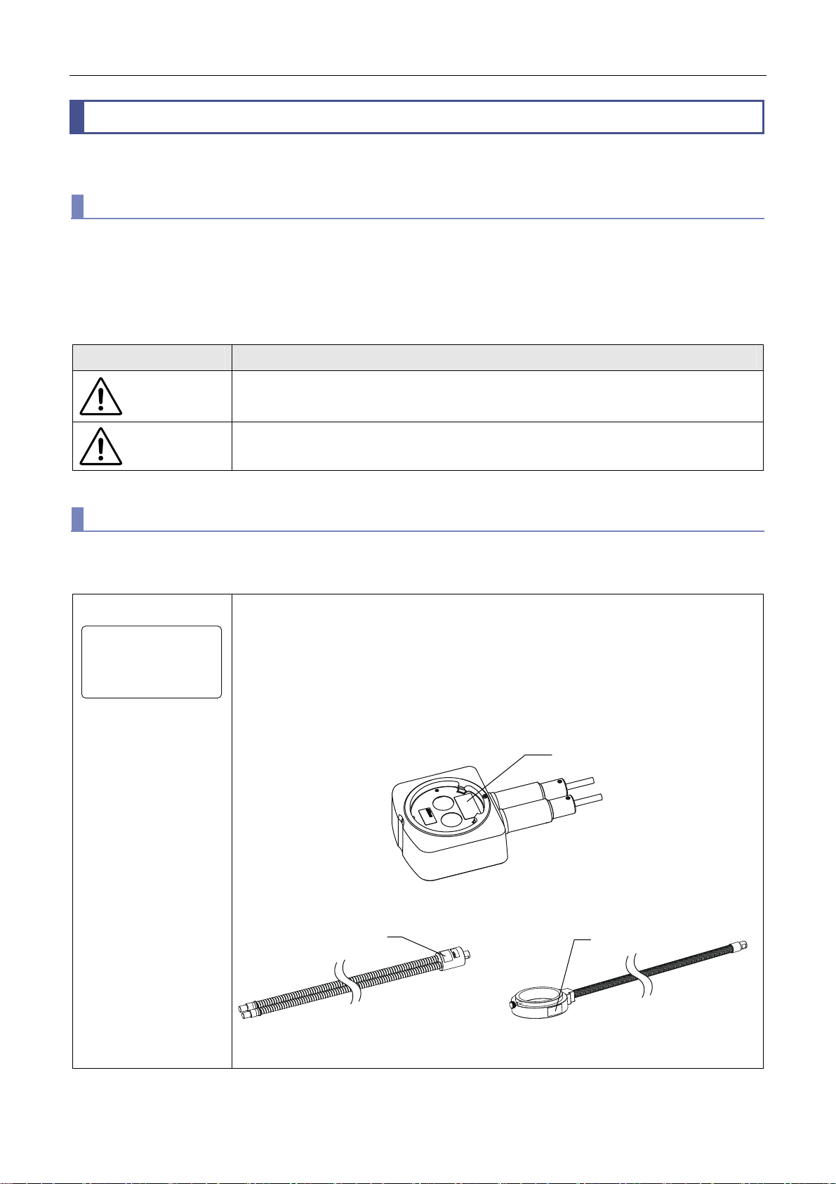
Light safety label
IEC62471 RISK GROUP2
CAUTION
Possibly hazardous optical radiation
emitted from this product.
Do not stare at operating lamp.
May be harmful to the eyes.
Caution: Do not look into the LED light.
Possibly hazardous optical radiation emitted from this product.
Do not stare at operating lamp.
May be harmful to the eyes.
RISK GROUP 2 IEC62471: 2006
Label Position
Light safety label
Light safety label
C-FDF Flexible Double Arm Fiber
Illumination Unit
P2-CI Coaxial Epi Illuminator
Light safety label
P2-FIR Ring Fiber Illumination Unit
vi
Page 9
Safety Precautions
O
Heat warning label
Light leakage
warning label
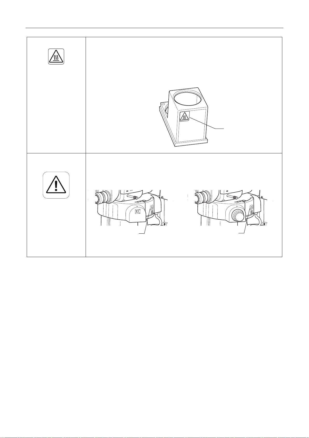
Caution: Heat of the empty cube
Immediately after diascopic observation using an epi-fluorescence attachment, the front face
of the empty cube may become hot, resulting in burns. Do not touch the front face of the
empty cube. Replace the empty cube several minutes after finishing the diascopic
observation.
Label Position
Heat warning label
Caution: Light leakage
Do not use the epi-fluorescence attachment while the filter cube replacement cover is open.
Harmful light including ultraviolet light may leak and affect fluorescence observation.
Label Position
PHOT
1
2
P2-EFLM Motorized Epi Fluorescence P2-EFLI Epi Fluorescence
Attachment Attachment
Light leakage
warning label
Light leakage
warning label
vii
Page 10

Safety Precautions
WARNING
1 Do not disassemble.
Disassembling this product may result in electric
shock or malfunction. Malfunction and damage due
to disassembling or modification are unwarranted.
Do not disassemble parts other than those
described in this manual. If you experience
problems with this product, contact your nearest
Nikon representative.
2 Read the instruction manuals carefully.
To ensure safety, carefully read this manual and the
manuals for other equipment to be used with this
product. Particularly, all warnings and cautions
given at the beginning of each manual must be
observed.
Safety is a top design priority for Nikon products.
Safety is ensured as long as the user observes all
of the warnings and cautions given in the manuals,
and uses the system only for its intended purpose.
However, failure to heed the warnings and cautions
given in the manuals, subjecting the system to
shock or impact, or attempting to disassemble the
system may result in unexpected accidents and
injury.
Product with an epi-fluorescence attachment:
The light source used for Epi-fluorescence
microscopy (HG Precentered Fiber Illuminator)
requires special care during handling because of its
characteristics.
Be sure to refer to the manual for the light source
being used.
5 Heat from the illuminator
During and immediately after a period of
illumination, the lamp and surrounding areas
(including the lamp house) are very hot if the light
source of the illumination device is a mercury lamp.
● Do not touch the lamp or surrounding areas
during or immediately after a period of
illumination. There is a risk of burn if you touch
the hot area.
● Always attach the lamp house cover when using
this product.
● Make sure the lamp and surrounding areas have
cooled sufficiently (which may take
approximately 30 minutes) before attempting to
replace the lamp.
● Do not place fabric, paper, or highly flammable
volatile materials (i.e. gasoline, petroleum
benzene, paint thinner, and alcohol) near the
lamp house while the lamp is on or for about
thirty minutes after it was turned off. Because
the lamp is very hot, ignition or fire may be
induced.
3 Checking the input rating
For a device which uses a power supply, check that
the input rating of the device matches the power
supply to be used. If the input rating does not
match, do not use the power supply and contact
your local representative. Using the device with the
power supply can cause the device to be damaged.
4 Notes on the power cord
Be sure to use the specified power cord. Use of
other power cords may result in malfunction or fire.
This product is classified as having Class I
protection against electric shock. Make sure this
product is connected to an appropriate protective
earth terminal.
See Chapter 8, “2 Performance Properties” for the
specified power cords.
● To prevent electric shock, always turn off the
power switch (Press to the “O” position.) for the
device before connecting or disconnecting the
power cord.
viii
Page 11

Safety Precautions
WARNING
6 Hazards of mercury lamps
(when using the epi-fluorescence attachment)
The light source used with the epi-fluorescence
attachment (HG Precentered Fiber Illuminator)
requires special care during handling because of its
characteristics. For safe and correct use of this
system, carefully read the warnings below. Keep in
mind all potential hazards. Additionally, carefully
read the manual for the illuminator and the manual
from the lamp manufacturer (if provided), then
follow the instructions given therein. Failure to heed
the warnings and cautions given in the manuals,
subjecting the system to shock or impact, or
attempting to disassemble the system may result in
unexpected accidents and injury.
● Ultraviolet light
When lit, mercury lamps radiate ultraviolet light
that can damage the eyes and skin. Do not
directly look at the light of the lamp. Doing so
may cause your eyesight to be lost.
When changing filter cubes, always turn off the
light source. Leaving the lamp turned on during
filter cube replacement may result in ultraviolet
exposure.
● High-pressure gas
The lamps contain sealed gas under very high
pressure. And the pressure increases when the
lamp is on. Crack or dirt of the lamp tube, strong
external force or impact, or use beyond the
tube’s life may cause the encapsulated gas to
leak or the lamp to blow up. If this happens, an
accident such as gas inhalation or injury with
glass may take place.
● Heat
When the lamp is lit, the lamp and surroundings
will become extremely hot. Do not touch the
lamp with bare hands or place flammable
materials near the lamp. Failure to comply may
result in burns or fire.
7 Hazardous sample handling
This product can also be used for microscopy and
imaging of biological samples (cells/tissues) in a
petri dish.
Check to determine whether a sample is hazardous
before handling. If the sample is hazardous, handle
it in accordance with the standard procedure
specified for your laboratory. If the sample is
potentially infectious, wear rubber gloves and avoid
direct contact with the samples. If such a sample is
spilled onto this product, the portion must be
decontaminated in a safety manner. Consult your
safety supervisor or safety standard of your facility.
● Designated lamp
Be sure to use the designated lamp. Using other
types of lamps may result in accidents, including
bursting of the lamp.
ix
Page 12

Safety Precautions
CAUTION
1 Power shutdown
To prevent electric shock and/or malfunction,
always turn off the power switch(es) for this product
and the peripheral devices (press to the “O”
position) and unplug the power cord from the wall
outlet before assembling this product, connecting
or disconnecting cables, replacing lamps, or
cleaning the zooming body and the objective.
2 Do not look into the LED light
The P2-CI Coaxial Epi Illuminator, C-FDF Flexible
Double Arm Fiber Illumination Unit and P2-FIR
Ring Fiber Illumination Unit use LEDs as the light
source. A label indicating light safety is attached to
these devices in order to pay attention to the
following. (For details about the label attachment
position, see “Label Attached to the Product” on
page vi.)
“Possibly hazardous optical radiation emitted from
this product. Do not stare at operating lamp.
May be harmful to the eyes.
RISK GROUP 2 IEC62471: 2006”
3 Be careful of the heat of the empty cube
Immediately after diascopic observation using an
epi-fluorescence attachment, the front face of the
empty cube may become hot, resulting in burns. Do
not touch the front face of the empty cube. Replace
the empty cube several minutes after diascopic
observation.
4 Caution on light leakage
Do not use the epi-fluorescence attachment while
the filter cube replacement cover is open. Harmful
light including ultraviolet light may leak and affect
fluorescence observation.
5 Specification of a light source
Be sure to use the specified light source for an
illumination device. Using a light source not
specified can cause malfunction and induce an
accident. For the specified light source, see
Chapter 8, “2 Performance Properties” or the
instruction manual for the light source.
6 Movement of motorized device
The microscope system contains motorized
devices. To avoid accidental injury by the
movements of the motorized devices, be careful
with the following when controlling the movements
of motorized device with remote controls or
personal computers.
● Before operation, check the state of the entire
microscope system to ensure safety when
operating the motorized devices.
● If having touched the zooming body, focus knob,
objective, stage, or devices or samples placed
on the stage, your hand or fingers may be
caught and injured. Before starting to operate,
keep your hands away from these items.
7 Avoid contact with water or chemical solutions.
Never expose this product to water or chemical
solutions, and avoid using this product in
circumstances where there is risk of exposure to
water or chemical solutions. Exposure of electric
parts (such as the HG Precentered Fiber
Illuminator) to liquids may cause a short circuit,
resulting in malfunction or abnormal heating. If
water or a chemical solution is splashed onto a
device, immediately turn off the power switch for
the device (press to the “O” position) and remove
the power cord from the receptacle. Then wipe off
moisture with a piece of dry cloth or something
similar. If water or a chemical solution enters this
product, stop using the product, and contact your
nearest Nikon representative.
8 Remove any covers from the product before
switching on.
Do not use a device while it is covered with a piece
of cloth, etc., Especially for a light source, which is
heated, the disturbance of heat release may cause
abnormal heat generation, inducing ignition or fire.
Do not cover the device with a piece of cloth or
similar while in use.
9 Notes on laying cables
Connect and route the cables in accordance with
the specified methods. If not connecting and
routing the cables properly, the devices may not
function correctly.
10 Do not place any object on top of the product.
Do not place any object on top of this product.
11 Cautions on assembling and installing the
product
● Take care to avoid pinching your fingers or
hands during product assembly and installation.
● Scratches or fouling optical components (such
as lens and filters) with fingerprints, etc. will
degrade microscope images. Be careful to avoid
scratches or direct contact with the lens and
filters when assembling.
x
Page 13

Safety Precautions
r
CAUTION
● The total weight of the microscope system is ove
20 kg. When moving the system to another
location, separate the removable devices
temporarily and carry the system while firmly
holding the hand holding portions of the base,
with multiple persons. Do not lift the system
while holding the binocular part of the tube or
putting hands under the objective.
● Do not place this product in a locker or cabinet.
12 Cautions on sustained observations
To relieve fatigue resulting from long observation
sessions, limit continuous observations to one
hour. Take at least 10 to 15-minute breaks between
observation sessions. Adjust the layout of other
equipment used and the height of your chair.
13 Cautions on use, transportation, and storage
This product must be operated, transported, or
stored in accordance with the following conditions.
If you install the product at a location with high
temperature and high humidity, mold and/or
condensation may be generated on the lenses.
Furthermore, performance deterioration and
malfunction may be resulted.
● Operating conditions:
temperature: 0 to +40C, humidity:
60% RH max. (no condensation)
● Transporting/storage conditions:
temperature: -20 to +60C,
humidity: 90% RH max. (no
condensation)
14 Cautions on the disposal of the product
When disposing of this product, follow the rules of
the facility.
xi
Page 14

Notes on Handling the Product
1 Handle the product carefully.
This product is a precision instrument. Avoid
subjecting it to sudden impacts and shocks.
Even relatively minor impacts are capable of affecting
the precision of the objective.
2 Scratches, dirt, and foreign particles on the lens
Scratches or fouling optical components (such as
lens and filters) with fingerprints, etc. will degrade
microscope images.
If these parts become dirty, clean them as described
in Chapter 7, “1.1 Cleaning Lenses.”
3 Installation location
This product is a precision instrument. Usage or
storage of this product in an inappropriate
environment may result in malfunction or a
degradation in precision. Consider the following
factors when selecting an installation location:
● Select a location free of vibration. Install this
product on a level surface.
● Install this product at least 10 cm away from walls.
● Select a location less exposed to hazards in the
event of collisions, earthquakes, or other potential
disasters. To keep this product from falling, use a
strong rope or other means if necessary to secure
it to the working desk or other heavy, stable item.
● Select a layout that allows easy removal of the
power cord from the device’s AC inlet in the event
of an emergency.
● Do not use a desk mat or similar.
● Avoid locations exposed to direct sunlight,
locations immediately under room lights, and other
bright locations.
● Light from room lights just above this product may
enter the objective as extraneous light. If possible,
switch off the room lights directly above this
product when making observations.
● Select a location with minimal dust.
● To avoid splashes, do not use this product near
water.
● Make sure the ambient temperature is 0 to + 40C
and humidity is 60% or less. When transporting or
storing this product, the ambient temperature must
be -20 to +60C, with the humidity at 90% RH max
(with no condensation). If you install the product at
a location with high temperature and high humidity,
mold and/or condensation may be generated on
the lenses. Furthermore, performance
deterioration and malfunction may be resulted.
● Do not place this product in a locker or cabinet.
Notes on Handling the Product
4 Handling a focus knob
● Never turn the focus knobs in opposite directions
at the same time. Doing so may damage the
product.
5 Protect the ports from dust and extraneous light
If not using the vertical tube of the trinocular tube, be
sure to attach the supplied cap. Otherwise,
extraneous light and dust may be trapped inside the
product.
6 Handling of filters (when using the
epi-fluorescence attachment)
● Excitation filters inside a filter cube are exposed to
strong light and degrade over time. Replace them
after the appropriate number of hours of use.
● Filter characteristics may alter if the filter is
exposed to high humidity. To prevent changes or
degradation of filter characteristics, avoid using or
storing the filters under conditions of high humidity
or high temperature. Avoid subjecting filters to
rapid temperature changes. When a filter is not in
use, store in a desiccator or hermetically sealed
container with a drying agent.
● Especially the filters in GFP type filter cubes offer
sharp, high-resolution waveform characteristics
superior to normal filters. However, due to their
sophisticated coatings, they must be handled with
special care. Be sure to handle the filters carefully.
Take care to avoid abrasion from cleaning. Follow
the description in Chapter 7, “1.1 Cleaning
Lenses.”
7 Motorized devices
When using motorized devices, do not force the
motorized devices to move/stop by hand.
xii
Page 15

Chapter
1
Components
In the stereo microscopes SMZ25 and SMZ18, the SMZ25 Zooming Body or SMZ18 Zooming Body is attached to a
motorized or manual focus mount. In addition, arbitrary models can be selected and combined from such device models as
bases, objectives, tubes and episcopic illuminators.
This chapter introduces the names of the devices and operation sections with the following three types of system
configuration as examples.
1 Microscopy system under episcopic illumination with an SMZ18 Zooming Body
2 Microscopy system under diascopic illumination and epi-fluorescence illumination with an SMZ25 Zooming Body
3 Compact system with an SMZ18 Zooming Body
For details about the overall system configuration, see Chapter 5, “1 System Configuration.”
1
Page 16
1
r
x
y
r
g
r
t
r
A
1.1
Trinocular Tiltin
Chapter 1 Components
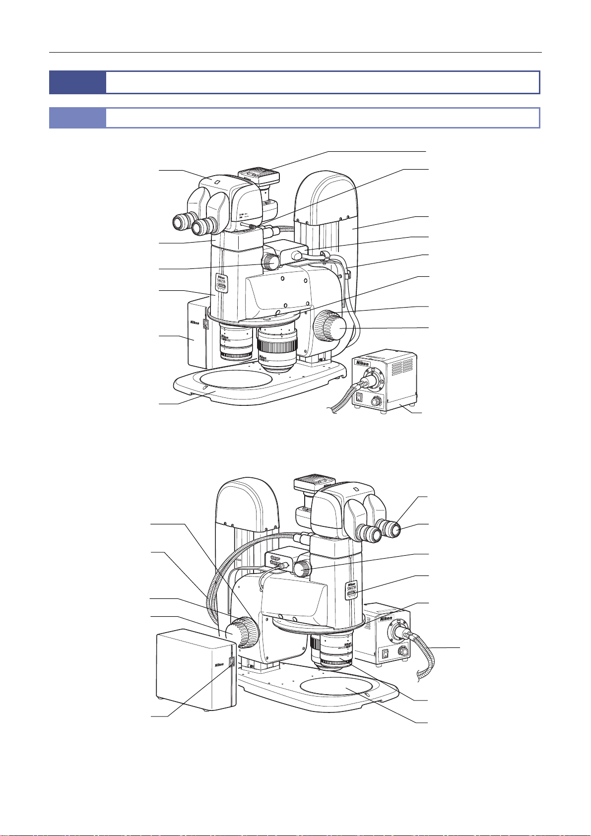
Microscopy System under Episcopic Illumination
Names of the Devices and Operation Sections
P2-TERG 100
Tube
DS camera head
Optical path switching leve
P2-FU Focus Unit
P2-CI Coaxial Epi
Illuminato
Zooming knob
SMZ18 Zooming Bod
P2-CTLB Control Bo
P2-PB Plain Base
Focus knob torque
adjustment ring
P2-RLY Relay Box
(To P2-CTLB Control Box)
P2-RNI2
Intelligent Nosepiece
Coarse focus knob
Fine focus knob
C-FLED2 LED Light Source
for Fiber Illuminator
(See the instruction manual
for the LED light source for
fiber illuminator.)
Diopter adjustment ring
Eyepiece
(to C-FLED2 LED Ligh
Fibe
Source for Fibe
Illuminator)
Coarse focus knob
Fine focus knob
M
A
E
B
T
C
O
x
U
T
a
D
N
M
I
O
N
W
R
E
m
O
m
I
P
n
R
0
0
T
1
3
A
0
D
A
0
T
:
7
I
0
-
E
t
S
2
D
0
L
u
0
:
A
p
T
4
t
2
1
R
u
:
O
o
5
S
N
h
D
2
t
S
m
8
g
E
u
A
O
0
n
L
6
L
D
le
im
C
x
e
C
E
v
a
I
a
M
W
Zooming knob
perture diaphragm dial
Nosepiece
Fiber
(from the P2-CI
Coaxial Epi
Illuminator)
Objective
Power switch
Stage plate
For the names of the components needed for assembly and connections such as the fixing screws and connectors, see
Chapter 5, “3 Assembly Procedures.”
2
Page 17
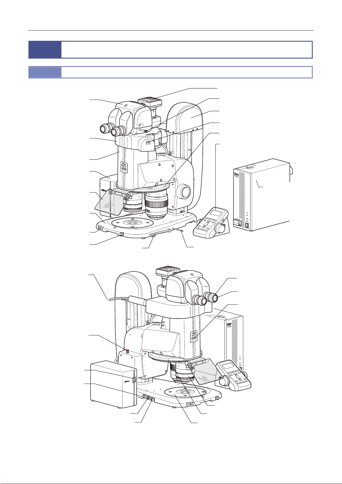
2
x
y
t
r
r
t
A
2.1
P2-TERG 100
Trinocular Tilting Tube
Chapter 1 Components
Microscopy System under Diascopic Illumination and Epi-fluorescence Illumination
Names of the Devices and Operation Sections
DS camera head
Optical path switching lever
P2-MFU Motorized Focus Unit
Turret address check window
P2-EFLM Motorized
Epi Fluorescence
Attachmen
SMZ25 Zooming Bod
P2-CTLA Control Bo
Light shielding plate
P2-DBL LED Diascopic
Illumination Base
LED power source
ON/OFF switch
LED brightness control
dial
HG fibe
(to the HG precentered
fiber illuminator)
OCC adjustmen
knob
P2-RNI2 Intelligent Nosepiece
P2-RC Remote Controller
(See “2.2 Buttons on the
P2-RC Remote Controller.”)
C-HGFIE HG
precentered fiber
illuminator
(See the instruction
manual for the HG
precentered fiber
illuminator.)
Prism sheet IN/OUT lever
Diopter adjustment ring
Eyepiece
perture diaphragm dial
STOP switch
Power switch
AC adapte
input terminal
Objective
LED brightness control terminal
LED brightness control selection switch
Nosepiece
Stage plate
For the names of the components needed for assembly and connections such as the fixing screws and connectors, see
Chapter 5, “3 Assembly Procedures.”
3
Page 18
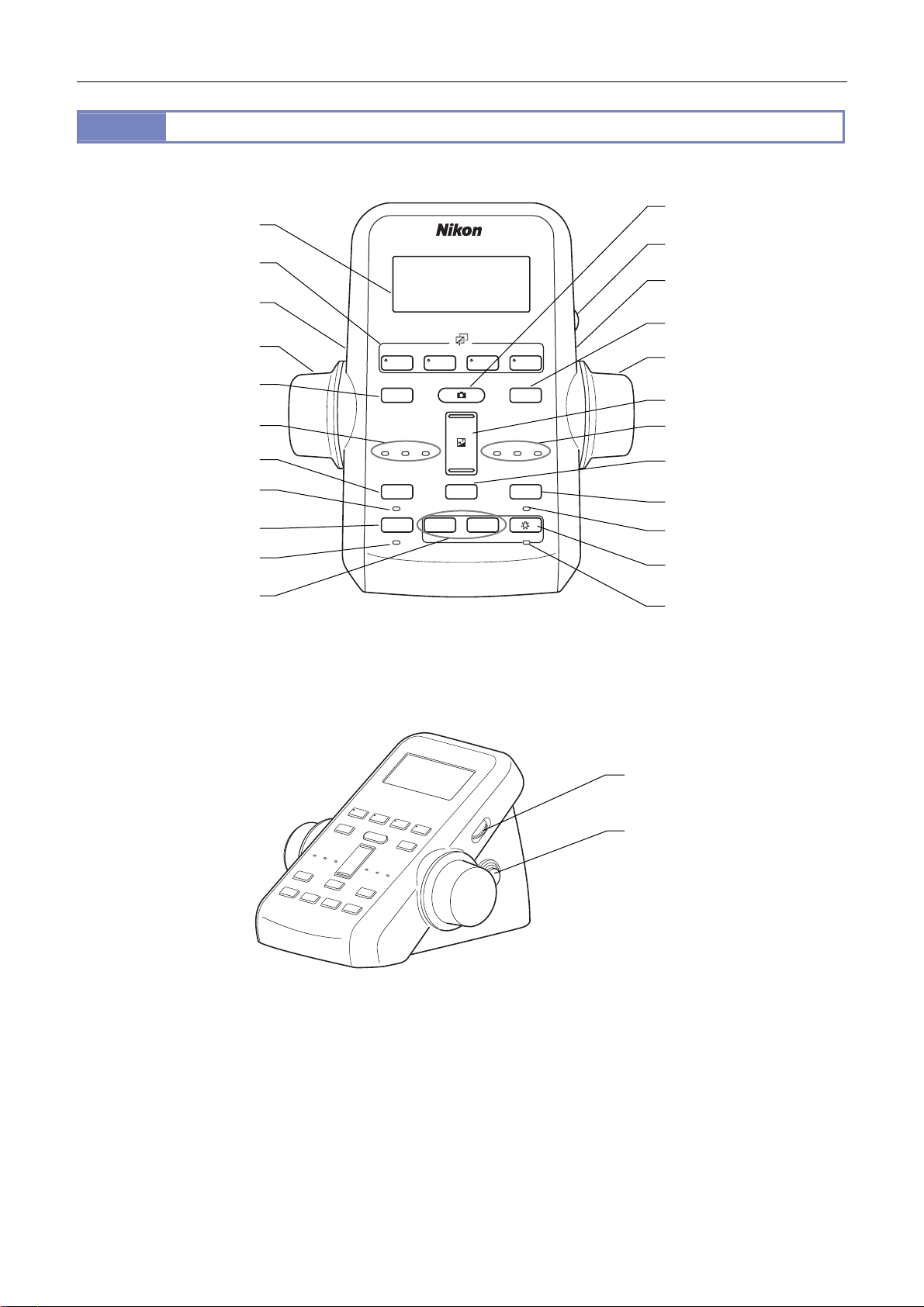
2.2
1 2 3 4
DISPLAY
BRIGHTNESS
ESCAPE
ALZ
LIMIT
ZOOM
STEP
Z-RESET
Z-SPEED
ZOOM STEP
Coarse
FL Cube
ON/OFF
ON/OFF
ON/OFF
ON/OFF
Fine
Ex Fine
0.5x
0.1x
r
r
r
r
r
(6) Filter cube switching
(4) Fine/coarse focus
switching button
(3) Focus knob
Chapter 1 Components
Buttons on the P2-RC Remote Controller
(1) LCD
button
FL Cube
BRIGHTNESS
(9) Capture button
(2) Backlight control dial
(4) Fine/coarse focus
switching button
(8) Z-reset button
(3) Focus knob
(7) LCD display switching
(5) Focus speed indicato
(13) Escape button
(14) Escape ON/OFF
(17) ALZ button
(18) ALZ ON/OFF
(19) Diascopic LED
brightness control button
button
indicato
indicato
Coarse
DISPLAY
Z-SPEED
ESCAPE
ON/OFF
ALZ
ON/OFF
Fine
Ex Fine
−+
+
−
ZOOM
STEP
ZOOM STEP
1x1x0.5x
Z-RESET
LIMIT
ON/OFF
ON/OFF
(10) Zoom button
(12) Zoom step indicato
0.1x
(11) Zoom step switching
button
(15) Limit button
(16) Limit ON/OFF indicato
(20) Diascopic LED ON/OFF
button
(21) Diascopic LED ON/OFF
indicator
(2) Backlight control dial
(4) Fine/coarse focus
switching button
(on both sides)
Front Right Side
For details about the buttons’ functions, see “Functions and indications of the operation buttons” in Chapter 4, “10.1 P2-RC
Remote Controller.”
4
Page 19
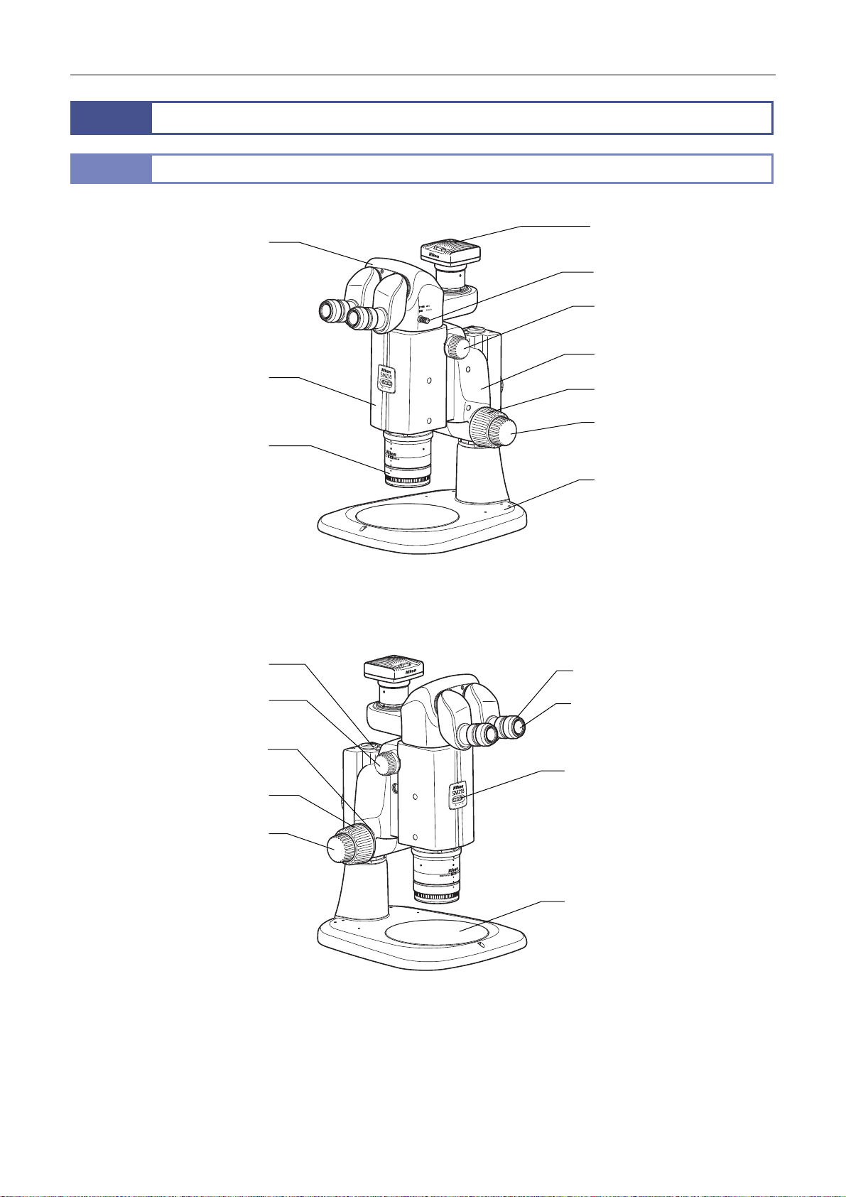
3
r
y
L
A
3.1
P2-TL100 Trinocular Tube
SMZ18 Zooming Bod
Chapter 1 Components
Compact System
Names of the Devices and Operation Sections
DS camera head
Optical path switching leve
Zooming knob
P2-FMDN Focus Mount
Coarse focus knob
Fine focus knob
Objective
P-PS32 Plain Stand
Clamp tool
Zooming knob
Focus knob torque
adjustment ring
Coarse focus knob
Fine focus knob
Diopter adjustment ring
Eyepiece
perture diaphragm dial
Stage plate
For the names of the components needed for assembly and connections such as the fixing screws and connectors, see
Chapter 5, “3 Assembly Procedures.”
5
Page 20

Chapter 1 Components
☆☆☆
6
Page 21

Chapter
2
Microscopy Procedures
This chapter describes the microscopy procedures listed below.
The devices used in the descriptions are based on the configuration examples given in the previous chapter.
Procedure 1: Procedure for microscopy under episcopic illumination
Procedure 2: Procedure for microscopy under diascopic illumination
Procedure 3: Procedure for epi-fluorescence microscopy
It is assumed that all required components are attached to the microscope with all necessary cables properly connected.
If assembly of the microscopy system has not yet been completed, complete assembly as described in Chapter 5, “3
Assembly Procedures.”
When using the motorized system or intelligent system for microscopy, see Chapter 3, “16 Internally Saved Information.”
7
Page 22
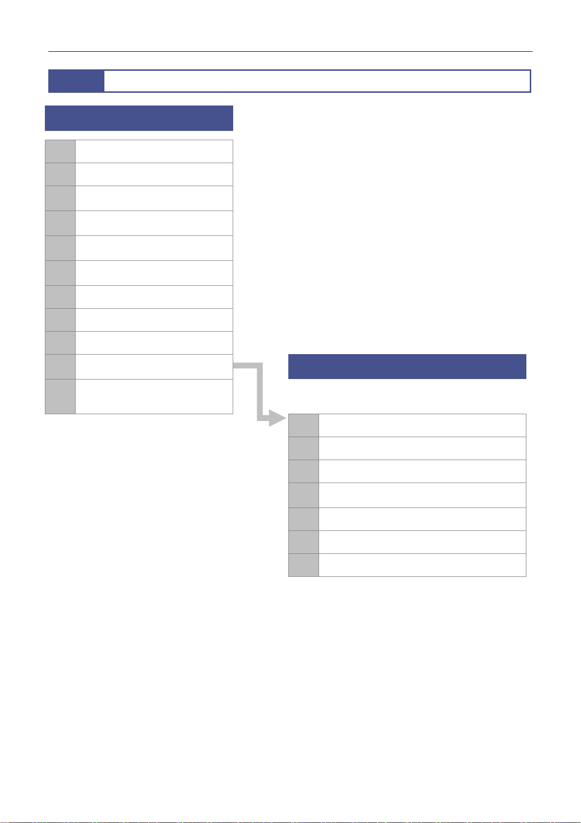
Chapter 2 Microscopy Procedures
1
Microscopy under episcopic illumination or
Turn on the power.
1
Set a sample.
2
Bring an objective into the optical
3
path.
Turn on the illumination and adjust
4
the brightness.
Set the optical path to 100% to the
5
binocular part.
Adjust the depression angle of the
6
tilting tube.
Adjust the diopter.
7
Adjust the interpupillary.
8
Operation Flowchart
diascopic illumination
Adjust the focus.
9
Change the magnification using the
10
zooming knobs.
Turn off the power after completing
11
microscopy.
* In microscopy under diascopic
illumination using an epi-fluorescence
attachment, attach an empty cube
(supplied with the microscope) to the
epi-fluorescence attachment and bring it
into the optical path.
* In a compact system of an SMZ18
Zooming Body combined with a P-PS32
Plain Stand and P2-FMDN Focus Mount,
perform the steps above in the order of [2],
[5], [6], [7], [8], [9], and [10].
11
12
13
14
15
16
17
Epi-fluorescence microscopy
After locating the target in the sample with
microscopy under diascopic illumination, follow
the procedure below:
Turn off the diascopic LED illumination.
Bring the filter cube into the optical path.
Adjust the angle of the light shielding plate.
Turn on the HG precentered fiber illuminator and
adjust the brightness.
Adjust the focus.
Change the magnification by zooming in and out.
Turn off the power after completing microscopy.
8
Page 23
Chapter 2 Microscopy Procedures
2
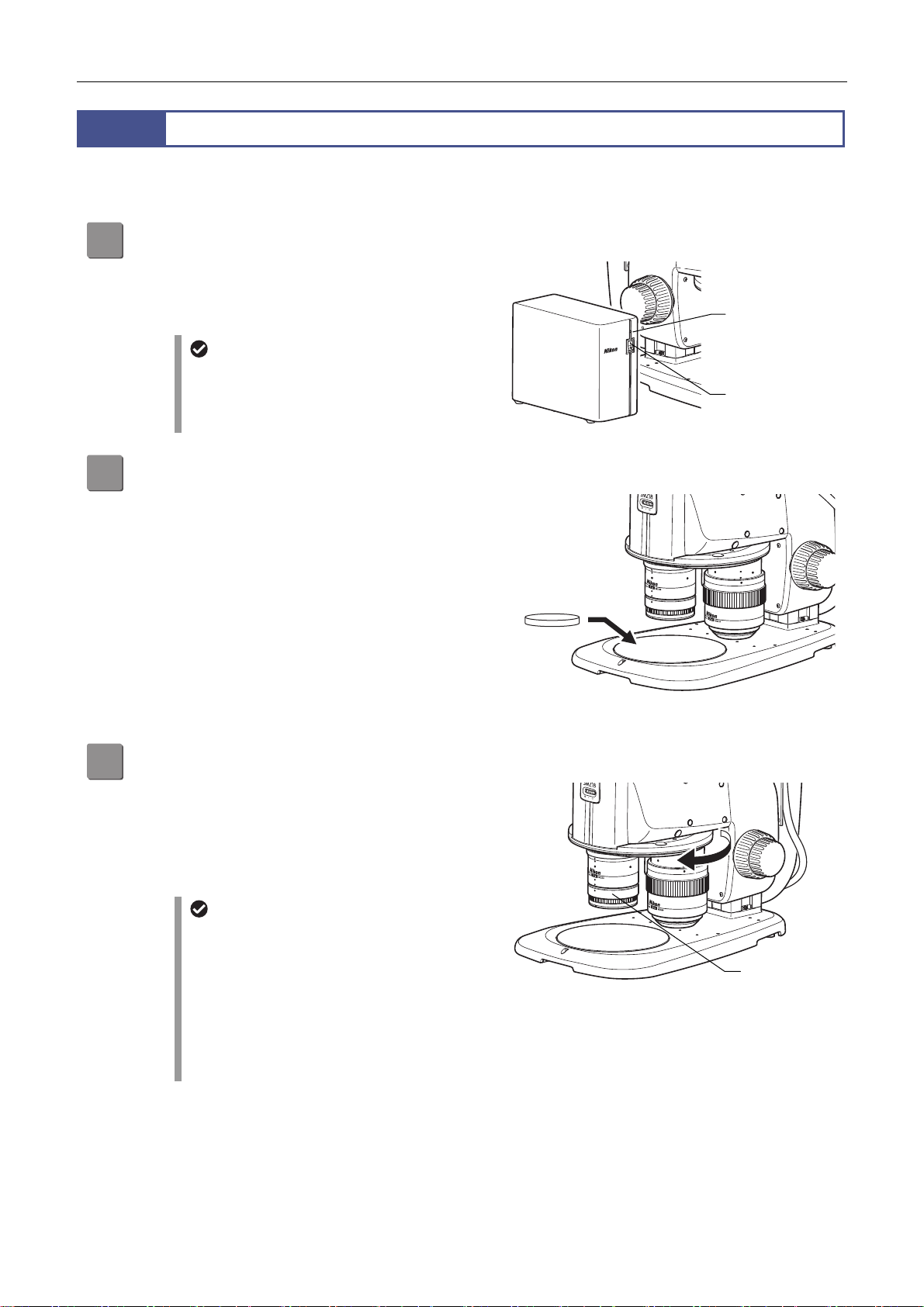
This section describes the procedure for performing microscopy under episcopic illumination using the SMZ18 Zooming
Body combined with the P2-CI Coaxial Epi Illuminator.
Procedure for Microscopy under Episcopic Illumination
Turn on the power.
1
Turn on the P2-CTLB Control Box by pressing the power
switch to the “|” position.
Check that the power LED on the control box lights.
Set a sample.
2
Place a sample on the stage plate and immediately under
the objective.
Power supply to the DS-L3 DS Camera
Control Unit
When the DS-L3 DS Camera Control Unit is
connected, turn on the control box and then the
DS-L3.
Sample
Power LED: On
Power switch: “|”
position
Power on
Bring an objective into the optical path.
3
Turn the nosepiece to bring the objective to be used into
the optical path.
Check that the objective falls into the click position when
turning the nosepiece.
(See Chapter 3, “8.2 Switching Objectives.”)
P2-CI Coaxial Epi Illuminator
The P2-CI Coaxial Epi Illuminator is supplied
with a 1/4 lambda plate. When using the 0.5x or
1x objective, attach the 1/4 lambda plate to the
tip of the objective. Turn the 1/4 lambda plate so
that the white circle (indicator) is at the front.
For the P2-CI Coaxial Epi Illuminator, available
objectives and zooming ratios are restricted. For
details, see Chapter 4, “7.1 P2-CI Coaxial Epi
Illuminator.”
Setting the sample
Rotating the nosepiece
Objective on
the optical path
9
Page 24
Chapter 2 Microscopy Procedures
A
A
Turn on the illumination and adjust the brightness.
4
Refer to the instruction manual for the C-FLED2 LED Light Source for Fiber Illuminator.
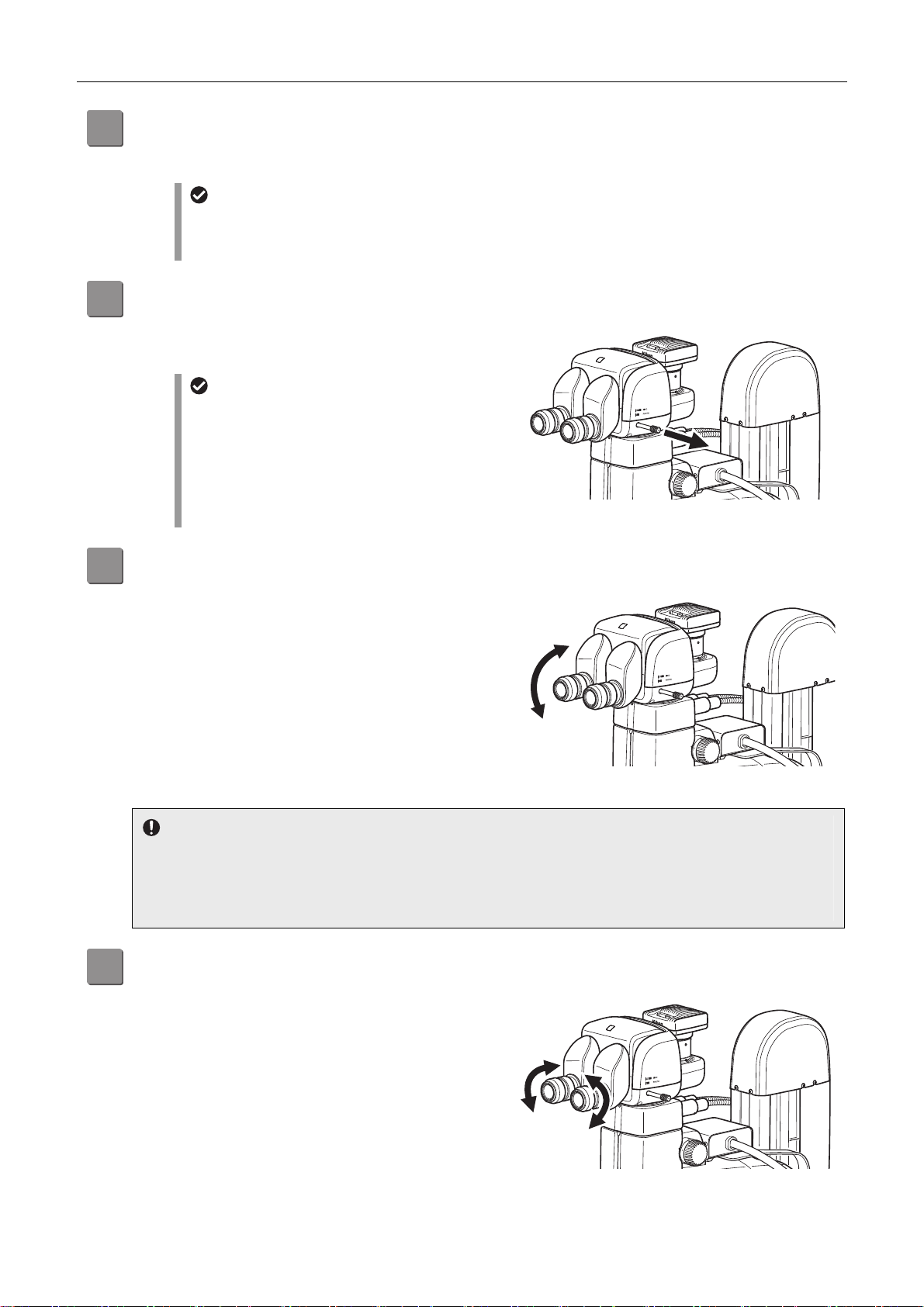
Set the optical path to 100% to the binocular part.
5
Pull out the optical path switching lever of the tube to set
the optical path to 100% to the binocular part.
Aperture diaphragm
The SMZ18 Zooming Body is equipped with an aperture diaphragm. Turn the aperture diaphragm dial
counterclockwise (Ο side) to fully open the aperture. (For details about using the aperture diaphragm, see
Chapter 3, “10 Using the Aperture Diaphragm.”)
Moving the optical path switching lever
Pulling out the optical path switching lever: 100% to
the binocular part
Pushing in the optical path switching lever: 100% to
the vertical tube
The division ratio of the light amount differs
depending on the tube types. (See Chapter 3, “3
Switching the Optical Path of the Tube.”)
Optical path to the binocular part: 100%
Adjust the depression angle of the tilting tube.
6
When using the P2-TERG 100 or P2-TERG 50 Trinocular
Tilting Tube, change and adjust the angle of the binocular
part to facilitate microscopy.
(The low eye level P2-TL100 Trinocular Tube L does not
have a mechanism for adjusting the angle of depression.)
7
Notes on adjusting the angle of depression
Do not apply excessive force to the binocular part during depression angle adjustment. It may cause unexpected
failure or malfunction.
When moving the binocular part, be careful not to catch your fingers in the rotary section at the bottom of the
binocular part.
Adjust the diopter.
djust to match your diopter. For details, see Chapter 3, “5
djusting the Diopter.”
This adjustment is required for each user.
Adjusting the angle of depression
Adjusting the diopter
10
Page 25
Chapter 2 Microscopy Procedures
A
A
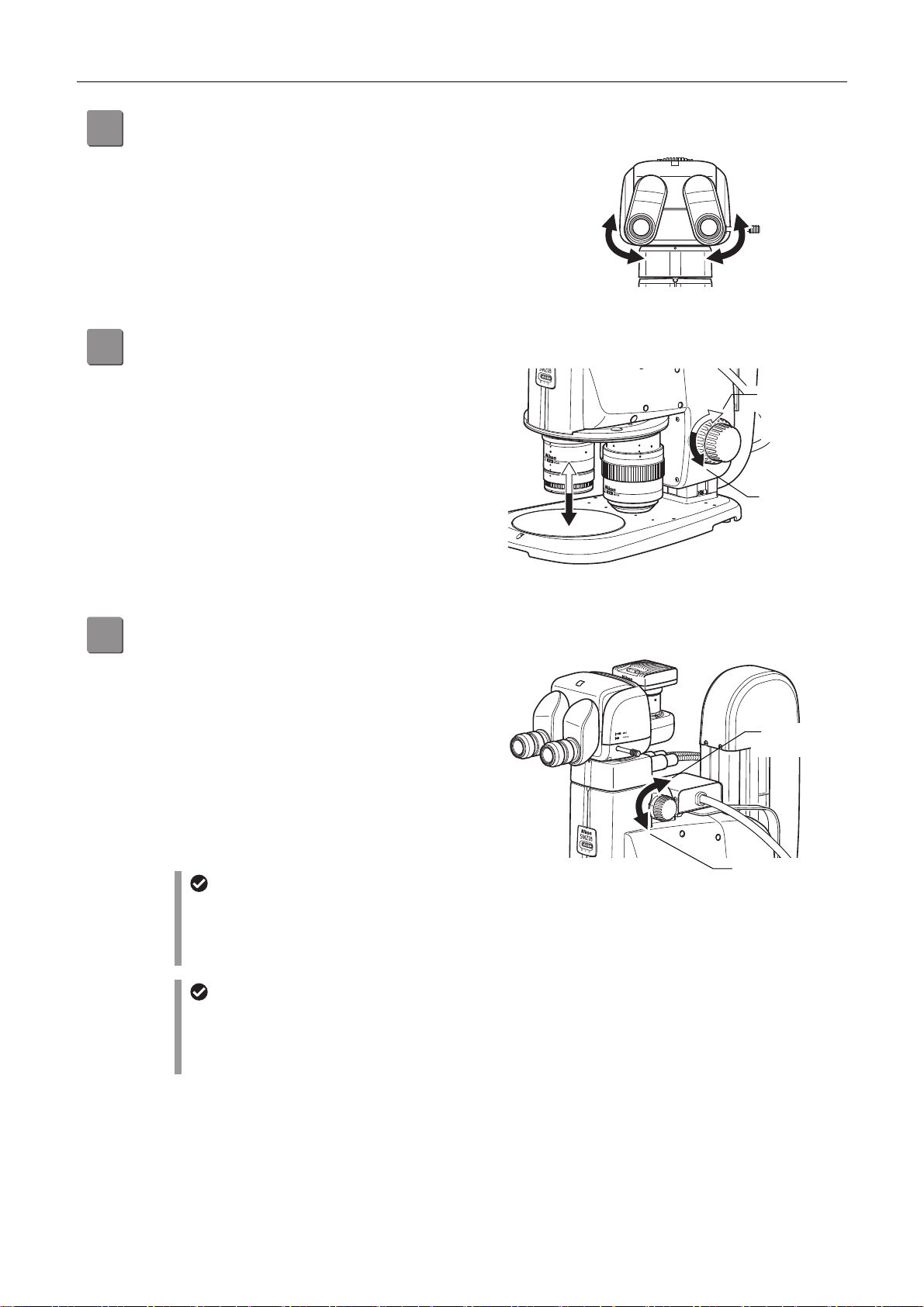
Adjust the interpupillary.
8
djust to match the distance between your right and left
eyes. Look into both eyepieces and move the binocular
part of the tube so that the right and left fields of view
merge into a single circle.
This adjustment is required for each user.
Adjust the focus.
9
Turn the focus knobs (coarse/fine control) on the right and
left of the focus unit to move the focus mount of the focus
unit vertically and focus on the sample. The figure shows
the turning directions of a knob and the corresponding
vertical movements of the focus mount (zooming body).
Turning the knob backward: Upward movement
Turning the knob forward: Downward movement
(See Chapter 3, “7 Focusing on the Sample.”)
djusting the interpupillary distance
Upward
movement
Downward
movement
Focusing
Change the magnification using the zooming knobs.
10
Turn the zooming knobs on the right and left of the SMZ18
Zooming Body to change the magnification. The figure
shows the turning directions of a knob and the
corresponding changes in magnification.
Turning the knob backward: Magnification increase
Turning the knob forward: Magnification decrease
The magnification continuously changes from 0.75x to
13.5x.
Zoom magnification values are marked on the zooming
knobs.
Click stop during image zooming
It is also possible to cause a click stop to occur at
predetermined magnification positions during
image zooming.
(See Chapter 4, “1.1 SMZ18 Zooming Body.”)
P2-CI Coaxial Epi Illuminator
For the P2-CI Coaxial Epi Illuminator, available
objectives and zooming ratios are restricted. For
details, see Chapter 4, “7.1 P2-CI Coaxial Epi
Illuminator.”
Zoom operation
Magnification
increase
Magnification
decrease
11
Page 26

A
Chapter 2 Microscopy Procedures
Turn off the power after completing microscopy.
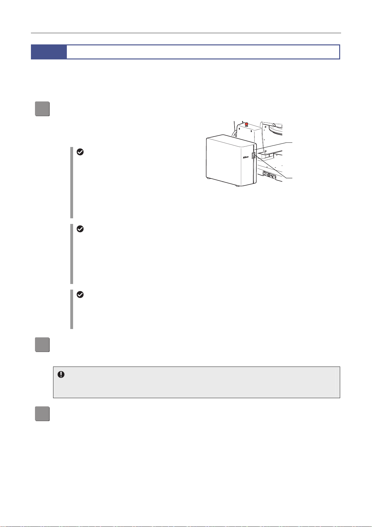
11
Turn off the P2-CTLB Control Box by pressing the power
switch to the “O” position.
Check that the power LED on the control box turns off.
lso turn off the LED light source for fiber illuminator.
Power LED: Off
Power switch: “O”
position
Power off
12
Page 27
Chapter 2 Microscopy Procedures
3
This section describes the procedure for microscopy under diascopic illumination using the SMZ25 Zooming Body combined
with the P2-DBL LED Diascopic Illumination Base.
For the same operations as in “2 Procedure for Microscopy under Episcopic Illumination,” details are omitted.
Procedure for Microscopy under Diascopic Illumination
Turn on the power.
1
Turn on the P2-CTLA Control Box by pressing the power
switch to the “|” position.
Check that the power LED on the control box lights.
P2-MFU Motorized Focus Unit
When the power is turned on, the motorized focus
unit is initialized as follows:
(1) The focus mount rises to the upper sensor
limit.
(2) This is followed by downward movement to the
position when power was turned on.
* Other motorized devices also perform internal
initialization.
Power supply to the P2-DBL LED
Diascopic Illumination Base
For a system configuration where a control box has
been connected, the control box supplies power to
the P2-DBL LED Diascopic Illumination Base. The
P2-DBL therefore need not be connected to a
power supply. (See Chapter 4, “8.1 P2-DBL LED
Diascopic Illumination Base.”)
Power supply to the DS-L3 DS Camera
Control Unit
When the DS-L3 DS Camera Control Unit is
connected, turn on the control box and then the
DS-L3.
Power on
Power LED: On
Power switch: “|”
position
Set a sample.
2
→ Step 2 in “2 Procedure for Microscopy Under Episcopic Illumination”
3
→ Step 3 in “2 Procedure for Microscopy Under Episcopic Illumination”
Empty cube
When an epi-fluorescence attachment is mounted, check that the empty cube of the attachment is in the optical
path.
Bring an objective into the optical path.
13
Page 28
Chapter 2 Microscopy Procedures
1 2 3 4
DISPLAY
BRIGHTNESS
ESCAPE
ALZ
LIMIT
ZOOM
STEP
Z-RESET
Z-SPEED
ZOOM STEP
Coarse
FL Cube
ON/OFF
ON/OFF
ON/OFF
ON/OFF
Fine
Ex Fine1x1x
0.5x
0.1x
r
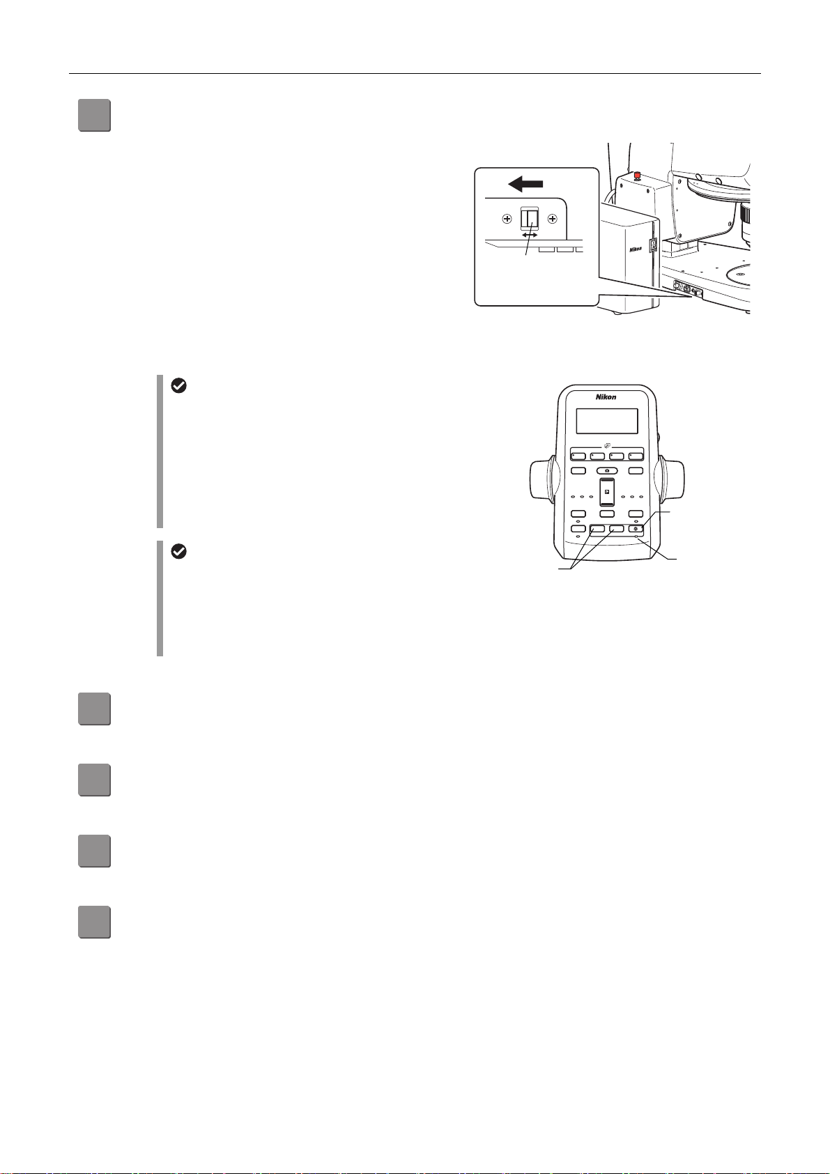
Turn on the illumination and adjust the brightness.
4
Check that the brightness control selection switch on the
LED diascopic illumination base is set to the ON position.
Press the diascopic LED ON/OFF button on the remote
controller to turn on the LED illumination.
Check that the LED ON/OFF indicator lights.
Press the diascopic LED brightness control buttons to
adjust the brightness. Press [+] to increase the brightness
and [-] to decrease the brightness.
Illumination on and brightness control
rights
To turn on the diascopic illumination and perform
brightness control directly with the LED diascopic
illumination base, set the LED brightness control
selection switch to the OFF position.
For details about using the diascopic illumination
base, see Chapter 4, “8.1 P2-DBL LED Diascopic
Illumination Base.”
Aperture diaphragm
The SMZ25 Zooming Body is equipped with an
aperture diaphragm. Turn the aperture diaphragm
dial counterclockwise (O side) to fully open the
aperture. (For details about using the aperture
diaphragm, see Chapter 3, “10 Using the Aperture
Diaphragm.”)
TRL
LED brightness
control selection
switch
Diascopic LED
brightness control
button
CTRL
ON OFF
Setting brightness control right
to the control box
Coarse
DISPLAY
Z-SPEED
ESCAPE
ON/OFF
ALZ
ON/OFF
Fine
Ex Fine
FL Cube
+
−
ZOOM
STEP
−+
ZOOM STEP
Z-RESET
0.5x
BRIGHTNESS
0.1x
LIMIT
ON/OFF
ON/OFF
Remote on/brightness control
Diascopic LED
ON/OFF button
LED ON/OFF
indicato
Set the optical path to 100% to the binocular part.
5
→ Step 5 in “2 Procedure for Microscopy Under Episcopic Illumination”
Adjust the depression angle of the tilting tube.
6
→ Step 6 in “2 Procedure for Microscopy Under Episcopic Illumination”
Adjust the diopter.
7
→ Step 7 in “2 Procedure for Microscopy Under Episcopic Illumination”
Adjust the interpupillary.
8
→ Step 8 in “2 Procedure for Microscopy Under Episcopic Illumination”
14
Page 29
Chapter 2 Microscopy Procedures
1 2 3 4
DISPLAY
BRIGHTNESS
ESCAPE
ALZ
LIMIT
ZOOM
STEP
Z-RESET
Z-SPEED
ZOOM STEP
Coarse
FL Cube
ON/OFF
ON/OFF
ON/OFF
ON/OFF
Fine
Ex Fine1x1x
0.5x
0.1x
1 2 3 4
DISPLAY
BRIGHTNESS
ESCAPE
ALZ
LIMIT
ZOOM
STEP
Z-RESET
Z-SPEED
ZOOM STEP
Coarse
FL Cube
ON/OFF
ON/OFF
ON/OFF
ON/OFF
Fine
Ex Fine1x1x
0.5x
0.1x
t
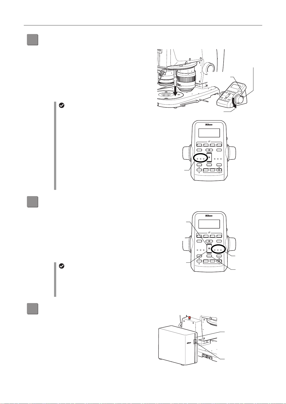
Adjust the focus.
9
Turn the focus knobs of the remote controller to move the
focus mount of the focus unit vertically and focus on the
sample. The figure shows the turning directions of a knob
and the corresponding vertical movements of the focus
mount (zooming body).
Turning the knob backward: Upward movement
Turning the knob forward: Downward movement
(See Chapter 3, “7 Focusing on the Sample.”)
Focus speed switching
The focus speed can be switched between coarse,
fine, and extra fine control.
Use the fine/coarse focus switching button on the
remote controller to switch the speed.
Each time the button is pressed, the focus speed is
cyclically switched in the order of coarse, fine, and
extra fine.
When the focus speed is changed, the
corresponding indicator (Coarse/Fine/ExFine)
lights.
Coarse: 2 to 10 mm/second
Fine: 0.2 to 5 mm/second
Focus speed
indicator
Extra fine: 0.01 to 0.1 mm/second
Upward
movement
Downward movemen
FL Cube
DISPLAY
Z-SPEED
Coarse
Fine
ESCAPE
ON/OFF
ALZ
ON/OFF
+
Ex Fine
−
ZOOM
STEP
−+
ZOOM STEP
Z-RESET
0.5x
Focus operation
Fine/coarse focus
switching button
BRIGHTNESS
0.1x
LIMIT
ON/OFF
ON/OFF
Change the magnification by zooming in and out.
10
Press the zoom buttons on the remote controller to
change the magnification of the zooming body.
Upper zoom button: Magnification increase
Lower zoom button: Magnification decrease
The magnification changes in the range from 0.63x to
Upper zoom
button
(magnification
increase)
15.75x.
Pressing and holding the buttons causes the magnification
to change continuously.
Magnification step size
Each time the zoom step switching button is pressed,
the step size changes in the following order: 1x, 0.5x
Lower zoom
button
(magnification
decrease)
then 0.1x. When a step size is selected, the
corresponding step LED indicator lights.
(See Chapter 4, “1.2 SMZ25 Zooming Body.”)
Turn off the power after completing microscopy.
11
Turn off the P2-CTLA Control Box by pressing the power
switch to the “O” position.
Check that the power LED on the control box turns off.
FL Cube
DISPLAY
Z-SPEED
Coarse
Fine
ESCAPE
ON/OFF
ALZ
ON/OFF
+
Ex Fine
−
ZOOM
STEP
−+
ZOOM STEP
Z-RESET
0.5x
0.1x
LIMIT
ON/OFF
ON/OFF
Zoom operation
BRIGHTNESS
Zoom step
indicator
Zoom step
switching
button
Power LED: Off
Power switch: “O”
position
Power off
15
Page 30
Chapter 2 Microscopy Procedures
1 2 3 4
DISPLAY
BRIGHTNESS
ESCAPE
ALZ
LIMIT
ZOOM
STEP
Z-RESET
Z-SPEED
ZOOM STEP
Coarse
FL Cube
ON/OFF
ON/OFF
ON/OFF
ON/OFF
Fine
Ex Fine1x1x
0.5x
0.1x
1 2 3 4
DISPLAY
BRIGHTNESS
ESCAPE
ALZ
LIMIT
ZOOM
STEP
Z-RESET
Z-SPEED
ZOOM STEP
Coarse
FL Cube
ON/OFF
ON/OFF
ON/OFF
ON/OFF
Fine
Ex Fine1x1x
0.5x
0.1x
r
4
After locating a target in a sample in “3 Procedure for Microscopy Under Diascopic Illumination” (steps 1 to 10), follow the
procedure below:
Procedure for Epi-fluorescence Microscopy
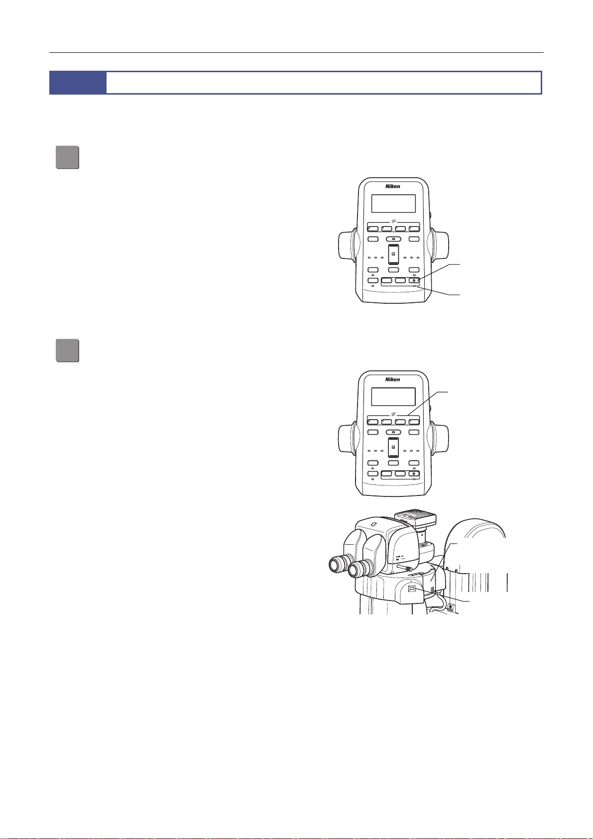
Turn off the diascopic LED illumination.
11
Press the diascopic LED ON/OFF button on the remote
controller to turn off the LED illumination.
Check that the diascopic LED ON/OFF indicator turns off.
Bring the filter cube into the optical path.
12
Press the filter cube switching buttons (FL1 to FL4) on the
remote controller to bring the desired filter cube into the
optical path. FL1 to FL4 designate the turret addresses of
the epi fluorescence attachment. The LED of the pressed
button lights so that the turret address on the optical path
can be identified. The address on the optical path can be
identified also through the turret address check window of
the epi fluorescence attachment.
ZOOM STEP
0.5x
Z-RESET
BRIGHTNESS
0.1x
LIMIT
ON/OFF
ON/OFF
Diascopic LED
ON/OFF button
Diascopic LED
ON/OFF indicato
FL Cube
DISPLAY
+
Z-SPEED
Coarse
Fine
Ex Fine
−
ZOOM
ESCAPE
STEP
ON/OFF
ALZ
−+
ON/OFF
Diascopic LED illumination off
Filter cube switching
button
ZOOM STEP
Z-RESET
0.5x
BRIGHTNESS
0.1x
LIMIT
ON/OFF
ON/OFF
FL Cube
DISPLAY
+
Z-SPEED
Coarse
Fine
Ex Fine
−
ZOOM
ESCAPE
STEP
ON/OFF
ALZ
−+
ON/OFF
16
Turret rotation in the
epi fluorescence
attachment
Bringing the filter cube into the optical path
Turret address
check window
Page 31
Chapter 2 Microscopy Procedures
A
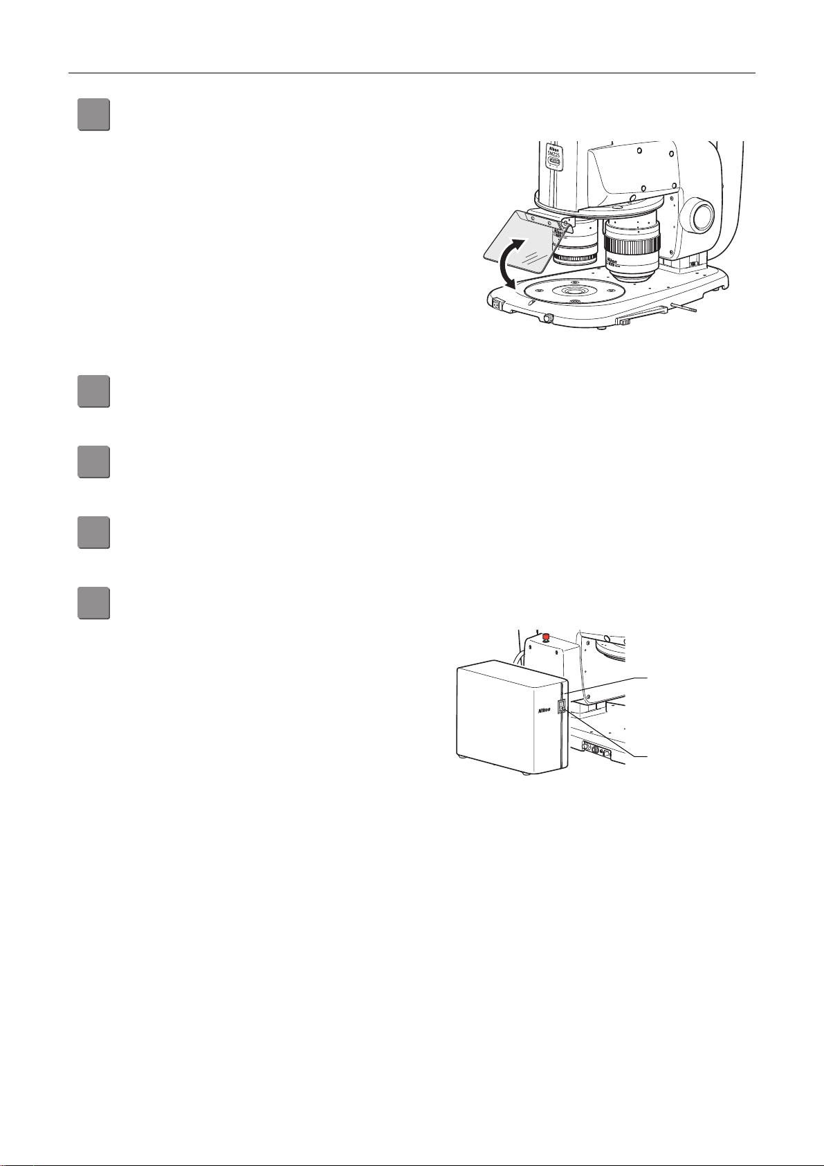
Adjust the angle of the light shielding plate.
13
Change the angle of the light shielding plate to 45° to
prevent light reflected from the objective from entering
your eyes.
Turn on the HG precentered fiber illuminator and adjust the brightness.
14
Refer to the instruction manual for the fiber light source.
Adjust the focus.
15
→ Step 9 in “3 Procedure for Microscopy Under Diascopic Illumination”
Adjusting the angle of the light shielding plate
Change the magnification by zooming in and out.
16
→ Step 10 in “3 Procedure for Microscopy Under Diascopic Illumination”
Turn off the power after completing microscopy.
17
Turn off the HG precentered fiber illuminator and P2-CTL
Control Box by pressing their power switches to the “O”
position. Check that their power LEDs go off.
Power off
Power LED: Off
Power switch: “O”
position
17
Page 32

Chapter 2 Microscopy Procedures
☆☆☆
18
Page 33

Chapter
3
Specific Operations
This chapter describes how to work with this microscope system in order to observe samples.
For details about using the individual devices, see Chapter 4.
19
Page 34
Chapter 3 Specific Operations
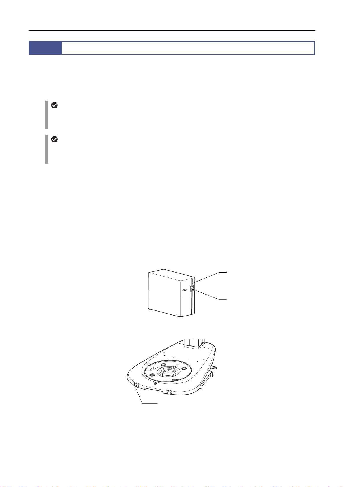
1
When using this microscope system, power to the following devices must be turned on:
P2-CTLA Control Box
P2-CTLB Control Box
P2-DBL LED Diascopic Illumination Base
P2-FIRL LED Ring Illumination Unit (See the instruction manual for the P2-FIRL LED Ring Illumination Unit.)
P-DF LED Dark Field Unit (See the instruction manual for the P-DF LED Dark Field Unit.)
When using an illuminator whose light source is an HG precentered fiber illuminator or fiber illumination LED light source,
also turn on the power to the light source. (See the instruction manual for the light source.)
When using multiple power supplies, they need not be turned on in a particular order except for the following cases:
When using a DS camera control unit to capture images, power on the DS camera control unit at the end.
When controlling a C-HGFIE HG Precentered Fiber Illuminator from NIS-Elements, etc. via a control box, power on the
HG precentered fiber illuminator before the control box.
Press the power switch to the “|” position to turn the power on and to the “O” position to turn the power off.
When power is turned on, the power LED lights.
Turning On the Power
12 V AC adapter
For a system configuration where a control box has been connected, the P2-DBL LED Diascopic Illumination Base need
not be connected to a power supply. The control box supplies the power. If a control box is not used, connect the 12 V AC
adapter to the P2-DBL.
LED power On/Off control right
If the LED brightness control selection switch on the base has been set to ON to assign the control right to the control box,
the LED power On/Off switch and LED brightness control dial on the base need not be used. They can be remotely
controlled using the remote controller connected to the control box or a personal computer (software: NIS-Elements).
Power LED (Lit: ON)
Power switch
(“|” to turn on; “O” to turn off)
Power switch of the control box
LED power On/Off switch
(“|” to turn on; “O” to turn off)
Power switch of the P2-DBL LED Diascopic Illumination Base
20
Page 35
Chapter 3 Specific Operations
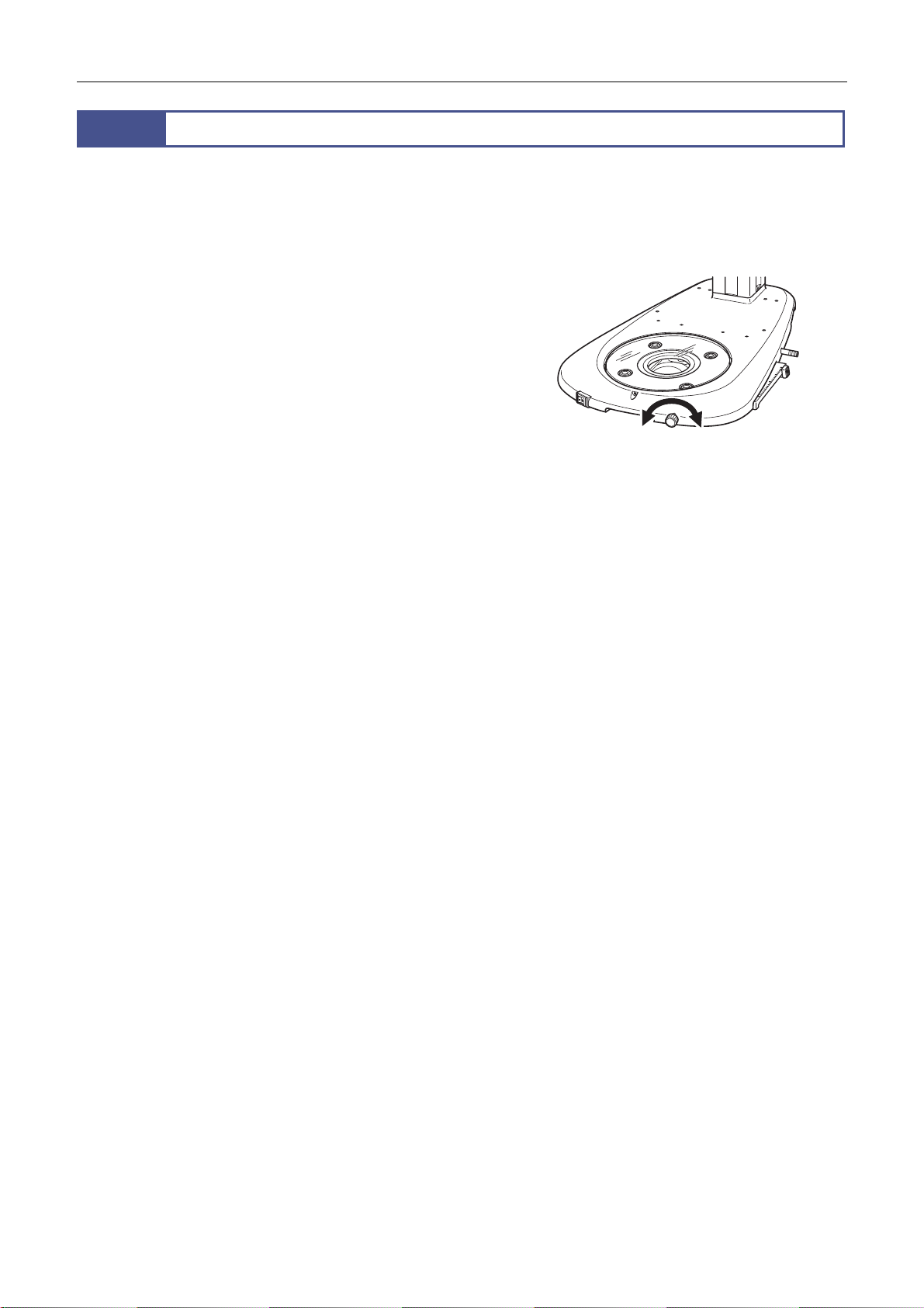
r
2
The illumination brightness can be adjusted for the following devices. Turn the brightness control dial to adjust the brightness
to a comfortable level.
Depending on the system configuration, some devices support remote control of the brightness.
For details, see the sections in Chapter 4 describing how to use the individual devices.
Adjust the brightness using the adjustment volume of the
device
P2-DBL LED Diascopic Illumination Base
Adjust the brightness using the C-FLED2 LED Light source fo
fiber illuminator
(See the instruction manual supplied with the C-FLED2 for
details.)
P2-CI Coaxial Epi Illuminator
C-FDF Flexible Double Arm Fiber Illumination Unit
P2-FIR Ring Fiber Illumination Unit
P2-DBF Fiber Diascopic Illumination Base
Adjusting the Brightness
Adjusting the diascopic illumination brightness
Adjust the brightness using the C-HGFI/C-HGFIE HG
Precentered Fiber Illuminator
(See the instruction manual supplied with the
C-HGFI/C-HGFIE for details.)
P2-EFLI Epi Fluorescence Attachment
P2-EFLM Motorized Epi Fluorescence Attachment
Adjust the brightness using the power supply section of each
unit
(See the instruction manual supplied with the P2-FIRL/P-DF
for details.)
P2-FIRL LED Ring Illumination Unit
P-DF LED Dark Field Unit
21
Page 36
Chapter 3 Specific Operations
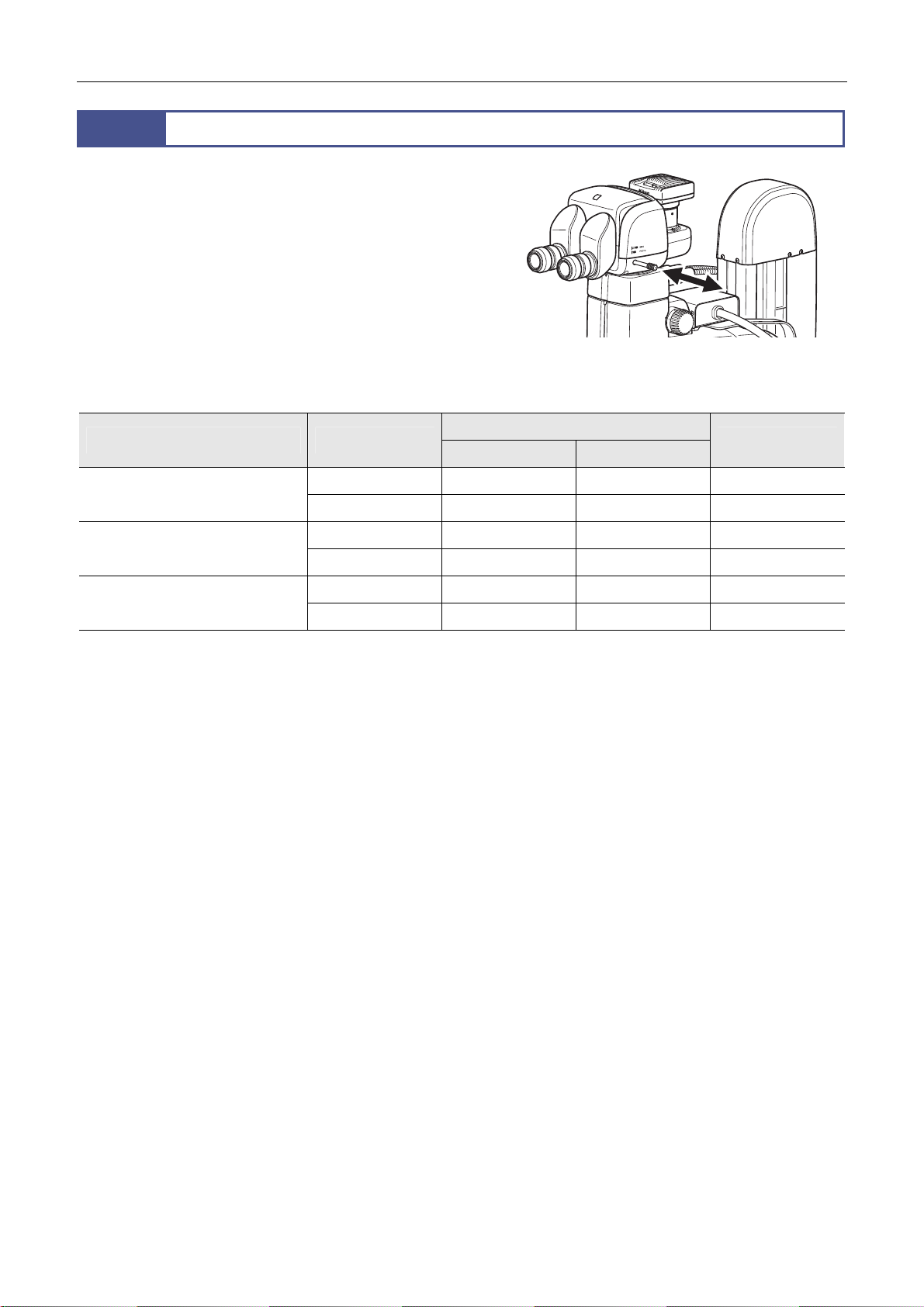
3
For observing a specimen using the eyepiece, switch the optical
path to the binocular part. For imaging using the DS camera head,
switch the optical path to the vertical tube. Use the optical path
switching lever of the tube to switch the optical path. Push or pull
the lever to make the desired selection. Be sure the lever is fully
pushed in or pulled out. Do not leave the lever stopped partway.
Switching the Optical Path of the Tube
Distribution of Light with Optical Path Switching (%)
Switching the optical path
Tube Lever position
P2-TERG 100 Trinocular Tilting
Tube
P2-TERG 50 Trinocular Tilting Tube Pulled out 100 100 0
P2-TL100 Trinocular Tube L Pulled out 100 100 0
* The light amount of the left eye is always 100%. The light from the optical path of the right eye is diverged to the vertical tube.
(Images of the right eye’s optical path are captured.)
Pulled out 100 100 0
Pushed in 100 0 100
Pushed in 100 50 50
Pushed in 100 0 100
Binocular part
Vertical tube*
Left Right
22
Page 37
Chapter 3 Specific Operations
1 2 3 4
DISPLAY
BRIGHTNESS
ESCAPE
ALZ
LIMIT
ZOOM
STEP
Z-RESET
Z-SPEED
ZOOM STEP
Coarse
FL Cube
ON/OFF
ON/OFF
ON/OFF
ON/OFF
Fine
Ex Fine1x1x
0.5x
0.1x
4
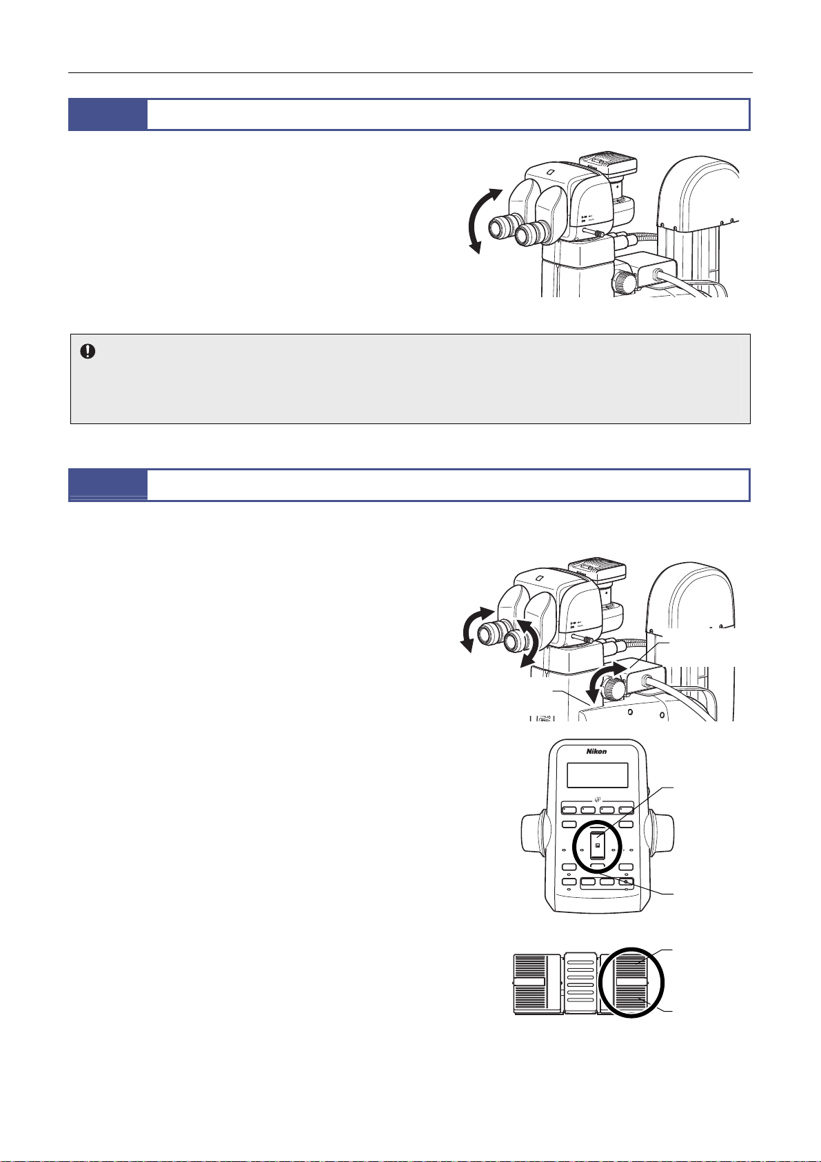
When the P2-TERG 100 Trinocular Tilting Tube or P2-TERG 50 is
used, the angle of the binocular part to facilitate microscopy can
be changed and adjusted.
The angle can be continuously changed by moving the binocular
part as indicated by the arrow in the figure.
The eye level can also be changed by turning the binocular part
180°.
(The low eye level P2-TL100 Trinocular Tube L does not have a
mechanism for adjusting the angle of depression.)
Notes on adjusting the angle of depression
Do not apply excessive force to the binocular part during depression angle adjustment. It may cause unexpected failure or
malfunction.
When moving the binocular part, be careful not to catch your fingers in the rotary section at the bottom of the binocular part.
Adjusting the Angle of Depression
Adjusting the angle of depression
5
Adjusting the Diopter
Adjust to match your diopter. This adjustment is required for each user.
1 Position the diopter adjustment rings of the right and left
eyepieces to 0.
2 Maximize the magnification, and then focus on the sample
using the focus knob.
(See “7 Focusing on the Sample.”)
3 Minimize the magnification, and then turn the diopter
adjustment rings of the right and left eyepieces to bring
them into focus separately.
[Image zooming]
SMZ18 Zooming Body: Zooming knob on the zooming body
SMZ25 Zooming Body: Zoom buttons on the remote
controller or the right pedal of the
foot switch
[Zoom magnification]
SMZ18 Zooming Body: 0.75x to 13.5x
SMZ25 Zooming Body: 0.63x to 15.75x
4 Repeat steps 2 and 3 to check the focus, so that changing
the magnification does not affect the focus and clear images
can be captured.
Magnification
decrease
FL Cube
DISPLAY
Z-SPEED
Coarse
Fine
ESCAPE
ON/OFF
ALZ
ON/OFF
+
Ex Fine
−
ZOOM
STEP
−+
ZOOM STEP
Z-RESET
0.5x
0.1x
LIMIT
ON/OFF
ON/OFF
Remote controller
Magnification
increase
BRIGHTNESS
Magnification
increase
Magnification
decrease
Magnification
increase
Magnification
Foot switch
decrease
Adjusting the diopter
23
Page 38
Chapter 3 Specific Operations
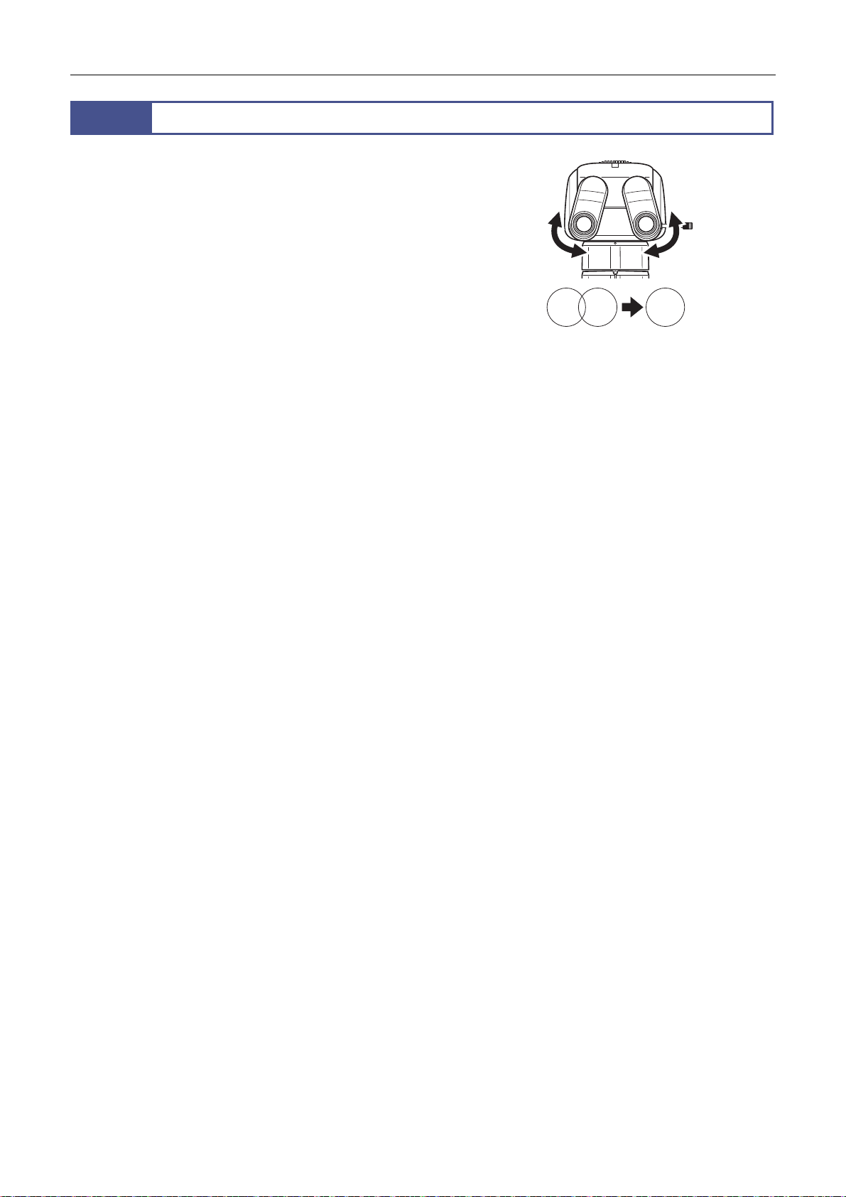
A
6
djust to match the distance between your right and left eyes.
This adjustment is required for each user.
Look into both eyepieces and move the binocular part of the tube
so that the right and left fields of view merge into a single circle.
Adjusting the Interpupillary Distance
Adjusting the interpupillary distance
24
Page 39
Chapter 3 Specific Operations
1 2 3 4
DISPLAY
BRIGHTNESS
ESCAPE
ALZ
LIMIT
ZOOM
STEP
Z-RESET
Z-SPEED
ZOOM STEP
Coarse
FL Cube
ON/OFF
ON/OFF
ON/OFF
ON/OFF
Fine
Ex Fine1x1x
0.5x
0.1x
7
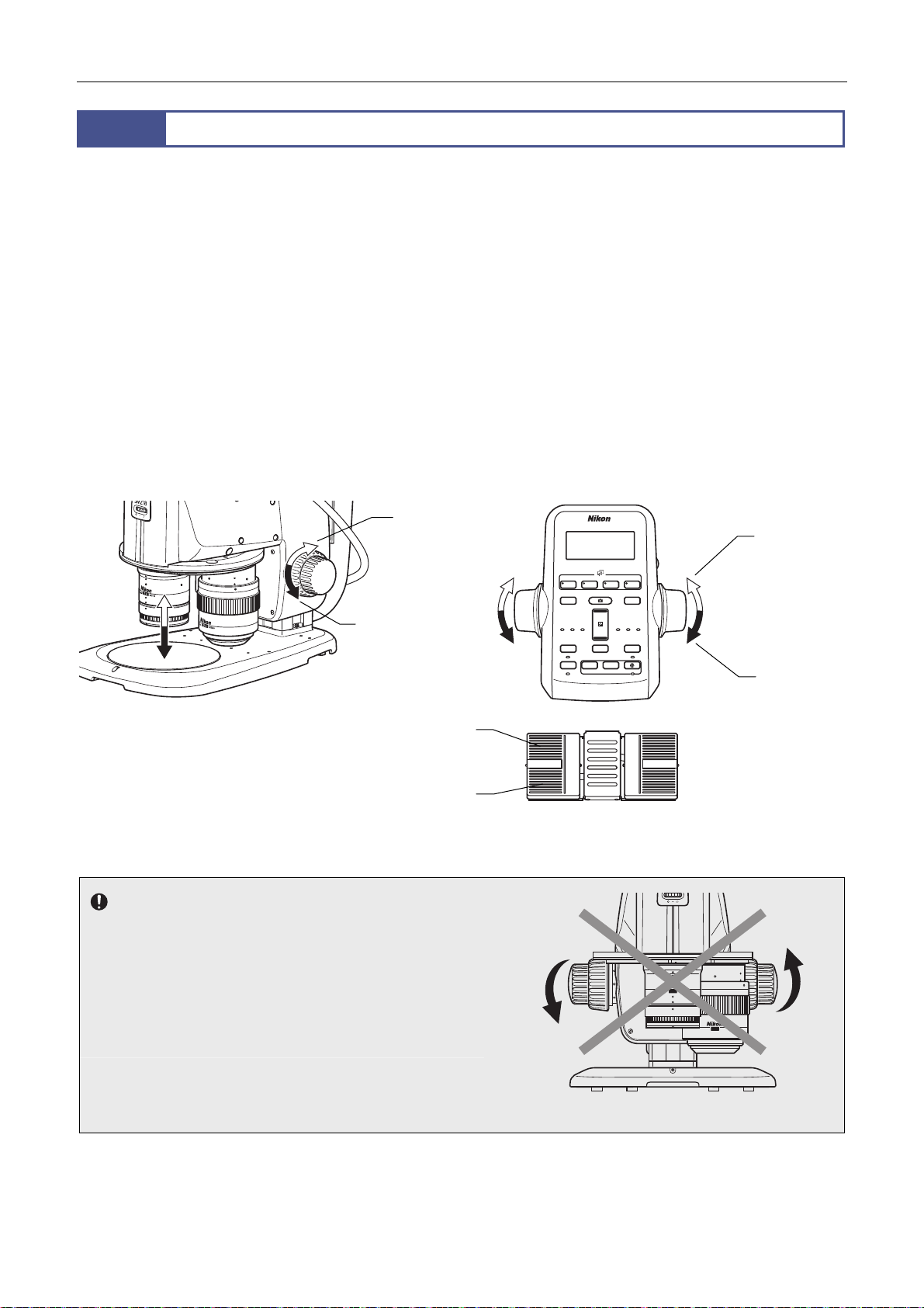
Focus adjustment of the sample is performed by the rotation of the focus knobs on the focus unit or focus mount. When the
remote controller or foot switch is connected, focusing can be adjusted using the focus knobs of the remote controller or the
foot pedals on the left side of the foot switch. To use the foot switch, the P2-RC Remote Controller or the P2-CTLA Control
Box must be connected.
[Focus operation]
Focus unit, focus mount, remote controller: Focus knob
The figure shows the turning directions of the focus knobs and the corresponding vertical movements of the focus mount.
Turning the knob backward: Upward movement
Turning the knob forward: Downward movement
Foot switch: Left foot pedal
Rear pedal: Upward movement
Front pedal: Downward movement
(See Chapter 4, “10.2 AZ-FSW Foot Switch.”)
Focusing on the Sample
Downward
movement
Left rear pedal
(Upward movement)
Upward
movement
Coarse
DISPLAY
ESCAPE
ON/OFF
ALZ
ON/OFF
Z-SPEED
Fine
FL Cube
+
Ex Fine
−
ZOOM
STEP
−+
ZOOM STEP
Z-RESET
0.5x
Upward
movement
BRIGHTNESS
0.1x
LIMIT
ON/OFF
ON/OFF
Downward
movement
Left front pedal
(Downward movement)
Notes on turning the focus knobs
When using the focus knobs of the focus unit, focus mount or
the remote controller, do not turn (or twist) the right and left
focus knobs in opposite directions at the same time. Doing so
may cause malfunction.
When the focus knobs of the focus unit or focus mount reach
their rotational limits for the unit’s vertical movement, do not
forcibly turn it further. Doing so may cause malfunction.
Focus operation
25
1 x
SHR Plan apo WD:60
2 x
SHR Plan apo WD:20
Do not turn the knobs in the opposite direction!
Page 40
Chapter 3 Specific Operations
1 Check that the optical path of the tube is 100% to the binocular part.
2 Using coarse control, lower the zooming body to a position near the working distance.
[Working distances of objectives]
0.5x: 71 mm
1x: 60 mm
1.6x: 30 mm
2x: 20 mm
3 Using fine control, precisely focus on the sample.
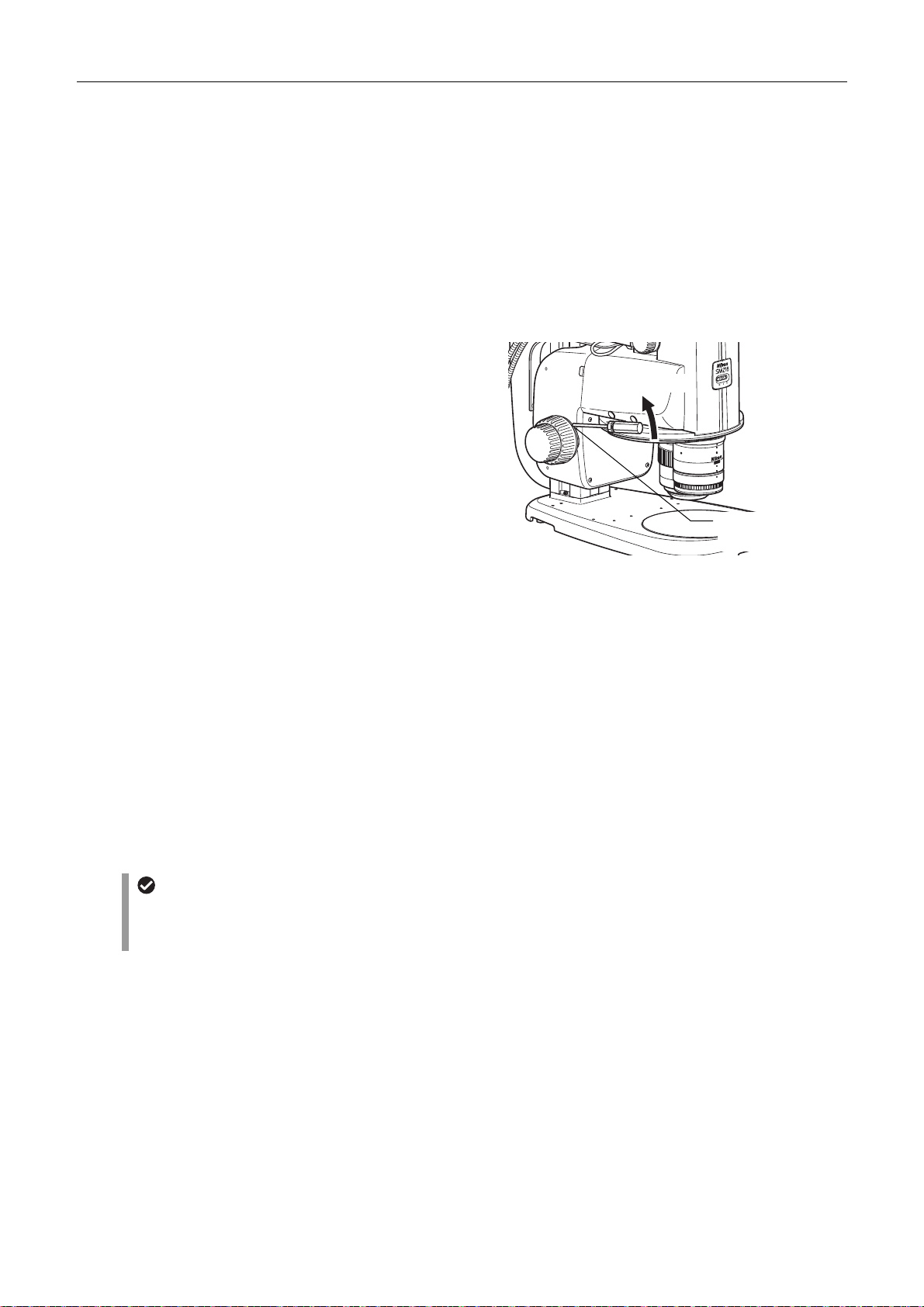
Torque of the focus knobs
For the P2-FU Focus Unit and P2-FMDN Focus Mount, the
torque of the coarse control knobs can be changed. To do this,
turn the torque adjustment ring on the base of the left coarse
focus knob using a hex driver (nominal designation, 2:
supplied with the focus unit). When the torque is too low, the
vertical position of the zooming body may slide due to various
loads (such as its own weight or the load of the
counterbalance spring inside the focus unit). Be sure to adjust
the torque to an appropriate level. Note that turning the fine
control knob will cause the coarse control knob to also turn,
changing the torque of the fine control knob.
Adjusting the torque of the focus knobs
Torque increase
2
WD:60
1x
Apo
n
a
l
P
SHR
Torque adjustment
ring
Focusing stroke
P2-FU Focus Unit
Focusing stroke: 100 mm
Stroke per rotation of the focus knobs Coarse control, 18.50 mm per rotation
Fine control, 3.27 mm per rotation
P2-MFU Motorized Focus Unit
Focusing stroke: 100 mm
P2-FMDN Focus Mount
Focusing stroke: 65 mm
Stroke per rotation of the focus knobs Coarse control, 18.50 mm per rotation
Fine control, 3.27 mm per rotation
Useful functions for focusing
When using the P2-MFU Motorized Focus Unit, the remote control enables the following remote operations: changing the
focus speed, setting the limit position, setting retracting, and resetting Z. For details, see Chapter 4, “2.2 P2-MFU
Motorized Focus Unit.”
* Also see Chapter 4, “2 Focus Units.”
26
Page 41
Chapter 3 Specific Operations
1 2 3 4
DISPLAY
BRIGHTNESS
ESCAPE
ALZ
LIMIT
ZOOM
STEP
Z-RESET
Z-SPEED
ZOOM STEP
Coarse
FL Cube
ON/OFF
ON/OFF
ON/OFF
ON/OFF
Fine
Ex Fine1x1x
0.5x
0.1x
8
Besides changing the magnification with the zooming body, this microscope system enables the magnification to be changed
by switching the objectives when used with the P2-RNI2 Intelligent Nosepiece and equipped with two objectives having
different magnification ratios.
8.1
The magnification of the zooming body can be changed by zooming in and out.
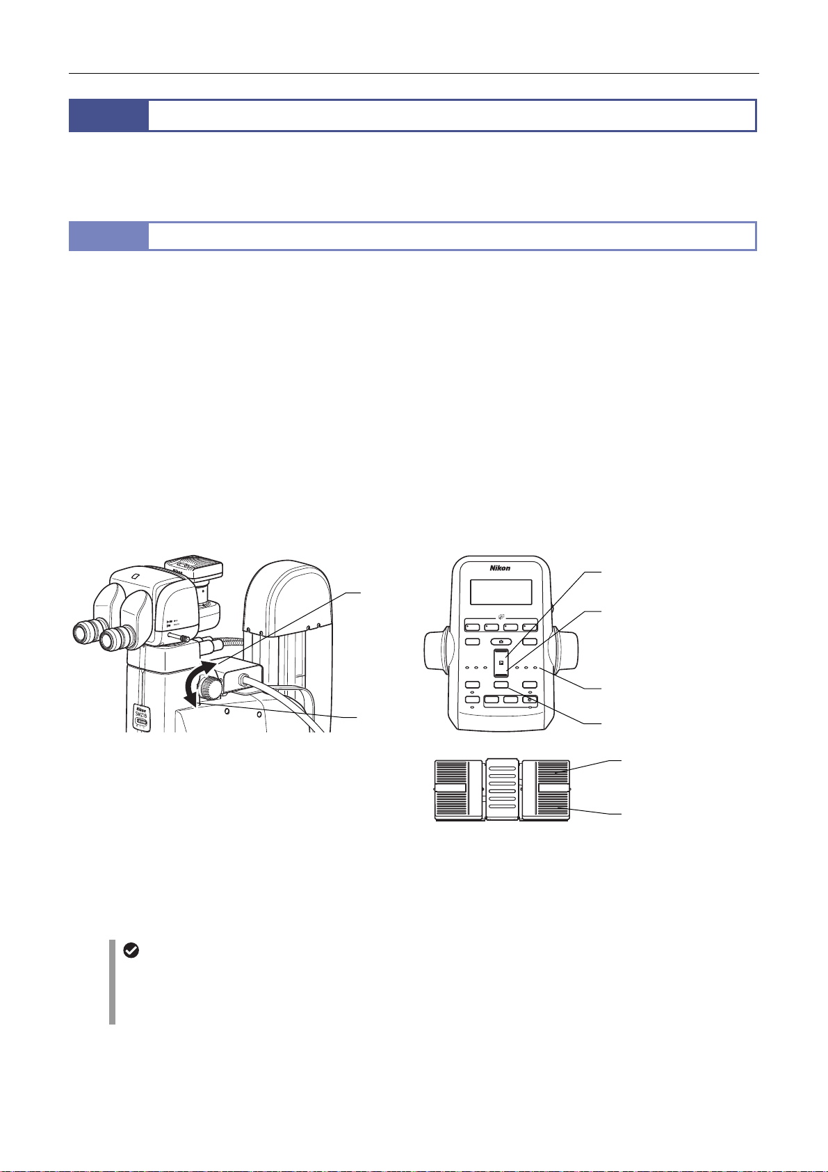
[Image zooming]
SMZ18: Zooming knobs of the Zooming Body
SMZ25: Zoom buttons of the remote controller
Changing the Magnification
Image Zooming
The figure shows the turning directions of a knob and the corresponding changes in the magnification.
Turning the knob backward: Magnification increase
Turning the knob forward: Magnification decrease
Upper button: Magnification increase
Lower button: Magnification decrease
Pressing and holding the buttons causes the magnification to change continuously.
Right foot pedal of the foot switch
Rear-side pedal: Magnification increase
Front-side pedal: Magnification decrease
(See Chapter 4, “10.2 AZ-FSW Foot Switch.”)
■ Magnification and zoom ratio
SMZ18: 0.75 to 13.5x, 18:1
SMZ25: 0.63 to 15.75x, 25:1
Useful functions for image zooming
When using the SMZ25 Zooming Body, the magnification step size can be switched by pressing the zoom step switching
button of the remote controller. The magnification can also be switched automatically so that the field of view before
switching is maintained when the objective is switched (ALZ function). For details, see Chapter 4, “1.2 SMZ25 Zooming
Body.”
Magnification
increase
Magnification
decrease
Image Zooming
27
Coarse
DISPLAY
Z-SPEED
ESCAPE
ON/OFF
ALZ
ON/OFF
Fine
Ex Fine
FL Cube
+
−
ZOOM
STEP
−+
ZOOM STEP
0.5x
Z-RESET
Upper zoom button
(magnification increase)
BRIGHTNESS
Lower zoom button
(magnification decrease)
0.1x
LIMIT
ON/OFF
ON/OFF
Zoom step indicator
Zoom step switching
button
Right rear pedal
(Magnification increase)
Right front pedal
(Magnification decrease)
Page 42
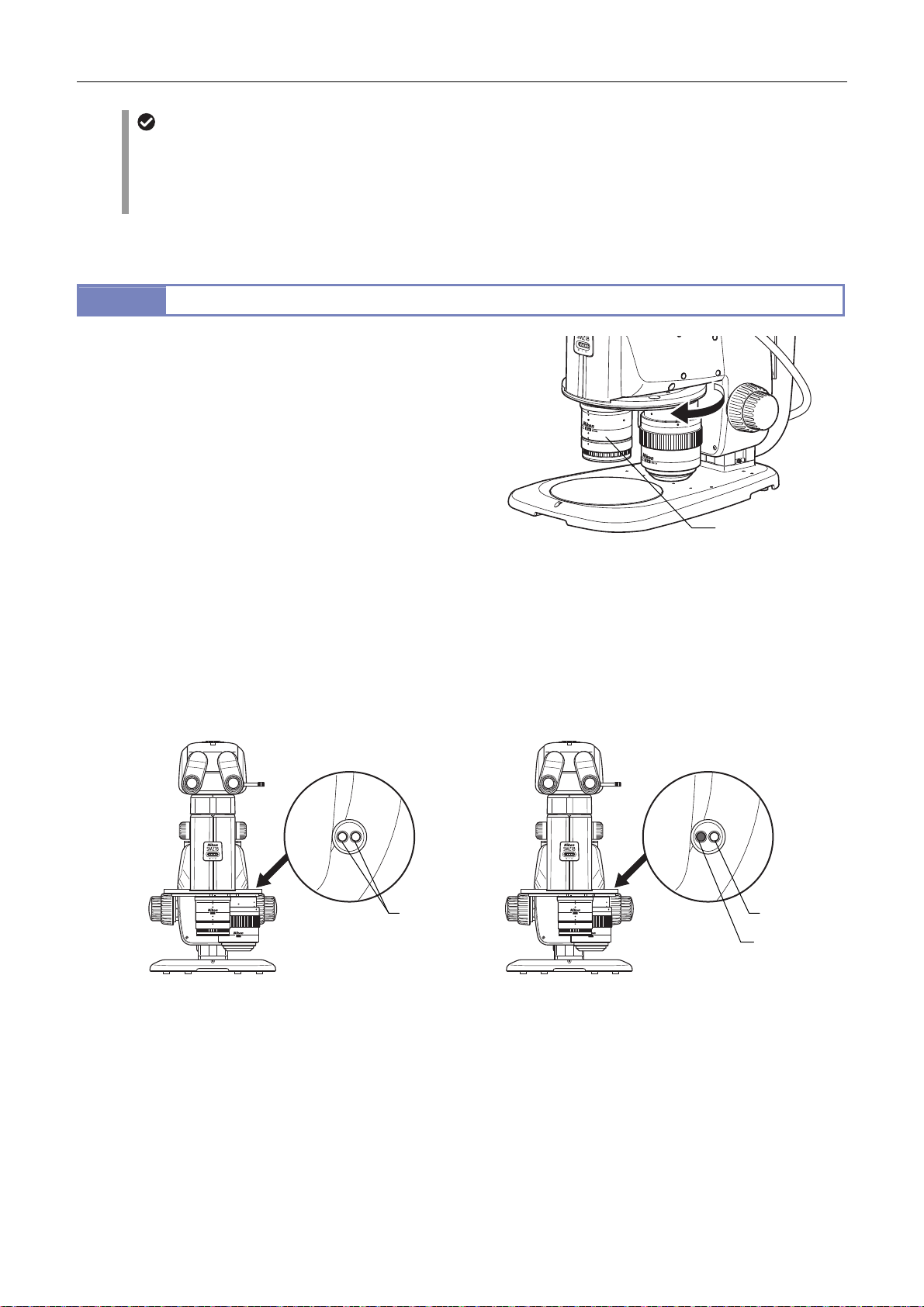
Chapter 3 Specific Operations
p
Total magnification
The total magnification of the microscope is determined from the formula below:
Total magnification = zoom magnification x object’s magnification x eyepiece’s magnification
When using a vertical tube, replace the eyepiece’s magnification with the C mount adapter lens’ magnification to
calculate the total magnification.
* Also see Chapter 4, “1 Zooming Body.”
8.2
Switching Objectives (Using the P2-RNI2 Intelligent Nosepiece)
The P2-RNI2 Intelligent Nosepiece can be attached with two of
the following objectives: P2-SHR Plan Apo 0.5X, 1X, 1.6X and
2X. The attached objectives can be switched by turning the
nosepiece. Check that the objective falls into the click position
when turning the nosepiece.
Stereoscopic view and vertical view
An intelligent nosepiece has two click positions for each
objective.
The click position switches between stereoscopic view and
vertical view. Microscopy with vertical view is possible when
needed, for example when taking a picture.
The click position of the objective can be checked by the
position of the objective viewed from the front or the color of
the hole on the objective status display area on the intelligent
nosepiece.
* Also see Chapter 4, “3.1 P2-RNI2 Intelligent Nosepiece.”
Objective state
indication
Objective on the
tical path
o
Switching Objectives
Objective state
indication
SHR Plan apo WD:60
1 x
2 x
SHR Plan apo WD:20
White White
SHR Plan apo WD:60
1 x
SHR Plan apo WD:20
2 x
Black
Stereoscopic view Vertical view
Objective position state (stereoscopic view and vertical view)
28
Page 43
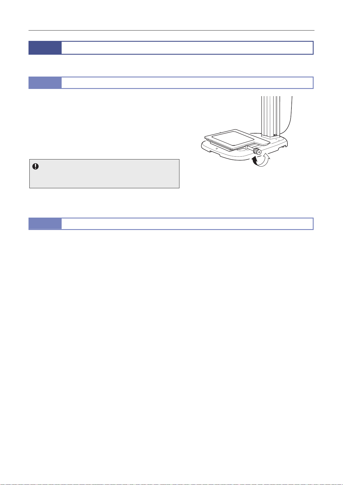
Chapter 3 Specific Operations
9
To view another part of a sample during microscopy, use the following procedure to shift the sample.
9.1
Turn the XY shift knob of the P-SXY64 XY Stage mounted instead
of the stage plate to shift the sample on the glass plate and
change the part to be observed.
XY stroke of the stage with the X/Y shift knob and stroke
per rotation of the knob
X: 150 mm; 37.5 mm per rotation
Y: 100 mm; 24.1 mm per rotation
Usage restriction
If the P-SXY64 XY Stage is mounted on the P-PS32 Plain Stand,
the movement of the stroke in the Y direction is restricted.
* Also see Chapter 4, “5.5 P-SXY64 XY Stage.”
9.2
Remove the stage plate from the base and attach the C-SSL DIA Sliding Stage or C-TRS Tilting Stage in place so that the
sample can be tilted or moved slightly.
Shifting a Sample
Shifting the Stage in the X and Y Directions (P-SXY64 XY Stage)
Shift using the P-SXY64 XY Stage
Using the Sliding Stage
29
Page 44
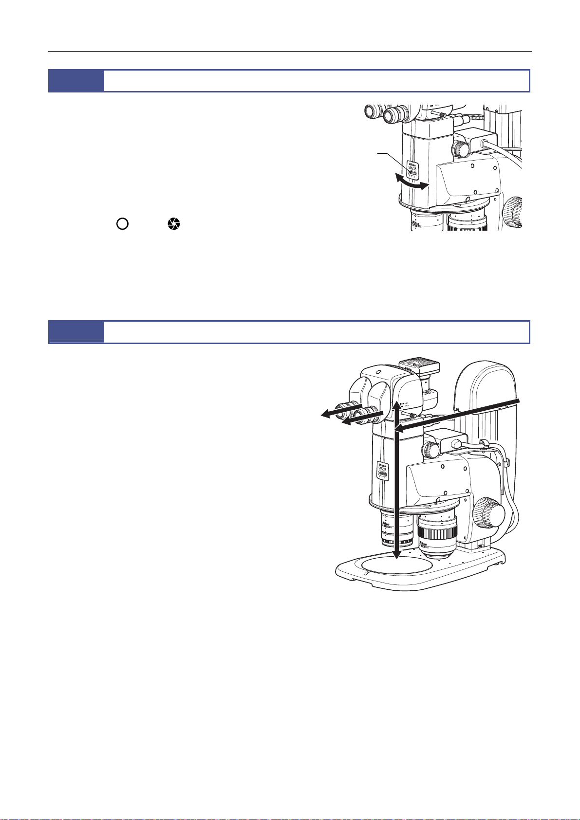
Chapter 3 Specific Operations
r
A
p
10
The SMZ18 and SMZ25 Zooming Bodies contain an aperture
diaphragm.
Turn the aperture diaphragm dial to adjust the aperture.
The aperture can be adjusted in the range from fully open to 3
mm dia.
Opening and closing the aperture diaphragm causes the
brightness and focus depth to change resulting in a change in
resolution.
Open Close
Brightness Bright Dark
Focus depth Shallow Deep
Resolution High Low
Using the Aperture Diaphragm
perture
dia
hragm dial
Adjusting the aperture diaphragm
11
The microscope system enables episcopic illumination when
used with the devices listed below. All of the devices use LEDs as
the light source and provide uniform illumination.
Illumination led from the light source by the fiber is emitted to a
sample through an objective or directly so that an image resulting
from the light reflected from the sample is observed. Episcopic
illumination is used for observing samples which do not transmit
light such as metal and mineral sections.
In addition, if the P2-CI Coaxial Epi Illuminator is attached,
illumination along the optical axis for observation can also be
emitted, which is effective for observing samples such as metallic
mirrors, resins having smooth surfaces, and semiconductor
s.
wafe
See Chapter 4, “7 Episcopic Illuminator” and select the
appropriate device based on the objective of microscopy.
P2-CI Coaxial Epi Illuminator
C-FDF Flexible Double Arm Fiber Illumination Unit
P2-FIR Ring Fiber Illumination Unit
P2-FIRL LED Ring Illumination Unit
For the operations of the light sources such as brightness
adjustment, refer to the instruction manuals of the light sources.
Using Episcopic Illumination
Episcopic illumination with
the P2-CI Coaxial Epi Illuminator
30
Page 45
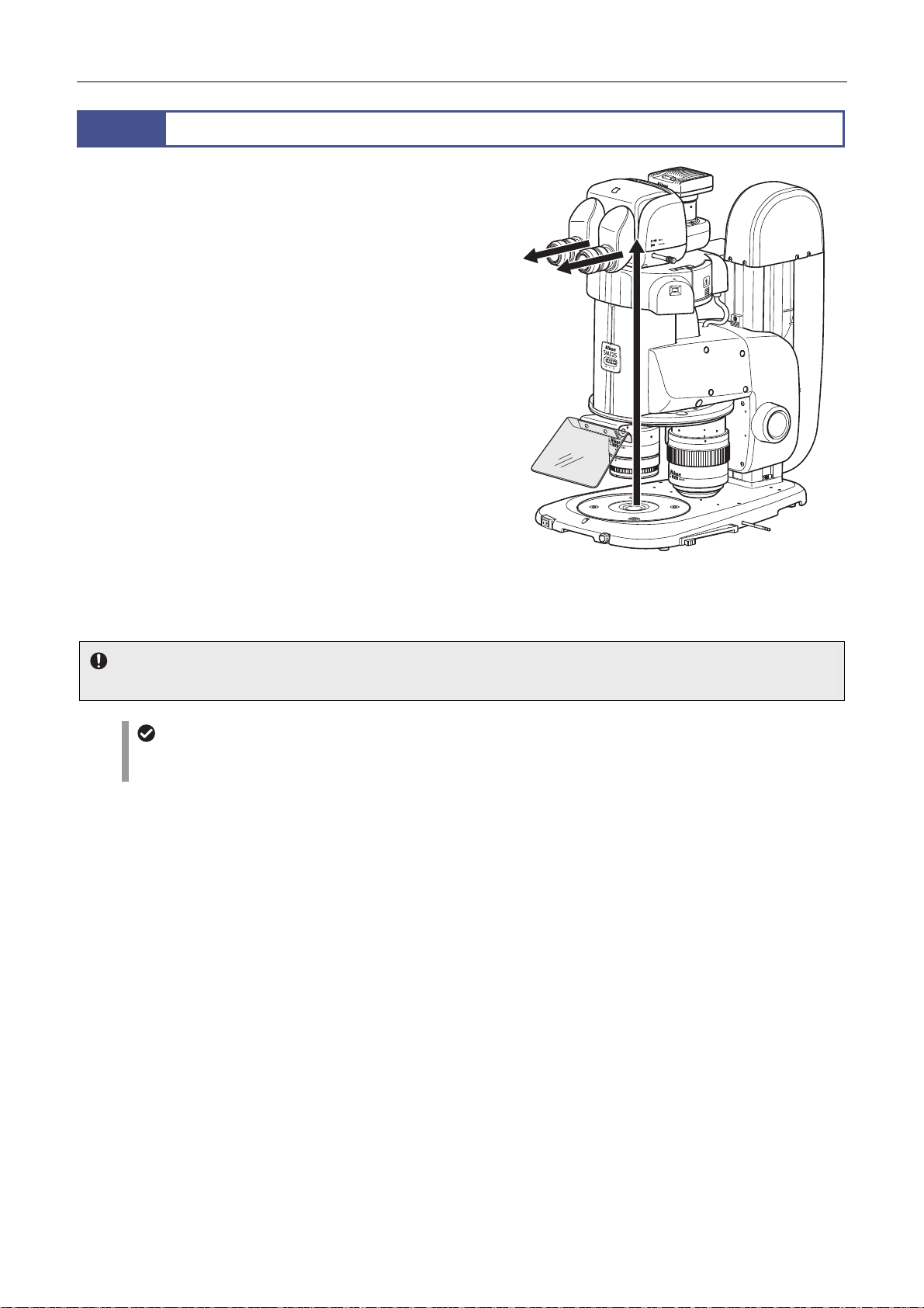
Chapter 3 Specific Operations
12
The microscope system enables diascopic illumination when
used with the devices listed below. All of the devices use LEDs as
the light source and provide uniform illumination.
The image to be observed results from diascopic illumination
which passes through the sample and enters the objective.
Diascopic illumination is used for observing transparent
substances such as macromolecular compounds, fibers, and
glass and tissue sections and biological specimens in petri
dishes.
In addition, optional devices can be attached to enable dark-field
diascopic illumination and diascopic simplified/polarized
illumination. This allows for the observation of samples that are
difficult to be observed under ordinary bright-field diascopic
illumination such as transparent materials and crystals and
tissues and minute organisms in culture solutions.
See Chapter 4 “8 Diascopic Illuminator” and select the
appropriate device based on the objective of microscopy.
P2-DBL LED Diascopic Illumination Base
P2-DBF Fiber Diascopic Illumination Base
P-DF LED Dark Field Unit
P2-POL Simple Polarizing Attachment
Using Diascopic Illumination
Diascopic illumination with the P2-DBL LED
Diascopic Illumination Base
Empty cube
When an epi-fluorescence attachment is mounted, check that the empty cube of the attachment is in the optical path.
OCC illumination
The P2-DBL LED Diascopic Illumination Base and P2-DBF Fiber Diascopic Illumination Base support OCC illumination
(oblique illumination). OCC illumination, which offers high contrast, is appropriate for microscopy of phase objects.
31
Page 46
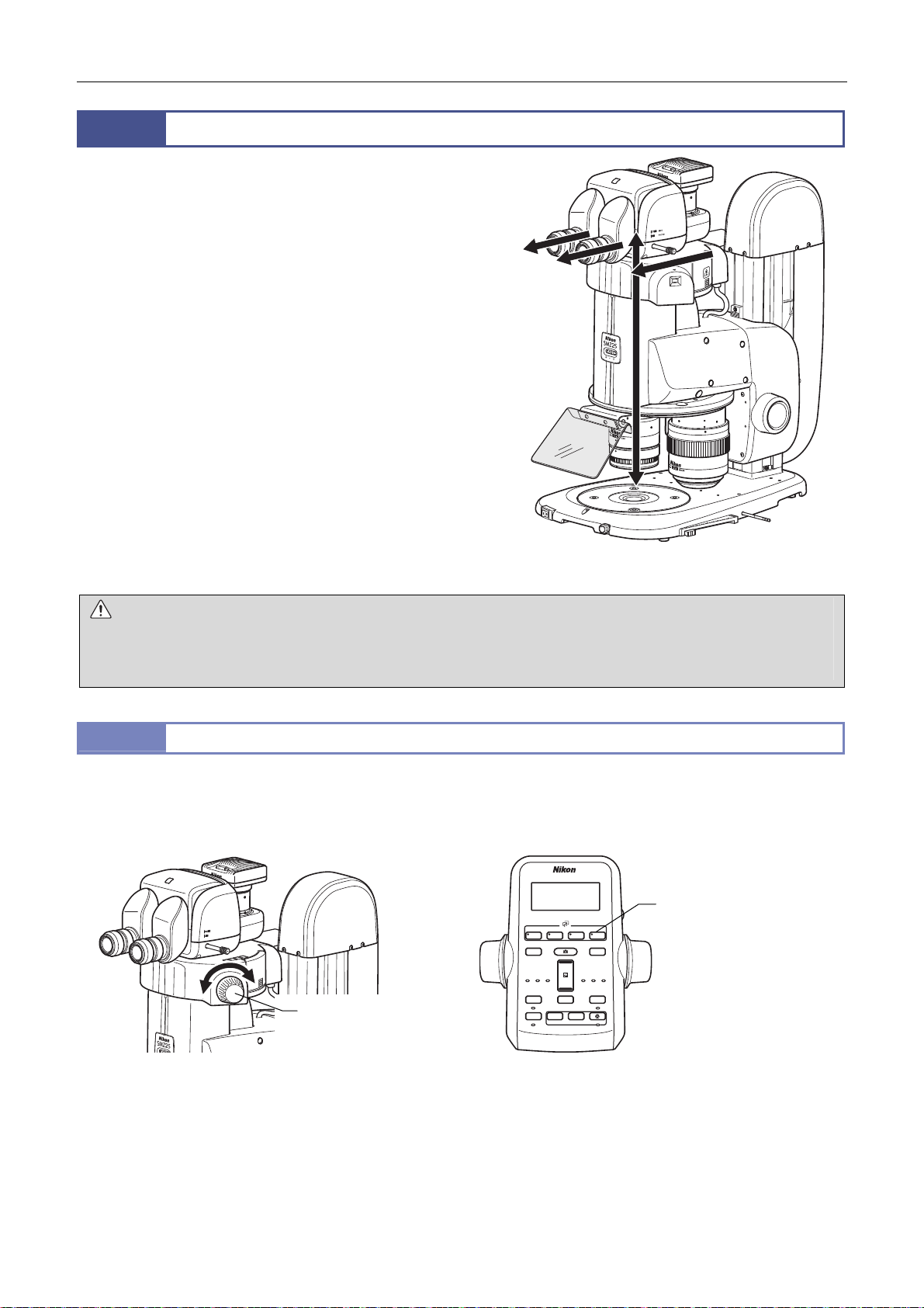
Chapter 3 Specific Operations
1 2 3 4
DISPLAYDISPLAY
BRIGHTNESSBRIGHTNESS
ESCAPEESCAPE
ALZALZ
−+
LIMITLIMIT
ZOOMZOOM
STEPSTEP
Z-RESETZ-RESET
Z-SPEEDZ-SPEED ZOOM STEPZOOM STEP
CoarseCoarse
FL CubeFL Cube
ON/OFFON/OFF ON/OFFON/OFF
ON/OFFON/OFF ON/OFFON/OFF
FineFine Ex FineEx Fine 1x1x 0.5x0.5x 0.1x0.1x
+
−
13
Epi-fluorescence microscopy used for observing fluorescence
images requires an optical element such as a fluorescence filter,
and a brighter light source including mercury lamp.
In this microscope system, state detection or motorized-type
epi-fluorescence illumination is available. With a filter cube
attached to the device, the filter cube is brought into the optical
path by the rotation of the turret, resulting in the generation of
epi-fluorescence illumination. The light source is a precentered
high-intensity mercury lamp.
Illumination led from the light source to the device by the HG fiber
passes through a fluorescence filter and emits excitation light to
the sample so that fluorescent images can be observed.
See Chapter 4, “9 Epi-Fluorescence Attachment” and select the
appropriate device based on the objective of microscopy.
P2-EFLI Epi Fluorescence Attachment
P2-EFLM Motorized Epi Fluorescence Attachment
For details on adjusting the light sources such as brightness
adjustment, refer to the instruction manuals of the light sources.
WARNING
The light source used with the epi fluorescence attachment (mercury lamp) requires special care during handling because of its
characteristics. Make sure you are familiar with and observe all warnings and cautions described at the beginning of this
instruction manual.
13.1
The turret of the epi fluorescence attachment is rotated to switch the four filter cubes attached to the turret.
Using Epi-Fluorescence Illumination
Switching Filter Cubes
Epi-fluorescence illumination with the epi
fluorescence attachment
[Turret rotation operation]
P2-EFLI Epi Fluorescence Attachment: Filter cube switching knob of the device
P2-EFLM Motorized Epi Fluorescence Attachment: Filter cube switching buttons of the remote controller
Filter cube switching
BINO
PHOTO
1
2
buttons
Filter cube switching
knob
Switching filter cubes
On the P2-EFLI Epi Fluorescence Attachment, turn the filter cube switching knob to assign to the indicator the turret address
(FL1 to FL4) of the filter cube to be placed into the optical path.
On the remote control, press the filter cube switching buttons (FL1 to FL4) to specify the turret address of the filter cube to be
placed into the optical path. The LED of the pressed button lights so that the turret address on the optical path can be
identified. The motorized epi fluorescence attachment has a turret address view window on the right front so that the turret
address on the optical path can be identified.
32
Page 47
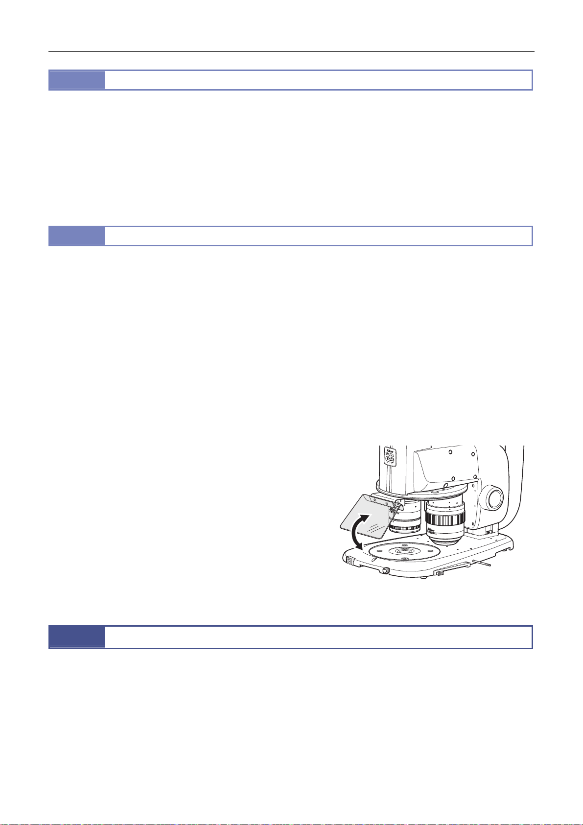
Chapter 3 Specific Operations
13.2
The epi fluorescence attachment can be equipped with the following filter cubes:
P2-EFL GFP-B, P2-EFL GFP-L, and P2-EFL RFP Filter Cube: Used for fluorescence observation with a given wavelength.
P2-EFLC Filter Cube: Used for fluorescence observation with an arbitrary wavelength when combined with arbitrary filters,
for example.
P2-EFLBF Filter Cube (Bright Field): Used for bright-field episcopic observation.
Empty cubes (three cubes supplied with an epi-fluorescence attachment): Used when performing diascopic illumination
observation using the epi-fluorescence attachment.
13.3
Using non-fluorescent slide glass and cover glass
When performing fluorescence observation of samples with a slide glass or cover glass, be sure to use non-fluorescent
slide glass or cover glass to obtain a high-contrast image.
Locating a target in the sample
For epi-fluorescence microscopy, Nikon recommend locating a target with bright-field diascopic illumination (OCC
illumination) and then switching to epi-fluorescence rather than emitting strong excitation light to the sample from the
beginning. When doing so, follow the operational tips below:
Start with low magnification under bright-field diascopic illumination.
If the sample is not transparent, use the P2-EFLBF Filter Cube (Bright Field) to obtain the entire image by reflected light.
Gradually increase the magnification. When the target becomes difficult to locate, switch to epi-fluorescence and use
low excitation light.
Selecting a Filter Cube
Important Notes for Epi-Fluorescence Microscopy
Protection from ultraviolet light (light shielding plate)
The light shielding plate is used to prevent the reflected
ultraviolet light, which is originally emitted through the
objective, from entering the observer’s eyes from the sample.
Using the light shielding plate
14
The microscope system enables remote control of several functions including focusing and changing magnification. The
following remote control devices can be used when connected with the P2-CTLA Control Box:
P2-RC Remote Controller
AZ-FSW Foot Switch
AZ-PCR Photo Release
For details, see Chapter 4 “10 Remote Control Device.”
Remote control from NIS-Elements is also possible by connecting the USB connector on the control box to a personal
computer. For details, refer to the NIS-Elements instruction manual.
Remote Operation
33
Page 48
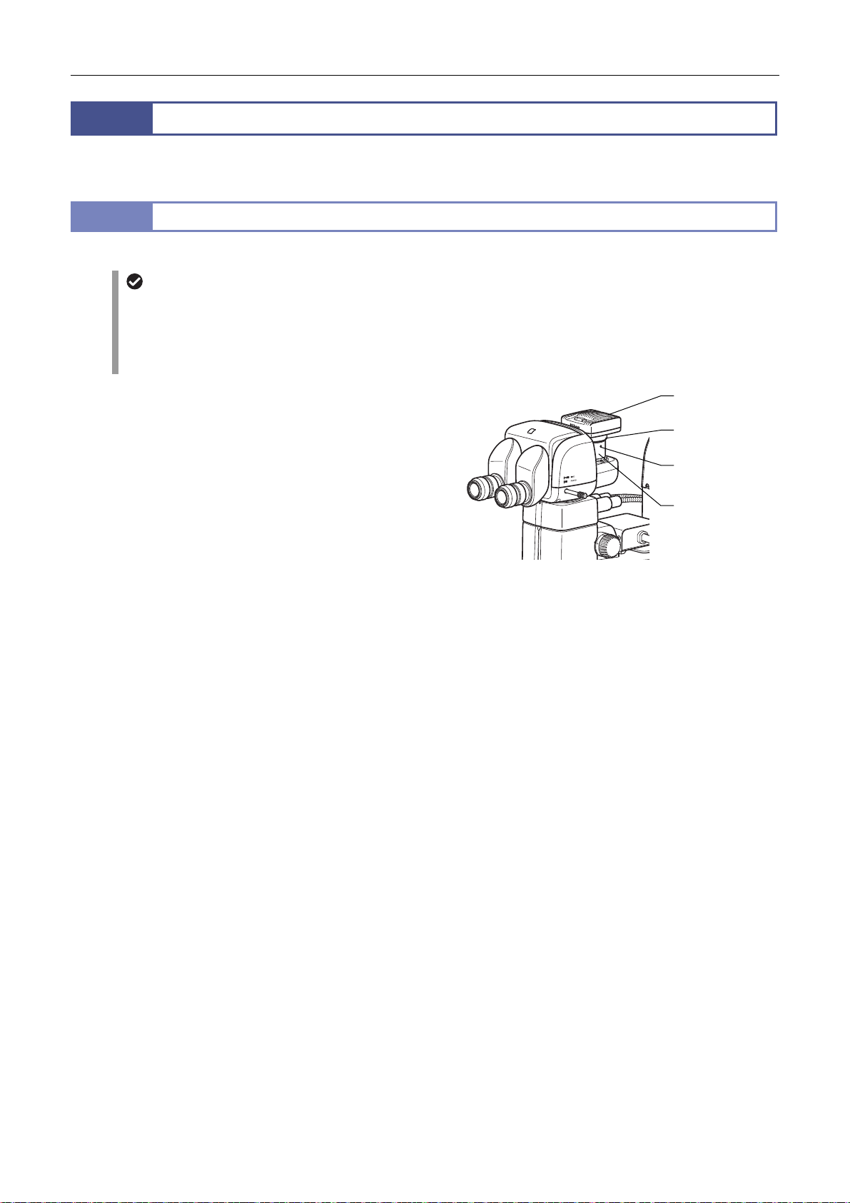
Chapter 3 Specific Operations
A
A
15
The microscope system can capture images of the sample being observed by attaching a camera such as a DS camera
head to the vertical tube via a TV tube adapter or C-mount adapter.
15.1
Follow the procedure below to capture images. For the camera settings, see the instruction manual for the DS-L3 or DS-U3.
(1) Adjust the illumination of the microscope correctly and
the focus of the sample image.
(2) Adjust the mounting orientation of the DS camera head.
For details about attaching the camera head, see [5] Attach
a Camera in Chapter 5, “3.3 Assembly of Other Devices
(Optional).”
Since shifting a sample horizontally causes the image on
the monitor to move horizontally, loosen the attachment
guide fixing screw and adjust the orientation of the camera.
After making the appropriate adjustments, tighten the screw.
Capturing Images
Procedure for Capturing Images
Using the DS-L3
Specify the following items beforehand.
Folder to save
Name of the save file (or select Auto.)
File format and file size of the save file
Date and destination of the data
DS camera head
C-mount adapter
ttachment guide
fixing screw
LV-TV TV Tu be
dapter
Adjusting the camera orientation
(3) Select the camera scene mode suitable for the microscopy type.
(4) Adjust the camera’s white balance.
When using diascopic illumination, first capture an image of the top surface of the stage glass. When using episcopic
illumination, first capture an image of any white subject. Then, press the WB button to execute white balance
adjustment. (For fluorescent photomicrography, Nikon recommends adjusting the white balance under normal
bright-field microscopy conditions before capturing images.)
(5) Adjust the position of the sample.
(6) Readjust the focus on the target.
(7) Adjust the image brightness using the camera exposure compensation function.
(8) Press the Pause button on the DS-L3 to check the image.
(9) Save the image if acceptable.
To save the image, press the capture button on the remote controller or DS-L3, or step on the pedal of the AZ-PCR
Photo Release.
34
Page 49

Chapter 3 Specific Operations
15.2
Confirming the photomicrographic range
The image on the monitor represents the photomicrographic range.
Adjusting to eliminate extraneous light
Cover the eyepiece with a piece of cloth or similar item.
Protecting fluorescent images from decoloration
The fluorescence of specimens may fade during exposure. To prevent this, do the following:
Adjusting the excitation light
Excessively bright excitation light will accelerate the decoloration of the sample making it more difficult to obtain
suitable fluorescent images. Use the ND filter of the light source to perform adjustment.
Sample
Photomicrography of the color-fading portion requires a prolonged exposure time resulting in poor color reproduction
and low-quality images. Move the sample so that the image of the portion that has not been exposed to excitation light
can be captured. To obtain the best results, use the diascopic illumination method to select a specimen section for
photomicrography, and then switch to the fluorescent method to capture the image.
Tips on Microscope Settings for Photomicroscopy
Using the shutter
When not performing observation, close the shutter.
Adjusting the brightness of the image on the monitor
When observing images on the monitor via a camera, the brightness can be changed also by making an adjustment on
the camera side, for example, by changing the display mode, exposure mode and photometry mode, by compensating
the exposure or by adjusting the image level.
For details, refer to the instruction manual for the DS-L3 or DS-U3.
35
Page 50
Chapter 3 Specific Operations
16
In stereo microscopes, the following information saved in the control box is read and used. The lower limit and the escape
distance are previously set when the product is shipped. Other items are set to OFF or nothing is set. When using a
motorized system or intelligent (status detection) system for the first time, set the items as required by following the specified
procedures. For details, see the instruction manual supplied with the corresponding product.
Objective - NIS-Elements and setup tools, DS-L3
Eyepiece - Setup tools, DS-L3
Epi-fl filter cube - NIS-Elements and setup tools, DS-L3
Motorized focus unit lower limit 0 mm NIS-Elements, remote controller *
Motorized focus unit escape distance 20 mm NIS-Elements and setup tools
ALZ function OFF NIS-Elements and setup tools, remote controller *
Internally Saved Information
P2-CTLA Control Box
Items Default Tools
P2-CTLB Control Box
Items Default Tools
Objective - NIS-Elements and setup tools, DS-L3
Eyepiece - Setup tools, DS-L3
Epi-fl filter cube - NIS-Elements and setup tools, DS-L3
*: The setting can be changed but cannot be saved.
36
Page 51

Chapter
4
Functions and Operations of
the Devices
This chapter describes the main functions and how to use the devices.
37
Page 52
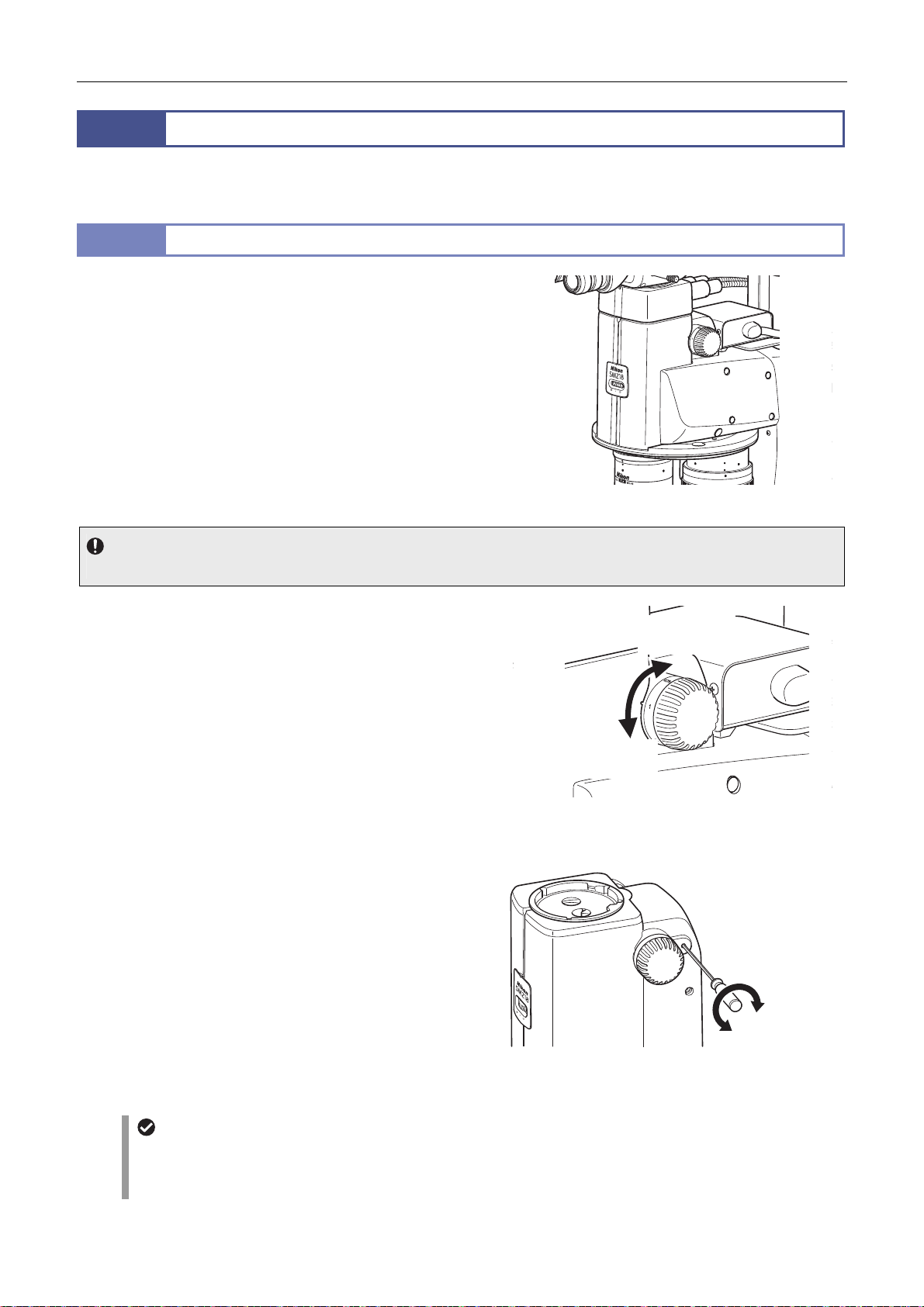
Chapter 4 Functions and Operations of the Devices
A
f
1
Two types of zooming bodies are available: SMZ18 Zooming Body for manual zoom operations and SMZ25 Zooming Body
for motorized zoom drive.
1.1
This model, which offers high NA, is designed for manual zoom
operations.
For systems where a control box has been connected, the zoom
information is sent to the control box via a motorized focus unit or
relay box, and then transmitted to the DS-L3 DS Camera Control
Unit and personal computer.
For the objective, the SHR-Plan Apo 0.5x, 1x, 1.6x, or 2x can be
attached. When combined with the P2-RNI2 Intelligent
Nosepiece, two objectives can be attached.
focus unit can be connected through the P2-RNI2 Intelligent
Nosepiece or the P2-FM Focus Mount Adapter.
The P2-FMDN Focus Mount can also be attached.
Zooming Body
SMZ18 Zooming Body
SMZ18 Zooming Body
Usage restriction
Tubes, intermediate tubes and objectives of the previous SMZ series cannot be used.
Images can be zoomed in and out using the zooming knobs on
the right and left sides of the zooming body.
Turning the knob backward: Magnification increase
Turning the knob forward: Magnification decrease
Turning the knob causes the magnification to continuously
change in the range from 0.75x to 13.5x (18:1 zoom ratio).
Magnification values are marked on the zooming knobs.
Click stop of the zooming knobs operates at the positions of
0.75x, 1x, 2x, 3x, 4x, 5x, 6x, 8x, 10x, 12x, and 13.5x. It is also
possible to deactivate the click stop function.
Activating and deactivating click stop of zoom operations
Insert the hex driver (nominal designation: 2) supplied with the
focus unit into the hole on the rear side of the right zooming knob.
Turn the internal screw counterclockwise to activate click stop.
Turn it clockwise to deactivate click stop.
Magnification
decrease
Zoom operation
Magnification
increase
0.75
1
2
Deactivating
click stop
Activating
click stop
Activating and deactivating click stop
o
Aperture diaphragm
The zooming body is equipped with an aperture diaphragm dial which enables the diaphragm of the right and left optical
paths to be simultaneously adjusted in the range from fully open to 3 mm dia.
For details about using the aperture diaphragm, see Chapter 3, “10 Using the Aperture Diaphragm.”
zoom operations
38
Page 53
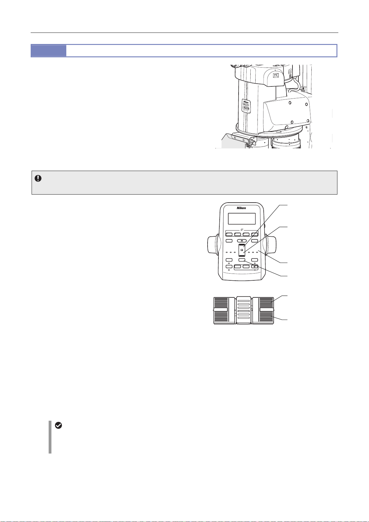
Chapter 4 Functions and Operations of the Devices
A
1 2 3 4
DISPLAY
BRIGHTNESS
ESCAPE
ALZ
LIMIT
ZOOM
STEP
Z-RESET
Z-SPEED
ZOOM STEP
Coarse
FL Cube
ON/OFF
ON/OFF
ON/OFF
ON/OFF
Fine
Ex Fine1x1x
0.5x
0.1x
1.2
This model, which offers high NA, is designed for motorized zoom
operations.
Zoom control is performed by the P2-CTLA Control Box. Control
signals are sent to the SMZ25 via a motorized focus unit or relay
box. The zoom information is sent to the control box via a
motorized focus unit or relay box, and then transmitted to the
DS-L3 DS Camera Control Unit and personal computer.
For the objective, the P2-SHR Plan Apo 0.5X, 1X, 1.6X or 2X can
be attached. When combined with the P2-RNI2 Intelligent
Nosepiece, two objectives can be attached.
focus unit can be connected through the P2-RNI2 Intelligent
Nosepiece or the P2-FM Focus Mount Adapter.
Usage restriction
Tubes, intermediate tubes and objectives of the previous SMZ series cannot be used
Images can be zoomed in and out using the zoom buttons on the
remote controller.
Upper zoom button: Magnification increase
Lower zoom button: Magnification decrease
Each time the button is pressed, the magnification changes in the
range from 0.63x to 15.75x (25:1 zoom ratio) in steps. The step
size depends on the setting of the zoom step switching button.
Pressing and holding the button causes the magnification to
change continuously.
Magnification step size
Each time the zoom step switching button on the remote
controller is pressed, the step size changes in the following
order: 1x, 0.5x then 0.1x.
When a step size is selected, the corresponding step LED
indicator lights.
The right pedals of the foot switch can also be used to zoom in
and out images as well as the zoom buttons on the remote
controller.
Right rear pedal: Magnification increase
Right front pedal: Magnification decrease
Each time the pedal is pressed, the magnification changes by one
step. The step size depends on the setting of the zoom step
switching button on the remote controller. Pushing and holding
the pedal causes the magnification to change continuously.
SMZ25 Zooming Body
SMZ25 Zooming Body
Upper zoom button
(magnification
increase)
Lower zoom button
(magnification
decrease)
Zoom step indicator
Zoom step
switching button
Coarse
DISPLAY
Z-SPEED
ESCAPE
ON/OFF
ALZ
ON/OFF
Fine
Ex Fine
FL Cube
+
−
ZOOM
STEP
−+
Z-RESET
ZOOM STEP
0.5x
BRIGHTNESS
0.1x
LIMIT
ON/OFF
ON/OFF
Right rear pedal
(magnification
increase)
Right front pedal
(magnification
decrease)
Zoom operation
Aperture diaphragm
The zooming body is equipped with an aperture diaphragm dial which enables the diaphragm of the right and left optical
paths to be simultaneously adjusted in the range from fully open to 3 mm dia.
For details about using the aperture diaphragm, see Chapter 3, “10 Using the Aperture Diaphragm.”
39
Page 54
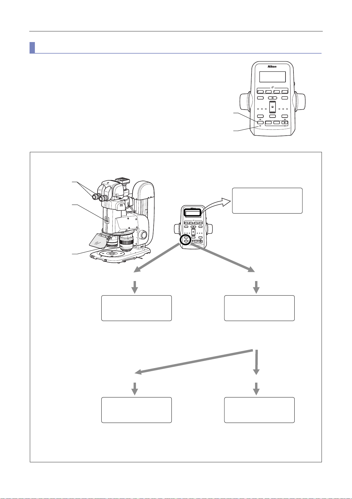
Chapter 4 Functions and Operations of the Devices
A
1 2 3 4
DISPLAY
BRIGHTNESS
ESCAPE
ALZ
LIMIT
ZOOM
STEP
Z-RESET
Z-SPEED
ZOOM STEP
Coarse
FL Cube
ON/OFF
ON/OFF
ON/OFF
ON/OFF
Fine
Ex Fine1x1x
0.5x
0.1x
1 2 3 4
DISPLAY
BRIGHTNESS
ESCAPE
ALZ
LIMIT
ZOOM
STEP
Z-RESET
Z-SPEED
ZOOM STEP
Coarse
FL Cube
ON/OFF
ON/OFF
ON/OFF
ON/OFF
Fine
Ex Fine1x1x
0.5x
0.1x
r
x10x
Useful zoom operation functions (ALZ function)
When the objective is switched, the zoom magnification is
automatically changed so that the field of view is maintained as it
was.
This prevents the target image from moving or disappearing and
makes it possible to observe the image while increasing or
decreasing the zoom magnification.
To activate the ALZ function, press the ALZ button on the remote
controller. The ALZ ON/OFF indicator lights. To deactivate the
LZ function, press the button again.
Example: Starting from an objective magnification of 0.5x, zoom magnification of 10x and eyepiece magnification of 10x
equaling a total magnification of 50x, switch the objective as follows;
10
Z-RESET
ZOOM STEP
0.5x
BRIGHTNESS
0.1x
LIMIT
ON/OFF
ON/OFF
FL Cube
DISPLAY
+
Z-SPEED
Coarse
Fine
Ex Fine
ALZ button
ESCAPE
ON/OFF
ALZ
ON/OFF
−
ZOOM
STEP
−+
ALZ ON/OFF
indicato
ALZ operations
MAG: 50x
ZOOM : 10x
OBJ : 0.5x EP10x
BRIGHTNESS
FL Cube
DISPLAY
Z-RESET
+
Z-SPEED
ZOOM STEP
Coarse
Fine
Ex Fine
0.5x
0.1x
−
ZOOM
ESCAPE
LIMIT
STEP
ON/OFF
ON/OFF
ALZ
−+
ON/OFF
ON/OFF
0.5x
Deactivate the ALZ function. Activate the ALZ function.
Switching the objective
from 0.5x to 2x
Switching the objective
from 2x to 0.5x
MAG : 200x
ZOOM : 10x
OBJ : 2x EP10x
Total magnification changes from
50x to 200x.
The field of view of the observed
image changes.
MAG : 50x
ZOOM : 2.5x
OBJ : 2x EP10x
Zoom magnification automatically
changes from 10x to 2.5x.
Total magnification stays 50x and the
field of view is maintained.
Deactivate the ALZ function. ALZ function stays active.
MAG : 12.5x
ZOOM : 2.5x
OBJ : 0.5x EP10x
Total magnification changes from
50x to 12.5x.
The field of view of the observed
image changes again.
Use example of the ALZ function
40
MAG : 50x
ZOOM : 10x
OBJ : 0.5x EP10x
Zoom magnification automatically
changes from 2.5x to 10x.
Total magnification stays 50x and the
field of view is maintained.
Page 55
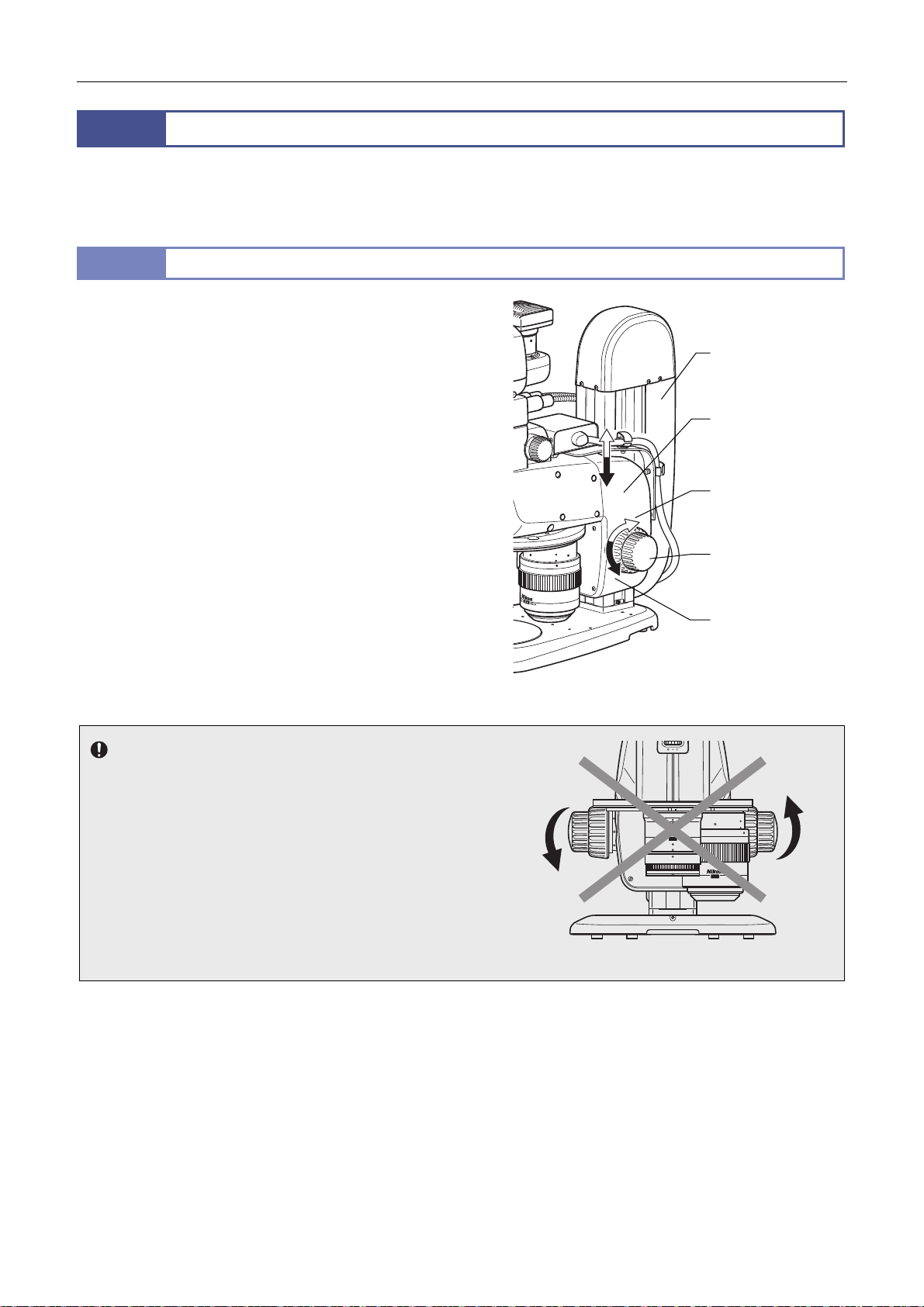
Chapter 4 Functions and Operations of the Devices
2
The P2-FU Focus Unit having a manual focus knob and the P2-MFU Motorized Focus Unit are available as focusing devices.
In addition, the P2-FMDN Focus Mount is available for focus operations, and is attached to the support of the P-PS32 Plain
Stand.
2.1
The P2-FU Focus Unit consists of a square-type support and a
focus mount with the coaxial coarse/fine focusing system. The
focus mount is attached with the SMZ18 or SMZ25 Zooming Body
through the P2-RNI2 Intelligent Nosepiece or the P2-FM Focus
Mount Adapter. The square support is attached with the P2-PB
Plain Base, P2-DBL LED Diascopic Illumination Base or the
P2-DBF Fiber Diascopic Illumination Base. Three types of stands
can be configured.
Focus can be adjusted using the coarse/fine focus knobs on the
right and left of the focus mount. The figure shows the turning
directions of the focus knob and the corresponding vertical
movements of the focus mount.
Turning the knob backward: Upward movement
Turning the knob forward: Downward movement
Focusing stroke: 100 mm
Stroke per rotation of the focus knob:
Coarse control, 18.50 mm/rotation
Fine control, 3.27 mm/rotation
Notes on turning the focus knobs
Do not turn (or twist) the right and left focus knobs in opposite
directions at the same time. Doing so may cause malfunction.
When the focus knobs reach their rotational limits for the unit's
vertical movement, do not forcibly turn it further. Doing so may
cause malfunction.
Focus Units
P2-FU Focus Unit
P2-FU Focus Unit
(square support)
P2-FU Focus Unit
(focus mount)
Upward movement
Focus knob
(inner: coarse control/
outer: fine control)
Downward movement
P2-FU Focus Unit
1 x
SHR Plan apo WD:60
2 x
SHR Plan apo WD:20
41
Do not turn the knobs in the opposite direction!
Page 56
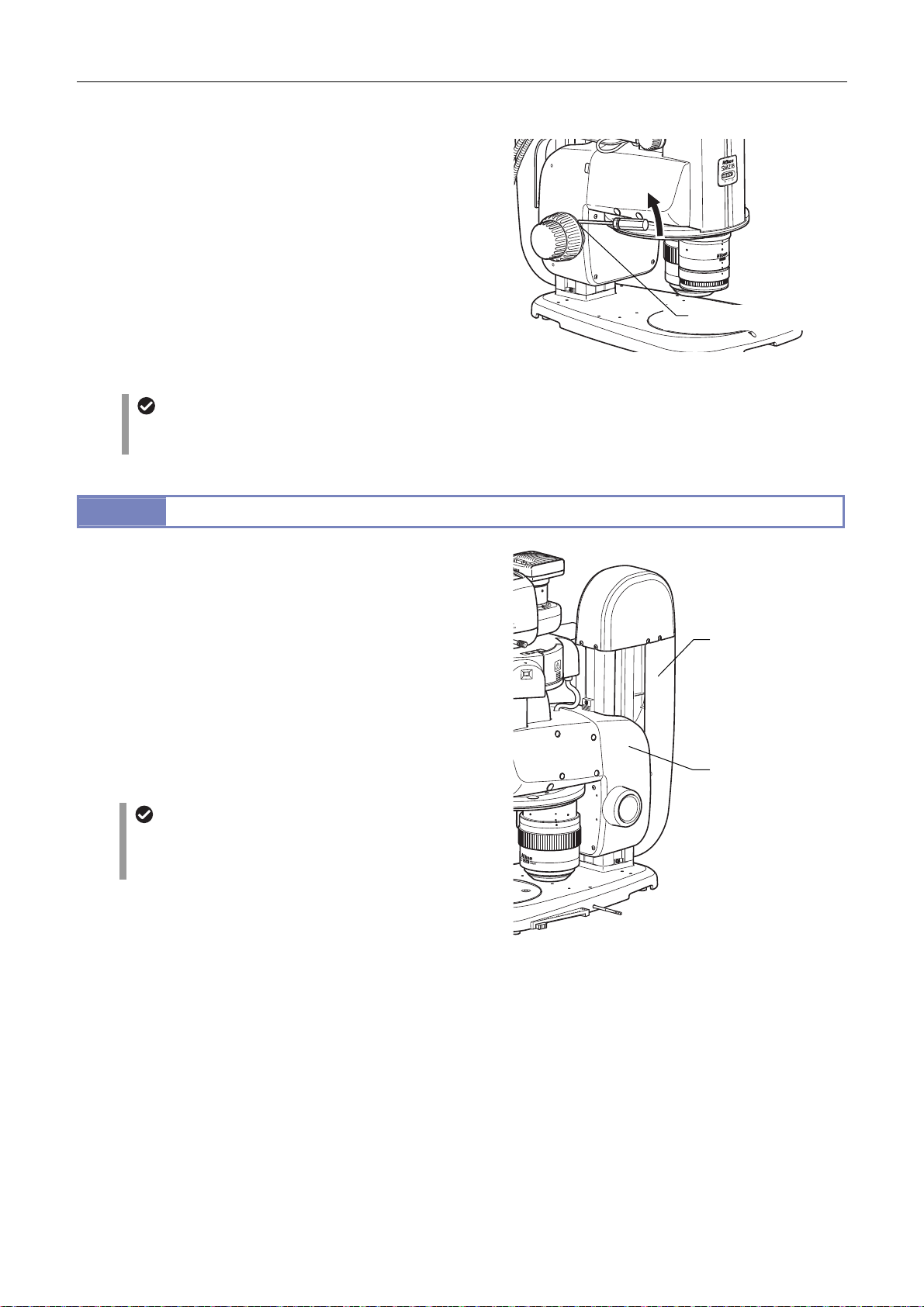
Chapter 4 Functions and Operations of the Devices
Torque of the focus knobs
The torque of the coarse control knobs can be changed by
turning the torque adjustment ring on the base of the left
coarse focus knob using a hex driver (nominal designation, 2:
supplied with the focus unit). When the torque is too low, the
vertical position of the zooming body may slide due to various
loads (such as its own weight or the load of the
counterbalance spring inside the focus unit). Be sure to adjust
the torque to an appropriate level. Note that turning the fine
control knob will cause the coarse control knob to also turn,
changing the torque of the fine control knob.
2.2
The P2-MFU Motorized Focus Unit consists of a square-type
support and a focus mount with the motorized focusing system.
The focus mount is attached with the SMZ18 or SMZ25 Zooming
Body through the P2-RNI2 Intelligent Nosepiece or the P2-FM
Focus Mount Adapter. The square support is attached with the
P2-PB Plain Base, P2-DBL LED Diascopic Illumination Base or
the P2-DBF Fiber Diascopic Illumination Base. Three types of
motorized stands can be configured.
Focusing movement of the motorized focus unit is conducted
using the focus knobs on the remote controller or the foot switch
connected to the remote controller. The vertical position (Z
coordinate value) is shown on the LCD on the remote controller.
Tool storage space
The focus unit has a storage space for storing three tools on its rear side. A hex driver and wrench supplied with the focus
unit and the Intelligent nosepiece can be stored here.
P2-MFU Motorized Focus Unit
Z coordinate value
The accuracy of the Z coordinate value (vertical position)
shown on the remote controller is not guaranteed. This
value is used as a reference and includes a margin error.
2
Increase
WD:60
1x
Apo
n
a
l
P
SHR
Torque adjustment ring
Adjusting the torque of the focus knobs
P2-MFU Motorized
Focus Unit
(square support)
P2-MFU Motorized
Focus Unit
(focus mount)
P2-MFU Motorized Focus Unit
Initialization at power on
When the microscope system has been assembled and the power of the control box is turned on, the motorized focus
unit is initialized as follows:
1 The power is turned on.
2 The focus mount moves upward to the upper limit.
3 The focus mount moves downward to the position before the power was turned on.
42
Page 57
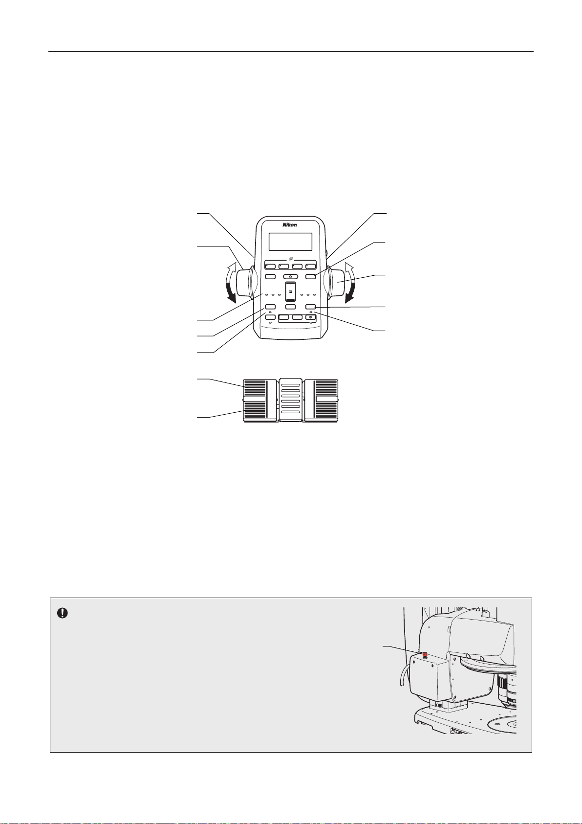
Chapter 4 Functions and Operations of the Devices
1 2 3 4
DISPLAY
BRIGHTNESS
ESCAPE
ALZ
LIMIT
ZOOM
STEP
Z-RESET
Z-SPEED
ZOOM STEP
Coarse
FL Cube
ON/OFF
ON/OFF
ON/OFF
ON/OFF
Fine
Ex Fine1x1x
0.5x
0.1x
r
r
Focus knobs on the remote controller
Turning the knob backward: Upward movement of the focus mount
Turning the knob forward: Downward movement of the focus mount
Focusing stroke: 100 mm
Pedals of the foot switch
Left rear pedal: Upward movement of the focus mount
Left front pedal: Downward movement of the focus mount
For details about the pedal operations, see “10.2 AZ-FSW Foot Switch” in this chapter.
Fine/coarse focus
switching button
Fine/coarse focus
switching button
Focus knob
Upward movement
Downward movement
Focus speed indicato
Escape button
Escape ON/OFF indicato
Left rear pedal
(Upward movement)
Left front pedal
(Downward movement)
Focus speed
The focus speed can be switched between coarse, fine, and extra fine control.
Use the fine/coarse focus switching button on the remote controller to switch the speed.
Each time the button is pressed, the focus speed is cyclically switched in the order of coarse, fine, and extra fine.
When the focus speed is changed, the corresponding indicator (Coarse/Fine/ExFine) lights.
Coarse: 2 to 10 mm/second
Fine: 0.2 to 5 mm/second
Extra fine: 0.01 to 0.1 mm/second
Forced stop of motorized movement
The motorized focus unit is equipped with the STOP switch on the
left side. Pressing the switch causes motorized movement to be
forcibly stopped. To resume the motorized movement, perform the
following steps:
1. Press the STOP switch again.
2. Turn off the power by pressing the power switch of the
P2-CTLB Control Box to the “” position.
3. Turn on the power by pressing the power switch to the “|”
position. (After the power on, initialization at power on is
automatically performed.)
FL Cube
DISPLAY
Z-SPEED
Coarse
Fine
Ex Fine
ESCAPE
ON/OFF
ALZ
ON/OFF
+
−
ZOOM
STEP
−+
ZOOM STEP
Z-RESET
0.5x
0.1x
LIMIT
ON/OFF
ON/OFF
Focus operation
43
BRIGHTNESS
STOP switch
Z-reset button
Focus knob
Limit button
Limit ON/OFF indicator
Page 58

Chapter 4 Functions and Operations of the Devices
Focus knob of the P2-MFU Motorized Focus Unit
The focus knob of the P2-MFU Motorized Focus Unit attached with a cover cannot be used. This knob is to be used by Nikon
during maintenance.
Useful focus operation functions
The P2-MFU Motorized Focus Unit enables operations such as setting the limit position, setting retracting, and resetting Z
using the remote controller.
Limit position setting
When the limit button is pressed, the current position is set as the limit position so that the vertical movement part does
not move down passing the limit point.
Pressing the limit button again cancels the limit position setting. When a limit position is set, the limit ON/OFF indicator
below the button lights. Note that a limit position cannot be set in the range from the upper limit to 10 mm below that
position. The default value of the limit position setting is 0 mm. The setting value can be changed using the NIS-Elements
of remote controller.
Escape setting
Pressing the Escape button causes the vertical movement part to move upward by the preset distance so that it stays in
position. The vertical movement is not possible in this escape status. Pressing the Escape button again causes the
vertical movement part to return to the previous position. Pressing and holding the Escape button causes the vertical
movement part to exit escape status. When in escape status, the Escape ON/OFF indicator below the button lights.
The default value of the escape setting is 20 mm. The setting value can be changed using the setup tool or
NIS-Elements.
Z resetting
Pressing the Z-reset button displays 0 as the Z position (focus position) on the LCD of the remote controller. Pressing the
button at another position sets that position as 0.
Also see “10.1 P2-RC Remote Controller” in this chapter.
Tool storage space
The focus unit has a storage space for storing three tools on its rear side. A hex driver and wrench supplied with the focus
unit and the Intelligent nosepiece can be stored here.
44
Page 59
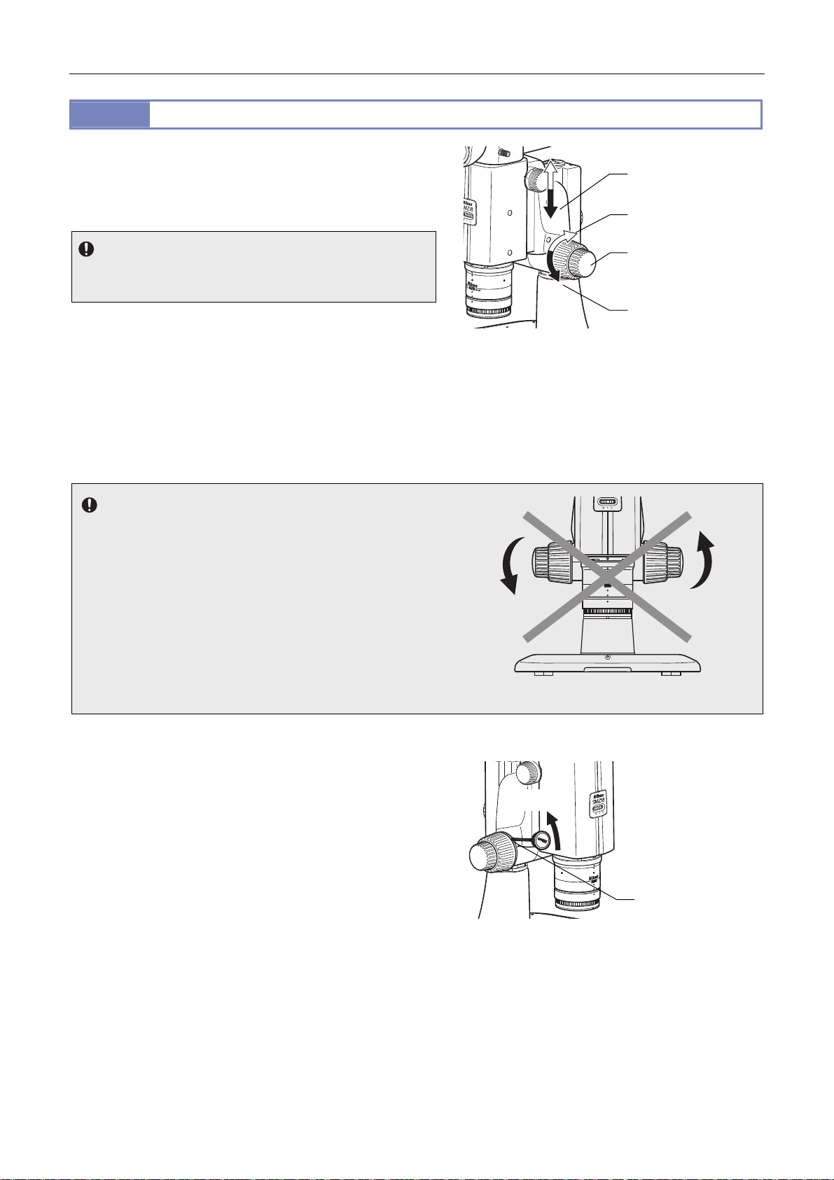
Chapter 4 Functions and Operations of the Devices
A
2.3
The P2-FMDN Focus Mount is used exclusively for the SMZ18.
djust the focus using the focus knob.
The focus mount can be attached to various stands having a
support of 32 mm diameter.
P2-FMDN Focus Mount
Focus mount
Upward movement
Usage restriction
This focus mount cannot be combined and used with the P2-EFLM
Motorized Epi Fluorescence Attachment.
The figure shows the turning directions of the focus knob and the
corresponding vertical movements of the focus mount.
Turning the knob backward: Upward movement
Turning the knob forward: Downward movement
Focusing stroke: 65 mm
Stroke per rotation of the focus knob:
Coarse control, 18.50 mm/rotation
Fine control, 3.27 mm/rotation
Notes on turning the focus knobs
Do not turn (or twist) the right and left focus knobs in opposite
directions at the same time. Doing so may cause malfunction.
When the focus knobs reach their rotational limits for the unit’s
vertical movement, do not forcibly turn it further. Doing so may
cause malfunction.
Focus knob
(inner: coarse control/
outer: fine control)
Downward movement
P2-FMDN Focus Mount
1 x
SHR Plan apo WD:60
Torque of the focus knobs
The torque of the coarse control knobs can be changed by
turning the torque adjustment ring on the base of the left
coarse focus knob using the tool supplied with the stand.
When the torque is too low, the vertical position of the
zooming body may slide due to various loads (such as its own
weight or the load of the counterbalance spring inside the
focus unit). Be sure to adjust the torque to an appropriate
level. Note that turning the fine control knob will cause the
coarse control knob to also turn, changing the torque of the
fine control knob.
Do not turn the knobs in the opposite direction!
0.75
1
2
Increase
WD:60
1x
Apo
n
a
l
P
SHR
Torque adjustment
ring
Adjusting the torque of the focus knobs
45
Page 60
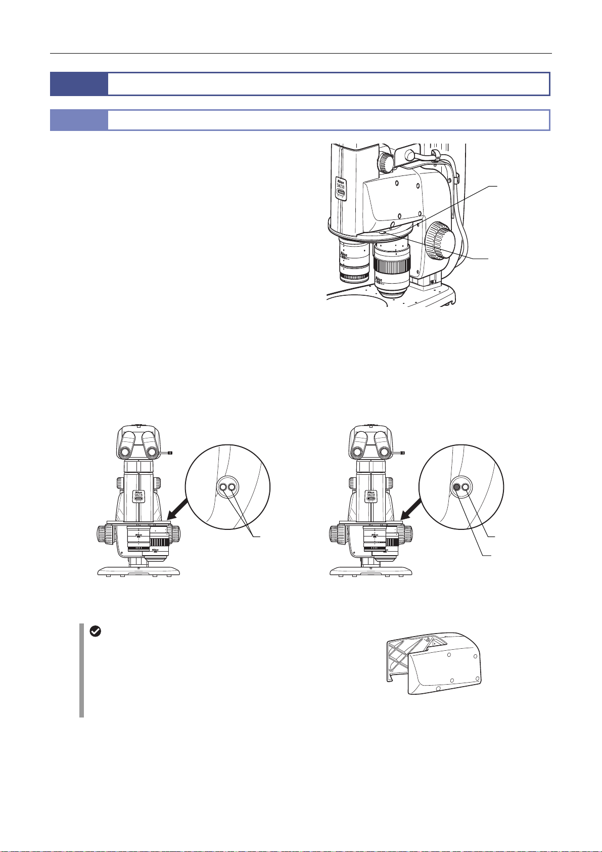
Chapter 4 Functions and Operations of the Devices
3
3.1
The P2-RNI2 Intelligent Nosepiece can be attached with two
objectives. The attached objectives can be switched by turning
the nosepiece.
■ Stereoscopic view and vertical view
An intelligent nosepiece has two click positions for each
objective.
The click position switches between stereoscopic view and
vertical view. Microscopy with vertical view is possible when
needed, for example when taking a picture.
The click position of the objective can be checked by the
position of the objective viewed from the front or the color of
the hole on the objective status display area on the intelligent
nosepiece.
For systems where a control box has been connected, the
objective attachment position addresses and vertical-view state
are sent to the control box via a motorized focus unit or relay box,
and then transmitted to the DS-L3 DS Camera Control Unit and
personal computer.
Nosepiece
P2-RNI2 Intelligent Nosepiece
Objective state
indication
Nosepiece
Objective state
indication
P2-RNI2 Intelligent Nosepiece
Objective state
indication
SHR Plan apo WD:60
1 x
2 x
SHR Plan apo WD:20
White White
SHR Plan apo WD:60
1 x
SHR Plan apo WD:20
2 x
Stereoscopic view Vertical view
Objective position state (stereoscopic view and vertical view)
P2-FM Focus Mount Adapter
The P2-RNI2 Intelligent Nosepiece also serves as the
interface between the zooming body and focus unit. To
connect the zooming body with the focus unit, the P2-FM
Focus Mount Adapter must be connected.
P2-FM Focus Mount Adapter
46
Black
Page 61
Chapter 4 Functions and Operations of the Devices
4
The microscope system supports the following objectives.
Attach the objectives to the zooming body or intelligent nosepiece.
Model name P2-SHR Plan Apo 0.5X P2-SHR Plan Apo 1X P2-SHR Plan Apo 1.6X P2-SHR Plan Apo 2X
Magnification 0.5x 1x 1.6x 2x
Objectives
Numerical
aperture
(maximum)
Working
distance
Parfocal
distance:
Objective mount Exclusively-shaped
Others Protection ring provided Correction glass
0.078 0.156 0.25 0.312
71 mm 60 mm 30 mm 20 mm
150 mm 150 mm 150 mm 150 mm
bayonet
Exclusively-shaped
bayonet
provided
Exclusively-shaped
bayonet
With a correction ring
Exclusively-shaped
bayonet
The 2x objective is equipped with the correction ring for water 0 to 3 mm in depth. The correction ring compensates an
aberration caused by water in the dish. With this objective, select 2x magnification or higher. If magnification less than 2x
is selected, shading will occur or part of the field of view will be missing.
Attach the 1/4 lambda plate supplied with the coaxial epi illuminator to the position from which the protection ring supplied
with the 0.5x objective or the correction glass supplied with the 1x objective has been removed.
Usage restriction
When the episcopic illuminator is used, use of the objectives and magnification are subject to some restrictions.
(See “7 Episcopic Illuminator” in this chapter.)
When the diascopic illuminator is used, use of the objectives and magnification are subject to some restrictions.
(See “8 Diascopic Illuminator” in this chapter.)
Total magnification
The total magnification of the microscope is determined from the formula below:
Total magnification = zoom magnification x objective’s magnification x eyepiece’s magnification
When using a vertical tube, replace the eyepiece’s magnification with the C mount adapter lens’ magnification to
calculate the total magnification.
47
Page 62
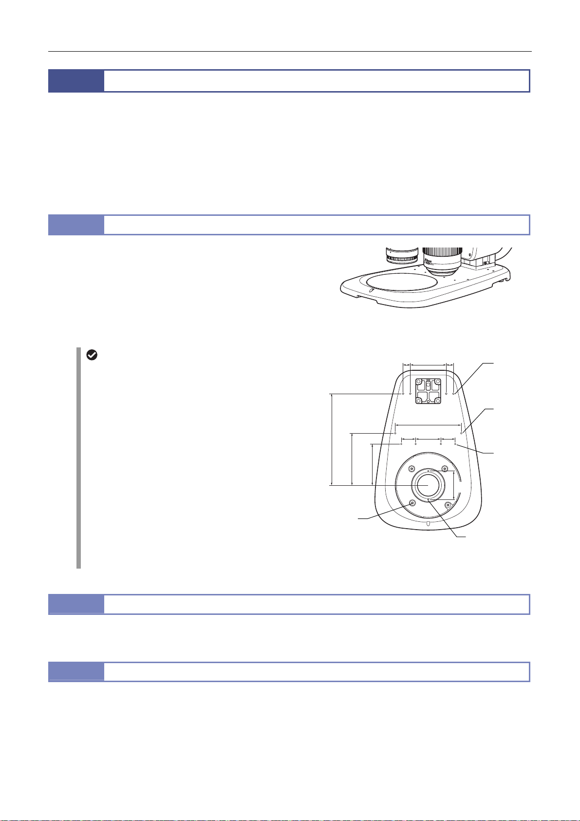
Chapter 4 Functions and Operations of the Devices
5
Bases consist of various focus stands in combination with the focus units. The base models include a base without a built-in
diascopic illumination system and a base with a built-in optical system for diascopic illumination.
A stand type is also available where a focus mount is connected to the support of the stand.
In all cases, a large stage plate (180 mm dia.) is used to enable more efficient work and easier observation of samples in
containers such as petri dishes.
The stage plate can be replaced with a stage having an X/Y shift knob or a sliding stage. It is also possible to attach other
devices such as a fiber illuminator or diascopic polarizing device to expand the base’s functions.
5.1
The plain base consists of a plain stand or a motorized plain stand
in combination with the P2-FU Focus Unit or P2-MFU Motorized
Focus Unit.
It is equipped with a stage plate having black and milky white
planes. Select the plain based on the sample being observed.
The plain base has three indents for holding the base: front of the
base’s top board and on the right and left rear.
5.2
See “8.1 P2-DBL LED Diascopic Illumination Base” in this chapter.
5.3
See “8.2 P2-DBF Fiber Diascopic Illumination Base” in this chapter.
Bases, Stand, and Stages
P2-PB Plain Base
Tap holes for attaching accessories
The base’s top board has tap holes for attaching various
accessories. Tap holes
prevent ingress of solution into the base.
(1) 2-M4: Positioned under the stage plate attachment
section of the base. Used for multiple
purposes.
(2) 4-M6: Positioned under the stage plate attachment
section of the base, Used for attaching the
P-SXY64 XY Stage.
(3) 2-M5: Positioned at the center on the top surface of
the base. Used for multiple purposes.
(4) 4-M4: Positioned at the center on the top surface of
the base. Used for multiple purposes.
(5) 4-M5: Positioned at the rear on the top surface of the
base. Used for attaching an accessory such as
the C-FDF Flexible Double Arm Fiber
Illumination Unit.
P2-DBL LED Diascopic Illumination Base
P2-DBF Fiber Diascopic Illumination Base
(2) to (5) are not penetrating to
P2-PB Plain Base
255
145
115
(2)
4-M6
Depth 8
Tap holes for attaching accessories
20 100 20
184
40 70 40
(5)
4-M5
Depth 7
(3)
2-M5
Depth 7
(4)
4-M4
Depth 6
80
(1)
2-M4
48
Page 63
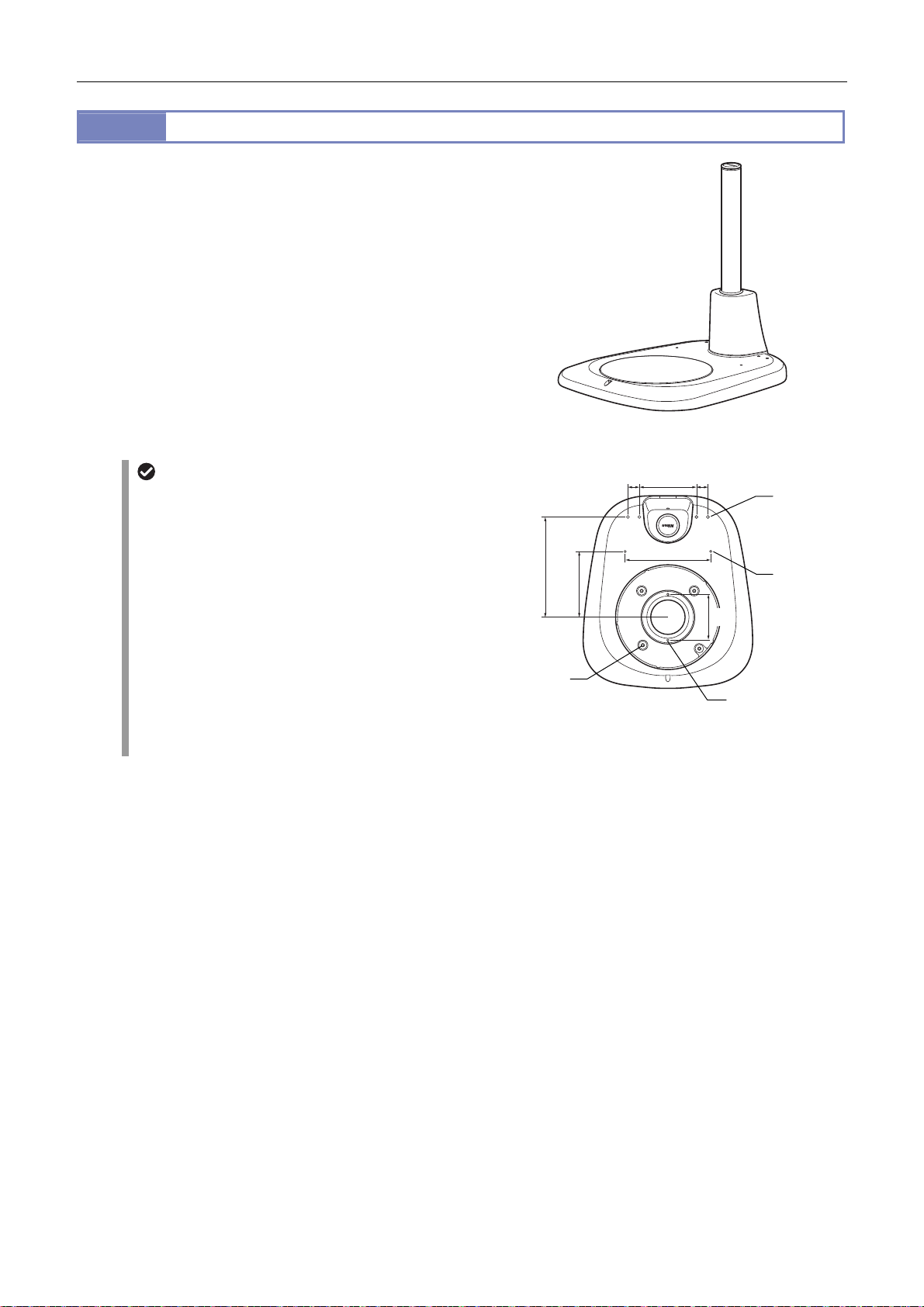
Chapter 4 Functions and Operations of the Devices
5.4
This stand consists of a microscope system with the SMZ18
Zooming Body attached with the P2-FMDN Focus Mount.
It is equipped with a stage plate having black and milky white
planes. Select the plane based on the sample being observed.
The stand support can be replaced with a long support. A special
screwdriver is stored in the upper part of the support.
P-PS32 Plain Stand
Tap holes for attaching accessories
The base’s top board has tap holes for attaching various
accessories. The tap holes are not penetrating to prevent
ingress of solution into the base.
(1) 2-M4: Positioned under the stage plate attachment
part of the base. Used for multiple purposes.
(2) 4-M6: Positioned under the stage plate attachment
part of the base. Used for attaching the
P-SXY64 XY Stage.
(3) 2-M4: Positioned at the center on the top surface of
the base. Used for multiple purposes.
(4) 4-M5: Positioned at the rear on the top surface of the
base. Used for attaching an accessory such as
the C-FDF Flexible Double Arm Fiber
Illumination Unit.
P-PS32 Plain Stand
20 100 20
150
175
115
(2)
4-M6
Depth 8
Tap holes for attaching accessories
80
(4)
4-M5
Depth 7
(3)
2-M4
Depth 6
(1)
2-M4
49
Page 64
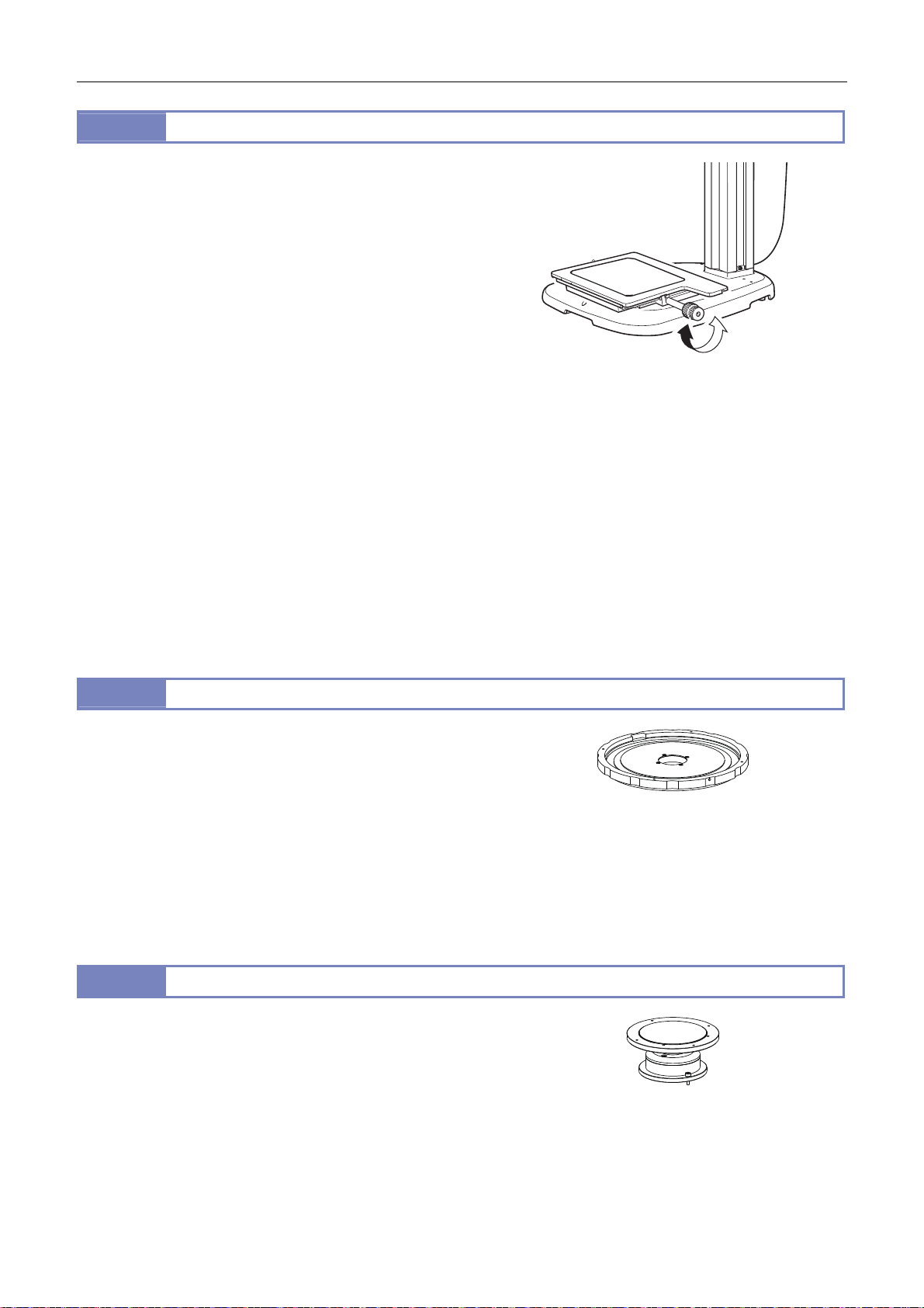
Chapter 4 Functions and Operations of the Devices
A
5.5
This stage shifts the glass plate in the X and Y directions when
the X/Y shift knobs are turned. Attach this stage instead of the
base or the stage plate on the stand. The glass plate measures
215 mm x 154 mm x 5 mm and is detachable.
45-mm dia. filter can be slotted into the optical-path hole on the
lower board of the stage.
[Compatible bases and stand]
P2-PB Plain Base
P2-DBL LED Diascopic Illumination Base
P2-DBF Fiber Diascopic Illumination Base
P-PS32 Plain Stand
(The movement of the stroke in the Y direction is restricted.)
XY stroke of the stage with the X/Y shift knob and stroke per rotation of the knob
X: 150 mm; 37.5 mm per rotation
Y: 100 mm; 24.1 mm per rotation
P-SXY64 XY Stage
Shift using the P-SXY64 XY Stage
Load weight
5 kg or less
Applicable range of diascopic illumination (bright field/ OCC)
150 x 100 mm travel range (Shading may occur in diascopic illumination or OCC illumination in the low zoom
magnification range.)
5.6
This stage enables fine movement of a sample when its side is
pushed.
Remove the stage plate of the base and attach it to the upper surface
of the sliding stage. Then, mount the sliding stage to the base.
[Compatible bases]
P2-PB Plain Base
P2-DBL LED Diascopic Illumination Base
P2-DBF Fiber Diascopic Illumination Base
P-PS32 Plain Stand
5.7
This stage enables tilt observation of samples. Attach the stage to
the base or stand.
For details about usage, refer to the instruction manual for the
C-TRS Tilting Stage.
[Compatible bases and stand]
P2-PB Plain Base
P2-DBL LED Diascopic Illumination Base
P2-DBF Fiber Diascopic Illumination Base
P-PS32 Plain Stand
C-SSL DIA Sliding Stage
C-TRS Tilting Stage
C-SSL DIA Sliding Stage
C-TRS Tilting Stage
50
Page 65
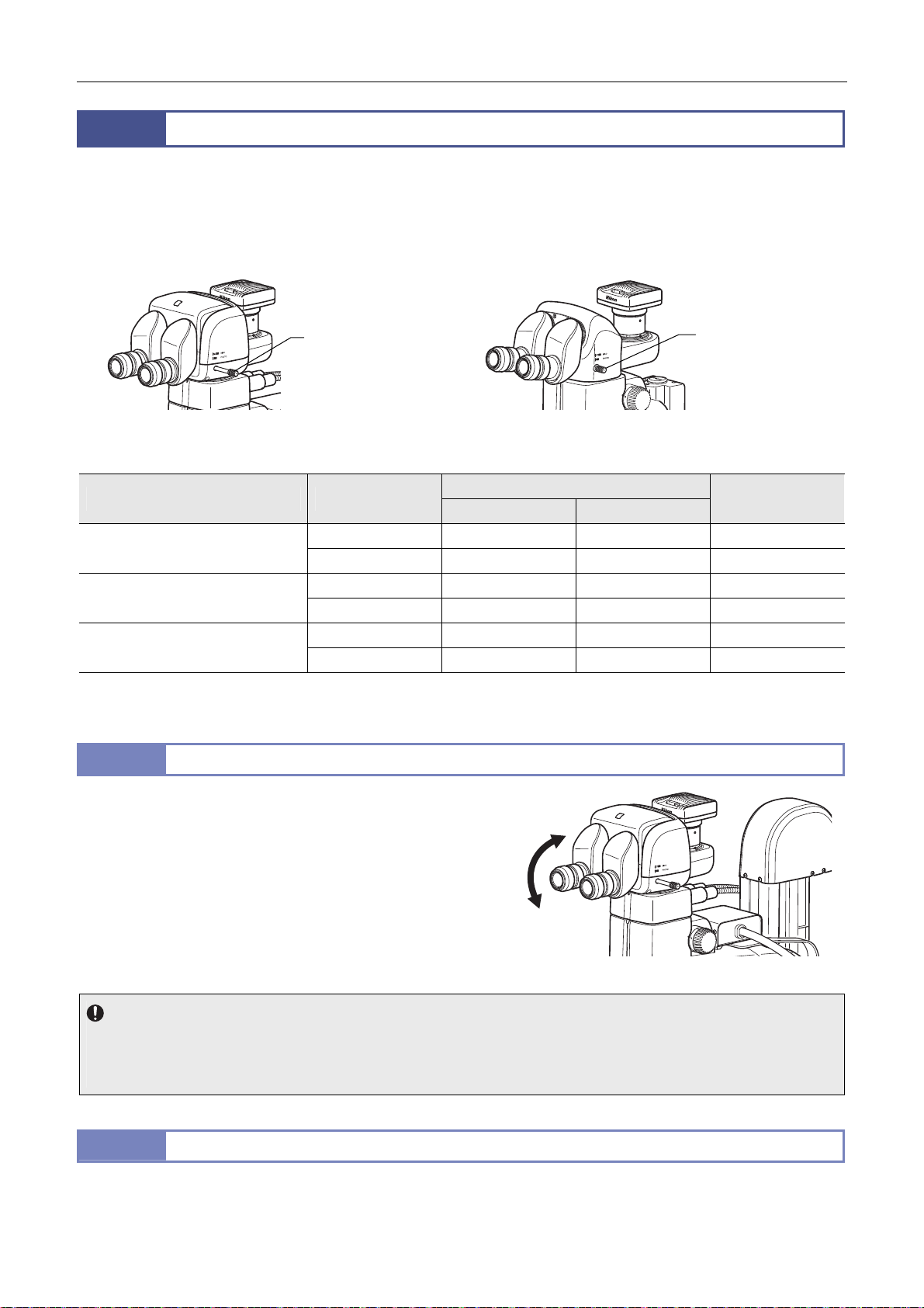
Chapter 4 Functions and Operations of the Devices
A
A
A
6
This microscope system can be used with the tubes listed in the table below.
Attach the 10x, 15x, 20x, or 30x eyepiece to the binocular sleeve. Then, attach a camera such as a DS camera head to the
vertical tube using an adapter.
The tube is equipped with the optical path switching lever. This allows the optical path to be switched during observation using
the eyepiece and capture images using the DS camera. The distribution ratio of the light amount depends on the tube type.
Tubes
Optical path
switching lever
P2-TERG 100/ P2-TERG 50 Trinocular Tilting Tube
P2-TL100 Trinocular Tube L
Optical path
switching lever
Distribution of light with optical path switching (%)
Tube Lever position
P2-TERG 100 Trinocular Tilting
Tube
P2-TERG 50 Trinocular Tilting Tube Pulled out 100 100 0
P2-TL100 Trinocular Tube L Pulled out 100 100 0
* The light amount of the left eye is always 100%. The light from the optical path of the right eye is diverged to the vertical tube. (An
image in the right eye’s optical path is captured.)
Pulled out 100 100 0
Pushed in 100 0 100
Pushed in 100 50 50
Pushed in 100 0 100
Binocular part
Left Right
Vertical tube*
6.1
This is an ergonomic tube that enables the angle of depression to
P2-TERG 100/ P2-TERG 50 Trinocular Tilting Tube
be adjusted.
The angle can be continuously changed by moving the binocular
part as indicated by the arrow in the figure.
djust the angle to facilitate microscopy.
The eye level can be changed also by turning the binocular part 180°.
ngle of depression: 0 to 30° (continuously variable)
For the division of the light amount with the optical path switching
lever, see the table above.
djusting the angle of depression
Notes on adjusting the angle of depression
Do not apply excessive force to the binocular part during depression angle adjustment. It may cause unexpected failure or
malfunction.
When moving the binocular part, be careful not to catch your fingers in the rotary section at the bottom of the binocular part.
6.2
P2-TL100 Trinocular Tube L
Angle of depression: 10°
For the distribution ratio of the light amount with the optical path switching lever, see the table above.
51
Page 66
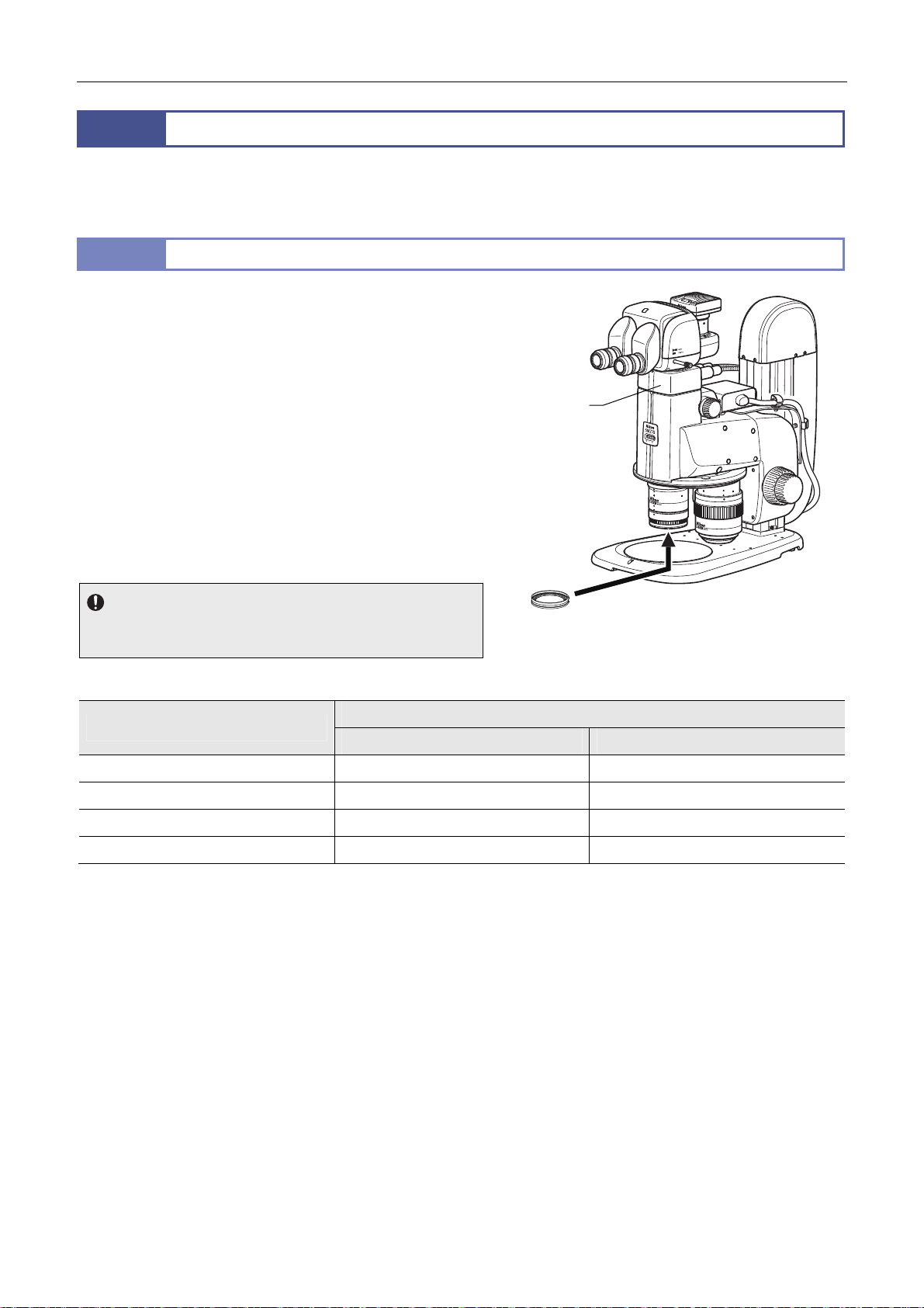
Chapter 4 Functions and Operations of the Devices
A
A
r
7
The illuminators which can be used for this microscope system include a coaxial episcopic illuminator, which is attached
between the zooming body and tube, a ring fiber illuminator, which is attached to the tip of the objective, and an illuminator
that has a flexible fiber for adjusting the illumination direction.
7.1
ttach this illuminator to the position between the zooming body
and the tube. The C-FLED2 LED Light Source for Fiber
Illuminator is used as its light source. The light from the light
source is led into the device by the two-branch fiber and episcopic
illumination is generated along the optical axis. This illuminator is
suitable for observing mirror-like samples.
1/4 λ plate is supplied with the illuminator to prevent flare at the
imaging system due to light reflected in the optical system. Attach
the plate to the tip of the 0.5x or 1x objective.
Before attaching the plate, remove the protection ring from the tip
of the 0.5x objective, and remove the correction ring from the tip
of the 1x objective.
The brightest illumination is generated when the while-circle
indicator is at the front. Select a position that has the optimum
brightness and contrast for observation.
Usage restriction
The type of objectives used for the coaxial epi illuminator and the
recommended zoom magnification are shown below.
Episcopic Illuminator
P2-CI Coaxial Epi Illuminator
Coaxial epi
illuminato
1/4 λ plate
P2-CI Coaxial Epi Illuminator
Compatible objectives and recommended zoom magnification
Objective
SMZ18 Zooming Body SMZ25 Zooming Body
P2-SHR Plan Apo 0.5X 3.8x - 2.5x -
P2-SHR Plan Apo 1X 4x - 4x -
P2-SHR Plan Apo 1.6X Unusable Unusable
P2-SHR Plan Apo 2X Unusable Unusable
* Shading or vignetting may occur in the low zoom magnification range.
Zoom magnification
For details about using the light source, refer to the instruction manual for the light source.
52
Page 67

Chapter 4 Functions and Operations of the Devices
r
r
7.2
This illuminator is a fiber connected to the C-FLED2 LED Light
Source for Fiber Illuminator for illuminating samples.
Two fibers are held by the C-FIDH Fiber Holder. The orientation of
the holder’s arm can be adjusted so that the tips of the fibers face
the samples for illumination. For details about using the fiber
holder, see the “ C-FIDH Fiber Holder” on the next page.
Important notes on handling the fibers
Do not excessively bend the fibers or apply excess force to the
fibers. Doing so may damage the fibers.
For details about using the light source, refer to the instruction
manual for the light source.
C-FIDH Fiber Holder
It holds the tip of the flexible double-arm fiber. Mount the base of
the holder to the base (stand) of the microscope system. It holds
the tips of the fibers with the two arms coming from the holder’s
base. The arms can be freely positioned in any direction. The
positions of the arms can be firmly locked by tightening the knobs
at the joints of the arms. The arms are connected with a
mechanism that enables the arms to be freely swung centered
around a single axis (Z axis). This allows the arms to be pushed
aside without having to unlock the arm joints. After that, if the arm
position is returned by the rotation of the single axis, the arm will
stop at the position that was locked first.
7.3
This illuminator is connected to the C-FLED2 LED Light Source
for Fiber Illuminator. Attach the ring-shaped fiber illumination to
the outer periphery of the objective in order to illuminate samples.
The edge face of the sample can be illuminated evenly using this
ring-shaped fiber.
Usage restriction
The following two objectives can be used with the P2-FIR Ring
Fiber Illumination Unit:
P2-SHR Plan Apo 0.5X
P2-SHR Plan Apo 1X
Important notes on handling the fibers
Do not excessively bend the fibers or apply excess force to the
fibers. Doing so may damage the fibers.
For details about using of the light source, refer to the instruction
manual for the light source.
7.4
The ring illumination part is attached to the outer periphery in order to illuminate samples.
For details, refer to the instruction manual for the P2-FIRL LED Ring Illumination Unit.
C-FDF Flexible Double Arm Fiber Illumination Unit
C-FDF Flexible Double Arm Fiber illumination Unit
P2-FIR Ring Fiber Illumination Unit
P2-FIRL LED Ring Illumination Unit
Fibe
Apo
1 x
WD:60
Apo
2 x
WD:20
Fiber holde
(knob)
C-FIDH Fiber Holder
P2-FIR Ring Fiber Illumination Unit
To C-FLED2 LED
Light Source for
Fiber Illuminator
Fiber holder
(single-axis
rotary section)
To C-FLED2 LED
Light Source for
Fiber Illuminator
53
Page 68
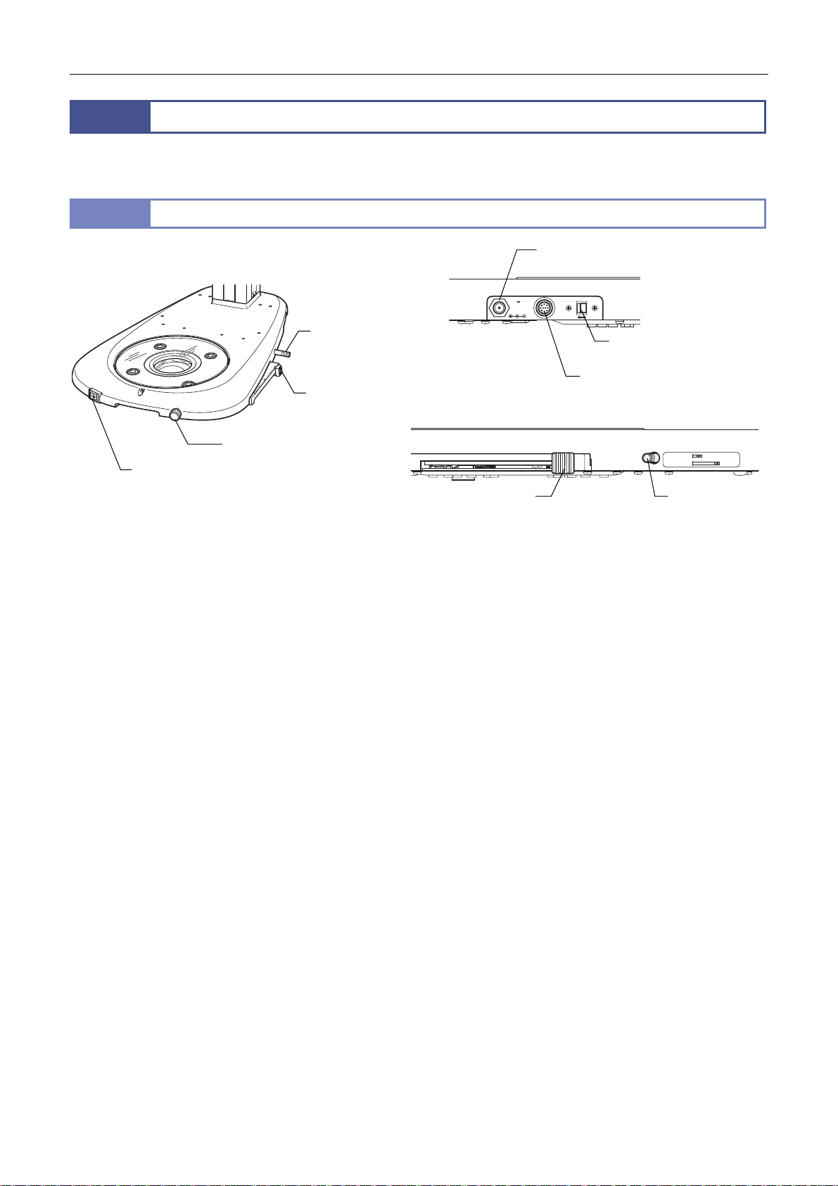
Chapter 4 Functions and Operations of the Devices
A
r
8
The primary diascopic illuminator for this microscope system consists of an illumination base equipped with an illuminating
optical system. A dark-field illuminator and polarizing illuminator are also available.
8.1
Diascopic Illuminator
P2-DBL LED Diascopic Illumination Base
Prism sheet
IN/OUT lever
OCC adjustment
knob
LED brightness control
selection switch
INPUT
12VDC ,
3.5A
CTRL
CTRL
ON OFF
LED brightness
control terminal
C adapter input terminal
Left side
LED power source ON/OFF switch
LED light control dial
P2-DBL LED Diascopic Illumination Base
OCC adjustment knob
Right side
1.6-2x
0.5-1x
Prism sheet
IN/OUT leve
IN
OUT
This illumination base contains an optical system for diascopic illumination. Since the base supports OCC illumination,
high-contrast observation of transparent samples is enabled.
The control box supplies the power for illumination control if the control box is connected. Otherwise, a 12 V AC adapter must
be connected.
To turn on illumination, move the LED power ON/OFF switch on the front of the base to the “|” (ON) position. Use the LED
brightness control dial to adjust the brightness. Turn the LED brightness control dial clockwise to increase the brightness as
needed.
If the control box is connected, LED On/Off, brightness control, and light intensity monitoring are possible using the control
box by assigning the illumination control right to the control box. Use the brightness control selection switch on the base to
assign the control right to the base or to the control box.
Brightness control selection switch Off: Assigns the control right to the base.
Brightness control selection switch On: Assigns the control right to the control box.
The stage plate of the base is large (180 mm dia.) and made of transparent glass to enable more efficient work and easier
observation of samples in containers such as petri dishes. The base has three indents for holding the base: front of the
base’s top board and on the right and left rear.
The stage plate can be replaced with a stage having an X/Y shift knob or a sliding stage. It is also possible to attach other
devices such as a fiber illuminator or diascopic polarizing device to expand the base’s functions.
OCC (oblique coherent contrast) illumination
The LED diascopic illumination base supports OCC illumination. OCC illumination is an oblique illumination method for
observing the phase objects, where a sample is illuminated with a coherent illuminating light obliquely by shielding a part
of the optical path using a shading plate. By this illumination method, a colorless transparent sample can be observed
with relief and contrast.
To adjust the OCC contrast, slide the OCC adjustment knob at the right front of the base back and forth. Adjust until the
optimum observation state is obtained in combination with the selected magnification and phase amount of the sample.
For ordinary bright-field microscopy under diascopic illumination, set the OCC adjustment control to either the farthest or
closest position. Sliding the control gradually forward or backward from that position will cause the OCC effect to increase.
Sliding the control by 46 mm will result in completely shielded status. Since adjustment in two directions is thus possible,
the direction of the OCC contrast can be reversed.
In addition, since the adjustment control has a scale, the control position can be reproduced.
54
Page 69
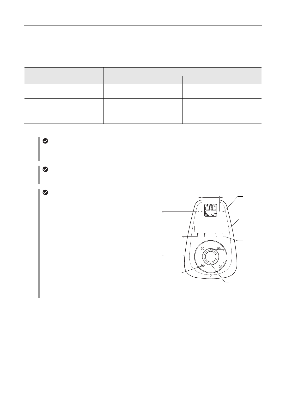
Chapter 4 Functions and Operations of the Devices
Prism sheet
The LED diascopic illumination base contains a prism sheet to reduce shading. When using the 1.6x or 2x objective, push
in the prism sheet IN/OUT lever. When using the 0.5x or 1x objective, pull out the lever.
Compatible objectives and recommended zoom magnification
Objective
P2-SHR Plan Apo 0.5X 1.3x - Contrast in the field of view
P2-SHR Plan Apo 1X Entire area 5.0x-
P2-SHR Plan Apo 1.6X Entire area 4.0x -
P2-SHR Plan Apo 2X 2.0x - 3.0x -
* Shading may occur in the low zoom magnification range.
Increasing contrast of the OCC observation image
For observations of the OCC observation image with higher contrast, remove the filter dropping ring (attached to the base
optical path immediately under the grass plate). The contrast can be increased by removing the filter dropping ring that
contains a diffuser plate to control excess contrast for OCC.
45-mm dia. filter
A 45-mm dia. filter (no thicker than 5 mm) can be dropped onto the filter dropping ring (attached to the base optical path
immediately under the grass plate).
Tap holes for attaching accessories
The base’s top board has tap holes for attaching various
accessories. Tap holes
prevent ingress of solution into the base.
(2) to (5) are not penetrating to
Bright-field diascopic illumination OCC illumination
Zoom magnification
is not uniform.
20 100 20
(1) 2-M4: Positioned under the stage plate attachment
section of the base. Used for multiple
purposes.
(2) 4-M6: Positioned under the stage plate attachment
section of the base. Used for attaching the
P-DF LED Dark Field Unit.
255
145
115
184
40 70 40
(3) 2-M5: Positioned at the center on the top surface of
the base. Used for multiple purposes.
80
(4) 4-M4: Positioned at the center on the top surface of
the base. Used for multiple purposes.
(5) 4-M5: Positioned at the rear on the top surface of the
base. Used for attaching an accessory such as
the C-FDF Flexible Double Arm Fiber
Illumination Unit.
(2)
4-M6
Depth 8
Tap holes for attaching accessories
(1)
2-M4
(5)
4-M5
Depth 7
(3)
2-M5
Depth 7
(4)
4-M4
Depth 6
55
Page 70
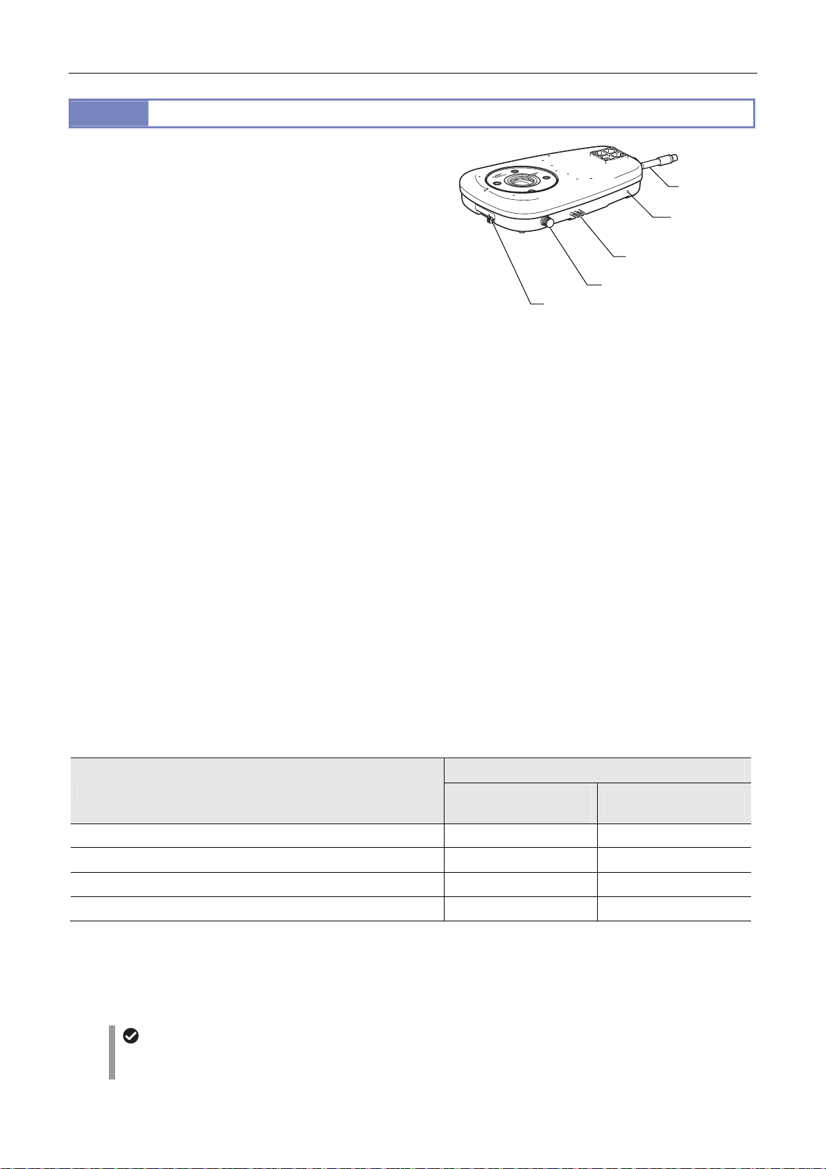
Chapter 4 Functions and Operations of the Devices
8.2
This illumination base contains an optical system for episcopic
illumination. Since the base supports OCC illumination,
high-contrast observation of transparent samples is enabled. The
C-FLED2 LED Light Source for Fiber Illuminator is used as the
light source. The fiber should be connected to the rear side of the
base. For details about using the light source, refer to the
instruction manual for the light source.
The stage plate of the base is large (180 mm dia.) and made of
transparent glass to enable more efficient work and easier
observation of samples in containers such as petri dishes. The
base has three indents for holding the base: front of the base’s
top board and on the right and left rear.
The stage plate can be replaced with a stage having an X/Y shift
knob or a sliding stage. It is also possible to attach other devices
such as a fiber illuminator or diascopic polarizing device to
expand the base’s functions.
OCC (oblique coherent contrast) illumination
The fiber diascopic illumination base supports OCC illumination. OCC illumination is an oblique illumination method for
observing the phase objects, where a sample is illuminated with a coherent illuminating light obliquely by shielding a part
of the optical path using a shading plate. By this illumination method, a colorless, transparent sample can be observed
with relief and contrast.
To adjust the OCC contrast, turn the OCC adjustment knob. Adjust until the optimum observation state is obtained in
combination with the selected magnification and phase amount of the sample. In addition, since the OCC adjustment
knob has a scale, the position of the knob can be reproduced.
P2-DBF Fiber Diascopic Illumination Base
Condenser lens switching lever
Filter IN/OUT lever
OCC adjustment knob
P2-DBF Fiber Diascopic Illumination Base
Fiber
Fiber
fixing screw
Condenser lens
The base contains condenser lenses for low/high-magnification microscopy. Switch the condenser lens based on the
objective being used to ensure uniform diascopic illumination. A wide range of observation magnifications are supported.
To switch the condenser lens, slide the condenser lens switching lever to the right or left.
Slide the lens switching lever to the right: For low magnification; objective lens 0.5x to 1x
Slide the lens switching lever to the left: For high magnification; objective lens 1.6x to 2x
When the condenser lens is switched, the built-in prism sheet is automatically switched and the shading adjusted.
Compatible objectives and recommended zoom magnification
Zoom magnification
Objective
P2-SHR Plan Apo 0.5X plus condenser lens for low magnification 1.5x - 4.5x -
P2-SHR Plan Apo 01X plus condenser lens for low magnification Entire area 4.0x -
P2-SHR Plan Apo 1.6X plus condenser lens for high magnification Entire area 4.0x -
P2-SHR Plan Apo 2X plus condenser lens for high magnification 2.0x - 6.0x-
* Shading may occur in the low zoom magnification range.
Bright-field diascopic
illumination
OCC illumination
Filter
The base has three different filters: NCB11, ND4, and ND16. The individual filters can be inserted into and removed from
the optical path separately. To insert a filter into the optical path, push in the filter IN/OUT lever.
45-mm dia. filter
A 45-mm dia. filter (no thicker than 2 mm) can be dropped onto the filter dropping ring (attached to the base optical path
immediately under the grass plate).
56
Page 71
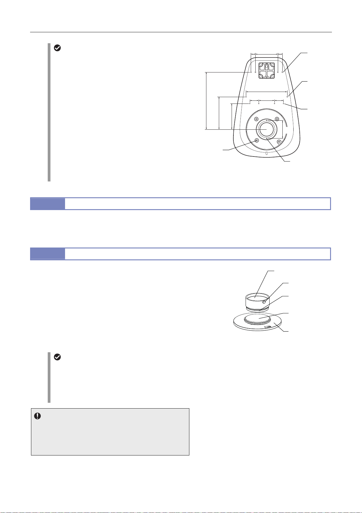
Chapter 4 Functions and Operations of the Devices
A
A
A
A
Tap holes for attaching accessories
The base’s top board has tap holes for attaching various
accessories. Tap holes
prevent ingress of solution into the base.
(2) to (5) are not penetrating to
(1) 2-M4: Positioned under the stage plate attachment
section of the base. Used for multiple
purposes.
(2) 4-M6: Positioned under the stage plate attachment
section of the base. Used for attaching the
P-SXY64 XY Stage.
(3) 2-M5: Positioned at the center on the top surface of
the base. Used for multiple purposes.
20 100 20
(5)
4-M5
Depth 7
(3)
2-M5
Depth 7
(4)
4-M4
Depth 6
255
184
40 70 40
145
115
80
(4) 4-M4: Positioned at the center on the top surface of
the base. Used for multiple purposes.
(5) 4-M5: Positioned at the rear on the top surface of the
base. Used for attaching an accessory such as
the C-FDF Flexible Double Arm Fiber
Illumination Unit.
(2)
4-M6
Depth 8
Tap holes for attaching accessories
(1)
2-M4
8.3
P-DF LED Dark Field Unit
This dark-field illumination unit has LEDs that are tilted and positioned like a ring. The unit is attached to the base of the
microscope. For details, refer to the instruction manual for the P-DF LED Dark Field Unit.
8.4
This is a simple polarizing device that consists of a polarizer unit
and analyzer unit.
First remove the stage glass from the diascopic illumination base.
ttach the base plate of the polarizer unit, orient the polarizer as
required, and then set the 90 mm dia-stage glass supplied with
the device. The stage glass can be rotated. Attach the analyzer to
the tip of the objective and tighten the clamp screw to stabilize it.
To turn the analyzer, turn the knurled ring at the tip of the
objective. The polarizer and analyzer have indicators which show
the orientation of the polarizing plate.
P2-POL Simple Polarizing Attachment
Directly placing the polarizer
When the LED diascopic illumination base is in use, the
polarizer can be removed from the polarizer attachment
and can be individually attached to the diascopic
illumination base. Fit it under the stage plate of the
diascopic illumination base. The stage plate can be used as
is.
nalyzer unit
Polarizer unit
nalyzer
Clamp screw
nalyzer
rotating dial
Polarizer
Base plate
P2-POL Simple Polarizing Attachment
Usage restriction
Objectives P2-SHR Plan Apo 1.6x and 2x are not compatible.
The objective P2-SHR Plan Apo 1x covers the entire zoom area.
The objective P2-SHR Plan Apo 0.5x covers a 1x or larger zoom
area.
57
Page 72
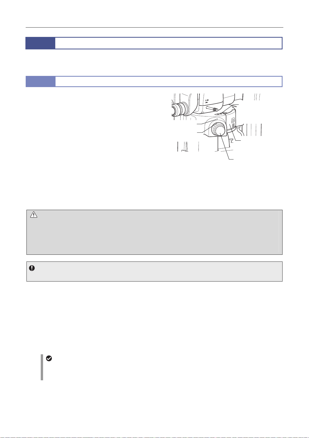
Chapter 4 Functions and Operations of the Devices
A
r
9
The microscope system can be used with the status detection model P2-EFLI Epi Fluorescence Attachment and Motorized
P2-EFLM Epi Fluorescence Attachment.
9.1
This illuminator is attached between the zooming body and tube.
HG precentered fiber illuminator is used as the light source. The
light coming from the light source is led into the device by the HG
fiber and then passed through the filter cube attached to the
internal turret for epi-fl illumination.
The turret can be attached with up to four filter cubes; the
addresses of the attachment positions are FL1 to FL4. For the
attachable filter cube types, those for fluorescence, bright-field,
and empty are available. Turn the filter cube switching knob to
assign to the indicator the turret address (FL1 to FL4) of the filter
cube to be placed into the optical path.
For systems where a control box has been connected, the
information about the turret address on the optical path is sent to
the control box via a motorized focus unit or relay box, and then
transmitted to the DS-L3 DS Camera Control Unit and personal
computer.
CAUTION
Do not use the epi-fluorescence attachment while the filter cube replacement cover is open. Harmful light including ultraviolet
light may leak and affect fluorescence observation.
Immediately after diascopic observation using an epi-fluorescence attachment, the front face of the empty cube may become
hot, resulting in burns. Do not touch the front face of the empty cube. Replace the empty cube several minutes after finishing
the diascopic observation.
Epi-Fluorescence Attachment
P2-EFLI Epi Fluorescence Attachment
Index mark
Turret address
indication
BINO
PHOTO
1
2
Filter cube indication
label
(label attachment
position)
Filter cube
replacement hole
cove
Filter cube
switching knob
P2-EFLI Epi Fluorescence Attachment
Be sure to attach four cubes to the turret.
Attach an empty cube to the position to which no filter cube is attached.
Filter cube
P2-EFL GFP-B, P2-EFL GFP-L, and P2-EFL RFP Filter Cubes: Used for fluorescence observation with a given
wavelength.
P2-EFLC Filter Cube: Used for fluorescence observation with an arbitrary wavelength when combined with arbitrary
filters, for example.
P2-EFLBF Filter Cube (Bright Field): Used for bright-field episcopic observation.
Empty cube (Three cubes are supplied with an epi-fluorescence attachment): Used when performing diascopic
illumination observation using the epi-fluorescence attachment.
Light shielding plate
The device is equipped with a light shielding plate for preventing the reflection of ultraviolet light. Use the light shielding
plate when performing fluorescence microscopy. When in use, the light shielding plate can be pushed aside to positions
up to 45° horizontally to the rear. When not in use, the plate can be pushed aside to positions up to 170°.
58
Page 73
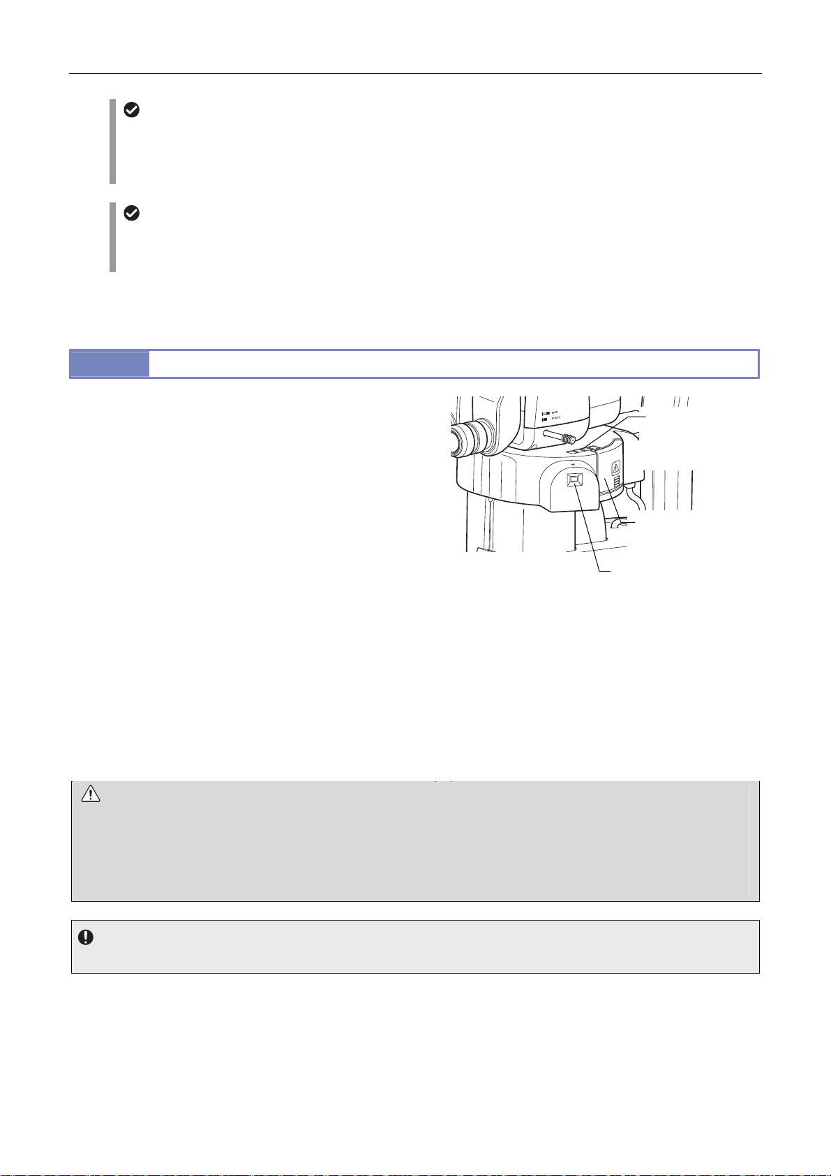
Chapter 4 Functions and Operations of the Devices
Bright-field episcopic observation
This is useful for observing the entire image of the opaque specimen during fluorescence observation. Although the
P2-EFLBF Filter Cube contains the UV blocking filter, adjust the brightness of the illuminator so that illumination is not too
bright. When observing light reflected from the specimen with a mirror-like surface, the brightness on the right path differs
from that on the left optical path. Also, duplicated images may be produced by internal half mirror.
OCC light shielding plate
When using an epi-fluorescence attachment with a diascopic illumination base, Nikon recommends closing the OCC light
shielding plate on the dia-illumination completely. This can decrease background noise caused by intrinsic fluorescence in
the diascopic illuminator.
For details about using the light source, refer to the instruction manual for the light source.
9.2
The motorized epi-fluorescence illuminator is attached between
the zooming body and tube. A HG precentered fiber illuminator is
used as the light source. The light coming from the light source is
led into the device by the HG fiber and then passed through the
P2-EFLM Motorized Epi Fluorescence Attachment
Filter cube indication
label
(label attachment
position)
filter cube attached to the internal turret for epi-fl illumination.
The turret can be attached with up to four filter cubes; the
addresses of the attachment positions are FL1 to FL4. For the
attachable filter cube types, those for fluorescence, bright-field,
and empty are available. On the remote control, press the filter
cube switching buttons (FL1 to FL4) to specify the turret address
of the filter cube to be placed into the optical path. The LED of the
pressed button lights so that the turret address on the optical path
P2-EFLM Motorized Epi Fluorescence Attachment
Filter cube
replacement hole
cover
Turret address check
window
can be identified. The attachment has a turret address check
window on the right front so that the turret address on the optical
path can be identified.
For systems where a control box has been connected, the
information about the turret address on the optical path is sent to
the control box via a motorized focus unit or relay box, and then
transmitted to the DS-L3 DS Camera Control Unit and personal
computer.
CAUTION
Do not use the epi-fluorescence attachment while the filter cube replacement cover is open. Harmful light including ultraviolet
light may leak and affect fluorescence observation.
Immediately after diascopic observation using an epi-fluorescence attachment, the front face of the empty cube may become
hot, resulting in burns. Do not touch the front face of the empty cube. Replace the empty cube several minutes after finishing
the diascopic observation.
Be sure to attach four cubes to the turret.
Attach an empty cube to the position to which no filter cube is attached.
59
Page 74

Chapter 4 Functions and Operations of the Devices
Filter cube
P2-EFL GFP-B, P2-EFL GFP-L, and P2-EFL RFP Filter Cubes: Used for fluorescence observation with a given
wavelength.
P2-EFLC Filter Cube: Used for fluorescence observation with an arbitrary wavelength when combined with arbitrary
filters, for example.
P2-EFLBF Filter Cube (Bright Field): Used for bright-field episcopic observation.
Empty cube (Three cubes are supplied with an epi-fluorescence attachment): Used when performing diascopic
illumination observation using the epi-fluorescence attachment.
For details about using the light source, refer to the instruction manual for the light source.
Light shielding plate
The device is equipped with a light shielding plate for preventing the reflection of ultraviolet light. Use the light shielding
plate when performing fluorescence microscopy. When in use, the light shielding plate can be pushed aside to positions
up to 45° horizontally to the rear. When not in use, the plate can be pushed aside to positions up to 170°.
Bright-field episcopic observation
This is useful for observing the entire image of the opaque specimen during fluorescence observation. Although the
P2-EFLBF Filter Cube contains the UV blocking filter, adjust the brightness of the illuminator so that illumination is not too
bright. When observing light reflected from the specimen with a mirror-like surface, the brightness on the right path differs
from that on the left optical path. Also, duplicated images may be produced by internal half mirror.
OCC light shielding plate
When using an epi-fluorescence attachment with a diascopic illumination base, Nikon recommends closing the OCC light
shielding plate on the dia-illumination completely. This can decrease background noise caused by intrinsic fluorescence in
the diascopic illuminator.
60
Page 75
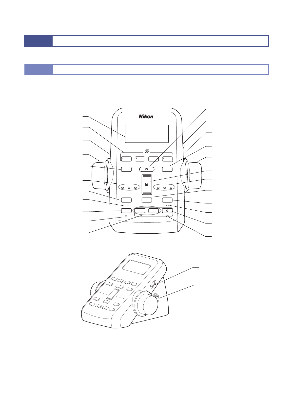
Chapter 4 Functions and Operations of the Devices
1 2 3 4
DISPLAY
BRIGHTNESS
ESCAPE
ALZ
LIMIT
ZOOM
STEP
Z-RESET
Z-SPEED
ZOOM STEP
Coarse
FL Cube
ON/OFF
ON/OFF
ON/OFF
ON/OFF
Fine
Ex Fine
0.5x
0.1x
r
r
g
r
10
A remote controller, foot switch, and photo release are available as remote control devices of the microscope system.
10.1
The P2-RC Remote Controller is used mainly for focus and zoom operations.
The remote controller is attached to the REMOTE connector of the P2-CTLA Control Box.
(6) Filter cube switching
(4) Fine/coarse focus
Remote Control Device
P2-RC Remote Controller
(1) LCD
button
switching button
(3) Focus knob
FL Cube
BRIGHTNESS
(9) Capture button
(2) Backlight control dial
(4) Fine/coarse focus
switchin
button
(8) Z-reset button
(3) Focus knob
(7) LCD display switching
(5) Focus speed indicato
(13) Escape button
(14) Escape ON/OFF
(17) ALZ button
(18) ALZ ON/OFF
(19) Diascopic LED
brightness control button
button
indicato
Coarse
DISPLAY
Z-SPEED
ESCAPE
ON/OFF
ALZ
ON/OFF
Fine
Ex Fine
−+
+
−
ZOOM
STEP
ZOOM STEP
1x1x0.5x
Z-RESET
LIMIT
ON/OFF
ON/OFF
(10) Zoom button
(12) Zoom step indicator
0.1x
(11) Zoom step switching
button
(15) Limit button
(16) Limit ON/OFF indicator
(20) Diascopic LED ON/OFF
button
(21) Diascopic LED ON/OFF
indicato
(2) Backlight control dial
(4) Fine/coarse focus
switching button
(on both sides)
Front Right Side
P2-RC Remote Controller
61
Page 76

Chapter 4 Functions and Operations of the Devices
Functions and indications of the operation buttons
No. Button/Indication Function/Description
(1) LCD This 4 x 16 LCD displays magnification, filter cube names, and other
information. (See “ LCD indications.”)
(2) Backlight control dial Adjusts the backlight of the LCD. When turned fully clockwise, the LCD’s
backlight and the LED’s are turned off.
(3) Focus knob Vertically moves the focus mount of the P2-MFU Motorized Focus Unit. Turn
backward to move upward. Turn forward to move downward.
(4) Fine/coarse focus switching button Switches the focus speed. Each time the button is pressed, the speed is
cyclically switched in order of coarse, fine, and extra fine.
(5) Focus speed indicator When the focus speed is changed, the corresponding indicator
(Coarse/Fine/ExFine) lights.
(6) Filter cube switching button Turns the turret of the motorized epi fluorescence attachment. The filter cube
of the address of the pressed button is brought into the optical path and the
LED of the corresponding button (address on the optical path) lights.
(7) LCD display switching button Switches the display on the LCD. Two pages can be switched for display. (See
“ LCD indications.”)
(8) Z-reset button Resets the indication of the Z position (focus position) on the LCD to 0.
Pressing at another position sets that position as 0.
(9) Capture button Captures images using a DS camera.
(10) Zoom button Changes the magnification of the zooming body. Pressing the upper button
causes the magnification to increase. Pressing the lower button causes the
magnification to decrease. Pressing and holding the button causes the
magnification to change continuously.
(11) Zoom step switching button Switches the zoom step size in order of 1x, 0.5x, and 0.1x.
(12) Zoom step indicator When the zoom step size is changed, the corresponding LED (1x, 0.5x, and
0.1x) lights.
(13) Escape button Moves the vertical movement part upward by the preset distance so that it
stays in position. The vertical movement is not possible in this escape status.
Pressing the Escape button again causes the vertical movement part to return
to the previous position. Pressing and holding the Escape button causes the
vertical movement part to exit escape.
The travel distance can be newly set or changed using the setup tool or
NIS-Elements.
(14) Escape ON/OFF indicator The LED lights when in escape status.
(15) Limit button When the limit button is pressed, the current position is set as the limit position
so that the vertical movement part does not move down passing the limit point.
Pressing the limit button again cancels the limit position setting.
(16) Limit ON/OFF indicator The LED lights when the limit position has been set.
(17) ALZ button Activates the ALZ function. To deactivate the ALZ function, press the button
again. For the ALZ function, see “ Useful zoom operation functions (ALZ
function)” in “1.2 SMZ25 Zooming Body” in this chapter.
(18) ALZ ON/OFF indicator The LED lights when the ALZ function is activated.
(19) Diascopic LED brightness control
button
(20) Diascopic LED ON/OFF button Turns diascopic LED illumination on and off.
(21) Diascopic LED ON/OFF indicator The LED lights when diascopic LED illumination is turned on.
Changes the brightness of the diascopic LED illumination. Press [+] to
increase the brightness and [-] to decrease the brightness.
62
Page 77
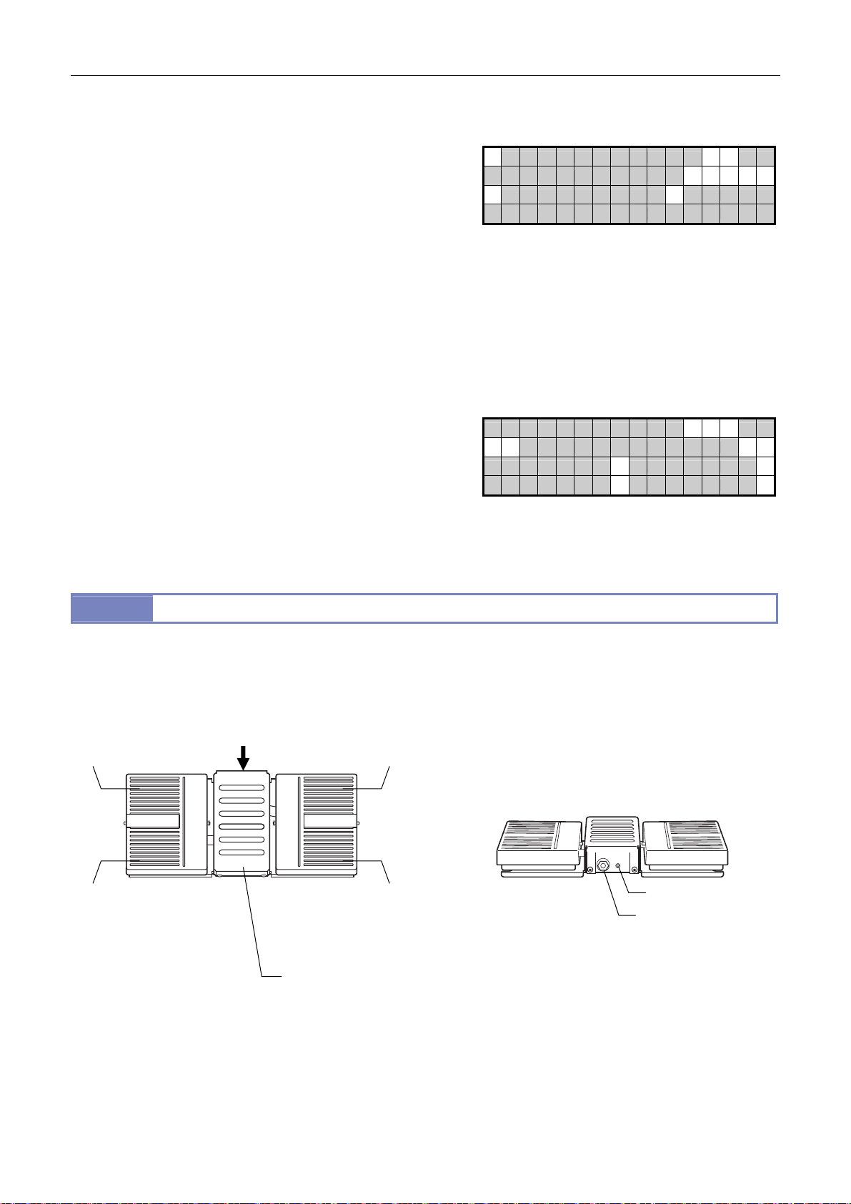
Chapter 4 Functions and Operations of the Devices
LCD indications
1st page
1: Total magnification (zoom magnification x objective
magnification x eyepiece magnification)
(Example) [MAG: 236.25x]
2: Zoom magnification
(Example) [ZOOM: 15.75x]
3: Objective magnification
(Example) [OBJ: 0.75x]
4: Eyepiece magnification
(Example) [EP10x]
5: Diascopic LED light intensity
(Example) [LEDDIA _______ ]
6: Field of view
] Stereoscopic view or [ ○] Vertical view
[
○○
2nd page
1: Actual field of view
(Example) [FOV: 24.44 mm]
2: P-PS32 Plain Stand Z-coordinate
(Example) [Z: 100.000 mm]
3-6: Filter cube name (all)
(Example) [1: GFP-B]
7: Field of view
[
] Stereoscopic view or [ ○] Vertical view
○○
10.2
AZ-FSW Foot Switch
The AZ-FSW Foot Switch is a controller that enables a pedal to be used for focus and zoom operations.
The foot switch is connected to the FOOT connector of the P2-CTLA Control Box. To use the foot switch, the P2-RC Remote
Controller must be connected to the P2-CTLA Control Box.
(1) Left rear of the foot pedal
(Motorized focus unit
Z-coordinate UP switch)
A
(2) Right rear of the foot pedal
(Motorized magnification UP
switch)
1 6
2
3 4
5
1 7
2
3 4
5 6
(1) Left front of the foot
pedal
(Motorized focus unit
Z-coordinate DOWN
switch)
(2) Right front of the
(3) Foot rest
foot pedal
(Motorized
magnification
DOWN switch)
AZ-FSW Foot Switch
63
Connector attachment section
(viewed from arrow A)
PHOTO CTRL
(4) CTRL connector
(5) PHOTO connector
Page 78

Chapter 4 Functions and Operations of the Devices
No. Operation Section Function
(1) Left foot pedal Left rear foot pedal (motorized focus unit Z-coordinate DOWN switch)
Drives the motorized focus unit downward.
When pressed, lowers the unit by 1.6 μm. Press and hold to move the unit continuously.
The speed changes based on the magnification and nosepiece address. (See the table
below.)
If a nosepiece address has not been set, the unit moves at the maximum speed.
Left front of the foot pedal (motorized focus unit Z-coordinate UP switch)
Drives the motorized focus unit upward.
When pressed, raises the unit by 1.6 μm. Press and hold to move the unit continuously.
The speed changes based on the magnification and nosepiece address. (See the table
below.)
If a nosepiece address has not been set, the unit moves at the maximum speed.
Coarse
Magnification
Nosepiece
address
SMZ25 0.63 to 5.0 5.1 to 10.0 10.1 to 15.75
SMZ18 0.75 to 4.0 4.1 to 8.0 8.1 to 13.5
1
2
10 (mm/second)
Fine
Magnification
Nosepiece
address
Magnification
Nosepiece
address
(2) Right foot pedal Right rear of the foot pedal (motorized magnification UP switch)
Increases the magnification by one step. The step size depends on the zoom step size
setting.
Press and hold to increase the magnification continuously.
The zoom step size depends on the setting of the zoom step switching button on the remote
controller.
Right front of the foot pedal (motorized magnification DOWN switch)
Decreases the magnification by one step. The step size depends on the zoom step size
setting.
Press and hold to decrease the magnification continuously.
The zoom step size depends on the setting of the zoom step switching button on the remote
controller.
SMZ25 0.63 to 5.0 5.1 to 10.0 10.1 to 15.75
SMZ18 0.75 to 4.0 4.1 to 8.0 8.1 to 13.5
1 5 (mm/second) 4 (mm/second) 2 (mm/second)
2 2 (mm/second) 1 (mm/second) 0.5 (mm/second)
Extra fine
SMZ25 0.63 to 5.0 5.1 to 10.0 10.1 to 15.75
SMZ18 0.75 to 4.0 4.1 to 8.0 8.1 to 13.5
1 0.5 (mm/second) 0.4 (mm/second) 0.2 (mm/second)
2 0.2 (mm/second) 0.1 (mm/second) 0.0.5 (mm/second)
(3) Foot rest Used as a foot rest.
(4) CTRL connector Attach to the FOOT connector of the P2-CTLA Control Box using the supplied cable.
(5) PHOTO connector Connect the AZ-PCR Photo Release. (See “10.3 AZ-PCR Photo Release” in this chapter.)
64
Page 79
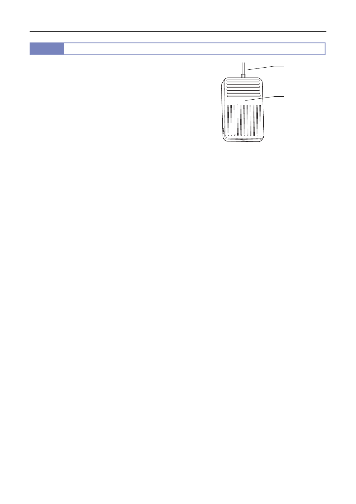
Chapter 4 Functions and Operations of the Devices
A
A
10.3
The AZ-PCR Photo Release is a foot switch for capturing images
using the camera connected to the microscope.
The photo release is connected to the PHOTO connector of the
Z-FSW Foot Switch.
For operations using a DS camera control unit such as the DS-L3
after a DS camera head has been attached to the microscope,
connect the DS camera control unit to the P2-CTLA Control Box
(USB connection). Next, connect the photo release to the
Z-FSW Foot Switch connected to the control box. The camera
can then capture images simply by stepping on the pedal of the
photo release.
AZ-PCR Photo Release
AZ-PCR Photo Release
Connection
cable
Foot switch
65
Page 80
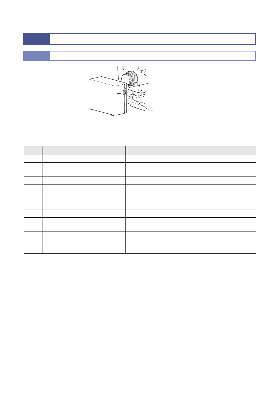
Chapter 4 Functions and Operations of the Devices
11
11.1
When electrically connected to the following devices, the P2-CTLB Control Box can detect the device states and handle
communications:
No. Device Operation
Control/Communications Device and Relay Device
P2-CTLB Control Box
Power LED
Power switch
P2-CTLB Control Box
(1) SMZ18 Zooming Body Detects the magnification.
(2) P2-DBL LED Diascopic Illumination Base Turns On/Off the LED illumination, controls the illumination, and
monitors the light intensity.
(3) P2-RLY Relay Box Relays communications.
(4) P2-EFLI Epi Fluorescence Attachment Detects the turret address on the optical path.
(5) P2-RNI2 Intelligent Nosepiece Detects the nosepiece address on the optical path.
(6) C-HGFIE HG Precentered Fiber Illuminator Switches the ND filter and opens/closes the shutter.
(7) C-HGFIE HG Precentered Fiber Illuminator Communications
(8-1) DS-L3 DS Camera Control Unit plus DS
camera
(8-2) Personal computer plus DS-U3 DS Camera
Control Unit plus DS camera
(9) AC adapter 24 V power input
Communications
Communications
The power supply for control provides power for the board in the control box and devices (1) to (5).
Devices (1), (4), and (5) are connected through device (3).
One type-B USB connector is equipped so that device (8-1) or (8-2) can be connected. Note that both devices cannot be
connected at the same time.
To operate using a personal computer after connecting device (8-1), connect the USB cable from the personal computer
to device (8-1).
Communications with device (7) are handled through a RS232C connection. Communications with device (8-1) or (8-2)
are handled through a USB connection.
66
Page 81
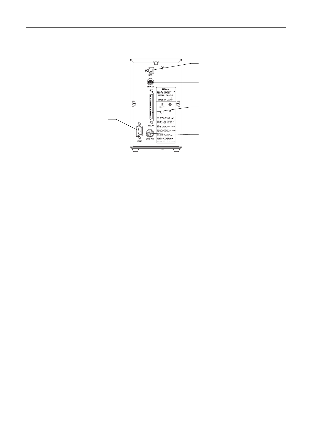
Chapter 4 Functions and Operations of the Devices
Connector names and connection destinations
The figure below shows the connectors on the rear of the control box and the connection destinations:
USB
(Connect to the USB port of a
personal computer or the DS-L3.)
LEDDIA
(Connect to the LED light control
terminal of the P2-DBL LED
Diascopic Illumination Base.)
RELAY
(Connect to the P2-RLY Relay Box
HGFIE
(Connect to the RS232C port of
the C-HGFIE HG Precentered
Fiber Illuminator.)
Rear of the P2-CTLB
For the power cable connected to the AC adapter, use the one specified in Chapter 8, “2 Performance Properties.”
or P2-RLYC Relay Cable.)
DC24V IN
(Connect to the 24 V AC adapter.)
67
Page 82
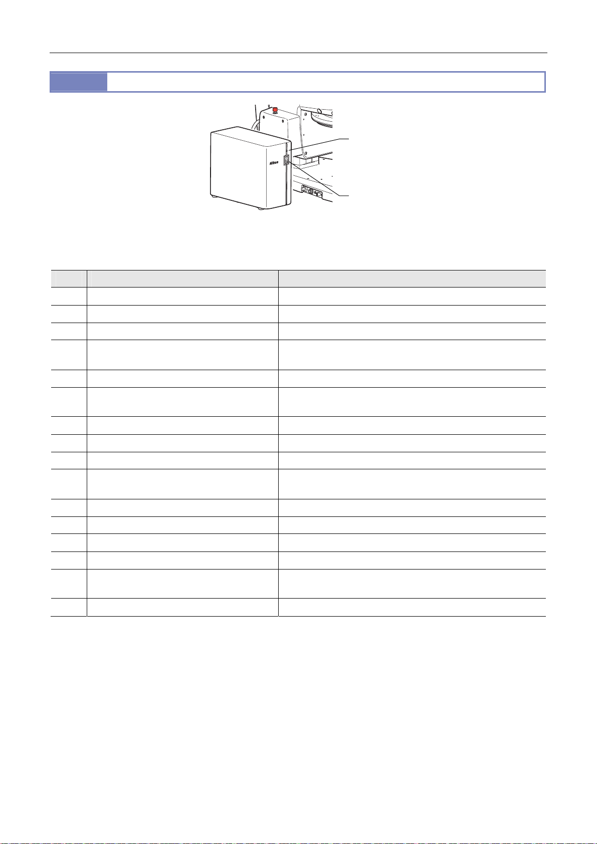
Chapter 4 Functions and Operations of the Devices
11.2
When electrically connected to the following devices, the P2-CTLA Control Box can perform motorized control of the devices,
detect the device states, and handle communications:
No. Device Operation
(1) SMZ25 Zooming body Motorized control of magnification
(2) SMZ18 Zooming body Detects the magnification.
(3) P2-MFU Motorized Focus Unit Motorized control of focus
P2-CTLA Control Box
Power LED
Power switch
P2-CTLA Control Box
(4) P2-DBL LED Diascopic Illumination Base Turns On/Off the LED illumination, controls the illumination, and
monitors the light intensity.
(5) P2-RLY Relay Box Relays communications.
(6) P2-EFLM Motorized Epi Fluorescence
Attachment
(7) P2-EFLI Epi Fluorescence Attachment Detects the turret address on the optical path.
(8) P2-RNI2 Intelligent Nosepiece Detects the nosepiece address on the optical path.
(9) P2-RC Remote Controller Communications
(10) AZ-FSW Foot Switch Detects the switch states, moves the P2-MFU Motorized Focus Unit
(11) AZ-PCR Photo Release Detects the switch states and captures images.
(12) C-HGFIE HG Precentered Fiber Illuminator Switches the ND filter and opens/closes the shutter.
(13) C-HGFIE HG Precentered Fiber Illuminator Communications
(14-1) DS-L3 DS Camera Control Unit plus DS camera Communications
(14-2) Personal computer plus DS-U3 DS Camera
Control Unit plus DS camera
(15) AC adapter 24 V power input
Motorized control of turret rotation
vertically, and adjust the magnification of the SMZ25 Zooming Body.
Communications
The power supply for control provides power for the board in the control box and devices (1) to (11).
Devices (1), (2), (6), (7), and (8) are connected through device (3) or (5).
One type-B USB connector is equipped so that device (14-1) or (14-2) can be connected. Note that both devices cannot
be connected at the same time.
To operate using a personal computer after connecting device (14-1), connect the USB cable from the personal computer
to device (14-1).
Communications with device (9) are handled through serial communications, communications with device (13) are
handled through a RS232C connection, and communications with device (14-1) or (14-2) are handled through a USB
connection.
68
Page 83
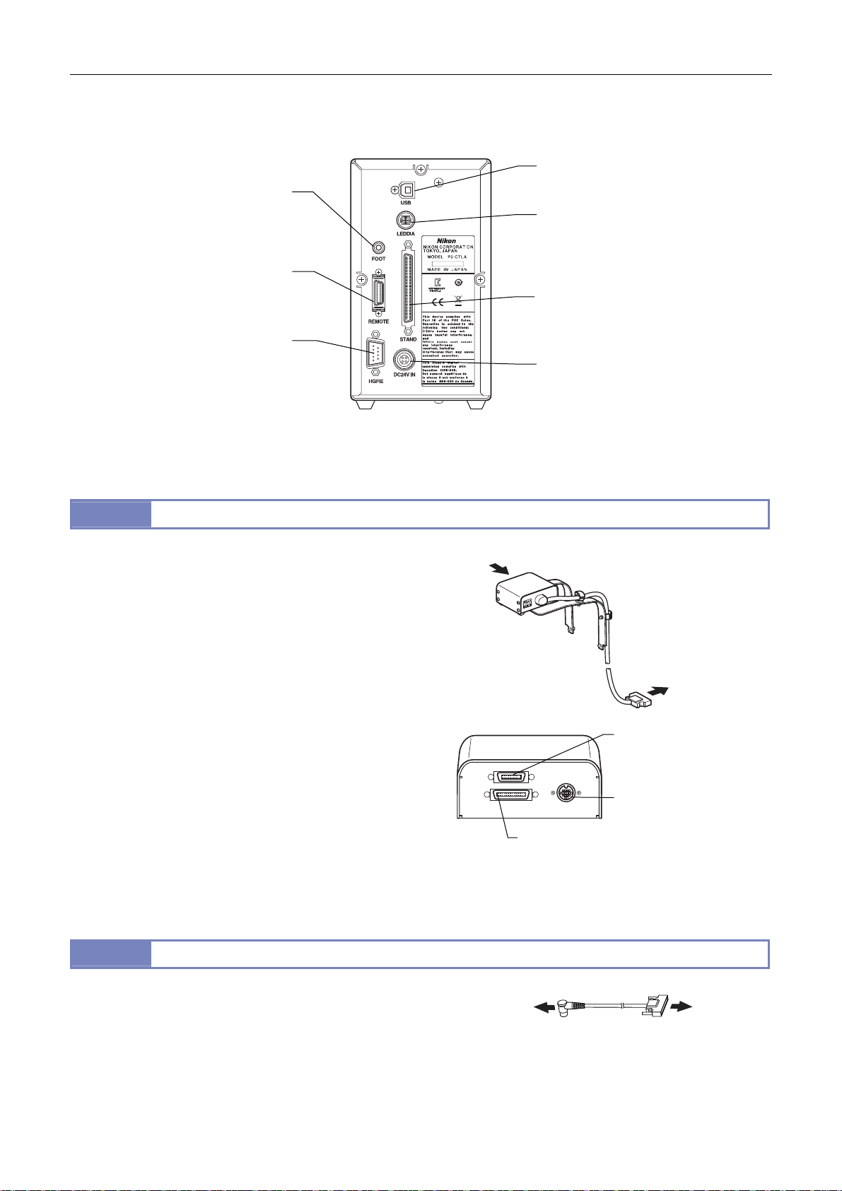
Chapter 4 Functions and Operations of the Devices
NP
ZOOM
FL
A
A
Connector names and connection destinations
The figure below shows the connectors on the rear of the control box and the connection destinations:
USB
FOOT
(Connect to the CTRL connector
of the AZ-FSW Foot Switch using
the cable supplied with the foot
switch.)
REMOTE
(Connect to the P2-RC Remote
Controller.)
HGFIE
(Connect to the RS232C port of
the C-HGFIE HG Precentered
Fiber Illuminator.)
Rear of the P2-CTLA
Use the power cable specified in Chapter 8, “2 Performance Properties.”
11.3
When electrically connected to the following devises, the P2-RLY
P2-RLY Relay Box
View
Relay Box can relay signals for motorized control of the devices
and detect the device states:
(1) P2-CTLA Control Box
(2) P2-CTLB Control Box
(3) SMZ25 Zooming Body
(4) SMZ18 Zooming Body
(5) P2-EFLM Motorized Epi Fluorescence Attachment
(6) P2-EFLI Epi Fluorescence Attachment
(7) P2-RNI2 Intelligent Nosepiece
The drive signals of devices (3) and (5) are relayed through
device (1) or (2). For devices (4), (6), and (7), address
information signals are relayed.
11.4
For systems where the P2-RLY Relay Box has not been
connected, the P2-RLYC Relay Cable is used to connect the
SMZ18 Zooming Body to the RELAY connector of the P2-CTLB
P2-RLYC Relay Cable
To the SMZ18
Zooming Body
Control Box. This enables the status detection signals to be
relayed.
Viewed from arrow A
(Connect to the USB port of a personal
computer or the DS-L3.)
LEDDIA
(Connect to the LED light control terminal
of the P2-DBL LED Diascopic Illumination
Base using the cable supplied with the
control box.)
STAND
(Connect to the P2-MFU Motorized
Focus Unit or the P2-RLY Relay Box.)
DC24V IN
(Connect to the 24 V AC adapter.)
ZOOM
(Connect to the SMZ25/SMZ18
Zooming Body.)
P2-RLY Relay Box
P2-RLYC Relay Cable
To the STAND connector
of P2-CTLA Control Box
or the RELAY connector
of P2-CTLB Control Box
FL
(Connect to the P2-EFLI/
P2-EFLM Epi Fluorescence
ttachment.)
NP
(Connect to the P2-RNI2
Intelligent Nosepiece.)
To the RELAY
connector of
P2-CTLB
Control Box
69
Page 84

Chapter 4 Functions and Operations of the Devices
☆☆☆
70
Page 85
Chapter
5
Assembling
This chapter contains the SMZ18/SMZ25 system configuration diagrams and lists of the system components, and explains
how to assemble the systems.
Before starting assembling, read the appropriate notes such as
product” at the beginning of this instruction manual and “3 Installation location” in “Notes on Handling the Product” in this
instruction manual.
CAUTION When moving or carrying the system
The SMZ18/SMZ25 system weighs over 20 kg in total.
When moving the assembled microscopy system, work with at least two people. Put hands in the depression at the front of the
base and the rear of both sides to lift up the system. Be very careful not to let fingers be caught when putting it down.
CAUTION “11 Cautions on assembling and installing the
Tools necessary for assembly
Tools Devices that supply tools
Hex wrench (nominal designation: 2.5) Intelligent nosepiece, P-SXY64 XY Stage
Hex wrench (nominal designation: 3) P-SXY64 XY Stage
Hex wrench (nominal designation: 4) Fiber holder
Hex wrench (nominal designation: 5) P-SXY64 XY Stage
Hex wrench (nominal designation: 6) Focus unit
Hex driver (nominal designation: 2) Focus unit, P-PS32 Plain Stand (fit-in type to the top of the support)
Hex driver (nominal designation: 4) Intelligent nosepiece, Focus mount adapter, Focus mount
Spanner wrench (nominal designation: 10) Fiber holder
71
Page 86
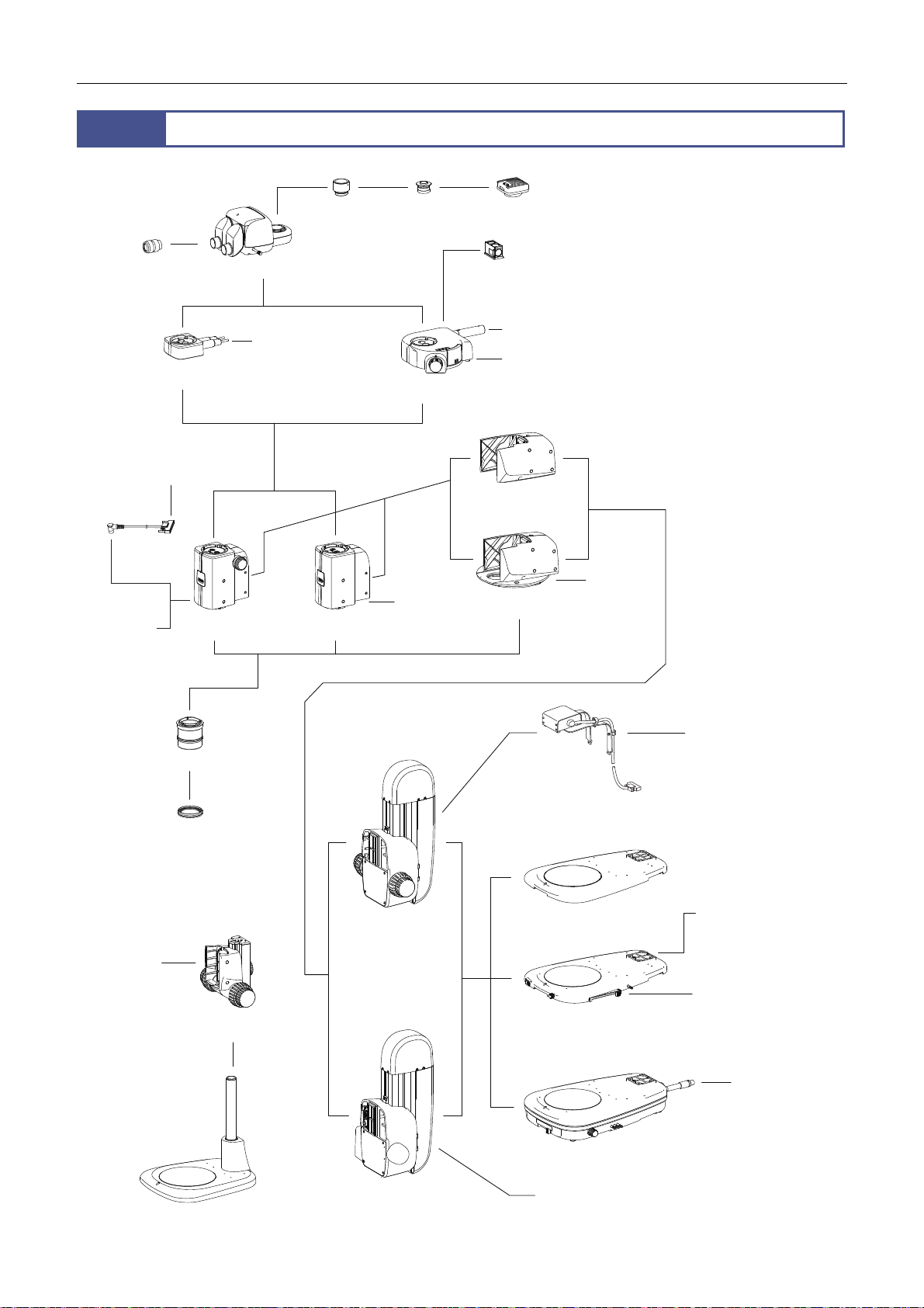
Chapter 5 Assembling
A
Signal cable
ZOOM*
1
Eyepiece Eyepiece tube
P2 RLYC
relay cable
System Configuration
P2-CI coaxial
epi illuminator
(With 1/4 lambda plate for
0.5x and 1x objectives)
P2-CTLB
control box
SMZ18
zooming body
TV tube
adapter
Fiber (C-FLED2 LED light
source for fiber illuminator)
SMZ25
zooming body
C-mount
adapter
Epi fluorescense
attachment
Signal cable
ZOOM*
DS camera
Filter cube
(P2-EFLBF is equipped with 1/4 lambda plate
for 0.5x and 1x objectives.)
(With light
shielding plate)
P2-FM focus mount
adapter
intelligent nosepiece
head
HG fiber (C-HGFI/C-HGFIE HG
precentered fiber illuminator )
Signal cable FL*
Signal cable
P2-RNI2
NP*
* Connected with FL, ZOOM
and NP on the P2-RLY relay
box or P2-MFU motorized
focus unit.
1/4 lambda
SMZ18
zooming
body
P-PS32 plain stand
Objective
plate
P2-FMDN
focus mount
P2-CTLA
or P2-CTLB control box
P2-RLY relay box
(Connectors: NP, ZOOM and FL)
P2-FU focus unit
P2-MFU
motorized focus unit
(Connectors: NP, ZOOM and FL)
P2-PB plain base
P2-DBL LED
diascopic illumination base
P2-DBF fiber diascopic
illumination base
P2-CTLA control box
P2-CTLA or P2-CTLB
control box
12V AC Adapter and
power cable
(Necessary when P2-CTL
or P2-CTLB control box is
not used.)
Fiber
(C-FLED2 LED light
source for fiber
illuminator)
72
Page 87
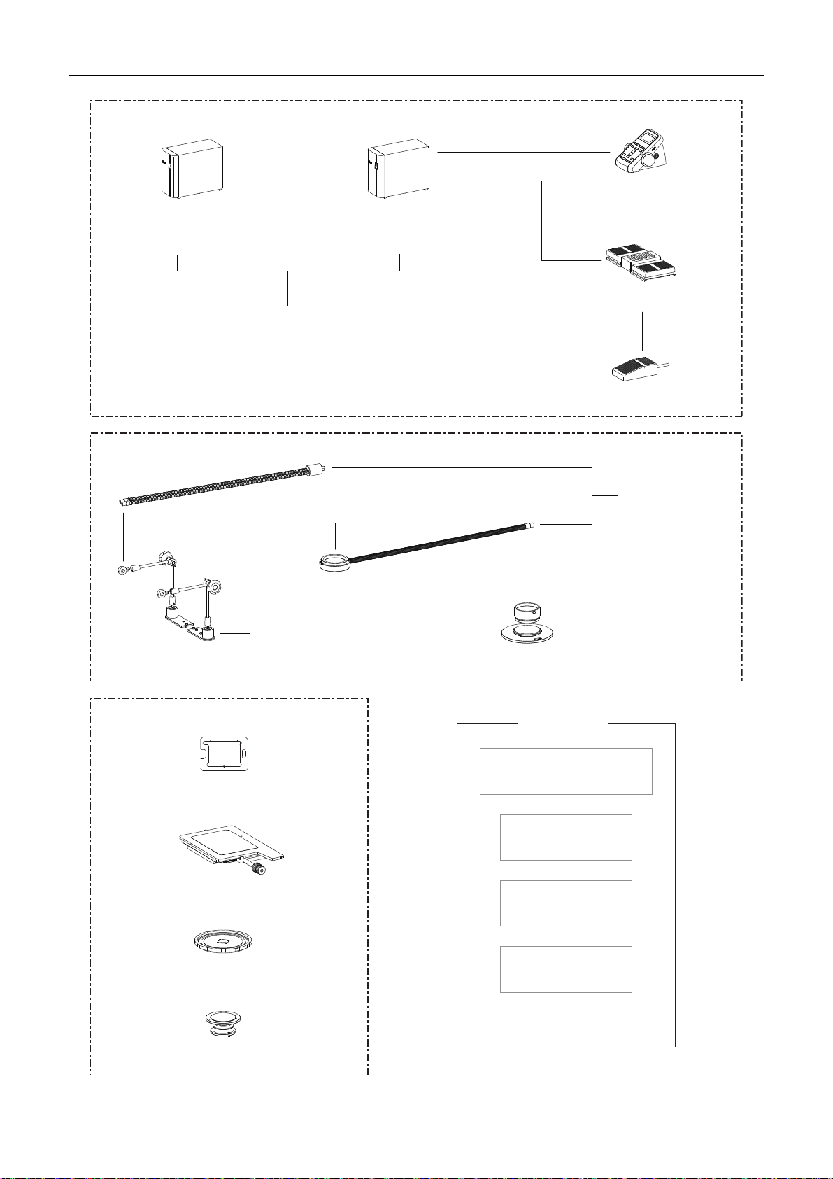
Chapter 5 Assembling
A
A
A
Control Box
P2-CTLB
control box
(Connectors: HGFIE, USB, LEDDIA,
RELAY, and DC24V IN)
24V AC Adapter and
power cable
P2-CTLA
control box
(Connectors: FOOT, REMOTE, HGFIE,
USB, LEDDIA, STAND, and DC24V IN)
Other Illuminators
P2-RC
remote controller
AZ-FSW
foot switch
AZ-PCR
photo release
C-FDF
flexible double arm fiber
illumination unit
ttached to base or stand
C-FIDH
fiber holder
Other Stages (Attached to base or stand)
Stage adapters
P-SXY64 XY stage
for AZ
ttached to 0.5x
or 1x objective
P2-FIR
ring fiber illumination unit
P2-POL
simple polarizing
attachment
Other Devices
P-DF LED dark field unit
(Optional P-DF-LSP light shielding
plate is available.)
ring illumination unit
C-HGFI/C-HGFIE
HG precentered
or 1x objective
Polarizer unit: Attached to base
or stand
P2-FIRL LED
fiber illuminator
C-FLED2 LED
light source for
fiber illuminator
nalyzer unit: Attached to 0.5x
C-SSL DIA
sliding stage
C-TRS
tilting stage
For details, refer to the instruction
manual for other devices.
C-FLED2
LED light source
for fiber illuminator
73
Page 88

Chapter 5 Assembling
2
Device List
Microscopy system is configured by devices that are marked with “.” For details about the restrictions regarding the
configurations, see Chapter 4, “Functions and Operations of the Devices.”
Device Model Name Device Name
Main Body
Focus Unit or
Focus Mount
Focus Mount
Adapter or
Nosepiece
Objective
Base, Stand, Stage
Tube
Eyepiece
Episcopic
Illuminator
Diascopic
Illuminator
Epi Fluorescence
Attachment
Control/Relay
Device
Remote Control
Device
SMZ18 Zooming Body
SMZ25 Zooming Body -
P2-MFU Motorized Focus Unit
P2-FU Focus Unit
P2-FMDN Focus Mount - -
P2-FM Focus Mount Adapter
P2-RNI2 Intelligent Nosepiece
P2-SHR Plan
Apo 0.5X
P2-SHR Plan
Apo 1X
P2-SHR Plan
Apo 1.6X
P2-SHR Plan
Apo 2X
P2-PB Plain Base
P2-DBL LED Diascopic Illumination
P2-DBF Fiber Diascopic Illumination
P-PS32 Plain Stand - - With an acrylic stage plate
P-SXY64 XY Stage
C-SSL DIA Sliding Stage
P2-TERG 100 Trinocular Tilting Tube
P2-TERG 50 Trinocular Tilting Tube
P2-TL100 Trinocular Tube L
C-W 10XB Eyepiece
C-W 15X Eyepiece
C-W 20X Eyepiece
C-W 30X Eyepiece
P2-CI Coaxial Epi Illuminator
C-FDF Flexible Double Arm Fiber
P2-FIR Ring Fiber Illumination Unit
P2-POL Simple Polarizing Attachment
P2-EFLM Motorized Epi Fluorescence
P2-EFLI Epi Fluorescence Attachment Optional
P2-CTLA Control Box
P2-CTLB Control Box Optional
P2-RLY Relay Box -
P2-RLYC Relay Cable Optional Optional Optional
P2-RC Remote Controller
AZ-FSW Foot Switch
AZ-PCR Photo Release
Objective
Objective
Objective
Objective
Base
Base
Illumination Unit
Attachment
Microscopy
System
under
Episcopic
Illumination
-
-
Optional Optional Optional
Optional
- Optional -
-
Optional Optional
Microscopy
System under
Diascopic
Illumination
and Epi-
fluorescence
Illumination
-
- Optional
Compact
System
Remarks
With an acrylic stage plate
With a transparent glass stage
-
plate
With a transparent glass stage
plate
With a 1/4 lambda plate
Retained by a C-FIDH Fiber
Holder
With a light shielding plate
Maximum of four filter cubes
can be attached.
-
-
Other devices: The P2-FIRL LED Ring Illumination Unit, P-DF LED Dark Field Unit, C-TRS Tilting Stage and DS cameras are available.
74
Page 89
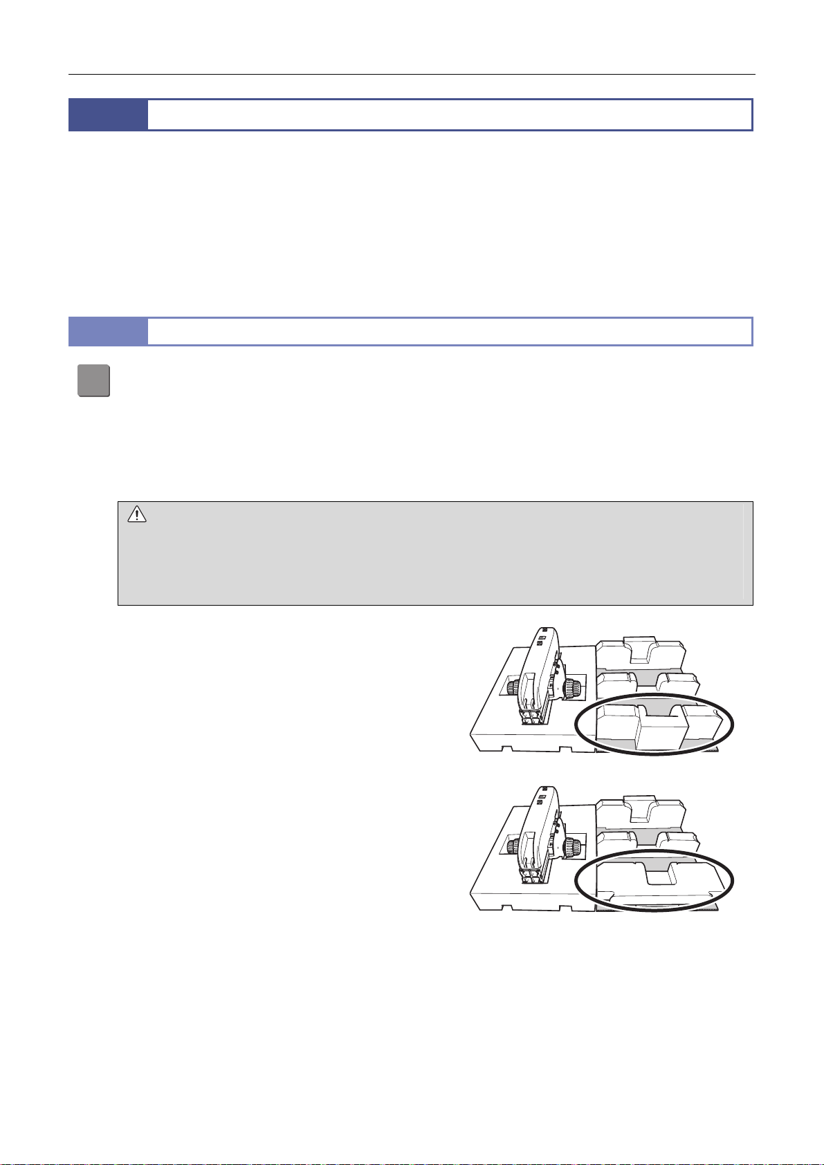
Chapter 5 Assembling
A
MADE IN CHINA
MADE IN CHINA
3
Assembly Procedures
The SMZ18 and SMZ25 stereo microscopes are system microscopes that can be configured in a variety of ways.
This chapter describes how to assemble the following three systems.
Episcopic illumination system (called the “EPI System” in this chapter)
Diascopic illumination + epi-fluorescence microscopy system (called the “DIA + EPI-FL System” in this chapter)
Compact system
This chapter also describes how to assemble the devices that can be added to the basic configuration of each system.
Refer to the preceding section “5.2 Device List” and check the devices to be used before assembling.
3.1
Assembling the EPI System and DIA + EPI-FL System
Attach the base.
1
ttach the base to be used to the P2-FU Focus Unit or P2-MFU Motorized Focus Unit.
The base is attached to the focus unit in the same manner in either case.
When configuring the DIA + EPI-FL System, select the dia-illumination base.
The following figure shows an example of attaching the P2-DBL LED Diascopic Illumination Base to the P2-FU
Focus Unit.
CAUTION Heavy Object
The base and focus unit are heavy. The focus unit is especially heavy so be very careful not to drop it when unpacking
or installing. Working with two or more people is recommended.
P2-FU Focus Unit: Approx. 11 kg
P2-MFU Motorized Focus Unit: Approx. 12 kg
(1) Remove the inner cover (cardboard) holding the
focus unit from the packing box. This inner cover is
used when connecting the focus unit and base.
Turn the inner cover over and place it on the desk
where the microscope is to be installed. Select a
desk and location free from vibration. Remove one
of the white polystyrene pieces holding the product
at either side, change its orientation as shown in the
figure and place it again.
P2-FU
MADE IN CHINA
P2-FU
MADE IN CHINA
Changing the orientation of the polystyrene piece
75
Page 90
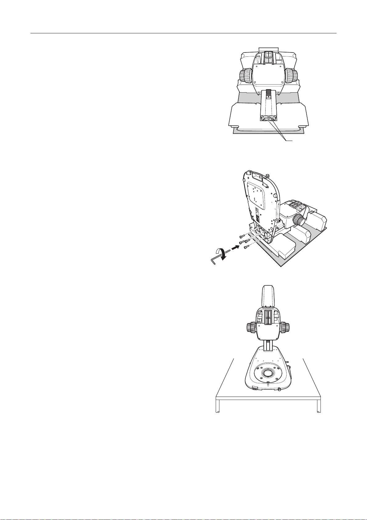
Chapter 5 Assembling
A
(2) Place the focus unit in the recession of the
polystyrene piece as show in the figure.
(3) Hold the base with the two base side positioning
holes aligned with the two positioning pins on the
focus unit, screw the four M8 hexagon socket head
bolts (supplied with the focus mount) from the
bottom of the base and tighten firmly using a hex
wrench (nominal designation: 6).
Positioning
pins
Fitting the focus unit
Attaching the base by tightening the bolts
(4) Install the attached device on the desk.
Attaching the stage plate
ttach the stage plate.
Depending on the type of the base, either a transparent glass stage plate or an acrylic stage plate is supplied.
The acrylic plate is black on one side and milky white on the other side. Attach the stage plate with the appropriate
side facing up based on the sample to be viewed.
Installing the base
76
Page 91
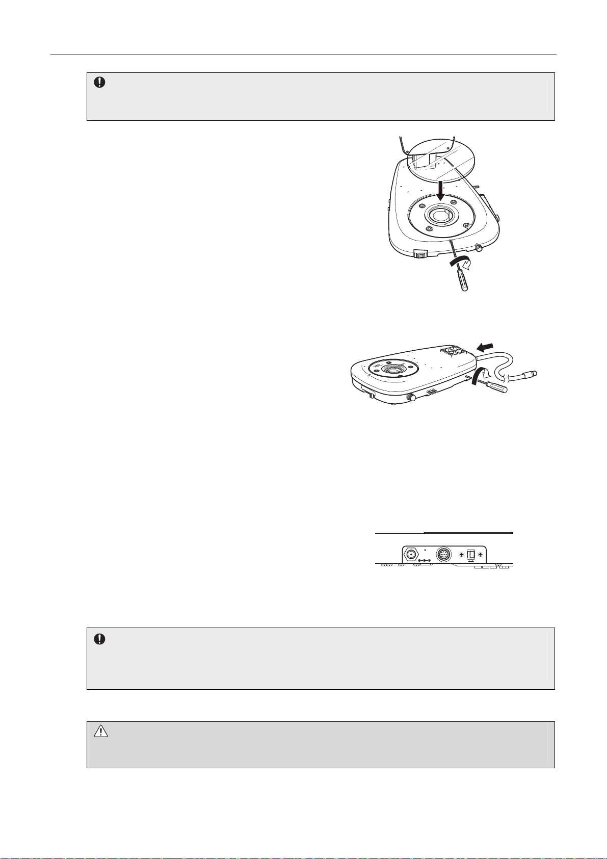
Chapter 5 Assembling
Glass stage plate handling precautions
Be very careful when handling the glass stage plate. Before attaching the glass stage plate, attach all other
components in order to avoid the risk of breaking the glass during assembly.
(1) Loosen the M4 set screw for the stage plate in the
front center of the base using a hex driver (nominal
designation: 2).
(2) Tilt the stage plate, fit it into the base, and then
tighten the fixing screw.
Attaching the stage plate by tightening the screw
Attaching a fiber to the P2-DBF Fiber Diascopic Illumination Base
When using the P2-DBF Fiber Diascopic Illumination
Base, connect the fiber to the base.
Insert a hex driver (nominal designation: 2) in the fiber
fixing screw hole at the right rear side of the base and
loosen the internal fixing screw (M4 set screw). Insert the
fiber to the rear side of the base until it reaches the limit
Attaching the fiber by tightening the screw
and tighten the fixing screw.
Firmly insert the other end of the fiber into the fiber
attachment hole of the C-FLED2 LED Light Source for
Fiber Illuminator. See the instruction manual for the light
source for details.
Connecting a cable to the P2-DBL LED Diascopic Illumination Base
Connect the cable to the connector on the left.
Connect the LED brightness control terminal “CTRL” with
the connector “LEDDIA” on the control box using the
CTRL cable supplied with the control box.
Connecting the LED dia-illumination
Connect the 12 V AC adapter to the AC adapter input
terminal that is used for the dia-illumination power supply
for the system without a control box connected.
Beware of overhang of cables
When these cables are connected, the connectors (cables) overhang to the left of the base. Be careful so that they do
not interfere with other devices such as a control box or they are not accidentally touched and disconnected while
attaching devices or performing observation.
Use the power cord specified in Chapter 8, “2 Performance Properties.”
WARNING Before connecting the power cord
To prevent electric shock, be sure to turn off the power switch (press it to the “” position) at the front of the base before
connecting the power cord to the adapter.
INPUT
12VDC ,
3.5A
CTRL
CTRL
ON OFF
base using a cable
77
Page 92
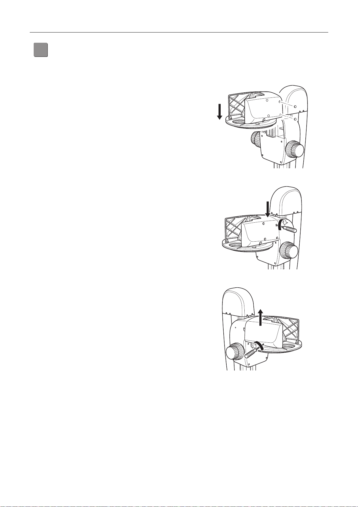
Chapter 5 Assembling
A
Attach the intelligent nosepiece or focus mount adapter.
2
ttach the intelligent nosepiece or focus mount adapter to the focus unit.
Both the intelligent nosepiece and focus mount adapter are attached to the focus unit in the same manner.
The following figure shows an example of attaching the intelligent nosepiece to the P2-FU Focus Unit.
(1) Remove the two rubber caps from the fixing bolt
holes at the right rear of the intelligent nosepiece (as
viewed from the front). Insert the hex driver (nominal
designation: 4) and completely loosen the two
internal M5 hexagon socket head bolts.
(2) Drop and fit the dovetail groove on the rear side of
the intelligent nosepiece onto the dovetail of the
focus unit mount from the top.
Attaching the intelligent nosepiece
(3) Firmly tighten the two fixing bolts using a hex driver
(nominal designation: 4). After tightening the bolts,
put the rubber caps back onto the bolt holes.
(4) The cover on the left side (as viewed from the front)
of the intelligent nosepiece is a sliding cover.
Removing this cover at this point will facilitate the
cable connection and routing in “[4] Connect the
signal cables.”
Remove the rubber caps from the two fixing bolt
holes at the bottom of the cover, loosen and remove
the two internal M5 hexagon socket head bolts using
a hex driver (nominal designation: 4), and pull the
cover up to remove it.
Firmly tightening the bolts
78
Page 93
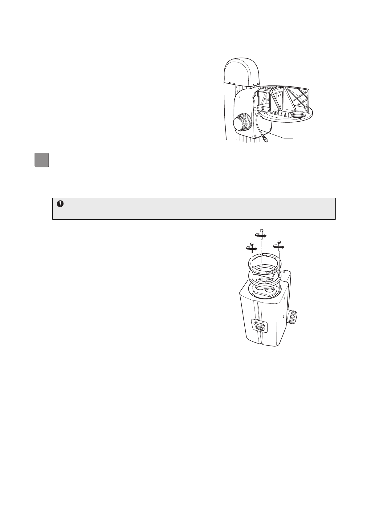
Chapter 5 Assembling
A
Connecting signal cables
Connect the signal cable of the intelligent nosepiece to the
connector “NP” on the motorized focus unit or the relay
box. (See “[4] Connect the signal cables.”)
Attach the zooming body.
3
ttach the SMZ18 or SMZ25 Zooming Body to the intelligent nosepiece or focus mount adapter.
Both zooming bodies are attached to the intelligent nosepiece or focus mount adapter in the same manner.
The following figure shows an example of attaching the SMZ18 Zooming Body to the intelligent nosepiece.
When attaching to the focus mount adapter
Step (1) is not necessary when attaching the zooming body to the focus mount adapter. Proceed to Step (2).
(1) Detach the objective attachment adapter (dovetail
and ring) attached under the zooming body. Loosen
the three M3 hexagon socket head bolts using a hex
wrench (nominal designation: 2.5).
Signal cable
(2) Completely loosen the two M5 hexagon socket head
bolts for fixing the zoom body on the right side of the
zooming body (as viewed from the front) using a hex
driver (nominal designation: 4).
(3) Drop and fit the dovetail groove on the rear side of
the zooming body onto the dovetail of the intelligent
nosepiece mount.
0.75
Detaching the objective attachment adapter
.
1
79
Page 94
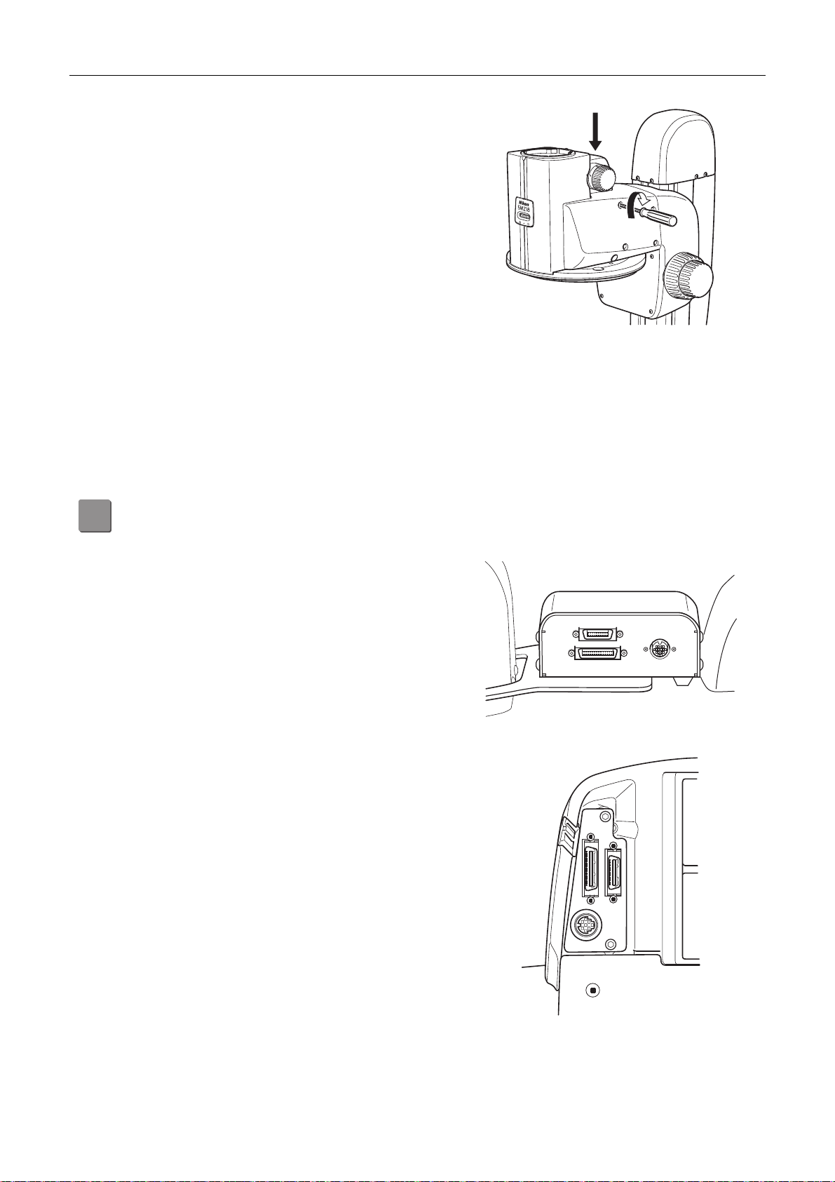
Chapter 5 Assembling
r
(4) Remove the two rubber caps from the fixing bolt
holes on the right front side of the intelligent
nosepiece (as viewed from the front). Insert a hex
driver (nominal designation: 4) into the holes and
firmly tighten the two zooming body fixing bolts. Afte
tightening the bolts, put the rubber caps back onto
the bolt holes.
Connecting signal cables
The signal cable for the SMZ25 comes from the left side of the zooming body. In case of the SMZ18, connect the
signal cable supplied with the SMZ18 to the round connector on the left side of the zooming body.
Connect the other end of the cable to the connector “ZOOM” on the motorized focus unit or relay box. (See “[4]
Connect the signal cables.”)
Attaching the zooming body
by tightening the bolts
Connect the signal cables.
4
Connect the cables necessary to detect the device state or to drive the motorized devices.
(1) Connect the signal cables.
The relay box has connectors “NP”, “ZOOM”, and
“FL” on the left side (as viewed from the front).
The P2-MFU Motorized Focus Unit has connectors
“NP”, “ZOOM” and “FL” on the left side of the unit
mount (as viewed from the front).
FL
ZOOM
The following cables are connected to each
connector.
Connectors on the relay box
NP: Connect the signal cable coming from the
intelligent nosepiece (there is no connection to
the NP connector if the focus mount adapter is
attached).
ZOOM: In case of the SMZ18 Zooming Body,
connect to the round connector on the left side of
ZOOM
FL
the zooming body using the signal cable supplied
with the SMZ18. In case of the SMZ25, connect
the signal cable coming from the left side of the
zooming body.
NP
FL: Connect the signal cable coming from the
P2-EFLM Motorized Epi Fluorescence
Attachment.
NP
Connectors on the motorized focus unit
80
Page 95
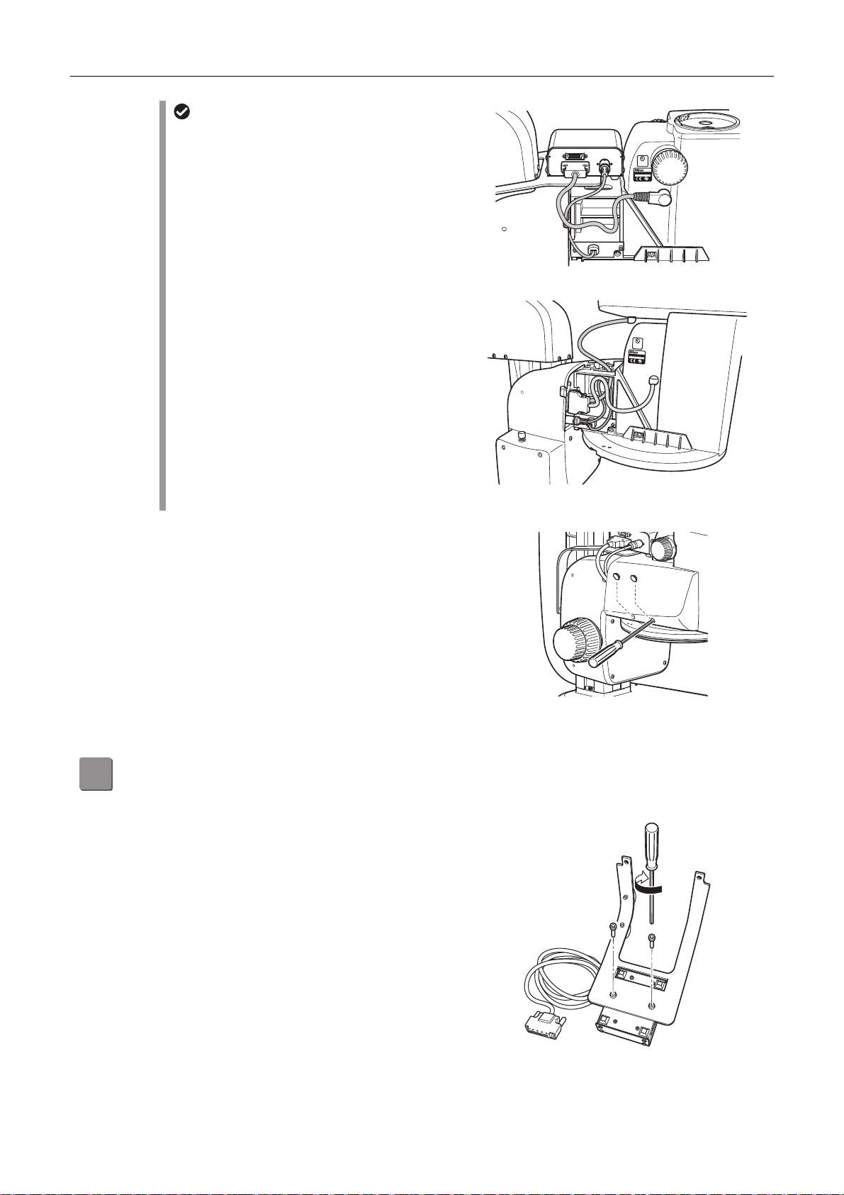
Chapter 5 Assembling
f
f
A
Cable routing
Route the cables before attaching the cover.
(In the figure, even though the relay box is already
attached for explanatory reasons, the attachment o
the relay box is explained in Step [5])
Bring out the cable from the SMZ zooming body
along the notch on the focus unit cover and connect
to the connector “ZOOM.” Pass the cable from the
intelligent nosepiece through the oval hole on top o
the mount, bring it out along the notch on the top of
the left side cover, and then connect to the
connector “NP.”
When the cable was connected to the motorized
focus unit, route the cable as shown in the figure.
Pass the cable from the motorized epi fluorescence
attachment through the oval hole at the top of the
mount, drop it down, and then connect to the
connector “FL.”
Cable connection to the motorized focus unit
(2) Attach the left cover of the intelligent nosepiece.
Route the cable and replace the intelligent
nosepiece left side cover removed in Step [2]-(4).
Align and fit the two protrusions on the left side
cover to the two notches in the top center of the
intelligent nosepiece, insert the two M5 hexagon
socket head fixing bolts in the fixing bolt holes at the
bottom of the cover and firmly tighten them using a
hex driver (nominal designation: 4). After the
attachment, cover the bolt holes using the rubber
caps.
2
FL
ZOOM
CUS
LISTED
4N75
INSPECTION
EQUIPMENT
MADE IN JAPAN
SMZ25
NP
Cable connection to the relay box
CUS
LISTED
4N75
INSPECTION
EQUIPMENT
SMZ25
MADE IN JAPAN
Attach the relay box. (P2-FU Focus Unit system only)
5
ttach the relay box to the P2-FU Focus Unit.
(1) The relay box is provided with the box itself with the
attaching arm removed. Assemble the box and arm
before attaching.
The orientation of the joint is such that the signal
cables come out from the right side (as viewed from
the front) with the relay box attached to the focus
unit. Align the box with the two attachment arm
screw holes and attach it by tightening the M5
hexagon socket head bolts supplied with the relay
box using a hex driver (nominal designation: 4).
Assembling the relay box
81
Page 96
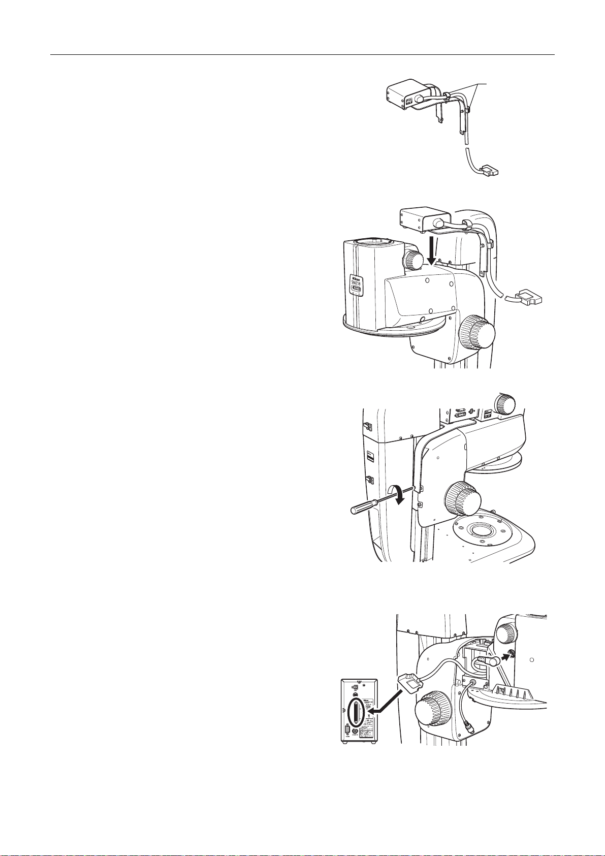
Chapter 5 Assembling
MA
D
E
I
N
C
HI
N
A
(2) Clamp the relay box cable using the arm clamps.
(3) Place the relay box arms over the focus unit as
shown in the figure, align the screw holes of the arm
with the two screw holes at the back of the focus
unit, and attach it by tightening the M5 hexagon
socket head bolts supplied with the relay box using a
hex driver (nominal designation: 4).
Clamps
Clamping a cable
Attaching the relay box
2
1
5
.7
0
8
Z1
SM
L
F
AN
JAP
N
I
DE
A
M
P
N
M
O
O
Z
MA
P
2
-FU
D
E
I
N
C
HI
N
A
Tightening the bolts for the relay box
Connecting the relay cable (when not using a relay box)
Use the P2-RLYC Relay Cable to output the zoom
magnification information of the SMZ18 to the P2-CTLB
Control Box without using a relay box.
5
7
.
0
1
2
Connect the relay cable to the round connector on the left
side of the SMZ18, route the wire along the notch of the
focus unit cover and connect to the RELAY connector of
the P2-CTLB Control Box.
Connecting the relay cable
82
Page 97
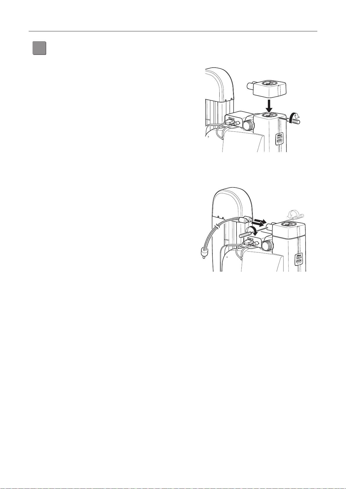
Chapter 5 Assembling
A
Attach the coaxial epi illuminator. (for the EPI System)
6
Attaching the fiber
ttach the coaxial epi illuminator to the zooming body.
(1) Completely loosen the M4 set screw for the
illuminator at the top front of the zooming body using
a hex driver (nominal designation: 2).
(2) Align and fit the round dovetail at the bottom of the
coaxial epi illuminator with the round dovetail of the
zooming body and tighten the fixing screw.
Loosen the M4 set screws for the fiber on the side of the
two fiber attachment holes on the rear side of the coaxial
epi illuminator using a hex driver (nominal designation: 2).
Insert the fiber to the attachment hole until it reaches the
limit and tighten the fixing screw.
Firmly insert the other end of the fiber into the fiber
attachment hole of the C-FLED2 LED Light Source for
Fiber Illuminator. See the instruction manual for the light
source for details.
Attaching the coaxial epi illuminator
by tightening the screw
Attaching the LED fiber by tightening the screw
Attaching the 1/4 lambda-plate
Screw and attach the 1/4 lambda plate supplied with the coaxial epi illuminator to the end of the objective.
In case of using a 0.5x objective, remove the protection ring at the end of the objective, and in case of using a 1x
objective, remove the correction glass at the end of the objective before attaching the 1/4 lambda plate.
83
Page 98
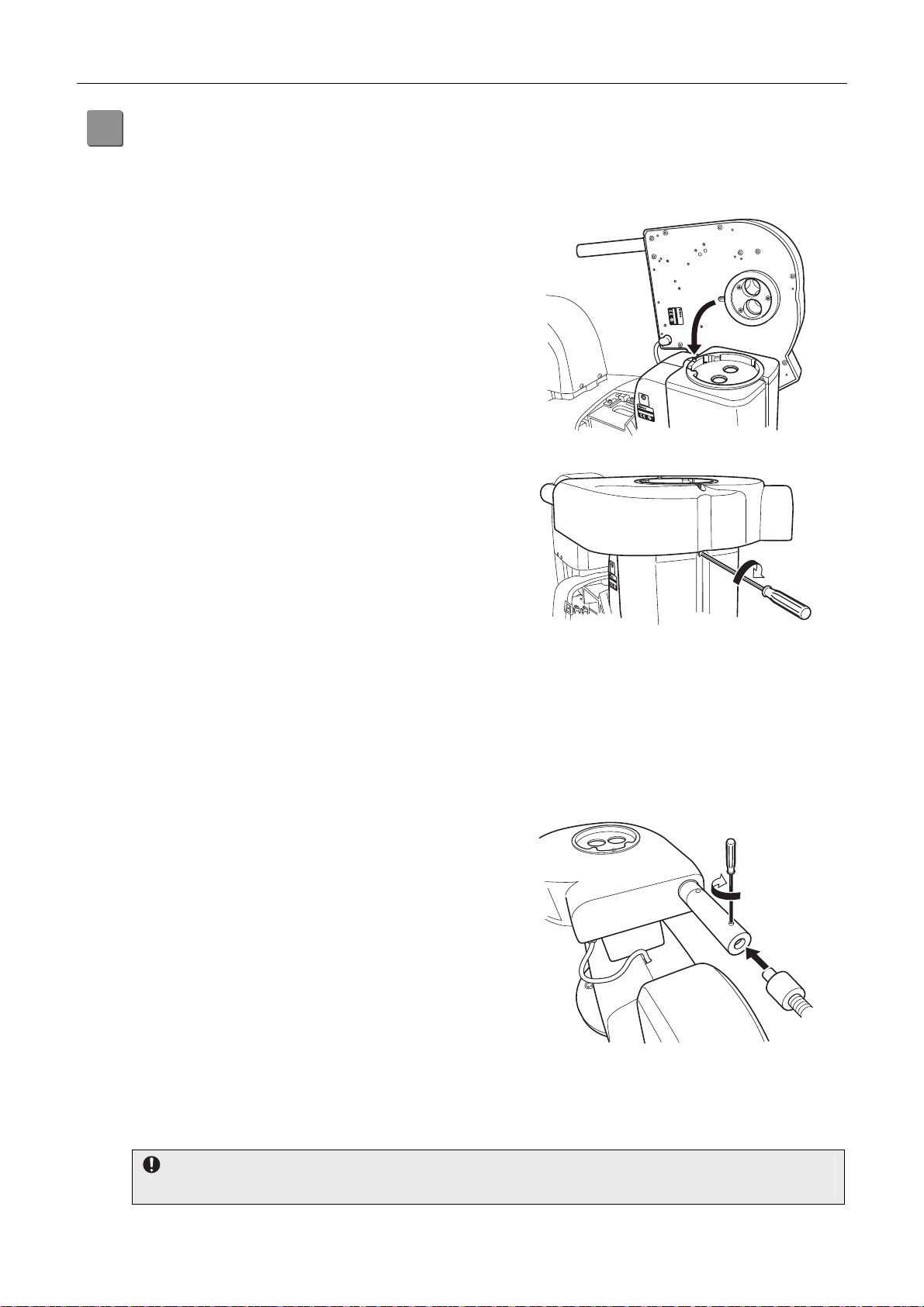
Chapter 5 Assembling
A
A
Attach the epi fluorescence attachment. (for the DIA + EPI-FL System)
7
ttach the P2-EFLM Motorized Epi Fluorescence Attachment or the P2-EFLI Epi Fluorescence Attachment to the
zooming body.
Both epi fluorescence attachments are attached to the zooming body in the same manner.
(1) Completely loosen the M4 set screw for the
illuminator at the top front of the zooming body using
a hex driver (nominal designation: 2).
(2) Align and fit the positioning groove at the far end of
the round dovetail at the bottom of the epi
fluorescence attachment with the positioning pin at
the far end of the round dovetail groove on top of the
zooming body, and then tighten the fixing screw.
MADE IN JAPAN
P2-EFLM
CUS
LISTED
4N75
INSPECTION
EQUIPMENT
MADE IN JAPAN
SMZ25
Attaching the epi fluorescence attachment
Tightening the screw for epi fluorescence
Connecting signal cables
Connect the signal cable that comes from the bottom of the epi fluorescence attachment to the connector “FL” on
the motorized focus unit or relay box. In case of the motorized unit, connect it inside the left cover of the intelligent
nosepiece. (See “[4] Connect the signal cables.”)
Attaching the HG fiber
Loosen the M4 set screw for the HG fiber on the top of the
HG fiber attachment hole on the rear side of the epi
fluorescence attachment using a hex driver (nominal
designation: 2).
Insert the emission side tip of the HG fiber to the
attachment hole until it reaches the limit and tighten the
fixing screw.
Firmly insert the source side connector to the HG fiber
attachment hole of the C-HGFI or C-HGFIE HG
Precentered Fiber Illuminator. See the instruction manual
for the light source for details.
Attaching the HG fiber by tightening the screw
Attaching the fluorescent filter cube
ttach the filter cube to the turret in the epi fluorescence attachment. Up to four filter cubes can be attached.
Do not touch the surface of the filter with bare hands
Scratches or fingerprints on the filter surface will degrade microscope images. Handle the filter cube carefully.
CUS
LISTED
4N75
INSPECTION
EQUIPMENT
SMZ25
MADE IN JAPAN
attachment
84
Page 99
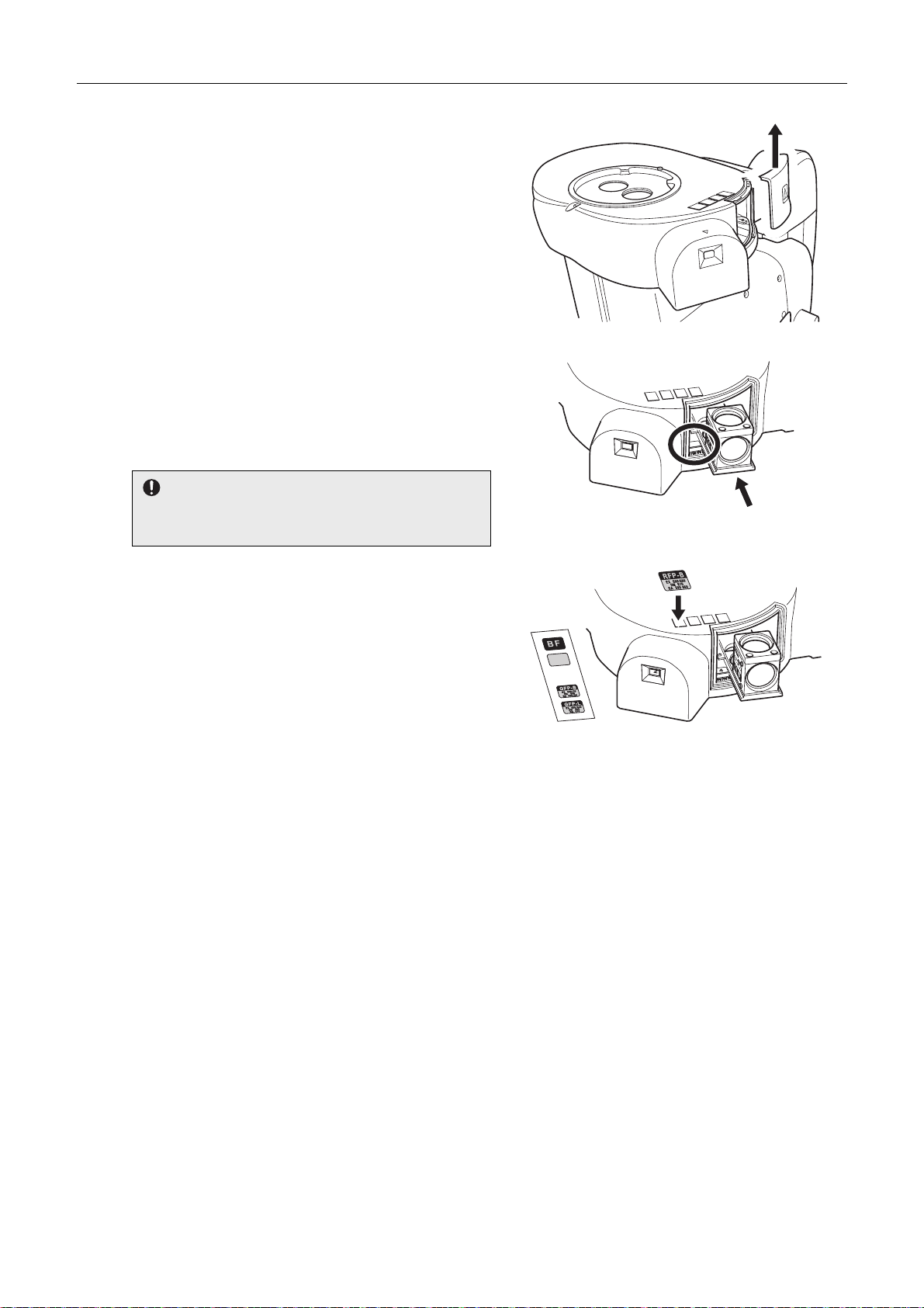
Chapter 5 Assembling
A
(1) Remove the filter cube replacement hole cover on
the right side of the epi fluorescence attachment (as
viewed from the front). Push it upward to remove.
Removing the filter cube replacement hole cover
(2) Align and insert the dovetail groove of the filter cube
to the internal dovetail until it reaches the limit. The
installation positions are numbered from [1] to [4]
and are shown on the left inside of the filter cube
attachment hole.
Be sure to attach four cubes to the turret.
Attach an empty cube to the position to which no filter
cube is attached.
(3) Affix the filter cube indication label.
Labels indicating the type of filter cube are supplied
with the epi fluorescence attachment. It is useful to
identify the type with the labels. Affix a label
indicating the type of attached filter cube to the label
attachment position at the top of the filter cube
attachment hole. Numbers 1 through 4 are indicated
next to the label indents. Affix a label for the
attached filter cube to the indent corresponding to
ffixing a label indicating the type of the filter cube
the filter cube address.
(4) Replace the cover of the filter cube replacement
hole.
2
MADE IN JAPAN
P2-EFLC
2
4
Attaching the filter cube
85
Page 100
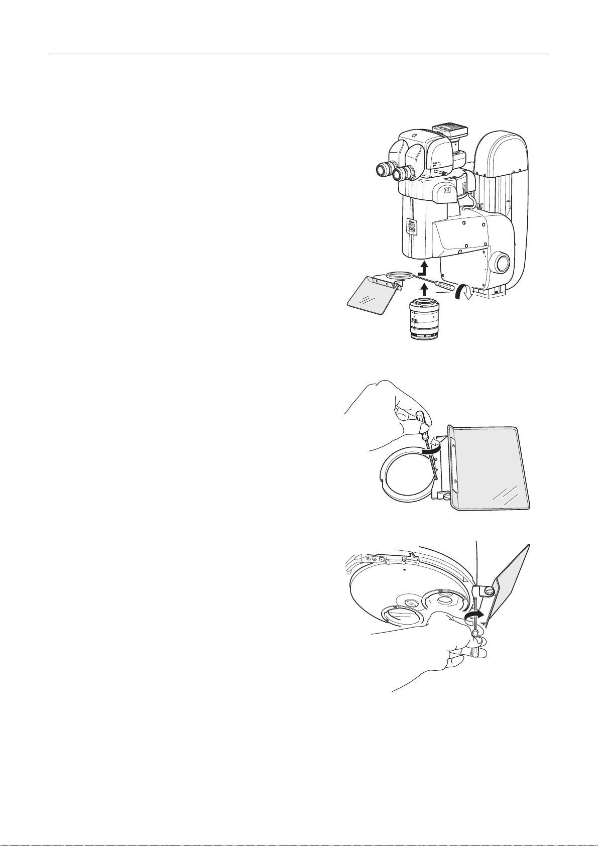
Chapter 5 Assembling
Attaching a light shielding plate
When using a focus mount, attach the light shielding plate to the zooming body, and when using an intelligent
nosepiece, attach it to the bottom of the intelligent nosepiece.
Attachment to the zooming body
Fit the ring of the light shielding plate to the periphery of
the dovetail attachment adapter attached to the lower part
of the zooming body, and firmly tighten the M2.5 hexagon
socket head bolt on the rear side of the ring using a hex
driver (nominal designation: 2).
Attaching to the intelligent nosepiece
(1) Separate the ring attached to the light shielding
plate. The ring is attached to the light shielding plate
with the two M2.5 hexagon socket head bolts.
Remove them using a hex driver (nominal
designation: 2).
(2) Align the screw holes of the light shielding plate with
the two screw holes at the bottom front of the
intelligent nosepiece and firmly attach the light
shielding plate using the two M2.5 hexagon socket
head bolts that were used to affix the ring.
Attaching the shielding plate
by tightening the screw
Removing the ring from the light shielding plate
86
Attaching the shielding plate
by tightening the screws
 Loading...