

Page 1

M350 E 05.4.NF.1
Industrial Microscope
ECLIPSE LV150/LV150A
Instructions
Page 2

Page 3
Thank you for purchasing the Nikon products.
This instruction manual has been prepared for the users of Nikon’s industrial
microscope “ECLIPSE LV150/LV150A.”
To ensure correct usage, read this manual carefully before operating the instrument.
• It is prohibited to reproduce or transmit this manual in part or whole without Nikon’s
expressed permission.
• The contents of this manual are subject to change without notice.
• Although every effort has been made to ensure the accuracy of this manual, if you
note any points that are unclear or incorrect, contact your nearest Nikon
representative.
• Some of the products described in this manual may not be included in the set you
have purchased.
• Be sure to read the instruction manual for any other products that may be used in
combination with the microscope.
Warning/Caution Symbols Used in This Manual
Although Nikon products are designed to provide you with the utmost safety during use,
incorrect usage or disregard of the instructions can cause personal injury or property
damage. For your safety, read this instruction manual carefully and thoroughly before
using the instrument. Do not discard this manual, but keep it near the product for easy
reference.
In this manual, safety instructions are indicated with the symbols shown below. Be sure
to follow the instructions indicated with these symbols to ensure correct and safe
operation.
Symbol Meaning
Disregarding instructions marked with this symbol may lead
WARNING
CAUTION
to death or serious injury.
Disregarding instructions marked with this symbol may lead
to injury or property damage.
Meaning of Symbols Used on the Equipment
Symbol Meaning
Caution for heat.
This marking on the rear of the lamphouse, and near the
lamphouse clamp screw on the illuminator (LV-UEPI and
LV-UEPI2), calls your attention on the following.
For the symbol position, see pages 10 and 12.
• The lamphouse is very hot during and immediately after
illumination.
• Risk of burns. Do not touch the lamphouse during and
immediately after illumination.
• Make sure that the lamphouse has sufficiently cooled
before replacing the lamp.
1
Page 4

WARNING
1. Intended product use
This microscope should only be used for microscopic observation. Do not use it for any
other purpose. Do not observe such a large sample as to stick out of the stage.
2. Do not disassemble.
Disassembly may cause malfunction, electrical shock, and/or injury. Any injury or damage
due to such an act will not be warranted. Do not disassemble any part other than those
described in this manual. If you experience any problem with the microscope, notify your
nearest Nikon representative.
3. Read the instruction manuals carefully.
For your safety, carefully read this manual and the manuals provided with the other products
to be used with the system. Be sure to read warnings and cautions at the beginning of each
manual in particular.
When the external light source is used:
When you use the external light source using a mercury lamp or so on, handle the lamp with
extreme caution. Read the manual for the light source carefully and observe handling
precautions.
4. Ratings of power supply
The power circuit in this instrument is rated for AC power supplies of 100 to 240 V, 50/60
Hz. When connecting the instrument to a power line, check that the line conforms to the
voltage and frequency ratings mentioned above.
Use of a power line that does not satisfy the ratings may lead to equipment malfunction or
damage or a fire.
5. Power cord
Use only the supplied power cord. Using the wrong power cord could result in damage or a
fire. Also, connect the microscope to a PE (protective earth) terminal, since the microscope
complies with the electric shock protection class I.
And besides, to prevent electrical shock, always turn off the power switch (flip it to “ ”
side) before connecting or disconnecting the power cord.
For details about the specified power cord, see “VIII. Specifications.”
6. Specified light source
This microscope must be used with a specified light source. The following light source
combinations are specified for this microscope.
● Illuminator:
Nikon LV-UEPI Universal Epi Illuminator (model LV-UEPI) or Nikon LV-UEPI2
Universal Epi Illuminator (model LV-UEPI2)
● Lamphouse:
Nikon LV-LH50PC precentered lamphouse 12V 50W (model LV-LH50PC)
● Lamp:
Nikon LV-HL50W 12V 50W LONGLIFE halogen lamp (model LV-HL50W), or nonNikon 12V 50W SHORTLIFE halogen lamp (model OSRAM HLX 64610, OSRAM
HLX 64611, or PHILIPS 7027)
If you wish to buy these lamps, contact your nearest Nikon representative.
2
Page 5

WARNING
7. Light source other than the specified ones
To perform the epi-fl microscopy wit the LV-UEPI2 illuminator, the specified light source
brightness may be less than the desired brightness. In this case, a light source other than the
specified ones, an external light source, can be used for the LV-UEPI2.
Use the X-Cite 120 (manual type) or X-Cite 120PC (motorized type) manufactured by
EXFO Electro-Optic Engineering Inc. for the external light source. In particular, when the
LV150A is used for the microscope main body, be sure to attach the X-Cite 120PC to
prevent a flash of light. The X-Cite 120PC must be connected with the LV150A through the
RS-232C cable attached to the light source. When the LV150 is used, either external light
source will work.
Please take note that if a light source other than the specified ones are installed onto this
microscope, this microscope system will not be treated as a TUV/SEMI approved product.
8. Heat from the light source
The lamp and the lamphouse become extremely hot. To avoid burns, do not touch the
lamphouse while the lamp is lit or for thirty minutes after it is turned off.
Furthermore, to avoid the risk of fire, do not place fabric, paper, or highly flammable
volatile materials (such as gasoline, petroleum benzine, paint thinner, or alcohol) near the
lamphouse while the lamp is lit or for about thirty minutes after it is turned off.
9. Air vents
Do not block the air vents on the microscope and lamphouse.
If the air vents are blocked, the temperature of the microscope will raise. And it results in
damage or fire.
10. Ultraviolet light from a light source other than the specified ones
If you use a light source other than the specified ones and that has a mercury lamp or so on,
the light source radiates ultraviolet light that is harmful to the eyes and skin from the
emission port. Direct viewing of light from these lamps may result in snow blindness at a
light case or blindness at worst. To prevent injury, follow the guidelines below.
1) Insert the UV collector lens into the optical path of the microscope unless the
UV excitation light is necessary.
On the illuminator LV-UEPI2, the UV filter automatically enters the optical path when
turning the microscopy selection knob to BF (bright-field) or DF (dark-field). The UV
filter is removed from the optical path when turning the knob to FL1 (epi-fl 1) or FL2
(epi-fl 2).
2) When performing the epi-fl microscopy by using the UV excitation light, attach
the filter cube dedicated to the UV excitation light. And then, if you must see
the objective or its surroundings, be sure to see through the ultraviolet light
shield.
3) Attach the light source to the microscope during use.
Always attach the light source to the microscope when the light source is ready to turn
on. Do not turn on the light source unattached to the microscope, or remove the light
source from the microscope while the light source is lit. When removing the light source
from the microscope, turn off the power to the light source, and then unplug the power
code from the wall outlet.
11. Reflection
Lustrous samples reflect the illumination. Do not observe the illuminated surface of a
sample for a long time because the strong reflection may hurt your eyes. When you use the
illuminator LV-UEPI2, be sure to view it through the ultraviolet light shield.
3
Page 6

CAUTION
1. Handle the system gently
2. Do not wet the microscope
3. Weak electromagnetic waves
4. Installation location
Components of this system are precision optical instruments. Handle them carefully, and do
not subject them to any shocks.
The precision of the objectives in particular can be adversely affected even by weak shocks.
If the microscope gets wet, a short circuit may cause malfunction or abnormal heating of the
microscope. If you accidentally spill water on the microscope, immediately turn off the
power switch (flip it to the “ ” side) and unplug the power cord from the wall outlet. Then,
wipe away the moisture using a dry cloth or the like. If water gets inside the microscope, do
not use it; instead, notify your nearest Nikon representative.
This microscope emits weak electromagnetic waves. The accuracy of any precision
electronic equipment may be adversely affected if positioned too close. If the microscope
affects TV or radio reception, move the radio or TV farther away from the microscope.
Being a precision optical instrument, the microscope may get damaged or loose accuracy if
it is used or stored under unsuitable conditions. When selecting the installation location,
note the following:
• Avoid a brightly lit location, such as exposed to direct sunlight or directly under a room
light. The image quality deteriorates if there is excessive ambient light.
Always install the microscope with a surrounding clear area of 10 cm or more.
• Choose a location that is free from dust or dirt.
• Choose a flat surface with little vibration.
• Choose a sturdy desk or table that is able to bear the weight of the instrument.
• Do not install the microscope in a hot or humid location.
• Select a layout that allows easy removal of the power cord from the microscope’s AC inlet
in the event of an emergency.
• For details about the operating environment and storage environment, see “VIII.
Specifications.”
• Take enough space around the microscope referring to the layout diagrams on page 6.
• The microscope may be moved by earthquakes. We recommend taking anti-earthquake
measures.
For details about the anti-earthquake measures, see “15. Countermeasures for
Earthquakes” in “IV. Assembly.”
5. Cautions on moving the microscope
• The microscope is a precision optical instrument. Handle it carefully and do not subject it
to a strong physical shock. (In particular, objectives may loose accuracy when exposed to
even a weak physical shock.)
• When moving the microscope, first remove the stage and the lamphouse. Then, securely
hold the microscope by the root of the arm from the back.
(Information) The microscope with the stage, eyepiece tube, lamphouse, and other parts
attached, weighs approx. 20 kg.
• Do not hold the focusing knobs, eyepiece tube, lamphouse, sub-stage, etc., when carrying
the microscope. They may come off and may cause serious injury or malfunction.
• Before carrying the stage, attach the fixing metals to hold the movement of the stage plate.
• Be careful not to pinch your fingers or hands during transportation.
4
Page 7

CAUTION
6. Cautions on assembling the microscope
7. Cautions on lamp replacement
8. Handing of filter cubes
• Be careful not to pinch your fingers or hands during assembly.
• Scratches or fingerprints on the lens surface will adversely affect the microscope image.
Be careful not to scratch or touch the lens surfaces.
• To prevent burn injury, allow the lamp to cool down sufficiently (for at least 30 minutes
after it is turned off) before replacing the lamp.
• To prevent electrical shock and damage to the microscope, always turn off the power
switch (flip it to the “ ” side) and unplug the power cord from the wall outlet before
connecting or disconnecting the lamphouse.
• Do not touch the glass surface of the lamp with bare hands. Fingerprints or grease on the
bulb surface will reduce the illumination intensity of the lamp. Wipe out any fingerprints
or grease attached to the surface.
• Securely attach the lamphouse cover to the lamphouse after replacing the lamp. Never
light the lamp while the lamphouse cover is open.
• When you dispose of the replaced lamp, do not break it up. Instead, dispose of the used
lamp as special industrial waste or dispose of it according to the local regulations and
rules.
When using the microscope configured with the illuminator LV-UEPI2, a filter cube can be
attached to enable epi-fl microscopy. Note the following precautions for handling a filter
cube.
• Interference filters (in particular, excitation filters exposed to intense light) are subject to
aging. Replace them depending on their total operating hours.
• Filters can change in characteristics under high humidity. To avoid changes in
characteristics and quality, do not use or store filters at high temperatures or high
humidity, or expose them to rapid temperature changes. When not using filters, they
should be stored with a drying agent in desiccators or sealed containers.
• The filters fitted in the nine types of filter cubes listed below have sharper wavelength
characteristics than ordinary filters. However, these filters should be handled with care as
they are applied with complicate coating. In particular, be cautious against wear during
cleaning. (Observe the procedures described in “Cleaning Filters and Lenses” of “VII.
Care and Maintenance.”)
Single-band filter cubes: DAPI, FITC, TxRed, and GFP
Multi-band filter cubes: F-R, F-T, D-F, D-F-R, and D-F-T.
5
Page 8
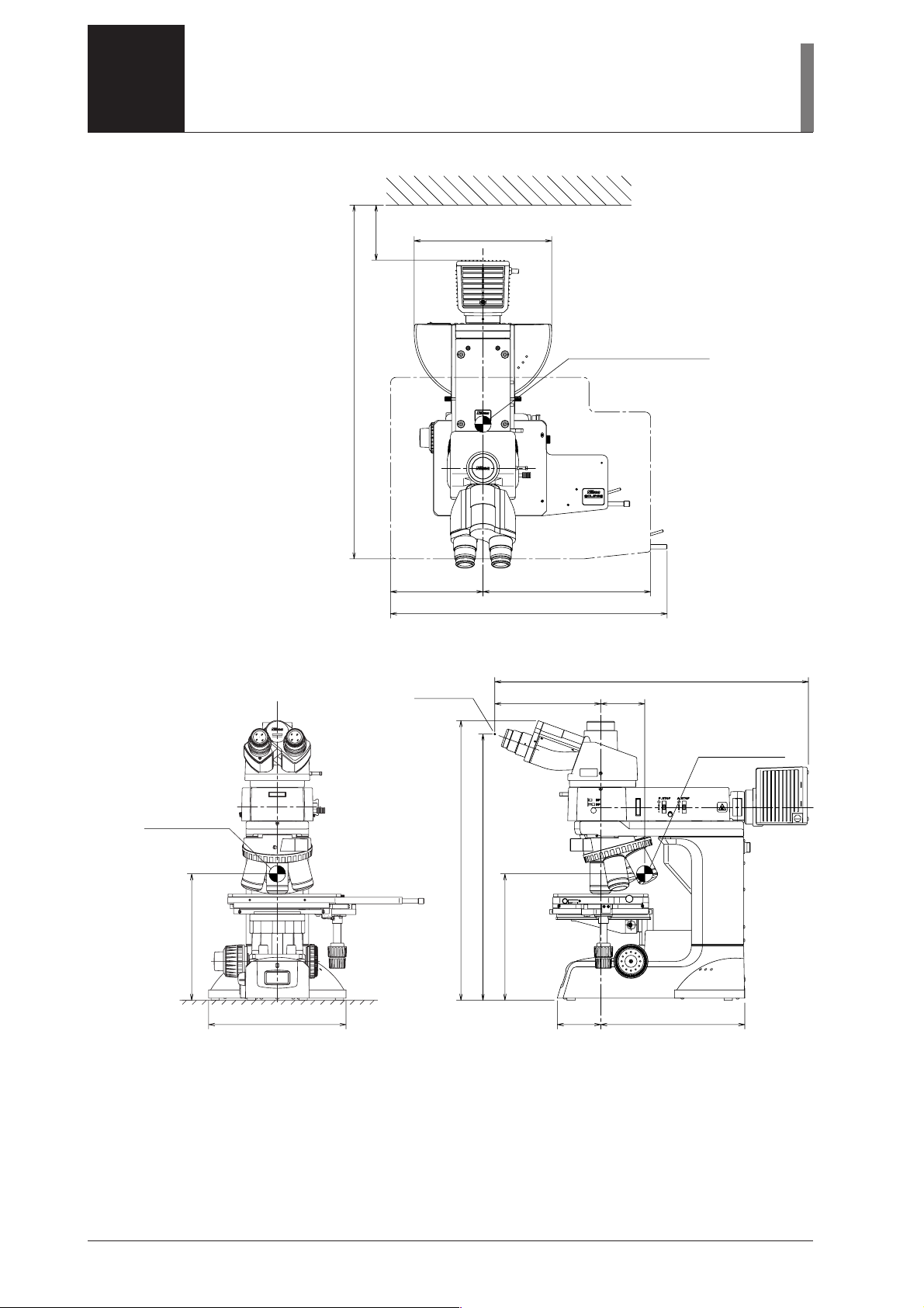
LAYOUT DIAGRAMS
100
643
(Stage area)
250
168 305
503
(Stage area)
Eye point
Center of gravity position
6 x 6 STAGE
JAPAN
570.4
80192.6
Center of
gravity position
230
This illustration depicts the LV150A microscope configured with the LV-UEPI illuminator, LVTI3 eyepiece tube, LV-LH50PC lamphouse, and 6x6 stage.
508.5
Center of
gravity position
484
230
26279250
Dimensions are in mm.
6
Page 9
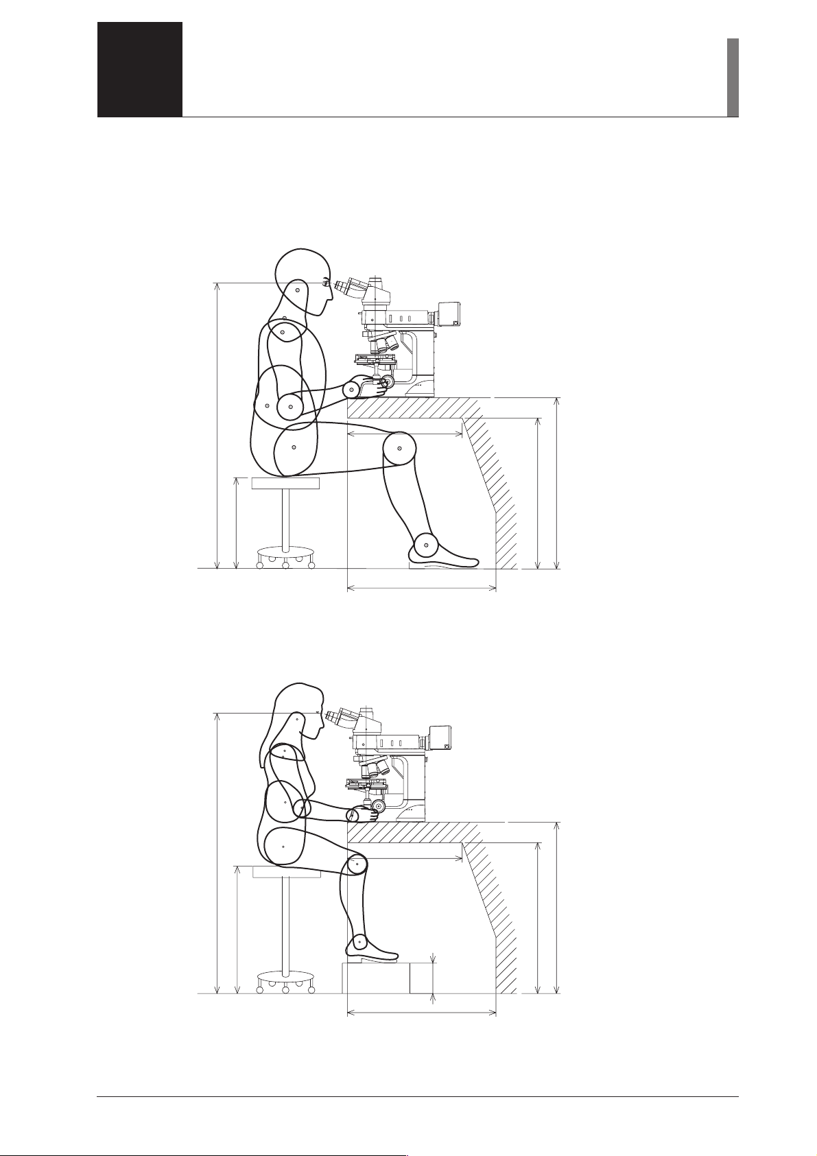
OPERATING POSTURE
The figure below shows the operating posture that prevents strain on your body.
Choose a workbench and a chair having similar dimensions to those shown in the figure.
The 95th percentile male (Height: 189.5 cm)
510
1269 (The height of the eyepiece height point)
405 (The height of the seating surface)
660
* The height of the eye point is that when one eye-level riser is mounted on the microscope.
* Take at least 610 mm of horizontal clearance for your legs.
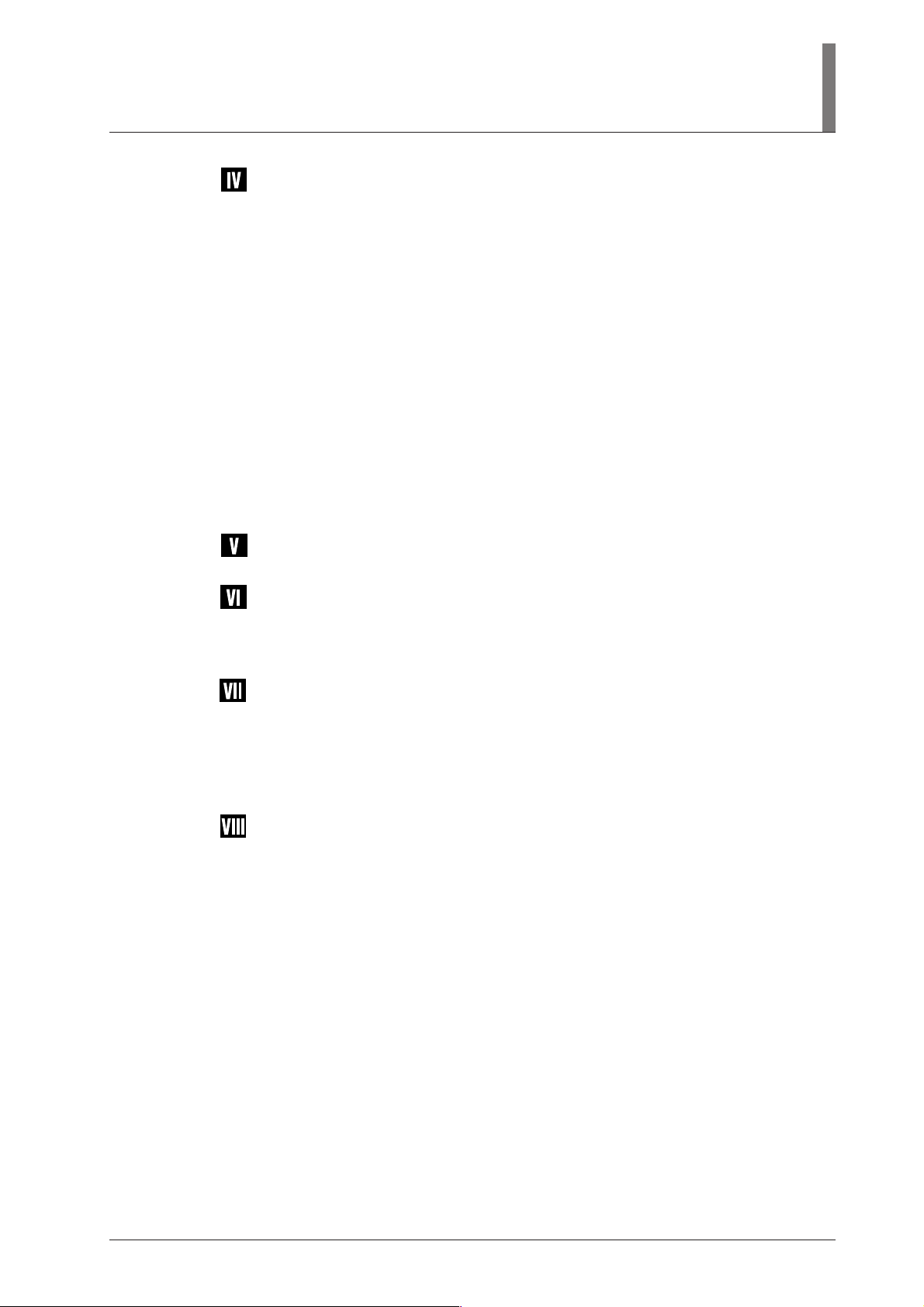
The 5th percentile female (Height: 147.5 cm)
510
673
760
Dimensions are in mm.
1244 (The height of the eyepiece height point)
565 (The height of the seating surface)
660
* Take at least 610 mm of horizontal clearance for your legs.
135
673
760
Dimensions are in mm.
7
Page 10

CONTENTS
Warning/Caution Symbols Used in This Manual .............................................. 1
Meaning of Symbols Used on the Equipment .................................................. 2
WARNING ......................................................................................................... 2
CAUTION .......................................................................................................... 4
LAYOUT DIAGRAMS ........................................................................................... 6
OPERATING POSTURE ....................................................................................... 7
Names of Each Part ................................................................................... 10
1When Configured with the Illuminator LV-UEPI ........................................................... 10
2When Configured with the Illuminator LV-UEPI2 ......................................................... 12
3Rear View ........................................................................................................................ 14
Microscopy................................................................................................. 15
1 Bright-Field Microscopy ................................................................................................. 16
2 Dark-Field Microscopy ................................................................................................... 18
3 Differential Interference Contrast (DIC) Microscopy ..................................................... 20
4 Simplified Polarization Microscopy................................................................................ 22
5 Sensitive Polarization Microscopy .................................................................................. 24
6 Epi-Fluorescence Microscopy ......................................................................................... 25
Operation of Each Part.............................................................................. 26
1 Operation of the Illumination .......................................................................................... 26
2 Filters ............................................................................................................................... 26
3 Coarse/Fine Focus Knobs................................................................................................ 27
4 Eyepiece Tube ................................................................................................................. 29
5 Diopter Adjustment ......................................................................................................... 30
6 Interpupillary Distance Adjustment ................................................................................ 30
7 Field Diaphragm .............................................................................................................. 31
8 Aperture Diaphragm ........................................................................................................ 32
9 Illumination Selection Lever and Microcopy Selection Knob ........................................ 33
10 Stage ................................................................................................................................ 34
11 Motorized Nosepiece Operation ...................................................................................... 35
12 Polarizer Slider ................................................................................................................ 36
13 Lambda Plate Slider (for the LV-UEPI2 only) ................................................................ 37
14 Analyzer Slider ................................................................................................................ 38
15 DIC Slider ....................................................................................................................... 39
16 Filter Cubes for Fluorescence Observation (for the LV-UEPI2 only) ............................. 40
17 Excitation Light Balancer (for the LV-UEPI2 Only) ....................................................... 43
8
Page 11
Assembly.................................................................................................... 45
1 Attaching the Stage and the Holder................................................................................. 47
2 Assembling the Nosepiece .............................................................................................. 48
3Attaching the Illuminator ................................................................................................ 50
4 Attaching the Lamphouse and Replacing the Lamp ....................................................... 53
5 Attaching the Fiver Adapter and External Light Source ................................................. 54
6 Attaching the Eyepiece Tube........................................................................................... 56
7 Attaching Eyepieces ........................................................................................................ 56
8 Attaching Objectives ....................................................................................................... 56
9 Attaching Eye Level Riser .............................................................................................. 57
10 Attaching Column Riser .................................................................................................. 57
11 Connecting the Power Cord ............................................................................................ 58
12 Connecting the RS-232C ................................................................................................. 58
13 Installing Separately Sold Accessories ............................................................................ 58
14 Anti-static Treatment ....................................................................................................... 58
15 Countermeasures for Earthquakes ................................................................................... 59
External Communications Control........................................................... 60
Troubleshooting ......................................................................................... 66
1Viewing and control systems ........................................................................................... 66
2 Electrical.......................................................................................................................... 69
Care and Maintenance .............................................................................. 70
1 Cleaning Lenses and Filters ............................................................................................ 71
2 Cleaning the Painted, Plastic, and Printed Parts.............................................................. 71
3 Storage ............................................................................................................................. 71
4Regular Inspections ......................................................................................................... 71
Specifications ............................................................................................ 72
9
Page 12
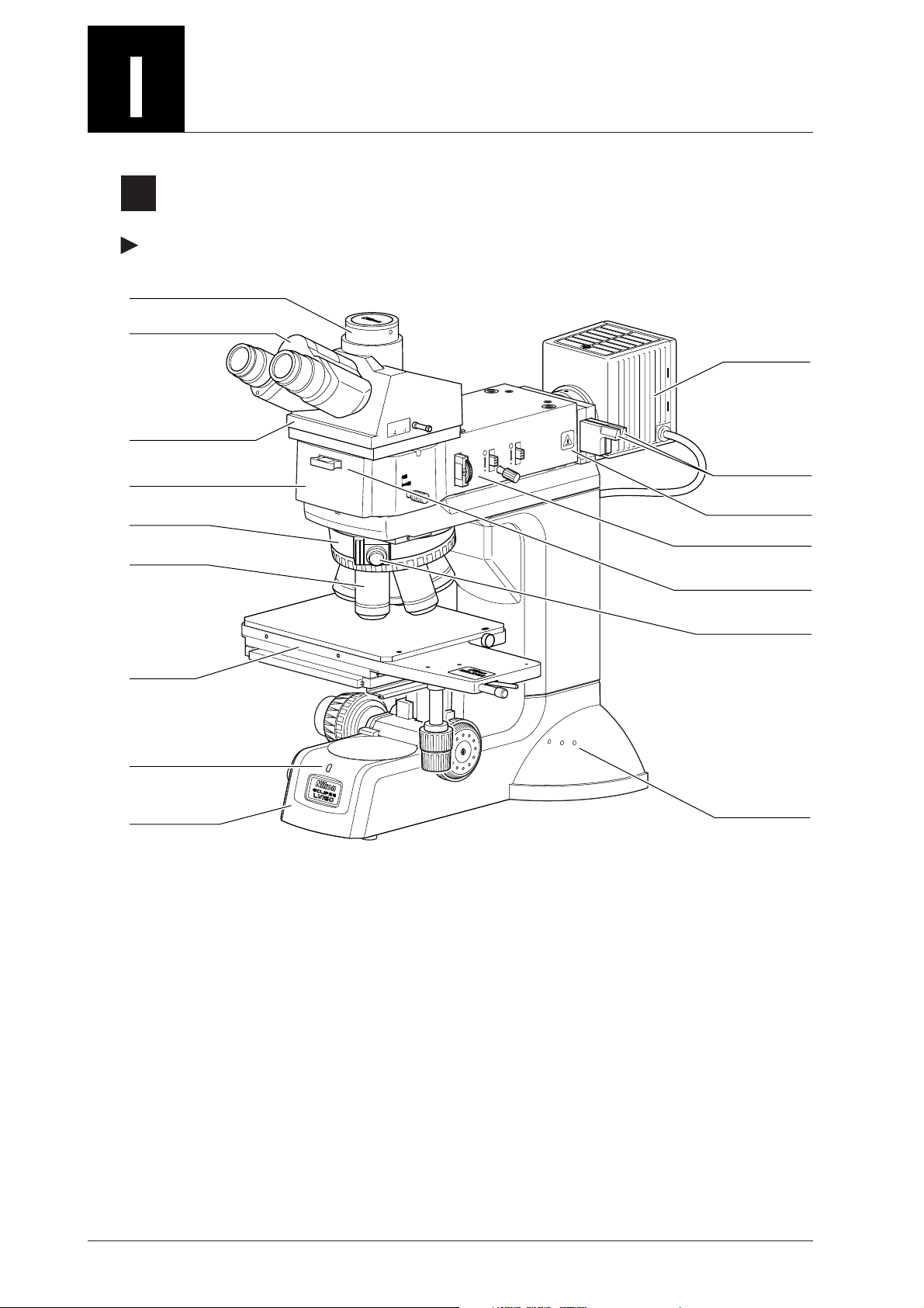
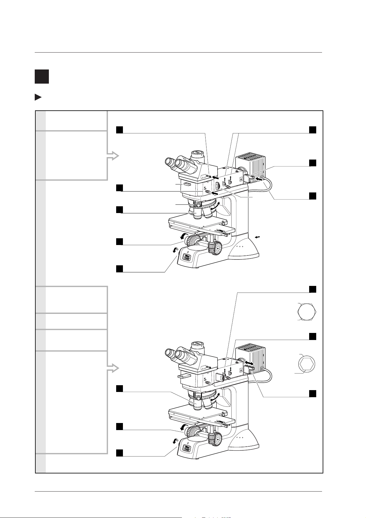
Names of Each Part
1
When Configured with the Illuminator LV-UEPI
Names of Parts
Vertical tube
Binocular part
T
OU
IN
100
0
0
Eyepiece tube LV-TI3
Illuminator LV-UEPI
Nosepiece
Objective
100
BF
DF
STOP A
.
F
STOP
.
Lamphouse
Filter sliders
“CAUTION for
heat” symbol
Polarizer slider
Analyzer slider
*1
*1
Stage
Power indicator
Main body of
the microscope
This drawing depicts the ECLIPSE LV150A microscope configured with the LV-UEPI
illuminator, LV-TI3 eyepiece tube, LV-LH50PC lamphouse, 6x6 stage, and attachments for DIC
microscopy.
DIC slider
6
x
6 STAGE
JAPAN
Tool holders
*1: For DIC microscopy or simplified polarization microscopy.
*2: For DIC microscopy.
*2
10
Page 13
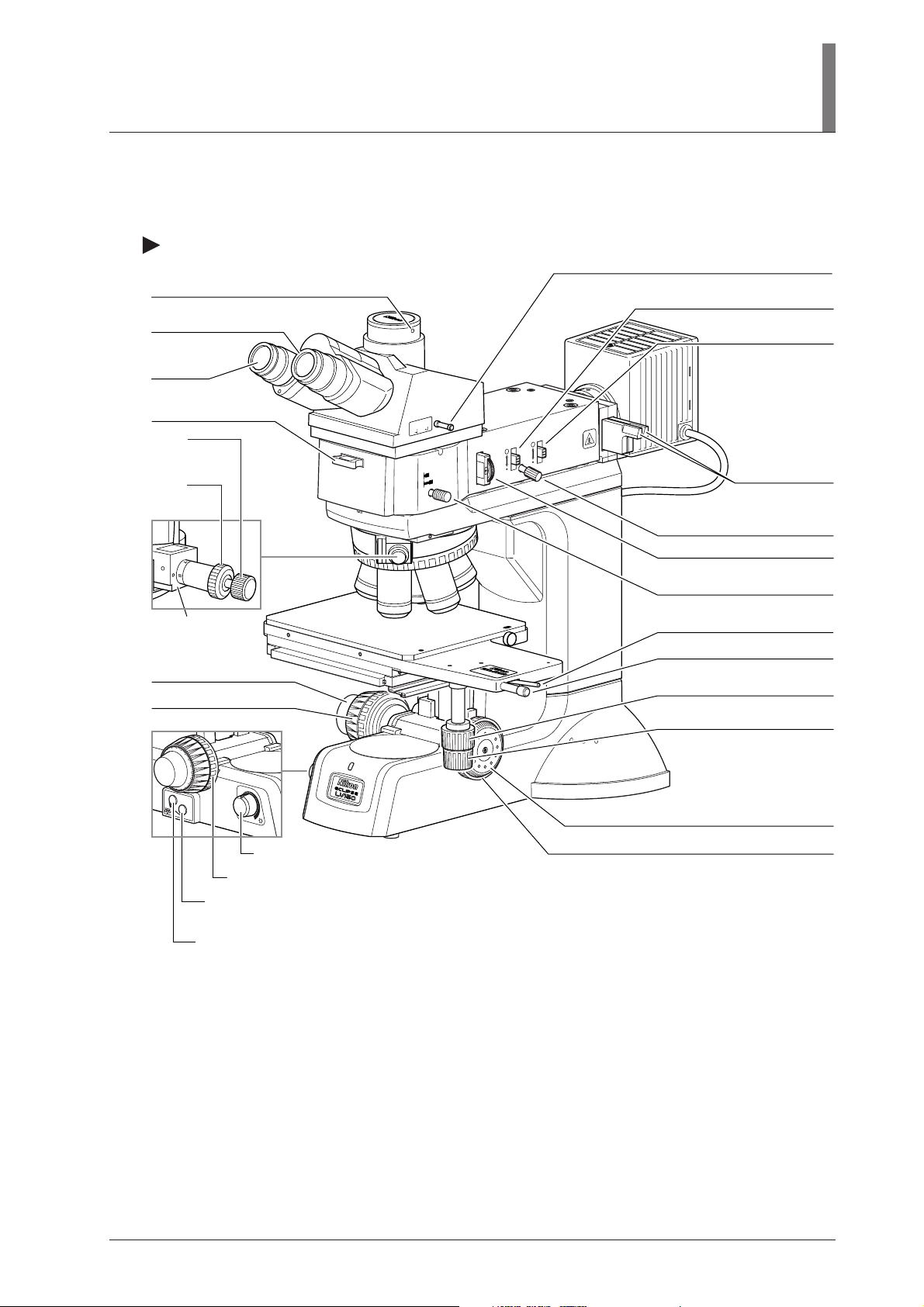
Names of Operational Parts
Clamp screw for various adapters
Diopter adjustment ring
Eyepiece
I. Names of Each Part
Optical path selection lever
Field diaphragm open/close lever
Aperture diaphragm
open/close lever
Analyzer slider
*1
Prism
movement
knob
Prism
selection
knob
DIC slider
*2
Fine focus knob
Coarse focus knob
OBJ.
Coarse torque adjustment ring
Nosepiece rotation button (on LV150A only)
Rotates the nosepiece counterclockwise (when seen from above the microscope).
Nosepiece rotation button (on LV150A only)
Rotates the nosepiece clockwise (when seen from above the microscope).
OFF
Brightness control knob
OUT
IN
100
0
0
100
BF
DF
STOP A
.
F
STOP
.
Filter sliders
Field diaphragm centering screw
Polarizer slider
*1
Bright/dark-field illumination
selection lever
Stage coarse/fine movement
selection switch
Stage coarse movement lever
6
x
6 STAGE
JAPAN
Stage fine movement knob
for Y-axis
Stage fine movement knob
for X-axis
Fine focus knob
Coarse focus stopper ring
*1: For DIC microscopy or simplified polarization microscopy.
*2: For DIC microscopy.
This drawing depicts the ECLIPSE LV150A microscope configured with the LV-UEPI
illuminator, LV-TI3 eyepiece tube, LV-LH50PC lamphouse, 6x6 stage, and attachments for DIC
microscopy.
11
Page 14
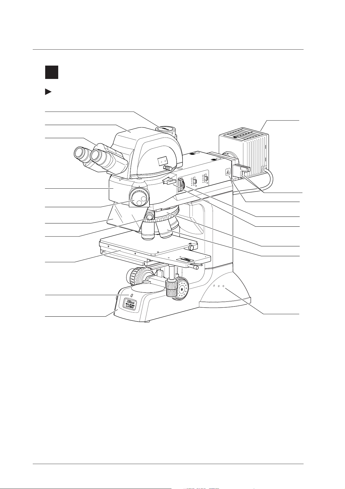
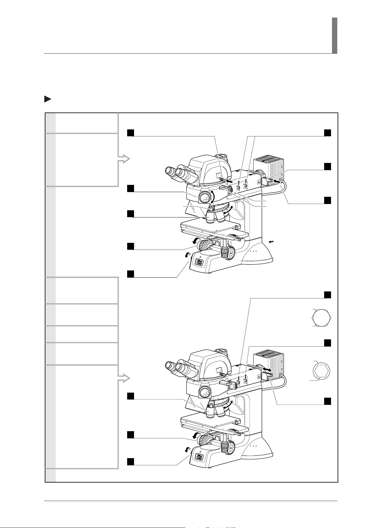
2
When Configured with the Illuminator LV-UEPI2
Names of Parts
Vertical tube
Eyepiece tube LV-TT2
Binocular part
UT
O
IN
100
0
100 20
TT2
LV-
JA
P
Illuminator LV-UEPI2
Microscopy selection knob
Ultraviolet light shield
DIC slider
*3
AN
BF
FL2
DF
S
FL1
STOP
.
A
STOP
.
F
Lamphouse
Filter sliders
“CAUTION for heat” symbol
Polarizer slider
Dummy slider
Analyzer slider
*1
*2
*1
Nosepiece
6
x
6 STAGE
Stage
JAPAN
Power indicator
Main body of the microscope
*1: For DIC microscopy, simplified polarization microscopy, or sensitive polarization microscopy.
*2: Lambda plate slider in case of sensitive polarization microscopy.
*3: For DIC microscopy.
This drawing depicts the ECLIPSE LV150A microscope configured with the LV-UEPI2 illuminator,
LV-TT2 eyepiece tube, LV-LH50PC lamphouse, 6x6 stage, and attachments for DIC microscopy.
Objective
Tool holders
12
Page 15
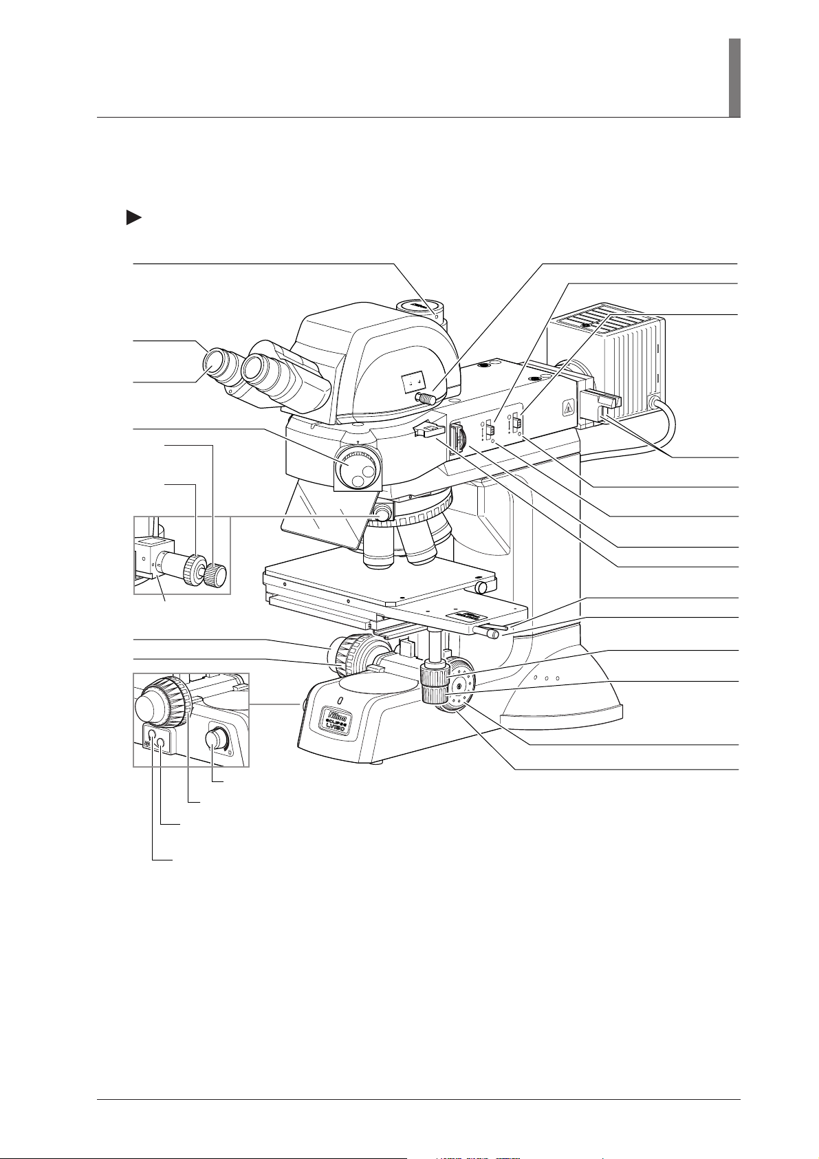
Names of Operational Parts
I. Names of Each Part
Clamp screw for various adapters
Diopter
adjustment
ring
Eyepiece
Microscopy selection knob
Prism
movement
knob
Prism
selection
knob
DIC slider
*2
Fine focus knob
Coarse focus knob
Optical path selection lever
Field diaphragm open/close lever
Aperture diaphragm
open/close lever
OUT
IN
100
0
100 20
LV-TT2
J
A
P
A
N
BF
FL2
DF
S
FL1
STOP
.
A
STOP
.
F
Filter sliders
Aperture diaphragm centering
screw (on both sides)
Field diaphragm centering
screw (on both sides)
Polarizer slider
Dummy slider
Analyzer slider
*1
*2
*1
Stage coarse/fine movement
selection switch
6
x
6 STAGE
JAPAN
Stage coarse movement lever
Stage fine movement knob
for Y-axis
Stage fine movement knob
for X-axis
OBJ.
OFF
Fine focus knob
Coarse focus stopper ring
Brightness control knob
Coarse torque adjustment ring
Nosepiece rotation button (on LV150A only)
Rotates the nosepiece counterclockwise (when seen from above the microscope).
Nosepiece rotation button (on LV150A only)
Rotates the nosepiece clockwise (when seen from above the microscope).
*1: For DIC microscopy, simplified polarization microscopy, or sensitive polarization microscopy.
*2: Lambda plate slider in case of sensitive polarization microscopy.
*3: For DIC microscopy.
This drawing depicts the ECLIPSE LV150A microscope configured with the LV-UEPI2 illuminator,
LV-TT2 eyepiece tube, LV-LH50PC lamphouse, 6x6 stage, and attachments for DIC microscopy.
13
Page 16
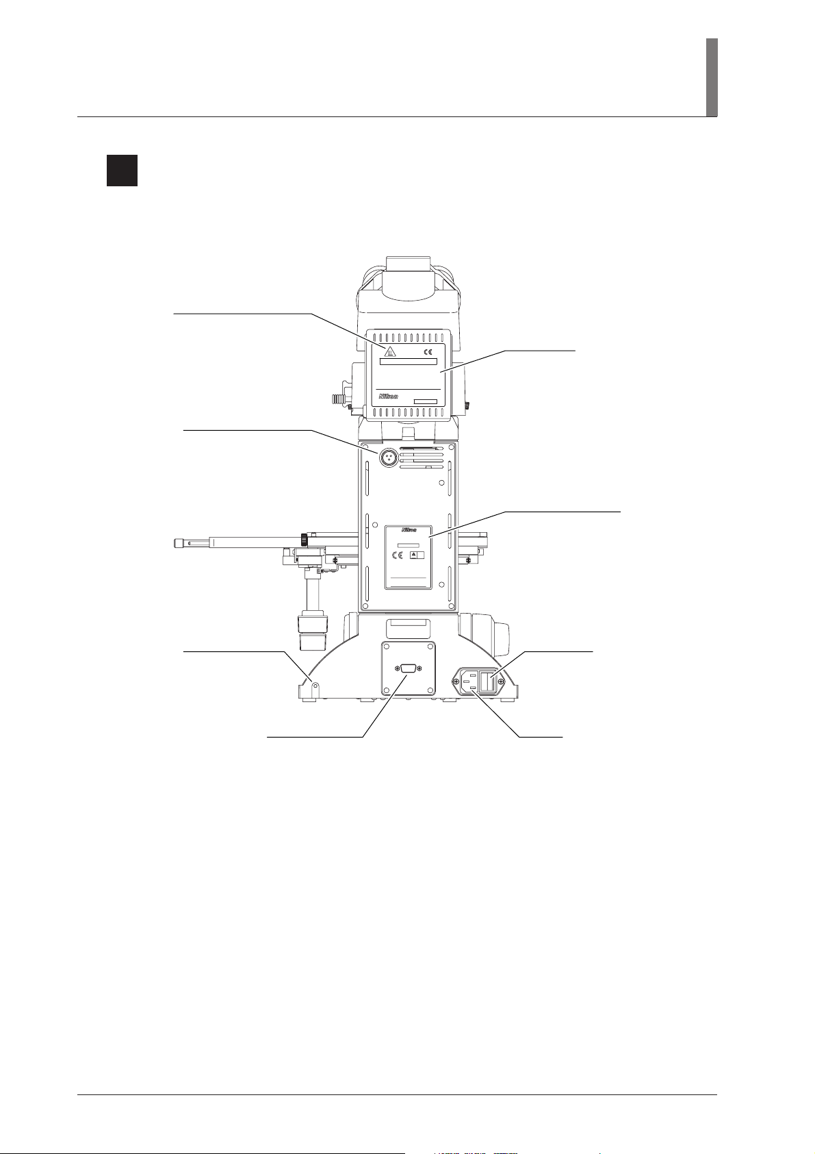
3
Rear View
“CAUTION for heat” symbol
Connector for connecting
the lamphouse
- High Temperature -
CAUTION !
1.
Do not touch the lamphouse while the lamp is lit.
The surface of the lamphouse becomes hot when
the lamp is on.
2.
Turn off the power and allow the lamp and lamphouse to cool enough before replacing the lamp.
Wait for at least 30 minutes after turning off
the lamp
Use 12V50W HALOGEN lamp only.
3.
HALOGEN 12V50W
LV-LH50PC
JAPAN
652701
LAMP
DC12V 50W
I. Names of Each Part
Caution label
Input voltage indication
ECLIPSE LV150A
100–240V~ 1.2A 50/60Hz
MADE IN JAPAN
510001
SEMI® S2
certified by
TÜV Rheinland
TÜV
including interference that may cause
undesired operation.
This Class A digital apparatus complies with
Canadian ICES-003.
Cet appareil numérique de la classe A est
confirme à la norme NMB-003 du Canada.
Grounding tap (M4)
RS232C
RS232C connector
Power switch
AC inlet
This drawing depicts the ECLIPSE LV150A microscope configured with the LV-UEPI
illuminator, LV-TI3 eyepiece tube, LV-LH50PC lamphouse, and 6x6 stage.
14
Page 17

Microscopy
This chapter describes the procedures for each microscopy.
This microscope can be configured with two types of illuminators, LV-UEPI or LV-UEPI2. See the
table below for the microscopies available with each illuminator, as well as the optional accessories
required for each microscopy.
● If the microscope has not yet been assembled, see “IV. Assembly” on p.45 first.
● See “III. Operation of Each Part” on p.26 for how to operate each part of the microscope.
Microscope
Bright-field
microscopy
Dark-field
microscopy
Differential
interference
contrast (DIC)
microscopy
Simplified
polarization
microscopy
Sensitive
polarization
microscopy
Procedure
p.16 to 17
p.18 to 19
p.20 to 21
p.22 to 23
p.24
Illuminators
LV-UEPI
LV-UEPI2
LV-UEPI
LV-UEPI2
LV-UEPI
LV-UEPI2
LV-UEPI
LV-UEPI2
LV-UEPI2
Required accessories (optional)
–
BD objective
BD quintuple nosepiece, universal quintuple nosepiece
or motorized universal quintuple nosepiece*
(The standard sextuple nosepiece cannot be used
for dark-field microscopy.)
Polarizer
Analyzer
DIC slider
Universal quintuple nosepiece or motorized universal
quintuple nosepiece*
Objectives marked “LU”
(Objectives marked “LU” are suitable for DIC
microscopy.)
Polarizer
Analyzer
Polarizer
Lambda plate
Analyzer
Epifluorescence
microscopy
p.25
LV-UEPI2
Filter cube
(Up to two cubes can be attached.)
Fluorescence excitation light balance filter (optional)
* For the LV150A only.
15
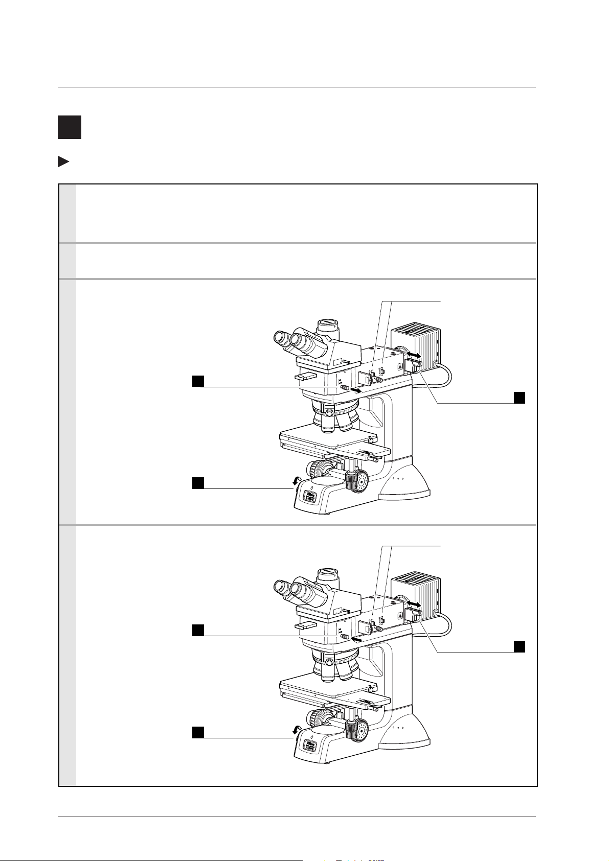
Page 18
1
Bright-Field Microscopy
When configured with the LV-UEPI
1. Turn on the power.
Push in.
1
2. Set the microscope for
bright-field microscopy
If accessories for DIC
microscopy (*1 to *3)
are in place, pull them
out of the optical path.
3. Place the sample on the
stage and focus on it.
(p.27)
Binocular eyepiece: 100% (P.29)
Push in.
2
BF (bright-field) (p.33)
Select the
10x objective.
3
On the LV150A,
use the nosepiece
rotation buttons. (p.35)
Lower the stage
as far as it will go.
4
Coarse focus knob
(p.27)
Adjust the
brightness.
5
Brightness control
knob (p.26)
Raise the levers.
6
To fully open the field and
aperture diaphragms.
(p.31 and p.32)
Push in the
NCB11 filter.
T
U
NO
I
0
0
01
0
0
0
1
*1
BF
DF
STOP
STOP A
.
F
*3
*2
6
x
6
S
J
A
T
A
P
A
G
N
E
To compensate
color temperature.
Adjust the
brightness.
ND filter
7
(p.26)
8
(p.26)
Power switch
Adjust to circumscribe
the viewfield.
Field diaphragm (p.31)
Image of field diaphragm
4
4. Adjust the diopter. (p.30)
5. Adjust the interpupillary
distance. (p.30)
6. Change the magnification
and observe the sample.
Hint:
It may be difficult to
focus on a sample with
small contrast, such on a
polished surface. In a
case like this, stop down
the field diaphragm so
that its image can be
seen in the viewfield,
and try to focus on the
rim of the diaphragm
image. When the rim is
in focus, the sample is in
focus just as well.
Select the
10x objective.
1
On the LV150A,
use the nosepiece
rotation buttons.
(p.35)
Finely adjust
the focus.
2
Coarse/fine focus
knob (p.27)
Adjust the
brightness.
3
Brightness control
knob (p.26)
Viewfield
Adjust to 70 to 80% of
the objective’s N.A.
Aperture diaphragm
Objective’s
pupil
T
U
IN O
0
0
01
0
0
0
1
BF
DF
STOP
.
A
STOP
.
F
Image of
aperture
diaphragm
5
(p.32)
Adjust
the brightness.
ND filter
6
x
6
S
J
A
T
A
P
A
G
N
E
6
(p.26)
16
Page 19
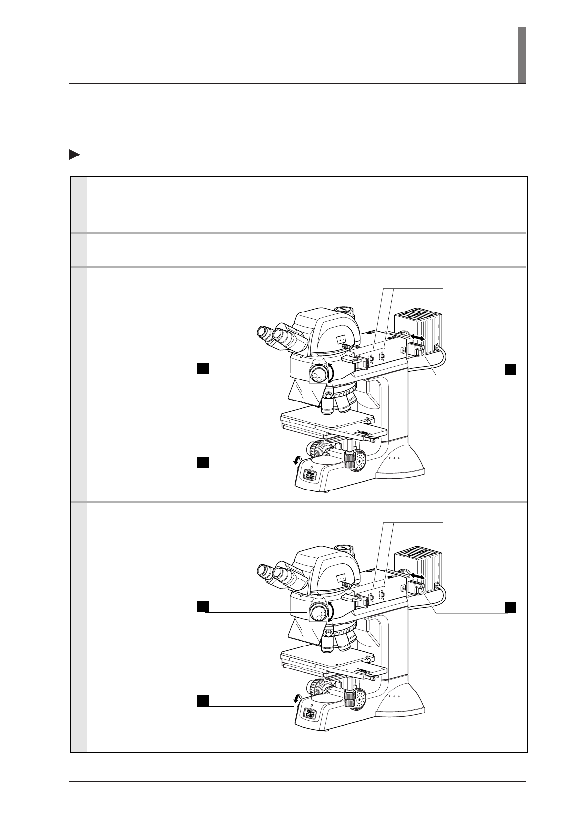
When configured with the LV-UEPI2
1. Turn on the power.
Push in.
1
2. Set the microscope for
bright-field microscopy.
If accessories for DIC or
polarization microscopy
(*1 to *3) are in place,
pull them out of the
optical path.
3. Place the sample on the
stage and focus on it.
(p.27)
4. Adjust the angle of the
binocular part. (p.29)
5. Adjust the diopter. (p.30)
6. Adjust the interpupillary
distance. (p.30)
7. Change the magnification
and observe the sample.
Hint:
It may be difficult to
focus on a sample with
small contrast, such on a
polished surface. In a
case like this, stop down
the field diaphragm so
that its image can be
seen in the viewfield,
and try to focus on the
rim of the diaphragm
image. When the rim is
in focus, the sample is in
focus just as well.
Binocular eyepiece: 100% (P.29)
Turn the
microscopy
selection knob.
2
BF (bright-field) (P.33)
Select the
10x objective.
3
On the LV150A,
use the nosepiece
rotation buttons. (p.35)
Lower the stage
as far as it will go.
4
Coarse focus knob
(p.27)
Adjust the
brightness.
5
Brightness control
knob (p.26)
Select the desired
magnification.
1
On the LV150A,
use the nosepiece
rotation switch.
(p.35)
Finely adjust
the focus.
2
Coarse/fine focus
knob (p.27)
Adjust the
brightness.
3
Brightness control
knob (p.26)
II. Microscopy
Raise the levers.
To fully open the field and
aperture diaphragms.
(p.31 and p.32)
Push in the
NCB11 filter.
T
U
O
N
I
0
0
1
0
0
2
0
0
1
2
T
T
-
V
L
JAP
A
N
BF
FL2
DF
S
FL1
*2
STOP
.
A
STOP
.
F
*3
*1
6
x
6
ST
JAP
AG
AN
E
To compensate
color temperature.
Adjust the
brightness.
ND filter
Power switch
Adjust to circumscribe
the viewfield.
Field diaphragm (p.31)
Image of field diaphragm
Viewfield
Adjust to 70 to 80% of
the objective’s N.A.
Aperture diaphragm
Objective’s
T
U
O
IN
0
0
1
0
0
2
0
0
1
2
T
-T
V
L
JAPA
N
BF
FL2
DF
S
FL1
STOP
.
A
STOP
.
F
pupil
Image of
aperture
diaphragm
Adjust
the brightness.
ND filter
6
x
6
STAGE
JAP
AN
6
7
(p.26)
8
(p.26)
4
5
(p.32)
6
(p.26)
17
Page 20
2
Dark-Field Microscopy
When configured with the LV-UEPI
1. Mount BD objectives and a BD quintuple nosepiece, universal quintuple nosepiece, or motorized universal quintuple nosepiece.
(p.56 and 49)
The standard sextuple nosepiece cannot be used for dark-field microscopy.
2. Focus on the sample with bright-field microscopy. (p.16)
3. Set the microscope for dark-field microscopy.
Pull out.
1
DF (dark-field) (P.33)
Adjust the
brightness.
2
Brightness control
knob (p.26)
4. Return the microscope to bright-field microscopy.
Push in.
1
BF (bright-field) (p.33)
The field and aperture
diaphragms are fully
opened automatically.
(However, the lever
positions are not
changed.)
T
U
IN O
0
0
01
0
0
0
1
BF
DF
STOP
.
A
STOP
.
F
Adjust the
brightness.
3
ND filter (p.26)
6
x
6
S
J
A
T
A
P
A
G
N
E
The field and aperture
diaphragms automatically return to what they
were before the microscope was set to darkfield microscopy.
T
U
O
IN
0
0
01
0
0
0
1
BF
DF
STOP
.
A
STOP
.
F
Adjust the
brightness.
3
ND filter (p.26)
18
Adjust the
brightness.
2
Brightness control
knob (p.26)
6
x
6
S
J
A
T
A
P
A
G
N
E
Page 21
II. Microscopy
When configured with the LV-UEPI2
1. Mount BD objectives and a BD quintuple nosepiece, universal quintuple nosepiece, or motorized universal quintuple nosepiece.
(p.56 and 49)
The standard sextuple nosepiece cannot be used for dark-field microscopy.
2. Focus on the sample with bright-field microscopy. (p.17)
3. Set the microscope for dark-field microscopy.
Turn the
microscopy
selection knob.
1
DF (dark-field) (p.33)
Adjust the
brightness.
2
Brightness control
knob (p.26)
4. Return the microscope to bright-field microscopy.
Turn the
microscopy
selection knob.
1
BF (bright-field) (p.33)
The field and aperture
diaphragms are fully
opened automatically.
(However, the lever
positions are not
T
U
O
IN
00
1
0
0
2
0
0
1
2
T
-T
V
L
J
A
PA
N
DF
BF
FL2
BF
DF
FL2
S
S
FL1
FL1
STOP
.
A
STOP
.
F
6
x
6 ST
JAPAN
AGE
changed.)
Adjust the
brightness.
ND filter (p.26)
3
The field and aperture
diaphragms
automatically return to
what they were before
the microscope was
T
U
O
IN
0
0
1
0
0
2
0
0
1
2
T
-T
LV
JAP
AN
BF
FL2
DF
S
FL1
STOP
.
A
STOP
.
F
set to dark-field
microscopy.
Adjust the
brightness.
ND filter (p.26)
3
Adjust the
brightness.
2
Brightness control
knob (p.26)
6
x
6 STAGE
JAPA
N
19
Page 22
3
Differential Interference Contrast (DIC) Microscopy
When configured with the LV-UEPI
1. Mount objectives marked “LU”, universal quintuple nosepiece or motorized universal quintuple nosepiece, polarizer, analyzer, and
DIC slider. (p.36, 38, 39, 49, and 56)
2. Focus on the sample with bright-field microscopy. (p.16)
3. Set the microscope for DIC microscopy.
1
2
3
Information:
The DIC slider can be
operated to enable various
microscopies, including
sensitive DIC.
4
Push in.
Analyzer (p.38)
Push in and align
the marks.
Polarizer (p.36)
Crossed Nicols
position.
Push in.
DIC slider (p.39)
Select the desired
magnification.
On the LV150A,
use the nosepiece
rotation buttons.
(p.35)
Select “A” or “B”.
5
Rotate the inner knob. (p.39)
Match with
the objective
indication.
CF Plan
10X/
0.30
/0 BD DIC
A
Select the
OUT
IN
100
0
0
100
BF
DF
STOP
STOP A
.
F
interference
color.
Rotate the top
knob. (p.39)
6
Adjust the
brightness.
ND filter (p.26)
6
x
6 STAGE
JAPAN
7
Adjust the
brightness.
Brightness control knob (p.26)
8
4. Return the microscope to the bright-field microscopy.
Pull out.
1
Analyzer (p.38)
Pull out.
2
Polarizer (p.36)
Pull out.
3
DIC slider (p.39)
Adjust the
brightness.
4
Brightness control
knob (p.26)
20
OUT
IN
100
0
0
100
BF
DF
STOP
STOP A
.
F
Adjust the
brightness.
5
ND filter (p.26)
6
x
6 STAGE
JAPAN
Page 23
II. Microscopy
When configured with the LV-UEPI2
1. Mount objectives marked “LU”, universal quintuple nosepiece, polarizer or motorized quintuple nosepiece, polarizer, analyzer, and
DIC slider. (p.36, 38, 39, 49, and 56)
2. Focus on the sample with bright-field microscopy. (p.17)
3. Set the microscope for DIC microscopy.
Push in.
1
Analyzer (p.38)
Push in and align
the marks.
2
Polarizer (p.36)
Crossed Nicols
position.
Push in.
3
DIC slider (p.39)
Information:
The DIC slider can be
operated to enable various
microscopies, including
sensitive DIC.
4. Return the microscope to bright-field microscopy.
Select the desired
magnification.
4
On the LV150A,
use the nosepiece
rotation buttons.
(p.35)
Pull out.
1
Analyzer
(p.38)
Pull out.
2
Polarizer (p.36)
Pull out.
3
DIC slider (p.39)
Select “A” or “B”.
5
Rotate the inner knob. (p.39)
Match with
the objective
indication.
UT
O
IN
100
0
0
2
100
2
-TT
LV
J
APAN
BF
FL2
DF
S
FL1
STOP
.
A
STOP
.
F
CF Plan
10X/
0.30
/0 BD DIC
Select the
interference
color.
Rotate the top
knob. (p.39)
A
6
Adjust the
brightness.
ND filter (p.26)
6
x
6 STAGE
JAPAN
Adjust the brightness.
Brightness control knob (p.26)
T
U
O
IN
0
0
1
0
0
2
0
0
1
2
T
-T
V
L
JAPAN
BF
FL2
DF
S
FL1
STOP
.
A
STOP
.
F
Adjust the
brightness.
ND filter (p.26)
6
x
6 STAGE
JAPAN
7
8
5
Adjust the
brightness.
4
Brightness control
knob (p.26)
21
Page 24

4
Simplified Polarization Microscopy
When configured with the LV-UEPI
1. Mount a polarizer and an analyzer. (p.36, 38)
2. Focus on the sample with bright-field microscopy. (p.16)
3. Set the microscope for simplified polarization microscopy.
Push in.
1
Analyzer (P.38)
Push in and align
the marks.
2
Polarizer (P.36)
Crossed Nicols
position.
T
U
IN O
0
010
0
0
0
1
BF
DF
STOP
STOP A
.
F
Adjust the
brightness.
4
ND filter (P.26)
6
x
6
S
JA
T
A
P
A
G
N
E
Adjust the
brightness.
3
Brightness control
knob (P.26)
4. Return the microscope to bright-field microscopy.
Pull out.
1
Analyzer (p.38)
Pull out.
2
Polarizer (p.36)
Adjust the
brightness.
3
Brightness control
knob (P.26)
T
U
IN O
0
0
01
0
0
0
1
BF
DF
STOP
STOP A
.
F
Adjust the
brightness.
4
ND filter (P.26)
6
x
6
S
JAPA
TAG
N
E
22
Page 25

When configured with the LV-UEPI2
1. Mount a polarizer and an analyzer. (p.36, 38)
2. Focus on the sample with bright-field microscopy. (p.17)
3. Set the microscope for simplified polarization microscopy.
Push in.
1
Analyzer (p.38)
Push in and align
the marks.
2
Polarizer (p.36)
Crossed Nicols
position.
II. Microscopy
T
U
O
IN
00
1
0
0
2
0
10
2
T
V-T
L
J
APAN
BF
FL2
DF
S
FL1
STOP
.
A
STOP
.
F
Adjust the
brightness.
ND filter (p.26)
6
x
6 STAGE
JAPAN
4
Adjust the
brightness.
3
Brightness control
knob (p.26)
4. Return the microscope to bright-field microscopy.
Pull out.
1
Analyzer (p.38)
Pull out.
2
Polarizer (p.36)
Adjust the
brightness.
3
Brightness control
knob (p.26)
T
U
O
IN
0
10
0
20
0
0
1
T2
V-T
L
JAPAN
BF
FL2
DF
S
FL1
STOP
.
A
STOP
.
F
Adjust the
brightness.
4
ND filter (p.26)
6
x
6 STAGE
JAPAN
23
Page 26

5
Sensitive Polarization Microscopy
Only when configured with the LV-UEPI2
1. Mount a polarizer, lambda plate, and analyzer. (p.36 to 38)
2. Focus on the sample with bright-field microscopy. (p.17)
3. Set the microscope for sensitivity polarization microscopy.
Push in.
1
Analyzer (p.38)
Push in and align
the marks.
2
Polarizer (p.36)
Crossed Nicols
position.
T
U
O
N
I
0
0
1
0
0
00 2
1
2
T
-T
LV
JAP
AN
BF
FL2
DF
S
FL1
STOP
.
A
STOP
.
F
Adjust the
brightness.
5
ND filter (p.26)
Push in.
3
Lambda plate (p.37)
Information:
Turn the polarizer knob
to adjust the polarization
while observing the
image.
Adjust the
brightness.
4
Brightness control
knob (p.26)
4. Return the microscope to bright-field microscopy.
Pull out.
1
Analyzer (p.38)
Pull out.
2
Lambda plate (p.37)
Pull out.
3
Polarizer (p.36)
Adjust the
brightness.
4
Brightness control
knob (p.26)
6
x
6
S
J
A
TA
P
A
G
N
E
T
U
O
IN
0
0
1
0
0
2
0
0
1
2
T
-T
V
L
JAPAN
BF
FL2
DF
S
FL1
STOP
.
A
STOP
.
F
Adjust the
brightness.
5
ND filter (p.26)
6
x
6
STAG
JAPA
N
E
24
Page 27

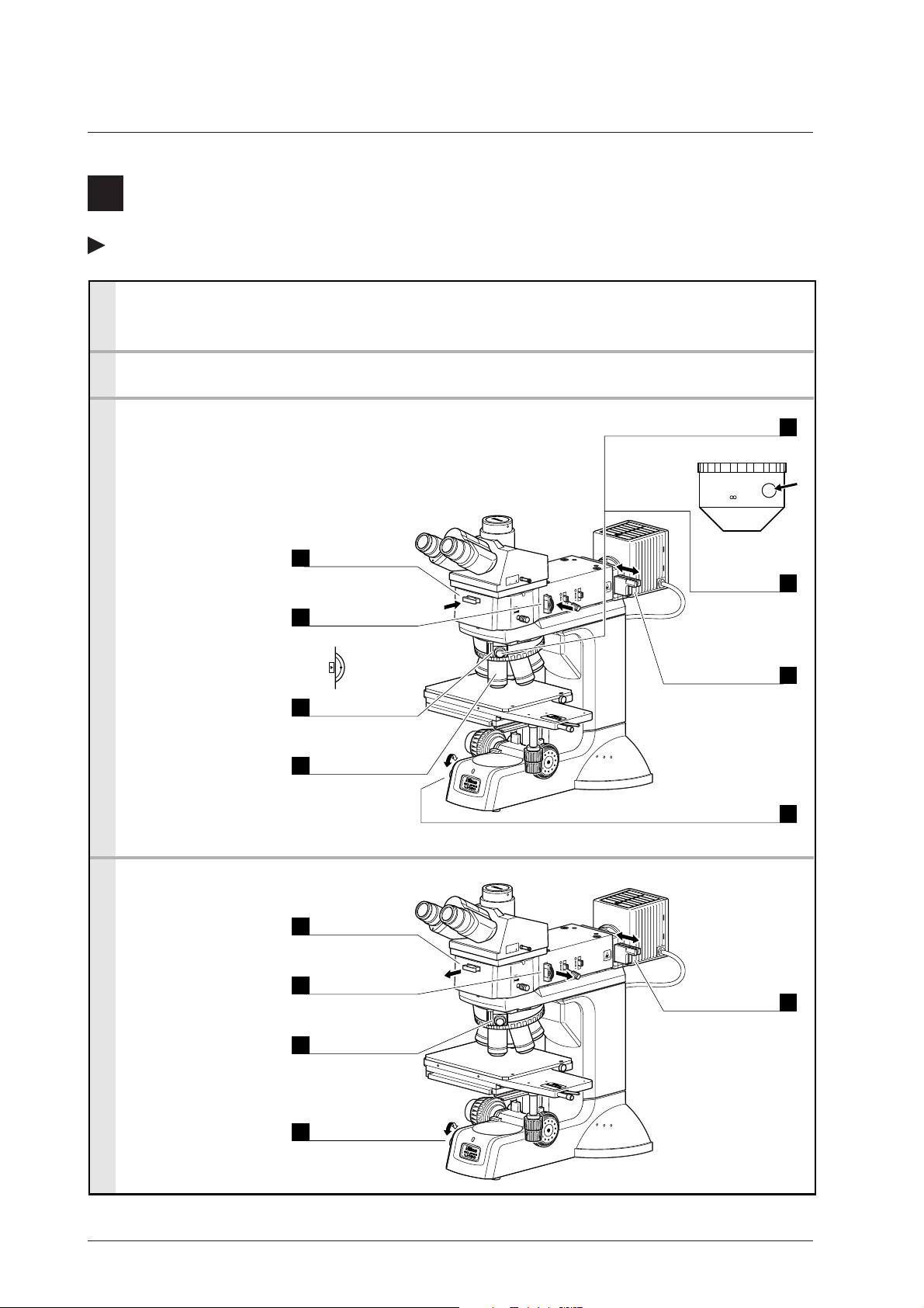
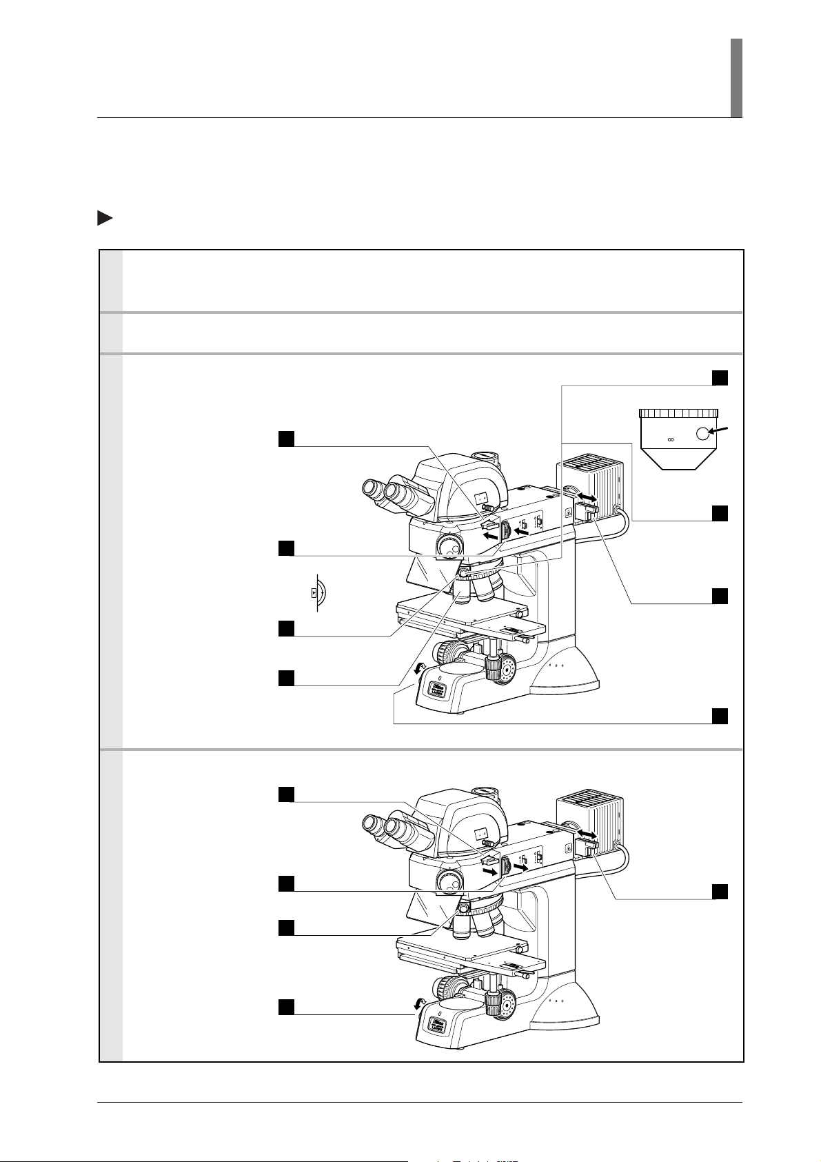
6
Epi-Fluorescence Microscopy
Only when configured with the LV-UEPI2
1. Attach the filter cube to the turret in the illuminator. (p.52)
Up to two filter cubes can be attached.
2. Install the suitable illuminator for the excitation method as necessary. (p.54)
To perform the epi-fl microscopy, the brightness of the specified light source (halogen lamp) may be less than the desired
brightness. An external light source other than the specified ones can be installed for this purpose.
* Please take note that if a light source other than the specified ones are installed onto this microscope, this
microscope system will not be treated as a TUV/SEMI approved product.
3. Find the object using bright-field or dark-field microscopy, and then focus on the sample. (p.17, 19)
4. Set the microscope for epi-fl microscopy.
II. Microscopy
Information:
When the microscopy
selection knob is turned to
the “S” position, the
shutter closes the optical
path of illumination.
To prevent fading of the
Turn the
microscopy
selection knob.
1
FL1 or FL2 (p.33)
sample, be sure to close
the shutter when moving
your eyes away from the
binocular part.
S (for shutter) position
Adjust the
brightness.
S
FL1
FL2
DF
BF
2
Brightness control
knob (p.26)
5. Return the microscope to bright-field microscopy.
Turn the
Information:
During the epi-
fluorescence microscopy,
the UV filter is removed
from the optical path. But
the UV filter is inserted
into the optical path
during the bright-field or
dark-field microscopy.
The inserting/removing of
the UV filter is performed
together with the rotation
of the microscopy
selection knob.
microscopy
selection knob.
1
BF (bright-field) (p.33)
Adjust the
brightness.
4
Brightness control
knob (p.26)
T
U
O
IN
0
0
1
0
20
0
0
1
2
T
-T
V
L
J
A
PA
N
FL1
BF
S
FL2
DF
DF
FL2
S
BF
FL1
STOP
.
A
STOP
.
F
Adjust the
brightness.
3
ND filter (p.26)
6
x
6 ST
JAP
AGE
AN
T
U
O
IN
0
0
1
0
0
2
0
0
1
2
T
-T
V
L
JAP
AN
BF
FL2
DF
S
FL1
STOP
.
A
STOP
.
F
Adjust the
brightness.
3
ND filter (p.26)
6
x
6 STAG
JAPAN
E
25
Page 28

Operation of Each Part
1
Operation of the Illumination
Brightness control
When the specified lamphouse LV-LH50PC is used for the
halogen lamp to illuminate, the brightness can be controlled
by rotating the brightness control knob.
* When an external light source is used, the brightness is
controlled by the external light source or the ND filters
on the microscope.
Turning on/off the lamp
The illumination can be turned on/off by the switch of brightness control knob. The halogen lamp is
turned off when the brightness control knob is rotated to the far side (counter clockwise direction)
and set to the OFF position.
Power indicator
The power indicator color changes according to the halogen lamp status. When the halogen lamp is
lit, it is green. When the brightness control knob is positioned at OFF, it is orange.
2
Filters
OBJ.
Brightness control knob
OFF
Power
indicator
There are two filter sliders in the end of the illuminator. Two filters can be set on each filter slider.
The desired filters can be brought into the optical path by sliding the filter sliders in and out.
For attaching the filters, refer to p.51.
Filters
NCB11 (neutral color balancing filter)
ND4 (ND filter)
ND16 (ND filter)
GIF (green interference filter)
IF (interference filter)
Color balance adjustment and color photomicrography.
Brightness adjustment. (transmittance: 25%)
Brightness adjustment. (transmittance: 6%)
Contrast adjustment.
For interference.
Usage
26
Page 29

III. Operation of Each Part
3
Coarse/Fine Focus Knobs
Relationship between focus knob rotation and stage vertical movement
The relationship between the direction of coarse/fine
focus knob rotation and the stage vertical movement is
shown in the figure.
• The stage moves approximately 14.0 mm per one
full rotation of the coarse focus knob.
• The stage moves 0.1 mm per one full rotation of
the fine focus knob.
• The stage moves 1 µm per one step of the fine
focus knob graduations.
• The stroke (range) of stage vertical movement is
30 mm.
Reference) When observing with the combination of “6x6
inch stage” and “ESD plate”, the stage vertical
movement range is 11.5 mm up and 28.5 mm
down.
T
U
O
IN
0
0
1
0
0
0
0
1
STOP
STOP A
.
F
BF
DF
6
x
6
S
J
A
TA
PAN
G
E
Never attempt either of the following actions, as these will damage the microscope.
• Rotating the left and right knobs in opposite directions at the same time.
• Continuing to rotate the coarse focus knob after the stage has reached the limit of its
motion.
Adjusting the torque of the coarse focus knob
The torque of the coarse focus knob can be adjusted.
To increase the torque, turn the coarse torque
adjustment ring (labeled “TORQUE→”, located at
the root of the coarse focus knob) in the direction
shown by the arrow on the microscope base.
To decrease the torque, turn it opposite to the arrow.
To increase the torque
OBJ.
OFF
Torque adjustment ring
6
x
6 STAGE
JAPAN
27
Page 30

Coarse focus stopper
6
x
6
S
TA
G
E
J
A
P
A
N
The coarse focus stopper restricts the movement of the coarse focus knob so that the stage cannot
be raised higher than the position the operator specifies.
When the coarse focus stopper ring is rotated in the direction of the arrow (labeled “CLAMP→”)
on the microscope base, the coarse focus knob cannot be used to move the stage any higher.
(Movement of the stage by the fine focus knob is not restricted.)
For example, once the coarse focus knob is clamped in place at the focus position, a rough focus
can be attained the next time simply by raising the stage until the coarse focus knob cannot be
turned any further.
If the coarse focus stopper is not being used, be sure to turn the ring in the direction opposite to the
arrow on the microscope base as far as it goes.
[Example usage]
With the sample in focus, turn the coarse focus
stopper ring as far as it goes in the direction of the
arrow (labeled “CLAMP→”) on the microscope
base (about 3/4 revolution). The coarse focus
stopper is now clamped in position.
When changing the sample, lower the stage by
turning only the coarse focus knob.
After changing the sample, gently raise the stage by
turning only the coarse focus knob as far as it goes.
The sample should be roughly in focus when the
stage has been raised as far as it goes. Use the fine
focus knob to bring the sample into perfect focus.
Coarse focus
stopper ring
Clamp
28
Page 31

4
Eyepiece Tube
Optical path selection
The optical path selection lever can be used to switch between the proportions of light reaching the
binocular part and the vertical tube.
III. Operation of Each Part
Lever
position
Light proportion
Binocular part Vertical tube
100IN 0
0OUT 100
IN OUT
100
0
100 0
Lever
position
Light proportion
Binocular part Vertical tube
100IN 0
20OUT 80
T
OU
IN
100
0
100 20
LV-TT2
Eyepiece tube LV-TI3 Eyepiece tube LV-TT2
Vertical tube adapters
When attaching photomicrographic equipment or TV camera to the vertical tube of the trinocular
eyepiece tube, you must first mount the adapter (photomicrographic vertical tube adapter or direct
C-mount adapter; both sold separately). Insert the adapter into the vertical tube and secure it with
the clamp screw using a hexagonal screwdriver.
Vertical tube adapter
Cap
Clamp screw
Vertical tube adapter
Cap
Clamp screw
IN OUT
100
0
0
100
Eyepiece tube LV-TI3 Eyepiece tube LV-TT2
Angular adjustment of binocular part (for the LV-TT2 only)
With the trinocular eyepiece tube LV-TT2, the angle of
the binocular part can be adjusted. Adjust it to an easily
viewable angle.
Centering the binocular part (for the LV-TT2 only)
The binocular part and the vertical tube part of the eyepiece
tube are centered before the shipping, so usually they can be
used with no adjustment.
But some cameras are not aligned their centers of the CCD
to the mount. You can center the vertical part by adjusting
two centering screws on the back of the vertical tube for
such cameras.
OUT
IN
100
0
100 20
LV-TT2
IN OUT
0100
100 20
LV-TT2
Centering screws
IN OUT
0 100
100 20
LV-TT2
(two locations)
29
Page 32

5
Diopter Adjustment
Diopter adjustment compensates for differences in eyesight between your left and right eyes. After
the correct adjustment, you will find the observation with both eyes easier and the focus shift is
reduced when switched to different objectives. Be sure to adjust the diopter adjustment rings on
both eyepieces.
1 Turn the diopter adjustment rings on both eyepieces to align their engraved lines with the
edge of the outer tube of the eyepiece. (This is the standard position for diopter adjustment.)
2 Focus on the sample with the 10x objective following the steps of bright-field microscopy
(p.16, 17).
3 Bring the 50x objective into the optical path and focus on the sample by turning the coarse/
fine focus knobs.
4 Bring the 5x or 10x objective into the optical path.
5 Focus on the sample by turning the diopter adjustment ring on the right eyepiece (not the
coarse/fine focus knobs).
Look through the left eyepiece with your left eye, and the right eyepiece with your right eye,
to focus on the sample with the diopter adjustment rings.
6 Repeat steps 3 to 5 with the 50x and 5x (or 10x) objectives until the image stays in focus
even though the objective magnification is changed.
Diopter
adjustment
ring
Outer tube
edge
Engraved
line
T
U
O
IN
0
0
1
0
0
0
0
1
BF
DF
STOP
.
A
STOP
.
F
Positioning
grooves
Diopter adjustment standard position
6
Interpupillary Distance Adjustment
Before adjusting the interpupillary distance,
perform the steps of bright-field microscopy (p.16,
17) and focus on the image with the 10x objective.
Adjust the interpupillary distance so that the
viewfields for both eyes are at the same position on
the sample.
Doing so will make observation through the
binocular eyepieces with both eyes easier.
The scale on the binocular part is useful in order to
memorize your interpupillary distance for the next
time.
T
U
O
IN
100
0
0
0
10
BF
DF
STOP
.
STOP A
.
F
Merge the view fields into one.
30
Page 33

7
Field Diaphragm
III. Operation of Each Part
The field diaphragm open/close lever changes the size of the field
diaphragm. Adjust the size of the diaphragm until it circumscribes or
inscribes the viewfield.
About the field diaphragm
• The field diaphragm restricts illumination on the sample to the
area being observed.
• Illuminating an area larger than necessary can let in stray light,
creating flaring and reducing the contrast of the optical image.
• Proper operation of the field diaphragm is important during photomicrography. Generally, the
field diaphragm should be set to the area to be exposed on film, that is, to an area slightly
larger than the photographed area.
• Be sure to adjust the field diaphragm after centering it.
Eyepiece view field
Centering the field diaphragm
1 Focus on the sample with the 10x objective by following the steps of bright-field microscopy
(p.16, 17).
2 Lower the field diaphragm open/close lever to reduce the field diaphragm opening.
3 Turn the two field diaphragm centering screws on both sides to move the center of the field
diaphragm image to the center of the viewfield.
If the illuminator LV-UEPI2 is used, insert a hexagonal wrench into the field diaphragm
centering holes on both sides and turn the internal adjustment screws.
4 Use the field diaphragm open/close lever and centering screws so that the field diaphragm
image is inscribed in the viewfield.
5 When starting observation, raise the field diaphragm open/close lever so that the field
diaphragm image is slightly larger the viewfield.
Image of field
diaphragm
Image of field diaphragm
Eyepiece view field
31
Page 34

8
Aperture Diaphragm
Remove one of the eyepieces. Operating the aperture diaphragm
Objective’s exit pupil
open/close lever will change the size of the aperture diaphragm
as seen within the objective's exit pupil in the eyepiece tube.
Generally, the aperture diaphragm should be adjusted to about 70 to
80% of the numerical aperture of the objective.
70 to 80
100
Aperture diaphragm
About the aperture diaphragm
• Since the aperture diaphragm is for adjusting the numerical aperture of the illumination
system, this diaphragm is related to the resolution, contrast, and depth of focus of the optical
image.
• The diaphragm image may not appear in the case of samples with low reflectivity. In this case,
change to a sample with a near-polished surface.
• For the illuminator LV-UEPI, the aperture diaphragm centering has been adjusted at the
factory and does not need to be adjusted.
Centering the aperture diaphragm (for the LV-UEPI2 only)
When the illuminator LV-UEPI2 is used, the aperture diaphragm centering can be adjusted through
these steps:
1 Focus on the sample with the 10x objective by following the steps of bright-field microscopy
(p.16, 17).
2 Remove one of the eyepieces. Check that the aperture diaphragm image is seen within the
objective’s exit pupil in the eyepiece tube.
3 Lower the aperture diaphragm open/close lever to reduce the field diaphragm opening.
4 Insert a hexagonal wrench into the aperture diaphragm centering holes on both sides and turn
the internal adjustment screws to bring the aperture diaphragm image to the center of the
objective's exit pupil.
5 Use the diaphragm open/close lever and centering screws so that the aperture diaphragm
image is inscribed in the objective’s exit pupil.
6 When starting observation, adjust the aperture diaphragm open/close lever so that the
aperture diaphragm image is 70 to 80% of the numerical aperture of the objective. (Adjust the
aperture diaphragm for each objective.)
32
Image of aperture diaphragm
Objective’s exit pupil
Page 35

III. Operation of Each Part
9
Illumination Selection Lever and Microcopy Selection Knob
1. Illumination selection lever (for the LV-UEPI)
When the illuminator LV-UEPI is used, the illumination
selection lever on the right side can be used to alternate the
microscopy illumination between bright-field (BF) and darkfield (DF).
IN
0
00 0
1
Push the lever in to select bright-field illumination (BF), or
pull it out to select dark-field illumination (DF).
Illumination selection lever
2. Microscopy selection knob (for the LV-UEPI2)
When the illuminator LV-UEPI2 is used, the microscopy
selection knob at the front right of the illuminator can be
turned to rotate the turret in the illuminator to the position of
the desired microscopy mode.
The microscopy selection knob has five clickstop positions,
BF, DF, FL1, S, and FL2, which correspond to the
microscopy modes listed below.
Microscopy selection knob
BF
FL2
DF
S
FL1
T
U
O
0
0
1
BF
DF
STOP
.
A
STOP
.
F
T
U
O
IN
00
1
0
0
2
00
1
2
T
T
VL
J
A
PA
N
STOP
.
A
STOP
.
F
Position
BF
Bright-field microscopy
Microscopy
This is used for the usual bright-field microscopy. It is used also for differential
interference contrast (DIC) microscopy and simplified/sensitive polarization microscopies.
The UV filter enters into the optical path when the BF position is selected.
DF
Dark-field microscopy
Setting the knob to DF selects the dark-field illumination, so that the aperture diaphragm
and field diaphragm automatically open fully. The positions of the diaphragm levers do not
change. When the knob is set to a position away from DF, the aperture diaphragm and field
diaphragm are restored to what they were before setting to DF.
The UV filter enters into the optical path when the DF position is selected.
FL1
Epi-fluorescence 1
The filter cube inserted into the “FL1” position in the illuminator enters the optical path.
And, the UV filter is removed from the optical path.
S
Shutter
The shutter stops the optical path of illumination. This clickstop position is between FL1
and FL2, so that the shutter is readily available to prevent fading of the sample.
FL2
Epi-fluorescence 2
The filter cube inserted into the “FL2” position in the illuminator enters the optical path.
And, the UV filter is removed from the optical path.
If no filter cube is set on the turret in the illuminator, nothing is seen when the knob is turned to the
FL1 or FL2 position.
33
Page 36

10
Stage
1. 6x6 stage
The stage can be moved in either the “coarse” mode for swift and long ranged movement, or the
“fine” mode for minute movement. To switch between the modes, use the stage coarse/fine
movement selection switch on the right side of the stage’s top plate.
The “coarse” mode
Hold both the stage coarse/fine movement selection
switch and the stage coarse movement lever. The stage
is now in the “coarse” mode, so that it is freely
movable in both X and Y directions. Take hold of the
switch and the lever when moving the stage.
Moving the stage only with the stage coarse
movement lever without holding the coarse/fine
movement selection switch will damage the stage.
Likewise, pushing or pulling the stage plate without
using the switch and the lever will damage the stage.
Make sure that the coarse/fine movement selection
switch is held for the coarse mode.
Coarse/fine movement
selection switch
6x6 STAGE
JAPAN
JAPAN
Coarse movement lever
Hold both of
the switch
and the lever.
The “fine” mode
Release the stage coarse/fine movement selection
switch. The stage is now in the “fine” mode. Turn the
stage fine movement knobs to move the stage
minutely in both X and Y directions.
Fine movement knob
for the Y-axis
Fine movement knob
for the X-axis
2. 3x2 stage
Stage movement
To move the stage, turn the stage fine movement
knobs for the X-axis and Y-axis.
Upper knob is for the Y-axis and lower knob is for the
X-axis. Use these knobs to move the specimen
minutely.
* If you move the stage plate directly, the stage will
Fine movement knob
for the Y-axis
Fine movement knob
for the X-axis
be damaged. Use these fine movement knobs to
move the stage.
Slide glass usage
To observe a specimen by using a slide glass, replace the stage glass to the optional slide glass
holder.
Loosen the clamp screw on the left side of the stage to remove the standard stage glass. Then,
mount the slide glass holder and secure it by the clamp screw.
34
Page 37

11
Motorized Nosepiece Operation
The LV150A is equipped with a motorized nosepiece, and
you can rotate the nosepiece by operating the nosepiece
rotation buttons on the left side of the microscope to
change objectives.
Two buttons, far side and near side, are used as the
nosepiece rotation buttons. The nosepiece is rotated each
time when either button is pressed.
When the far side button is pressed, the nosepiece is
rotated in the clockwise direction viewed from the top.
And the near side button is pressed, the nosepiece is
rotated in the counterclockwise direction viewed from the
top.
III. Operation of Each Part
OBJ.
Clockwise Counterclockwise
Nosepiece rotation buttons
OFF
OBJ.
Be careful about the following items to use the motorized nosepiece:
• To mount objectives onto the motorized nosepiece, magnifications of objectives are placed
in ascending order from No. 1 position of the nosepiece.
• The nosepiece rotation from No. 1 position to No. 5 position and from No. 5 position to
No. 1 position is prohibited in normal operation.
This limit is applied because a collision may occur when a rotation from the lowest
magnification objective to the highest magnification objective is attempted under an
inadequate adjustment.
If you wish to rotate the nosepiece between No. 1 position and No. 5 position on purpose,
press the button for the opposite direction while holding down the desired direction
button. Before this operation, be sure to adjust each part of the microscope and check that
no collision occurs for objectives.
35
Page 38

12
Polarizer Slider
The polarizer slider can be used together with the
analyzer slider to enable the simplified polarization
First clickstop position
Second clickstop position
microscopy. Likewise, the polarizer slider can be
combined with the analyzer slider and DIC slider to
Polarizer rotating ring
perform DIC microscopy, and with the analyzer slider
and lambda plate slider to perform sensitive
polarization microscopy (with the LV-UEPI2 only).
Polarizer
JAPAN
Placing the polarizer in the optical path
• For the LV-UEPI:
Remove the dummy slider at the right side of the illuminator, and in its place, insert the polarizer
slider with its orientation indication facing toward the eyepieces. (p.51)
• For the LV-UEPI2:
Remove the vertically oriented cover at the right side of the illuminator. Insert the polarizer slider
into the rear slot with its orientation indication facing toward the eyepieces. In the front slot, insert a
dummy slider or lambda plate slider. (p.51)
• Insertion to the optical path:
Pushing the polarizer slider in to the first clickstop position inserts the empty hole into the optical
path. Pushing it further in to the second clickstop position inserts the polarizer into the optical path.
Set the orientation of the polarizer by turning the polarizer rotating ring.
Removing the polarizer out of the optical path
With the polarizer placed in the optical path, pull it out in the right direction to the first clickstop
position. The polarizer has been removed out of the optical path (instead, the empty hole is now in
the optical path).
Adjusting the orientation of the polarizer
Turning the polarizer rotating ring changes the
orientation of the polarizer. Here is how to bring the
polarizer and the analyzer into the crossed Nicols
position.
Place the polarizer and the analyzer in the optical
path. Place a specimen with a flat and plain surface
on the stage and set the microscope for simplified
polarization microscopy.
Remove one eyepiece from the microscope and look
inside the open sleeve. You can see the objective’s
pupil as a bright circle.
Turn the polarizer rotating ring in either direction
until the dark cross appears in the viewfield. This is
the crossed Nicols position.
(Matching the marks on the polarizer rotation dial as
shown in 1 on the illustration will bring about the
crossed Nicols position as well.)
Polarizer orientation
2
T
U
O
IN
0
0
1
0
0
0
0
1
BF
DF
STOP
.
STOP A
.
F
1
Lateral
1
direction
Vertical
2
direction
36
Dark cross
Page 39

UV polarizer slider
The UV polarizer slider is used for the epi-microscopy under the UV excitation light to make the
excitation light to the linear polarization. The UV polarizer will deteriorate over time, so change it
as necessary.
13
Lambda Plate Slider (for the LV-UEPI2 only)
III. Operation of Each Part
If the LV-UEPI2 is used for the illumination, the lambda
plate slider can be used together with the polarizer slider
First clickstop position
Second clickstop position
and analyzer slider to perform sensitive polarization
microscopy.
Lambda plate
(wavelength plate)
Placing the lambda plate in the optical path
Remove the dummy slider found in front of the polarizer slider, and in its place, insert the lambda
plate slider. (p.51)
Pushing the lambda plate slider in to the first clickstop position inserts the empty hole into the
optical path. Pushing it further in to the second clickstop position inserts the lambda plate into the
optical path.
Removing the lambda plate out of the optical path
With the lambda plate placed in the optical path, pull it out in the right direction to the first
clickstop position. The lambda plate is now out of the optical path.
IN
OUT
37
Page 40

14
Analyzer Slider
The analyzer slider can be used together with the polarizer
slider to enable simplified polarization microscopy.
First clickstop position
Second clickstop position
Likewise, the analyzer slider can be combined with the
polarizer slider and DIC slider to perform DIC microscopy,
and with the polarizer slider and lambda plate slider to
perform sensitive polarization microscopy (with the LVUEPI2 only).
Analyzer
Placing the polarizer in the optical path
• For the LV-UEPI:
Remove the dummy slider at the front of the illuminator, and in its place, insert the analyzer slider
with its marking facing up. (p.51)
• For the LV-UEPI2:
Remove the horizontally oriented cover at the right side of the illuminator. Insert the analyzer slider
into the horizontal slot with its marking facing up. (p.51)
• Insertion to the optical path:
Pushing the analyzer slider in to the first clickstop position inserts the empty hole into the optical
path. Pushing it further in to the second clickstop position inserts the analyzer into the optical path.
* The orientation of the analyzer is as indicated by the arrow on the slider.
For the LV-UEPI For the LV-UEPI2
UT
O
IN
100
0
20
100
TT2
LV-
J
A
P
A
N
BF
FL2
DF
S
FL1
STOP
.
A
STOP
.
F
Analyzer slider
Analyzer slider
UT
O
IN
100
0
0
100
BF
DF
STOP
.
STOP A
.
F
Analyzer orientation
Removing the polarizer out of the optical path
With the analyzer placed in the optical path, pull it out toward you to the first clickstop position.
The analyzer has been removed out of the optical path (instead, the empty hole is now in the optical
path).
38
Page 41

15
DIC Slider
III. Operation of Each Part
For DIC microscopy, use the DIC slider together with
the polarizer and analyzer sliders.
Sliding limit groove
Prism selection knob
Prism movement knob
L-DIC
JAPAN
61108
A
B
Attaching/removing the DIC slider
Use a hexagonal screwdriver to loosen the DIC slider
limit screw on the nosepiece.
Insert the DIC slider into the slot on the nosepiece
and screw in the DIC slider limit screw.
When removing the DIC slider from the nosepiece,
fully loosen the DIC slider limit screw using a
hexagon screwdriver, and then pull out the slider.
DIC slider limit screw
Placing the DIC prism in the optical path
Push in the slider to the second clickstop position to place the DIC prism in the optical path.
Removing the DIC prism out of the optical path
Pull out the slider to the first clickstop position to remove the DIC prism out of the optical path.
Selecting the DIC prism position
The correct position of the prism selection knob is indicated on the
objective barrel after the magnification and the objective N.A. indications.
In the objective shown in the figure on the right, the letter “A” on the
objective indicates that the correct DIC prism position for this objective is
“A”. Thus, when you use this objective, turn the prism selection knob on
the DIC slider to match the letter “A” with the white circle.
Selecting an interference color
Turn the prism movement knob to change the interference colors continuously.
Interference color
Dark
Gray
Sensitive red-violet
Observation similar to dark-field microscopy can be performed.
This color enables observation of the phase difference distribution for the
whole sample.
Observation with the highest color contrast can be performed.
Characteristics
CF Plan
10X/
/0 BD DIC
0.30
A
39
Page 42

16
Filter Cubes for Fluorescence Observation (for the LV-UEPI2 only)
The illuminator LV-UEPI2 accommodates two filter cubes for
Barrier filter
epi-fluorescence observation.
The filter cube consists of an excitation (EX) filter, barrier (BA)
filter, and dichroic mirror (DM). Note the following
UV-2A
EX 330-380
DM 400
BA 420
considerations as a guideline and choose the right combination of
filters that are most suitable for the characteristics of the sample
and fluorescent stain.
• Different combinations of excitation filter and barrier filter are
available for the same excitation method.
• Excitation filters, barrier filters, and dichroic mirrors can be
Excitation filter
Dichroic mirror
(housed inside)
purchased separately.
• Excitation filters will deteriorate over time since they are exposed to intense light. Replace them
as necessary.
Light source for the epi-fl microscopy
To perform the epi-fl microscopy with the LV-UEPI2 illuminator, the specified light
source brightness may be less than the desired brightness. An external light source
suitable for the excitation method can be installed into the LV-UEPI2 for this purpose.
* Please take note that if a light source other than the specified ones are installed onto
this microscope, this microscope system will not be treated as a TUV/SEMI approved
product. Nikon recommends that the light source to be installed onto this microscope
should have been tested by a safety certification organization.
Selecting an excitation (EX) filter
The excitation filter selectively transmits only the light of the
wavelength range required for the sample to fluoresce, while
blocking the other light. The wavelength range of light that
can pass through the filter is called the bandwidth. The
bandwidth of an excitation filter determines the brightness of
Spectral
fluorescence image, the occurrence of self-fluorescence
(fluorescence generated by materials other than the fluorescent
stain), and the degree of fading. A wider bandwidth delivers more excitation light to the sample and
makes the image brighter, but it induces more self-fluorescence and therefore more fading A
narrower bandwidth delivers less excitation light to the sample and makes the image darker, but it
induces less self-fluorescence and therefore less fading. If self-fluorescence is too intense, use an
excitation filter of narrower bandwidth. (The fluorescence image becomes darker, however.)
Excitation filters will deteriorate over time since they are subject to intense light. Replace them as
necessary depending on their total operating hours.
Narrow Bandwidth of excitation filter Wide
Brightness of fluorescence image
Occurrence of self-fluorescence
Degree of fading
Dark Bright
Less frequent Frequent
Small Large
EX filer
transmittance
0
Bandwidth
Wavelength
40
Page 43

III. Operation of Each Part
Selecting a barrier (BA) filter
The barrier filter transmits only the fluorescence emitted by the sample, blocking the excitation
light. This enables observation of fluorescence images having less unnecessary light (darker
background).
BA filters are available in two types: long-pass (LP) and band-pass (BP). The LP filter blocks all
the light of shorter wavelength than a given value. The BP filter transmits light in a given
wavelength range. Use the suitable types in accordance with your purposes.
• Long-pass (LP) filter
The LP filter blocks all the light of shorter wavelength
than a given value, called the cut-on wavelength.
1) Some sample may be stained with a fluorescent color
for which the fluorescence waveband and the
excitation waveband (the light that the sample absorbs
to emit fluorescence) are very close to each other.
Spectral
Then, fluorescence microscopy generally will be more
transmittance
efficient by selecting a filter for which the cut-on
wavelength is as short as feasible.
A longer cut-on wavelength tends to result in a more
Both fluorescence images due to FITC
and TRITC are seen
complete separation between excitation light and
fluorescent light, rendering a darker background of the fluorescence image. With the recent
advancement in filter performance, however, shorter cut-on wavelengths are used more often
than before.
2) LP filters are used for samples stained in multiple colors where fluorescence images for all the
colors are desired.
However, the usual combination of a dichroic mirror, an excitation mirror, and a barrier filter of
LP filter type, may not be sufficient to excite a stain that emits fluorescence of longer
wavelength (for example, TRIC when the sample is stained with FITC and TRITC), making the
fluorescence image for TRITC very dark. In a case like this, a multi-band filter is recommended.
Fluorescence
waveband for FITC
LP520
Wavelength
Fluorescence
waveband
for TRITC
• Band-pass (BP) filter
The BP filter transmits light of a certain wavelength range.
This type of filter is used for samples stained in multiple
colors where fluorescence images due to a certain stain are
desired. (For example, in the case of a dual-stained sample,
say FITC and TRITC, and fluorescence images due only to
FITC are desired, then BA520-560 should be selected.)
If a BP filter is used, however, any self-fluorescence
cannot be discriminate (because the fluorescence image
will be green all over for the above combination).
The LP filter is more useful when you wish to discriminate
self-fluorescence by a subtle difference in hue.
Fluorescence
waveband for FITC
BA520-560
(BP type)
Fluorescence
Spectral
transmittance
Only fluorescence image due to
FITC is seen
waveband
for TRITC
Wavelength
41
Page 44

Replacing the excitation filter, barrier filter, and dichroic mirror
The excitation filter, barrier filter, and dichroic mirror can be removed from the filter cube and
replaced with different parts.
When handling these parts, put on gloves and do not touch the surface of filters and mirrors with
bare hands. And be careful not to let dust or fingerprints get on them.
• Replacing the excitation filter
The excitation filter is secured by a screwed type holding ring to the filter cube.
1 Rotate the holding ring in counterclockwise direction
to remove it.
Holding ring
2 Replace the excitation filter and secure it by the
holding ring.
Check and see the arrow mark on the rim of the
excitation filter is directed to the dichroic mirror side
when attaching the excitation filter.
If a filter made by other manufacturer is used, check
(The arrow indicates the mirror.)
Excitation filter
and see the indication on the rim of the filter.
• Replacing the barrier filter
The barrier filter is secured by a screw type holding ring to the mounting plate on the upper side of
the filter cube.
1 Press the latch to inside and detach the mounting plate
and barrier filter together.
2 Rotate the holding ring to remove it from the
mounting plate.
3 Replace the barrier filter and secure it in reverse order.
Holding ring
Barrier filter
(The arrow
points down
(mirror).)
Mounting plate
Check and see the arrow mark on the rim of the barrier
filter is directed to downward (dichroic mirror side)
when attaching the barrier filter.
If a filter made by other manufacturer is used, check
and see the indication on the rim of the filter.
UV-2A
EX 330-380
DM 400
BA 420
UV-2A
EX 330-380
DM 400
BA 420
Latch
• Replacing the dichroic mirror
The dichroic mirror is fixed with a flat spring and a mounting part inside the filter cube.
1 Detach the mounting plate and barrier filter together.
2 Pull the mounting part upward to remove it. (It is
Barrier filter and
mounting plate
clamped with latches on both sides.)
3 Remove the flat spring and dichroic mirror.
Mounting part
4 Replace the dichroic mirror and put it back to the
original position with the flat spring.
Flat spring
One side of the edge of the dichroic mirror is slanted
to distinguish the reflection surface. The slanted edge
Dichroic mirror
is placed to downward to fit the bottom surface of the
dichroic mirror.
Flat spring
Mirror
And the flat spring is placed to hold the both side of
the dichroic mirror.
5 Put the mounting part and barrier filter back to their
original positions.
The slanted side is
placed downward.
UV-2A
EX 330-380
DM 400
BA 420
42
Page 45

17
Excitation Light Balancer (for the LV-UEPI2 Only)
When the illuminator LV-UEPI2 is used, the optional DFB excitation light balancer can be attached for the epi-fl
microscopy to observe specimens stained in multiple
colors.
The excitation light balancer enables the continuous
change of the wavelength characteristics for the
excitation light without replacing filter cubes.
The excitation light balancer is used in concert with a
dual-band characteristic filter cube.
III. Operation of Each Part
D-FB
Excitation light balancer
Excitation light balancer usage
Remove the vertically oriented cover on the left side of
the illuminator, and insert the excitation light balancer
with its indication faces back.
When the excitation light balancer is inserted to the limit
position, it enters into the optical path. You can adjust the
excitation light by sliding the excitation light balancer
horizontally.
Objectives
To use the excitation light balancer, use the following
objectives in combination. If other objective is used,
uneven image may be observed in the view field.
Plan Fluor
S Fluor
Plan Apo
40x/0.75
40x/0.9
40x/0.95
40xH/1.3
40xH/1.3
60xH/1.3
100xH/1.3
100xH/1.3
100xH/1.4
Excitation light
balancer
N
A
P
A
J
43
Page 46

Detailed specification of excitation light balancer
III. Operation of Each Part
(1)
A
Tr ansmittance
100%
50%
0%
350 400 450 500 550 600
(2) (3)
A
B
DAPI
B
A
FITC
B
TRITC
Te xas-Red
: Effective diameter
on the aperture
diaphragm surface
Wavelength
650 700
The transmittance for the FITC is designed to keep approximately 100%, because the FITC is
usually dark fluorescent image.
Optical path position
(1)
Between (1) and (2)
(2)
Between (2) and (3)
(3)
DAPI
100%
Variable (100% to 50%)
50%
Variable (50% to 0%)
0%
FITC
100%
100%
100%
100%
100%
TRITC / Texas-Red
0%
Variable (0% to 50%)
50%
Variable (50% to 100%)
100%
44
Page 47

Assembly
Assemble each part of the microscope by referring to the diagram on the next page.
WARNING
CAUTION
• Before assembling the microscope, be sure to read the WARNING and CAUTION
at the beginning of this instruction manual and follow the instructions written therein.
• To prevent electrical shocks and fire, turn off the power switch (flip it to the “ ” side)
when assembling the microscope.
• Be careful not to pinch your fingers or hands during assembly.
• Scratches or fingerprints on the lens surface will adversely affect the microscope
image. Be careful not to scratch or touch the lens surfaces. If lenses are contaminated
with fingerprint or such, clean them according to the procedure described in “VII.
Care and Maintenance.”
• The microscope is a precision optical instrument. Handle it carefully and do not
subject it to a strong physical shock. (In particular, objectives may loose accuracy
when exposed to even a weak physical shock.)
Required tools
• Hexagonal screwdriver 2 mm × 2 (supplied with the microscope)
• Hexagonal wrench 3 mm × 1 (supplied with the microscope)
When not using, place these in the tool holder at the right side of the microscope base.
Installation location
Being a precision optical instrument, this product may get damaged or loose accuracy if it is used or
stored under unsuitable conditions. When selecting the installation location, note the following:
• Avoid a brightly lit location, such as exposed to direct sunlight or directly under a room light.
The image quality deteriorates if there is excessive ambient light.
• Choose a location that is free from considerable dust or dirt.
• Choose a flat surface with little vibration.
• Choose a sturdy desk or table that is able to bear the weight of the instrument.
• Do not install the microscope in a hot or humid location.
• Take enough space around the microscope referring to the layout diagrams on page 6.
• The microscope may be moved by earthquakes. We recommend taking anti-earthquake
measures.
For details about anti-earthquake measures, see “15. Countermeasures for Earthquakes.”
• For details about the operating environment and storage environment, see “VIII.
Specifications.”
Combination of the illuminator and the light source
This microscope system is approved by TUV and SEMI only in the combination of the illuminator
and the light source describe below. Please take note that if a light source other than the specified
ones are installed onto this microscope, this microscope system will not be treated as a TUV/SEMI
approved product.
• Illuminator Nikon LV-LH50PC precentered lamphouse 12V 50W
• Lamphouse Nikon LV-LH50PC precentered lamphouse 12V 50W
• Lamp Nikon LV-HL50W 12V 50W LONGLIFE halogen lamp or non-Nikon 12V
50W SHORTLIFE halogen lamp (model OSRAM HLX 64610, OSRAM HLX
64611, or PHILIPS 7027)
45
Page 48

Assembling the ECLIPSE LV150/LV150A
• When using the illuminator LV-UEPI
LV-TI3
eyepiece tube
Microscope main body
Dummy slider
BD quintuple
nosepiece
Universal
quintuple
nosepiece
BD objective Epi objective
Holder Holder
6x6
stage
(for stages
by other
manufacturer)
SubstageSubstage 2
Eyepiece
or
Analyzer
slider
Standard
sextuple
nosepiece
3x2
stage
• When using the illuminator LV-UEPI2
Dummy
Analyzer slider
LV-UEPI illuminator
LV150/LV150A
slider
or
Filter sliders
(x2)
Lamphouse
Lamp
cable
Power cord
Var ious filters
12V 50W
halogen lamp
Eyepiece
Analyzer slider
Filter cube
(Two cubes max.)
(attached with the fiber adapter)
Compensation filter
BD quintuple
nosepiece
Universal
quintuple
nosepiece
BD objective Epi objective
Holder Holder
6x6
stage
(for stages
by other
manufacturer)
SubstageSubstage 2
Standard
sextuple
nosepiece
3x2
stage
LV-TT2
eyepiece tube
LV-UEPI2 illuminator
LV150/LV150A
Microscope main body
* It is installed if the brightness of the specified light source is
less than the desired brightness for the episcopic microscopy
or so on. (Please take note that if a light source other than the
specified ones are installed onto this microscope, this
microscope system will not be treated as a TUV/SEMI
approved product.)
Dummy
slider
or
lambda plate slider
or
Polarizer
slider
Filter slider (x2)
Fiber
adapter *
Lamphouse
Lamp
cable
Power cord
Light guide
fiber *
Var ious filters
Light source *
12V 50W
halogen lamp
46
Page 49

1
Attaching the Stage and the Holder
1. Attaching the sub-stage
The sub-stage must be attached onto the microscope before installing the stage.
1 Lower the sub-stage completely with the coarse focus
knob.
2 Loosen the clamp screw for the sub-stage. And then
attach the sub-stage with fitting the dovetail joints on
the up/down part. Secure the sub-stage by the clamp
screw so that the upper surfaces of the up/down part
and sub-stage are the same height.
3 If you wish, the sub-stage can be attached at the 8 mm
below from the standard position described above.
Adjust it according to the specimen.
2. Attaching the Sub-stage 2
IV. Assembly
Sub-stage
Up/down part
A 60 mm square stage made by other manufacturer can be
50 mm
attached by using the sub-stage 2.
The tap dimensions for the sub-stage 2 are described in the
figure on the right.
1 Lower the sub-stage completely with the coarse focus
50 mm
knob.
2 Loosen the clamp screw for the sub-stage 2. And then
attach the sub-stage 2 with fitting the dovetail joints on
the up/down part. Secure the sub-stage 2 by the clamp
screw so that the upper surfaces of the up/down part and
Tap dimensions for the sub-stage 2
sub-stage 2 are the same height.
3 If you wish, the sub-stage can be attached at the 16 mm below from the standard position
described above. And more, when the sub-stage is attached upside down, the stage surface
can be lowered 26.5 mm below from the standard height.
Sub-stage 2 Sub-stage 2
After attaching the sub-stage Upside down condition
8-M4
47
Page 50

3. Attaching the Stage and the Holder
6x6 stage
1 Lower the sub-stage completely with the coarse focus knob.
2 Remove the fixing metals from the stage plate by using the 3-mm hexagonal wrench to the
four hex screws.
3 Place the stage on the substage and fix it with the four M4 screws that were attached to the
sub-stage.
4 Place the holder onto the stage by matching its two positioning holes with the two pins on the
stage. Secure the holder with the clamp screw at the right side of the stage top plate. Take
care not to lift up the holder by tightening the clamp screw too much.
3x2 stage
1 Lower the sub-stage completely with the coarse focus knob.
2 Place the sub-stage and secure it with the four M4 screws provided with the sub-stage, using
the 3-mm hexagonal wrench.
3 Loosen sufficiently the stage clamp screw. Place the holder on top of the stage and fit it in
position so that it is level. Tighten the clamp screws.
Take care not to lift up the holder by tightening the clamp screw too much.
2
Assembling the Nosepiece
1. Assembling the manual nosepiece
1 Fully loosen the nosepiece clamp screw on the right side of the microscope arm using the
hexagonal screwdriver.
2 Fit the nosepiece from the front by aligning it to the groove in the bottom of the microscope
arm and push it all the way.
3 Secure the nosepiece by tightening its clamp screw.
48
Page 51

IV. Assembly
2. Assembling the motorized nosepiece
For the LV150A, the motorized nosepiece must be attached.
The motorized nosepiece should be assembled before attaching the illuminator.
1 Remove the cover from the connection block by unscrewing the two M4 screws on the top of
the microscope arm.
2 Loosen sufficiently the nosepiece clamp screw on the right side of the microscope arm using
the hexagonal screwdriver.
3 Fit the nosepiece from the front by aligning it to the groove in the bottom of the microscope
arm and push it all the way.
Pass the signal cable of the nosepiece through the bottom hole of the arm into the microscope.
4 Secure the nosepiece by tightening its clamp screw.
5 Connect the signal cable of the nosepiece to the cable in the arm.
6 Close the cover over the connection block and secure it with the two M4 screws.
6
5
3
Nosepiece clamp
screw
214
3. Removing the nosepiece
Removing the nosepiece is the reverse order of the above procedure. When removing the nosepiece,
lower the stage completely, remove the sample and all objectives, and hold the nosepiece in your
hand so that it does not fall when you remove it.
49
Page 52

3
Attaching the Illuminator
1. Illuminator main unit
1 Loosen sufficiently the illuminator clamp screw on the front of the microscope arm using the
hexagonal screwdriver.
2 Mount the illuminator onto the microscope arm and fix it by tightening the illuminator clamp
screw.
3 Secure the illuminator on the microscope arm. Do this by tightening the hex screws supplied
with the illuminator (four screws for LV-UEPI, or two screws for LV-UEPI2) using the
hexagonal wrench.
4 Cover the bolt holes with the protective stickers supplied with the illuminator.
5 For the LV-UEPI2, attach the ultraviolet light shield to the front bottom of the illuminator
using the two screws supplied.
For the LV-UEPI
Hex screws (x4)
STOP
.
STOP A
.
F
BF
DF
Illuminator
clamp screw
For the LV-UEPI2
Ultraviolet light shield
(To be secured
Hex screws (x2)
J
A
P
A
N
BF
FL2
DF
S
FL1
STOP
.
A
STOP
.
F
with two screws)
Illuminator
clamp screw
Ultraviolet light shield
* Harmful light or strong light may be emitted from objectives with some excitation
methods. Be sure to attach the ultraviolet light shield to the LV-UEPI2.
* Be sure to use the attached screws to fix the ultraviolet light shield. If other screws are
used or only screws are attached without the light shield, malfunctions occur at the inner
mechanism.
50
Page 53

IV. Assembly
JAPAN
A
.
STOP
F
.
STOP
J
A
P
A
N
FL1
S
FL2
BF
DF
JAPAN
100
20
0
100
IN
OUT
LV
-TT2
Front: dummy slider or
lambda plate slider
Analyzer slider
Rear: polarizer slider
Filter sliders
2.
Sliders (dummy sliders, polarizer slider, lambda plate slider, and analyzer slider)
• For the LV-UEPI:
The sliders are to be inserted into the slots on the front and the right side of the illuminator. In case
of dummy sliders, slide them in till the limit (so that the empty hole will be set in the optical path).
• For the LV-UEPI2:
The LV-UEPI2 has covers over the slider slots. Remove the covers before inserting sliders.
For sliders that are not in use, the covers can be set in place, eliminating the need of inserting
dummy sliders.
Note that the slots for polarizer slider and lambda plate slider share a single cover. When using only
a polarizer, therefore, insert a dummy slider in front of the polarizer slider.
3. Filter sliders and filters
1 Remove each filter slider from the illuminator.
(There are two sliders.)
2 Pull out the locking plate from the filter slider.
3 Insert the desired filter. (Two filters can be set on the
filter sliders.)
4 Reinstall the locking plate.
5 Affix the label to the appropriate lug of the filter
slider.
6 Attach the filter sliders to the illuminator.
For the LV-UEPI
T
U
O
IN
00
01
0
00
Dummy slider
(or analyzer slider)
1
BF
DF
STOP
.
A
STOP
.
F
Filter “A” label
Filter “A”
Filter “B”
Filter “B” label
Empty
Locking plate
ND4, ND16, and NCB filters are
already set on the filter sliders at the
factory. You can set an additional
filter in the empty position.
Filter sliders
Dummy slider
(or polarizer slider)
For the LV-UEPI2
51
Page 54

4. Filter cubes for fluorescence observation (for the LV-UEPI2 only)
The LV-UEPI2 accommodates two filter cubes for epi-fluorescence microscopy.
1 Verify that the illumination shutter is closed and
the power supplies to the microscope and light
source are off.
AN
AP
J
2 Remove the cover from the left side of the
illuminator.
3 Turn the microscopy selection knob so that the
position indication “FL1” or “FL2” on the turret
in the illuminator faces the opening.
4 Insert the desired filter cube into the dovetail of the
turret and push it in to the clickstop position.
Make sure that the filter cube has its excitation
filter facing out.
5 Now that the filter cube is installed in the position
FL1 or FL2, refit the cover.
Cover
UV-2A
JAPAN
E
X
3
3
0
3
8
0
D
M
4
0
0
B
A
4
2
0
6 Check the stickers of excitation method supplied
with the illuminator and find the one that
corresponds to the filter cube just installed. Affix it
to the position FL1 or FL2 on the microscopy
selection knob.
If there is no sticker corresponding to the
excitation method of the filter cube, write the
excitation method in a blank sticker and affix it.
Filter cube
FL1
S
FL2
BF
Sticker to be affixed to the
microscopy selection knob
UV-2A
UV-2B
EX 330-380
DM 400
BA 420
BV-1A
EX 435/10
DM 455
BA 470
G-2A
EX 510-560
DM 575
BA 590
EX 330-380
EX 420-490
EX 510-560
DM 400
BA 435
B-3A
DM 505
BA 520
G-2B
DM 575
BA 610
UV-1A
EX 365/10
DM 400
BA 400
B-2A
EX 450-490
DM 505
BA 520
G-1B
EX 546/10
DM 575
BA 590
Stickers of excitation method
DF
V-2A
EX 380-420
DM 430
BA 450
B-1A
EX 470-490
DM 505
BA 520
UV-2A
EX 330-380
DM 400
BA 420
BV-2A
EX 400-440
DM 455
BA 470
B-1E
EX 470-490
DM 505
BA 520-560
52
Page 55

4
Attaching the Lamphouse and Replacing the Lamp
IV. Assembly
CAUTION
• To prevent electrical shock and damage to the microscope, always turn off the power
switch (flip it to the “ ” side) and unplug the power cord from the outlet before
connecting or disconnecting the lamphouse.
• To prevent burn injury, allow the lamp and the lamphouse to cool down sufficiently
(for at least 30 minutes after the lamp is turned off), before replacing the lamp.
• Use the Nikon LV-LH50PC halogen lamphouse for the lamphouse.
• Use the Nikon LV-HL50W 12V 50W LONGLIFE halogen lamp or non-Nikon 12V
50W SHORTLIFE halogen lamp (model OSRAM HLX 64610, OSRAM HLX 64611,
or PHILIPS 7027) for the lamp. If you wish to buy these lamps, please contact your
nearest Nikon representative.
• Do not touch the glass surface of the lamp with bare hands. Fingerprints or grease on
the bulb surface will reduce the illumination intensity of the lamp. Wipe clean any
fingerprints or grease attached to the surface.
• Securely attach the lamphouse cover to the lamphouse after replacing the lamp. Never
light the lamp with the lamphouse cover removed.
• When you dispose of the replaced lamp, do not break it up. Instead, dispose of the
used lamp as special industrial waste or dispose of it according to the local regulations
and rules.
1. Attaching the lamphouse
Before performing the following procedures, turn off the power supply for the microscope (press
the “ ” side) and unplug the power cable from the wall outlet.
1 Loosen the clamp screw on the upper side of the lamphouse connection port by using the
hexagonal screwdriver supplied with the microscope
2 Mount the lamphouse to the connection port on the rear of the illuminator and press the
lamphouse as far as it goes.
3 Using the hexagonal screwdriver, tighten the clamp screw on the top of the connection port
of the lamphouse to secure the lamphouse.
4 Plug the cable coming from the lamphouse into the lamp connector on the rear of the
microscope and tighten the ring of the connector to secure the connection.
2
1
STOP
.
A
STOP
.
F
STOP
.
A
STOP
.
F
3
To remove the lamphouse, reverse the above procedure.
53
Page 56

2. Replacing the lamp
The lamp can be removed without having to detach the lamphouse from the microscope.
Before performing the following procedures, turn off the power supply for the microscope (press
the “ ” side) and unplug the power cable from the wall outlet. And check that the lamp and
lamphouse have cooled down sufficiently.
1 Loosen the lamphouse cover clamp screw using the hexagonal wrench.
2 Remove the lamphouse cover.
3 Push down the lamp clamp lever and remove the old lamp.
4 With the lamp clamp lever held down, insert the electrodes of a new lamp into the pin holes
of the socket. Press the lamp as far as it goes, and then release the lamp clamp lever to secure
the lamp.
Be careful not to touch the glass surface with bare hands.
When releasing the lamp clamp lever, use care so that the lamp does not tilt.
5 Close the lamphouse cover and secure it by tightening the clamp screw.
1
2
4
5
Attaching the Fiver Adapter and External Light Source
If the brightness of the specified light source is less than the desired brightness, an external light
source can be used with the LV-UEPI2 to perform the epi-fl microscopy.
The following light sources can be attached through the light guide fiber when the optional LVHGFA HG fiber adapter is mounted on the light source mount part.
• External light source: EXFO X-Cite 120 (manual type) or EXFO X-Cite 120PC
(motorized type)
3
54
Page 57

IV. Assembly
CAUTION
• If a light source other than the specified ones are installed onto this microscope, this
microscope system will not be treated as a TUV/SEMI approved product.
• Carefully read the instruction manual for an external light source to use it, and follow
their instructions.
• A light source emits very strong light including ultraviolet light that is harmful to the
eyes and skin. Never turn on the power for the light source before completion of
assembling and connecting parts.
• To assemble and connect parts, check that the power supplies for the light source and
microscope are turned off and that the power cable is unplugged from the wall outlet.
Attaching the fiber adapter
Loosen the clamp screw on the fiber adapter by using the
hexagonal screw driver. And then, attach the HG fiber
adapter onto the mount part of the illuminator. Push in
the adapter to the limit position, and then tighten the
clamp screw to fix it.
Next, insert the light guide fiber tip through the hole of
the fiber adapter, and then tighten the clamp screw to fix
it by using the hexagonal screw driver.
At last, connect the light guide fiber to the light source.
DC12V 50W
Fiber adapter
clamp screw
Fiber clamp
screw
LAMP
Light guide fiber
Attaching the compensation filter (only for LV-UEPI2)
A designated compensation filter comes with the HG
fiber adapter. Attach it into the bright field block in the
LV-UEPI2.
The compensation filter is used to compensate the color
balance and brightness. If this filter is not used with,
extremely strong light will be radiated for the bright-field
microscopy. Be sure to attach the filter.
1 Check that the shutter of the illumination is closed
and power supplies to the microscope and the light
source are turned off.
2 Remove the cover on the left of the illuminator.
3 Check the position indicator of the turret in the
microscope, and rotate the microscopy selection
knob to locate the "BF" label into the opening.
4 Screw in the compensation filter attached with the
fiber adapter to the block in the illuminator.
5 Put the cover back to its original position.
Compensation
Connecting the LV150A and an external light source
Compensation filter
Cover
filter
PAN
JA
JAPAN
When the LV150A is used with an external light source, be sure to attach the X-Cite 120PC
(motorized type) manufactured by EXFO. The shutter must be controlled in synchronization with
the nosepiece. So, the X-Cite 120PC must be connected with the microscope through the RS-232C
cable attached to the light source. If this communication is not established, a flash of light may be
fired at the rotation of the motorized nosepiece. Be sure to connect them.
55
Page 58

6
Attaching the Eyepiece Tube
Fully loosen the eyepiece tube clamp screw with the hexagonal screwdriver. Fit the eyepiece tube
onto the mount on the top of the illuminator and tighten the eyepiece tube clamp screw with the
hexagonal screwdriver.
When using the LV-UEPI2When using the LV-UEPI
T
U
O
IN
0
10
0
0
0
10
BF
DF
Note on removing the eyepiece tube
Take hold of the eyepiece tube when loosening the eyepiece tube clamp screw since the eyepiece
tube may come off suddenly.
7
Attaching Eyepieces
Attach eyepieces of the same magnification and of the same viewfield number to the left and the
right eyes.
There are positioning pins on the eyepiece sleeve. Insert the eyepiece so that its positioning grooves
match the pins.
Eyepiece tube
LV-TI3
STOP
.
A
STOP
.
F
Eyepiece
tube clamp
screw
Eyepiece
tube clamp
screw
Eyepiece tube
UT
O
IN
LV-TT2
00
1
0
20
00
1
T2
LV-T
J
AP
A
N
BF
FL2
DF
S
FL1
STOP
.
A
STOP
.
F
56
8
Attaching Objectives
1 Lower the stage completely.
2 Screw objectives into the nosepiece so that the magnification increases with the clockwise
rotation (as viewed from above the microscope) of the nosepiece.
To use the motorized nosepiece, attach objectives so that the magnification increases in order
of No. 1 to No. 5 of the nosepiece.
3 When removing the objectives, remove the sample, lower the stage completely, and hold
each objective using both hands so that it does not fall during the removal.
Page 59

9
Eye level riser
Attaching Eye Level Riser
The optional eye level riser is used for the adjustment of the height of the eyepiece tube to fit the
observer’s eye point. Up to two eye level risers can be attached in piles. When one eye level riser is
attached, the eyepiece height rises 25 mm.
Attaching eye level riser
1 Loosen the clamp screw for the eyepiece sufficiently. And
then, insert the eye level riser with fitting the dovetail
junctions of the eye level riser and illuminator.
2 Tighten the clamp screw for the eyepiece to fix the eye level
riser.
3 Attach the eyepiece tube on the eye level riser.
10
Attaching Column Riser
IV. Assembly
The optional column riser is used for the adjustment of the distance between the objective and the
stage when observing a thick specimen. It is attached between the arm and the stage of the
microscope. When one column riser is attached, the objective height rises 35 mm.
Attaching column riser
1 Remove the illuminator, eyepiece, and nosepiece if they are
attached onto the microscope. Be careful not to drop them.
2 Remove four hex screws, which fix the arm of the
microscope to the stand. And then, remove the arm.
3 Mount the column riser and arm on the stand and fix them
by four hex screws attached with the column riser.
Do not use four hex screws that were used to fix the arm.
4 Put the removed parts back to their original positions.
Arm
Column riser
Stand
57
Page 60

11
Connecting the Power Cord
WARNING
Turn off the power switch of the microscope (flip it to the “ ” side).
Insert the socket into the AC inlet at the rear of the microscope, and then firmly insert the plug into
the wall outlet.
12
Connecting the RS-232C
The LV150A has an RS-232C interface for serial communications, enabling external equipment
such a PC to control the motorized nosepiece, etc. When making an RS-232C interface connection,
see “V. External Communication Control.”
When the LV150A is used with the external light source, X-Cite 120PC manufactured by EXFO,
connect the light source with the microscope through the RS-232C cable attached to the light
source.
Use only the supplied power cord. Using the wrong power cord could cause hazards or
fire. Also, connect the microscope to a PE (protective earth) terminal, since the
microscope complies with the electric shock to protection class I.
For details about the power cord, see “VIII. Specifications.”
13
Installing Separately Sold Accessories
Install photomicrographic equipment and other separately sold accessories by referring to the
system diagram or the instruction manual for each accessory.
14
Anti-static Treatment
Many parts of the microscope have anti-static finishes, which should be very useful when observing
electrostatically sensitive samples. The anti-static parts include: LV150/LV150A microscope main
body, LV-UEPI/LV-UEPI2 illuminator, LV-TI3/LV-TT2 trinocular tube, L-W10X eyepieces, 3x2
stage, 6x6 stage, ESD plate, BD quintuple nosepiece, universal quintuple nosepieces, motorized
universal quintuple nosepiece and objectives. The ground is taken through the 3-conductor power
cord of the microscope. If the power of the microscope is not used at all, as when using an external
light source, the ground can be taken by connecting the grounding line to the grounding tap at the
rear of the microscope.
58
Page 61

15
0
10
20
30
40
50
60
70
80
90
Countermeasures for Earthquakes
To prevent the microscope from being slipped and shaken by the strong shake of an earthquake, we
recommend taking the following countermeasures:
Prepare four angle-shaped brackets as shown in the figure, and screw them onto the table so that the
microscope is held tight by the brackets. See the figure for the sizes of the brackets. The brackets
should be made of aluminum alloy, with a thickness of 5 mm or more.
We recommend the use of an anti-vibration table to eliminate the influences of the vibration of the
table.
The dimensions in the figure below are for brackets 5 mm thick. Figure out the layout and
dimensions of brackets on the table in a way that best fit your condition.
1
4. Assembly
150 110
including interference that may cause
undesired operation.
This Class A digital apparatus complies with
Canadian ICES-003.
Cet appareil numérique de la classe A est
confirme à la norme NMB-003 du Canada.
2
RS232C
13 13
Bracket 1 Bracket 2
Paste a 2-mm
thick rubber sheet
on the back.
233
169 110
25
6(6)
30
10
6.5
4-R3.25
18
15.0
Paste a 2-mm
thick rubber sheet
on the back.
5
18
OBJ.
OFF
25
6(6)
30
10
6.5
4-R3.25
18
15.0
5
20
5
30
5
59
Page 62

External Communications Control
The LV150A has an RS-232C interface. The serial communication can be used to rotate the
nosepiece and read its position or to set and read status by external device, such as PC.
1. Communication Method
Asynchronous (start-stop synchronized) serial communication
RS-232C (EIA standard compliant)
2. Connector Specifications
(1) Connector Type Name
D-sub 9-Pin Male
(2) Pin Assignment
Pin number
–: Not used
Signal name
1
2
3
4
5
6
7
8
9
NOTE: The control lines DTR, DSR, RTS, and CTS are not used in
–
RxD
TxD
DTR
SG
DSR
RTS
CTS
–
communication with this unit.
In/out
–
Input
Output
–
GND
–
–
–
–
162345
789
60
Page 63

V. External Communications Control
3. Cable Specifications
The following diagram shows signal connections necessary for a cable to work with the factory
default.
For 9-pin connector type external device For 25-pin connector type external device
This system
1
2
RxD
3
TxD
4
5
GND
6
7
8
9
External device
(ex. PC)
1
2
RxD
3
TxD
4
5
GND
6
7
8
9
This system
1
2
RxD
3
TxD
4
5
GND
6
7
8
9
External device
(ex. PC)
1
2
3
4
5
6
7
8
.
.
.
25
TxD
RxD
GND
4. Communication Parameters
• Baud Rate 9600 bps
• Data Length 8 bits
• Start Bit 1 bit
• Stop Bit 1 bit
• Parity Bit None
5. Communication Formats
The format of data received by this unit from an external device shall be defined as the “receiving
format”, and the format of data sent by this unit to an external device as the “sending format”. Note
that in the following text “[”, “]”, “<”, and “>” are used as delimiters only for the purpose of
description and that they are not part of the characters to be included in data sent or received.
(1) Receiving Format: [Identification Code] [Command] [Data] [<CR>]
[Identification Code]: 1 lower-case alphabetic character (ASCII code, 1 byte)
Code
c
r
Operation command, control command, or data set command
Settings condition read, or data read
[Command]: 3 upper-case alphabetic characters (ASCII code, 3 bytes)
[Data]: ASCII code, 4 bytes maximum
[<CR>]: Transmission control character (Carriage Return: 0x0D)
Specifications
61
Page 64

(2) Sending Format: [Identification Code] [Command] [Data] [<CR>]
[Identification Code]: 1 lower-case alphabetic character (ASCII code, 1 byte)
Identification code
o
n
a
s
Acknowledging response against a “c“ code
Negative acknowledging response against a “c” or “r” code
Acknowledging response against an “r“ code
Status transmission
Specifications
[Command]: 3 upper-case alphabetic characters (ASCII code, 3 bytes), [?] (ASCII code, 0x3F)
[?] is added when the [command] portion of a message received by this unit is
short of 3 bytes.
[Data]: ASCII code, 4 bytes maximum
In case the identification code is an [n], the lower-case alphabetic character (ASCII code, 1
byte) set to [data] will be an error code whose meanings are defined in the table below.
Error code
a
b
d
f
Name
Command error
Data Error
Control Timeout Error
Control Forbidden Error
Indicates an unregistered command is received
Indicates that data is invalid
Indicates a timeout error occurred during control
Indicates a control command is received while control
Specifications
is forbidden
4
5
Receive buffer overflow
Hardware error
The received data exceeded the limit.
Hardware breakdown
[<CR>]: Transmission control character (Carriage Return: 0x0D)
6. Communication Sequence
The factory default is the state of (3). If you don't need to connect the external light source and to
send the shutter close command, disable the status output by using the communication command.
(1) When the status output of this unit is disabled;
External device
Receiving format
Sending a command Receiving a command
Sending format
This unit
Control processing
Sending a response
62
Page 65

V. External Communications Control
(2) When the status output of this unit is enabled;
External device
Receiving a status
Receiving a status
External device
Receiving a status
Receiving a status
Sending format
Sending format
Receiving format
Sending format
Sending format
Sending format
This unit
This unit
Switch operation
(manual rotation)
Sending a status *1
Control processing
Sending a status *2
Receiving a command
Sending a status *1
Control processing
Sending a command response
Sending a status *2
(3) When an external light source is attached and the control for the external light
source shutter is enabled;
External device
Closing the shutter
Receiving a command
Opening the shutter
Receiving a command
This unit
Switch operation
(manual rotation)
Sending a command *3
Control processing
Sending a command *4
*1: The unit status will be sent when the nosepiece is rotated by using the forward/reverse rotation
switch, when the nosepiece is rotated by using the communication command, or when the
objective goes out of the optical path.
*2: The unit status will be sent when the the rotation driven by the motor ends or when the
objective comes into the optical path.
*3: The shutter close command will be sent when the nosepiece is rotated by using the forward/
reverse rotation switch, when the nosepiece is rotated by using the communication command,
or when the objective goes out of the optical path.
*4: The shutter close command will be sent when the the rotation driven by the motor ends or
when the objective comes into the optical path.
63
Page 66

7. List of Control Commands
Identification
code
c
c
c
c
r
r
r
c
r
s
c
Command
RCW
RCR
RCC
RDC
RAR
VER
PNM
SAS
SAR
SAE
DEF
Data
Rotates the nosepiece in forward direction to the next address.
-
-
Rotates the nosepiece in reverse direction to the next address.
(However, rotation from nosepiece address 1 to 5 is prohibited.)
Rotates the nosepiece in reverse direction to the next address.
-
Rotates the nosepiece to the specified address (p: 1 to 5).
p
Reads the nosepiece address.
-
Reads the program version.
-
Reads the program name.
-
Sets the status output setting.
-
Reads the status output setting.
-
Outputs the status.
-
Initializes the control data (factory default).
-
8. Response to Control Commands
Specifications
[c] [RCW] [<CR>]
Rotates nosepiece in forward direction to the next address.
→ When properly finished [o] [RCW] [<CR>]
→ When control error occurred [n] [RCW] [error code] [<CR>]
[c] [RCR] [<CR>]
Rotates nosepiece in reverse direction to the next address. (Rotation from address 1 to address
5 is prohibited.)
→ When properly finished [o] [RCR] [<CR>]
→ When control error occurred [n] [RCR] [error code] [<CR>]
[c] [RCC] [<CR>]
Rotates nosepiece in reverse direction to the next address.
→ When properly finished [o] [RCC] [<CR>]
→ When control error occurred [n] [RCC] [error code] [<CR>]
[c] [RDC] [p] [<CR>]
Rotates nosepiece to the specified address (p: 1 to 5).
→ When properly finished [o] [RDC] [<CR>]
→ When control error occurred [n] [RDC] [error code] [<CR>]
[r] [RAR] [<CR>]
Reads nosepiece address.
→ When properly finished [a] [RAR] [p] [<CR>]
→ When control error occurred [n] [RAR] [error code] [<CR>]
[p]: Nosepiece address 0, 1, 2, 3, 4, or 5 (“0” when address unidentified.)
64
Page 67

V. External Communications Control
[r] [VER] [<CR>]
Reads the program version number.
→ When properly finished [a][VER][data][<CR>]
→ When control error occurred [n][VER][error code][<CR>]
[data]: V*.** (* denotes numeral. Example: V1.00)
[r] [PNM] [<CR>]
Reads the program name. You can identify devices connected on the communication line from
an external device.
→ When properly finished [a][PNM][data][<CR>]
→ When control error occurred [n][PNM][error code][<CR>]
[data]: LV150A
[c] [SAS] [data] [<CR>]
Sets the status output setting for rotation of the nosepiece.
→ When properly finished [o][SAS][<CR>]
→ When control error occurred [n][SAS][error code][<CR>]
[data]: 0 (status output disabled), 1 (status output enabled), or 2 (external light source shutter
control enabled)
[r] [SAR] [<CR>]
Reads the status output setting (the value set with cSAS command).
→ When properly finished [a][SAR][data][<CR>]
→ When control error occurred [n][SAR][error code][<CR>]
[data]: 0 (status output disabled), 1 (status output enabled), or 2 (external light source shutter
control enabled)
[s] [SAE] [data] [<CR>]
Outputs the status with the rotation of the nosepiece when the status output is enabled. No
response is required from the external device to this unit.
→ Status output is [s][SAE][data][<CR>]
[data]: 0 (at the start of nosepiece rotation), or 1 to 5 (address) (at the end of the nosepiece
rotation)
[c] [DEF] [<CR>]
Initializes the control data to the factory default.
→ When properly finished [o][DEF][<CR>]
→ When an error occurred [n][DEF][error code][<CR>]
NOTE: Please refer to “5. Communication Formats” for description of [error code].
65
Page 68

Troubleshooting
Improper use of the microscope may adversely affect its performance even though there is no damage on itself.
If any of the problems listed below arises, take the countermeasures indicated.
1
Viewing and control systems
Problems
The viewfield is
invisible, vignetted, or
uneven in brightness
Cause
Lamp not properly installed.
Optical path selection lever on the
eyepiece tube is in an intermediate
position.
Optical path selection lever on the
eyepiece tube is not set to 100% (or
20%) binocular eyepiece.
Filter slider is in an intermediate
position.
Field diaphragm is stopped down too
far.
Nosepiece is not properly installed.
Nosepiece is not rotated to a clickstop
position. (Objective is not in the optical
path.)
Dummy, DIC, polarizer, lambda plate,
or analyzer slider is in an intermediate
position.
Bright/dark-field illumination selection
lever (for LV-UEPI), or microscopy
selection knob (for LV-UEPI22), is in
an intermediate position.
Countermeasures
Install it securely. (p.53 to 55)
Set the optical path selection lever to
100% (or 20%) binocular eyepiece.
(p.29)
Move it to a clickstop position. (p.26)
Open to a suitable size. (p.31)
Install it securely. (p.49)
Rotate to a clickstop position. (Place
the objective in the optical path.)
Move it to a clickstop position.
(p.36 to 39)
Push in, or pull out, the lever to the
limit. Set the knob to a clickstop
position. (P.33)
Dirt or dust in the
viewfield
Uneven focus
66
Microscopy selection knob is at “S”
position (when LV-UEPI2 is used).
Filter cube is not set in place or is
attached to a wrong position (when LVUEPI2 is used for epi-fl microscopy).
A wrong filter cube is selected (when
LV-UEPI2 is used for epi-fl
microscopy).
Aperture diaphragm is stopped down
too far.
Dirt or dust on the lens, eyepiece, filter,
or sample.
Nosepiece is not properly installed.
Nosepiece is not rotated to a clickstop
position.
Sample holder is slanted.
Change to a microscopy position. (p.33)
Attach it to the correct position. (p.52)
Select the appropriate filter cube.
(p.40 to 42)
Open to a suitable size. (p.32)
Clean it. (p.70)
Install it securely. (p.49)
Rotate to a clickstop position.
Mount it securely. (p.48)
Page 69

VI. Troubleshooting
Problems
Elongated image
Image tinged yellow.
Too bright image
Dark image
(See also the troubles
and countermeasures in
Section 2, “Electrical.”)
Cause
Nosepiece is not properly installed.
Nosepiece is not rotated to a clickstop
position.
Stage is slanted.
Microscope is not installed on a flat
surface.
NCB11 filter is not used.
Lamp voltage is too low.
Lamp voltage is too high.
Lamp voltage is too low.
ND filter is in the optical path.
Aperture diaphragm is stopped down
too far.
Countermeasures
Install it securely. (p.49)
Rotate to a clickstop position.
Mount it securely. (p.48)
Install it on a flat surface.
Place the NCB11 filter in the optical
path. (p.26)
Raise the voltage with the brightness
control knob and adjust the brightness
with the ND filters. (p.26)
Adjust the brightness with the
brightness control knob. Or place ND
filters in the optical path. (p.26)
Adjust the brightness with the
brightness control knob. (p.26)
Remove the ND filter from the optical
path. (p.26)
Open to a suitable size. (p.32)
Viewing is poor (too
much or too little
contrast, or poor
resolution).
Polarizer or analyzer in the optical path
exists during bright-field microscopy.
Halogen illumination is used on dark
sample.
Objective is not suitable for
microscopy.
Ambient light is too bright (for darkfield or epi-fl microscopy).
Dirt or dust exists on the lens, eyepiece,
filter, or sample.
Objective is not suitable for the
microscopy.
Aperture diaphragm is stopped down
too far.
Filter cube is not suitable for the
specimen (for epi-fl microscopy).
Cover glass is not attached (for epi-fl
microscopy).
Fluorescence is emitted by slide glass
(during epi-fl microscopy).
Remove them out of the optical path.
(p.16, 17)
Replace the light source to more bright
one.
(p.53 to 55)
Use the specified objective. (p.56)
Darken the light.
Clean it. (p.70)
Use the specified objective. (p.56)
Open to a suitable size. (p.32)
Use a filter cube suitable for the
specimen. (p.40 to 42)
Attach cover glass. (It is not required
for NCG objective, however.)
Use a nonfluorescent slide glass.
67
Page 70

Problems
Cause
Countermeasures
Objective hits the sample
when switched from low
to high magnification.
Sample is out-focused by
objective switching.
Sample does not move
smooth.
Viewfields do not merge
into one when observed
with both eyes.
Eye fatigue
Coarse focus knob is
heavy in rotation
Eyepiece diopter is not adjusted.
Eyepieces are not mounted correctly.
Sample holder is not secured correctly
on stage.
Interpupillary distance is not adjusted.
Eyepiece diopter is not adjusted.
Interpupillary distance is not adjusted.
Eyepiece diopter is not adjusted.
The brightness is not suitable.
Eyepieces with different viewfield
numbers are used for left and right eyes.
Coarse torque adjustment ring is
tightened too much.
Coarse focus stopper ring is locked at
the top limit.
Adjust the diopter. (p.30)
Mount them by aligning the positioning
grooves. (p.56)
Secure it correctly. (p.48)
Adjust the interpupillary distance.(p.30)
Adjust the diopter. (p.30)
Adjust the interpupillary distance.(p.30)
Adjust the diopter. (p.30)
Adjust the brightness with the
brightness control dial or the
combination of ND filters. (p.26)
Use eyepieces having the same
viewfield number.
Loosen the torque adequately. (p.27)
Release the coarse focus stopper ring.
(p.28)
Stage falls on its own
weight and the image is
out-focused.
Stage cannot be raised
by coarse focus knob.
No interference color is
seen on DIC
microscopy.
Interference colors
uneven or lowcontrasted on DIC
microscopy
No sensitive color is
seen on polarization
microscopy
Coarse torque adjustment ring is
loosened too much.
Coarse focus stopper ring is locked at
the bottom limit.
Analyzer or polarizer is not placed in
the optical path.
DIC prism is not placed in the optical
path.
Wrong objective is used.
DIC prism selection does not match the
objective in use.
Lambda plate slider is not placed in the
optical path.
Tighten the torque adequately. (p.27)
Release the coarse focus stopper ring.
(p.28)
Put it in the optical path. (p.36 and 38)
Put it in the optical path. (p.39)
Use objectives marked “LU Plan” or
“LU Plan Apo.”
Match the prism selection according to
the objective. (p.39)
Put it in the optical path. (p.37)
68
Page 71

2
Electrical
VI. Troubleshooting
Problems
Lamp does not light
when switched on.
Lamp flickers.
Unstable brightness.
Nosepiece does not turn
when nosepiece rotation
button is pressed. (On
LV150A only.)
Cause
Power is not supplied.
Power cord is not connected to
microscope.
Cable of lamphouse is not connected to
the connector on microscope.
No lamp is installed.
Lamp is blown.
Specified lamp is not used.
Lamp is about to blow.
Power cord, or cable of lamphouse, is
not connected securely.
Lamp is not securely inserted in the
socket.
Lamphouse is not connected securely.
Signal cable is not connected.
You attempted to turn nosepiece
directly from address #1 to #5.
Countermeasures
Plug the power cord into an outlet.
(p.58)
Connect the power cord.
(p.58)
Connect the cable. (p.53)
Install the lamp. (p.54)
Replace the lamp. (p.54)
Use the specified lamp (see “VIII.
Specifications.”)
Replace the lamp. (p.54)
Connect it securely. (p.53, 58)
Insert it securely. (p.54)
Connect it securely. (P.53)
Connect it securely. (p.49)
Nosepiece cannot be rotated directly
from address #1 to #5. Turn the
nosepiece in the progressively
ascending order of magnification.
The nosepiece does not
rotate correctly. The
objective stops in an
intermediate position
and it returns to its
original position. (On
LV150A only)
Attached objectives are small in
number and attached in an eccentric
way.
Retry the rotation some times. It can
stop in the correct position after some
retries. (p. 35)
69
Page 72

Care and Maintenance
Nikon recommends daily care and maintenance for maintaining the performance as long as
possible.
Do not let dust, fingerprints, and the like, get on the lenses. Dirt on the lenses, filters, and the like
will adversely affect the optical performance of the microscope.
If lenses are contaminated, clean them according to the procedure described in “1. Cleaning the
lenses and Filters.” When cleaning, be sure to turn off the power switch (flip the switch to “ ” side)
to avoid malfunction.
Daily care and maintenance
Clean the parts frequently manipulated by hands, such as eyepieces and glass plate according to the
procedure described in “1. Cleaning Lenses and Filters” without removing them from the
microscope. Nikon recommends cleaning them frequently.
Clean the bottom ends of objectives, filters, and the like to maintain the optical performance. When
cleaning the objectives, remove them from the microscope Clean them whenever they are
contaminated.
Microscopes and stages are contaminated with use. When you find the microscope is contaminated,
clean them according to the description in “2. Cleaning the Painted, Plastic, and Printed Parts.”
Cleaning tool and supplies (consumables)
• Cleaning tool
Brush (with soft tip) (Use a cleanroom wiper in a cleanroom.)
• Cleaning supplies (consumables)
Ethyl or methyl alcohol
Lens tissue (Use a cleanroom wiper in a cleanroom.)
70
Page 73

1
Cleaning Lenses and Filters
Do not let dust, fingerprints, etc., get on lenses and filers. Dirt on lenses, filters, etc., will adversely
affect the view of the image. If any lens gets dirty, clean it as described below.
• Either brush away dust with a soft brush, or wipe it away gently with gauze.
• Only in cases of fingerprints or grease, dampen a piece of soft, clean cotton cloth, lens tissue, or
gauze with absolute alcohol (ethyl or methyl alcohol) and wipe. (Use a piece of cleanroom wiper
in the cleanroom instead of cotton cloth, lens tissue, and gauze.)
• Absolute alcohol requires care in handling as it is highly flammable. Be careful when using fire
or turning on/off the power switch nearby.
• Follow the instructions provided by the manufacturer when using absolute alcohol.
2
Cleaning the Painted, Plastic, and Printed Parts
Do not use organic solvents (alcohol, ether, and paint thinner, etc.) on painted, plastic, or printed
parts. Doing so could result in discoloration or in the peeling of printed characters. If the dirt is hard
to remove, wipe it gently using a piece of gauze dampened with a neutral detergent solvent. (Use a
piece of cleanroom wiper in the cleanroom instead of gauze.)
VII. Care and Maintenance
3
Storage
• Store the microscope in a dry place where mold is not likely to form.
• Store the objectives and eyepieces with a drying agent in a desiccator or similar container.
• Put a plastic cover over the microscope to protect it from dust.
• Before putting on the plastic cover, turn off the power switch of the microscope (flip it to the “ ”
side) and wait until the lamphouse is cool.
4
Regular Inspections
Regular inspections of this microscope are recommended in order to maintain peak performance.
Contact your nearest Nikon representative for details about regular inspections.
71
Page 74

Specifications
Model name
Optical system
Illumination
Focusing mechanism
Eyepiece
Input ratings
Power cable
ECLIPSE LV150, ECLIPSE LV150A
CFI60 optical system (infinity-corrected CF optical system)
Epi-illumination system: The power source for the lamp, NCB11, ND4, and ND16 are
built-in. (exchangeable)
Specified illuminator: LV-UEPI illuminator or LV-UEPI2 illuminator
Lamp ratings: 12 V, 50 W halogen lamp
Specified lamp: LV-HL50W 12V 50W longlife halogen lamp
Specified lamphouse: LV-LH50PC precentered lamphouse
Manual operation type single axis coarse/fine focus knob mechanism (left side with
coarse/fine focus, right side with coarse focus, calibration marking for fine focus: 1 µm/
marking)
Stroke: 30 mm, with coarse focus stopper mechanism
Coarse focus knob: 14 mm/revolution
Fine focus knob: 0.1 mm/revolution
10x, field number: 22, 25
Input voltage: 100 to 240 VAC ±10% 50/60 Hz
Rated current: 1.2 A max.
When the supply voltage is 100 V to 120 V:
UL Listed detachable cord set, 3 conductor grounding Type
SVT, No.18 AWG, 3 m long maximum, rated at 125 V AC
minimum.
When the supply voltage is 220 V to 240 V:
Approved according to EU/EN standards, 3 conductor
grounding Type H05VV-F, 3 m long maximum, rated at 250 V
AC minimum.
Operating environment
Storage environment
Temperature: 0°C to +40°C
Relative humidity: 85% RH max. (no condensation)
Altitude: 2000 m max.
Pollution degree: Degree 2
Installation category: Category II
Electric shock protection class: Class 1
Indoor use only
Temperature: -20°C to +60°C
Relative humidity: 90% RH max. (no condensation)
72
Page 75

VIII. Specifications
Safety standards
compliance
• This product got the TUV SEMI mark. (SEMI guideline S2-0703, S8-1108)
• This is UL-listed product. (UL61010A-1)
• This equipment has been tested and found to comply with the limits for a Class A
digital device, pursuant to Part 15 of the FCC Rules.
These limits are designed to provide reasonable protection against harmful interference
when the equipment is operated in a commercial environment.
This equipment generates, uses, and can radiate radio frequency energy and, if not
installed and used in accordance with the instruction manual, may cause harmful
interference to radio communications.
Operation of this equipment in a residential area is likely to cause harmful interference
in which case the user will be required to correct the interference at his own expense.
• This class A digital apparatus complies with Canadian ICES-003.
Cet appreil numérique de classe A est conforme à la norme NMB-003 du Canada.
• This product meets Australian EMI. (AS/NZS CISPR11 Group 1 Class B)
CE marking
• This product meets EU Low Voltage Directive requirements.
• This product meets EU EMC Directive requirements. (EN61326)
73
 Loading...