

Page 1

Page 2

Page 3

Software Reference for Scanners
Page 4

Page 5

Nikon Software License Agreement
NOTICE TO USER
1.License
A Use the Nikon Device Driver Software only on a single Apple or IBM computer. You must obtain a
B Make one copy of the Nikon Device Driver Software in machine-readable form solely for back-up
C Transfer the Nikon Device Driver Software and all rights under this license to another party together with
D Configure the Nikon Device Driver Software for your own use by adding or removing fonts, desk
You should carefully read the Nikon License Agreement and Disclaimer of Warranty contained
herein before opening this package or breaking any seals.
INDICATE YOUR ACCEPTANCE OF THIS AGREEMENT AND ARE AGREEING TO BECOME
BOUND BY THE TERMS OF THIS AGREEMENT. . If you do not agree to the terms of this
agreement, do not open the package or break any seals. Promptly return within fifteen (15) days
from the date of delivery the unopened package to the authorized Nikon Dealer where you obtained
it for a full fee refund.
In consideration of the payment of the license fee, Nikon grants to you a non-exclusive license
to use the enclosed computer program and documentation ("Nikon Device Driver Software") only
under the terms stated in this agreement. This license is not a sale of the Nikon Device Driver
Software and you do not become owner of it. Nikon retains ownership of Nikon Device Driver
Software and all copies of it, and reserves all rights not expressly granted to you under this
agreement. You only own the disk on which the Nikon Device Driver Software is recorded. This
agreement constitutes the complete and exclusive agreement between you and Nikon and takes the
place of any prior agreement, oral or written, between us relating to the Nikon Device Driver
Software.
This license allows you to:
supplementary license from Nikon before using the Nikon Device Driver Software in connection with
systems, multiple central processing units, computer networks, or emulations on a main frame or
mini computer.
purposes. The Nikon Device Driver Software is protected by United States copyright law. You must
reproduce on each copy the Nikon copyright notice and any other proprietary legends that were on
the original copy.
a copy of this Agreement provided you give Nikon written notice of the transfer and the other party
reads and agrees to accept the terms and conditions of the agreement.
accessories, and/or device drivers.
BY OPENING THIS PACKAGE, YOU
2.Restrictions
3.Term
Except as otherwise stated in this Agreement, you may not distribute copies of the Nikon Device
Driver Software to others or electronically transfer the Nikon Device Driver Software from one
computer to another over a network. The Nikon Device Driver Software contains trade secrets, and
in order to protect them, you may not decompile, reverse engineer, disassemble, or otherwise
reduce the Nikon Device Driver Software to a human perceivable form. YOU MAY NOT MODIFY,
ADAPT, TRANSLATE, RENT, LEASE, LOAN, RESELL FOR PROFIT, DISTRIBUTE, NETWORK,
OR CREATE DERIVATIVE WORKS BASED UPON THE NIKON DEVICE DRIVER SOFTWARE
OR ANY PART THEREOF.
This license is effective until terminated. This license will terminate automatically without notice
from Nikon if you fail to comply with any provisions of this license. Upon termination you must
destroy the Nikon Device Driver Software and all copies thereof. You may terminate this license at
any time by destroying the Nikon Device Driver Software and all copies thereof.
Software Reference for Scanners
Page 6

4.Foreign Export
5.Limited Warranty and Limitations of Warranty and Liability
You agree and certify that neither the Nikon Device Driver Software nor any direct product thereof is
being or will be shipped, transferred, or re-exported, directly or indirectly, into any country prohibited
by the United States Export Administration Act and the regulations thereunder or will be used for
any purpose prohibited by the same.
A Nikon warrants that the disk on which the Nikon Device Driver Software is recorded is free from
B This warranty extends to the original licensee only and is not assignable or transferable. This
C Except for the limited warranty for the disk on which the Nikon Device Driver Software is recorded
defects in material and workmanship under normal use and conditions for a period of ninety (90)
days from date of delivery to the original licensee as evidenced by the original fee receipt. During
this period, if there is any defect in material or workmanship to the disk, return it to the Nikon
authorized dealer from whom you obtained it, together with your original fee receipt and it will be
repaired or replaced free of charge. If you ship the Nikon Device Driver Software to your Nikon
authorized dealer, you must pay all postage, shipping, transportation, insurance and delivery costs.
warranty does not apply to any disk which has been subject to misuse, abuse, negligence or
accident. Any repaired or replaced disk shall be warranted for the remainder of the original limited
warranty or thirty (30) days, whichever is longer. All warranties implied by law on the disk, including
but not limited to merchantability or fitness for a particular purpose, are limited to the duration of the
above warranty. Nikon's entire liability and your exclusive remedy hereunder is limited solely to
repair or replacement of the disk on which the Device Driver Software is recorded, or, at Nikon's
option, a refund of the license fee.
as set forth above, Nikon makes no warranties, either expressed or implied. The Nikon Device
Driver Software is sold "as is" without any warranty of any kind and Nikon, its employees,
distributors, dealers and agents specifically disclaim any warranty of any kind, either expressed or
implied, including but not limited to any implied warranty of merchantability or fitness for a particular
purpose. In no event does Nikon, its employees, distributors, dealers, or agents warrant the
performance of or the results you may obtain from the Nikon Device Driver Software, or that the
Nikon Device Driver Software will meet your requirements, or that the operation of the Nikon Device
Driver Software will be uninterrupted and error-free. If the Nikon Device Driver Software is
defective, you assume all costs of repair or servicing. In no event shall Nikon, its employees,
distributors, dealers or agents be liable to you for any direct, indirect, consequential or incidental
damages, losses or expenses of any kind, including but not limited to the loss of profits, business
information or business interruption, arising out of or resulting from the Nikon Device Driver
Software, however caused, even if Nikon has been advised of the possibility of such damages,
losses or expenses.
6.General.
D EXCEPT AS OTHERWISE PROVIDED IN THIS AGREEMENT, NIKON SHALL HAVE NO
LIABILITY OR RESPONSIBILITY OF ANY KIND (INCLUDING LIABILITY FOR NEGLIGENCE) TO
YOU OR ANY OTHER PERSON OR ENTITY WITH RESPECT TO ANY LIABILITY, LOSS OR
DAMAGE CAUSED OR ALLEGED TO HAVE BEEN CAUSED, DIRECTLY OR INDIRECTLY BY
THE NIKON DEVICE DRIVER SOFTWARE SOLD, LICENSED OR FURNISHED BY NIKON
UNDER THIS AGREEMENT. NOTWITHSTANDING THE ABOVE LIMITATION, NIKON'S
LIABILITY ON ANY CLAIM OF ANY KIND (INCLUDING NEGLIGENCE) FROM THE DELIVERY,
LICENSE, OR USE OF THE NIKON DEVICE DRIVER SOFTWARE FURNISHED UNDER THIS
AGREEMENT SHALL IN NO CASE EXCEED THE FEE YOU PAID FOR THE NIKON DEVICE
DRIVER SOFTWARE.
SOME STATES DO NOT ALLOW (A) LIMITATIONS ON HOW LONG AN IMPLIED
WARRANTY LASTS OR (B) THE EXCLUSION OR LIMITATIONS OF INCIDENTAL OR
CONSEQUENTIAL DAMAGES SO THE ABOVE LIMITATIONS OR EXCLUSIONS MAY NOT
APPLY TO YOU. NIKON'S WARRANTY GIVES YOU SPECIFIC LEGAL RIGHTS AND YOU MAY
ALSO HAVE OTHER RIGHTS WHICH VARY FROM STATE TO STATE.
This agreement is governed and shall be construed in accordance with the laws of the State of New
York. If any provision of this Agreement shall be determined to be invalid for any reason, the
remaining provisions shall not be invalidated and shall remain in full force and effect.
Software Reference for Scanners
Page 7

Software Reference for Scanners
Page 8

Table of Contents 4-4
Acknowledgments
Nikon Inc. acknowledges with gratitude the contributions of the Planning and Design Sections, and the Electronic Imaging
Department Software Engineering Section. These manuals were written, designed and produced by the Electronic Imaging
Department Development & Marketing Group in collaboration with the Technical Support Section and the 4th Designing Section
of Nikon Corporation. Nikon would also like to thank all those who helped test the LS-3510AF and its software.
This manual may not, in whole or in part, be copied, photocopied, reproduced, translated, or converted to any electronic or
machine readable form without prior written consent of Nikon Inc.
Apple Disclaimer
The following disclaimer is required by Apple Computer, Inc. It applies only to Apple software. All other software is covered by
Nikon's limited warranty
“APPLE COMPUTER, INC. (“APPLE”) MAKES NO WARRANTIES, EXPRESS OR IMPLIED, INCLUDING WITHOUT LIMITATION THE IMPLIED WARRANTIES OF
MERCHANTABILITY AND FITNESS FOR A PARTICULAR PURPOSE, REGARDING THE APPLE SOFTWARE. APPLE DOES NOT WARRANT, GUARANTEE OR MAKE ANY
REPRESENTATIONS REGARDING THE USE OR THE RESULTS OF THE USE OF THE APPLE SOFTWARE IN TERMS OF ITS CORRECTNESS, ACCURACY, RELIABILITY,
CURRENTNESS OR OTHERWISE. THE ENTIRE RISK AS TO THE RESULTS AND PERFORMANCE OF THE APPLE SOFTWARE IS ASSUMED BY YOU. THE EXCLUSION OF
IMPLIED WARRANTIES IS NOT PERMITTED BY SOME STATES. THE ABOVE EXCLUSION MAY NOT APPLY TO YOU.”
“IN NO EVENT WILL APPLE, ITS DIRECTORS, OFFICERS, EMPLOYEES OR AGENTS BE LIABLE TO YOU FOR ANY CONSEQUENTIAL, INCIDENTAL OR INDIRECT
DAMAGES (INCLUDING DAMAGES FOR LOSS OF BUSINESS PROFITS, BUSINESS INTERRUPTION, LOSS OF BUSINESS INFORMATION, AND THE LIKE) ARISING OUT OF
THE USE OR INABILITY TO USE THE APPLE SOFTWARE EVEN IF APPLE HAS BEEN ADVISED OF THE POSSIBILITY OF SUCH DAMAGES. BECAUSE SOME STATES DO
NOT ALLOW THE EXCLUSION OR LIMITATION OF LIABILITY FOR CONSEQUENTIAL OR INCIDENTAL DAMAGES, THE ABOVE LIMITATIONS MAY NOT APPLY TO YOU.
APPLE’S LIABILITY TO YOU FOR ACTUAL DAMAGES FROM ANY CAUSE WHATSOEVER, AND REGARDLESS OF THE FORM OF THE ACTION (WHETHER IN CONTRACT,
TORT (INCLUDING NEGLIGENCE), PRODUCT LIABILITY OR OTHERWISE,) WILL BE LIMITED TO $50.”
Trademark Information
NB Handler CDEV, NB-GPIB, GPIB-AT, MC-GPIB are Copyright National Instruments, Inc.
Windows is a registered trademark of Microsoft Corporation
Nikon Inc.
Electronic Imaging Department
1300 Walt Whitman Road,
Melville, NY 11747
516-547-4355
Nikon, LS-3500, LS3510AF
© 1991, Nikon Inc. All right reserved.
Printed in the United States of America
are trademarks of Nikon Corp.
Software Reference for Scanners
Page 9

4-5 Table of Contents
Table of Contents
Read This First ....................................................................................................... i
About This Manual....................................................... i
The Package Contents .................................................. i
User Registration.......................................................... i
Minimum Macintosh System Requirements ................ i
Minimum PC System Requirements ............................ ii
Before You Begin......................................................... ii
Software Installation............................................................................................... 1-1
Installing the Plugin Modules on the Macintosh.............................................. 1-1
Configuring and Testing the GPIB................................................................... 1-2
Installing the Plugin Modules under Windows 3.1 .......................................... 2-1
Interface Hardware for PC Compatibles .......................................................... 2-3
GPIB (General Purpose Interface Bus) ........................ 2-3
SCSI (Small Computer Systems Interface).................. 2-3
Getting Started on the Macintosh........................................................................... 3-1
Launching the Application ............................................................................... 3-1
Software Reference for Scanners
Page 10

Table of Contents 4-6
Scanning a Preview Image............................................................................... 3-2
Final Scan......................................................................................................... 3-3
Conclusion ....................................................................................................... 3-4
Getting Started on the IBM.................................................................................... 4-1
Launching the Application............................................................................... 4-1
Scanning a Preview Image............................................................................... 4-2
Final Scan......................................................................................................... 4-3
Conclusion ....................................................................................................... 4-4
Using the Macintosh Scanner Plugin..................................................................... 5-1
The Main Dialog .............................................................................................. 5-1
Controls and Indicators .................................................................................... 5-2
Status Line.................................................................... 5-2
Film Type..................................................................... 5-2
Orientation ................................................................... 5-4
Portrait/Landscape ....................................................... 5-4
Vertical/Horizontal Flip ............................................... 5-4
Densitometer ................................................................ 5-4
Sizing and Resolution .................................................. 5-5
Scan Pitch..................................................................... 5-6
Software Reference for Scanners
Page 11

4-7 Table of Contents
Scanning Speed ............................................................ 5-10
Grayscale/Color Preview.............................................. 5-11
Interface Buttons .......................................................... 5-11
Digital and Analog Controls......................................... 5-11
Digital Mode................................................................. 5-12
Analog Mode................................................................ 5-12
Auto Exposure/Auto Mode .......................................... 5-13
The Settings Buttons .................................................... 5-14
Toolkit .......................................................................... 5-14
Calibrating the Lamp.................................................... 5-17
Using the Windows 3.1 Scanner Plugin................................................................. 6-1
The Main Dialog .............................................................................................. 6-1
Controls and Indicators .................................................................................... 6-1
Interface........................................................................ 6-1
Scanner Tools............................................................... 6-3
Calibration.................................................................... 6-4
Scan Size and Resolution ............................................. 6-4
Scan Pitch..................................................................... 6-5
Sizing and Resolution................................................... 6-5
Software Reference for Scanners
Page 12

Table of Contents 4-8
Scanning Speed............................................................ 6-7
Color Adjustment Controls .......................................... 6-7
Film Types ................................................................... 6-10
Autoexposure ............................................................... 6-11
Autofocus..................................................................... 6-11
Manual Focus............................................................... 6-11
Densitometer Readout.................................................. 6-12
Previewing ................................................................... 6-12
Defaults ........................................................................ 6-13
Status Indicator ............................................................ 6-13
Scanning for Reproduction .................................................................................... 7-1
Gamma............................................................................................................. 7-1
Color Balancing ............................................................................................... 7-1
Color Reproduction Background Information ................................................. 7-2
Glossary of Computer Imaging Terms................................................................... 8-1
Software Reference for Scanners
Page 13

Software Reference for Scanners
Page 14

Page 15

Read This First i
Read This First
About This Manual
This reference and disk set contains material for either Apple Macintosh
computers or PC compatibles running MS Windows. Where possible, we have
tried to make both versions of software as similar as possible in feature set and
interface design. There may be occasions, because of operating system
dissimilarities, where the two versions may not match exactly. The explanations
in the respective platform sections may also differ for that reason.
Commands that are taken from the user interface are shown using Helvetica
type. Cautions and Notes are printed in boldfaced type with a triangular marker
in the margin.
The Package Contents
Listed below are the components of the Nikon Software Reference for
Scanners package.
• Nikon Software Reference for Scanners
• Nikon Device Drivers Disks for Macintosh and Windows 3.0
• Nikon User Registration
If any of the above are missing, please contact your Nikon Electronic
Imaging Dealer immediately.
User Registration
If you would like to receive the latest information and updates from Nikon,
please fill in the User Registration and mail it today!
Minimum Macintosh Scanning System Requirements
• Macintosh System 6.0.5 or later
• 32-Bit Quickdraw
• 4MB RAM (8MB recommended)
• 80MB Hard Disk (300MB recommended)
• National Instruments NB-GPIB card with cable when using the
GPIB interface
Software Reference for Scanners
Page 16

ii Read This First
• SCSI II cable adapter when using the LS-3510AF SCSI interface
• 8-bit display (24-bit true-color display highly recommended)
Minimum PC and Compatibles Scanning System Requirements
• Windows 3.0 or later
• 4MB RAM (8MB recommended)
• 80MB Hard Disk (300MB recommended)
• National Instruments GPIB -AT (for ISA bus) or MC-GPIB (for
Microchannel bus) card with cable when using the GPIB interface
• SCSI II cable adapter when using the SCSI interface
• Super VGA display (24-bit true-color display highly recommended)
Before You Begin
Before you begin setting up, make a backup copy of your master diskettes!
Put away the masters in a safe place and work with the backup copies to install the
Nikon Drivers.
Please begin by following the Software Installation procedures for your
particular platform.
The Getting Started section of this manual will get you up and running in the
shortest possible time. This is a condensed instruction manual that will lead you
through the basic steps of scanner setup, configuration, and finally, scanning of the
enclosed sample slide. Don’t worry if you don’t fully understand some of the
terminology and concepts we are introducing here. The idea is to setup quickly and
familiarize yourself with the controls by performing a routine scan.
You will probably require one hour to perform any hardware installation, test
it, and go through a trial run. In this time you will gain a working knowledge of
the scanning system. Before you begin, make sure that you have the minimum
system requirements for a functional scanning system.
In particular, if you are using your scanner with a GPIB interface, you must
have a GPIB interface card installed in your computer, or have one ready to install.
For a thorough explanation of scanner controls, color imaging techniques and
color separation guidelines, we strongly recommend reading the User's Guide
sections of this manual.
For detailed information on the scanning hardware and a full discussion of
programming your own scanner control interface, refer to the Technical and
Programmer's References available from Nikon. Now, let’s begin....
Software Reference for Scanners
Page 17
Software Installation - Macintosh 1-1
Software Installation
Installing the Plugin Modules on the Macintosh
If you have not already done so, install Photoshop following Adobe's
installation procedure. If you are using ColorStudio, then follow the installation
routine specified by Letraset.
After you have installed and tested your image processing application, you
are ready to install the Nikon Plugin modules. If you are using Photoshop v 2.0,
they should be placed in the Photoshop Plugins folder within the Adobe Photoshop
application folder. If you are using ColorStudio or another image processing
application that uses Photoshop Plugins, install the module in the location
specified for plugins by the manufacturer of the software package.
>Note This plugin works with Photoshop 1.0 or later, or ColorStudio 1.5 or later.
You must update older versions with the new ones before you use this
software
Start your Macintosh and determine if you are running System 6.0.5 or a later
version. If you are unfamiliar with how to do this, please refer to the Macintosh
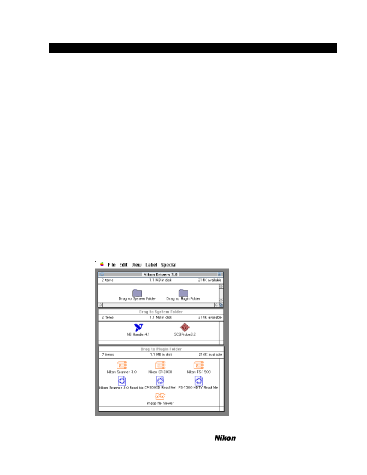
Owner’s Guide. Insert your backup Nikon Drivers disk into the drive. The disk
icon will appear on your desktop and three windows containing folders will appear
in a vertical column on the left side of your screen, as shown below.
Fig. 1 Desktop
Software Reference for Scanners
Page 18

1-2 Software Installation - Macintosh
If you are using a GPIB interface, select the NB Handler Init in the folder
labeled Drag to System Folder and drag it onto the System Folder on your hard
disk. It will be copied into the Control Panels folder if you are using System 7.
>Caution If you already have a file called NB-Handler INIT installed in your system
folder, move it to another folder before you copy the new file in.
Next, drag the Nikon Drivers disk icon onto your hard disk icon and follow
the prompts. Double click on your hard disk icon to reveal its contents. Now
double click on the Nikon Drivers folder to display the NB Handler Init, the
plugin modules, and the ReadMe documents.
If you are using the built-in SCSI interface on the Macintosh, connect the
DB25 to SCSI II cable adapter to the rear panel connector on the Mac and then to
the Mini 50 pin connector on the Nikon scanner. If this is the only unit on the
SCSI bus, connect a terminator to the second plug on the scanner. Restart your
Macintosh and go on to Using the Plugin Scanning Module.
Configuring and Testing the GPIB
If you are using an NB-GPIB interface card, the NB Handler Init must be in
your startup (boot) disk’s System Folder in order for the plugins to work properly.
Using System 7, it should be in the Control Panels folder.
In order for the NB-GPIB interface to communicate properly with the Nikon
Plugins, the NB Handler control panel should be configured to your device address
settings. In particular, it is necessary that the GPIB finds a device called LS-
3510AF, which is the LS-3510AF Film Scanner (or in the case of the LS-3500
scanner, LS3500), when the plugin looks for it. Similarly, if you are using a CP3000 printer, then the name CP-3000 must be used by the NB Handler to indicate
the device. If your NB Handler does not have your scanner or printer address
configured properly, the GPIB may not communicate with the device connected.
If you have an old version of the handler in your system folder, remove it
temporarily and replace it with the new version from the Nikon Drivers disk. This
is a preconfigured file for the Nikon LS-3500, LS-3510AF, CP-3000D and FS1500 devices. Using this Init will get you running in the least amount of time and
you can reconfigure for other devices later on. If you are using the preconfigured
NB Handler, confirm its correct installation by restarting your machine and
opening your NB Handler control panel from your Control Panels under the Apple
Menu.
Software Reference for Scanners
Page 19
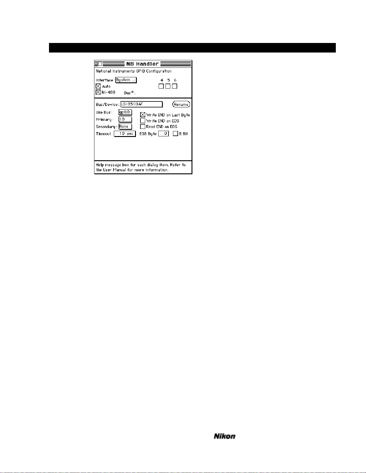
Software Installation - Macintosh 1-3
Fig. 2 NB Handler control panel
Check to see that the addresses are correctly entered and conform to the
factory default settings of the device DIP switches. If so, proceed to the next
section, Using The Macintosh Plugin Scanning Module.
If you wish to change the configuration, use the rename button to change any
devx setting to the appropriate name of the device. Set the address in the text-edit
box labeled Primary. It is not necessary to restart your machine for the changes to
take effect. Simply close the Control Panel and go on to Getting Started.
>Note If you have an older NB Handler Init installed it may not be of the control
panel type and will not show up in your Control Panels folder. If so, you can
use the IBCONF utility usually supplied with your National Instruments NBGPIB board to add the Nikon configuration to your old Init, or you can
modify the new one with the control panel shown above to include your other
devices, such as film recorders and other scanners.
Software Reference for Scanners
Page 20

Page 21
Software Installation - IBM 2-1
Installing the Plugin Modules under Windows 3.1
If you have not already done so, install PhotoStyler following Aldus’
installation procedure. If you are using another application, then follow the
installation routine specified by the manufacturer.
After you have installed and tested your image processing application, you
are ready to install the Nikon Plugin modules. If you are using PhotoStyler they
should be placed in the PhotoStyler directory.
>Note This plugin works with PhotoStyler 1.0 or later
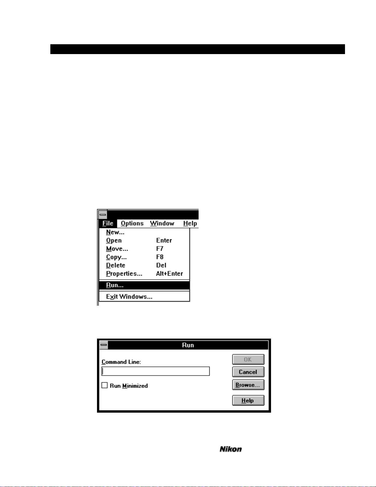
Launch Windows. If you are unfamiliar with how to do this, please refer to
the Microsoft Windows Owners Guide.
Insert your backup Nikon Installer Disk in your floppy drive - drive A: for
example.
Fig. 3.The Program Manager File Menu
Select Run... from the File menu in the Program Manager.
Fig. 4 The Run... Dialog
Software Reference for Scanners
Page 22
2-2 Software Installation - IBM
Type A:PSSETUP and press enter. Press any key or click the mouse to skip
the startup screen.
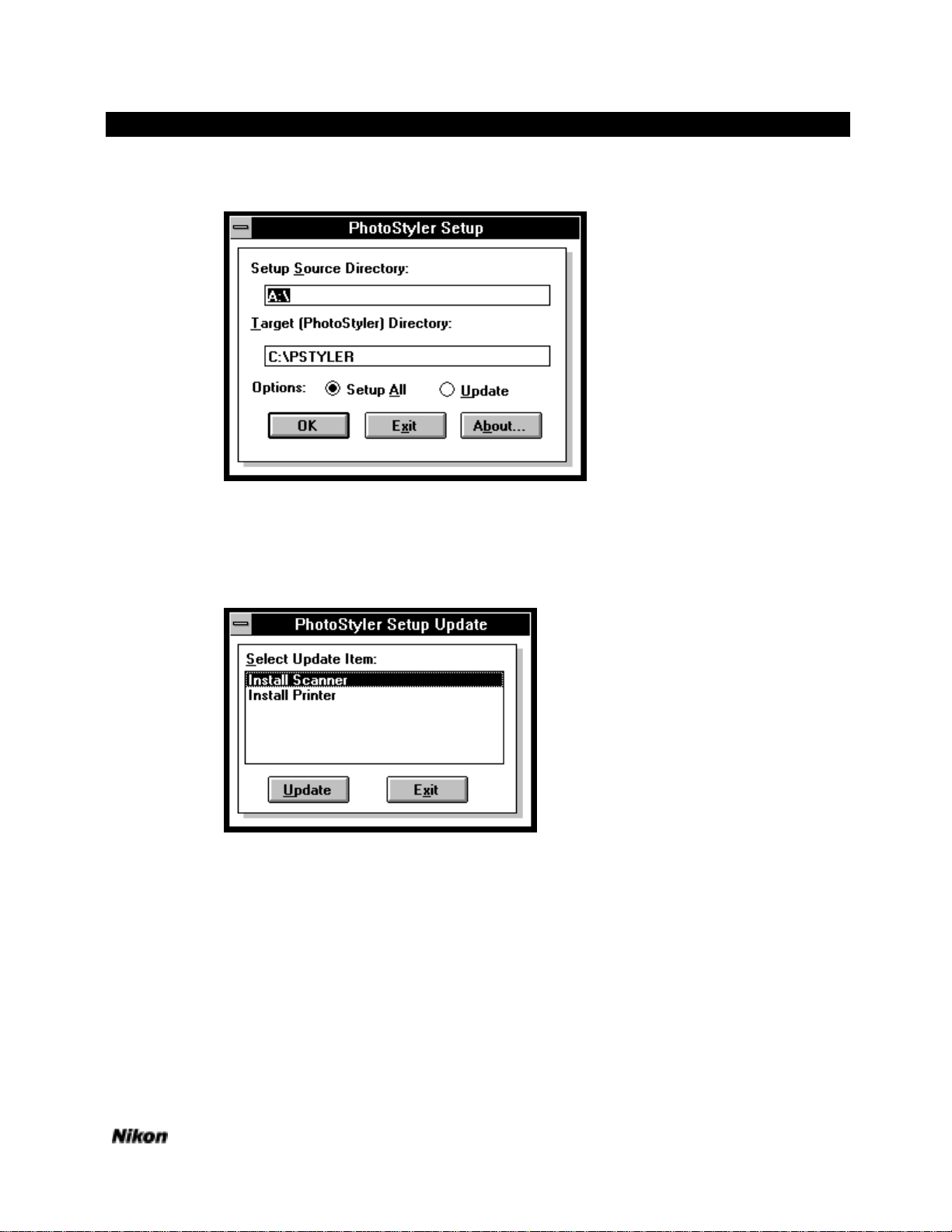
Fig. 5 PhotoStyler Directories
Enter your source and target directories. To install only the Scanner Plugin or
the Nikon CP-3000 printer export, check the Update box before pressing the OK
button. Choosing Setup All will install all the plugins on the disk.
Fig 6 Installing the scanner
If you are updating the scanner, choose the Install Scanner selection.
Software Reference for Scanners
Page 23
Software Installation - IBM 2-3
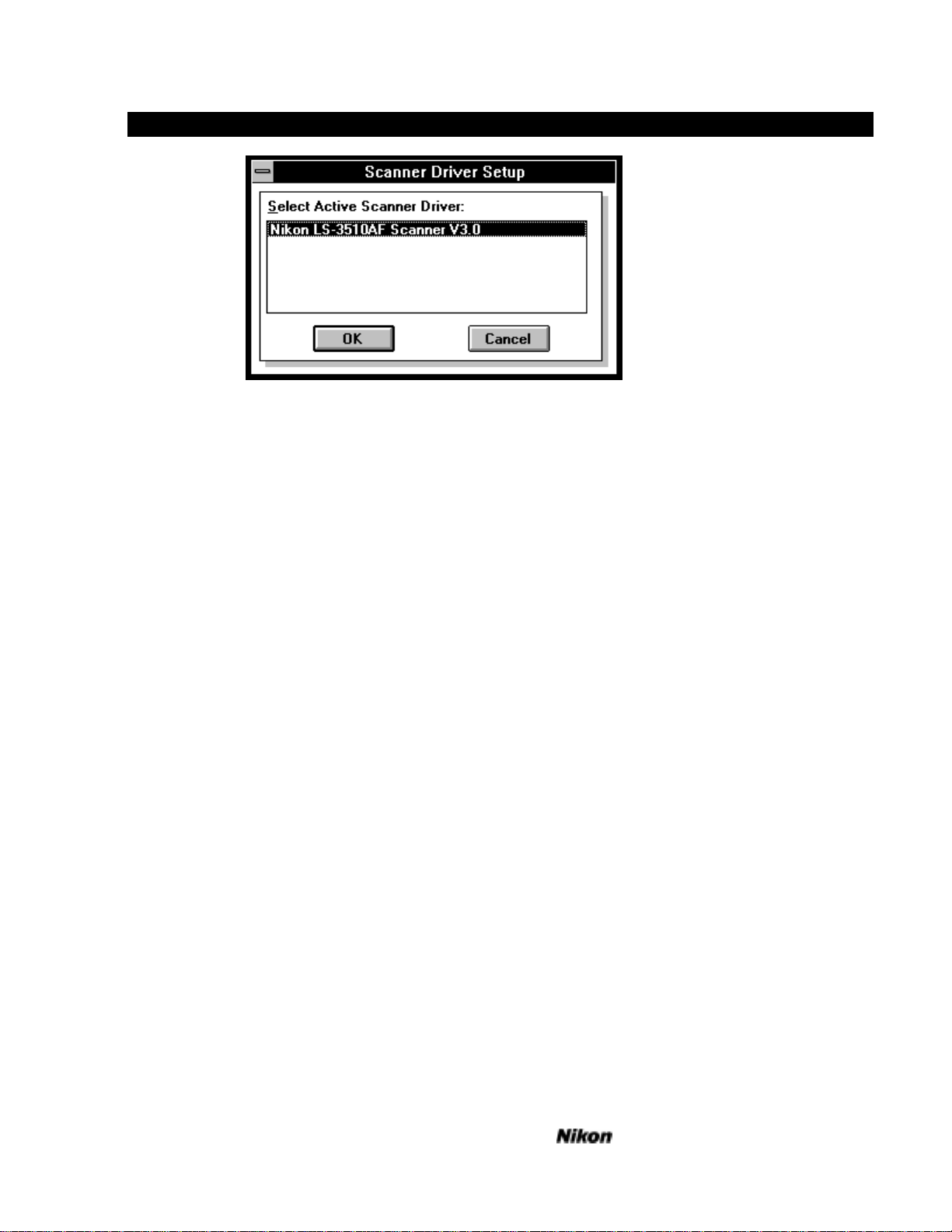
Fig. 7 Selecting the active scanner for PhotoStyler
You must choose which scanner driver to make active in PhotoStyler. Since
only one driver is available, click OK.
Your drivers are now installed and you can proceed on to the Getting Started
section for the Windows plugins.
Interface Hardware for PC Compatibles
For complete information on installation of GPIB hardware consult your GPIB
installation manual which comes with your GPIB board.
As with any interface board installation, ensure that there are no address,
interrupt or DMA channel conflicts between any boards installed in your
computer.
GPIB (General Purpose Interface Bus)
Currently, only the National Instruments AT-GPIB and MC-GPIB boards are
supported. When installing the software drivers for these boards, be sure to select
the installation for Windows. National Instruments can be reached at
1-800-IEEE-488 (1-800-433-3488).
SCSI (Small Computer Systems Interface)
Any SCSI board with ASPI (Advanced SCSI Programming Interface) drivers
should work, but only the T128 and T228 from Trantor and the AHA-1520, AHA1522, AHA-1540B, AHA-1542B, AHA-1640 and AHA-1642 from Adaptec have
been verified. Trantor can be reached at 1-510-770-1400 and Adaptec can be
reached at 1-800-869-8883. The ASPI drivers may not be included with the
standard software bundle and may have to be specifically requested.
Software Reference for Scanners
Page 24

Page 25
Getting Started On The Macintosh 3-1
Getting Started on the Macintosh
Launching the Application
Launch Photoshop or ColorStudio by double clicking the appropriate icon.
Pull down the File menu to reach the Acquire... menu item and select Nikon
Scanner... from the hierarchical menu. The main scanning dialog will appear as
below and the Device: and Address: lines should indicate that there is a scanner
connected. If the dialog appears as below, you are ready to start scanning and can
proceed to Scanning a Preview Image.
Fig. 8 Main Scanning Dialog
If the message in the upper left-hand corner reads “Nikon LS-3510AF Ver
1.xx” on either a SCSI or GPIB interface, you are ready to make a preview or
scan. If not, the plugin has not found the scanner and you will need to check your
SCSI or GPIB cabling, confirm tight connections and proper termination. For
SCSI installations with other external devices, place the scanner at the end of the
chain with the standard supplied terminator for your machine. If you are unsure
what GPIB or SCSI address to use, consult the Setup Guide included with your
scanner.
Software Reference for Scanners
Page 26
3-2 Getting Started
Scanning a Preview Image
Take out the sample slide included in the disk holder. You will be using the
Standard Slide Holder for this scan. Hold the mount as in the diagram in Fig. 9
below. Insert the slide so that the emulsion side of the film faces the front of the
scanner. When viewing the slide orient the picture so the text is readable. The
emulsion side is the surface furthest away from you. Since the LS-3510AF is an
autofocus scanner, it will not make much difference which way you place the
emulsion (other than image orientation, right-reading or backwards), although
sharpest results will be achieved when the emulsion faces the front of the scanner
because the imaging lens will not be reading the film through the film base, which
may reduce definition, depending on the film type.
Sample
35mm film
in slide mount
Standard Holder
Scanning Stage
Light source
Fig. 9 Loading the Scanner
Insert the Slide Holder into the scanner so that the slide mount is closest to
the lamp. Close the dustproof cover so that the outside light does not affect the
scan.
The sample slide is a portrait (or a vertical image) but we will leave the
default scanning orientation in the horizontal or landscape position.
Fig. 10 Orientation
Software Reference for Scanners
Page 27
Getting Started On The Macintosh 3-3
The quickest way to capture this image is to click the Preview button.
Fig. 11 Previewing an Image
In order to scan the slide under optimal conditions, the LS-3510AF will first
perform an autoexposure and autofocus sequence to determine information about
the nature of the image in the holder.
You should see the green Busy LED light up on the scanner and a message
appear in a small dialog. The message should read Performing an
autoexposure... This status line will keep you informed about the scanner’s
progress.
When the green Busy LED on the LS-3510AF goes out, you have completed
the Autoexposure cycle and the scanner will automatically focus on the slide
displaying the message, Performing autofocus... After this, the Busy LED will
immediately light up again and the scanner will begin the preview cycle as it reads
the picture directly to your monitor display, field by field. We can now see the
image appearing on the video screen in the scan window in the sequence red,
green, then blue screens.
>Note You will not be able to see the high-quality color available from the scanner
unless you have a 24-bit display card installed in your system. Using an 8-bit
card will display a dithered image.
Final Scan
The next step will be to perform the main scan at a higher resolution. Crop
the preview image by placing the cursor at any corner of the preview, and dragging
to enclose the area of interest in a rectangle as in Fig. 12 below.
Fig. 12 Cropping the Preview Image
Software Reference for Scanners
Page 28

3-4 Getting Started
The resolution setting under the preview window can be left at the default
setting of 72DPI. The approximate size of the output image should be 6 x 8
inches.
You are now ready to complete the final scan. Click on the scan button at the
lower right of the Main dialog. The scanner will begin the scanning cycle, making
three successive passes for red, green and blue. Within a moment or two, a
progress indicator dialog will appear, showing the approximate duration of the
scan and the portion remaining to be completed.
Fig. 13 Scanning Progress Indicator
Be sure not to open the dust cover during the scan. If it is opened, extraneous
light could adversely affect your scan and cause density changes to appear in the
image. This scan will take approximately 45 seconds to complete. A new window
containing the image and labeled Untitled-1 will appear after the scan is complete.
You may save the image in the normal manner or close the window and begin
again.
Conclusion
You have completed Getting Started! Feel free to continue exploring on your
own, but if you need quick answers to any questions, don’t hesitate to consult the
User's Guide following this section. It provides complete descriptions of the plugin
controls so you can exploit the full functionality of your Nikon scanning system.
Software Reference for Scanners
Page 29

Getting Started On The IBM 4-1
Getting Started on the IBM
Launching the Application
Launch PhotoStyler by double clicking the appropriate icon.
Pull down the File menu to reach the Scan... menu item and select Nikon
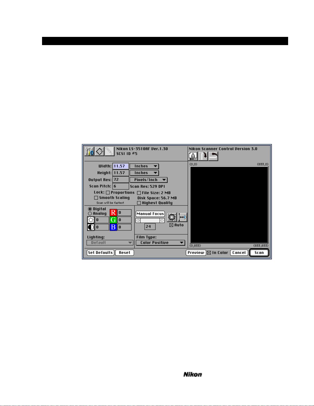
Scanner Control... from the hierarchical menu. The main scanning dialog will
appear as below and the Device: and Address: lines should indicate that there is a
scanner connected. If the dialog appears as below, you are ready to start scanning
and can proceed to Scanning a Preview Image.
Fig. 14 Main Scanning Dialog
If the message in the upper left-hand corner reads “Nikon LS-3510AF Ver
1.xx” on either a SCSI or GPIB interface, you are ready to make a preview or
scan. If not, the plugin has not found the scanner and you will need to check your
SCSI or GPIB cabling, confirm tight connections and proper termination. For
SCSI installations with other external devices, place the scanner at the end of the
chain with the standard supplied terminator for your machine. If you are unsure
what GPIB or SCSI address to use, consult the Setup Guide included with your
scanner.
Software Reference for Scanners
Page 30

4-2 Getting Started On The IBM
Scanning a Preview Image
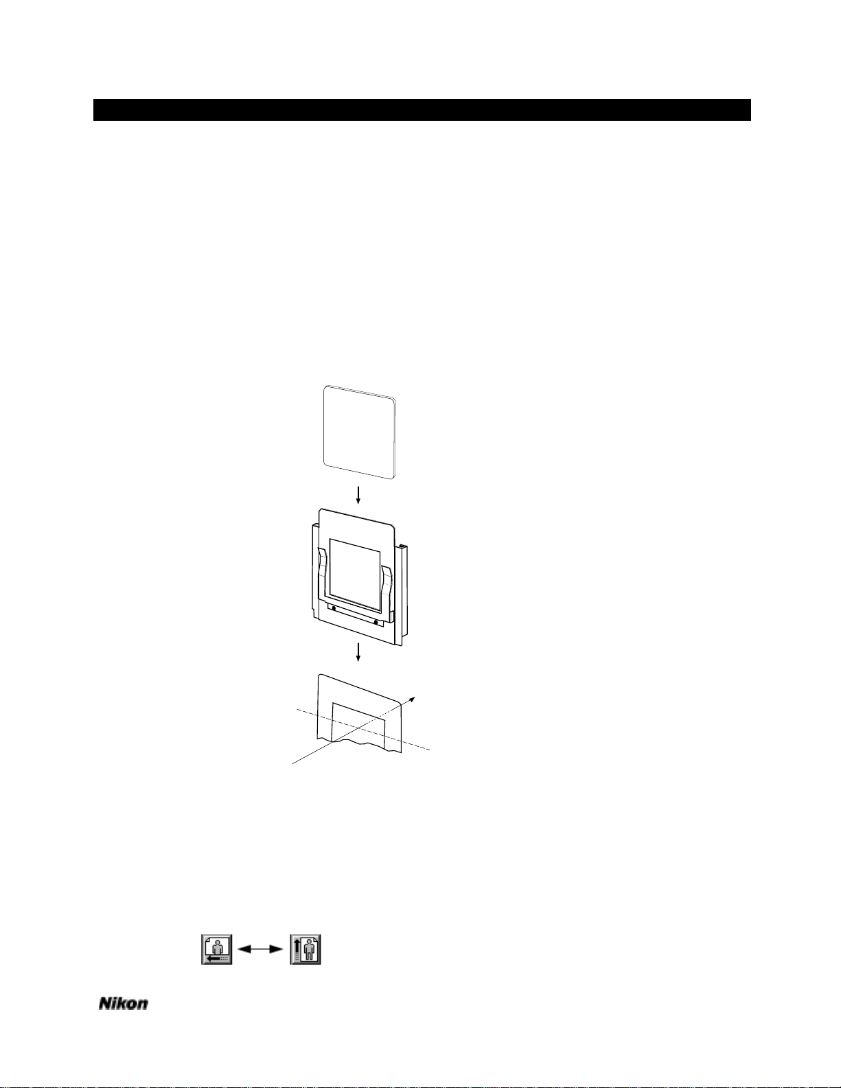
Take out the sample slide included in the disk holder. You will be using the
Standard Slide Holder for this scan. Hold the mount as in the diagram in Fig. 15
below. Insert the slide so that the emulsion side of the film faces the front of the
scanner. When viewing the slide orient the picture so the text is readable. The
emulsion side is the surface furthest away from you. Since the LS-3510AF is an
autofocus scanner, it will not make much difference which way you place the
emulsion (other than image orientation, right-reading or backwards), although
sharpest results will be achieved when the emulsion faces the front of the scanner
because the imaging lens will not be reading the film through the film base, which
may reduce definition, depending on the film type.
Sample
35mm film
in slide mount
Standard Holder
Scanning Stage
Light source
Fig. 15 Loading the Scanner
Insert the Slide Holder into the scanner so that the slide mount is closest to
the lamp. Close the dustproof cover so that the outside light does not affect the
scan.
The sample slide is a portrait (or a vertical image) but we will leave the
default scanning orientation in the horizontal or landscape position.
Fig. 16 Orientation
Software Reference for Scanners
Page 31

Getting Started On The IBM 4-3
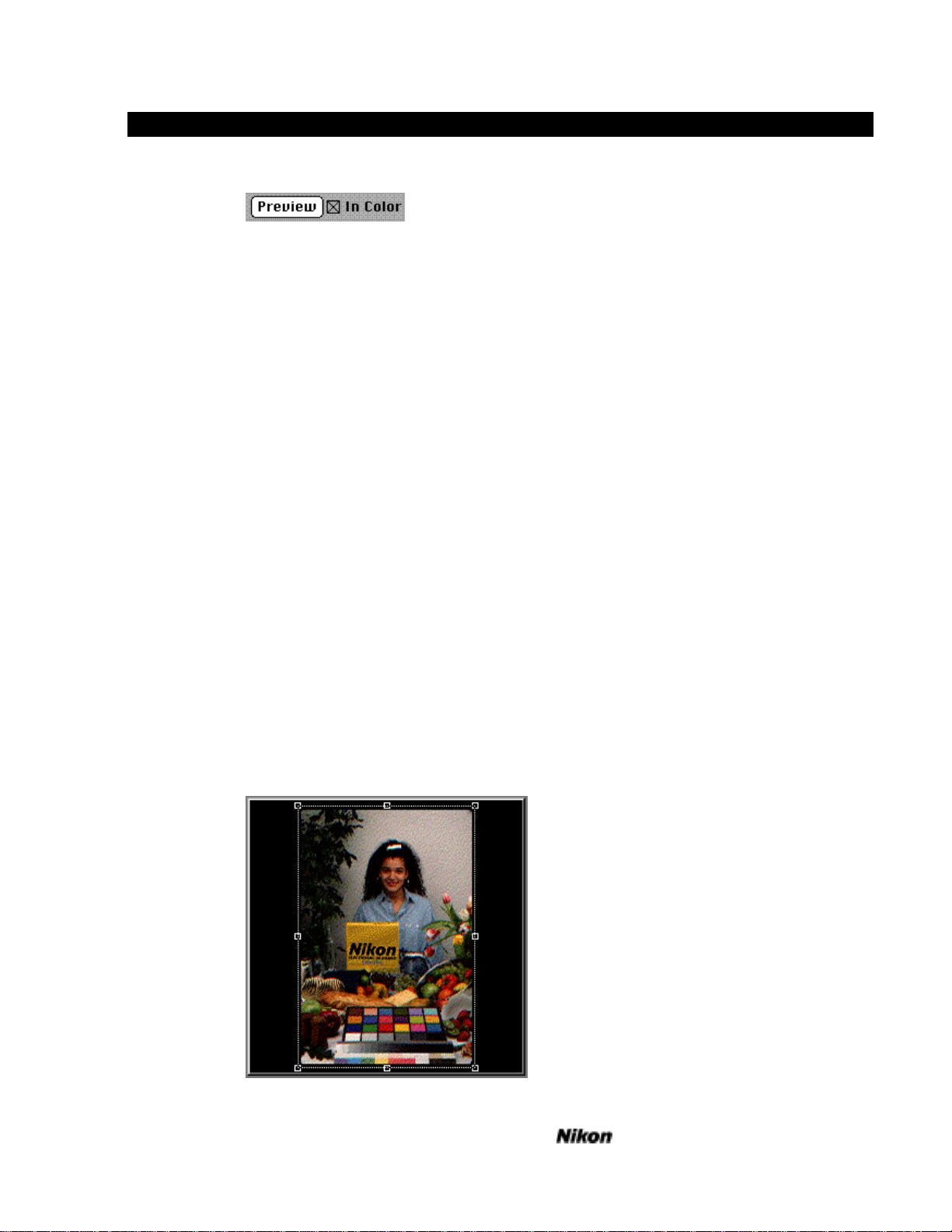
The quickest way to capture this image is to click the Preview button.
Fig. 17 Previewing an Image
In order to scan the slide under optimal conditions the LS-3510AF will first
perform an autoexposure and autofocus sequence to set up information about the
nature of the image in the holder.
You should see the green Busy LED light up on the scanner and a message
appear in a small dialog. The message should read Performing an
autoexposure... This status line will keep you informed about the scanner’s
progress.
When the green Busy LED on the LS-3510AF goes out, you have completed
the Autoexposure cycle and the scanner will automatically focus on the slide
displaying the message, Performing Autofocus. After this, the Busy LED will
immediately light up again and the scanner will begin the preview cycle as it reads
the picture directly to your monitor display, field by field. We can now see the
image appearing on the video screen in the scan window in the sequence red,
green, then blue screens.
>Note You will not be able to see the high-quality color available from the scanner
unless you have a 24-bit display card installed in your system.
Final Scan
The next step will be to perform the main scan at a higher resolution. Crop
the preview image by placing the cursor at any corner of the preview, and drag to
enclose the area of interest in a rectangle as in Fig. 18 below.
Fig. 18 Cropping the Preview Image
Software Reference for Scanners
Page 32

4-4 Getting Started On The IBM
The resolution setting under the preview window can be left at the default
setting of 100DPI. The approximate size of the output image should be 10 x 15
inches.
You are now ready to complete the final scan. Click on the scan button at the
lower right of the Main dialog. The scanner will begin the scanning cycle, making
three successive passes for red, green and blue. Within a moment or two, a
progress indicator dialog will appear, showing the approximate duration of the
scan and the portion remaining to be completed.
Fig. 19 Scanning Progress Indicator
Be sure not to open the dust cover during the scan. If it is opened, extraneous
light could adversely affect your scan and cause density changes to appear in the
image. This scan will take approximately 45 seconds to complete. A new window
containing the image and labeled Untitled-1 will appear after the scan is complete.
You may save the image in the normal manner or close the window and begin
again.
Conclusion
You have completed Getting Started! Feel free to continue exploring on your
own, but if you need quick answers to any questions, don’t hesitate to consult the
User's Guide following this section. It provides complete descriptions of the plugin
controls so you can exploit the full functionality of your Nikon scanning system.
Software Reference for Scanners
Page 33

Using The Macintosh Scanner Plugin 5-1
Using the Macintosh Scanner Plugin
Let’s begin with a full description of the main and auxiliary dialogs. All of
the plugin controls follow the standard Macintosh interface design. If you are
unfamiliar with the operation of the Macintosh interface, please consult your
owner’s manual.
The examples in this reference were used with the LS-3510AF in mind.
Other Nikon scanners will vary slightly in their feature set, although all Nikon
scanners can be controlled with this software.
The Main Dialog
In this section we will discuss each menu and dialog box in detail. The main
dialog looks like this:
Fig. 20 The Main Scanning Dialog
Software Reference for Scanners
Page 34

5-2 Using The Macintosh Scanner Plugin
Controls and Indicators
The purpose of each control and dialog item is discussed below.
Status Line
Fig. 21 Status Line
A status and information line is displayed when an action is begun. Messages
include the current scanner condition and routine being performed. For example,
when the Autoexposure button is pressed, the message will read Performing an
autoexposure...
Film Type
Fig. 22 Film Type
This pop-up menu allows the user to specify film type regardless of what kind
of film is placed in the scanner. If a monochrome scan of a negative color image
is desired, you should choose B & W Negative. The Autoexposure measurements
are compensated according to tone range of the average color values. If a unique
color tone separation is required, a color scan can be made and the appropriate
color channel can then be manipulated in the image processing application to
achieve the desired color/tone balance in black and white.
Software Reference for Scanners
Page 35

Using The Macintosh Scanner Plugin 5-3
This pop-up menu also specifies color and density processing for negative or
positive film types. Since color negative film is not simply the inverse of color
positive film (because of the orange mask used in negative film types), accurate
color and density balance can only be achieved by using analog processing of
gamma and exposure. Accurate, higher quality color is maintained by using this
control to modify the balancing parameters in the analog section of the scanner
rather than in the image processing application where loss of bits and tone range
will result.
To register and calibrate to a new color negative film type, insert a processed
unexposed strip of film into the scanner, and close the cover. Choose Register
from the Film Type pop-up menu and the following dialog will appear.
Fig. 23 Registering Film Type
Type the name you wish to use to indicate this film; no more than 13
characters. The register button will be enabled, and pressing it will start the
calibration cycle in the scanner. This is a custom calibration specific to the film
and processing that you are using. You can store up to 24 custom film types in the
scanner. You can delete any of these film types by using the Delete... menu item
if you need to make space for a new film type.
The calibration provides a neutral black point from the orange clear base of
color negative films. Another way to calibrate is to photograph three aim points.
Place a black card, preferably velvet, an 18% reflectance gray card and a matte
white card in the frame. After processing, place this frame in the scanner in
vertical orientation and go through the same registration procedure.
For more accurate calibration, you can use a five step grayscale for even
closer correction values. Make sure that it is photographed at 5500°K. In
addition, color transparency film can be calibrated the same way. When not using
a grayscale, make sure that an unexposed piece of negative processed film is used.
Insert the processed film so that the gray wedge is vertically oriented in the
scanner.
Software Reference for Scanners
Page 36

5-4 Using The Macintosh Scanner Plugin
Fig. 24 Photo of Gray Step Wedge
Orientation
Portrait/Landscape
Fig. 25 Portrait/Landscape Orientation Switch
This button specifies orientation of the resulting scan from a normally
mounted original. If the original is placed in the scanner in a normal orientation as
viewed from the front, then the landscape button will produce the same orientation
on output to the screen. Depress the button to reveal the portrait icon and the
resulting scan will be rotated 90° from the position it was in the scanner film gate.
Vertical/Horizontal Flip
Fig. 26 Vertical/Horizontal Flip
After previewing the image you may wish to reverse from right-reading to
wrong-reading (i.e. a left/right flip). This is most useful when you wish to flop the
image because you have to scan it with the emulsion facing the front of the
scanner when maximum sharpness is required, avoiding scanning the image
through the base of the film. In the vertical orientation, you can save time if you
inadvertently place the film in upside-down. These buttons stay depressed for the
main scan. If there is slight speed degradation re-orienting a very high resolution
scan, it may be worthwhile to re-orient the film before scanning.
Densitometer
Fig. 27 RGB/CMY Densitometer
You can measure RGB or CMY values anywhere in the preview scan by
placing the cursor over the area of interest. Three numbers will appear at the top
of the preview frame, initially in RGB 8-bit notation (0-255). Holding down the
Command key (1) and clicking the mouse will change the notation to CMY
values from 0-100% where 100% equals maximum density.
Software Reference for Scanners
Page 37

Using The Macintosh Scanner Plugin 5-5
Sizing and Resolution
Fig. 28 Resolution and Size Controls
The scanner's total scan area is a 5000 pixel by 5000 pixel scan covering 40 x
40 millimeters. This makes for a direct-reading scan resolution of 3175 pixels per
inch, or 125 pixels per millimeter. All lower resolution scans are substituted from
this.
A standard 35mm frame has a scannable area of approximately 36mm by
24mm; or 4500 pixels by 3000 pixels at highest resolution. Full frame scans are
typical in most applications.
The actual scan area in Figure 29 is shown as the gray square, while the film
area is shown in white, superimposed over the scan area. The corner coordinates
are the actual pixel coordinates of the scanner's pixel array given in (x, y) form.
Fig. 29 Scan Area of the LS-3510AF
The scanner's "natural" orientation encourages you to place the film into the
scanner with the emulsion facing the light source. You will be the best judge of
whether or not this is how you wish to view the image. The tall/wide and scan
orientation, and the horizontal and vertical "flips" will allow you to view the image
in any way that you like. Figure 30 shows the scan specification area as it appears
in the dialog. The values are the factory defaults for the LS-3510AF scanner
plugin.
Software Reference for Scanners
Page 38

5-6 Using The Macintosh Scanner Plugin
Fig. 30 Resolution and Size Controls
These text edit boxes allow you to enter sizes directly in inches, centimeters
or pixels for either dimension. The numbers can be entered before or after a crop
has been drawn around the subject. One method is to type in the exact numbers
for the final size and resolution, and then lock the File Size and draw the crop box
which will now be constrained. The resolution can also be interpreted based on
CCD Pixels using a 'pitch' number. This is an integer which is used to divide the
total resolution of 5000 pixels. For example, if one enters a value of five, then the
resulting resolution will be 5000 divided by 5, or 1000 pixels over the full 40mm
dimension of the scanning aperture, or 25 pixels/mm, 635 pixels per inch.
Scan Pitch
Scan Pitch is the number of scan area pixels that go into one pixel of the final
output image. If a scan was made at pitch 2, with the crop (shown in Figure 18) of
250, 1000, 4750, 4000; the actual scan would measure 2250 pixels by 1500 pixels
tall; or 1/2 the resolution of the scanner's full scan capability at 1588 pixels per
inch. The image would still cover the area described above, but every other pixel
would be skipped in the scan. Scan pitch is inversely proportional to the native
scanner resolution.
The scanner hardware does not process fractional, or non-integer pitches.
Pitches other than integer pitches are interpolated with an extra scaling step in the
final scan. This can lead to some performance attrition, depending upon the pitch
involved. If the plugin determines that speed may be affected, a small warning
appears in the dialog just below the output scan specification area.
The range of the Scan Pitch does not go below pitch 1, or above pitch 50.
The scan is specified though a combination of selecting a crop in the preview
area, and typing scan parameters into the editable text items displayed above.
There are different approaches that can be taken when defining a scan.
In the first example, to produce an 8 inch by 10 inch image suitable for 150
line screen output, set the height and width unit pop-up menus to inches, and the
resolution units to pixels/inch. Then just type 8 into the width edit field, 10 into
the height edit field, and 300 (for a good half-tone screen of 150) into the
resolution edit field.
Software Reference for Scanners
Page 39

Using The Macintosh Scanner Plugin 5-7
> Note Although the ratio of scanned pixels to output halftone dots is traditionally
2:1, ratios as low as 1:1 can be acceptable in certain applications. We
recommend 1.5:1 for most medium to high resolution four color offset
reproduction.
Fig. 31 Resolution and Size Controls
The crop will automatically resize itself as you do this, and you will end up
with the following display:
Fig. 32 Preview Window Crop
The scan pitch automatically changes to allow for the scan size requested.
You may now move the crop to cover any area of the preview that you wish
to scan by placing the crosshair cursor over the crop box, holding down the mouse
button and dragging the box to the new location.
If you now want to shrink or expand the crop while keeping the same output
resolution and size, you must check the File Size: checkbox. You will now be
able to resize the crop without worrying about changing your output scan
parameters.
In the second example, select a crop in the preview area, and then make the
crop 8 inches wide at 300 dpi. After that, make it 10 inches tall. The important
thing is to get it wide enough to include the elements that you wish to see.
Software Reference for Scanners
Page 40

5-8 Using The Macintosh Scanner Plugin
First, you should select the crop with the mouse:
Fig. 33 Mouse Selected Crop
The resolution specification items may now look like this for the above crop:
Fig. 34 Specifications for Mouse Selected Crop
Now, check the Proportions checkbox. This will allow you to enter a height
or width value without changing the aspect ratio. Type 8 into the width edit field.
The resolution specification items will look like this:
Fig. 35 Lock Proportions
Note the little lock in the previous figure. That means that any changes in
width will cause a change in height to keep the scan rectangle in the same aspect
ratio as before. That is what locked proportions means. The value in the height
edit field changed to 6.4.
Software Reference for Scanners
Page 41

Using The Macintosh Scanner Plugin 5-9
Since you don't want the width to change, unlock the proportions and type 10
into the height field. The crop's length will change, and you will have an 8" x 10"
crop area in the main crop selection area. Type 300 into the resolution field, and
you have the following:
Fig. 36 Changing Resolution
The crop in the main preview area will look like this:
Fig. 35 Specification Crop
If you attempt to type in a number that is too large, the plugin will beep and
the closest acceptable value will be substituted.
Experiment with the crop selection to see how you can best make use of it. It
will allow enough flexibility to enable any scan that you may wish to make.
Software Reference for Scanners
Page 42

5-10 Using The Macintosh Scanner Plugin
The Smooth Scaling checkbox sets a pixel averaging interpolator to produce
smoother pixel transitions in low resolution (Pitch 5 to 50) scans.
Fig. 36 Smooth Scaling Checkbox
The Highest Quality checkbox will cause the scanner to take the scan in a
special slow-speed mode to improve the registration accuracy in low resolution
scans (from pitch 5 to pitch 50). In almost all cases, the difference from the
normally high-quality fast scans will be negligible.
Fig. 37 Highest Quality Checkbox
Scanning Speed
There are several ways to optimize scanner performance.
You should allow Adobe Photoshop to have as much memory as possible. In
order to do this, you should find the application in it's home folder, select it with
the mouse, then select the Get Info menu item in the File menu. A dialog will
appear with two boxes in the bottom right corner: Suggested Size, and Current
Size (in System 7). The Current Size box will be editable. Type in a number
greater than that in Suggested Size, and at least 2 MB less than your maximum
system memory size. When Adobe Photoshop is launched after this, it will use the
maximum possible memory up to the value that you typed in. If you consistently
get a dialog that tells you that the application will be opened in a smaller partition,
you should go back into the "Get Info" dialog, and reduce the memory
requirements.
System 7 users should have 32-bit addressing on and virtual memory off in
the memory control panel for best performance with greater than 8MB of RAM
installed. Minimum requirements for higher performance at high resolution are
32MB installed RAM, addressable under System 7.0.
Scan in Portrait mode and place the slide in the holder in the appropriate
position to get the right preview orientation. This delivers data to Adobe
Photoshop in a more efficient manner than Landscape mode. You might select
the crop in Landscape mode, then switch it to Portrait mode just before the scan
is to be made.
In some cases, Flips may slow the scan by a small amount. Experiment to
see which delivers the best results for you.
Try to use an integer pitch setting. These will always be more efficient than
non-integer pitches. Experiment with selecting crops and specifying integer
pitches for them.
Software Reference for Scanners
Page 43

Using The Macintosh Scanner Plugin 5-11
The Highest Quality checkbox will significantly slow scans. Make sure that
you absolutely need the advantages that it provides for low resolution scans.
Finally, different images will have varying scan times dependent upon their
density. When the scanner makes an autoexposure, it decides upon some baseline
parameters to optimize the image to be scanned. One of these parameters is
exposure time for each color. Higher densities require longer scan times.
Grayscale/Color Preview
Fig. 38 Previewing in Color
Pressing the Preview button will cause a preview scan to be taken. To
preview your image in color, check the In Color checkbox. Previewing in
grayscale allows fast black and white previews of color scans when a quick scan
and crop is required for expediency.
Interface Buttons
Fig. 39 Interface Button
This toggling pair specifies SCSI or GPIB interface. While opening the
plugin, the software will search the GPIB and then the SCSI bus for any scanners.
When found, the device found will have its ID displayed in the upper right-hand
corner. If no device is found, and one is known to be connected, then the toolkit
button provides a means to search the bus again for a particular address.
Digital and Analog Controls
Fig. 40 Digital Control Fig. 41 Analog Control
In order to save dialog space, and to keep the user interface as uncomplicated
as possible, we have assigned dual roles to the five edit items in the lower left
hand corner of the Main Scanning Dialog. These items double as brightness,
contrast, and tint level (digital), and as exposure time, black level, and color
balance (analog). The principal difference between the two types of adjustments is
that analog adjustments work on the actual CCD voltage levels and exposure
times; while the digital adjustments work on the data after it has been collected
from the CCD and digitized within the scanner. The advantages of using the
Software Reference for Scanners
Page 44

5-12 Using The Macintosh Scanner Plugin
analog controls is that they minimize data loss for large changes, such as
compensating for dense images or heavy color casts. In most cases, the digital
controls will afford plenty of control for the kind of minor adjustments that are
usually made. The two figures above show how the two types of control sets will
appear, dependent upon the state of the Digital/Analog radio button pair.
Adjusting these numbers will produce a change in the preview image on screen.
Digital Mode
The digital controls all have a range from -5 to +5 with a nominal value of 0.
All these controls alter the gamma in a LUT (Look Up Table) that follows the A/D
(analog to digital) conversion in the scanner. The gradation changes are minor but
noticeable, and will be simulated in the preview without re-scanning. Best results
will be achieved with the optional 12-bit board installed when using these controls.
Analog Mode
The analog controls have a range of 0 to +255 for the brightness (exposure),
and color balance controls, with a nominal value of 50, and -15 to +15 for the
contrast (black level) control, with a nominal value of 0. There are five Text edit
boxes controlling Exposure, Black level, and RGB color balance.
Adding to any value when scanning positives will shift the color in that
direction. When scanning negatives, adding to the value removes that color. You
can directly control Red, Green, and Blue gain settings from 20 to 120. The
numbers that you input affect the reference value that was determined at Prescan
Photometry. This reference will always be 50, so that the resulting change in
exposure when these controls are manipulated is calculated as follows:
• 25=25/50 = .5 = 50% - meaning an exposure decrease of 1 stop (in
photographic terminology).
• 50=50/50 = 1 = 100% - meaning no increase or decrease in exposure.
• 75=75/50 = 1.5 = 150% - meaning an exposure increase of 1/2 stop
• 100=100/50 = 2 = 200% - meaning an exposure increase of 1 stop.
You cannot shorten the exposure time to be less than the minimum exposure
determined by prescanning. This is very often ~40. You may also find that the
CCD can oversaturate on specular highlights when the exposure time is increased
beyond ~100. The best application of these controls is to greatly alter the densities
and color balance of a scan. For example, if an image is too green, the green
exposure for a color positive can be decreased. Another way to counteract the
overall green cast is to increase the Blue and Red exposures by equal amounts.
Equal amounts of Blue and Red are equivalent to the same amount of Magenta,
which is the complimentaryoor opposite color to Green and will neutralize it.
> Note When increasing the analog exposure for a Positive scan, the resulting image
or color will be lighter than before. When increasing the analog exposure for
a Negative scan, the resulting image or color will become darker.
Software Reference for Scanners
Page 45

Using The Macintosh Scanner Plugin 5-13
The same rules apply to Exposure. Changing the exposure values here will
affect Red, Green and Blue settings by an equal amount. This is a simple way to
increase the brightness of a dark original transparency, without affecting the color
balance of the resulting image. Again, the useful range of values typically falls
between 40 and 120.
The Black Level ranges from -15 to +15. This setting determines the
clamping level of the CCD for the maximum black in the image. Usually, the
(or darkest black) of an Ektachrome transparency measures 3.0 on a
D
max
densitometer. The D
(the lightest portion or specular highlight) often measures
min
.8, making the overall range 2.4. This density range of dark to light is very typical,
but much higher than what we usually print on paper. The Black Level Threshold
control permits the user to lighten or darken the blackest black in the image. This
means that as we lower the setting (when scanning positive film), the blacks will
get lighter and as we raise the setting, they get darker. This happens without
affecting the highlights or midtones of the image.
Auto Exposure/Auto Mode
Fig. 42 Auto Exposure / Auto Mode
The autoexposure icon (the icon on the left) will cause the scanner to do
what's referred to as a Prescan. That is, the scanner adjusts itself to the image by
determining density and contrast. It optimizes it's internal analog levels to make
the best scan possible. In most cases, the autoexposure will do such a good job
that you won't need to adjust the analog or digital controls.
The Auto Mode checkbox means that the plugin will ensure that the scanner
has made at least one autoexposure and autofocus before a preview or scan is
attempted. This will be reset if the film type is changed, or if Photoshop is quit,
then re-launched.
One of the really important features of the LS-3510AF is it's focusing and
auto-focusing features. This eliminates the need for different thickness slide
holders, as used by the LS-3500. In almost all cases, the standard autofocus (the
icon on the right) will assure you the sharpest image possible.
In some cases, however, such as with blurry images, or warped film, you may
wish to manually focus on an area of the slide. This is easily accomplished by
pressing the Manual Focus button. Pressing this button puts the plugin into a
manual focus mode. If you move the mouse over the preview area, you will see
that it becomes a magnifying glass with crosshairs in the center. Place this cursor
over the area you wish to focus on, and click the mouse button.
The scanner will take a small high-resolution grayscale scan and display it in
the preview area. You may then adjust the focus by using the slider (which has
Software Reference for Scanners
Page 46

5-14 Using The Macintosh Scanner Plugin
now become active), or the focus stage position text edit box. The focus stage will
move from 0 to 48. Most focus positions are in the area of 24 for slides mounted
in plastic.
The Settings Buttons
Fig. 43 Settings
To save the complete scanner plugin configuration so that the same initial or
default settings are loaded every time the plugin is opened, use the Set Defaults
button. After you have made changes to the controls during a scan, if you wish to
reset the plugin to the established default, use Reset.
Toolkit
Fig. 44 Toolkit Button
The toolkit button leads to a utilities dialog where you can send low–level
scanner commands, calibrate and test all scanner functions. This is a diagnostic
tool and care should be taken when you use it.
Fig. 45 Utilities Dialog
If you need assistance in understanding some of the scanner commands,
consult the LS-3510AF Technical & Programmer's Reference, available from
Nikon. Call your Nikon Electronic Imaging Dealer or Nikon Technical Support if
you require further assistance.
Software Reference for Scanners
Page 47

Using The Macintosh Scanner Plugin 5-15
The Command: text edit box allows you to enter scanner commands from
the Technical & Programmer's Reference to test various combinations of scanner
operating conditions that are not included in the standard operating software.
Fig. 46 Command Line
If you are developing your own software, this utility is especially helpful to
determine the effect of certain scanner functions that work ‘behind the scenes’ in
the plugin. Although the scanner requires commands in upper case only, this
dialog converts all characters to upper case for you by reversing the operation of
the shift key. The Send button issues the command to the scanner and the Read
button will receive data back. Errors are reported next to the Result: text at the
bottom center of the dialog box.
The SCSI and GPIB search buttons are repeated in this box as in the main
dialog. They lead, however, to auxiliary dialogs as shown below.
Fig. 47 SCSI Search Dialog
The SCSI button brings up the pop-up menu Always Find Device, the
default setting where the SCSI bus is searched each time for an LS-3510AF
scanner.
You may optionally 'hardwire' the device to the plugin by setting a specific
address as shown in Figure 49.
Fig. 48 SCSI Search Dialog
Software Reference for Scanners
Page 48

5-16 Using The Macintosh Scanner Plugin
> Caution Be sure not to choose IDs already in use by disk drives connected to your
CPU! You may cause directory damage if the plugin attempts to write to
your disk
When you are using the GPIB, you can choose the other icon and bring up the
following dialog:
Fig. 49 GPIB Address Selection
Again, you may choose a specific address, as in the SCSI Search dialog box.
Underneath the interface icons there is a Gamma button which will display
the gamma table currently in the scanner. If you press the shift key, you will get
RGB. A neutral line is displayed when all three gamma curves are the same. For
a better understanding of gamma, consult the section Scanning for Reproduction.
Fig. 50 Gamma Button
There is also a preview button next to the gamma icon. This will cause the
scanner to scan and display the results in a preview window at low resolution. If
you press the shift key, you will get an RGB preview.
Fig. 51 Utilities Preview Button
The Record File button will record all transactions sent from the command
line and the data received back from the scanner. To speed up the return of long
data streams from diagnostic commands like the TS5 routine (10Kbytes), leave the
No Display box checked, and the Macintosh will not be required to write all the
incoming data to the screen, a slow procedure. This can be a lengthy procedure if
there are 5-10K worth of characters returned from the scanner in a test routine.
For this reason, there is an Abort button to terminate all testing or other scanner
actions. Use the Record button to write the returned data to a file that can be
inspected later.
If you have long or complex tests to run you can write a macro file of
commands with any ASCII text editor (such as TeachText) which can be opened
using the Script button.
Software Reference for Scanners
Page 49

Using The Macintosh Scanner Plugin 5-17
Just above, is a Reset button for the scanner. This issues the same INT
command that is displayed in the highlighted command line of Fig. 47. The TSO
button sends a short interface test routine which returns several bytes of data.
Clear Display removes all characters from the scrolling data window.
Calibrating the Lamp
Fig. 52 Calibrate Lamp button
> Note The lamp should be calibrated when the scanner is first unpacked from the
shipping carton.
Thereafter, you can recalibrate whenever you change a lamp, or if you install
a 12-bit board. If you move the scanner to a new location you may want to
recalibrate since the bulb may change position in transit and the illumination
pattern must be recompensated. This calibration is not intended for daily use. It
writes color balance and light distribution shading information to the non-volatile
memory in the scanner.
> Note The Calibrate Lamp button should be used with caution!
Before proceeding to calibrate the unit, you must remove any film and film
holders from the unit. Otherwise it will misinterpret the light balance and attempt
to calibrate to a setting that is outside normal limits. This may leave the scanner in
a confused state and possibly require a call to Technical Support to remedy.
To execute calibration, close the dust cover, press the button within the
Utilities dialog and wait a couple of minutes while the unit compensates and saves
the data. When the busy light finally goes out you will be returned to the utilities
dialog again.
> Caution Do not disturb the scanner while this is taking place or the routines will not
complete and the scanner may not calibrate correctly on the next attempt.
You can exit after completion by pressing the Done button.
Software Reference for Scanners
Page 50

Page 51

Using the Windows Scanner Plugin 6-1
Using the Windows 3.1 Scanner Plugin
Let's begin with a full description of the main and auxiliary dialogs. All the
plugin controls follow the standard Windows interface design. If you are
unfamiliar with the operation of the Windows interface, please consult your
owner's manual.
The examples in this reference were used with the LS-3510AF in mind.
Other Nikon scanners will vary slightly in their feature set, although all Nikon
scanners can be controlled with this software.
The Main Dialog
In this section we will discuss each menu and dialog box in detail. The main
dialog looks like this:
Fig. 53 The Main Scanning Dialog
Controls and Indicators
The purpose of each control and dialog item is discussed below.
Software Reference for Scanners
Page 52

6-2 Using the Windows Scanner Plugin
Interface
Fig. 54 The Interface Buttons
Communication with the scanner can be through GPIB or SCSI. Selecting
and setting up an interface is only a matter of clicking on the appropriate button. In
order for the SCSI button to be enabled, there must be a SCSI board installed that
has an ASPI (Advanced SCSI Programming Interface) driver available and loaded.
In order for the GPIB button to be enabled, there must be a National Instruments
GPIB board with drivers for Windows (GPIB.DLL) installed. When either button
is pressed, a dialog will come up.
Fig. 55 The SCSI Interface Dialog
The Address control allows the choice of automatically searching the SCSI
bus for the scanner or selecting a specific address. Every device on a SCSI bus
must have its own address. The SCSI board itself is usually set to address 7. Hard
drives are usually set to address 0. The scanner will be set to address 5 by default.
The default choice is to scan the bus for the scanner.
> Caution If the scanner is connected to a SCSI bus with a hard drive at the same
address as the scanner, the scanner plugin may corrupt the hard drive.
Fig. 56 The GPIB Interface Dialog
The Address control allows the choice of selecting the scanner by device
name or selecting a specific address. If you are not familiar with the procedure for
creating a device name, the simplest method is to choose a specific address. The
Software Reference for Scanners
Page 53

Using the Windows Scanner Plugin 6-3
LS-3500 is set to address 15 by default and the LS-3510AF is set to address 10 by
default.
For either interface, the Test Interface button will try to initiate contact with
the scanner. If this is successful, the plugin will display the scanner's type and
ROM version.
Scanner Tools
Fig. 57 The Scanner Tools Button
The Scanner Tools can be used to communicate directly with the scanner and
to calibrate the lamp. If you need assistance in understanding some of the scanner
commands, consult the Technical Programmer's Reference for your scanner,
available from Nikon. The Scanner Tools button will be disabled if the plugin
cannot establish contact with a scanner.
Fig. 58 The Scanner Tools Dialog
The Command text edit box allows you to enter scanner commands.
Pressing enter will send the command to the scanner and make the Read button
the default button so that pressing enter again will read data from the scanner. All
communication with the scanner will be displayed in the scrolling edit box.
Software Reference for Scanners
Page 54

6-4 Using the Windows Scanner Plugin
Commands sent to the scanner will be preceded by a ">" symbol and data received
from the scanner will be preceded by a "<" symbol.
Calibration
The lamp should be calibrated when the scanner is first unpacked from the
shipping carton. Thereafter, you can calibrate whenever you change the lamp, or if
you move the scanner to a new location. The bulb may change position in transit
and the distribution of light must be adjusted to.
> Note The Calibrate Lamp button should be used sparingly.
Calibrating the lamp will save data in the scanner's EEPROM memory. This
type of memory will retain data when power is not supplied, but can only be
written to about 10,000 times. Therefore, lamp calibration should NOT be a daily
procedure.
Before calibrating the unit, any film or film holders must be removed from
the scanner. If this is not done, the scanner will misinterpret the light balance and
attempt to calibrate to a setting that is outside normal limits. Next, close the dust
cover, press the Calibrate Lamp button and wait until the busy light goes out and
you are returned to the Scanner Tools dialog. This process will take a few minutes
on the LS-3500 and up to 30 seconds on the LS-3510AF. Do not disturb the
scanner or it may not calibrate properly.
The Scanner Tools dialog is closed by pressing the Done button.
Scan Size and Resolution
The LS-3510AF total scanning area is a 5000 pixel by 5000 pixel scan
covering 40 x 40 millimeters. This makes for a scan resolution of 3175 pixels per
inch or 125 pixels per millimeter. All lower resolution scans are derived from this.
Fig. 59 Scan Area of the LS-3510AF
A standard 35mm frame has a scannable area of approximately 36mm by
24mm; or 4500 pixels by 3000 pixels at highest resolution. The full scan area is
Software Reference for Scanners
Page 55

Using the Windows Scanner Plugin 6-5
shown as a gray square with the film area shown in white. The corner coordinates
are the actual pixel coordinates of the scanner's pixel array given in (x, y) form.
Fig. 60 The Image Orientation Controls
The tall/wide scan orientation and the horizontal and vertical "flips" will
allow you to view the image in any way you like.
Fig. 61 Rotate Option
PhotoStyler can only accept data as rows, but both the LS-3500 and the
LS-3510AF only scan columns. If you scan in wide mode, the image is fed to
PhotoStyler sideways and must be rotated 90°. With this check box checked, this
rotation will be done automatically. The most efficient way to scan with the
LS-3510AF is to place the slide in the scanner sideways and scan in tall mode.
Scan Pitch
This number is used to divide the maximum resolution. For example, at pitch
1, the scan will be full resolution; at pitch 2, it will be half; at pitch 3 it will be one
third, etc. It is the number of scan area pixels that go into one pixel of the final
output image.
The scanner hardware is not capable of fractional or non-integer pitches.
These in-between pitches are handled by scanning at the next higher resolution and
scaling down to produce the requested scan size. You cannot scan at a pitch of less
than 1.0 because this would be exceeding the maximum resolution of the scanner.
The scaling can slow the scanning process somewhat, so there is a faster
scaling and a better scaling. The faster scaling may produce jaggies at lower
resolutions (higher pitches) and the better scaling may considerably slow large
scans without producing a noticeable difference. If the pitch is a whole number, no
scaling is done and the scan data is passed directly to PhotoStyler.
Sizing and Resolution
Fig. 62 Resolution and Size Controls
Software Reference for Scanners
Page 56

6-6 Using the Windows Scanner Plugin
Although the ratio of scanned pixels to output halftone dots is traditionally
2:1, ratios as low as 1:1 can be acceptable in certain applications. We recommend
1.5:1 for most medium to high resolution four color offset reproduction. The final
image size and resolution are specified through a combination of selecting a crop
in the preview area and typing scan parameters into the editable text items. The
plugin will constantly check what you are typing and limit it based on the
maximum crop size and scan resolution.
The behavior of the controls can be changed by checking the Proportions or
File Size checkboxes. If the File Size checkbox is checked, the Proportions
checkbox will automatically be checked.
Width,
Height or
Resolution:
The crop will be adjusted. If the crop reaches
maximum size, then the pitch will go down (scan
resolution will go up) until it reaches the scanner's
maximum scan resolution.
Pitch: The crop will be adjusted. If the crop reaches
maximum size, then the resolution will go down.
Crop: The width and height are adjusted.
Table 1 Results of a Change With
Width or
Height:
The other size will be adjusted to keep the
proportions and the pitch will be adjusted to keep the
Proportions
And
File Size
Unchecked
same crop. If the pitch reaches the scanner's
maximum resolution, the resolution will be adjusted.
Resolution: The pitch is adjusted to keep the same crop. If the
pitch goes too low, the resolution value will be
limited to the scanner's maximum resolution.
Pitch or
The resolution is adjusted.
Crop:
Table 2 Results of a Change With Only
Width or
The resolution is adjusted.
Proportions
Checked
Height:
Resolution: The width and height are adjusted.
Pitch: The crop is adjusted.
Crop: The pitch is adjusted.
Table 3 Results of a Change With Both
There are different approaches that can be taken when defining the final image.
By Crop Area: To scan an image that includes specific elements of the image,
select a crop in the preview area and check the Proportions checkbox. This will
allow you to change the width, height, resolution and pitch in any way without
modifying your selection.
Software Reference for Scanners
Proportions
and
File Size
Checked
Page 57

Using the Windows Scanner Plugin 6-7
By Image Size: To produce a 8 x 10 inch image suitable for 150 line screen
output, set the height and width units to Inches and the resolution units to DPI,
type 8 for the width, 10 for the height and 300 for the resolution. The crop will
automatically size itself as you do this and the scan pitch will automatically adjust
to allow for the scan size requested. Check the File Size checkbox to lock in this
file size. You may now move or size the crop to cover any area of the preview that
you wish to scan.
To produce a specific image size (640 x 480 pixels for example) is a similar
procedure, except that the width and height units are set to Pixels.
Experiment with the crop selection to see how you can best make use of it. It
will allow enough flexibility to enable any scan that you may wish to make.
Scanning Speed
The most important factor in achieving the fastest scan is being able to fit the
scan into memory. PhotoStyler will allocate a little extra space for an image to
make the size round out to a size it can work with, so while you may have eight
megabytes of memory available, PhotoStyler may start using temporary files after
seven megabytes. Closing or minimizing (displaying as an icon) other images will
also make memory available for the scan.
Different images will have varying scan times depending on their density.
During autoexposure, the scanner will determine the exposure time for each color.
Darker slides require longer scan times.
There are three factors within the dialog that adversely affect scanning speed:
fractional (non-integer) pitches, checking the Highest Quality checkbox and
checking the Smooth Scaling checkbox. A message under the pitch setting is
continuously updated to indicate which of these is true.
When fractional pitches are used, some scaling must be done. Usually, a line of
the image can be scaled while the scanner is scanning the next line. For large
images, however, the scanner will have the next line available before the scaling of
the previous line is complete and the scan will be slower, overall. For a full
description of fractional pitches, see the section above titled Scan Pitch.
As the scanning stage moves, it will stop and start, and this may cause a slight
jitter in the image. Checking the Highest Quality checkbox will ensure that the
stage has settled before the line is scanned. The difference may only be discernible
at higher pitches (lower resolutions) of three and up.
For fractional pitches, checking the Smooth Scaling checkbox will ensure
that no data is lost during the scaling process. A complete description of scaling is
in the section above titled Scan Pitch.
Software Reference for Scanners
Page 58

6-8 Using the Windows Scanner Plugin
Color Adjustment Controls
Fig. 63 Digital Controls
In Digital mode, the controls are brightness, contrast and red, green and blue
tint. These controls are superseded by the tools in PhotoStyler for the LS-3500 and
eight bit LS-3510AF scanners. For twelve bit LS-3510AF scanners, however,
these controls offer a range of manipulation not available once the data is brought
into PhotoStyler. They perform moderate alterations to the image data before that
data is converted into eight bits per color.
Fig. 64 Twelve Bit Scanner Detected
A message will be displayed if a twelve bit scanner is detected.
Fig. 65 Analog Controls
In Analog mode, the controls are exposure, black level and color balance. The
black level will shift the voltage level that comes from the CCD array, in effect
lightening or darkening the entire image slightly. This can be used to increase
detail in the range of darker areas of a slide where the scanner is more susceptible
to detail loss. If no value is specified, the value determined by the last
autoexposure is used.
The exposure and color balance controls directly affect the time that the CCD
is exposed to the film. The base value is 50, and any change is a direct ratio of the
value to 50 (50/50 = 1). For instance, an exposure of 100 is twice as long as 50
(100/50 = 2) and 25 is half as long (25/50 = 0.5). In photographic terms, doubling
or halving the exposure time is equivalent to one f-stop.
You cannot shorten the exposure time to be less than the minimum exposure
determined by prescanning. This is very often ~40. You may also find that the
CCD can oversaturate on specular highlights when the exposure time is increased
beyond ~100. The best application of these controls is to greatly alter the densities
and color balance of a scan. For example, if an image is too green, the green
exposure for a color positive can be decreased. Another way to counteract the
Software Reference for Scanners
Page 59

Using the Windows Scanner Plugin 6-9
overall green cast is to increase the Blue and Red exposures by equal amounts.
Equal amounts of Blue and Red are equivalent to the same amount of Magenta,
which is the complimentary or opposite color to Green and will neutralize it.
> Note When increasing the analog exposure for a Positive scan, the resulting image
or color will be lighter than before. When increasing the analog exposure for
a Negative scan, the resulting image or color will become darker.
The same rules apply to Exposure. Changing the exposure values here will
affect Red, Green and Blue settings by an equal amount. This is a simple way to
increase the brightness of a dark original transparency, without affecting the color
balance of the resulting image. Again, the useful range of values typically falls
between 40 and 120.
If both the exposure and color balance are changed, the effect will be
multiplied. For instance, an exposure of 25 will halve the time for all colors and a
red balance of 100 will double the time for the red only.
(25/50 X 100/50 = 50/50 = 1)
> Note Increasing exposure time will darken negatives and lighten positives and
decreasing exposure time will lighten negatives and darken positives.
The combination of the exposure and color balance controls can produce an
effect that the scanner cannot produce. The scanner has a minimum exposure time
which will limit the exposure value to about 20. This will vary depending on how
dark the slide is, which is determined during autoexposure. On the high end,
overexposing the CCD will cause overloading and a 'bucket brigade' streaking
effect.
Fig. 66 The Lighting Control
The Lighting list box only appears for color negative film types. It can be used
to adjust the color of the image based on what lighting conditions the original
subject was photographed under. These conditions are expressed as color
temperature. For instance, Early Sunset has a color temperature of 2000° K and
Skylight has a temperature of 7000° K. Lower numbers are more orange in color
and higher numbers are more blue. Selecting Custom... will allow you to enter a
specific color temperature between 2000° K and 7000° K.
Software Reference for Scanners
Page 60

6-10 Using the Windows Scanner Plugin
Film Types
Fig. 67 The Film Types Control
The first four film types will always be present and are the standard types.
These types set how the slide will be scanned. With the LS-3510AF, other color
negative film types may be registered and these will appear underneath the
standard types. To edit these custom types, press the Add/Remove Film Types
button.
Fig. 68 The Add/Remove Film Types Dialog
To add or replace a type, first select where to put it by selecting the entry in
the Current Film Types list box. Type a name up to thirteen characters long in the
New Name text edit field. Place a piece of unexposed color negative film in the
scanner and press the Define button. For best result, register the type using a
gradated image from black on the bottom to white on the top.
Fig. 69 Photo of Gray Step Wedge
To remove a type, simply select the type and press the Erase button.
Press the Done button to dismiss the dialog.
Software Reference for Scanners
Page 61

Using the Windows Scanner Plugin 6-11
Autoexposure
Fig. 70 The Autoexposure Button
When this button is pressed, the scanner will scan the film to determine the
best exposure time. This should be done for every slide. The information is
retained until the scanner is turned off or another autoexposure is done. When the
Auto checkbox is checked, the plugin will automatically perform an autoexposure
the first time a preview is done or before the final scan. If the Auto checkbox is
unchecked and checked again, this is reset and another autoexposure will be
performed before the next preview or final scan.
Autofocus
Fig. 71 The Autofocus Button
This button is only enabled when a LS-3510AF is connected. When this button
is pressed, the scanner will attempt to autofocus on the film. If successful, the
focus position is placed in the manual focus text edit field. The scanner may not be
able to focus on a slide if it has low contrast or few sharp details. This should be
done for every slide. When the Auto checkbox is checked, the plugin will
automatically perform an autofocus the first time a preview is done or before the
final scan. If the Auto checkbox is unchecked and checked again, this is reset and
another autofocus will be performed before the next preview or final scan.
Manual Focus
Fig. 72 The Manual Focus Controls in Normal Mode
These controls are only enabled when a LS-3510AF is connected. Press the
Manual Focus button to enter manual focus mode. While in this mode, the
Manual Focus button will change to an End Focus button and any crop selection
will be hidden.
Software Reference for Scanners
Page 62

6-12 Using the Windows Scanner Plugin
Fig. 73 The Manual Focus Controls in Manual Focus Mode
Press the left mouse button over an area of the preview to zoom in. A scan will
be done at maximum resolution. Use the scroll bar or text edit field to change the
focus position. Press the left mouse button over the preview to zoom out again.
You can zoom in and out as you wish. Press the End Focus button to return to the
normal operating mode.
Densitometer Readout
Fig. 74 The RGB Densitometer Readout
Fig. 75 The CMY Densitometer Readout
This display appears above the preview while the mouse is over the preview
image. It displays the values of the preview image at the mouse position in either
RGB values or CMY percentage.
Fig. 76 The Densitometer Display Type Buttons
Press either the RGB or the CMY button to switch to that display mode for the
densitometer.
Previewing
Fig. 77 The Preview Controls
When the Preview button is pressed, the plugin will do a preview scan of the
slide. The film type should already be set before pressing this button. If the In
Color checkbox is checked, the plugin will scan a three color preview. Otherwise
it will only scan once with the green filter. For a quick preview, you can do a black
& white preview of a color slide. Please note that a color preview can also be done
of a black & white slide if you wish to capture a color image of a tinted black and
white.
Software Reference for Scanners
Page 63

Using the Windows Scanner Plugin 6-13
Defaults
Fig. 78 The Default Buttons
The Set Defaults button will save all the current dialog settings in the
PSTYLER.INI file to be used as the default for all following PhotoStyler sessions.
The Use Defaults button will revert all the dialog settings to those saved in
the PSTYLER.INI file.
Status Indicator
Fig. 79 Status Indicator
This dialog appears when a lengthy process is in progress. If progress
information is available, there is a display of percentage complete, otherwise, a
striped bar is drawn. If there is no way to cancel the operation, the cancel button is
disabled.
Fig. 80 Status Indicator With No Progress or Cancel
Messages include the current scanner condition and routine being performed.
For example, when the Autoexposure button is pressed, the message will read
Performing an Autoexposure. The time bar allows you to see how far along the
routine is.
Software Reference for Scanners
Page 64

Page 65

Scanning for Reproduction 7-1
Scanning for Reproduction
Two areas of great concern in image input and output are density and color
balance. What follows is a description of the problems the imaging system may
have to deal with and how we manipulate the controls to achieve the best
corrections.
Gamma
There are eight bits available in the scanner output LUT for assigning tonal
values or shades. (in the 12-bit version of the LS-3510AF, there are 12 in and 8 out
of the 12x8 LUT, or 12 raw bits out). In our binary system, twelve bits results in
212, or 4096 shades and eight bits results in 28 or 256 separate and distinct shades
that can be read and encoded. This means that if we begin to reduce the number of
bits used, (when we significantly alter the endpoints or highlights and shadows of
our table) then we have fewer displayable shades with which to imitate the tonal
range of the original. For example, if we reduced the range from 0-255 to 0-128
(or 27), then we effectively would only have 128 shades with which to represent
every shade from the original image. This can lead to tone wedging, sometimes
called “posterization” or “tone breaks” that make continuously shaded surfaces
look “banded” where certain in-between shades are missing.
If we need to make extreme changes to image densities or color balance, the
Analog Controls internal to the scanner allow a greater degree of manipulation
without relying on a set number of bits for continuous shading, as the image
processing application might do. Since, in a non-digital electrical circuit, there are
no discrete steps imposed by the number of bits to encode and decode a certain
shade, there will be no gaps between points, no aliasing or stair-stepping, on an
analog gamma curve. All non-digital electrical circuits can vary their power
output, whether they are controlled by current or voltage devices (transistors or
tubes), in a smooth and continuous way, and are limited only by the precision of
the electrical components in the system. This precision limitation is what causes us
to use the scanner or computer’s digital LUT’s for more accurate, if not
continuous manipulations.
The essential concept here is that you must make use of both types of controls
in any digital input system. The Nikon scanner’s auto modes make use of this, and
you can control it manually as well.
Color Balancing
As an example of color balancing using digital LUT precision, when a photo
shows a green color cast in the shadows and a magenta color cast in the highlights
we have a common occurrence in traditional imaging called a 'cross-curve'. The
color cast cannot be corrected using Analog RGB controls, since globally adding
magenta or subtracting green to correct the overly green shadows, would make the
highlights even more magenta, and adding green or subtracting magenta to clean
Software Reference for Scanners
Page 66

7-2 Scanning for Reproduction
up the highlights, would make the shadows overly green. The two extremes must
be corrected separately, so we use the gamma curve controls of our image
processing application to neutralize (or add magenta to) the greenish shadows and
remove or subtract the magenta in the highlights. If the highlights are already too
bright, we can add green to them (making them darker and neutralizing the
magenta at the same time). If the midtones are being affected, then we can use the
gamma controls to adjust the middle balances.
This midtone control is essential for balancing skin tones with greater
accuracy while preserving the balance in the light and dark areas of the photo. In
any case, usually some combination of these techniques can be applied to improve
bad color casts and “muddy” images. You will need practice to determine the
range of control movement for a particular effect. In general, small changes in the
gamma curves are very noticeable, and a subtle approach will yield more pleasing
results. The beginning technique, however, involves making more extreme
changes and then choosing some point between these extremes.
This applies to using all the Analog Controls. For example, when adjusting
the Blue balance to correct an overly “cold” or bluish image, move the control all
the way from 50 to 35 and see what happens. If the resulting image is too “warm”
or reddish-yellow, then you can estimate the proper correction much more quickly
than if you had only corrected to 48 and still found the image too “cold”. It is
always better to go beyond the anticipated correction first, and roll it back later to
fine tune the results.
Color Reproduction Background Information
The color dyes that are used in photographic film and papers are formed when
color couplers, compounds that are essentially colorless in their unprocessed state,
are developed out with tanning developers to form a color dye with certain spectral
characteristics.
To begin with, color films contain the same light-sensitive silver halide grains
which are found in black and white emulsions. The couplers are con-contained in
separate silver halide layers with a colored filter layer between each. These filters
will pass only certain bands of the spectrum to the emulsion layer below. The red
sensitive layer receives red light, the green layer, green light etc. After exposure
and development, there exists a fully formed negative metallic silver image
representing the image in each layer, R, G, and B.
For a slide film, the latent (unprocessed) silver image is first developed to
form a metallic silver where the silver halide (usually bromide or chloride) has
been exposed to light, then the silver image is chemically reversed from negative
to positive, and then the couplers that are attached to each silver crystal are further
developed to form a color dye corresponding to the metallic silver grain at that
location. The dyes that result are cyan at the red silver grains, magenta at the green
silver grains, and yellow at the blue silver grains. After this is completed, the silver
is bleached away and the dyes remain to form the color image.
Software Reference for Scanners
Page 67

Scanning for Reproduction 7-3
For all E-6 or similar process slide films such as Agfachrome, Ektachrome,
Fujichrome, etc., (the “chrome” stands for color coupler names such as
mydochrome and tolochrome) the couplers are incorporated in the manufactured
film.
The K-14 Kodachrome process is rather special in that it starts out as a
monochrome film with no color couplers and they are added when the film is
processed. This process is a very difficult to control, but it has remained a favorite
among 35mm photographers for some time. Color negative (C-41 process) films
also employ couplers and are engineered to be more accurate in color reproduction
by using special “mask” couplers to make up for the deficiencies in the cyan,
magenta, and yellow dye transmission characteristics. The reason for these
deficiencies is similar to what is discussed in the ink-based printing process in the
Undercolor Removal procedure.
All dyes and pigments are to some extent deficient in their color spectral
transmission. This means that they do not transmit the ideal bands of light that we
are interested in. For example, magenta dye formed from couplers transmits a little
too much yellow (or rather absorbs too much blue), making it appear too red.
In transparency films, there is not much we can do to alleviate the problem
except to improve the dye balance and structure. In negative films, since we
anticipate going to a CMY based photo printing paper that is exposed with
tungsten light, we can add masks to the dye layers to compensate for the
deficiency in the original image color characteristics. The same technique applies
to the cyan layer. In general, color negative films tend to scan with better results
than transparencies, because they have a flatter gamma (lower contrast) and the
Dmax is relatively low. Also, the mask colors help to improve color reproduction,
the grain size has been diminished for the relative film speed, and the emulsions
are considerably sharper than they used to be. For the photographer, these films
have much more latitude, that is they tolerate much greater over and under
exposure while retaining detail (flat gamma helps).
Offset printers have shunned these films in the past because they are much
harder to separate on traditional drum scanners. Sharpness usually suffered when a
printer had to scan a positive print or transparency made from a second generation
dupe of the negative original. Since the reading routines on the Nikon scanner
have been tailored to match both positive and negative emulsions, this is no longer
a constraint.
When images are printed with ink, we must use the same subtractive
primaries to form the image as in the photographic printing process. These process
colors consist of Yellow, Magenta, Cyan, and blacK inks formed from finely
ground pigments much the same way watercolor dyes are made, except that the
pigments for dyes are much more finely ground and are usually in aqueous, or
water-based mixtures. Printers inks are mostly oil-based and use carbon-based
solvents.
In the offset lithography process, the master plate consists of a twodimensional or non-relief image. The printing dots are formed by exposing a
gelatin coated plate to ultraviolet light. The areas that are so exposed are
Software Reference for Scanners
Page 68

7-4 Scanning for Reproduction
developed with a tanning agent so the gelatin becomes hard and attracts water. The
unexposed areas wash off and the remaining metal surface does not attract water.
The plate is wrapped around a printing cylinder and it dips into a water bath. The
dark areas of the plate (metal) do not attract water, but the light, gelatin coated
areas become water-saturated. Next, the plate comes into contact with an ink
cylinder covered with the particular process color for that image layer — cyan for
the red sep, magenta for the green etc. The ink only sticks to the parts of the plate
that are not wet, since the oil-based ink repels water. The image is then transferred
from the plate to a “blanket” intermediate cylinder, and then to the paper. Hence
the name Offset . Lithography comes from the Greek word ‘lithos’ for stone. In the
early days, lithography was performed with stone plates. This process is
essentially different from all other printing processes which rely on a relief, or
three dimensional image on the plate to carry ink to the paper.
In newspaper printing the letterpress method is still common. It uses a
printing plate exposed to light and then etched so that the dots are raised up and
away from the plate surface. The dots are variably sized, as in offset printing, to
allow shading by dithering so that continuous tones are simulated with greater and
smaller dot percentages on white paper space. These raised letterpress dots are
inked from an inking cylinder and they then transfer their ink dots to paper. The
resolution in this system is relatively low (up to 100 DPI reliably) and it does not
allow for anything lighter than a 5% dot (not paper white) since these areas have to
support the paper from collapsing against the plate.
Another popular method is called rotogravure and is familiar to most Sunday
Times Magazine readers. In this process the cylinder is engraved so that the
exposed areas form small ‘wells’ for each dot. The wells vary in depth and so they
hold a different quantity of ink for each dot depending on how much they were
exposed and engraved or etched. The preparation for such a plate is very expensive
and there is no 100% reliable method of proofing(other than on press) as in the
offset Matchprint® or Chromalin® methods. For this reason, the process is used
solely for extremely long runs (over 1,000,000) where the plate is much more wear
resistant than offset plates. One of the nicest attributes of gravure is the heavy,
saturated look to the image. Using gravure plates, you can put more ink on paper
in a single pass at high speed, than you can with offset. This leads to essentially
the highest visual dynamic range (for luminance and saturation) achievable on
high-brightness paper. Another important attribute is that the process is very
insensitive to paper stock surface. This means that you can print on very poor
quality paper and achieve very good results as compared to offsets’ need for very
high quality stock surface for good results.
Perhaps the only disadvantage to gravure is that line art must be reproduced
with the same cell structure, so that type may only be printed at a maximum
resolution of 175 DPI (compared to the line art generated at 2,000-3,000 DPI on
laser image setters) so small type sizes are difficult to print legibly. Gravure can be
printed in a continuous tone method because of the variable depth “wells”, but
offset can only be printed as a halftone, unless a very slow and expensive process
called collotype is used. Collotype is the ink printers equivalent to the
photographers “dye transfer” process,oor the Techni-color® motion picture
process. Again, tanning is employed on a gelatin based matrix to produce a 3Drelief image. This matrix holds the dye or pigment which is subsequently
Software Reference for Scanners
Page 69

Scanning for Reproduction 7-5
transferred to the paper or film. This method yields the highest possible resolution
and image quality, however the runs are limited to roughly 5,000 copies, as
compared to 500,000 for offset plates and 2-3 million for gravure plates.
There are many other forms of printing from Flexography (using rubber
plates) for packaging, to wood and stone cut artists plates. In photography, there is
an even greater variety of printing methods, from black & white carbro and
platinum prints to the very expensive dye transfer process, and more recently to
the thermal dye sublimation process used in the Nikon CP-3000 Full Color digital
printer. This new technique has much in common with the continuous-tone
gravure process in that it uses variable-density ink transfer from constant sized
dots or “cells” rather than variable dot sizes as in halftone reproduction.
Most DTP scanner users are concerned with the lithographic process only,
(although letterpress can also use the negatives produced this way). The most
important aspects for calibrating this process are dot and screen control by angle,
frequency and size (gain). To make good color separations from your scans, you
should have access to a complete output system from image setter, through film
proofing ColorKeys® or Chromalins®, to progressive and press proofs. You
should also be using a densitometer to measure both the film originals before
scanning and the resulting printed pieces. Access to proper separation guides and
step wedges for calibration is essential. If you begin by using a service bureau for
these necessities, then try to stick to the same one.
Above all, use a scientific and calculated approach to calibration. Haphazard
“we’ll-run-it-when-we-like-the-way-it-looks” methods that don’t rely on writing
your data down and consistent measurement techniques, can only lead to costly
revisions every time you start a job. Since the intention is to save time and money,
you must be as professional in your methods as any printing craftsman would.
There is a considerable amount of theory that must be understood before
printing practice can become second nature. For example, let’s look at how Gray
Component Replacement, or GCR works. Understanding the technique will help
you to achieve better results from a variety of source images.
If there is an area of a print where you find equal amounts of cyan, magenta
and yellow inks, you can replace a certain percentage of these with black ink. Of
course, this assumes that equal quantities of cyan, magenta and yellow inks mix to
produce a neutral black. In fact, they do not. This mixing usually results in a
muddy brownish hue or desaturated color rather than a clean neutral gray.
The replacement of colored ink with black ink is a very difficult technique to
master. At one extreme, if you replace all the heavy common densities (shadow
areas) of YMC with heavy densities of K without replacing some component of
the mid-tones densities with neutral, then the result is an unnatural surface and
color effect on the printed piece. In fact, there should always be at least 10-20%
YMC color remaining in all tones from highlight to shadow when printing a
normal color piece. This applies to the 10-20% of highlight dot, in that the neutral
areas should be printed with some component of colored dots. It is immediately
apparent, especially in the midtones, when the dot pattern reverts to a simple,
Software Reference for Scanners
Page 70

7-6 Scanning for Reproduction
overly neutral halftone of medium-percentage black dots., a rainbow effect will
appear where the colored dot midtones break above the gray replacement point.
Also, in dark areas, where a large percentage of common color YMC inks
have been replaced with black, the depth of the ink (the richness) goes flat because
there is low ink surface volume on the page. When the same density is produced
using YMC or YMCK then there is a greater quantity of ink laid down and the
richness or depth is immediately apparent. Flemish painters like Rembrandt
realized this and used the oil medium to build up a shadow area to maximum black
using many layers of colors on top of each other. If they had simply used a black
pigment, there would have been no depthoor penetration of the shadows, no
content. In the above example, the lack of depth in the deep shadows of our
printed image would contrast greatly with the more robust layers of color which
formed the neutral lower-midtones even though they are lighter densities. Also,
this GCR technique, when badly handled, generally leads to a severe tone break
that is not necessarily due to a lack of bits in the digital representation, but due
rather to the jump from four color to one color, being set at a level where their is a
natural break forming in the image shading content, such as strongly defined dark
shadows which merge with the lighter side of a contrasty subject. Portraits that are
low-key and contrasty are the worst candidates for this type of color correction. It
is best to avoid or reduce the use of GCR when printing difficult subjects like
faces (especially on short runs where the cost of ink is not a major component of
the job), since the tone breaks will always appear adjacent to continuous midtones
in a face that requires a delicate gradation balance.
Finally, for gray replacement in the midtones, it is generally true that using
several screens of small dot size fills in the pattern of holes between variable high
contrast dots better than a single large size dot pattern. The surface effect that you
may detect from bad GCR is simply the lack of more diverse layers of ink, where a
single screen of medium black dots does not have the same surface sheen as
several screens laid down at different angles with smaller colored dots. The latter
is easier on the eyes, and in the lower midtones, the dot pattern is harder to detect.
In any multiplexed representation system, it is always better to increase the
frequency of the sampling, i.e.. lots of smaller dots are better than fewer larger
dots. When viewed from a certain distance they both appear to be the same shade.
Of course, there is a natural limit to this in that the finest controllable printing dot
in an ink litho system is difficult to produce at finer than a 1/200th of an inch
screen size.
At that size, the accuracy of the dot size is harder to control because the
capillary action of the paper has already caused it to bleed sideways to perhaps
twice its original size. Normally the dot gain as it is commonly called, is limited to
2-5% on film and perhaps as high as 10-15% with ink and paper. This dot gain
produces a muddy, desaturated and low definition result. The effect cannot be seen
on a film dot proof such as a 3M Match Print® or Dupont Chromalin®. These
proofs use a light sensitive color pigmented emulsion to reproduce the dots from
the original separation films. Because the dots are photographically “hard”, they
don’t bleed by capillary action, their gain is limited to the photographic gain
caused by the irradiation of exposure and processing.
Software Reference for Scanners
Page 71

Scanning for Reproduction 7-7
If the terminology is beginning to sound confusing, this is because it is
confusing and it is now time to turn to the Glossary for some relief.
Software Reference for Scanners
Page 72

Page 73

Glossary 8-1
Glossary of Computer Imaging Terms
A/D Conversion analog to digital signal conversion.
absolute address the x and y pixel coordinates in a pixel map using
global coordinates in a locally cropped area of a
larger image .
analog gamma function a non-linear function used in analog signal
processing.
aspect ratio the ratio of width to height in an image. The Nikon
scanner permits the selection of different pitch
resolutions for X and Y axes, and thus alter the
aspect ratio, or ‘stretch’ the image in a vertical or
horizontal direction.
analog signals these electrical signals represent or are “analogous”
to real world events such as a sound or pattern of
light. An “analog” is a simile or representation of
something else.
ASCII a coding system used to represent characters using
binary storage.
auto gamma an automated mode in the scanner firmware to
provide the best gradation tables for the reproduction
of an image.
band sequential color pixels stored in separate planes in the same
file, or as separate files. Sometimes called planar,
screen, or field sequential.
Software Reference for Scanners
Page 74

8-2 Glossary
Baud rate see bps.
binary a number system which uses a base of two. Used for
the majority of computing systems, since electrical
logic circuits are easily constructed with a small
positive (+) voltage to signify On, or True, and a
lower voltage used to represent Off or False.
binary output the Nikon scanner can generate what are known as
binary, or bi-level, bit-mapped or high-contrast black
and white images with simply two tones, black or
white, and a pixel being either on or off.
bit A binary digit representing 0 or 1, true or false.
binary images these are high contrast, bit-mapped images, used to
represent line art and typography.
byte sequential color stored in triplet pixels for RGB, HSV, etc., or
quadruplet pixels for RGBÅ, YMCK, etc.
bps bits-per-second — this is used to measure
transmission rates of digital information and can be
used instead of Baud rate when more than one bit is
effectively sent for every cycle of the transmission
signal.
buffer capacity the available space to store information in any
system. “Buffer” usually refers to intermediate
storage for processes that would otherwise
'bottleneck' a system.
bus a parallel connecting scheme for multiple devices.
Software Reference for Scanners
Page 75

Glossary 8-3
calibrate to measure the results of the imaging process on a
known color/gray scale target and real life subjects.
This quantitative measurement is called
sensitometry, where we measure the values of the
input and output. We can then define a function for
the changes that are introduced by the imaging
system. This transfer function can then be used to
“calibrate” the imaging system.
CCD charge-coupled device. This is a solid state memory
unit with storage cells that can accumulate electron
charges.
CCD gain the voltage gain in the scanner's CCD circuit .
clamping level the voltage limit of the CCD output can be clamped
at a particular point, allowing the black level of the
image to be established, so that regardless of the
exposure increase, the black level stays the same.
CPU central processing unit.
cropping trimming an image.
color balancing the process of balancing the color of an image.
Scanner plugins allow the user to control color
balance in an R,G,B color model.
color models there are many ways to describe color. Color spaces
are three dimensional, that is they consist of units of
measurement along three different axis. We
generally talk about three common characteristics.
Software Reference for Scanners
Page 76

8-4 Glossary
1) Luminance (brightness, lightness, darkness, or
value): the pixel's shade from dark to light.
2) Hue : the color’s name and relative position in the
visible spectrum.
3) Saturation (purity, degree of gray contamination):
the color’s strength or intensity resulting from the
quantity of neutral that is mixed with the color.
Some common color spaces are: RGB, YMC,
YMCK, HSV, HSL, HSI, YUV, YIR, YIQ, YCC,
CIE L*a*b, CIE L*U*V* etc. Colors can also be
specified using Munsell, Hunter, Pantone®, ANPA
or other color matching systems.
contrast the difference between the lightest and darkest
shades in a picture. The slope of the function of
exposure versus density is, in effect, the contrast,
also called gamma.
decimal a number system of Arabic origin, which uses a base
of ten. It also includes various types such as integers,
rational, real and imaginary numbers, etc.
daisy chain a series of devices connected together with a
beginning and end-point, unlike an endless loop.
digitized the process of converting a continuously variable
signal into a quantized representation, usually coded
in binary.
DIP switch dual in-line pin switch.
Software Reference for Scanners
Page 77

Glossary 8-5
dither to make use of different tonal values or shades
together in a pattern to smooth the transition
between two different tonal areas. To create the
appearance of more gradations by blending small
components of different densities alternately
together.
dither pattern a two-dimensional matrix used in the dithering
process. This commonly measures from 2x2 up to
8x8 cells, with different values in each cell. As the
dither matrix grows, more shades can be simulated,
but the image will appear less and less defined
(sharp) as small details of high contrast pixels are
spread over a wider area.
driver an intermediate software or firmware controller for
various input/output devices connected to a
computer, and the application running on it.
EEPROM or E2PROM Electrically Erasable Programmable Read Only
Memory.
effective reading area the useful reading area on the Nikon scanner.
emulsion The light sensitive coating in photographic film or
paper. The side of the film bearing the emulsion or
image layer is usually slightly matte (non-reflective)
when viewed with an oblique light source, compared
to the base or non-emulsion side. Can also be
determined from the readability of the manufacturers
identification markings. When these ID’s are
readable (film direction arrows will always point to
the right), the emulsion side is facing away from
you.
Software Reference for Scanners
Page 78

8-6 Glossary
four-color process the use of four subtractive pigment-based primaries,
Yellow, Magenta Cyan, and blacK, to reproduce the
full spectrum in print. Can also be achieved with
three color process, Yellow, Magenta, and Cyan,
which are theoretically the compliment (opposite) to
the three additive primaries, Blue, Green, and Red.
exposure shift a change in a lighter or darker direction.
GCR gray component replacement is the use of black ink
to substitute for common quantities of colored inks.
In other words, when the print has a large gray area
that is being reproduced using approximately equal
quantities of cyan, magenta, and yellow ink, the
common component of the three colors can be
replaced with a similar density of black ink. Also
called ‘achromatic’ reproduction.
gray balance the relative proportion of primary colors, additive or
subtractive, needed to produce a neutral tone from
dark to light intensities.
GPIB General Purpose Interface Bus, sometimes called
HP-IB for Hewlett Packard Interface Bus, and
standardized as the IEEE-488 bus.
HEX or (h) a number system which uses a base of 16. Where we
use the first ten numbers in the Arabic system and
continue on with letters: 0, 1, 2, 3, 4, 5, 6, 7, 8, 9, A,
B, C, D, E, F.
hue a discrete, fully saturated color, is given a name.
Software Reference for Scanners
This name is its “hue”. The same hue is referred to
Page 79

Glossary 8-7
by different descriptors depending on the color
model being used.
handshaking the process of acknowledging transmission and
reception of data through hardware or software.
interleaved refers to a color pixel storage structure where the
RGB elements of the pixel are all present in
consecutive order at one memory location for that
pixel. Non-interleaved or planar means that the red,
green and blue pixels are stored in different planes
or files. See band sequential, byte sequential, line
sequential, full chunky, chunky planar, and full
planar.
intensity see color models.
irradiation photons entering a light sensitive film emulsion tend
to ‘bounce around’ resulting in diffusion of sharp
lines and loss of definition. This can be minimized
with thinner emulsions and a light absorbing base
under the sensitized layers.
high-key describes an image where most if not all of the
subject matter has a density range from midtones to
highlights. A predominantly light picture.
HP-IB see GPIB.
line-sequential where color is stored in RGB, YMCK, etc. lines of
pixels instead of bytes or planes. Sometimes called
row sequential for a horizontal raster.
luminance see color models.
Software Reference for Scanners
Page 80

8-8 Glossary
low-key describes an image where most if not all of the
subject matter has a density range from midtones to
shadows. A predominantly dark picture.
LUT look-up-table — used to transpose one value into
another via some predetermined scheme.
LSB least significant bit — the right-most bit in a binary
code.
palette mapping assigning colors to particular areas of an image
based on shade or some other description. Often
used to produce visually continuous tone color
images when there are very few colors available in
the palette to do so.
moiré an undesirable visible interference pattern created
when dot screens overlap at certain frequencies. This
pattern can be subdued or eliminated through trial
and error and compromise. The angles and
frequencies of the four process screens must be
manipulated to reduce the effect.
MSB most significant bit — the left-most bit in a binary
code.
NB-Handler control panel The National Instruments GPIB interface control
panel device.
ND filter neutral density filter — used to lower density (make
darker) without affecting color balance.
non-volatile memory memory that retains the bit settings after power is
Software Reference for Scanners
removed from the system.
Page 81

Glossary 8-9
parallel interface an interface where bits are transmitted side by side
on multiple conductors. Transmission speed is much
greater than that of serial interfaces but transmission
line lengths are extremely limited without
considerable amplification. Compare to parallel
interface.
photoelectric conversion the process of converting photons (particles of light
energy) into an electrical signal representation.
photometry the process of reading densities through
photoelectric conversion. Also related to
sensitometry or densitometry which can be
performed using visual matching as well.
pixel the smallest discrete element in a picture, usually
square in a digital system. Short for picture element.
These elements can also be irregular shapes and
randomly spaced like silver halide grains in a
photographic emulsion. Also called pel.
PostScript® a page description language authored by Adobe
Systems. It is used extensively in the desktop
publishing industry to translate digitally stored
images, raster and object types, to a raster-oriented
printing device, such as a laser printer or laser
typesetter.
proofs when it is necessary to approve the image quality
before a quantity press run, proofs are made. In
order of expense, the cheapest are Transfer Key® or
3M Color Key® types. These are four colored
(YMCK) layers of acetate that have been exposed to
the BW film separations and then processed. They
Software Reference for Scanners
Page 82

8-10 Glossary
are taped in register in a sandwich so they can be
viewed together or separately. More common are
Matchprints®, Chromalins®, etc., where the four
layers are reproduced in register on one sheet which
is then laminated. The above proofs are all
photographic in nature and produce a hard dot
structure unlike ink, which bleeds. The final proof
type is a press proof, which requires expensive setup
and prep time. It does, however, simulate the press
run very accurately.
progressives a four color ink proof made on press, where each
plate is printed separately and in various
combinations with the other three so that the four
color images can be properly evaluated for dot gain
and the overall quality of the color separations. Also
called “progs”.
prescan photometry performed by the scanner before a
screen preview.
pseudo-color images when colors are assigned to monochrome shades to
give meaning to areas in the picture. Often used in
satellite imagery to define vegetation and geological
information. Can also refer to simple tinting of
monochrome images, like oil-coloring BW prints.
RAM Random Access Memory.
raster a lattice of parallel lines used to represent an image
by varying the brightness of points on each line. The
raster is a regular pattern of thin, horizontal, equally
Software Reference for Scanners
spaced bars.
Page 83

Glossary 8-11
refractive index the factor by which a material, such as glass or
water, causes light wave/particles to change velocity.
This change in velocity is a change in direction
rather than speed since the speed of light is constant.
The result is that light waves change direction when
they pass through a boundary from one material,
such as air, to another, such as glass or water. This
change can be viewed directly, as when a
magnifying lens bends light, or when water
magnifies the part of an object which is submerged.
The change in angle can be calculated from this
“index of refraction”. Certain materials having a
higher density, will bend light more than others.
Different types of glass can possess larger or smaller
indices of refraction.
registration the accurate placement or line-up of discrete image
elements, in superimposition such as in multiple pass
scanning or four-color printing plate registration.
This term is also used to refer to the downloading of
commands to the LS-3510AF memory.
resolution the fine-line definition or resolving power of an
imaging system. A measure of optical performance.
Also refers to the number of dots or pixels used to
define an image. The more dots per unit of measure,
the higher the resolution, but not necessarily the
definition.
reversal films film emulsions that have been designed to be
exposed and developed as a negative, and then
reversed by chemical or light-induced fogging, to
produce a positive image from the unprocessed
portions of the negative. The negative image is then
Software Reference for Scanners
Page 84

8-12 Glossary
bleached away, leaving a positive silver layer for
black and white, or three silver layers with color
couplers for a color image. For color, the silver is
bleached away, leaving the color couplers which are
then developed out to become color dyes.
RGB gain the Red, Green and Blue exposure settings on a
Nikon scanner.
RGB sequential separation the process of separating the red, green and blue
layers into three fields.
RS-232C a serial interface used on most computers.
screen a lattice of lines used to create mechanical halftones
in the photographic process. These halftones are
mostly generated digitally these days.
serial interface an interface where bits are transmitted one after the
other. Serial interfaces require only two conductors
and can have very long transmission line lengths.
Compare to parallel interface.
shading compensation the CCD element normalization process in a Nikon
scanner which compensates for different CCD
element sensitivities to light in a linear array.
slice level the threshold which is used to set a pixel either white
or black, when converting from continuous tone or
grayscale shaded originals.
slide mount a paper or plastic frame used to hold film for
Software Reference for Scanners
projection or viewing purposes.
Page 85

Glossary 8-13
stage the moving platform used to mount the slide mount
holder for the Nikon scanner.
subsampling the process of reducing the number of discrete pixels
in an image by throwing certain ones away or
averaging several together to form a single one.
tone wedge jump posterization caused by having too few bits to
represent the number of tones needed in an image.
vector conversion the conversion of information from scalar to vector.
Vector information is defined as having magnitude
and direction. In other words, a point in space can be
defined in a Cartesian coordinate system, and there
is a vector specifying that location in space. In
imaging, we can convert a pixel from a value at a
particular x, y location, to a vector number which
defines its magnitude as well as its spatial location in
one number. This system is used extensively to
mathematically represent randomly shaped objects
so that computers can “draw” them. Mostly for
bitmapped images like typefaces and logos, where
the values do not vary beyond bi-level (high contrast
black and white).
Software Reference for Scanners
Page 86

Page 87

Notes
Software Reference for Scanners
 Loading...