

Nikon LABOPHOT-POL Instructions Manual
Nikon
Polarizing Microscope
LABOPHOT -POL
INSTRUCTIONS
NIPPON KOGAKU K.K.
CAUTIONS
oAvoid sharp knocks l
Handle the microscope gently, taking care
to avoid sharp knocks.
_When carrying the microscope
When carrying the microscope, hold its arm
with one hand, supporting the bottom of
the microscope base with the other. The
instrument weighs about 8 kg.
8Place for using
Avoid the use of the microscope in a dusty
place, where it is subject to vibrations or
exposed to high temperatures, moisture or
direct sunlight.
oPower source voltage
..,...ForEuropean districts only-
Make sure of the power source voltage,
220V or 240V, by means of the input
voltage change-over switch wh ich is on the
bottom of the microscope base.
oExchanging the lamp bulb and fuse
Before replacing the lamp bulb (6V-20W)
or fuse, turn OF F the power switch and
disconnect the plug of the power source
cord.
In such cases as of replacement, do not
touch the lamp bulb with bare hands, im-
mediately after putting out the lamp.
(it Dirt on the lens
Do not leave dust, dirt or finger marks on
the lens surfaces.
They will prevent you from clear observa-
tion of the specimen image.
2
~Strain-free glasses
The optical elements of this microscope
being constructed of strain-free glasses,
ta ke particular caution in hand Iing the
objectives and condenser lenses not to
cause strain to them.
8Focus knobs
Never attempt to adjust the tightness of
the right- and lefthand focus knobs by
turning the one, while holding the other in
this model microscope, because of causing
disorder.
CARE AND MAINTENANCE
oCleaning the lenses
To clean the lens surfaces, remove dust
using a soft hair brush or gauze. Only for
removing finger marks or grease, should
soft cotton cloth, lens tissue or gauze
lightly mo istened with absolute alcohol
(methanol or ethanol) be used.
For cleaning the objectives and immersion
oil use only xylene.
Observe sufficient caution in handling
alcohol and xylene.
f)Cleaning the painted surfaces
Avoid the use of any organic solvent (for
example, th inner, ether, alcohol, xylene
etc.) for cleaning the painted surfaces and
plastic parts of the instrument.
8Never attempt to dismantle!
Never attempt to dismantle the instrument
so as to avoid the possibility of impairing
the operational efficiency and accuracy.
OWhen not in use
When not in use, cover the instrument with
the accessory vinyl cover, and store it in a
place free from moisture and fungus.
It is especially recommended that the
objectives and eyepieces be kept in an
airtight container containing desiccant.
oPeriodical checking
To maintain the performance of the instru-
ment, we recommend to check the instru-
ments periodically. (For details of this
check, contact our agency.)
3
CONTENTS
I. NOMENCLATURE 4
II. ASSEMBLy 6
III. PREPARATION 8
1. Interpupillary Distance Adjustment 8
2. Diopter Adjustment 8
3. Optical Path Change-over in the
Trinocular Eyepiece Tube "TP" 8
4. Centering the Objectives 8
5. Centering the Condenser Lens 9
6. Orientation of the Dia-polarizer 9
IV. MICROSCOPY 10
1. Operating Procedure 10
2. Manipulation of Each Element 11
1) Focusing 11
2) Condenser aperture diaphragm 11
3) Field diaphragm 11
4) Circular graduated stage 11
5) Objectives 11
6) Eyepieces 12
7) Achromat strain-free condenser 12
8) Bertrand lens 12
9) 1/4
A & tint plate 13
10) Dia-polarizer and analyzer _ 13
11) Filters 14
12) Illumination system 14
V. PHOTOMiCROGRAPHy 15
VI. ACCESSORIES 17
1. 5enarmont Compensator 17
2. Quartz Wedge 17
3. Monocular Eyepiece Tube "AP" 18
4. Epi-illuminator "M" 18
5. Attachable Mechanical Stage Type "E". 19
VII. TROUBLE SHOOTING TABLE 20
REFERENCE 23
ELECTRIC SPECIFICATIONS 23
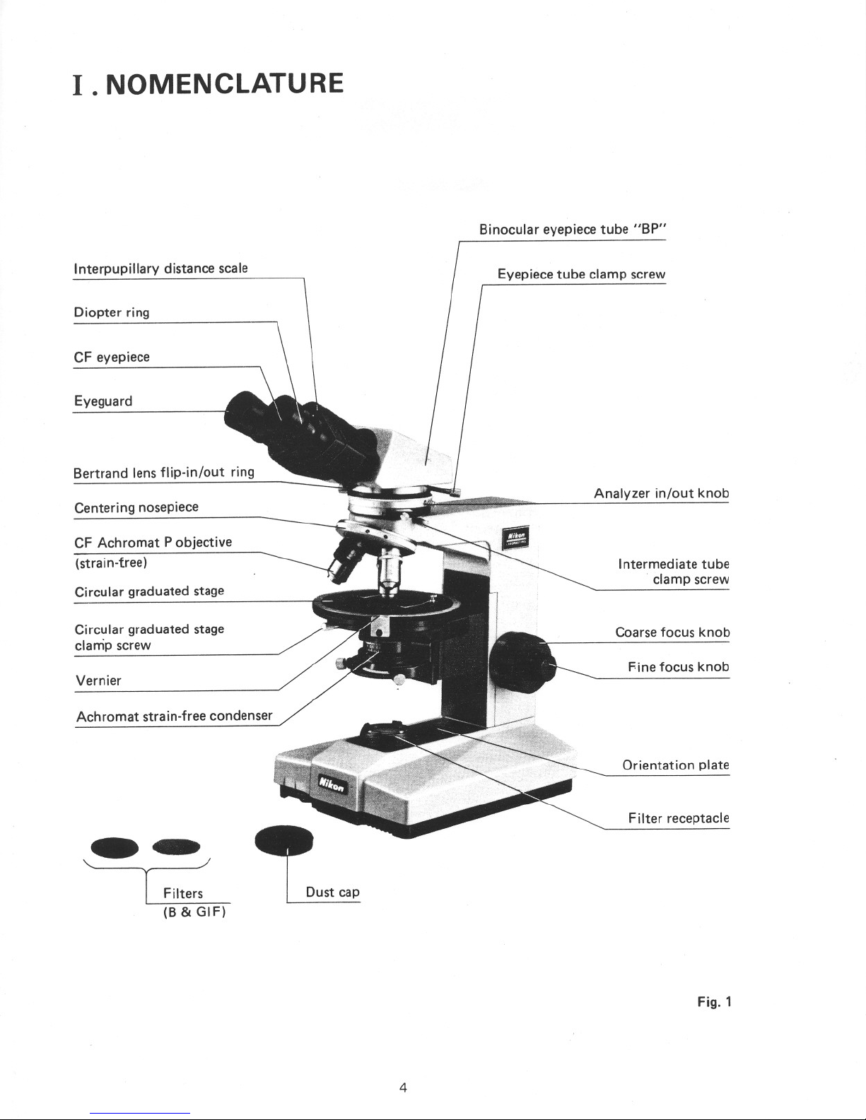
I.NOMENCLATURE
Binocular eyepiece tube "BP"
Interpupillary distance scale
Diopter ring
CF eyepiece
Eyeguard
Bertrand lens flip-in/out ring
Centering nosepiece
CF Achromat P objective
(strain-tree)
Circular graduated stage
Circular graduated stage
clamp screw
Vernier
Achromat strain-free condenser
Filters
(B& GIF)
Dust cap
4
Eyepiece tube clamp screw
Analyzer in/out knob
Intermediate tube
clamp screw
Coarse focus knob
Fine focus knob
Orientation plate
Filter receptacle
Fig. 1

Analyzer rotation ring
Intermediate tube "P"
Analyzer clamp screw
Condenser focus knob
Lamp socket
Field diaphragm
control ring
V-POL stand
5
Compensator slot
1/4
A & tint plate
Nosepiece centering screw
Specimen clip
Stage rotation clamp screw
Condenser centering screw
Condenser aperture
diaphragm control ring
Dia-polarizer
Condenser clamp screw
Field lens
Brightness control dial
(including power switch)
Fig.2
II. ASSEMBLY
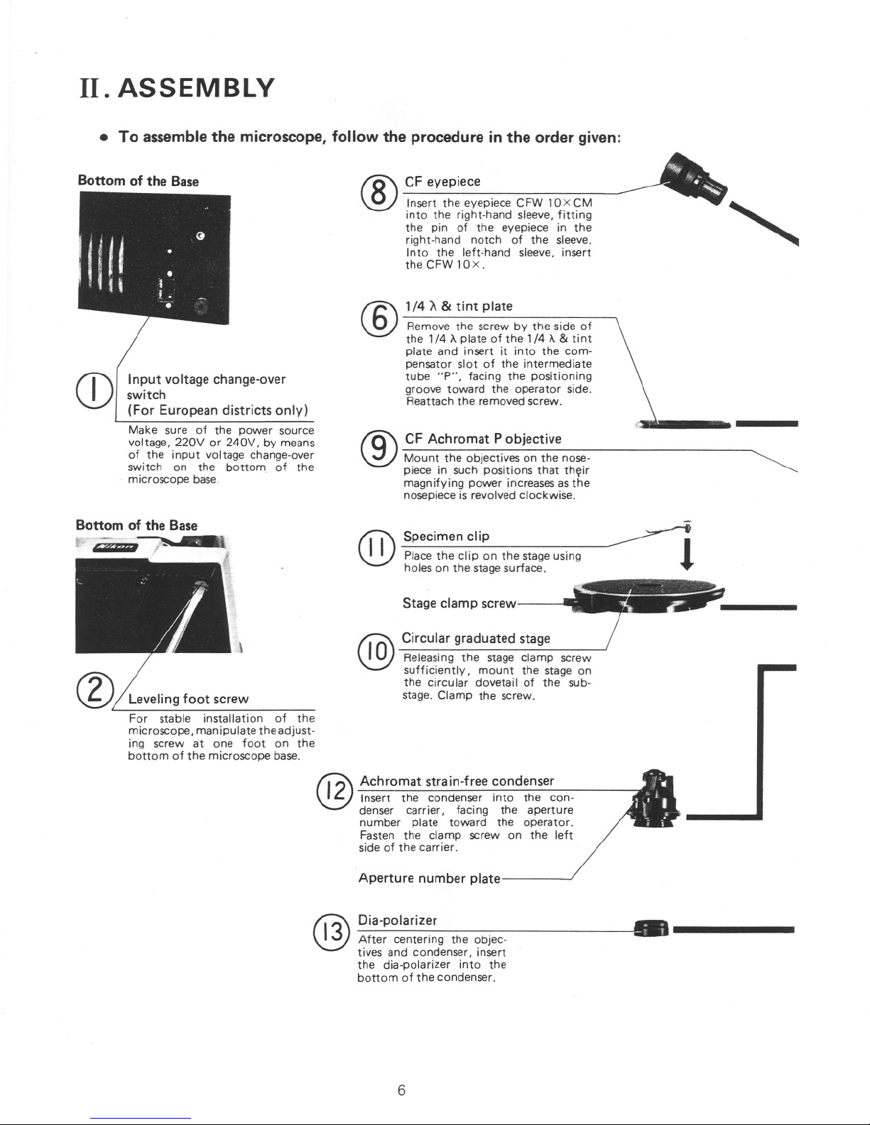
1/4 A & tint plate
Remove the screw by the side of
the 1/4
A plate of the 1/4 A & tint
plate and insert it into the com-
pensator slot of the intermediate
tube "P", facing the positioning
groove toward the operator side.
Reattach the removed screw.
®
®
CF Achromat P objective
Mount the objectives on the nose-
piece in such positions that thfilir
magnifying power increasesasthe
nosepiece is revolved clockwise.
Input voltage change-over
switch
(For European districts only)
Make sure of the power source
voltage, 220V or 240V, by means
of the input voltage change-over
switch on the bottom of the
microscope base_
• To assemble the microscope, follow the procedure in the order given:
--'
CF eyepiece _
®Insert the eyepiece CFW 10XCM- '"
into the right-hand sleeve, fitting
the pin of the eyepiece in the
right-hand notch of the sleeve.
Into the left-hand sleeve, insert
the CFW lOx.
Bottom of the Base
CD
@2 Achromat strain-free condenser
Insert the condenser into the con-
denser carrier, fad ng the aperture
number plate toward the operator.
Fasten the clamp screw on the left
side of the carrier.
Aperture number plate
•.----
Specimen clip
Place the clip on the stage using
holes on the stagesurface.
Stage clamp screw
Circular graduated stage
Releasing the stage clamp screw
sufficiently, mount the stage on
the circular dovetail of the sub-
stage. Clamp the screw.
Dia-polarizer
After centering the objec-
tives and condenser, insert
the dia-polarizer into the
bottom of the condenser.
@
@)
@
Leveling foot screw
For stable installation of the
microscope, manipulate the adjust-
ing screw at one foot on the
bottom of the microscope base.
6
•
---------. ?:=:
Y·POL stand
@T:.er
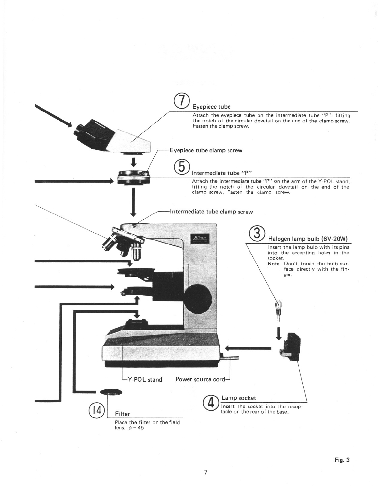
(]) Eyepiece tube
Attach the eyepiece tube on the intermediate tube "P", fitting
the notch of the circular dovetail on the end of the clamp screw.
Fasten the clamp screw.
Eyepiece tube clamp screw
®Intermediate tube "P"
Attach the intermediate tube "P" on the arm of the V-POL stand,
fitting the notch of the circular dovetai I on the end of the
clamp screw. Fasten the clamp screw.
Intermediate tube clamp screw
Halogen lamp bulb (6V-20W)
Insert the lamp bulb with its pins
into the accepting holes in the
socket.
Note Don't touch the bulb sur-
face directly with the fin-
ger.
Power source cord
t4'Lamp socket~ Insert the socket into the recep-
tacle on the rear of the base.
Place the filter on the field
lens.
<p = 45
Fig. 3
7
III. PREPARATION
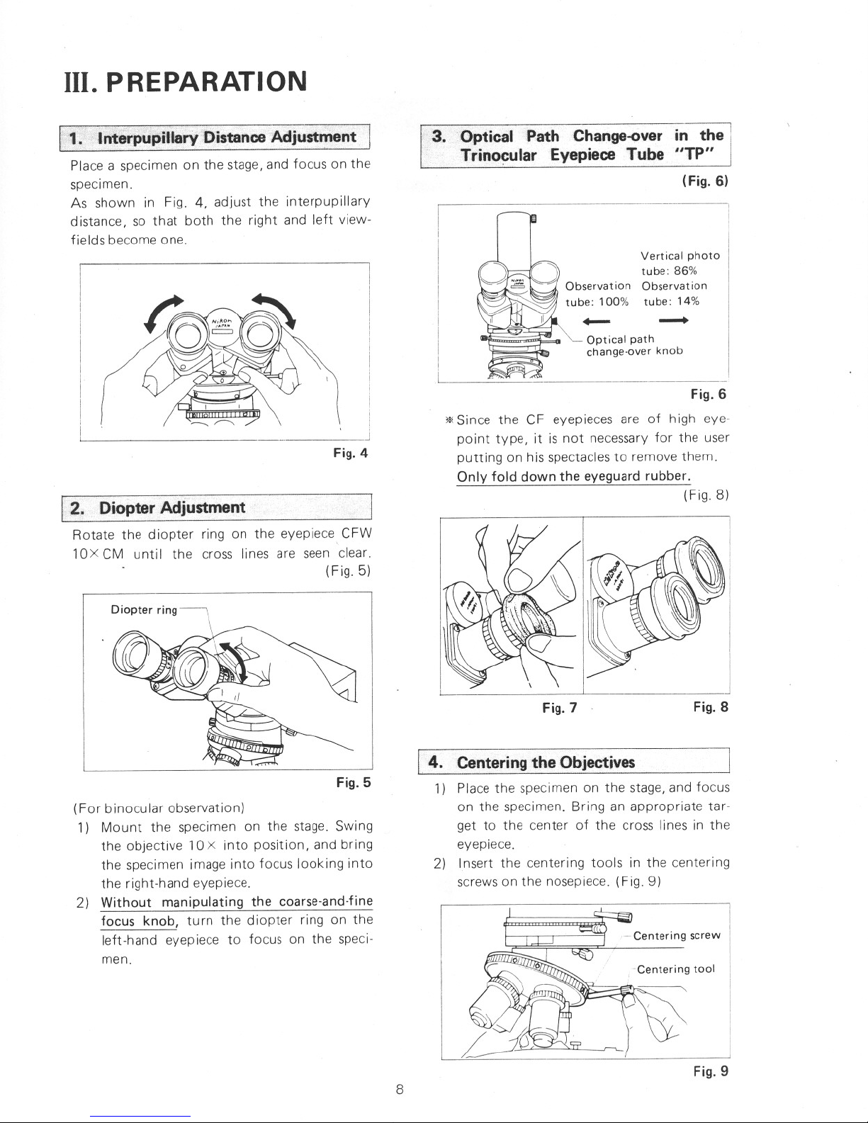
3.. Optical Path Change-over in the 1
Trinocular Eyepiece Tube "TP"
(Fig. 6)
Fig. 8
Vertical photo
tube: 86%
Observat ion
tube: 14%
Optical path
change-over knob
Fig. 7
Fig.6
'* Since the CF eyepieces are of high eye-
point type, it is not necessary for the user
putting on his spectacles to remove them.
Only fold down the eyeguard rubber.
(Fig.8)
I. 4. Centeringthe Objectives
1) Place the specimen on the stage, and focus
on the specimen. Bring an appropriate tar-
get to the center of the cross lines in the
eyepiece.
2) Insert the centering tools in the centering
screws on the nosepiece. (Fig. 9)
(For binocular observation)
1) Mount the specimen on the stage. Swing
the objective 10 x into position, and bring
the specimen image into focus looking into
the right-hand eyepiece.
2) Without manipulating the coarse-and-fine
focus knob, turn the diopter ring on the
left-hand eyepiece to focus on the speci-
men.
Fig. 5
____ J
Fig. 4
2. Diopter Adjustment
Rotate the diopter ring on the eyepiece CFW
10X CM until the cross lines are seen clear.
(Fig.5)
1. ·Interpupiflary DistanceAdjustment I
Place a specimen on the stage, and focus on the
specimen.
As shown in Fig. 4, adjust the interpupillary
distance, so that both the right and left view-
fields become one.
Fig.9
8
 Loading...