

Nikon LABOPHOT2-POL Instructions Manual
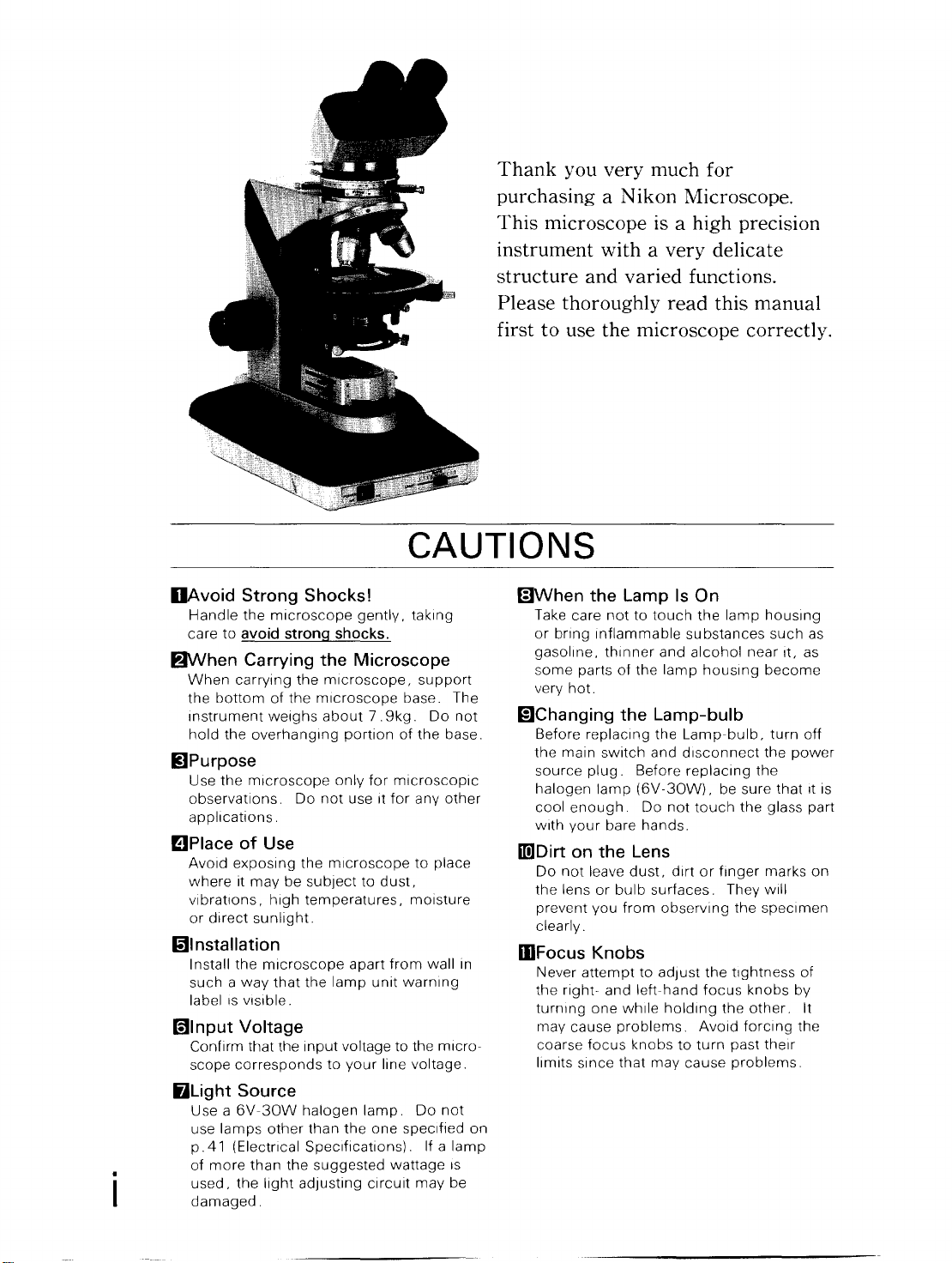
Thank you very much for
purchasing a N ikon Microscope.
This microscope is a high precision
instrument with a very delicate
structure and varied functions.
Please thoroughly read this manual
first to use the microscope correctly.
CAUTIONS
DAvoid Strong Shocks!
Handle
care
the
microscope
to
avoid strong shocks.
gently.
taking
fJWhen Carrying the Microscope
When
carrying
the
bottom
Instrument
hold
the
the
microscope,
of
the
microscope
weighs
overhanging
about
7.
portion
support
base. The
9kg.
Do
of
the
IiJPurpose
Use
the
microscope
observations.
applications.
Do
not
only
use It
for
microscopIc
for
any
mPlace of Use
Avoid
exposing
where
it
vibrations,
or
direct
may
be
high
sunlight.
the
microscope
subject
temperatures,
to
dust,
to
place
mOisture
mlnstallation
I nstall
the
such a way
label
IS
vIsible.
microscope
that
the
apart
lamp
unit
from
warning
wall
G)lnput Voltage
Confirm that the
scope
corresponds
BLight
Source
Use a
6V~30W
use
lamps
p.41
(Electrical
of
more
used,
the
damaged.
than
Input
halogen
other
than
Specifications).
the
suggested
light
adjusting
voltage to the
to
your
line
lamp
the
one
wattage
circuit
mlcro~
voltage.
Do
specified
If a
may
not
base.
other
In
not
lamp
IS
be
(;]When the Lamp
Take care
or
bring
gasoline.
some
very
not
Inflammable
thinner
parts
hot.
of
to
the
mChanging the Lamp-bulb
Before replaCing the
the
main
switch
source
halogen
cool
With
mJDirt
Do
the
prevent
clearly.
plug.
enough
your
on
not
leave
lens
or
you
Before replaCing
lamp
(6V~30W),
bare
the
Lens
dust,
bulb
from
IDFocus Knobs
Never
on
the
rlght~
turning
may
cause
coarse
limits
attempt
focus
since
to
and
left~hand
one
while
problems.
knobs
that
Is
On
touch
the
substances
and
alcohol
lamp
hOUSing
Lamp~bulb,
and
disconnect
Do
not
touch
hands.
dirt
or
surfaces.
obserVing the
adjust
the
focus
holding
Avoid
to
turn
may
cause
lamp
housing
near
become
the
the
be sure
the
finger
marks
They
will
specimen
tightness
knobs
the
other.
forCing
past
their
problems.
such
as
It, as
turn
off
power
that
It is
glass part
on
of
by
It
the
CONTENTS
I
.NOMENCLATURE
························1
II.ASSEMBLY····································4
III. MiCROSCOPy··························· 11
N .OPERATIONS IN DETAIL .........
1 . Orientation
2.
Focusing and Centering the
Bertrand
3.
SWing
Condenser
4.1
!4A
5.
Centering the Objectives
6.
Stage Rotation .... · ........................
7.
Focusing
8.
Centering the Condenser
9.
Use
Diaphragm
of
the Dia·polarizer
Lens'
.............................
Out
the
Top
Lens of the
.................................
& Tint Plate
....................................
of
Condenser Aperture
........................
.................................
...............
...............
......
..
·19
·20
17
17
1 8
19
20
21
22
23
10.
Use
of
Field
Diaphragm
..............
1 1 . Optical Path Change· Over ........ ·
12
. Interpupillary
13.
Diopter
14.
Oil Immersion
15.
Brightness
Adjustment
16.
Objectives and Eyepieces
DistanceAdjustment·25
Adjustment
and
...............................
.....................
Manipulation
Contrast
........
............
V .OPTIONAL ACCESSORIES ......
1 .
Senarmont
2.
Quartz
3.
Pin
Hole Eyepiece
4.
Attachable
5. Universal Epi-illuminator
Compensator
Wedge
Mechanical
..............
..............................
........................
Stage"
.......
...............
VI.TROUBLESHOOTING ...............
ELECTRICAL SPECIFICATIONS
...
..
·30
·24
·24
25
·26
27
29
30
31
32
32
33
35
41
CARE
DCleaning the
To clean the lens surfaces. remove
uSing a soft brush
removing
soft
cotton
moistened
lightly
(methyl alcohol
cleaning the objectives
use
only xylene.
cleaning the surface
of
the eyepiece
of
the
Ultra-Wide
Observe sufficient caution
alcohol
and the ON-OFF
sWitch.
and xylene (they are
finger
cloth,
Lenses
or
marks
lens tissue,
With pure alcohol
or
ethyl
Do
tube
Eyepiece Tube
of
AND
gauze. Only
or
grease, use a
or
alcohol).
of
immersion
not
use xylene
of
the entrance lens
or
the prism surface
In
handling
inflammable),
the
power
source
gauze
"UW".
fjCleaning the Painted Surfaces
Avoid the
example,
cleaning the painted surfaces and plastic
parts
you use the Silicon
of
the
use
of
any organic solvent (for
thinner,
ether, alcohol)
instrument.
cloth.
We
for
recommend
8lNever Attempt to Dismantle!
Never attempt to dismantle the
instrument
functions.
because you may
impair
MAINTENANCE
dust
when
For
for
the
oil
mWhen
When
with
it
fungus.
that
In
desiccant.
GiPeriodic Checking
To maintain the best
Instrument,
Instrument
details
authOrIZed Nikon
* Please note
"Any defects or damage directly or
indirectly caused by the
unauthorized replacement parts
performed
will void the warranty.
Not
in
Use
not
in use, cover the
the accessory vinyl cover, and store
in
a place free from moisture and
It
is
especially
the objectives and eyepieces be kept
an
airtight
container
we
recommend
be periodically
of
this check,
as
per
by
unauthorized personnel"
recommended
containing
performance
checked.
contact
distributor.)
your
N ikon
use
Instrument
of
the
that the
(For
your
warranty.
of
and/or
. .
II

I
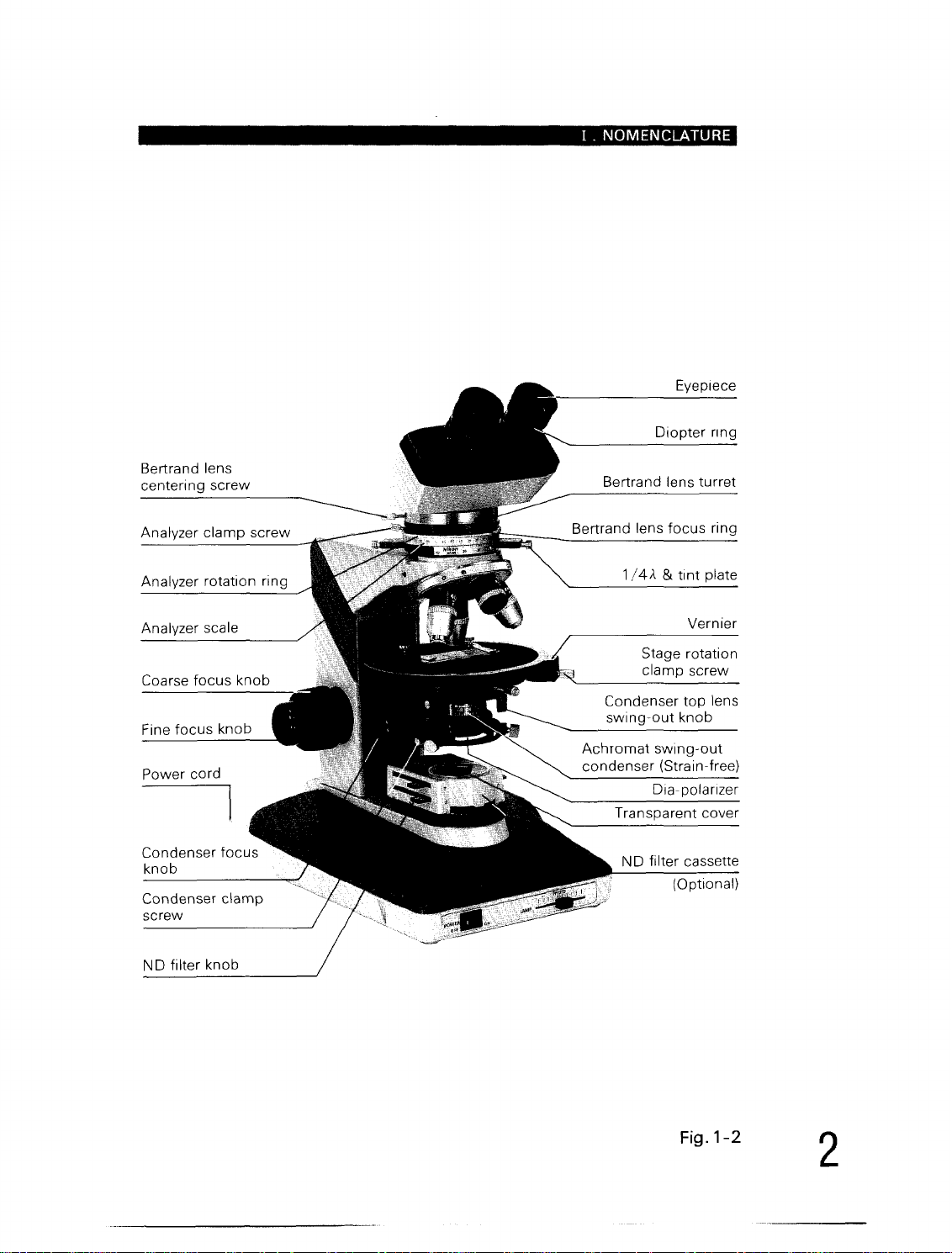
I . NOMENCLATURE
NOMENCLATURE
•
Intermediate
Nosepiece
screw
Centering revolving
nosepiece
CF
Achromat
(Stra i n
Specimen
Circular
stage
Stage
Condenser
screw
Condenser
diaphragm
diaphragm
Field
control
tube
centering
-free)
clip
graduated
clamp
centering
aperture
control
ring
P objective
screw
ring
Binocular
eyepiece
Eyepiece
clamp
Bertrand lens
centering
Analyzer
Intermediate
clamp
screw
Revolving nosepiece
clamp
screw
Coarse-focus
adjustment
Fine-focus
Lamp
tube
tube
screw
screw
knob
tube
torque
ring
scale
hOUSing
Arm
rest
1
Power
switch
Brightness
adjuster
Fig.1-1
II.
II.
ASSEMBLY
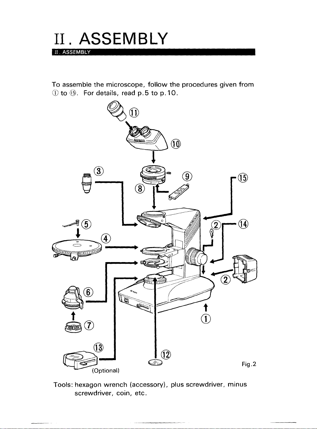
To
assemble
CD
to
ASSEMBLY
the
@.
For details, read
microscope,
follow
p.5
%@
to
p.
the
procedures
10.
given
from
a®---...6
t
~CV
@
Fig.2
~Ptionall
Tools: hexagon
screwdriver,
wrench
coin,
(accessory), plus
etc.
screwdriver,
minus
I.
NOMENCLATURE
Eyepiece
Bertrand lens
centering screw
Analyzer
Analyzer rotation ring
Analyzer scale
Coarse
Fine
Power cord
Condenser
knob
Condenser
screw
clamp
focus
focus
screw
knob
knob
focus
clamp
Diopter
Bertrand lens turret
Bertrand
lens
1/4'" & tint
Stage rotation
clamp screw
Condenser
swing~out
ring
focus
ring
plate
Vernier
top
lens
knob
(Optional)
N D
filter knob
Fig.1-2
2
II.
ASSEMBLY
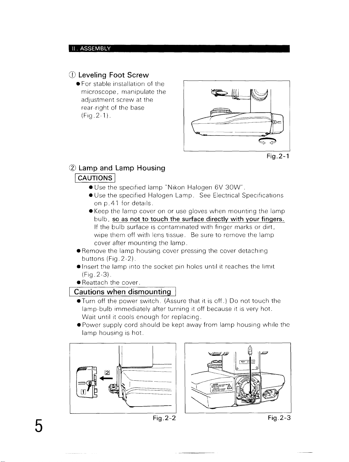
CD
Leveling Foot Screw
•
For
stable installation
microscope,
adjustment
rear-right
(Fig.2-1).
(2)
Lamp and Lamp Housing
manipulate
screw
of
the
at
base
of
the
the
the
I CAUTIONS I
• Use
the
specified
e Use
the
specified
on
p.4 1 tor
• Keep
• Remove
buttons
elnsert
(Fig.
• Reattach
bulb,
If
the
wipe
cover
the
2-3).
the
so
bulb
them
after
the
(Fig.
lamp
the
lamp
as
surface
off
mounting
lamp
2-2).
cover.
Cautions when dismounting
• Turn
•
oft
the
lamp-bulb
Wait
until it
Power
lamp
supply
hOUSing
power
Immediately
cools
cord
is
lamp
Halogen
details .
cover
not to touch the surface directly with your fingers.
IS
with
lens
housing
Into
the
socket
switch.
after
enough
should
hot.
"Nikon
on
or
contaminated
tissue.
the
cover
(Assure
turning
for
be kept
Halogen
Lamp.
use gloves
Be sure
lamp.
pressing
pin holes
that
It
replacing.
away
6V
30W".
See Electrical
when
mounting
with
finger
to
remove
the
cover
until
it reaches
It is
off.)
Do
off
because
trom
lamp
Specifications
the
marks
It is very
or
the
lamp
detaching
the
not
touch
housing
dirt,
limit
hot.
while
Fig.2-1
lamp
the
the
5
Fig.2-2
Fig.2-3
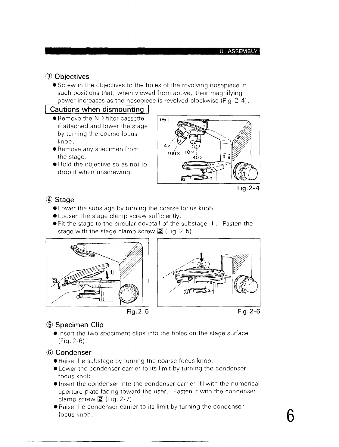
Q)
Objectives
•
Screw
such positions
power
in the objectives
that,
when
increases
as
the nosepiece
to
the holes
viewed
Cautions when dismounting I
• Remove
If attached and
by
knob.
• Remove any
the
• Hold
drop
the
turning
stage.
the
it
when
NO filter cassette
lower
the
the
coarse
specimen
objective so
unscrewing.
focus
as
stage
from
not
® Stage
•
Lower
• Loosen
• Fit
stage
the
the
the
stage to the
with
substage by
stage
clamp
circular
the
stage
clamp
turning
screw
dovetail
screw ~ (Fig.
from
is
(Ex.)
to
the coarse
sufficiently.
II.
of
the revolving nosepiece in
above,
revolved
of
the
their
clockwise
focus
2-5).
knob.
substage
magnifying
(Fig.
00.
Fasten
ASSEMBLY
2-4).
Fig.2-4
the
@ Specimen Clip
.Insert
(Fig.
the
2-6).
two
speciment
® Condenser
• Raise the substage by
•
Lower
focus
• Insert
aperture plate
clamp
• Raise
focus
the
condenser
knob
.
the
condenser
facing
screw ~ (Fig.
the
condenser
knob.
Fig.2-5
clips into
turning
carrier
into
the
toward
2-7).
carrier
the
the coarse
to
its
limit
condenser
the
user. Fasten it
to
its
limit
holes on
focus
by
turning
carrier
by
turning
the
stage surface
knob.
the
condenser
00
with
the
with
the
the
condenser
Fig.2-6
numerical
condenser
6
II.
ASSEMBLY
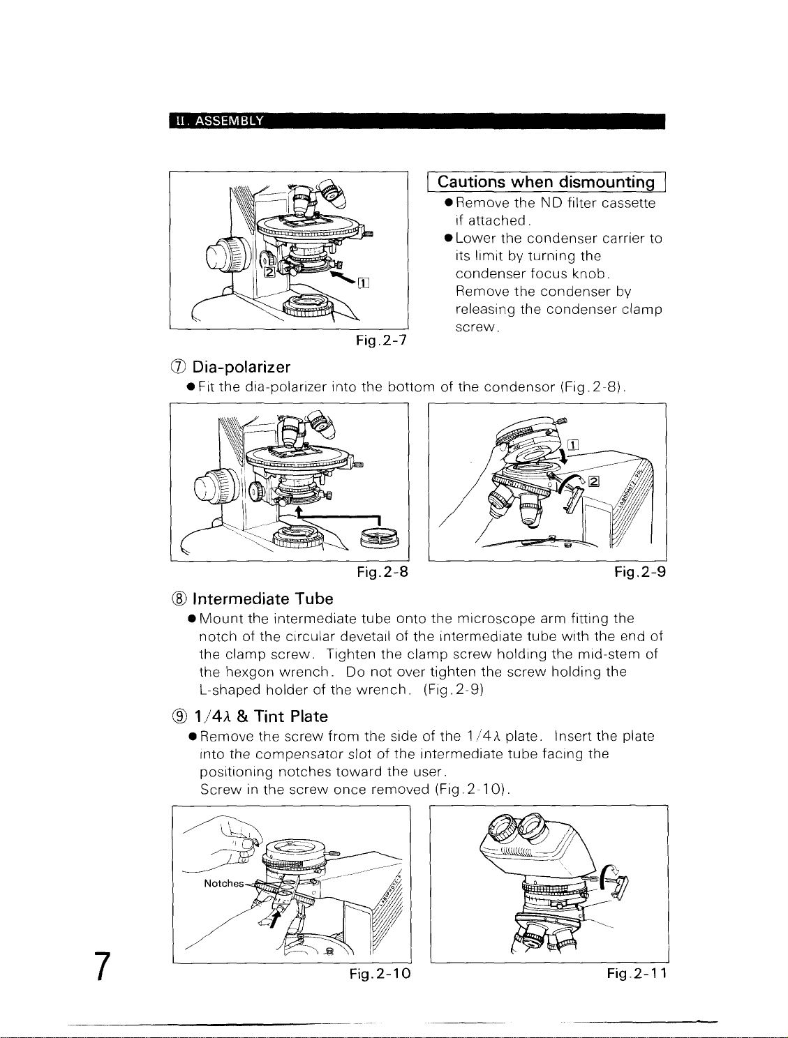
(J)
Dia-polarizer
• Fit
the
dia-polarizer
into
Fig.2-7
the
bottom
Fig.2-8
Cautions
• Remove
if attached .
•
Lower
its
limit
condenser
Remove
releasing
screw.
of
the
condensor
when
the
the
by
the
dismounting
N D filter cassette
condenser
turning
focus
condenser
the
condenser
(Fig.
carrier to
the
knob.
by
clamp
2-8).
Fig.2-9
7
@ Intermediate Tube
•
Mount
notch
the
the
L-shaped
the
of
the
clamp
hexgon
intermediate
circular
screw.
wrench.
holder
of
® 1 /4A & Tint Plate
• Remove
Into the
positioning
Screw
the
screw
compensator
notches
in
the
screw
tube
devetail
Tighten
Do
the
wrench.
from
the side
slot
toward
once
Fig.2-10
onto
of
the
the
clamp
not
over
of
the
the user.
removed
the
microscope
intermediate
screw
tighten
(Fig.
of
intermediate
(Fig.
the
the
2-9)
1/4
A plate. I nsert
2-10).
tube
holding
screw
tube
arm
fitting
with
the
holding
facing
the
the end
mid-stem
the
the
plate
the
Fig.2-11
of
of
@ Binocular Eyepiece Tube
e
Mount
of
clamp
(See @ and
the eyepiece
the
circular
screw.
dovetail
Tighten
Fig.2-11
tube
of
the
.)
onto
the
clamp
I Cautions when clamping I
eTighten
hexagonal
optical-path
malfunctioned.
QJ)
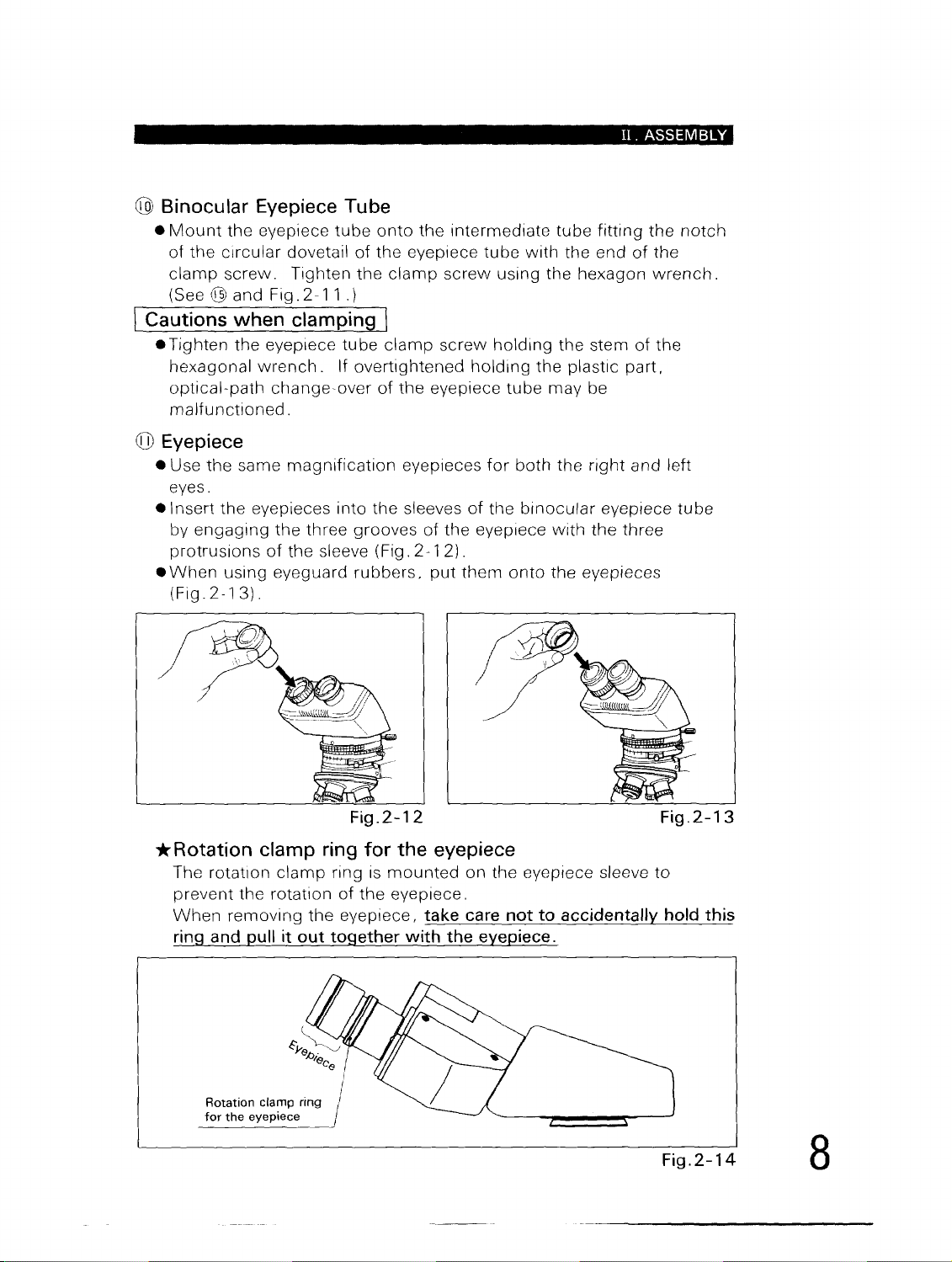
Eyepiece
e Use
eyes.
elnsert
by
protrusions
e
When
(Fig.2-13).
the eyepiece
wrench.
change-over
the
same
the
eyepieces into
engaging
using eyeguard
the
of
tube
clamp
If overtightened
of
magnification
the
three grooves
the sleeve (Fig.
rubbers,
the
intermediate
eyepiece
screw
screw
the
eyepiece
eyepieces
sleeves
of
the
2-12).
put
them
tube
tube
with
the end
using the hexagon
holding
holding
for
of
the
eyepiece
the stem
the
tube
may be
both
the
binocular
with
onto
the eyepieces
plastic
II.
ASSEMBLY
fitting
right and left
the
the
of
the
wrench.
of
the
part,
eyepiece
three
notch
tube
*Rotation
The rotation
prevent the rotation
When
ring
Rotation
for
clamp ring for the eyepiece
clamp
removing
and
pull
it out together with the eyepiece.
clamp ring
the
eyepiece
Fig.2-12
ring
is
mounted
of
the
eyepiece.
the
eyepiece, take care not to accidentally hold this
on the eyepiece sleeve
Fig.2-13
to
Fig.2-14
8
II.
ASSEMBLY
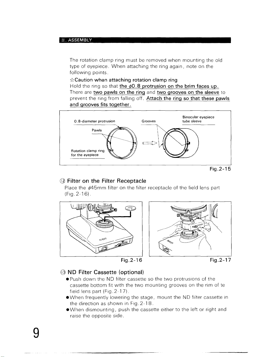
The rotation
type
of
following
uCaution
Hold
the ring so
There are
prevent
clamp
eyepiece.
ring
When
must
be removed
attaching
points.
when attaching rotation clamp
that
the
¢O.8
protrusion
two
the
pawls
ring
from
on
the
failing
ring
off.
and grooves fits together.
O.
8-diameter
Rotation
for
the
Pawls
clamp
eyepiece
protrusion
ring
Grooves
@ Filter on the Filter Receptacle
Place the
(Fig.
2-16).
¢45mm
filter on the filter receptacle
when
the ring
on
and
two
grooves
Attach the
mounting
again,
note on the
ring
the brim faces
on
ring
so
that these pawls
Binocular
tube
sleeve
of
the
field lens part
the old
up.
the sleeve
eyepiece
Fig.2-15
to
9
Fig.2-16
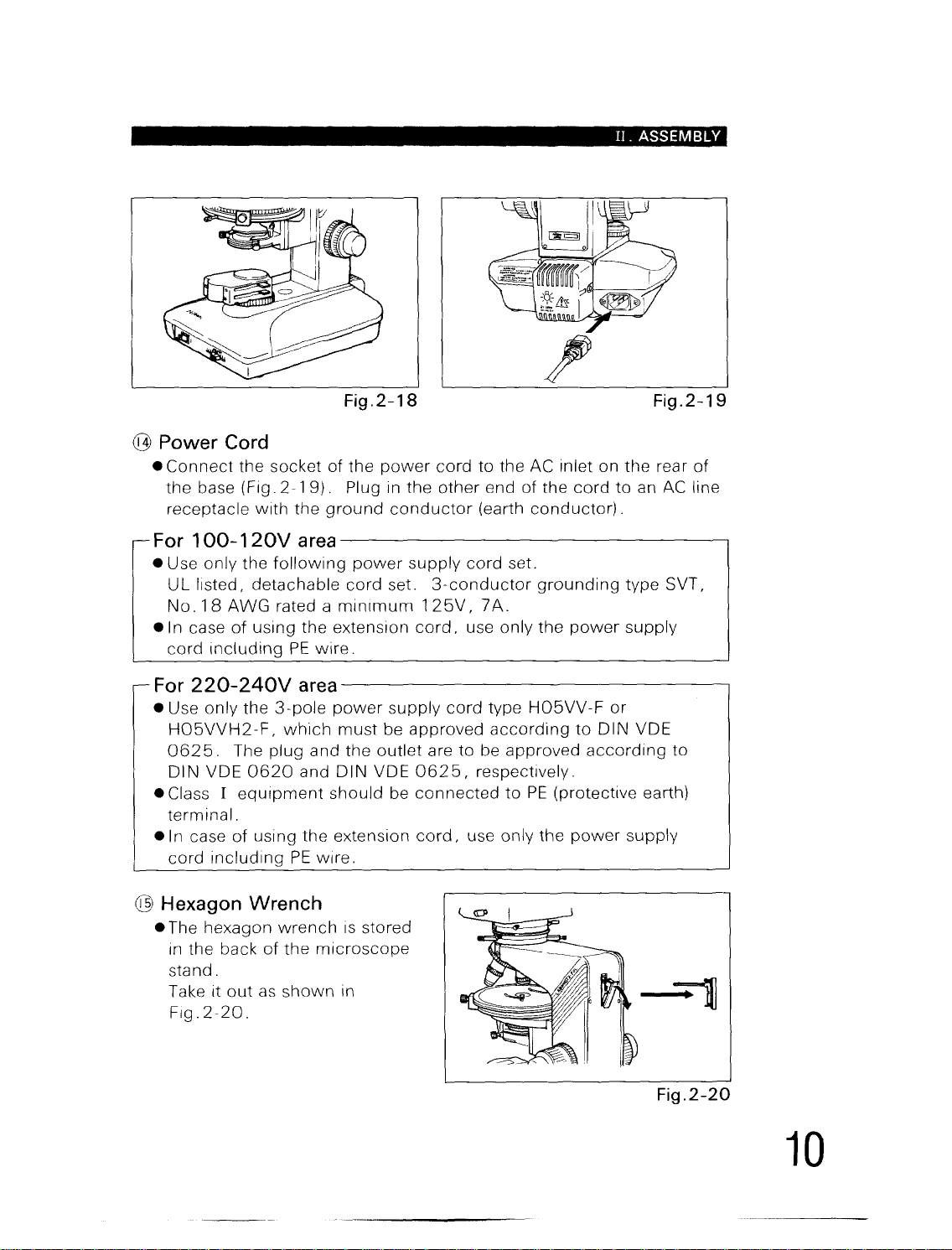
@ N D Filter Cassette (optional)
• Push
•
•
down
cassette
field lens
When
the
When
frequently
direction
dismounting,
raise the
the
ND
bottom
part
(Fig.
as
opposite
filter cassette so the
fit
with
the
two
2-17)
.
lowering
shown
the stage,
in Fig.
2-18
push the cassette either
side.
two
mounting
mount
.
Fig.2-17
protrusions
of
the
grooves on the rim
the
ND
filter cassette
to
the
left
or
right
of
te
in
and
II.
ASSEMBLY
Fig.2-18
Fig.2-19
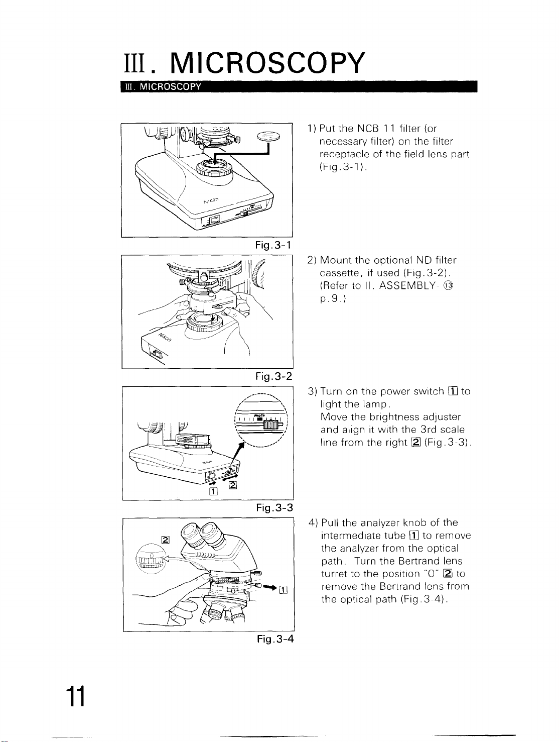
@ Power Cord
e
Connect
the
receptacle
For
e Use only the
U L
No.
el
n case
cord
For220-240Varea------------------------------~
e Use only the
H05VVH2-F,
0625.
DIN
e Class I
terminal.
eln
cord
the socket of
base (Fig.
100-120Varea------------------------------~
listed, detachable cord set.
18
AWG
including
VDE
case
including
2-19).
with
the
following
rated a
of
using
PE
3-pole
which
The plug and the
0620
equipment
of
using
PE
the
power
Plug in
ground
minimum 1 25V,
the
extension
wire.
power
must
and DIN VDE
should
the
extension
wire.
conductor
power
supply
be approved
outlet
be
cord
the
other
supply
cord,
0625,
connected
cord,
cord set.
3-conductor
use only
cord
are
to
use only the
to
the AC inlet on
end
of
the
(earth
be approved
respectively.
conductor).
grounding
7 A.
the
type
H05VV-F
according
to
PE
(protective earth)
cord
to an AC line
power
or
to
DIN VDE
according
power
the
rear
of
type SVT,
supply
to
supply
@ Hexagon Wrench
e The hexagon
in
the back
sta nd .
Take it
Flg.2-20.
out
wrench
of
the
as
shown
IS stored
microscope
in
Fig.2-20
10
III.
III. MICROSCOPY
MICROSCOPY
Fig.3-1
Fig.3-2
-""'
...
-----
....
;,,;
, '
" \
:~I
II~/
,
'\
f'MoTe ,
1) Put
2)
3) Turn on
the
NCB
11
necessary
receptacle
(Flg.3-1).
Mount
cassette, if used (Fig.
(Refer to II.
p.9.)
light
Move
and
line
from
the
the
the
lamp.
the
align it
the
filter) on
of
the
optional
ASSEMBLY-
power
brightness
with
right ~ (Fig.
filter
(or
the
filter
field lens part
ND
filter
3-2).
@
switch
the
rn
adjuster
3rd
scale
3-3).
to
11
Fig.3-3
Fig.3-4
4) Pull
the
intermediate
the
analyzer
path.
turret
remove
the
optical
analyzer
Turn
to
the
the
path
knob
of
tube
rn
to
remove
from
the
optical
the
Bertrand lens
position
Bertrand lens
"0" ~ to
(Fig.3-4).
the
from
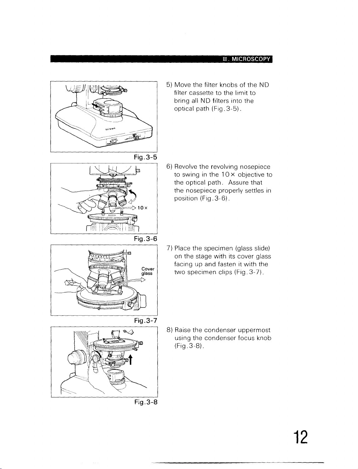
Fig.3-5
Fig.3-6
Ill.
MICROSCOPY
5)
Move the filter knobs
filter cassette
bring all
optical path (Fig.
6) Revolve the revolving nosepiece
to
swing in
the optical
the nosepiece properly settles
position (Fig.
7} Place the specimen (glass slide)
on the stage
facing
two
up
specimen clips (Fig.
to
ND
filters into the
the
path.
3-6).
with
and fasten it
of
the
the
limit
to
3-5).
10
x objective
Assure
its cover glass
that
with
3-7).
N D
to
in
the
Fig.3-7
Fig.3-8
8} Raise the
using the
3-8).
(Fig.
condenser
condenser
uppermost
focus
knob
12
 Loading...