

Page 1
Nikon
Biological Microscope
INSTRUCTIONS
NIKON CORPORATION
Page 2
CAUTIONS
oAvoid sharp knocks!
Handle the microscope gently, taking care
to avoid sharp knocks.
8When carrying the microscope
When carrying the microscope, hold its arm
with one hand, supporting the bottom of
the microscope base with the other. The
instrument weighs about 8 kg.
oPlace for using
Avoid the use of the microscope in a dusty
place, where it is subject to vibrations or
exposed to high temperatures, moisture or
direct sunlight.
e Light source
Usehalogen lamp 6V - 20W.
o In lighting the lamp
Take care not to touch the rear cover of
the lamp being lighted, and don't bring
inflammable substances such as gasoline,
thinner, and alcohol near to the cover, asit
may take a high temperature while the
lamp is being lighted.
o Focus knobs
Never attempt to adjust the tightness of
the right- and lefthand focus knob by turn-
ing the one, while holding the other in this
model microscope, because of causing
disorder.
o Exchanging the lamp bulb and fuse
Before replacing the lamp bulb (6V - 20W)
or fuse, turn OFF the power switch and
disconnect the plug of the power source
cord.
In such cases as of replacement, do not
touch the lamp bulb with bare hands,
immediately after putting out the lamp.
oDirt on the lens
Do not leave dust, dirt or finger marks on
the lens surfaces. They will prevent you
from clear observation of the specimen
image.
2
Page 3
CARE AND MAINTENANCE
CONTENTS
oCleaning the lenses
T6 clean the lens surfaces, remove dust
using a soft brush or gauze. Only for
removing finger marks or grease, should
soft cotton cloth, lens tissue or gauze
Iightly moistened with absolute alcohol
(ethyle alcohol or methyl alcohol) be used.
For cleaning the objectives and immersion
oil use only xylene.
For cleaning the surface of the entrance
lens of the eyepiece tube and the prism
surface of the Trinocular Eyepiece Tube
"T" or the Ultra Wide Eyepiece Tube
"UW", useabsolute alcohol.
Observe sufficient caution in handling
alcohol and xylene.
f)Cleaning the painted surfaces
Avoid the use of any organic solvent (for
example, thinner, ether, alcohol, xylene
etc.) for cleaning the painted surfaces and
plastic parts of the instrument.
8Never attempt to dismantle!
Never attempt to dismantle the instrument
so as to avoid the possibility of impairing
the operational efficiency and accuracy.
NOMENCLATURE .
I.
II. ASSEMB LY .
MICROSCOPY .
III.
1. Operating Procedure .
2. Manipulation of Each Element
1) Interpupillary distance
adjustment .
2) Diopter adjustment .
3) Optical path change-over in the
trinocular eyepiece tube 9
4) Centering the condenser lens 10
5) Useof condenser aperture
diaphragm 10
6) Use of field diaphragm 11
7) Focusing 11
IV. OPTICAL SYSTEM .
V. PHOTOMICROGRAPHY 16
VI. USE OF THE ACCESSORIES 19
VII. TROUBLE SHOOTING TABLE 21
1. Optical 21
2. Manipulation 22
3. Electrical 23
4. Photomicrography 23
ELECTRIC SPECIFICATIONS
12
27
4
6
8
8
9
9
9
oWhen not in use
When not in use, cover the instrument with
the accessory vinyl cover, and store it in a
place free from moisture and fungus.
It is especially recommended that the
objectives and eyepieces be kept in an air-
tight container containing desiccant.
oPeriodical checking
To maintain the performance of the instru-
ment, we recommend to check the instru-
ment periodically. (For detai Is of this
check, contact our agency.)
3
Page 4
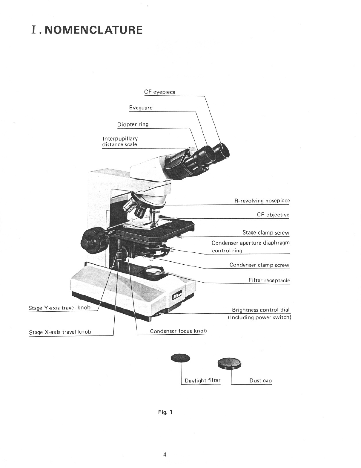
I. NOMENCLATURE
Diopter ring
Interpupillary
distance scale
CF eyepiece
Eyeguard
R-revolving nosepiece
Stage Y-axis travel knob
Stage X-axis travel knob
Condenser focus knob
Daylight filter
CF objective
Stage clamp screw
Condenser aperture diaphragm
control ring
Condenser clamp screw
Filter receptacle
Brightness control dial
(Including power switch)
Dust cap
Fig. 1
4
Page 5
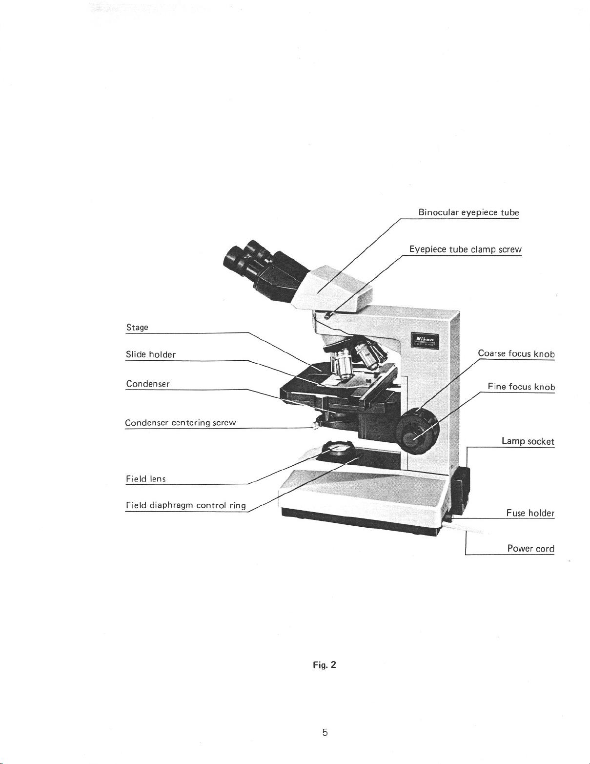
Stage
Binocular eyepiece tube
Eyepiece tube clamp screw
Slide holder
Condenser
Condenser centering screw
Field lens
Field diaphragm control ring
Coarse focus knob
Fine focus knob
Lamp socket
Fuse holder
Power cord
Fig. 2
5
Page 6
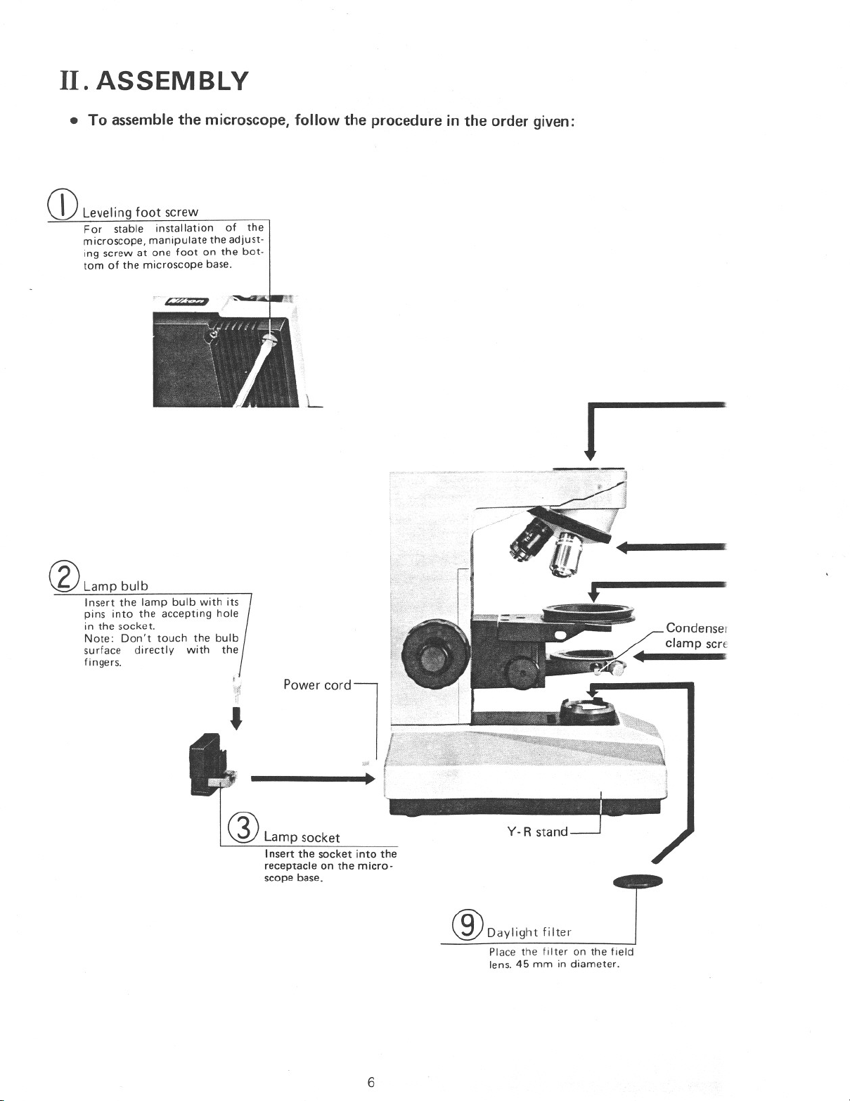
II. ASSEMBLY
• To assemble the microscope, follow the procedure in the order given:
Q)Leveling foot screw
For stable installation of the
microscope, manipulate the adjust-
ing screw at one foot on the bot-
tom of the microscope base.
L
J
®Lamp bulb
Insert the lamp bulb with its
pins into the accepting hole
in the socket.
Note: Don't touch the bulb
surface directly with the
fingers.
,
Pow" C",dl
Q) Lamp socket
Insert the socket into the
receptacle on the micro-
scope base.
/
I
!
iW
•
®Daylight filter
Place the filter on the field
lens. 45 mm in diameter.
6
Page 7
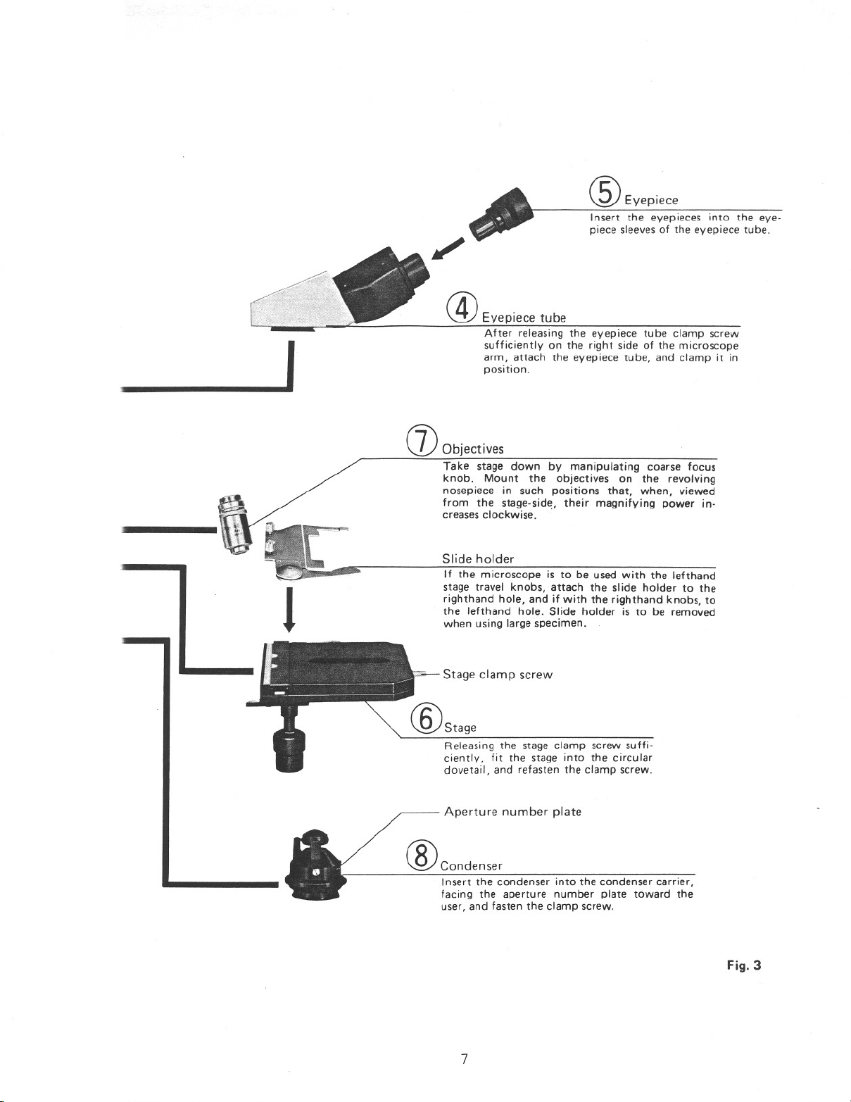
-----------
®EyepieCe
Insert the eyepieces into the eye-
piece sleevesof the eyepiece tube.
/
@Eyepiece tube
After releasing the eyepiece tube clamp screw
arm, attach the eyepiece tube, and clamp it in
position.
I sufficiently on the right side of the microscope
(]) Objectives
Take stage down by manipulating coarse focus
knob. Mount the objectives on the revolving
nosepiece in such positions that, when, viewed
from the stage-side, their magnifying power in-
creasesclockwise ..
Slide holder
If the microscope is to be used with the lefthand
stage travel knobs, attach the slide holder to the
righthand hole, and if with the righthand knobs, to
the lefthand hole. Slide holder is to be removed
J
when using large specimen.
,,,j.- Stage clamp screw
Releasing the stage clamp screw suffi-
ciently, fit the stage into the circular
dovetail, and refasten the clamp screw.
Aperture number plate
®condenser
Insert the condenser into the condenser carrier,
facing the aperture number plate toward the
user, and fasten the clamp screw.
7
Fig.3
Page 8
III. MICROSCOPY
I 1.~.,Op~rating~rocedure
1) Turn the brightness control dial (including power
switch) to ON and set the scaleon the dial to 4.
2) Remove the dust cap and place the daylight filter
onto the field lens.
3) Place the specimen on the stage and swing the
10x objective into position. Focus on specimen.
4) Adjust the interpupillary distance and diopter.
(Refer to P.9)
5) Carry out the centering procedure for the con-
denser. (Refer to P: 10)
6) Swi~g in the objective to be used and ~efocuson
specimen.
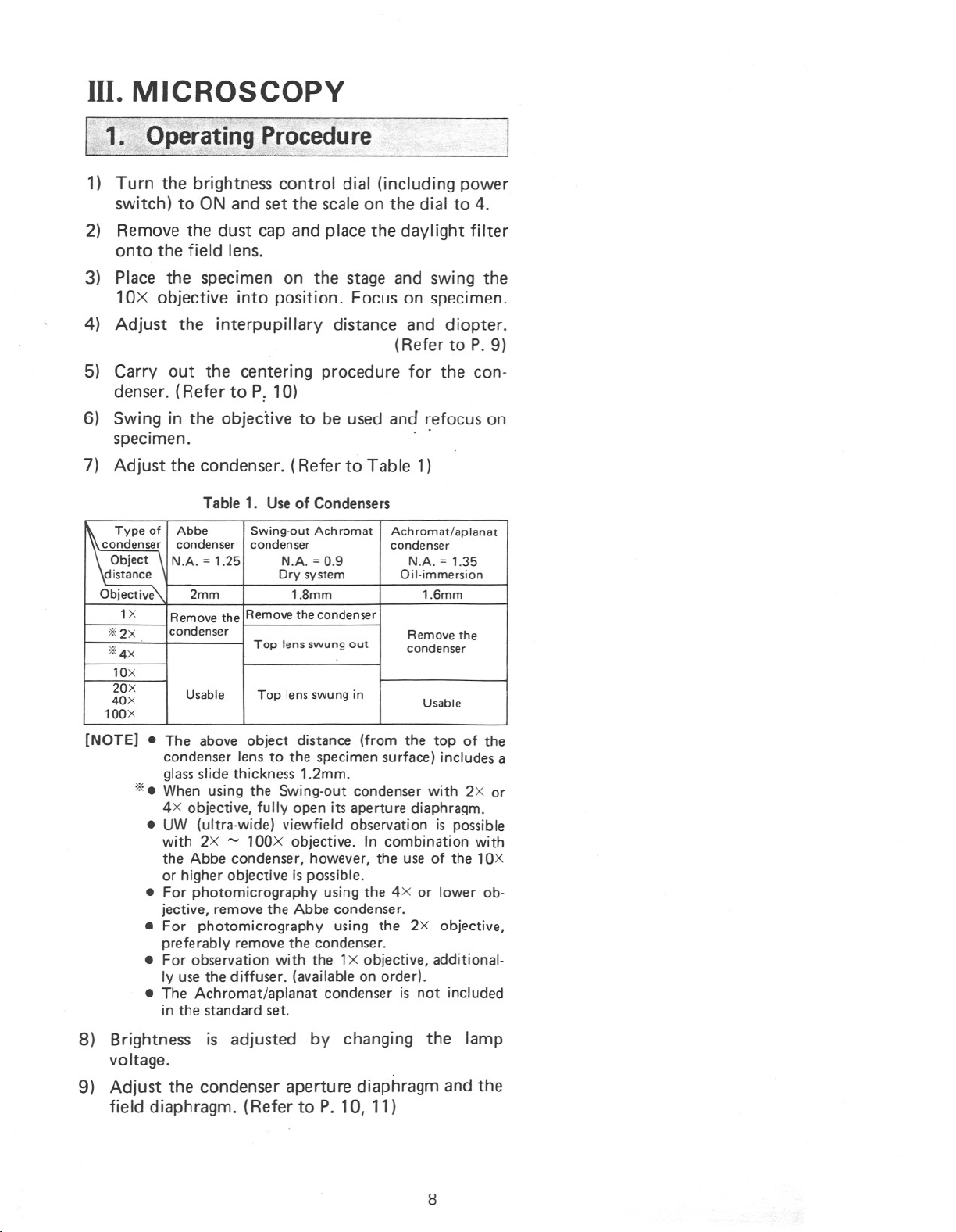
7) Adjust the condenser. (Refer to Table 1)
Table 1. Useof Condensers
\ Type of
20X
Remove the
Remove the condenser
condenser
condenser
condenser condenser
Abbe
Top lens swung in
Swing-out Achromat
2mm
NA = 1.25
Usable
Top lens swung out
NA = 1.35
1.8mm1,Gmm
Oil-immersion
NA = O,g
Achromat/aplanat
condenser
Dry system
Remove the
Usable
[NOTE] • The above object distance (from the top of the
condenser lens to the specimen surface) includes a
glassslide thickness 1.2mm.
*.When using the Swing-out condenser with 2X or
4X objective, fully open its aperture diaphragm.
• UW (ultra-wide) viewfield observation is possible
with 2X '" lOOX objective. In combination with
the Abbe condenser, however, the use of the lOX
or higher objective is possible.
• For photomicrography using the 4X or lower ob-
jective, remove the Abbe condenser.
• For photomicrography using the 2X objective,
preferably remove the condenser.
• For observation with the 1x objective, additional-
ly usethe diffuser. (available on order).
• The Achromat/aplanat condenser is not included
in the standard set.
8) Brightness is adjusted by changing the lamp
voltage.
9) Adjust the condenser aperture diaphragm and the
field diaphragm. (Refer to P. 10, 11)
8
Page 9
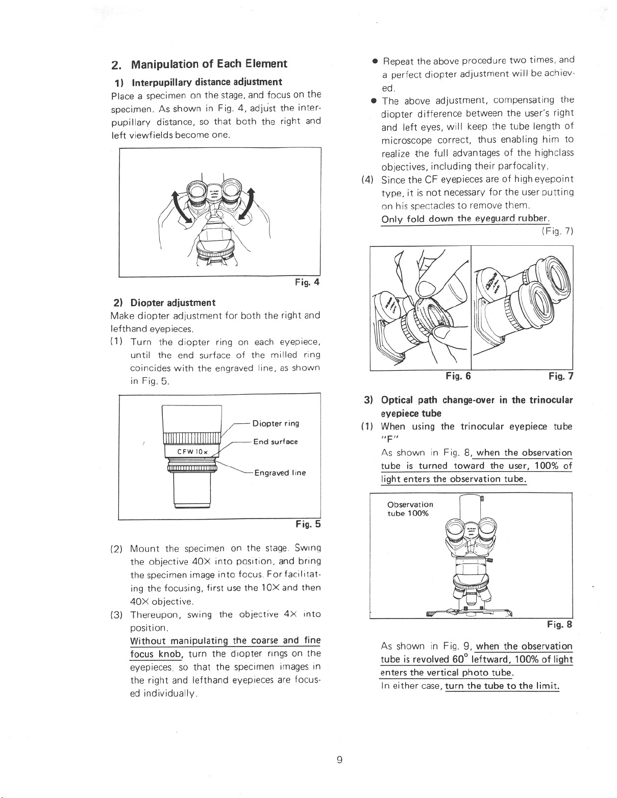
2. Manipulation of Each Element
1) Interpupillary distanceadjustment
Place a specimen on the stage,and focus on the
specimen. As shown in Fig. 4, adjust the inter-
pupillary distance, so that both the right and
left viewfields become one.
2) Diopter adjustment
Make diopter adjustment for both the right and
lefthand eyepieces.
(1) Turn the diopter ring on each eyepiece,
until the end surface of the milled ring
coincides with the engraved line, as shown
in Fig. 5.
• Repeat the above procedure two times, and
a perfect diopter adjustment will be achiev-
ed.
• The above adjustment, compensating the
diopter difference between the user's right
and left eyes, will keep the tube length of
microscope correct, thus enabling him to
realize the full advantages of the highclass
objectives, including their parfocality.
(4) Since the CF eyepieces are of high eyepoint
type, it is not necessary for the user putting
on his spectacles to remove them.
Only fold down the eyeguard rubber.
(Fig.7)
Fig. 6
Fig. 7
Diopter ring
End surface
Engraved line
Fig. 5
(2) Mount the specimen on the stage. Swmg
the objective 40X into position, and bring
the specimen image into focus. For facilitat·
ing the focusing, first use the
lOX and then
40X objective.
(3) Thereupon, swing the objective 4X mto
position.
Without manipulating the coarse and fine
focus knob, turn the diopter rings on the
eyepieces, so that the specimen images in
the right and lefthand eyepieces are focus-
ed individually
3) Optical path change-over in the trinocular
eyepiece tube
(1) When using the trinocular eyepiece tube
As shown in Fig. 8, when the observation
tube is turned toward the user, 100% of
light enters the observation tube.
Observation
tube 100%
Fig. 8
As shown in Fig. 9, when the observation
tube is revolved 60° leftward, 100% of light
enters the vertical photo tube.
In either case,turn the tube to the limit.
9
Page 10

Vertical photo
tube 100%
Fig. 9
(2) When using the trinocular eyepiece tube
"T" or the ultra wide eyepiece tube
"UW"
As shown in Fig. 10, with the change-over
knob pushed in, 100% of light enters the
observation tube.
Observation
tube
100"10
Optical path
change-over
knob
denser vertically so that a sharp image of
the field diaphragm is formed on the speci-
men surface.
(2) Bring the field diaphragm image to the
center of the field of view by means of the
condenser centering screws. (Fig. 12-W)
(3) Change over to the 40X objective, and
adjust the field diaphragm so that the
image of the diaphragm is about the same
as that of the field of view, as shown in Fig.
12-[Z]. If not centered, use the condenser
centering screws again.
Image of field
diaphragm
Eyepiece
viewfield stop
---
"",r Image of field
'\ diaphragm
Fig. 10
As shown in Fig. 11, with the change-over
knob drawn out, the proportion of light
entering the binocular observation tube
and vertical photo tube will be 14 : 86.
Observation tube:
vertical photo
tube = 14:86
Optical path
change-over
knob
Fig. 11
4) Centering the condenser lens
(1) Close the field diaphragm in the microscope
base to its smallest size by means of the
field diaphragm control ring. Rotate the
condenser focus knob to move the con-
Eyepiece
viewfield stop
Fig. 12
5) Use of condenser aperture diaphragm
The condenser aperture diaphragm is provided
for adjusting the numerical aperture (N.A.) of
the illuminating system of microscope. It is
important because it determines the resolution,
contrast and depth of focus.
In general, when it is stopped down to 70 ~
80% of the numerical aperture of the objective,
a good image of appropriate contrast will be
obtained. (Fig. 13)
Objective pupil
Aperture diaphragm
Size of the condenser aperture diaphragm
Fig. 13
10
Page 11

The graduation on the Abbe condenser indicates
the diameters in mm of the aperture diaphragm
opening of condenser..
After removing the eyepiece from the eyepiece
tube, adjust the size of the diaphragm, observ-
ing the image of the diaphragm which is visible
on the bright circle of exit pupil of objective
inside.
It is recommended to take note of the diameter
of the diaphragm opening for each objective
power, whereby the best image is obtained.
The Swing-out Achromat and Achromat/
aplanat condensers, however,
indicating the numerical apertures (N.A.l. and
not the diameters of diaphragm opening.
Manipulation of these condensers isthe same as
that of the Abbe condenser. Stopping down the
aperture diaphragm too far will deteriorate the
image quality of microscope due to diffraction
of light. Therefore, it is not recommended to
stop down the aperture to a size smaller than
60% of the N.A. of the objective in useexcept
when observing almost transparent specimen.
have a graduation
the stage4.7mm.
The range of coarse and fine motion is within
30mm; 2mm up and 28mm down from the
standard position.
Tightness of the coarse-fine focus knob having
been properly adjusted by the manufacturer,
it should never be readjusted in this model
microscope by turning the one knob while
holding the other.
J
6) Use of field diaphragm
The field diaphragm is used for determining the
illuminated area on the specimen surface in
relation to the field of view of the microscope.
Generally, it is stopped down to such an extent
that the circumference of the illuminated area
circumscribes or inscribes that of the eyepiece
field of view. If the former be larger than the
latter, extraneous light will enter the field of
view, causing flare in the image and lowering
the contrast. Therefore, especially in photo-
micrography, the proper adjustment of the field
diaphragm is very important. Generally, good
results will be achieved when the diaphragm is
stopped down to such an extent that the dia-
meter of illuminated area is slightly larger than
the diagonal of film format.
7) Focusing
The relation between the direction of rotation
of the focus knobs and that of vertical move-
ment of the stage is as indicated in Fig. 14.
One rotation of the fine focus knob moves the
stage O.2mm.
The graduation on this focus knob is divided
2J.Lm.
into
One rotation of the coarse focus knob moves
11
Page 12

IV. OPTICAL SYSTEM
The CF objectives and CF eyepieces adopted in
the Nikon Biological Microscope LABOPHOT
are designed on the basis of a new Nikon-
developed concept "Chromatic Aberration
Free" With the Nikon CF optical system the
chromatic difference of magnification in the
objective and eyepiece is individually corrected.
This is unlike conventional microscopes where
the corrections of such aberration has been, for
the most part, compensated for in the objectives
and eyepiece as a pair. As a result the Nikon
Microscope LABOPHOT has no orange colored
fringe in the eyepiece. In cooperation with the
other optimum aberration corrections such as
the Nikon Integrated Coating, a uniformly
sharp image, much superior in resolution,
contrast and color rendition is achieved over
100% of the effective, even, super-wide field of
view, for observation as well as color photo-
micrography.
.1. Objectives
Mechanical tube length of 160mm and parfocal
distance of 45mm (This is longer than the
33.6mm of earlier microscopes). In every case
use the CF objectives in combination with the
CF eyepieces.
1) Types of objective
(1) Achromat (CF)
In this type of objective, the correction of
chromatic aberrations is based on the lines
C (red) and F (blue). Importance being
given to the correction at the center of
viewfield, the objectives offer the finest
definition and highest contrast of image
at the center. Even the 40X and lOOX
objectives fulfill the "Chromatic Aberra-
tion Free" correction, wh ich has been
considered difficult so far until now for
such high magnifying powers. Furthermore,
image flatness has been attained to an
appreciable extent.
(2) Plan Achromat (CF Plan)
Same as the above type, the objectives ac-
complish the correction of chromatic
aberrations based on the lines C and F.
In addition, owing to sufficient correction
of all the image defects up to the periphery
of viewfield, the objectives provide an
unsurpassable high resolution and contrast
of image over a wider field.
Focusing at the center means simuItaneous
focusing at the marginal part of viewfield.
They are excellent for ultra-wide observa-
tion and photomicrography.
(3) Plan Apochromat (CF Plan Apo)
The use of fluorite and special, low color
dispersion optical glasses improves the
correction of chromatic aberrations over
the ent ire visible region up to the line g
(violet) along with the lines C and F.
These highest-grade objectives wi th their
large numerical apertures produce an ideal
image over a wide viewfield. With their
outstanding definition, superior color re-
producibility, and prominent image flat-
ness, they are especially suited for most
profound study of minute structures and
color photomicrography .
(4) Epi-fluorescence (CF UV-F)
Exclusively designed for episcopic, fluo-
rescence observat ion, th is type objectives
use non-fluorescent and non-solarisation
materials and a strictly chosen cementing
agent, to increase the transmission of UV
exciti ng light (u Itra-vi olet rays). Special
weight being attached to the correction at
the center of viewfield, and the numerical
apertures made extremely large, they
ensure bright and sharp fluorescence images
using every excitation method. As im-
mersion fluid, the objectives
of this type require the use of non-fluo-
rescent glycerine of high purity.
2) Useof the objective
(1) "Oil immersion objectives (Oil)
The objectives discriminated by the engrav-
ing "Oil" are to be immersed in oil between
the specimen and front of the objective.
When using oil immersion objectives of
numerical aperture 1.0 or higher, it is rec-
ommended, for making full use of its
efficiency, to use a highclass oil-immersion
condenser such as of Achromat/aplanat
type, applying oil between the glass slide
and condenser as well.
lOX ~ lOOX
12
Page 13

To see if air bubbles are present in the
immersion oil, which deteriorate the image
quality, pullout the eyepiece from the
eyepiece tube to examine the
objective exit
pupil inside the tube.
remove air bubbles, revolve the nose-
To
piece slightly to and fro several times,
apply additional oil, or replace the oil.
Be careful not to rotate the nosepiece too
far as to soil the ends of the other objec-
tives with oil.
To clean off the oil, passlens tissue or soft
cloth moistened with xylene lightly two or
three times
over the lens. It is essential at
this time to avoid touching the lens with
the part of tissue or cloth once used.
Any remnants of oil left on the lens dete-
riorate the image quality.
(2) Coverglass
With the objectives engraved "160/0.17",
use a coverglass of O.17mm in thickness
(No. 1%). For the objectives whose N.A is
0.75 or higher, a coverglass of other thick-
ness than 0.17mm will deteriorate the
image definition and contrast.
The indication 160/- on the objective
means that no matter whether a coverglass
is used or not, no decrease of image defini-
tion or of contrast wi II resuIt.
(3) Objectives with compensation ring
When a high power, dry objective of large
N.A is adopted in combination with a
coverglass of thickness other than 0.17mm,
which will cause sharp reduction of image
definition and contrast, it is necessary to
use an objective incorporating a compensa-
tion ring asbelow:
First, observe with the compensation ring
set to 0.17, and then rotating the ring,
focus the image with the fine focus knob,
until an image of the highest sharpness and
contrast is obtained.
(4) No-coverglass objectives (NCG)
Objectives with the indication NCG are
suited for observing specimens such as
smearswithout coverglass.
(5) Objectives with aperture diaphragm
The objective incorporating an iris dia-
phragm serves to cut off direct light in
darkfield microscopy. Stop down the
diaphragm nearly to its minimum opening.
2, Eyepieces
To take full advantage of the CF eyepieces, use
them in combination with the CF objectives.
The indication "CF" should
their usewith other type objectives.
1) CFD eyepieces(CFD)
Being of wide field and high eyepoint type, the
CFD eyepieces are only used for observation,
obtains prominent image flatness. Compared
with the CFW eyepieces, they accomplish the
good correction of chromatic aberrations at the
periphery of the viewfield in combination with
the low magnifying power of CF Plan
Apochromat objectives.
They are equipped with a diopter ring and a
rubber eyeguard. An eyepiece CFD
incorporating a photo mask, is also available,
which enables focusing and framing by the use
of the observation tube of the Trinocular
Eyepiece Tube "T".
2) CFW eyepieces(CFW)
Being of wide field and high eyepoint type, the
CFW eyepieces with diopter ring are only used
for observation. They are equipped with a
rubber eyeguard.
An eyepiece called CFW lOX M, incorporating
a photo mask is also available, which enables
focusing and framing by the useof the observa-
tion tube of the Trinocular Eyepiece Tube "T".
3) CFUW eyepiece (CFUW)
Featuring extra-wide field of view and high
eyepoint, this eyepiece with diopter ring is
designed exclusively for observation. It enables
observation over a field of view twice as large as
that of the ordinary type eyepieces in combina-
tion with the ultra-wide tube.
An eyepiece called CF UW lOXM, incorporating
a photo mask, is also available, which enables
focusing and framing by the useof the observa-
tion tube of the Ultra Wide Eyepiece Tube
"UW".
4) CF PL Projection lenses(CF PL)
Exclusively designed for photomicrography. Do
not usethem for observation.
Every eyepiece is liable to gather dirt and dust,
which not only appear as shadows but also
impair image quality and contrast.
Keep the eyepieces clean at all times.
serve to prevent
lOXM,
13
Page 14

3. Condensers
1) Abbe condenser
NA = 1.25. This is used with 4X - 100X ob-
jectives. The graduation of this condenser
indicates the diameters in mm of the aperture
diaphragm opening.
2) Swing-out Achromat condenser
= 0.9. Dry system.
N.A.
It is used in combination with objectives from
2X to 100X, and provided with a swing-out top
lens which is to be swung out when using the
2X or 4X objective. Its adjustable aperture scale
is graduated in N.A. ratings.
3) Achromat/aplanat condenser
NA
= 1.35. Oil system.
The spherical, coma and chrom<ltic aberrations
being ideally corrected, this large aperture
condenser is used with 20 X - 100 X objectives.
The standard thickness of glass slide should be
1.2mm.
Apply oil between the condenser and glassslide.
It is recommended that this condenser be
employed especially in combination with the
Plan Apochromat objectives. When using the
lOOX objective for observation in combination
with the CFW lOX eyepiece, it is possible to
close the field diaphragm down to 45% of the
viewfield.
4) Darkfield condenser(Oil)
= 1.43 - 1.20. Oil system. Used in dark-
N.A.
field microscopy. Apply oil between the
condenser and glass slide. (It is recommended
to usea thinner glassslide.)
This condenser is used in combination with the
objectives lOX - lOOX with aperture dia-
phragm (N.A.: up to 1.11.
5) Darkfield condenser(Dry)
= 0.95 - 0.8. Dry system. Used in dark-
N.A.
field microscopy. Magnifying powers of usable
objectives are lOX - 40X (N.A.: up to 0.7).
4. Illumination System (Fig. 15)
The optical system for illumination in the
LABOPHOT microscope is constructed to fulfill
the Koehler illumination requirements perfect-
ly, and offers a bright, uniform field without
any change-over manipulation.
As a standard light source, use the Halogen
lamp 6V 20W (PHI LIPS 7388).
OPTICAL PATH
Collector
lens
Halogen
lamp
Objective
Filter
Field lens
Fig. 15
14
Page 15

(J1
5. Combinations of Objectives and Eyepieces
-
-
Depth 01 locus:
Glycerin
-
M
8x
16 x
32 X
32'x
M
M
.um
16x
With compen-
sal,on flng
80x
tJrnm
distance
Dowerlhlcknessndication
M¢mm
o 17
-
0.17
mm
2X(NAl' 7XN.A.xM
Real
Real
10
Real
dls1ance
nilicahon
locus
W.O.mmImm"m
¢ mm
¢mm
"m
o. I7
-
-
-
-
focus
viewtield
mfication
Depth 01
vlewfleld
WOfKlngFocusing
RealDepth of
Depth 01
v;ew'ield
nification
focus
viewfieldlocus
-
40 x
80x
"m
"m
Resolving
Total mag
Total mag
Total mag
non800x
non
lOx
n:Relractlve index of
DePTh of
Cove/glass
60x
1 8
0.45
0.3
non320x
50x
480x
non800X
u.
Total mag
4.5
1 7
800x
018
003
18
14
4.5
7 1
1 1
320x
11
1 7
1
0.45
09
1.8
1.4
160x
100x
0.9
4 1
045
2.8032
030.7
0306900x0.2305
04406
17
0.45
1 3
0343.2
400x
12
0.3611750x
31.0
5.3
4.1100x2 753
10013 90.28
320 x
1.1
1.0
0.8
06610
0.9012 9031
0.3
72
16.61.1
1.811.5
065
04
0.4
800x
05
0.450.8
07600x
06400x06607
0.085367 934
1.3
900x
26032
0.5
018
1500x
0.4
041500x
1000x
90155
9.0
30x
102
13.3
0164.733611 701732 x4 539
3360x3526
6.633
0403314.2069017
1 8
057 9042017160x0920
4 20.29
0180.4
0.18041500xo 14031000x
04
01804
04
0.3
02704
I 8108 79 2
18900
782
623
00')') 870. I5.5
90
25330x7.020520x13.3253
0113.8
28
4.572
6360x355140x6663
16 7
11 5
40x
0.45
0.4
09
1.3
1 2
09
017
47lOOx1.84.0
1.4
01780x1.869lOOx
1.44.4
160x
1 7
300x07
034
23200x
2.0
01
017
08
0.45
1 7
04
0180.4
03
02
0.1
017
0180.5
1.6
wavelength I
022
0.4
0.4
017
12
10
0.661.2
1.8
200x1 31.8
10.1
8.2
2 710 I
84069
160x0.9
2 9
09400x0.45
035o
3.5300x0.72.9200x1.3
048
0.42
320x0451.3
1.2
10400x0.661 2
035
600x
600x
0.45
1.6
035
032017
036
500x
0.2809500x0531.1
20
28
150x1.4
017
045
400x
600x035
400x
0.7600x
07900X
0.440.7
40X456360x
56
lOOX1.810.1150X1.48.2
4.4
1 25
018
1500X0.14
022
0.18
0.35
0.45
0.30.7
0.307
0.2306600x0440.7
0.85
0.18
1000x
05
014
1000x0.27
021.80.220.17800X0.18051000x018
0.1404
0.270.4
132
7 .0
20x
132
40x
40x
80x
6 2
065
02o 17
027
1000x
1500x0.14
1000x
lOX
289
9.0
4011
40x
0.2')
1.8
0.65
4.2042
228.80.69
4.0
0.93.5300x072 9
045
400X0.45
600x0.3510
134005
0.55
80x1.8
150x
30
0.28162
1.85.8
7.80.37017
0.9
200x091.4
20x
8 9
0.17160x09
0.9
300x0.71 5
1.3
320x045
400X
0.6600x03505lOa x1.3
0.210.17
1000x
1500X0.14
0.9
031
800x0.18051000x
1500x0.140.41000x0270.5
0.31
1.8
017800Xo 18051000x018
1500x0.14
Wdh compen-
600x0.35
400x
300x0.71.4
150x1.4
100x
04
017
40
8.80690.17
0.940200x0.93.5300x0.7
0.374.20320.17320x
08600x
3 5
065
017
600x0.35
085
600X
0.85
0.1
0.2306600x
45
3.551025
053
0420.17
0.14
017
400x
600x
0.43
05
20X
200x
1000x
20x
lOOX
200X
.14.3
0.55
150X
0.75066
0.802
40x
4.50.21
013
800X018
1 25014
200x
04223
085
045
400x
400X
05
lOa x
055
05
480 x
0.,9:..\7,,,480x
320 X
0
::>
320x
160x
nxA
(Resolving power at eye=2'
Resolving power: __ A__
CF Objectives (160/45)
-
NCG
1
1 3')o 17
7
0.45
Magnification
0,1
15 x
0.90.26
1.25
20 x
I 3')
60x
40x
20x
100x
+ n
100x
20x
aperTure
40x
2XNA
Field number= 18
CFW15X
Field number= 26.5
CFW lOX
CFUW lOX
40 x095 400x
0,1
FieId number.-14
60x
01
1.8
1011- 0 23)
1000x
10- 2.0)
10- 2.01
Ultra-Wide vlewfleld
CFW8x
( A= O.5511mSianda'd
Ordinary viewfield
CF Eyepieces
Table 2
object side)
Page 16
v .PHOTOMICROGRAPHY
(The Biological Microscope LABOPHOT IS
designed mainly for observation.)
1. Combination of CF Objectives and
CF
PL Projection lens
The combined use of the CF objectives and CF
PL Projection lens is essential.
For the same total magnification, select a
combination of the highest possible objective
power and lowest possible projection lens
power to achieve the utmost image definition
and contrast.
2. Checking the Illumination
Uneveness in the illumination will show up
more conspicuously in photomicrography than
in observation. Consequently, before taking a
photograph, recheck the correct adjustment of
the condenser.
3. Selection of Voltage and Filter
1) When using a daylight type color fil m
Set the brightness control dial to 5.5 and use
the NCB 10 fi Iter
Adjustment of the image brightness should be
made by meansof the NO filters.
2) When using a monochrome film
Remove the NCB 10 fi Iter. Contrast fi Iters such
as X-1 green are usable.
*-' The NCB 10 filter is most suitable for a
standard film. Depending upon the make
of the film different color renditions may
result. It is recommended that in addition
to the NCB 10 filter a color compensation
filter (CC filter), available from the film
manufacturer, be used.
*-'
"UW" tube
"F" tube
or
tube
finder
eyepiece
"T"
Use
Use
Failure" of film may result. So, when taking
picture of such specimens, it is recommended
to use the Nikon Biological microscope OPTI-
PHOTo
5. Manipulation of Field and Aperture
Diaphragms
In photomicrography, the adjustment of the
field diaphragm is important for the purpose of
limiting extraneous light which causes flare in
the microscope image. Stop down the dia-
phragm so as to get an illuminated area slightly
larger than that of the picture field. By adjust-
ing the aperture diaphragm, a change of depth
of focus, contrast and resolution of image is
attainable. Select a size suited to the purpose.
Generally speaking, the aperture diaphragm, is
properly stopped down to 70 ~ 80% of the
aperture of the objective being used.
6. With Regardto Condensers
For photomicrography, it is generally rec-
ommended to use the Swing-out Achromat
condenser. When using 2X objective, however,
preferab Iy remove the condenser.
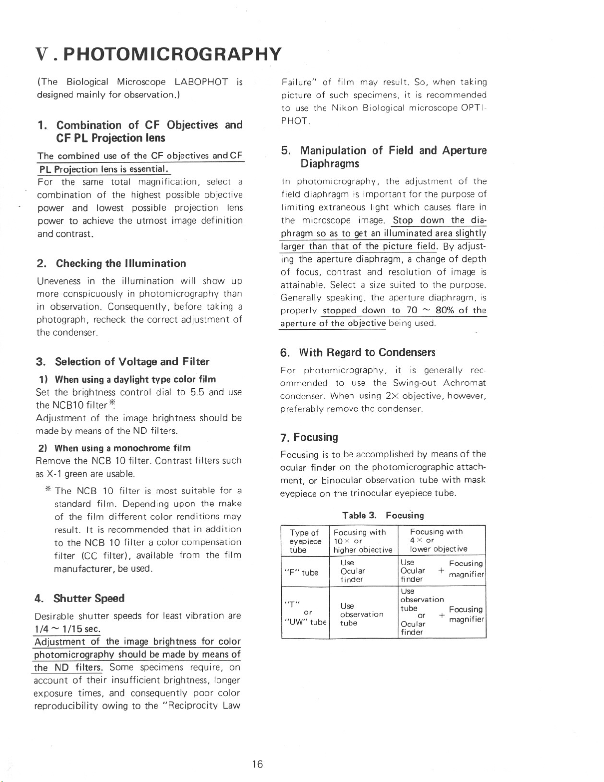
7. Focusing
Focusing is to be accomplished by means of the
ocular finder on the photomicrographic attach-
ment, or binocular observation tube with mask
eyepiece on the trinocular eyepiece tube.
Table 3. Focusing
observation
4 x or
Ocular
Use
Ocular
10x or
Type of
or
finder
Use
+ magnifier
fi nder
lower objective
Focusing with
tubeOcular
observation
higher objective
Focusing with
Focusing
tube
+ magnifier
Focusing
4. Shutter Speed
Desirable shutter speeds for least vibration are
1/4~ 1/15sec.
Adjustment of the image brightness for color
photomicrography should be made by means of
the NO filters. Some specimens require, on
account of their insufficient brightness, longer
exposure times, and consequently poor color
reproducibility owing to the "Reciprocity Law
16
Page 17
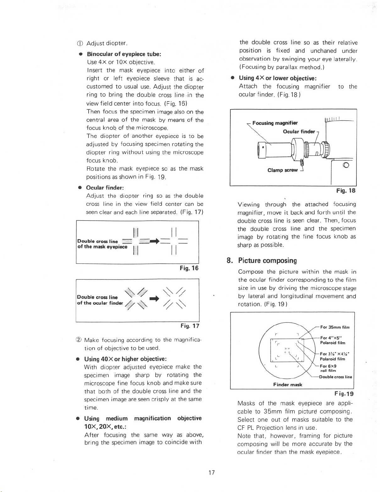
CD Adjust diopter.
• Binocular of eyepiece tube:
Use4X or lOx objective.
Insert the mask eyepiece into either of
right or left eyepiece sleeve that is ac-
customed to usual use. Adjust the dioPter
ring to bring the double cross line in the
view field center into focus. (Fig. 16)
Then focus the specimen image also on the
central area of the mask by means of the
focus knoq of the microscope.
The diopter of another eyepiece is to be
adjusted by focusing specimen rotating the
diopter ring without using the microscope
focus knob.
Rotate the mask eyepiece so as the mask
positions asshown in Fig. 19.
• Ocular finder:
Adjust the diopter ring so as the double
cross line in the
view field center can be
seenclear and each line separated. (Fig. 17)
Double cross line ::::::mE''':;''' __
of the mask eyepiece II II
Double cross line «; <» ••• ~ ~
of the ocu lar finder Af;7 ~ ~ ~
111 __ II
Fig. 16
the double cross line so as their relative
position is fixed and unchaned under
observation by swinging your eye laterally.
(Focusing by parallax method.)
• Using 4X or lower objective:
Attach the focusing magnifier to the
ocular finder. (Fig. 18)
Focusing magnifier
Ocular finder
\lilill
Viewing through the attached focusing
magnifier, move it back and forth until the
double cross line is seen clear. Then, focus
the double cross line and the specimen
image by rotating the fine focus knob as
sharp as possible.
8. Picture composing
Compose the picture within the mask in
the ocular finder corresponding to the film
size in use by driving the microscope stage
by lateral and longitudinal
rotation. (Fig. 19)
movement and
o
Fig. 18
Fig. 17
(2) Make focusing according to the magnifica-
tion of objective to be used.
• Using 40X or higher objective:
With diopter adjusted eyepiece make the
specimen image sharp by rotating the
microscope fine focus knob and make sure
that both of the double cross line and the
specimen image are seen crisply at the same
time.
• Using medium magnification objective
10X, 20X, etc.:
After focusing the same way as
above,
bring the specimen image to coincide with
17
For 3Smmfilm
For 4"XS"
Polaroid film
ForJ~'X4~'
Polaroid film
For6X9
roll film
Double crossline
Finder mask
Fig.19
Masks of the mask eyepiece are appli-
cable to 35mm film picturE! composing .
Select one out of masks suitable to the
CF PL Projection lens in use.
Note that, however, framing for picture
composing will be more accurate by the
ocular finder than the mask eyepiece.
Page 18
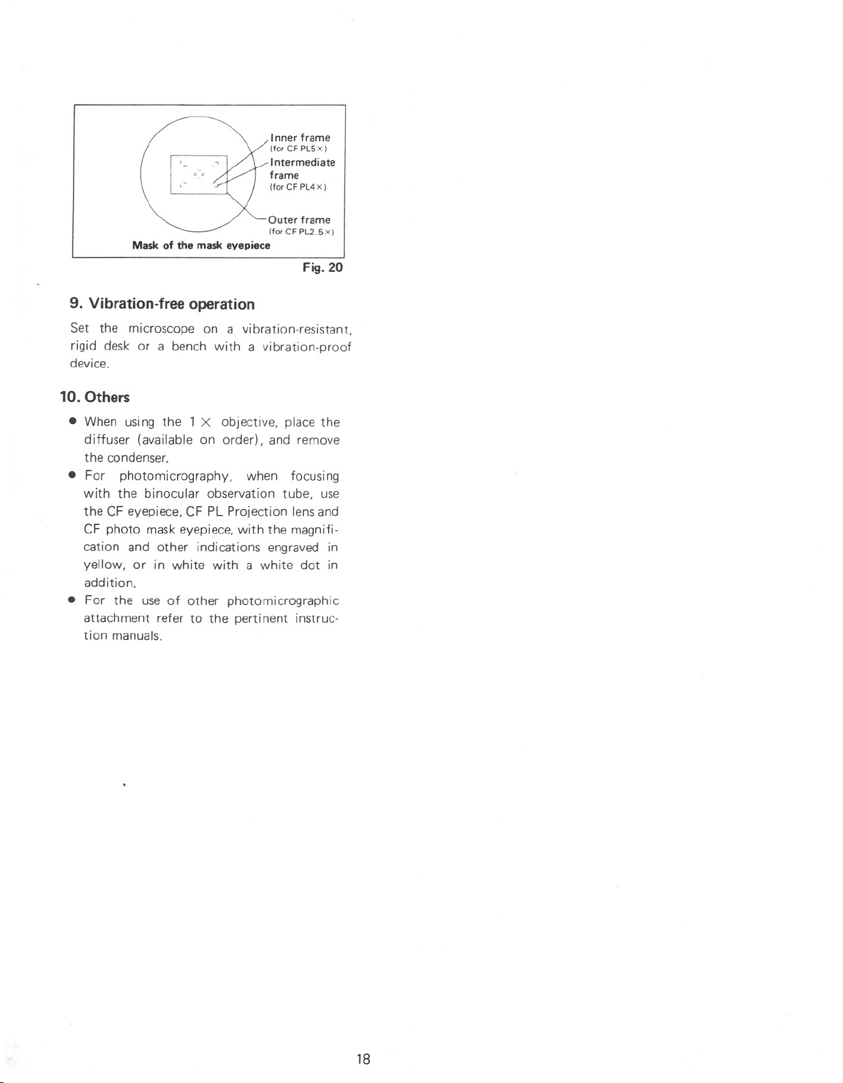
Inner frame
(for CF PL5 X)
Intermediate
frame
(forCF PL4X)
Outer frame
(forCF PL2.5X)
Mask of the mask eve piece
Fig. 20
9. Vibration-free operation
Set the microscope on a vibration-resistant.
rigid desk or a bench with a vibration-proof
device.
10. Others
• When using the 1 X objective. place the
diffuser (available on order), and remove
the condenser.
• For photomicrography, when focusing
with the binocular observation tube, use
the CF eyepiece, CF PL Projection lens and
CF photo mask eyepiece. with the magnifi-
cation and other indications engraved in
yellow, or in white with a white dot in
addition.
• For the use of other photomicrographic
attachment refer to the perti nent instruc-
tion manuals.
18
Page 19

VI. USE OF THE ACCESSORIES
1. Ultra Wide Field Trinocular Eyepiece
Tube "UW"
1) Objectives
CF Plan Achromat 2X'" lOOX, CF Plan Apo-
chromat 2X'" lOOX, CF Plan Achromat for
phase contrast 1OX'" lOOX, CF Plan Achromat
for metallurgical 5X '" lOOX, CF Plan Apo-
chromat for metallurgical 50X or CF SO Plan
Achromat for bright and darkfield 5X'" 1OOX
are used.
2) Condenser
Refer to the Table 1 (P.8).
3) Assembly and microscopy
Assembly and microscopy being almost the
same as that of the regular microscopy (P. 6
and P. 8). only the differences will be described
below.
(1) Using the centering telescope
For attaching the centering telescope on
top of the eyepiece sleeve, it is necessary to
use the adapter (Fig. 21), because the tele-
scope which has been originally designed
for centering the annular diaphragm in
phase contrast microscopy, has a fitti ng
diameter different from that of the CFUW
eyepiece.
2. Polarizing Filter Set "PT"
1) Nomenclature (Fig. 22)
Analyzer
Polarizer
2) Assembly
(1) Attaching the analyzer
After removing the eyepiece tube, insert
the analyzer into the optical path hole in
the microscope arm. (Fig. 23)
The white index dot is to be brought into
coincidence with the Y-axis (of X-V co-
ordinates), viewing the arm from above.
"
White ~y
indexdot~AnaIYZ~r
•
Fig. 22
Fig. 21
Fig. 23
(2) Condenser
Usethe Swing-out condenser.
(3) Attaching the polarizer
As shown in Fig. 24, fit the polarizer to the
internal diameter at the bottom of the
condenser.
t
S--POlarizer
Fig. 24
19
Page 20
(4) Objective
Usethe ordinary CF objectives.
3) Microscopy
(1) Turn ON the power switch. Set the bright-
nesscontrol dial to 4.
(2) Remove the dust cap and place the daylight
filter.
(3) Place the specimen on the stage and focus
on specimen with 10Xobjective.
(4) Adjust the interpupi Ilary distance and
diopter. (Refer to P. 9)
(5) Swing in the top lens of the swing-out
condenser in the optical path. (If using 4X
objective swing out the top lens.)
(6) Center the condenser. (Refer to P. 10)
(7) Rotate the polarizer until the darkest field
view is obtained.
of
(8) Set the brightness control dial to 5 - 6.
(9) Change
over the objective to be used and
sharpen the focus on the specimen.
(10) Adjust the apertu re diaphragm and field
diaphragm. (Refer to P. 10 and 11)
(NOTE)
The following accessories can not be used in
combination with LABOPHOT (Y-R stand)
Microscope.
eTeaching Head and Multi-teaching Head
(Only when they are combined with Ultra
Wide Eyepiece Tube "UW")
eEpi-iliuminator "M"
20
Page 21

VII. TROUBLE SHOOTING TABLE
Although nowhere the user can find any disorder or derangement in the instrument, if he
encountes some difficulty or dissatisfaction, recheck the use, referring to the table below:
1. Optical
field
resolution or
(No appearance
Image quality
)Actions
• Dirt or dust on the lens
• No coverglass attached to slide or
• Condenser not centered ) Centering by using field dia-
• Too thick or thin coverglass
• Condenser aperture too much closed
Failures
• Dirt or dust on the entrance lens
(Refer to P. 10)
(Refer to P 10)
• Dirt or dust on the lens
• No immersion oil used on immersion---+ Use immersion oil
• Objective aperture (which provided)
field diaphragm image
• Dirt or dust on the slide
• Improper use of condenser
system objective
too much opened
• Revolving nosepiece not in click-
• Revolving nosepiece not in c1ick-
• Too low position of condenser
• Optical path in trinocular tube not
Causes
centered in optical path)
(Condenser, objective, eyepiece, field lens)
NCG objective used with coverglass
stop position (Objective not
stop position
fu Ily changed-over
(Refer to P. 9)
, Correct use (Refer to P. 10)
) Revolve it to click-stop position
) Remove bubbles
) Changing-over to the limit
) Cleaning
) Cleaning
) Use Nikon immersion oil
) Revolve it to click-stop position
' Cleaning
) Correct positioning
(Refer to P. 12)
) Correct use (Refer to P. 13)
) Open properly (Refer to P. 10)
) Use specified thickness (0.17mm)
) Cleaning
) Open it properly
, Cleaning
) Bring it up to coincidence with
) Cleaning
) Adjustment (Refer to P. 13)
) Open properly
ph ragm (Refer to P. 10)
coverglass (Refer to P. 13)
21
Page 22

Failures
• Condenser not correctly centered
Actions
• Specimen rises from stagesurface
• Revolving nosepiece not in c1ick-
• Daylight fi Iter not used
Causes
stop position
2. Manipulation
.
• Place it stable
, Revolve it to click-stop position
(Refer to P.9)
• Use daylight filter
• Correct centering (Refer to P.l0)
,Changing-over to the limit
Failures
slide
slide
smooth by
(when changed-over)
moving the
Movement of
No fusion of
High power ob-
Travel of stage
Fatigue of
Actions
Causes
.
holder
• Incorrect diopter adjustment
• Upside down of slide
• Upside down of slide
• Too thick coverglass ' Use specified thickness (O.17mm)
• Eyepiece diopter not adjusted' Diopter adjustment
• Slide holder not tightly fixed
• Eyepiece diopter not adjusted• Diopter adjustment
• Improper attaching of slide
• Interpupillary distance not
adjusted
• Too thick coverglass
(Especially when changing-over
• Inadequate brightness of illumination~ Change power voltage
' Turn over the slide
• Turn over the slide
(Refer to P 9)
• Use specified thickness (O.17mm)
) Fix it tightly
) Adjustment (Refer to P. 9)
) Correct adjustment(Refer to P.9)
) Shift the attaching position
(Refer to P 9)
coverglass (Refer to P. 13)
coverglass (Refer to P. 13)
22
Page 23

3. Electrical
illumination
Failures
bulb (PH ILIPS 7388)
(Refer to P. 10)
• House current voltage fluctuates
• Lamp bulb insufficiently inserted
• Too low voltage
Actions
• Fuse blown
• Lamp bulb going to be blown
• Lamp bulb not inserted to the limit
• No lamp bulb attached • Attaching
• Lamp bulb blown ) Replacement
• Condenser not centered
• Not specified fuse used ) Use 1A (250V) or O.5A (250V)
• Fuse holder not firmly fastened
• Irregular change of house current
• Input voltage not adjusted to
• Not specified lamp bulb used
• Condenser aperture too much c1osed---. Open it properly (Refer to P. 10)
• Too low position of condenser
• No electricity obtained
• Too high voltage of house current
Causes
house current voltage (for Europeanthe microscope bottom
districts only)
•
• Secure connection
• Positive connection
• Usetransformer or the like
• Connect the cord to socket
• Use stabilizer
(for adequate voltage)
) Use transformer for adjustment
) Centering (Refer to P. 10)
• Replacement
) Turn the change-over switch on
I Use6V 20W specified lamp bulb:
• Correct positioning
• Replacement
• Use 6V 20W specified Halogen
• Cleaning
• Raise the voltage
• Firm fastening
(Halogen bulb: PHILIPS 7388)
picture
4. Photom icrography
Failures
crosshair.
addition.
separation appears between the image and double
• At lower magnifications use focusing telescope in
.· Actions
Causes
• Improper focusing----. • Viewing into the finder and turning diopter ring,
laterally, rotate fine focus knob, until no parallax
bring double crosshair into focus. Moving the eye
23
Page 24

)
Failures
• When contrast is to be increased for a part stained
more conspicuously
in observation)
contrast.
istics will be unavoidable.
white film).
black·and·white film).Note. however. for color film. that lowering of
in photography than
(Refer to P. 16)
chromatic interference filter (e.g. peak wavelength= 546nm. half-value range = 30 nm) will increase
color temperature and change of spectral character-
with a particular color. use a filter whose color iscomplementary to the stain color (for black-and-
• Using dry objectives---+. Use no·coverglass type objective.
on the specimen.
condenser lens. field lens. etc.
field diaphragm
for smear preparations
of coverglass
Actions
centered
• Out of focus
• Grease. dust or dirt----+. Clean the front of objective thoroughly. top surface
• Condenser not
• Aperture diaphragm---+. Generally. good resu Its wi II be achieved with
(No.1 %)
Causes
on optical surfaces
• Use objective With coverglass thickness compensa-
(This shows up
opened too large
of projection lens. specimen. photographic lens.
contrast microscopy. use of a green fi Iter or mono-
(Especially with high
• Select a place free from vibrations. such as caused
). Centering (Refer to P. 10)
tion ring.
aperture stopped down to 70 - 80% of N.A. of the
• If other objectives are to be used. place a coverglass
) • For preventing external vibration. use vibration-
proof table or rigid desk.
power objective and
by traffic. passers-by or motors etc.
larger than the diagonal of picture frame.
). In metallurgical. interference. polarizing or phase
objective being used. (Refer to P. 10)
(for color film. to 1/4 -1/15 sec.)• Lower the voltage. and elongate exposure time (for
24
Page 25

obtained
make or emulsion NO.
film development
source voltage
flare
resolving
graph
fi nder
Actions
)
filter
• Film of another
• Extraneous light~. Darken the surroundings or place the cap on the
Failures Causes
• In color photography, depending upon the speci-
• Incorrect exposure---->. By inadequate exposure time, color rendition willtime
of field is reduced.
• Specimens should be stained a rather dark color, if
• Even though of same make, according to emulsionnumber, different color rendition will be obtained.
• Stray Iight entering
• In black-and-white photography, for low contrast
is more suited (such as minicopy film).
cation
Then, with the help of exposure time indicator,adjust exposure time according to characteristics offilm by means of NO filters, or compensate forsuch fai Iure by means of CC fi Iters.(Refer to Kodak Data)
men, red-blue separation staining (Mallory or Azanmethods etc.) is preferable to red-violet combina-tion staining (H-E staining).
specimens a film of finer grain and higher contrast
• For general specimens a film of wider latitude and
upon the type, make, etc.
finer grain is preferable.
possible.
entering the ocularocular finder.
• Low contrasT in
• Inadequate useof-----. Select best filter combination.
• Insufficient N.A.~. Usea large N.A. objective.
-----+. Take care not to expose microscope and specimen
contrast. darkfield, or differential interference
resolving power.
of objective
• • Take picture in every caseat the specified voltage.
). To increase contrast optically, select phase
not be true on account of "reciprocity law failure"
• For the same magnification, increase power of
•• Note that, when using a daylight film, remarkably
different spectral sensitivities will result depending
specimen
mended to contact the development laboratory.
) • Especially, for making color prints, it is recom-
to direct sunlight and other intense lights.
higher resolution and sharpness, even though depth
methods.
objective rather than that of eyepiece to attain
(Refer to P. 16)
25
Page 26

Power source
Halogen lamp
220/240V
ELECTRIC SPECIFICATIONS
6V 20W
100V
120V
50/60 Hz
0.5A (250V)
220/240V
(PH ILIPS 7388)
100V}
1A (250V)
120V
Nikon reserves the right to make such altera-
tions in design as may be considered necessary
in the light of experience. For this reason.
particulars and illustrations in this handbook may
not conform in every detail to models in current
production.
27
Page 27

NIKON CORPORATION
FUJI BUILDING 2-3. MARUNOUCHI 3-CHOME,CHIYODA-KU, TOKYO 100,JAPAN
PHONE: 03-214-5311 TELEX: J22601 NIKON, FAX: 03-214-1780
Printed in Japan
6(89.2.B)H· E-6
 Loading...