

Nikon ED 17-55mm f/2.8G IF Repair Manual
JAA78851-R.3617.A
INC
作成承認印
AF-S DX Zoom-Nikkor
ED 17-55mm f/2.8G IF
配布許可印
JAA78851
REPAIR MANUAL
NIKON CORPORATION
Tokyo, Japan
Recycled paper
Printed in Japan March 2004
Copyright c 2004 by Nikon Corporation.
All Rights Reserved.

SPECIFICATIONS
INC
This lens can be used for Nikon digital SLR camera only.
JAA78851-R.3617.A
Type of lens
Focal length
Maximum aperture
Lens construction
Picture angle
Focal length scale
Distance information
Zoom control
Focusing
Shooting distance scale
Closest focus distance
Diaphragm
Aperture range
Exposure measurement
Attachment size
Dimensions
Weight
G-type AF Zoom- Nikkor lens having built-in CPU and Nikon F bayonet mount
17mm - 55mm (22.5 - 82.5 mm in 35 mm format)
f/2.8
14 elements in 10 groups (3 aspherical lens and 3 ED lens elements)
79° - 28° 50' (with Nikon Digital Camera D1/D1H/D1X/D100)
17,20,24,28,35,45,55mm
Output to camera body
Manually via separate zoom ring
Nikon Internal Focusing (IF) system (utilizing an internal Silent Wave Motor);
manually via separate focus ring
Graduated in meters and feet from 0.36m (1.25ft.) to innity (∞)
0.36m (1.2ft.) at all zoom settings
Fully automatic
f/2.8-f/22 at all zoom settings
Via full-aperture method with cameras having CPU interface system
77mm (P=0.75mm)
Approx. 85.5mm dia. ×110.5mm extension from the camera's lens mount ange
Approx.755g
- M1・AF-S DX17-55/2.8G -

JAA78851-R.3617.A
INC
※ Before Disassembly / (Re)assembly / Adjustment
If the 1st lens group and 4th lens group of this lens are removed, lens alignment
becomes necessary after assmbling.
Therefore, at service agencies where the lens alignment cannot be performed,
remove neither the 1st lens group nor 4th lens group.
- L1・AF-S DX17-55/2.8G -
DISASSEMBLY
INC
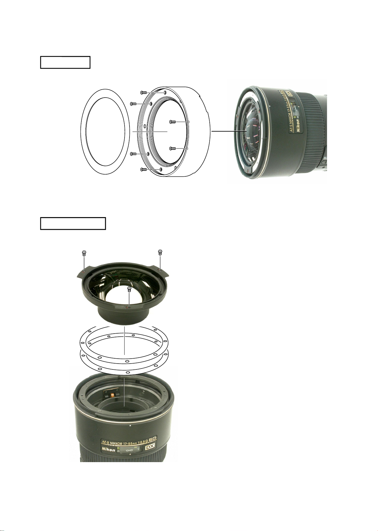
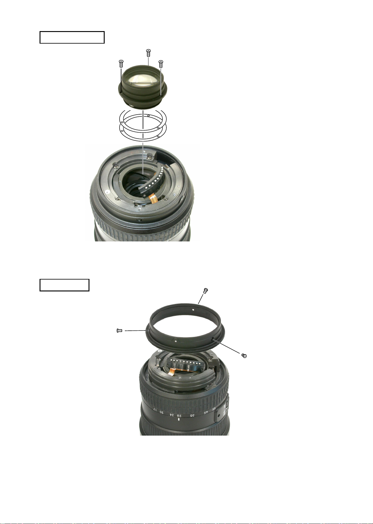
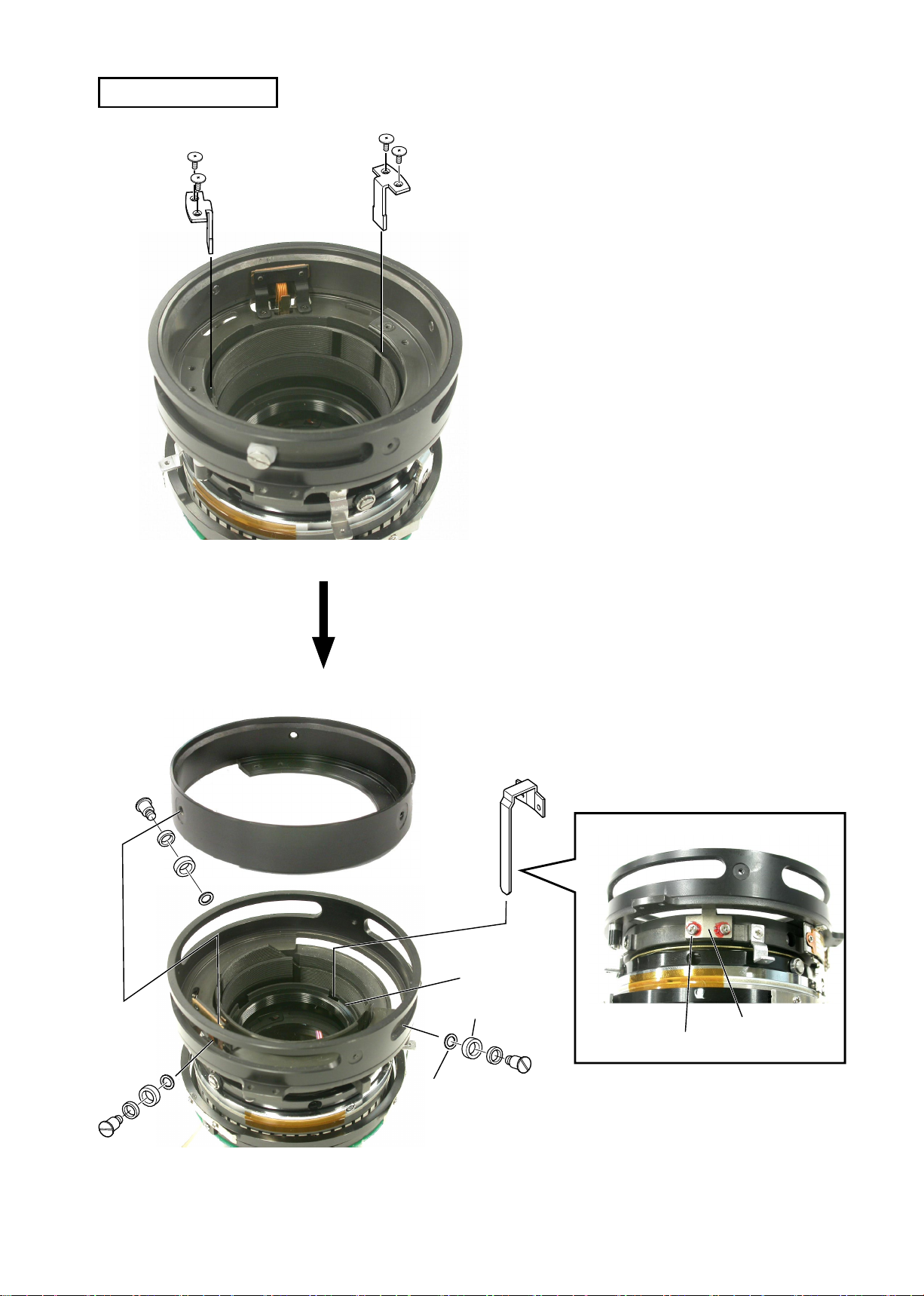
FILTER RING
JAA78851-R.3617.A
1ST LENS GROUP
#137
#50×6
Filter ring
#49×3
1st lens group
Note: If the 1st lens group is removed,
lens alignment of the 1st lens
group becomes necessary.
Therefore, at service facilities
where the point tester is not
prepared, do NOT disassemble.
#77
- L2・AF-S DX17-55/2.8G -
JAA78851-R.3617.A
INC
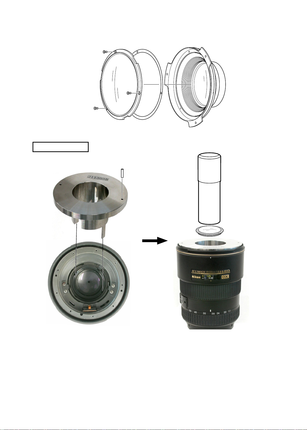
2ND LENS GROUP
#63×3
J11303B
B8 B11
#38
J11303C
J11303A
2nd lens group
Fig.1
Set the focus ring to the close-end, and the zoom ring to slightly 35-mm side from 28 mm.
・
Assemble J11303B into the cam ring to seat in notches of the cam ring, then insert the pin
・
(J11303C) into the hole of J11303B. (ref. Fig.1
Remove the 2nd lens group with the wrench for 2G AF-S 17-35DX (J11303A). (ref. Fig.2)
・
)
Fig.2
- L3・AF-S DX17-55/2.8G -
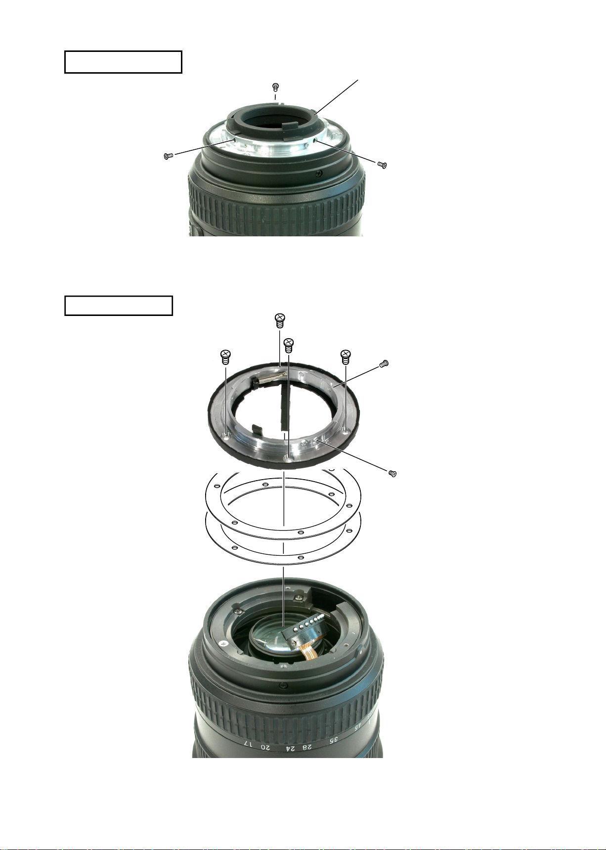
REAR COVER RING
INC
BAYONET MOUNT
JAA78851-R.3617.A
Rear cover ring
#182×3
#172×4
#78
#180×2
- L4・AF-S DX17-55/2.8G -
4TH LENS GROUP
INC
#71×3
4th lens group
#47
JAA78851-R.3617.A
Note: If the 4th lens group is removed,
the lens alignment becomes
necessary. Therefore, at service
facilities where the lens alignment
equipment is not prepared, do not
disassemble.
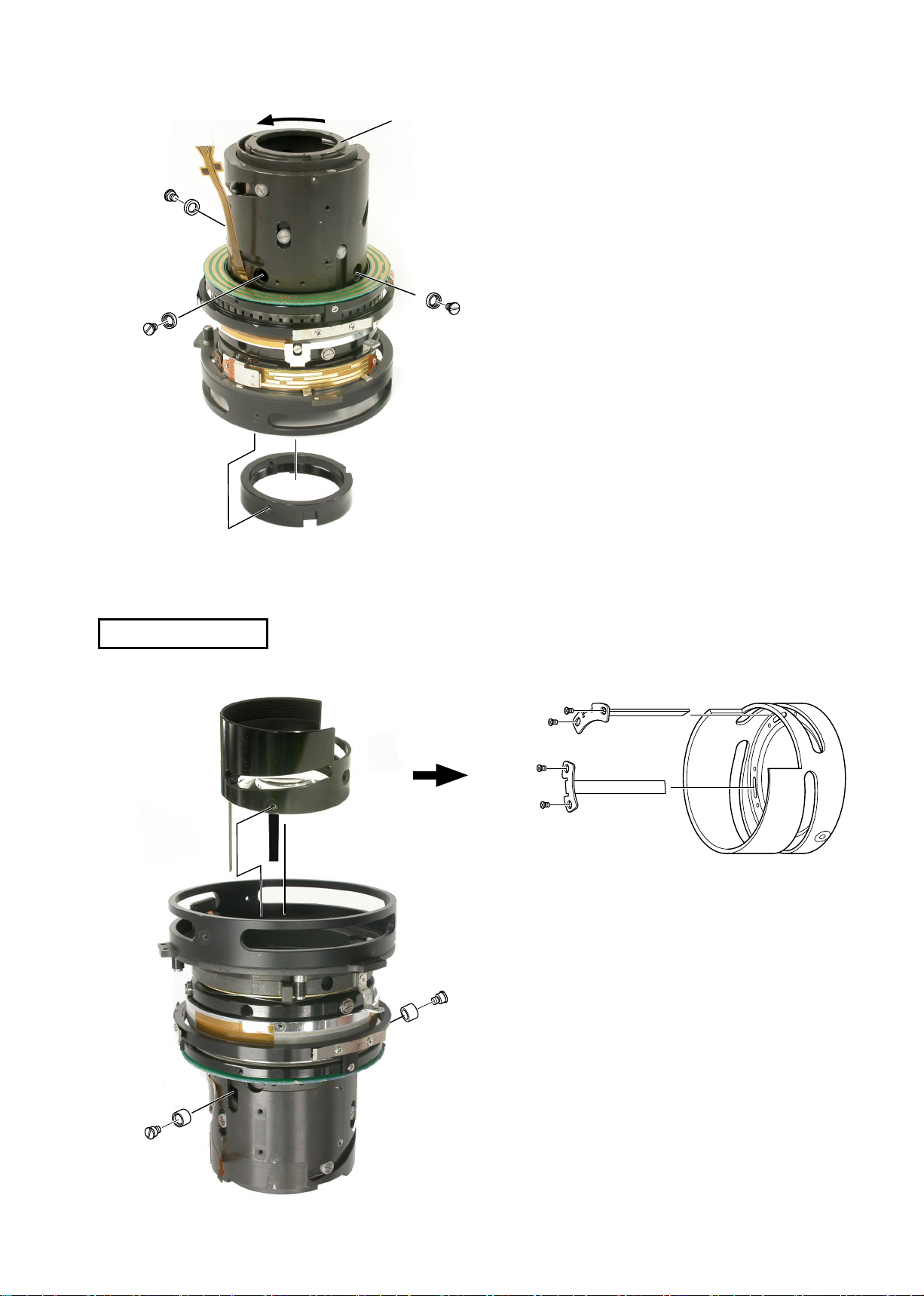
INDEX RING
Index ring
#128×3
- L5・AF-S DX17-55/2.8G -
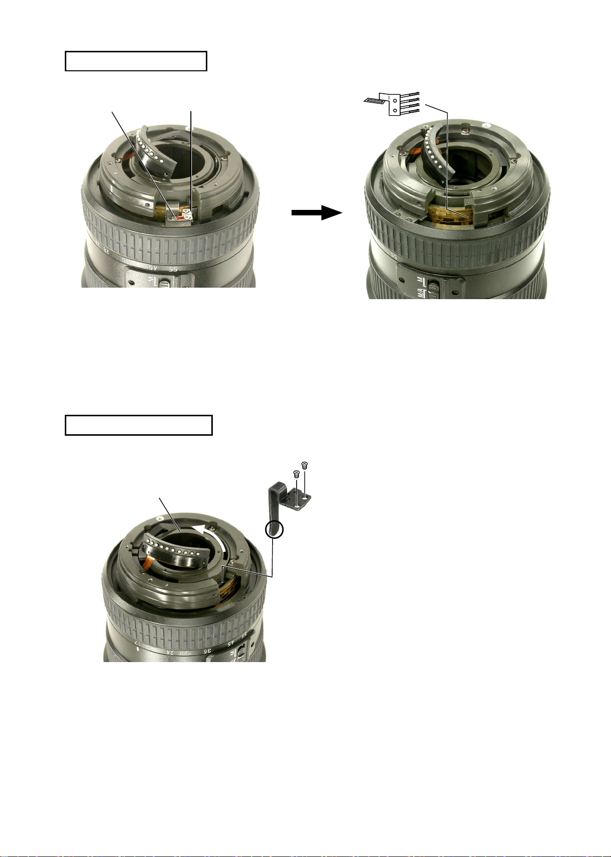
ZOOM ENCODER BRUSH
INC
#96×2
Zoom encoder brush
JAA78851-R.3617.A
Zoom encoder brush
Fig.1
Set the zoom ring to 17 mm, and take out 2 screws (#96). (ref. Fig.1)
・
Set the zoom ring to 28 mm, and remove the zoom encoder brush. (ref. Fig.2)
・
ZOOM CONNECTING PLATE
Cam ring
#59
#184×2
Fig.2
Set the zoom ring to WIDE-end.
・
Take out 2 screws (#184) to remove the
・
zoom connecting plate.
- L6・AF-S DX17-55/2.8G -
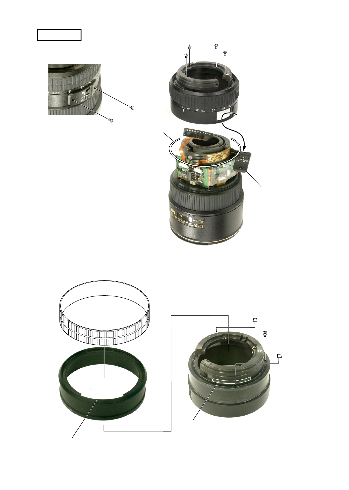
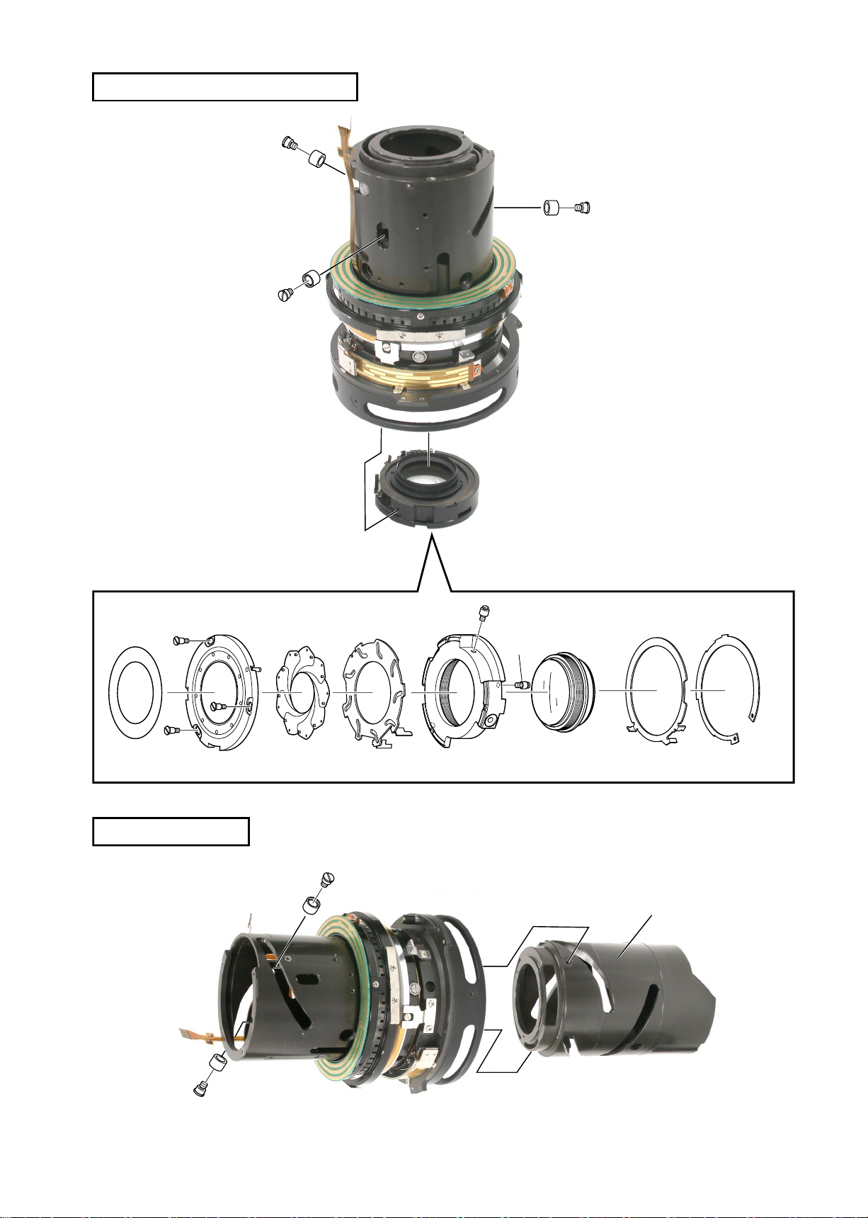
ZOOM RING
INC
#188×2
Take out 4 screws (#115) to remove the
・
zoom ring unit.
Pass the switch part of M/A selector
・
switch through the hole of the zoom
ring unit.
Remove the washer (#169).
・
JAA78851-R.3617.A
#115×4
Zoom ring unit
#169
M/A selector switch
Zoom ring
Zoom ring rubber
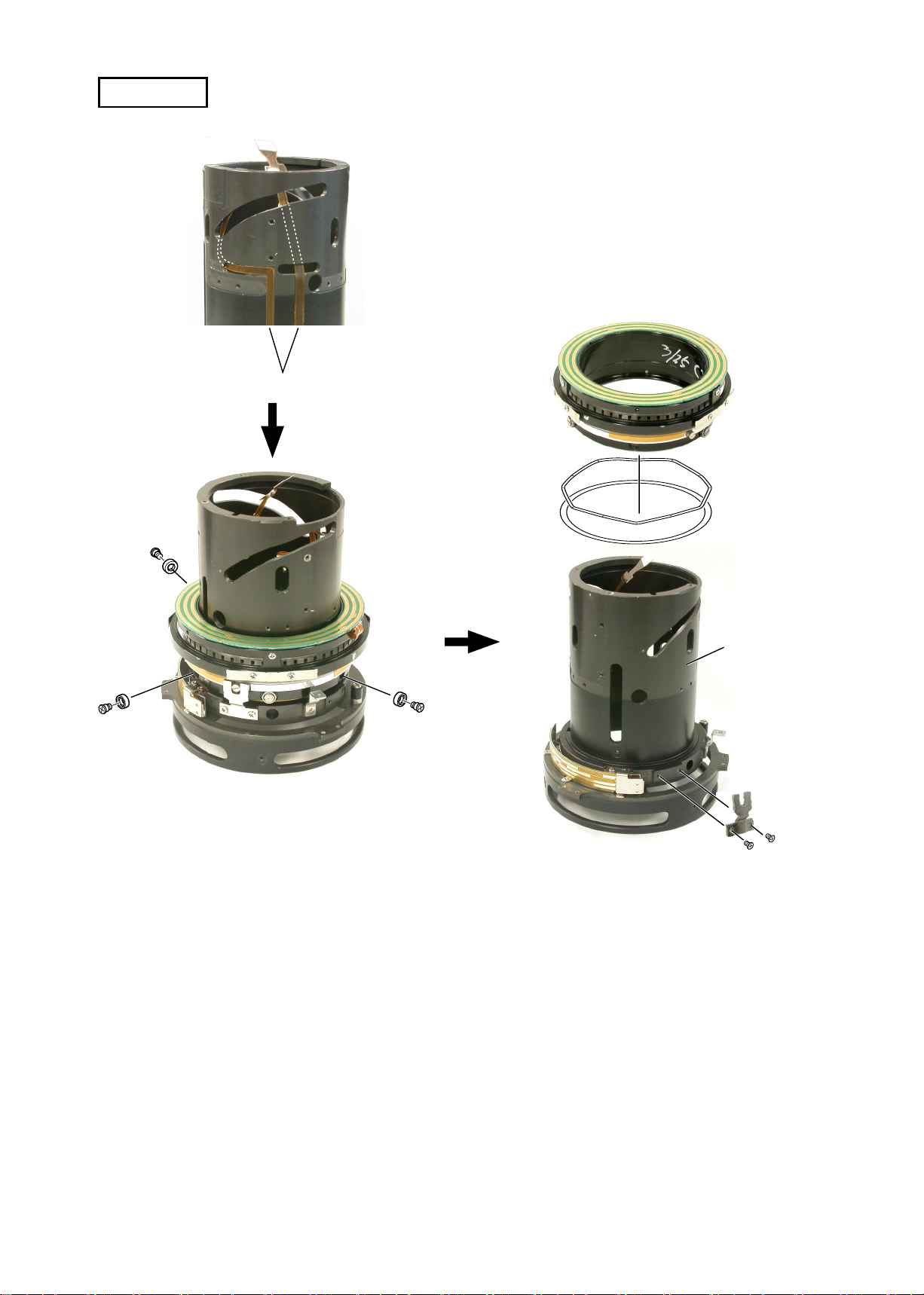
・
・
Protrusion
Take out the screw (#131).
Align the notch of the zoom ring with
the protrusion of the rear xed tube, and
remove the zoom ring from the rear xed
tube.
#131
#67×2
Rear xed tube
Notch
- L7・AF-S DX17-55/2.8G -
JAA78851-R.3617.A
INC
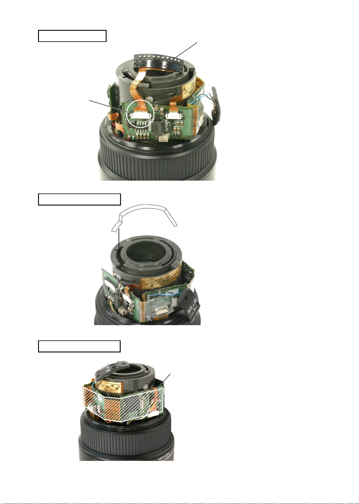
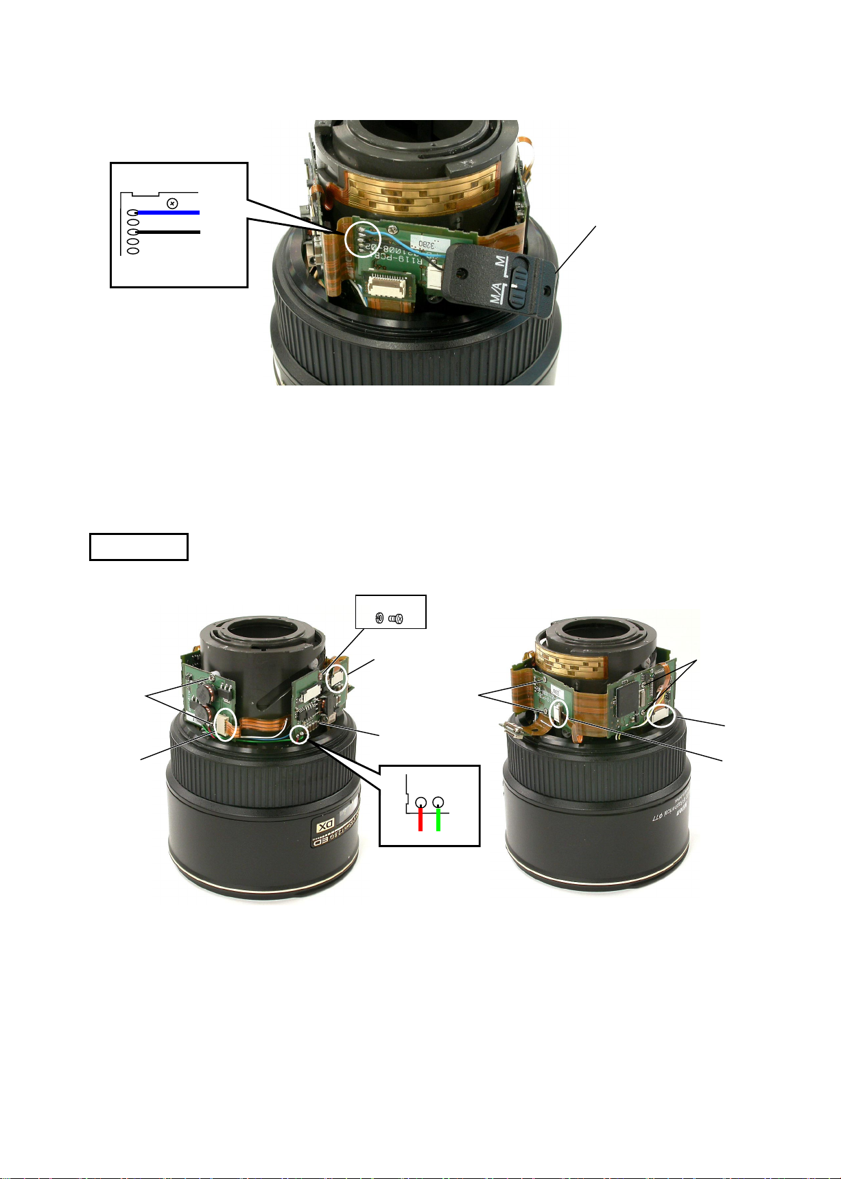
AF CONTACT UNIT
A
LIGHT-SHIELDING SHEET
AF contact unit
・
Remove the AF contact unit from
the connector A of the main PCB.
M/A SELECTOR SWITCH
#200
Tape
Peel off the light-shielding sheet
・
(#200).
Remove the tape of the main PCB.
・
- L8・AF-S DX17-55/2.8G -
JAA78851-R.3617.A
INC
MAIN PCB
Fig.1
Blue
Black
・
(ref. Fig.1)
#134
M/A selector switch
Unsolder 2 parts, and remove the M/A selector switch.
#133
#174×2
A
B
#173×2
#173
Red
Unsolder 2 parts. (ref. Fig.2)
・
Remove 4 connectors (A-D).
・
Take out the screw (#133) and 5 screws (#173) and 2 screws
・
Green
Fig.2
#173×2
C
D
(#174) to remove the main PCB.
- L9・AF-S DX17-55/2.8G -
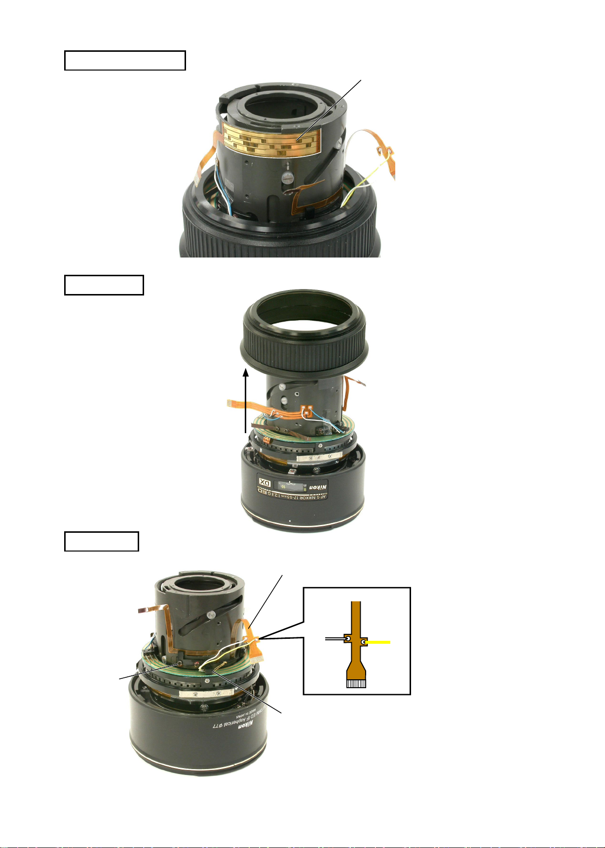
ZOOM ENCODER FPC
INC
FOCUS RING
Zoom encoder FPC
Peel off the zoom encoder FPC.
・
Focus ring
JAA78851-R.3617.A
M/A BRUSH
#49×2
Distance encoder brush
White
M/A Brush
Remove 2 wires of the distance encoder FPC.
・
Yellow
Fig.1
(ref. Fig.1)
Take out 2 screws (#49) to remove M/A brush.
・
- L10・AF-S DX17-55/2.8G -
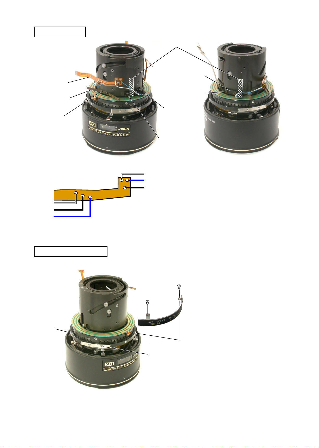
POWER BRUSH
INC
B3
#85
#79×2
White
Black
Blue
Fig.1
White
Blue
Black
JAA78851-R.3617.A
Tape
B63
#49×2
B63
#49×2
Remove 2 pieces of tapes that x the wire of the
・
power brush.
Unsolder 6 wires of the power brush. (ref. Fig.1)
・
Take out 2 screws (#49) to remove the power brush
・
B63(at 2 parts).
Peel off the FPC B3.
・
Take out 2 screws to remove the spring (#85).
・
DISTANCE SCALE PLATE
SWM
#62×2
Distance scale plate
Take out 2 screws (#62) to remove
・
the distance scale plate.
- L11・AF-S DX17-55/2.8G -
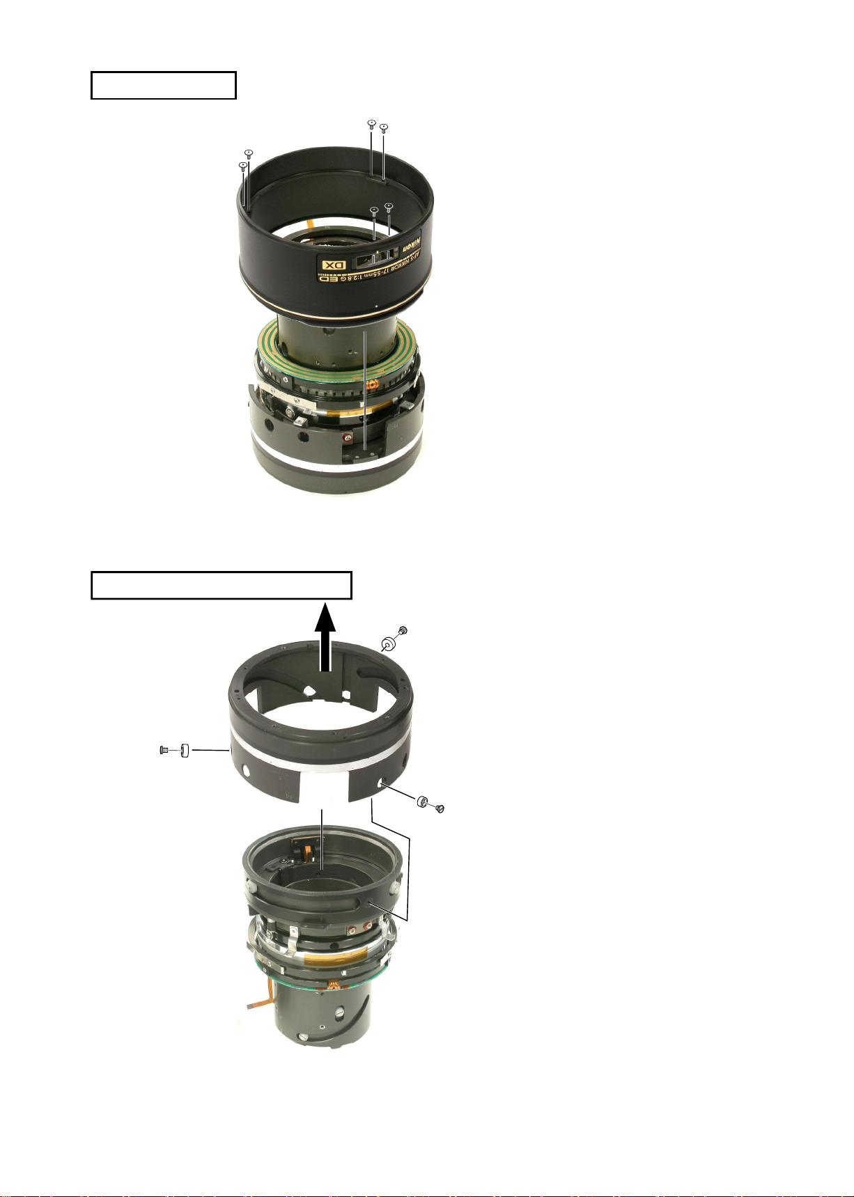
HOOD-FIX TUBE
INC
#166×6
Hood-x tube
JAA78851-R.3617.A
Take out 6 screws (#166) to remove
・
the hood-x tube.
1ST LENS GROUP STRAIGHT RING
1st lens group
straight ring
#192×3
#191×3
Pull up the 1st lens group straight ring
・
in the direction indicated by the arrow,
then take out 3 screws (#191) and 3
rollers (#192) to remove the 1st lens
group straight ring.
- L12・AF-S DX17-55/2.8G -
FOCUS SLIDING UNIT
INC
#75×2
#73×2
JAA78851-R.3617.A
Take out 2 screws (#75) to remove 2 levers (#73).
・
#48
Take out 3 screws (#80) to remove #48.
・
Take out 2 screws (#130) to remove #164. (ref. Fig. 1
・
#164
#52
#89×3
#116×3
#87×3
#80×3
#130×2
Fig.1
)
#164
- L13・AF-S DX17-55/2.8G -
#52
INC
Cam ring
#90×3
#82×3
JAA78851-R.3617.A
Turn the cam ring almost all the way to the
・
limit in the direction of the arrow so that
the roller mounting hole of the cam ring
can be seen.
Take out 3 screws (#82) and 3 rollers (#90)
・
to remove #52.
2.5TH LENS GROUP
2.5th lens group
#92×2
#83×2
#81×2
#81×2
#107
#103
Take out 2 screws (#83) and 2 rollers
・
2.5th lens group
(#92) to remove the 2.5th lens group.
- L14・AF-S DX17-55/2.8G -
APERTURE BLADE HOUSING UNIT
INC
#91×3
#86×3
JAA78851-R.3617.A
#205
#114×3
B17
CAM RING GROUP
B9×9
#93×2
#33
#84×2
B47
Aperture blade housing unit
#106
#106
3rd lens group
#101
Cam ring
#102
- L15・AF-S DX17-55/2.8G -
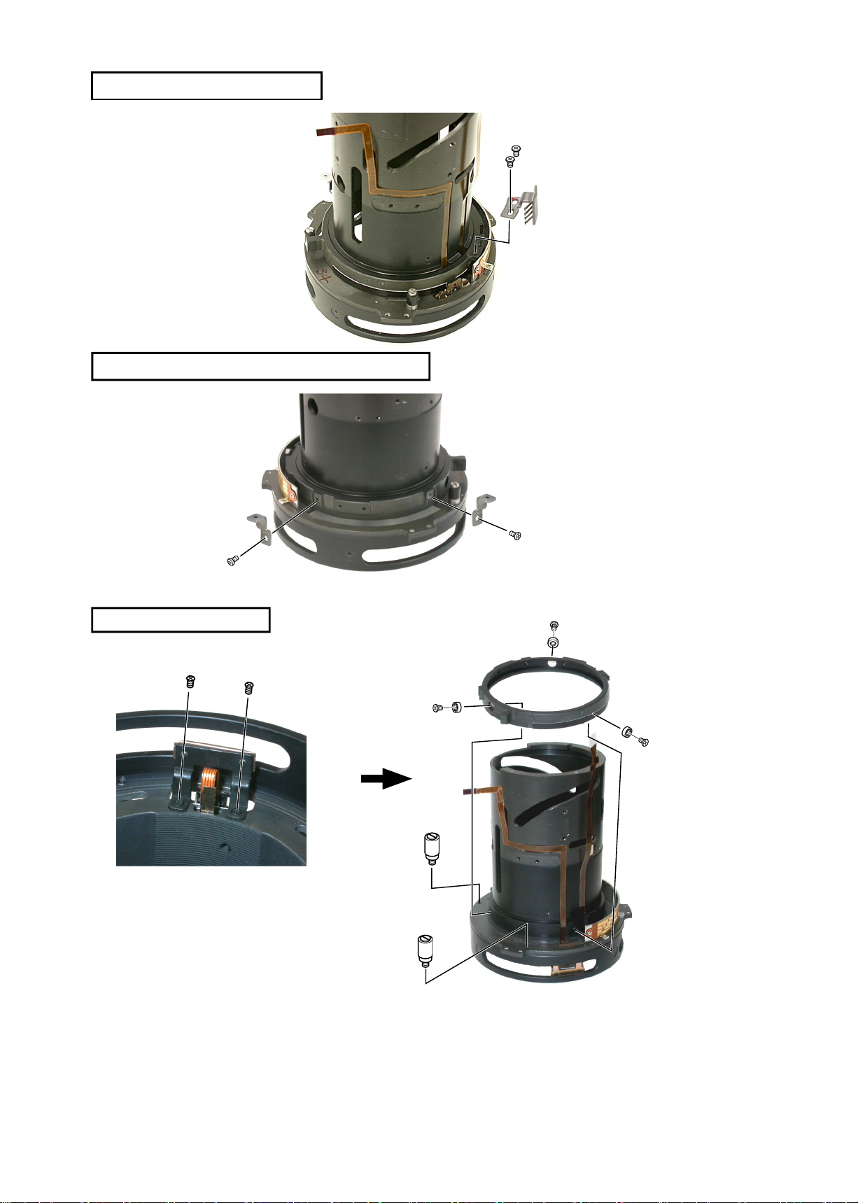
SWM UNIT
INC
Fig.1
Body
JAA78851-R.3617.A
Pass the FPC through the hole as shown in Fig.1, and
・
put it into the lens body in position.
Fig.2
FPC
SWM
#161
#160
#159×3
#158×3
#162
Fig.3
Take out 3 screws (#158) and 3 rollers (#159). (ref. Fig.2)
・
Remove the SWM, the washer (#160) and the wave washer (#161).
・
#100×2
(ref. Fig.3)
Take out 2 screws (#100) to remove the SWM connecting key (#162).
・
(ref. Fig.3
Take out the FPC which was put into the lens body.
・
)
- L16・AF-S DX17-55/2.8G -
DISTANCE ENCODER BRUSH
INC
DISTANCE SCALE PLATE MOUNTING-BASE
JAA78851-R.3617.A
#99×2
Distance encoder brush
MAGNETIC TAPE UNIT
#124×2
Fig.1
#61×2
#100×2
Magnetic tape unit
#194×3
#72×3
Stopper screw
Stopper screw
Take out 2 MR head xing screws (#124). (ref. Fig.1)
・
to prevent damage on the magnetic tape unit
(
Take out 3 screws (#72) and 3 rollers (#194) to remove the
・
)
magnetic tape unit.
Take out the 2 stopper screws.
・
- L17・AF-S DX17-55/2.8G -
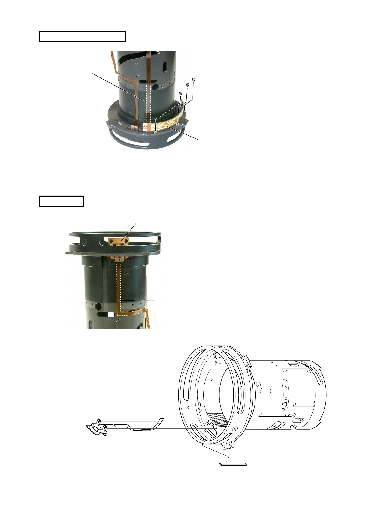
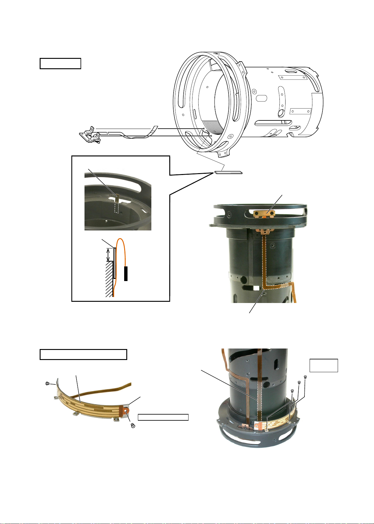
DISTANCE ENCODER FPC
INC
FPC
JAA78851-R.3617.A
#197×3
Take out 3 screws (#197) to remove the
・
distance encoder FPC.
Peel off part of the FPC shown by broken line.
・
Distance encoder FPC
MR HEAD
Fig.1
MR head
FPC
Peel off part of the FPC shown by
・
broken line. (ref. Fig.1)
Remove the MR head. (ref. Fig.2)
・
MR head
Fixed ring
Fig.2
#127
- L18・AF-S DX17-55/2.8G -
ASSEMBLY
INC
MR HEAD
MR head
#127
JAA78851-R.3617.A
Fixed ring
#127
MR head
#127
6mm
Fixed ring
Attach #127 on the xed tube. (ref. Fig.1)
・
Attach MR head FPC. (ref. Fig.2)
・
Do not screw the MR head at this stage.
FPC
MR head
Fig.1
DISTANCE ENCODER FPC
Distance encoder FPC
Attach the FPC along the
broken lines.
#196
Fig.2
Attach the FPC along the broken lines.
Adhesive:
Lock end B
#197×3
Adhesive: Lock end B
Fig.3
Attach the distance encoder FPC on #196 by aligning it with the screw hole for #193, then tighten 2
・
#193×2
Fig.4
screws (#193). (ref. Fig.3)
Mount #196, on which the distance encoder FPC was attached, on the xed tube, then tighten 3 screws
・
(#197). (ref. Fig.4)
- L19・AF-S DX17-55/2.8G -
MAGNETIC TAPE UINIT
INC
#195×2
#132×2
Adhesive:Lock end B
Fig.1
Magnetic tape unit
#194×3
#72×3
Adhesive:Lock end B
・
・
・
・
JAA78851-R.3617.A
Adhesive:Lock end B
#124×2
Fig.2
Assemble the magnetic tape unit into the xed tube.
(ref. Fig.1)
Note: Do not damage MR head and magnetic tape.
Attach 3 screws (#72) and 3 rollers (#194).
Attach 2 screws (#132) and 2 stopper rubbers (#195).
Fix the MR head with 2 screws (#124). (ref. Fig.2)
INSPECTION AND ADJUSTMENT FOR THE WAVEFORM OUTPUT FROM MR ENCODER
● In case of disassembling or replacing the MR head, be sure to make an adjustment.
1. Equipment and tools required
・Single output rated voltage power supply: 1 unit With 5.0V and 100mA, applicable to the self-
made tool
・Oscilloscope: 1 unit
・
Note:
Self-made tool: 1 unit
In case of any trouble in continuity between the self-made tool and the contacts of relay
FPC, there may be dust, corrosion or oxidation on the contact surface of relay FPC. Be
sure to polish the contact surface before getting connected to the self-made tool
.
2. Preparation for measuring lens
・Connect the xed tube, on which the MR head and magnetic tape unit were attached, to the
measuring devices. (Refer to the next page.)
- L20・AF-S DX17-55/2.8G -
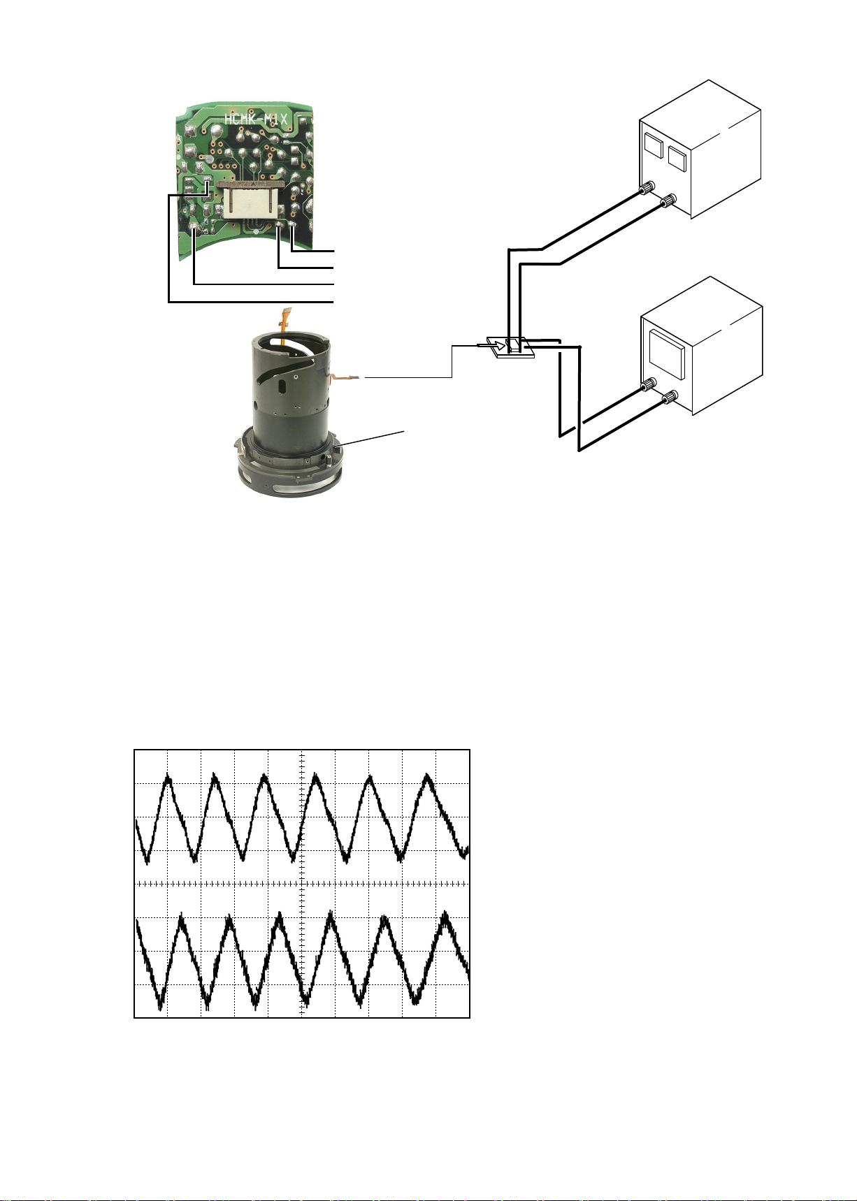
C H 1= 2 0 m V CH2 = 2 0 mV 5 m s/d i v
AC 1 0: 1 AC 10 :1
NOR M 200 KS/ s
Connection diagram
INC
・
JAA78851-R.3617.A
Power supply
Self made tool
(GND)
(+)
Oscilloscope(2ch)
Oscilloscope(1ch)
Power supply(+)
Power supply(-)
Self made
tool
Magnetic tape unit
Set values
5.0V
100mA
Oscilloscope
(2ch)
・How to make an inspection and adjustment
Make sure that the current and voltage of the connected rated voltage power supply are set values.
①
Then, turn the power on.
② Set the oscilloscope and turn the magnetic tape unit by hand.
Note:Because the shape of waveform varies according to the driving speed of magnetic tape unit, set
Time/Div accordingly.
In case of detecting any wide waveform noise, use the lter function.
③
How to set the ler function by Yokogawa-manufactured DL1540
1.
Press the lter button.
2.
Select "Smooth" in the menu on the PC screen.
CH1
CH2
Standard:The amplitude of every pulse/waveform should be 50mV or more.
●Setting of oscilloscope
V/Div(CH1)
V/Div(CH2)
Coupling
Time/Div
Trigger Mode
Trigger Coupling
Trigger Source
Trigger Position
Trigger Type
Trigger Level
INPUT (ch1)
INPUT (ch2)
20 mV
:
20 mV
:
AC
:
5 m Sec
:
NORMAL
:
AC
:
CH1
:
4div
:+
EDGE
:
0 V
:
AC
:
AC
:
Note:Check the waveform by letting the focus ring to travel from the innity-end to the near
distance-end and vice versa.
- L21・AF-S DX17-55/2.8G -
C H 1= 2 0 m V CH2 = 2 0 mV 5 m s/d i v
AC 1 0: 1 AC 10 :1
NOR M 200 KS/ s
C H 1= 2 0 m V CH2 = 2 0 mV 5 m s/d i v
AC 1 0: 1 AC 10 :1
NOR M 200 KS/ s
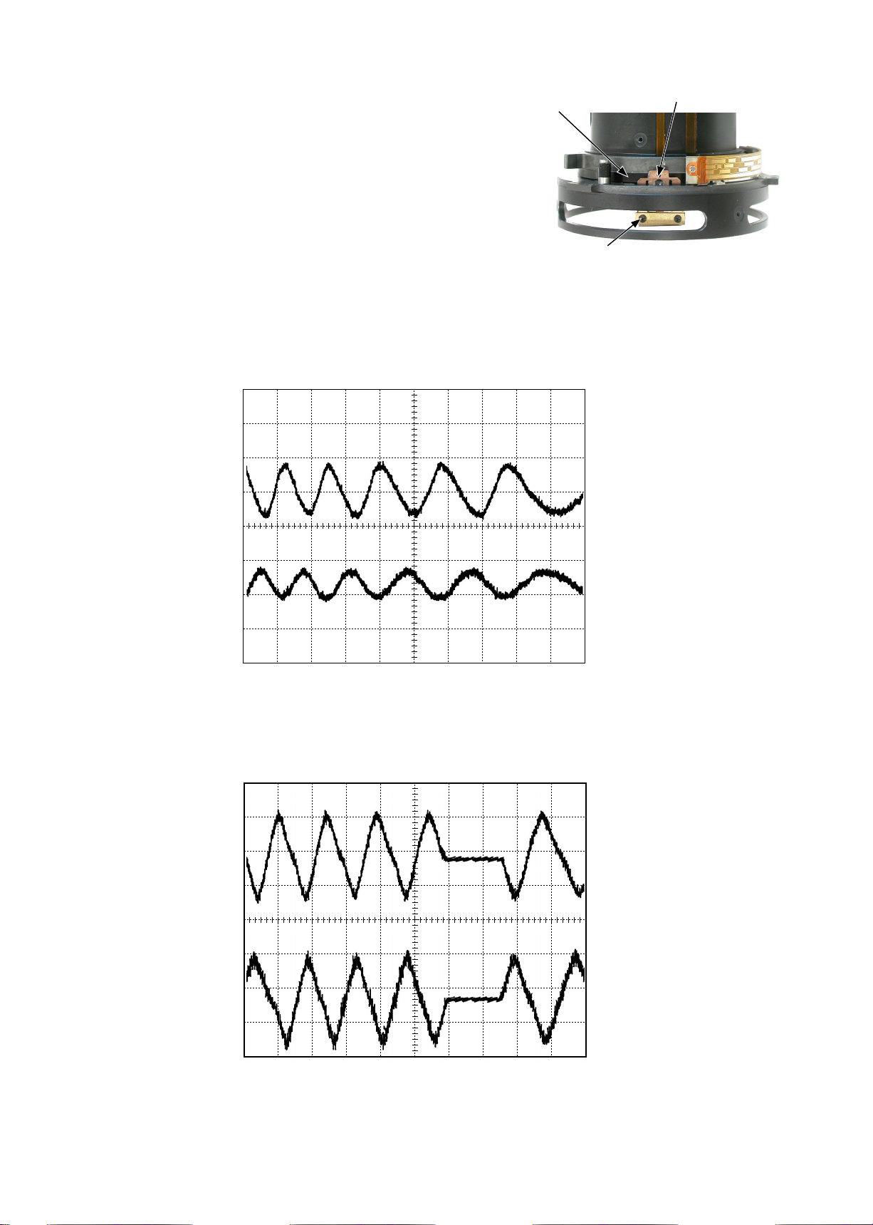
④ In the case of smaller amplitude, loosen 2 screws (#123)
INC
to move the MR head for adjustments as shown in Fig.1.
Note: During adjustment, prevent the magnetic tape and
MRhead from touching the magnetized driver bit.
Otherwise, the magnetic data may be damaged.
Magnetic tape
JAA78851-R.3617.A
MR Head
#123×2
Fig.1
《Reference》
● In case the amplitude of either CH1 or CH2 is smaller, one of 2 screws (#123) may be loosened,
so check for it. But if this is not the case, the MR head is regarded as malfunctioning. Be sure to
replace the MR head unit and adjust it again.
CH1
CH2
●In case there is a partial drop in the amplitude between the innity and the near distance, the magnetic
data of magnetic tape may be damaged. Then, replace the magnetic tape and adjust it again.
CH1
CH2
Fig.2
Fig.3
⑤ Turn off the rated voltage power supply.
- L22・AF-S DX17-55/2.8G -
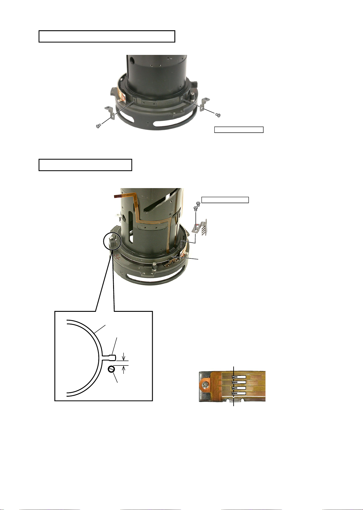
DISTANCE SCALE PLATE MOUNTING-BASE
INC
DISTANCE ENCODER BRUSH
JAA78851-R.3617.A
#61×2
#100×2
Adhesive:Lock end B
Magnetic tape unit
Protrusion
2mm
Adhesive:Screw Lock
#99×2
Distance encoder brush
Magnetic tape unit
Attach the distance encoder brush on the magnetic tape unit
・
with temporarily 2 screws (#99).
Turn the magnetic tape unit so that the distance between
・
the protrusion and stopper rubber (#132) becomes 2-mm.
(ref. Fig.1)
Adjust so that the contact face of the brush becomes the
・
reference position (ref. Fig.2). After tightening 2 screws
(#99), apply Screw lock.
Fig.1
#132
Fig.2
Reference position
- L23・AF-S DX17-55/2.8G -
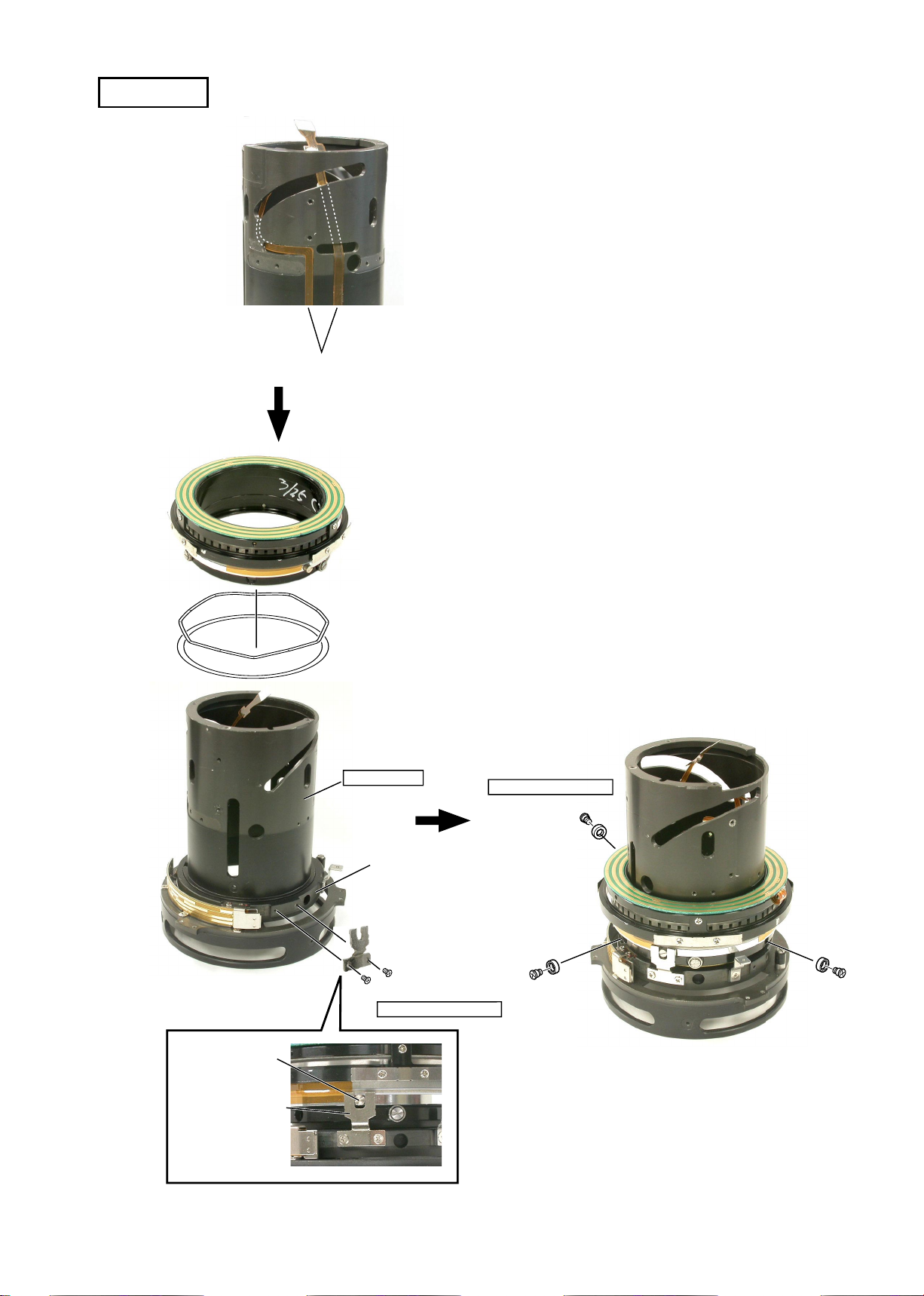
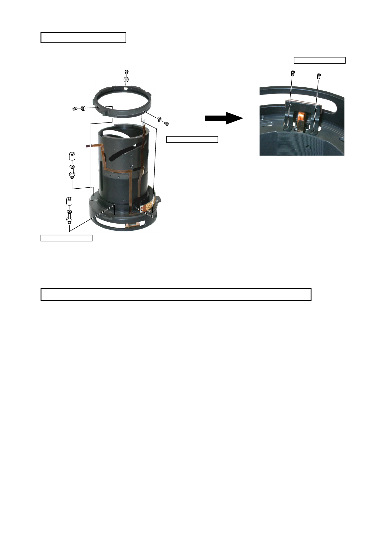
SWM UNIT
INC
Fig.1
FPC
#161
SWM
Body
JAA78851-R.3617.A
Pass the FPC through the hole as shown in Fig.1, and
・
put it into the lens body in position.
Attach the SWM connecting key (#162) to the
・
magnetic tape unit with 2 screws (#100).
Put the washer (#160) and wave washer (#161) on.
・
Assemble the SWM and engage the shoulder screw
・
of the SWM in the SWM connecting key. (ref. Fig.2)
Attach 3 screws (#158) and 3 rollers (#159). (ref.
・
Fig.3)
Take out the FPC which was put into the lens body.
・
Shoulder screw
#160
Cam grooves (2 parts)
Large vertical grooves (2 parts)
Small vertical grooves (3 parts)
Grease:GE-8
Magnetic tape unit
#162
#100×2
Adhesive:Lock end B
Adhesive:Lock end B
#158×3
#159×3
Fig.3
SW M co nnecting
key
Fig.2
- L24・AF-S DX17-55/2.8G -
 Loading...