

Nikon ED 12-24 Repair manual

JAA78451-R.3596.A
作成承認印
配布許可印
REPAIR MANUAL
NIKON CORPORATION
Tokyo, Japan
Recycled paper
Printed in Japan March 2003
Copyright c 2003 by Nikon Corporation.
All Rights Reserved.
AF-S DXZoom-Nikkor ED 12-24mm f/4G IF
INC

JAA78451-R.3596.A
- M1
・ AF-S DX12-24/4G
-
Type of lens
Focal length
Maximum aperture
Lens construction
Picture angle
Focal length scale
Distance information
Zoom control
Focusing
Shooting distance scale
Closest focus distance
Diaphragm
Aperture range
Exposure measurement
Attachment size
Dimensions
Weight
G-type AF Zoom- Nikkor lens having built-in CPU and Nikon F bayonet mount
12mm - 24mm (18 - 36 mm in 35 mm format)
f/4
11 elements in 7 groups (3 aspherical lens and 2 ED lens elements)
99° - 61° (with Nikon Digital Camera D1/D1H/D1X/D100)
12,15,18,20,24mm
Output to camera body
Manually via separate zoom ring
Nikon Internal Focusing (IF) system (utilizing an internal Silent Wave Motor);
manually via separate focus ring
Graduated in meters and feet from 0.3m (1ft.) to innity (∞)
0.3m (1ft.) at all zoom settings
Fully automatic
f/4-22 at all zoom settings
Via full-aperture method with cameras having CPU interface system
77mm (P=0.75mm)
Approx. 82.5mm dia. ×90mm extension from the camera's lens mount ange
Approx.485g
SPECIFICATIONS
This lens can be used for Nikon digital SLR camera only.
INC
JAA78451-R.3596.A
- L1・ AF-S DX12-24/4G -
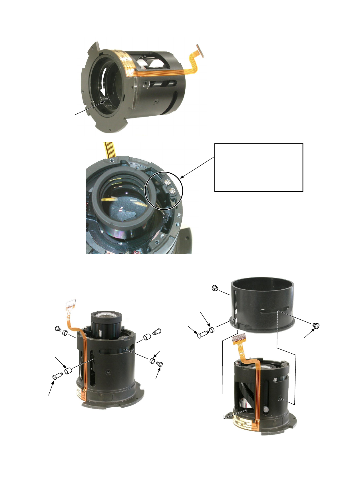
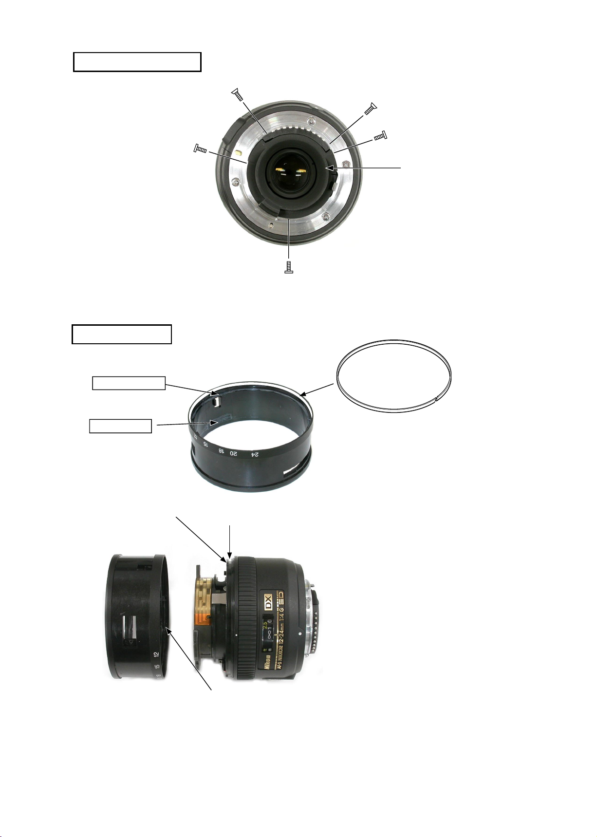
Disassembly
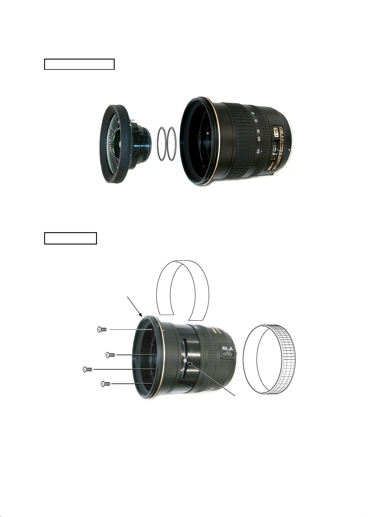
1ST LENS GROUP
#101
FILTER RING
#103
#35
#79
#104×4
・
Remove the rubber ring (#35).
・
Remove the blindfolding-cover (#103).
・
Unscrew #79.
・
Take out 4 screws (#104).
・
Remove the lter ring.
Filter ring
INC

JAA78451-R.3596.A
- L2・ AF-S DX12-24/4G -
REAR COVER RING
#64×2
#66×3
ZOOM RING
#87
B4
#66
・
Unscrew #87.
・
Unscrew #66.
・
Remove the encoder brush (B4).
・
Remove the zoom ring.
Note
:
The convex 3 parts of the zoom ring are
grooved in #22.
So remove the zoom ring by turning it to
the position where the convex parts detach
from the groove.
Rear cover ring
Zoom ring
Groove
Convexity
#22
#127
INC

JAA78451-R.3596.A
- L3・ AF-S DX12-24/4G -
BAYONET
#100
#109×3
#110
INDEX RING, FOCUS RING
Index ring
Focus ring
M/A change-over
SW
M/A change-over
SW
・
Detach the M/A change-over SW from the index ring
by sliding it as shown in Fig. 1.
・
Remove the index ring.
・
Remove the focus ring.
Note
:
Pass the M/A change-over SW through the hole of
the index ring as shown in Fig. 2.
Fig. 1.
Index ring
Fig. 2.
INC
JAA78451-R.3596.A
- L4・ AF-S DX12-24/4G -
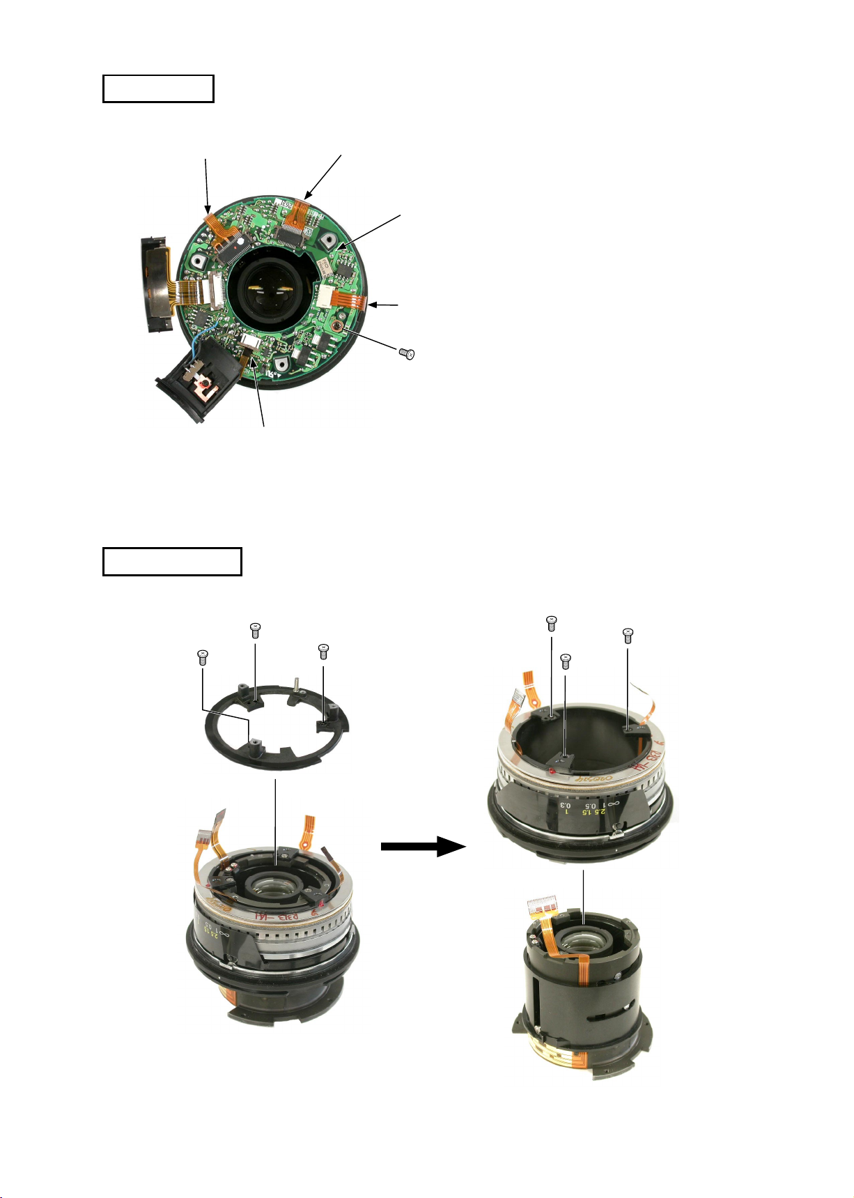
MAIN PCB
Distance encoder FPC
Main PCB
Zoom encoder FPC
SWM-FPC
MR sensor FPC
・
Remove the FPCs (positioned at 4 parts)
from the connecter.
・
Unscrew #89.
・
Remove the main PCB.
SWM UNIT
#89
#90×3
#29
#90×3
SWM unit
INC
JAA78451-R.3596.A
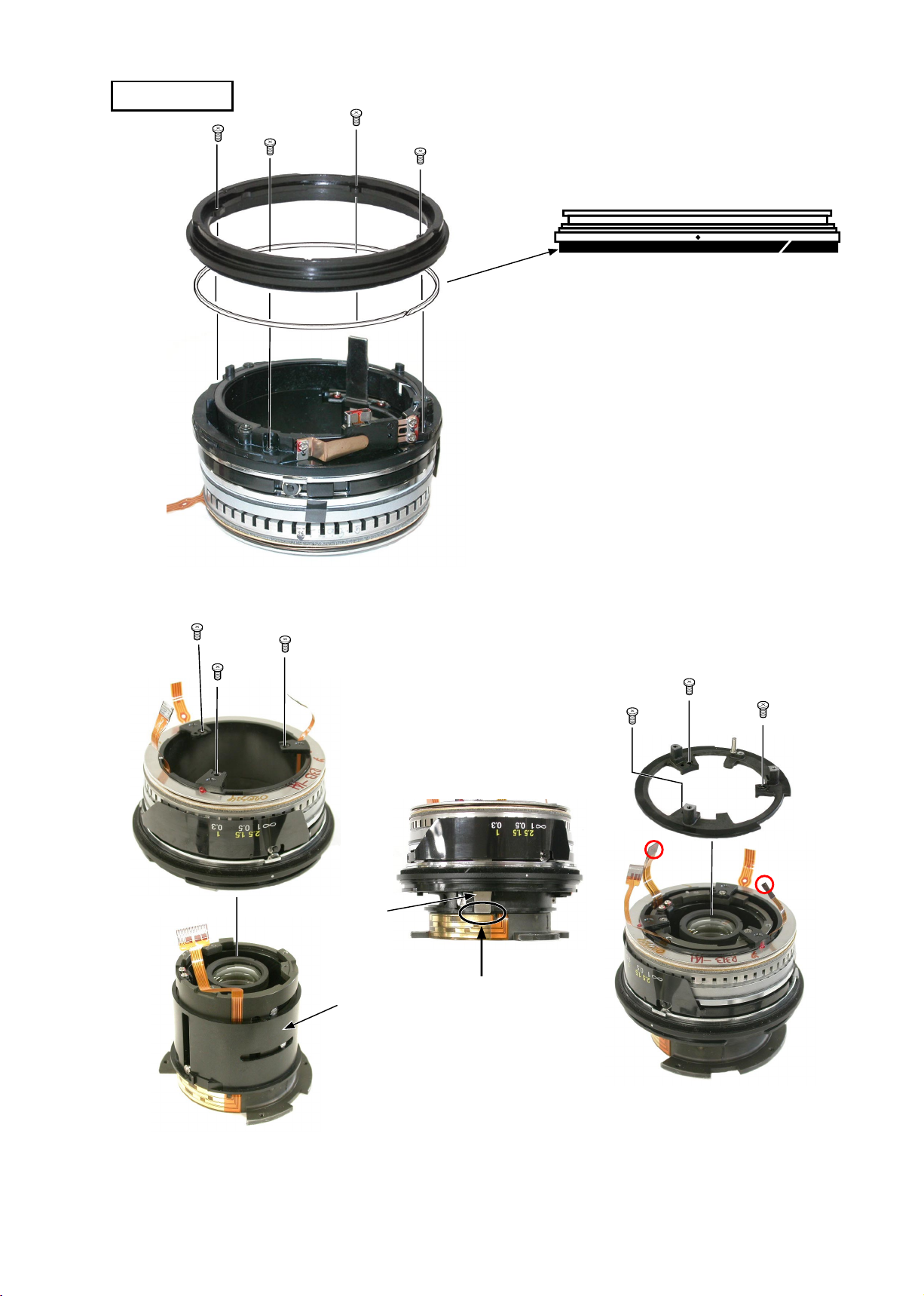
- L5・ AF-S DX12-24/4G -
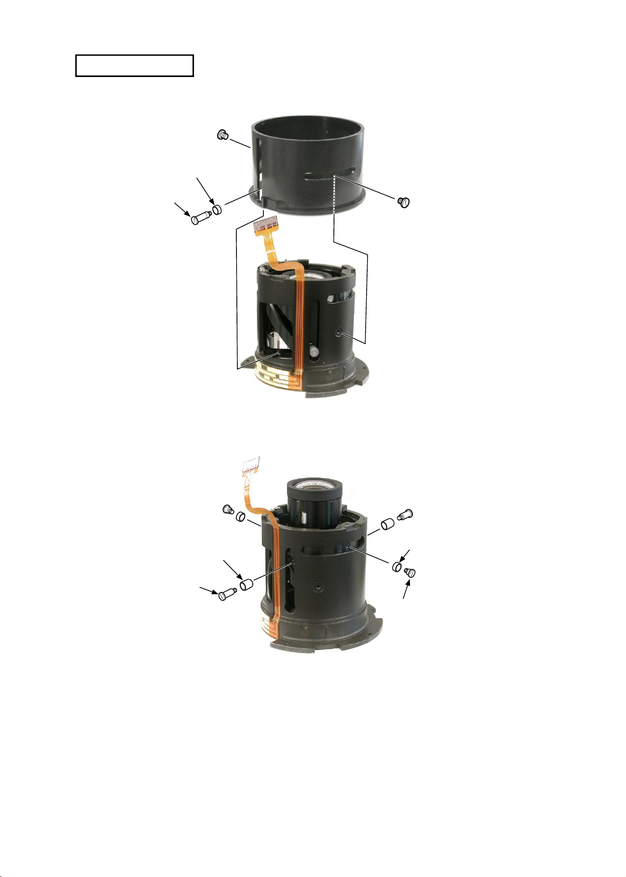
#86
#77
#72
#78 × 2
#98 × 2
#97 × 2
#84 × 2
#72 × 2
CAM RING UNIT
INC

JAA78451-R.3596.A
- L6・ AF-S DX12-24/4G -
・
Take out the cam ring by turning the
1st sliding ring in the direction indicated by the arrow.
・
Detach the 2nd and 3rd units from
the cam ring.
1st sliding ring
Cam ring
Can ring
2nd and 3rd units
1st sliding ring
#96×3
#135×3
#95×3
INC

JAA78451-R.3596.A
- L7・ AF-S DX12-24/4G -
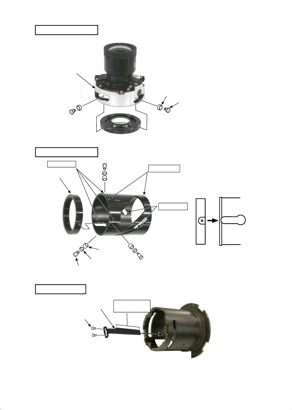
2ND LENS GROUP
#84×2
#72×2
2nd lens group
3RD LENS GROUP
3rd lens group
Aperture blade housing
#68×3
Note
:
If the 3rd lens group is removed, the shaft alignment is necessary
after assembling.
If the shaft alignment is impossible in your service ofces, do not
remove the 3rd lens group.
INC

JAA78451-R.3596.A
- L8・ AF-S DX12-24/4G -
Assembly
3RD LENS GROUP
3rd lens group
Aperture blade housing
#68 × 3
APERTURE BLADE HOUSING UNIT
Aperture blade housing unit
B5 × 7
#56
#33
#52
#59 × 2
#58
#60
#59 × 2
#80 × 2
#58
#60
#80
#80
#56
#52
#33
#59
#59
INC
JAA78451-R.3596.A
- L9・ AF-S DX12-24/4G -
2ND LENS GROUP
#84×2
#72×2
2nd lens group
・
Apply the grease (GE-8) to 3
parts of the cam groove and
the all-round of #34.
1st sliding ring
#96×3
#135×3
#95×3
1ST SLIDING RING
・
Apply the grease (GE-8) to 5 parts of
the cam groove and across stepped
parts.
・
Assemble the 1st sliding ring at the
below position.
LIMIT PLATE
#69×2
Limit plate
1st sliding ring
Cam ring
Cam ring
#34
Grease: GE-8
Grease: GE-8
Grease: GE-8
Grease: MZ-800S
INC

JAA78451-R.3596.A
- L10 ・ AF-S DX12-24/4G -
ZOOM ENCODER FPC
Attach the FPC along the groove.
Align the end of FPC in this position.
Do not let the FPC run off downwards.
CAM RING UNIT
Cam ring
2nd and 3rd group units
・
Insert the 2nd and 3rd group units
into the cam ring in the position as
shown in the left.
・
Insert the cam ring by aligning it with
the 3 guide rollers and 3 notches of
#51.
Notch
#51
Guide roller
Cam ring
・
Apply the grease (GE-8) to the cam
grooves (3 transversal grooves and 2
longitudinal grooves.).
・
Apply the grease (GE-8) to 3 inside
cam grooves.
Inside cam groove
Attach with Super glue
INC
JAA78451-R.3596.A
- L11 ・ AF-S DX12-24/4G -
・
Turn the 1st sliding ring in
the direction indicated by the
arrow.
1st sliding
ring
#86
#77
#72
#78×2
Make sure that the limit plate is
entered in the notches of the 2nd
and 3rd group units.
#98×2
#97×2
#84×2
#72×2
・
Apply the grease (MZ-800S) to
the 1 longitudinal groove and 3
transversal grooves of #86.
INC

JAA78451-R.3596.A
- L12 ・ AF-S DX12-24/4G -
POSITION ADJUSTMENT OF LIMIT PLATE
Limit plate
#69
#29
#90×3
#109×3
Bayonet
・
Fix the limit plate in the center.
・
As shown in Fig. 1., assemble #29 and the
bayonet.
The aperture lever (#55) is put into A of Fig.
2.
#55
Fig. 1.
A
Fig. 2.
・
Turn the zoom to TELE side.
(to the position where the 2nd and 3rd lens units are
pushed downward.)
・
Move the aperture lever slowly in the direction indicated
by the arrow, and make sure of being the full aperture
when the aperture blades stop.
Make adjustments by changing the position of attaching
the limit plate.
・
After adjusting, apply the Screw Lock to #69.
・
Remove #29 and the bayonet.
Aperture lever
2nd and 3rd group units
INC

JAA78451-R.3596.A
- L13 ・ AF-S DX12-24/4G -
SWM unit
#541 × 2
#534
#533
#543
#536
・
Attach the
MR
head so that it is
aligned parallel to the magnetic tape.
・
Attach the
MR
sensor FPC so that
it goes alongside the inside groove of
the SWM unit.
INSPECTION AND ADJUSTMENT FOR THE WAVEFORM OUTPUT FROM MR ENCODER
●In case of disassembling or replacing the MR head, be sure to make adjustments.
1. Equipment and tools to be required
・Single output rated voltage power supply: 1 unit With 5.0V and 100mA, applicable to the
self-made tool
・Oscilloscope: 1 unit
・Self-made tool: 1 unit
Note:In case of any trouble in continuity between the self-made tool and the contacts of relay FPC,
there may be dust, corrosion or oxidation on the contact surface of relay FPC. Be sure to
polish the contact surface prior to connect to the self-made tool.
2. Preparation for the measuring lens
・Set the SWM unit on which the MR head is already set, the MF ring, the rear xing tube, and
the index ring into the cam ring unit. Then connect to the measuring devices. (Refer to the next
page.)
Note: When make checks and adjustments, put a cloth under the lens to avoid any damages to the
rear lens.
Magnetic tape
MR sensor FPC
MR head
MR HEAD
INC

JAA78451-R.3596.A
- L14 ・ AF-S DX12-24/4G -
#90×3
Rear xing
tube
#90×3
SWM unit
Insert the focus
connection key
into the groove of
#86.
#86
Focus
connection
key
Index ring
MF ring
Pass this FPC through the
hole of the index ring.
INC

JAA78451-R.3596.A
- L15 ・ AF-S DX12-24/4G -
・
Connections
(GND)
( + )
C H 1 = 2 0 m V C H 2 = 2 0 m V 5 m s / d i v
AC 10 : 1 A C 10 : 1
NO RM 20 0K S/ s
● Oscilloscope setting
V/Div (ch1) :
20mV
V/Div (ch2) :
20mV
Coupling :
AC
Time/Div :
5m
Sec
Trigger Mode :
NORMAL
Trigger Coupling :
AC
Trigger Source :
CH1
Trigger Position :
+4
div
Trigger Type :
EDGE
Trigger Level :
0V
INPUT (ch1) :
AC
INPUT (ch2) :
AC
Standard:The amplitude of every pulse/waveform should be 50mV or more.
Note:Check the waveform by letting the focus ring to travel from the innity-end position to
the near distance end position and vice versa.
・How to conduct inspection and adjustment
①
Make sure that the current and voltage of the connected rated voltage power supply are set values.
If they meet the set values, turn on the power.
② Set the oscilloscope and drive the focus ring by hand.
Note:Since the shape of waveform varies according to the driving speed of focus ring, particularly and properly set
Time/Div.
③
In case of detecting any wider waveform noise, use the lter function.
How to set the ler function in the employment case of Yokogawa-manufactured DL1540
1.Press the lter button.
2.Select "Smooth" in the menu on the PC screen.
Oscilloscope
(2ch)
Oscilloscope
(1ch)
Power supply
(+)
Power supply
(-)
Self-made tool
Oscilloscope
(2ch)
Set values
5. 0V
100mA
Self-made tool
Power supply
INC

JAA78451-R.3596.A
- L16 ・ AF-S DX12-24/4G -
④ In the case of smaller amplitude, for adjustment, loosen
the two screws #541 and then shift the MR head position
as shown in the right gure.
Note
:During adjustment, prevent the magnetic tape and MR
head from touching the magnetized driver bit, or the magnetic
data may be damaged.
● In case of a presence of partial drop in the amplitude between the innity and the near distance, the magnetic data
in magnetic tape may be damaged. Then, replace the magnetic tape and adjust it again.
《Reference》
● In case the amplitude of either CH1 or CH2 seems smaller, one of the two screws #541 may be loosened.
Then, check the screws. In case the screws are fully tightened, the MR head may be troubled. Then, be sure to
replace the MR head unit B15 and adjust it again.
⑦ Turn off the rated voltage power supply and remove the SWM unit. P
# 541 × 2
MR head
Magnetic tape
C H 1 = 2 0 m V C H 2 = 2 0 m V 5 m s / d i v
AC 10 : 1 A C 10 : 1
NO RM 20 0K S/ s
C H 1 = 2 0 m V C H 2 = 2 0 m V 5 m s / d i v
AC 10 : 1 A C 10 : 1
NO RM 20 0K S/ s
INC
JAA78451-R.3596.A
- L17 ・ AF-S DX12-24/4G -
SWM UNIT
#90×3
#29
#90×3
SWM unit
#88
#22
#131×4
・
Attach #88 to #22, and apply the oil
barrier to the overall #88.
・
Build #22 in the SWM unit.
・
Tighten 4 screws (#131
)
.
#22
SWM
Insert the focus
connecting key into
the groove of #86.
#86
Focus
connecting
key
Pass the circled FPC through
the inside of #29.
INC

JAA78451-R.3596.A
- L18 ・ AF-S DX12-24/4G -
MAIN PCB
Distance encoder FPC
Main PCB
Zoom encoder FPC
SWM-FPC
MR sensor FPC
・
Attach the main PCB.
・
Screw #89.
・
Connect the FPC (at 4 parts) to the
connector.
#89
Index ring
M/A change-over
SW
INDEX RING, FOCUS RING
Focus ring
#75
・
Attach #75 to the focus ring, and apply the oil barrier
to the overall #75.
・
Assemble the focus ring by aligning the inside notches
(at 3 parts) and the projections of SWM (at 3 parts).
・
Assemble the index ring by passing the M/A change-
over SW unit through the hole of the index ring.
Projection
On the sliding surface with focus
ring.
Grease: MZ-800S
INC

JAA78451-R.3596.A
- L19 ・ AF-S DX12-24/4G -
M/A change-over SW
Index ring
・
Slide the M/A change-over SW and
assemble into the index ring.
BAYONET
#100
#109×3
#110
・
Put the aperture lever
(
#55
)
in A
of the above.
A
#55
J18004-1
POSITION ADJUSTMENT OF APERTURE LEVER
Aperture lever
#93×2
・
Turn the zoom to the TELE side.
(
to the position where the 2nd and 3rd
lens units are pushed downward.
)
・
Attach the tool (J18004-1) and make
sure of the aperture diameter.
Standard: Full aperture
・
In case it is out of standard, adjust the
position of the aperture lever by loos
-
ening 2 screws (#93).
・
After adjusting, x the 2 screws (#93)
with Screw Lock.
INC
JAA78451-R.3596.A
- L20 ・ AF-S DX12-24/4G -
ZOOM RING
Zoom ring
Groove
Convexity
#22
Zoom ring
#105
・
Attach #105 to the zoom ring, and
apply the oil barrier to the overall
#105.
・
Put the convexities (at 3 parts) inside
the zoom ring in the notches (at 3
parts) of #22, to assemble together.
All-round
3 convexities
REAR COVER RING
#64×2
#66×3
Rear cover ring
Grease: MZ-800S
Grease:GE-8
INC

JAA78451-R.3596.A
- L21 ・ AF-S DX12-24/4G -
#79
#104×4
Filter ring
FILTER RING
・
Put the convexity of the leter ring in the notch of the above, and
attach the lter ring with 4 screws (#104).
Notch
Convesity (on backside)
All-round
Filter ring
Grease: GE-8
INC

JAA78451-R.3596.A
- L22 ・ AF-S DX12-24/4G -
#G1
#42
#41
#102
#126 × 2
B1
#101
#G2.3
● The size of 2 washers (#126) is xed (0.038mm).
1ST LENS GROUP
#87
B4
#66
#127
・
Turn the zoom to the TELE side.
・
Attach the encoder brush (B4) in the
above position and x it with screw
(#66).
After adjusting,x #66 with the Screw
Lock.
Position to attach the encoder brush
ZOOM ENCODER BRUSH
RUBBER RING
#35
#103
Attach with Screw Lock
INC

JAA78451-R.3596.A
- L23 ・ AF-S DX12-24/4G -
Focal length
(f)
Standard
(mm)
12mm -0.05~+0.10
18mm -0.05~+0.10
24mm -0.05~+0.10
ADJUSTMENT (DIVISION) OF FOCUS MOVEMENT (T, W)
1.Fit the innity ( ∞ ) mark of the focus ring to the index.
2.Fix the aperture lever to make the aperture "full".
3.Read the values of the Wide and Tele sides.
4.Carry out the following calculations.
A - B = C A= Value of Tele side
B= Value of Wide side
C= Adjustment amount (mm) of the 2nd lens group unit washer #101
5.Adjust the thickness of the washer #101 by the value of C calculated in the above. If C is positive, thicken the
washer. If it is negative, thin the washer.
Note:When setting the washer #101, put a thin washer between thick washers.
ADJUSTMENT OF BACK FOCUS
1.Fit the innity ( ∞ ) mark of the focus ring to the index.
2.Fix the aperture lever to make the aperture "full".
3.Read the value of Wide or Tele side.
4.Remove the bayonet mount.
5.Adjust the thickness of the washer #100 by the difference from the standard value. If the difference value is
positive, thicken the washer. If it is negative, thin the washer.
INC
JAA78451-R.3596.A
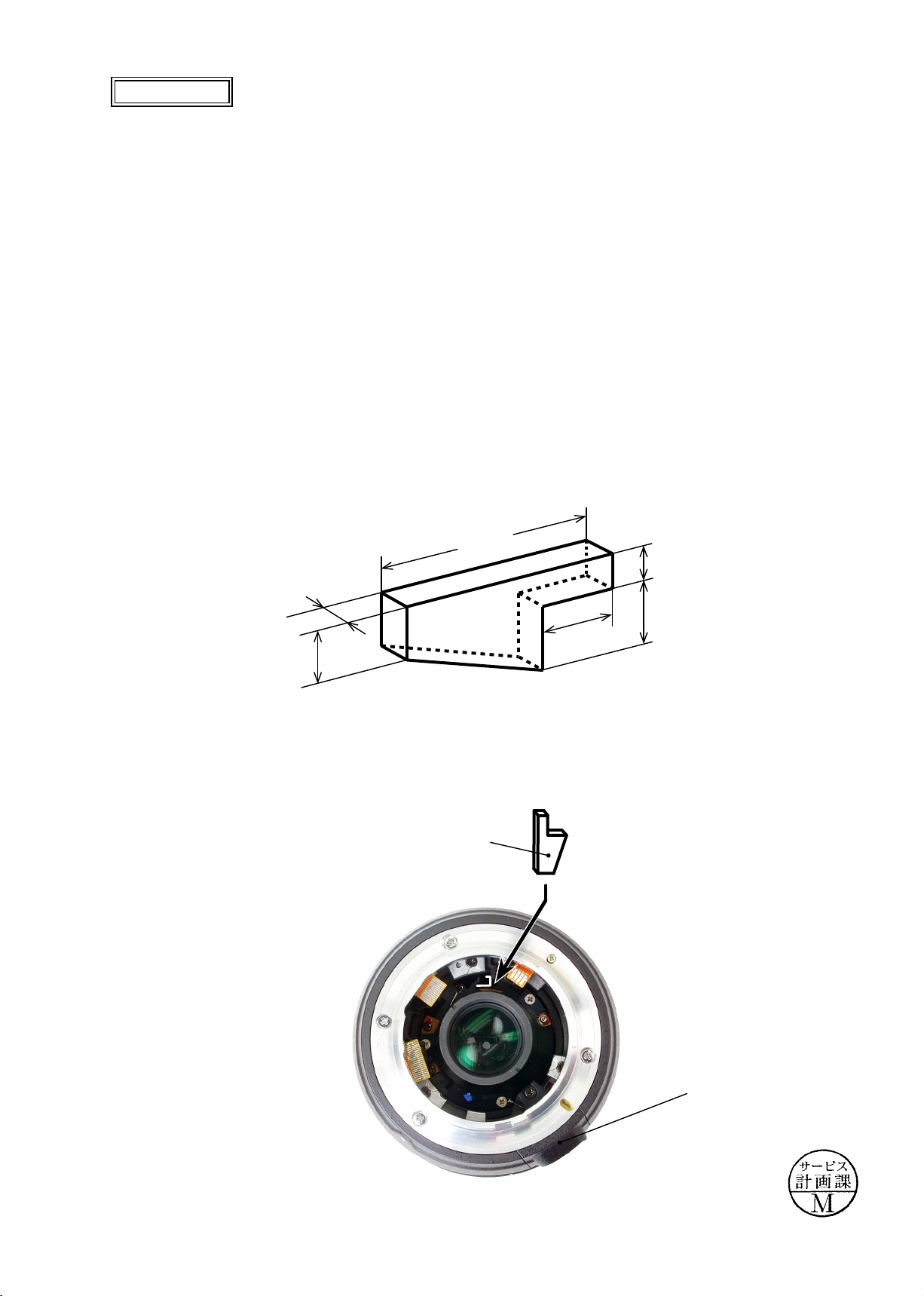
- L23-1・ AF-S DX12-24/4G -
Added page
July. 01. 2005
Note: This adjustment is required when the 3rd lens groups is removed.
(1) Preparation of Lens to be examined
・
Remove the main PCB on Page L2-L4.
・
Remove the aperture lever of the bayonet mount.
・
Remove the solder of wires (blue and black) of M/A change SW from the main PCB.
・
Assemble the other parts, but exclude the main PCB, aperture lever, and rear cover ring.
・
Create an aperture opening tool for (AF-S DX12-24/4G).
Procedure
①
Prepare one piece of rubber (17mm x 7.5mm x 2mm).
(Note) Choose relatively exible material of rubber that can be easily cut, because it is used for putting
in the clearance between the lens aperture lever and lens chamber.
②
Cut the rubber sheet (17mm x 7.5mm x 2mm) into the below size.
・
By using the above created tool, set the lens to full aperture opening.
17.0mm
4.0mm
2.0mm
7.0mm
2.5mm
5.0mm
M/A change SW
Lens alignment
Aperture opening tool
INC
JAA78451-R.3596.A
- L23-2・ AF-S DX12-24/4G -
Added page
July. 01. 2005
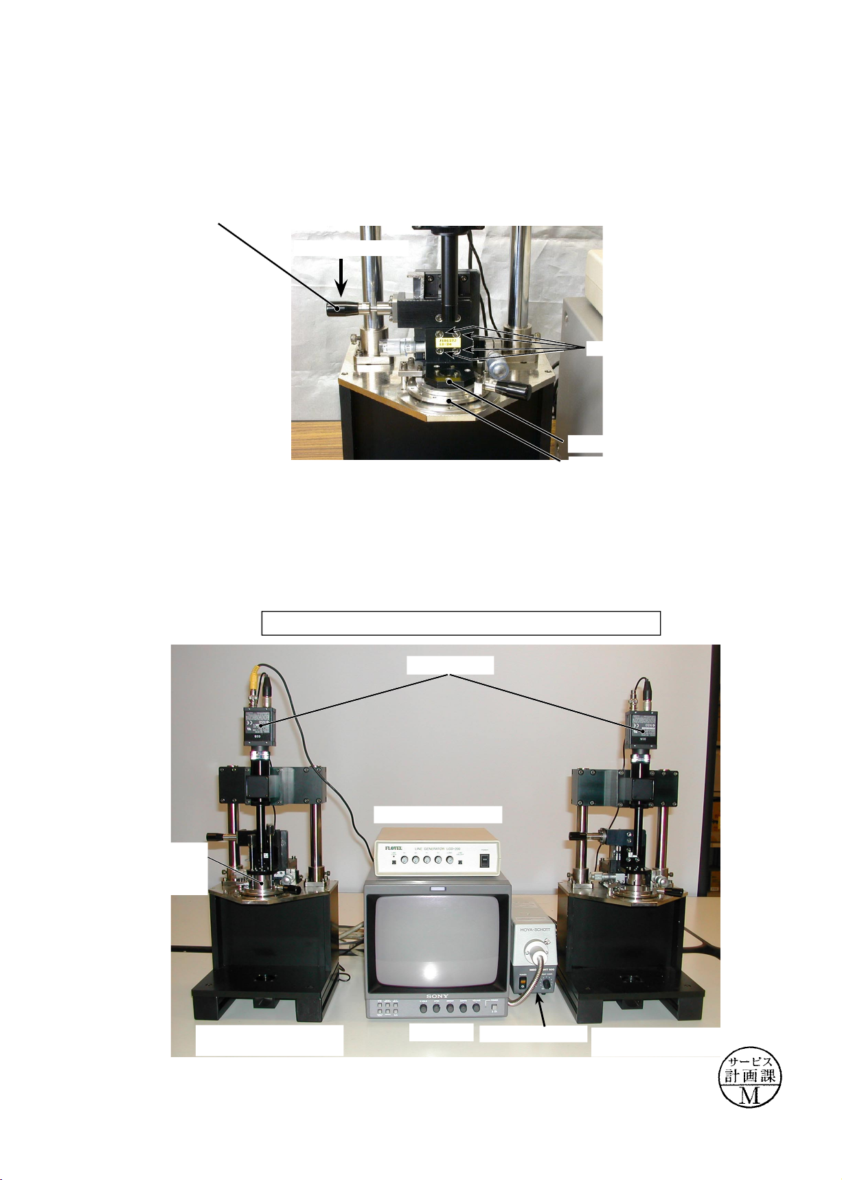
(2) Preparation of Lens optical alignment equipment
・
Fix the attachment holder for the 3rd lens group (J19127J) in the lens equipment for center alignment.
How to x: Move down the holder-moving lever slowly so that the holder touches the stage. Then tighten 4
screws to x it.
・
Create the center positioning tool (ref. Page L23-13 for how to create it).
・
Create setting boards in which "Lens alignment chart" and "Viewers" are t. (ref. Page L23-15 for how
to create them.)
Holder-moving lever
Move down slowly
Holder for 3rd lens group (J19127J)
Stage
Screw×4
Lens alignment
equipment (for periphery)
Monitor
LINE GENERATOR
MEGALIGHT 100
Attachment
holder for 3G
(J19127J
)
CCD camera
Lens optical alignment equipment for center (left) and periphery (right)
Lens alignment equipment
(for center)
INC
JAA78451-R.3596.A
- L23-3・ AF-S DX12-24/4G -
Added page
July. 01. 2005
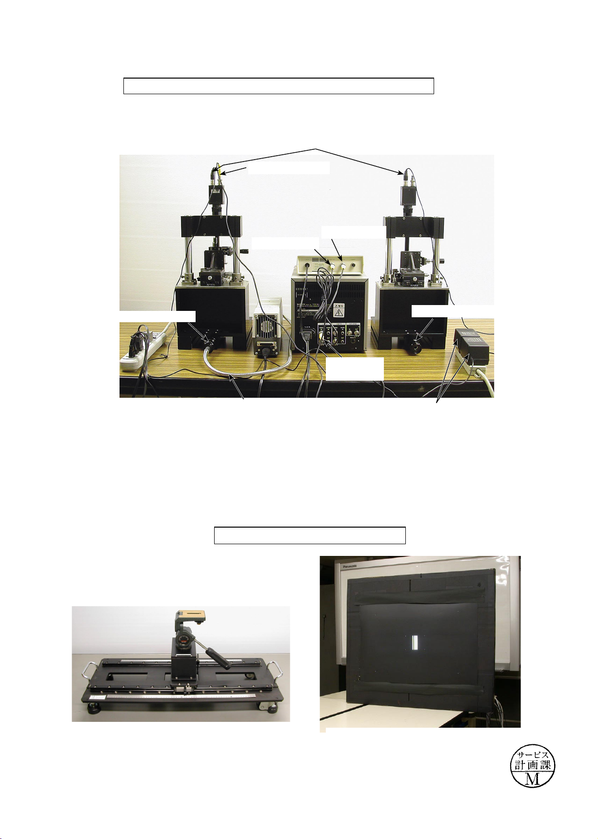
①
VIDEO cable
‘①VIDEO IN
②
VIDEO OUT
Back view of Lens optical alignment equipment for center and periphery
・
Connect each cable to the appropriate equipment with the same number. (e.g. Connect up
①
to‘
①
.)
④
Power cable for CCD camera
‘
②
"VIDEO
IN" of LINE A
③
Fiber-optic cable
‘‘
③
Pinhole chart
‘
④
AC power for CCD camera
‘
③
Cross line chart
Chart shooting equipment for Lens alignment
Slide rail for Lens alignment equipment
The chart is embeddied in blackened cardboards.
INC
 Loading...