

Page 1

M368E 05.10.NF.1
Microscope
ECLIPSE FN1
Instructions
Page 2

Page 3
Introduction
Thank you for purchasing the Nikon product.
This instruction manual is written for the users of the Nikon Microscope ECLIPSE FN1. To ensure correct usage,
please read this manual carefully before operating the product.
• It is prohibited to reproduce or transmit this manual in part or whole without Nikon's expressed permission.
• The contents of this manual are subject to change without notice.
• Although every effort has been made to ensure the accuracy of this manual, if you note any points that are
unclear or incorrect, contact your nearest Nikon representative.
• Some of the products described in this manual may not be included in the set you have purchased.
• Also be sure to read the manuals for any other products that you are using with this system (the super
high-pressure mercury lamp power supply, high-intensity light source, and such).
WARNING and CAUTION Symbols Used in This Manual
Although Nikon products are designed to provide the utmost safety during use, incorrect usage or failure to follow the
safety instructions provided may cause personal injury or property damage. Damage or injury that may occur due to
mishandling is unwarranted. To ensure correct usage, read the instruction manual carefully and thoroughly before
using the product. Do not discard the manual; keep it handy for easy reference.
Safety instructions within this manual are accompanied by the following symbols to highlight their importance. For
your safety, always follow the instructions accompanying these symbols.
Symbol Meaning
WARNING
CAUTION
Disregarding instructions accompanying this symbol may lead to serious injury or
death.
Disregarding instructions accompanying this symbol may lead to injury or property
damage.
1
Page 4
Introduction
Meaning of the symbol used on the product
The symbol appearing on the product indicates the need for caution at all times during use. Always refer to the
instruction manual and read the relevant instructions before manipulating any part to which the symbol has been
affixed.
Caution for heat
This symbol on the lamphouse of the Eclipse FN1 calls your attention on the following:
• The lamp and its surroundings (including the lamp house) become very hot during and
immediately after lighting.
• Do not touch the lamp and its surroundings during and immediately after lighting to prevent
the risk of burns.
• Make sure that the lamp and its surroundings are sufficiently cool before the lamp
replacement.
2
Page 5

Safety Precautions
Take note of the following points to use this product and its system safely and correctly.
1 Intended product use
2 Do not disassemble
3 Read the instructions carefully
4 Cautions about the power cord
WARNING
This microscope system is intended primarily for microscopy and photomicrography of specimens such as
sliced living cells using the dia illumination or the epi illumination.
Disassembling the microscope or the microscope system may result in electric shock or malfunctions.
Malfunctions and damage due to disassembling are unwarranted.
Never attempt to disassemble any part other than the parts described in this manual. If you experience
problems with the microscope or the microscope system, contact your nearest Nikon representative.
To ensure safety, carefully read this manual and the manuals provided with any other equipment used with
this microscope. In particular, observe all warnings and cautions given at the beginning of each manual.
To use this microscope system with an epi-fl attachment:
The mercury lamp (or xenon lamp) used for the epi-fl microscopy requires special handling. Make sure to
see the manual provided for either the super high-pressure mercury lamp power supply or the
high-intensity light source.
Make sure to use the specified power cord. Using a wrong power cord may result in malfunctions or fire.
The power supply for this system is classified as subject to Class I protection against electrical shock.
Make sure the power supply unit is connected to an appropriate ground terminal (protective earth
terminal).
Refer to Chapter 7, "Specifications," for the specified power cord.
To prevent electrical shock, always turn off the power switch (press it to the "O" position) on the power
supply unit before attaching or detaching the power cord.
5 Cautions about heat from the light source
The lamp and its surroundings (including the lamp house) become very hot during and immediately after
lighting.
• Do not touch the lamp and its surroundings during and immediately after lighting. They become very
hot and may cause burn injuries.
• Make sure that the lamp and its surroundings are sufficiently cool before the lamp replacement.
• Do not allow cloth, paper, or highly flammable volatile materials, such as gasoline, benzine, paint
thinner or alcohol, to come near the lamp house while the lamp is lit or within 30 minutes after
switching off the power. They become very hot and may cause fire or burn injuries.
3
Page 6

Safety Precautions
WARNING
6 Mercury lamp or xenon lamp
(for an epi-fl attachment)
The mercury lamp (or xenon lamp) used for the epi-fl attachment requires special handling. To use the
system safely and correctly, read the warnings below and be aware of the dangers. Also carefully read
the manual for the super high-pressure mercury lamp power supply (or high-intensity light source) and
the manual (if provided) by the manufacturer of the lamp and follow their instructions.
Warnings about the mercury lamp and the xenon lamp
1) The mercury lamp (or the xenon lamp) radiates ultraviolet light that is harmful to the eyes and skin
when the lamp is turned on. Don't look at the lamp directly. Direct viewing of light from these lamps
may result in blindness.
2) Gas is sealed under very high pressure inside the lamp. The pressure increases when the lamp is on.
If the lamp is scratched, dirty, subjected to high external pressure or physical impact, or used beyond
its operational life, the sealed gas may escape or the lamp may burst. In such cases, there is a
possibility of inhaling the gas, injury by broken piece of the glass, or other accidents.
3) When the lamp is on, the lamp and its surroundings become extremely hot. Do not tough the lamp
and its surroundings to prevent a burn injury and do not place flammable materials near the lamp to
prevent a fire.
4) Use only the lamps specified in this manual. Using other than the specified type of lamp could
result in an accident, such as a burst.
Because safety is a top priority in the design of Nikon products, the hazards described above should not
pose any danger as long as you heed all of the warnings and cautions in the manuals and use the system
only for its intended purpose. However, the hazards described above could lead to an accident if you fail
to heed all of the warnings and cautions in the manuals, if you strike the system, or if you attempt to
disassemble the system. Therefore, always be sure to heed all of the warnings and cautions.
7 Turn off the lamp before changing the filter cubes
(for an epi-fl attachment)
Before changing the filter cubes, be sure to turn off the light source of the epi-fl attachment. If the lamp is
lit and the filter cubes are changed, dangerous ultraviolet rays may be radiated.
8 Place the D/UV slider into the optical path
(for the D-FL epi-fl attachment)
To perform the bright-field microscopy under the episcopic illumination, the dark-field microscopy under
the episcopic illumination, or the DIC microscopy under the episcopic illumination with the mercury lamp
house, place the D/UV slider of the D-ES EPI ND slider into the optical path. If the D/UV slider is removed
from the optical path, dangerous ultraviolet rays will be radiated and the eyes and skin may be injured.
9 Installation of the microscope
To prevent the microscope from toppling over, fix the microscope FN1 body securely on a baseplate or a
vibration isolator with bolts.
4
Page 7

Safety Precautions
CAUTION
1 Isolate this microscope and its system equipment from the power source during assembly,
connecting/disconnecting cords, lamp replacement, and maintenance
To prevent electric shock and/or malfunctions, always turn off the power switches for the system (press
them to the "O" positions) and unplug the power cords from the wall outlet before assembly, connecting or
disconnecting cords, lamp replacement, and cleaning the microscopy and the objectives.
2 Cautions when replacing lamps
To prevent burn injuries, wait at least 30 minutes after the lamp is turned off to give it sufficient time to cool
down when replacing lamps. And, to avoid electric shock or malfunctions, never attempt to replace lamps
without turning off the power switches for the system (press them to the "O" positions). And then, unplug
the power cords from the wall outlet.
Make sure the lamp house cover is securely fitted to the lamp house after replacing lamps. Never turn on the
lamp while the lamp house cover is open.
When you dispose of the replaced lamp, do not break it up. Instead, dispose of the used lamp as special
industrial waste or dispose of it according to the local regulations and rules.
3 Use the specified light source
Use the specified light source. Using a wrong light source may cause a malfunction or a fire.
• For the illumination with the optical fiber
Specified light source: Sumita Optical Glass Inc. Halogen light source LS-DWL-N
• For the illumination with the lamp house
Specified lamp house: Nikon FN-LH
Specified lamp: 12V 100W Long life halogen lamp (PHILIPS 7724i or ODRAM HLX 64623)
Specified power supply: Nikon TE2-PS100W
* In addition, when the lamp house is used for the illumination, a lamp house adapter must be
attached to connect the lamp house with the microscope FN1.
4 Do not spill water or a chemical agent onto the microscope system
Never allow water or a chemical agent to come into contact with the microscope system. And do not use
the microscope system in circumstances where the microscope system is splashed with water or a
chemical agent. Water or a chemical agent splashed onto the power supply or the power supply device for
the optical fiber light source may cause a short circuit, resulting in malfunction or abnormal overheat. If the
product is subject to contact with water or a chemical agent, turn off the power switches for the product
(press them to the "O" positions). Then unplug the power cords from the wall outlet. Then, wipe off the
water with a piece of dry cloth. If water or a chemical agent enters the product, do not use the product and
contact your nearest Nikon representative.
5 Do not place any object on the top of the microscope or its system
Do not place any object on the top of the microscope or its sytem. Do not cover them with a piece of cloth
or so on. The system temperature will rise, resulting in malfunctions.
5
Page 8

Safety Precautions
CAUTION
6 Cautions in assembling, installing, and carrying the microscope system
• Take care to avoid pinching your finger or hand during the microscope system assembly and
installation.
• Scratches or fouling such as fingerprints on optical components (lenses, filters, and so on) will
degrade microscope images. Be careful to avoid scratches or direct contact with the lenses and filters
when assembling the microscope system.
• To carry the microscope system, first detach all parts. And, tilt the microscope body while supporting
it, then securely hold it by the base.
• Never grasp the focus knobs, eyepiece tube, sliding nosepiece, nosepiece up/down part, stage,
substage, or condenser when carrying the microscope system. This may cause the part to come off,
resulting in damage to the microscope system.
• Do not install the product in a locker or a cabinet.
7 Do not turn on the power supply and the power supply for the optical fiber light source when a
cover is placed over the product.
Do not turn on the power supply and the power supply for the optical fiber light source when a cover is
placed over the product. A cover on the product blocks the heat radiation and it may cause abnormal heat
or fire hazards.
8 Cautions about long and continuous observations
To relieve fatigue resulting from long observation sessions, limit continuous observations to one hour.
Take at least 10- to 15-minute breaks between observation sessions. And, take care of the layout of
devices to be used and adjust the height of your chair.
6
Page 9

Notes on Handling the Microscope System
Notes on Handling the Microscope System
1 Handle with care
This microscope system is a precision optical instrument. Handle the microscope system with care to avoid
shock on impact.
In particular, objectives may loose accuracy when exposed to even a weak physical shock.
2 Weak electromagnetic waves
The power supply for this microscope system emits weak electromagnetic waves. There is a possibility that
some precision electronic devices are affected by the electromagnetic waves. To prevent bad influences,
locate such electronic equipment away from the microscope system. If a TV or radio reception is affected,
move the TV or radio set farther from the product.
3 Dirt on the lens
Scratches or fouling such as fingerprints on optical components (lenses, filters, and so on) will degrade
microscope images.
If these parts become dirty, clean them as described in Capter 6, "Care and Maintenance" at the end of this
manual.
4 Dirt on the lamp
Never touch the lamp with bare hands. Dirt or fingerprints on the lamp will result in uneven illumination and
reduce the service life of the lamp. Always wear gloves when handling lamps.
5 Installation location
This microscope system is a precision optical instrument. So, the usage or storage in an inappropriate
environment may result in malfunctions or poor performance. Consider the following factors when selecting
an installation location:
• Fix the microscope FN1 body securely on a baseplate or a vibration isolator with bolts.
• When the microscope is mounted on a microscope slider such as an XY mover, fix the microscope
body on the microscope slider securely with bolts or so on to prevent the microscope from toppling
over.
• The halogen lamp light source, the lamp house, and the optical fiber light source need to dissipate heat
when the lamp is lit. So, locate such heat sources at least 10 cm away from walls.
• Choose a location less exposed to hazards in the event of collisions, earthquakes, or other potential
disasters. Choose a sturdy vibration isolator, desk, or table for the base of the microscope system.
• Avoid bright locations where the product is exposed to direct sunlight or immediately under room lights.
If the ambient light is bright, the microscopy image will be affected.
• Choose a location that is free from considerable dust or dirt.
• To avoid splashes, do not use the microscope system near water.
• Make sure the ambient temperature is 0 to 40°C and humidity is 85% or less. Using or storing the
product in hot, humid locations may result in mold formation or condensation on lenses, performance
degradation, or malfunctions.
• Select a layout that allows easy removal of the power cords from the AC inlets on the power supply
and the optical fiber light source in the event of an emergency.
7
Page 10

Notes on Handling the Microscope System
6 Focus knobs
• Never turn the focus knobs on the left and right sides of the product in opposite directions at the same
time. Doing so may damage the product.
• Turning the coarse focus knob past its farthest point will damage the product. Never use excessive
force when turning the knob.
7 Protect the ports (when the trinocular eyepiece tube or the variable magnification double port tube
is attached).
Always attach caps to any port not in use. When caps are provided with equipment, use them. If any port is
not covered with a cap, extraneous light and dust may come into the equipment.
8 Handling filters (for an epi-fl attachment)
• Interference filters (especially excitation light filters, which are exposed to strong light) deteriorate over
time. Replace the filters as necessary.
• Filter characteristics may alter if the filter is exposed to high humidity. To prevent changes or
degradation of filter characteristics, avoid using or storing the filters under conditions of high humidity or
high temperature and avoid subjecting the filters to rapid temperature changes. When a filter is not in
use, store it in a desiccator or hermetically sealed container with a drying agent.
• The filters attached in the nine types of filter cubes listed below have sharper wavelength characteristics
than standard filters. However, due to their sophisticated coatings, they must be handled with special
care. In particular, take care to avoid abrasion from cleaning. Follow the procedure described in Section
1, "Lens Cleaning," of Chapter 6, "Care and Maintenance.")
Single band filter cubes: DAPI, FITC, TxRed, GFP
Multi band filter cubes: F-R, F-T, D-F, D-F-R, D-F-T
9 Handling
There are two blades in front of the D-FLD dark-field illumination cube to prevent light from coming through.
Do not apply any pressure onto the blades to prevent malfunctions.
the D-FLD dark-field illumination cube (for an epi-fl attachment)
10 Contents of the package
1) The contents of the package are listed below. Check them.
• Microscope ECLIPSE FN1
Main body x1
Substage part x1
Eyepiece tube mount part x1
Nosepiece arm part x1
Four base auxiliary legs x4
Tools
Hexagonal screwdriver x1
Two hexagonal wrenches x2
Screws
Two condenser centering screws x2
Condenser clamp screw x1
8
Page 11

Notes on Handling the Microscope System
Two clamp screws for the eyepiece tube mount part front side (long type) x2
Two clamp screws for the eyepiece tube mount part rear side (short type) x2
Sixteen clamp screws for base auxiliary legs x16
Sixteen washers for base auxiliary legs x16
• Sliding nosepiece x1
• LWD condenser
Main body x1
Two diaphragms for the diagonal illumination x2
• Polarizer turret
Main body x1
1/4 lambda plate positioning tool x1
• Polarizer for visible lights x1
• Polarizer for infrared rays x1
• Variable magnification double port tube x1
• Single objective holder x1
• LWD 16x water immersion type objective x1
• LWD 16x DIC slider x1
• Variable magnification turret x1
• Rectangular stage
Stage main part x1
Two auxiliary support columns x2
Two auxiliary plates x2
Knurled ring x1
Acrylic chamber x1
Chamber holder x1
Eight flat head screws to clamp auxiliary plates x1
• Lamp house adapter
Main body x1
Raising parts x2
• Precentered lamp house x1
• Magnescale
Main body x1
Display part x1
• AC adapter x1
2) Do not discard the packing case, as it may be needed for future transportation.
9
Page 12

Contents
Contents
Introduction...................................................................................................................................... 1
WARNING and CAUTION Symbols Used in This Manual................................................... 1
Meaning of the symbol used on the product ....................................................................... 2
Safety Precautions........................................................................................................................... 3
WARNING.......................................................................................................................... 3
CAUTION........................................................................................................................... 5
Notes on Handling the Microscope System ........................................................................7
Chapter 1 Part Name .................................................................................................................. 12
Chapter 2 Microscopy ................................................................................................................. 14
Chapter 3 Operation of Each Part ............................................................................................... 17
1 Coarse Focus Knob and Fine Focus Knob.......................................................... 17
1.1 Focus Knob Rotation and the Objective Vertical Movement............................ 17
1.2 Adjustment for the Rotation Torque (rotation Resistance)
of the Coarse Focus Knob ............................................................................... 17
2 Sliding Nosepiece ............................................................................................... 18
2.1 Objective Vertical Movement Lever and the Objective Position....................... 18
2.2 Switching Objectives........................................................................................ 19
2.3 Parfocal Adjustment for the Objectives............................................................ 20
2.4 Dipping Function for a Water Immersion Type Objective................................. 20
2.5 Centering the Objective ................................................................................... 20
2.6 Attaching/Detaching the DIC Slider ................................................................. 21
3 Single Objective Holder....................................................................................... 21
4 Eyepiece Tube.................................................................................................... 21
4.1 Selecting the Optical Path in the Eyepiece Tube
(T Eyepiece Tube, F Eyepiece Tube)............................................................... 21
4.2 Diopter Adjustment........................................................................................... 22
4.3 Interpupillary Distance Adjustment................................................................... 23
5 LWD Condenser.................................................................................................. 23
5.1 Focusing and Centering the LWD Condenser ................................................. 23
5.2 Adjusting the Condenser Aperture Diaphragm ................................................ 24
5.3 Attaching an Optical Element into the LWD Condenser Turret ........................ 25
5.4 Operation of the LWD Condenser for Each Microscopy .................................. 26
6 Field Diaphragm.................................................................................................. 27
7 Stage .................................................................................................................. 27
8 Water Immersion Operation (Water Immersion Type Objective Handling) ........... 28
9 Cleaning the Oil Immersion Type Objective After Use ......................................... 28
10 Variable Magnification Double Port Attachment................................................... 29
10.1 Port Selection................................................................................................... 30
10.2 Mounting Parts of the Ports ............................................................................. 30
10.3 Mounting a 2/3 Inch TV Camera ...................................................................... 30
10.4 Aligning the Optical Paths for the Front Port and the Rear Port ...................... 31
10.5 Parfocal Adjustment for the Front Port and the Rear Port ............................... 31
10.6 Selecting the Magnification for the Rear Port .................................................. 31
10.7 For the DIC Microscopy ................................................................................... 32
10
Page 13

Contents
11 Polarizer Turret ................................................................................................... 32
11.1 Attaching Filters ............................................................................................... 33
11.2 For the DIC microscopy ................................................................................... 33
11.3 Contrast Adjustment......................................................................................... 35
Chapter 4 Assembly.................................................................................................................... 36
Chapter 5 Troubleshooting .......................................................................................................... 49
1 Viewing Problems and Control Problems ............................................................ 49
2 Electrical System Problems................................................................................. 52
Chapter 6 Care and Maintenance ............................................................................................... 53
Chapter 7 Specifications ............................................................................................................. 54
11
Page 14
t
r
1
If the microscope is not assembled yet, refer to Chapter 4, "Assembly" and assemble the microscope beforehand.
For details about assembling and handling the power supply and the light source, see the instruction manuals for
them.
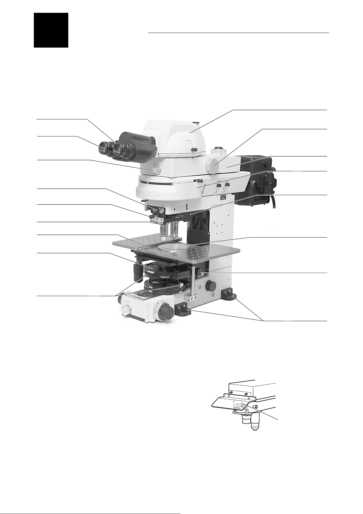
1. Main part of the microscope
Diopter adjustment
ring
Eyepiece
Optical path selector lever
Part Name
Eyepiece tube
Magnification selector dial
Variable magnification
double port attachment *
Epi-fl attachmen
Slide click release button
Objective vertical movement
lever
Sliding nosepiece lever
Rectangular stage
Condenser
Condenser centering screw
This photo depicts the ECLIPSE FN1 microscope configured with the epi-fl attachment, the variable magnification
double port attachment, and the ergonomic eyepiece tube.
* The product name for the variable magnification double port attachment is "Mag. Variable Double Port."
* The ultraviolet light shield is removed from the
microscope in the photo above. The following figure
shows the ultraviolet light shield.
Sliding nosepiece
Chambe
Condenser focus knob
Base auxiliary leg
Ultraviolet light shield
12
Page 15

Chapter 1 Part Name
A
A
r
Focus adjustment ring for the rear port
nalyzer selector lever
Lamp house
Parfocal correction
knob
Coarse focus torque adjustment ring
Rear side coarse focus knob
Rear side fine focus knob
Front side coarse focus knob
Front side fine focus knob
2
Objective
Stage movement knob
for the Y-axis
Stage movement knob
for the X-axis
Field diaphragm control
2. TE2-PS100W power supply
Brightness
control knob
Power switch
Push it to the "I" side to turn on.
Push it to the "O" side to turn off.
WARNING
The bottom of the power supply becomes extremely hot while it is in use. Do not obstruct the
air vents on the sides of the power supply.
Power indicator
This lamp is lit when power is on.
C inlet
Connect the specified power cord
that meets the voltage provided.
Refer to Chapter 7, "Specification"
for the specified power cord.
OUTPUT connector
This connector is used fo
the lamp.
It is connected to the lamp
house through the lamp
cable.
Sanwa Electric
SNS-1603-RSFb
Pin 1: Output +
Pin 2: Output Pin 3: Not used
13
Page 16
2
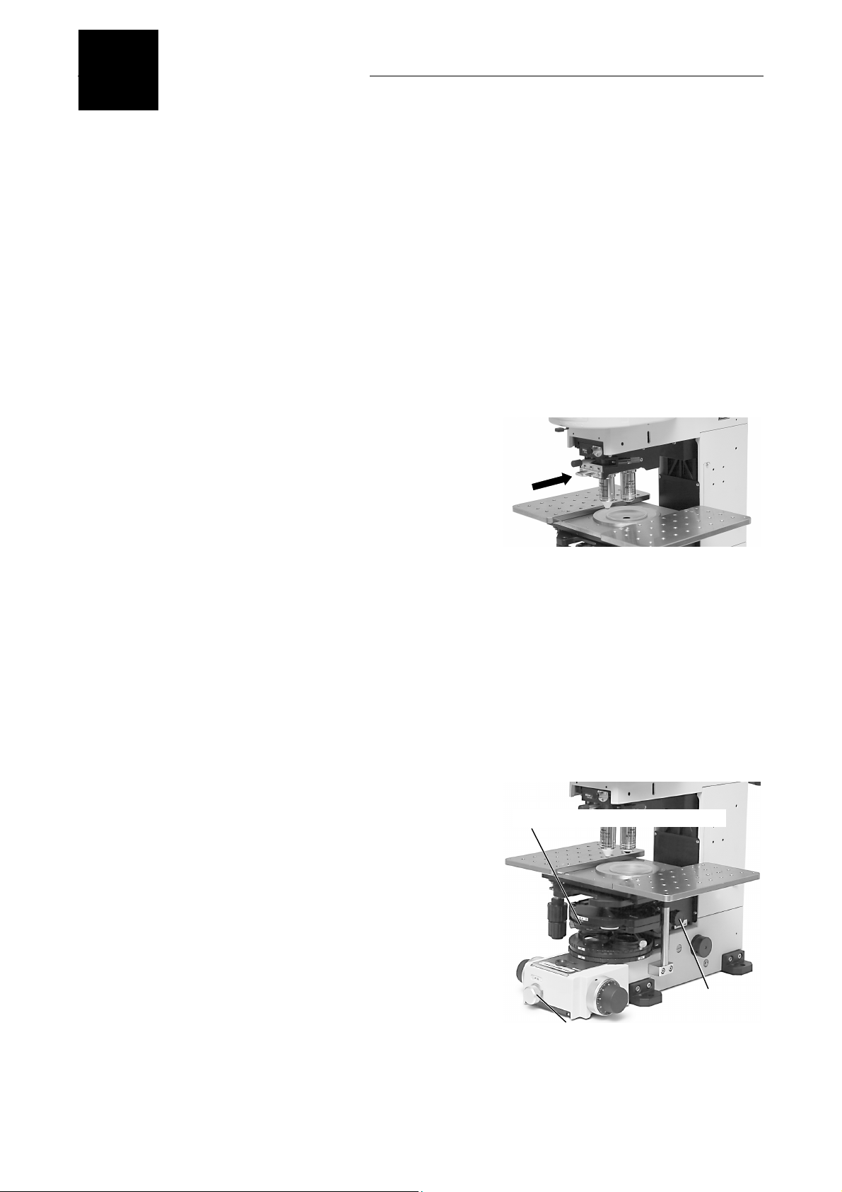
The general procedure for the microscopy with water immersion objective is described below.
For details, refer to Chapter 3, "Operation of Each Part."
Microscopy
Turn on the power supply or the optical fiber light source. (Push the switch to the "I" postion.)
1
2
3
4
Adjust the brightness with the brightness control knob on the power supply or on the optical fiber
light source.
Rotate the polarizer turret to locate the desired filter into the optical path.
Under the standard configuration, the following filters are attached to the polarizer turret.
Upper turret: NCB11
Lower turret: ND filters (ND2, ND4, and ND16)
Push in the sliding nosepiece to locate the near
side objective, the low magnification objective (4x
or 10x), into the optical path.
CAUTION:
Make sure to move the objective vertical
movement lever to the center position
when you change objectives between
the near side one and the far side one.
You cannot change objectives when the
objective vertical movement lever is
placed at the right or the left. If you
attempt to change objectives forcibly,
the microscopy may be damaged.
Push in
Refer to Section 2.2 in Chapter 3, "Selecting an
Objective."
Place the specimen on the stage.
5
6
7
8
Rotate the condenser focus knob to raise the
LWDcondenser. The LWD condenser tip must be
raised to the limit position where it does not touch
the specimen bottom.
Fully open the field diaphragm with the field
diaphragm control. And fully open the condenser
aperture diaphragm with the condenser aperture
diaphragm lever.
Move the stage to place the target part of the
specimen into the optical path.
Condenser aperture diaphragm lever
Field diaphragm
control
Condenser
focus knob
14
Page 17
Chapter 2 Microscopy
A
A
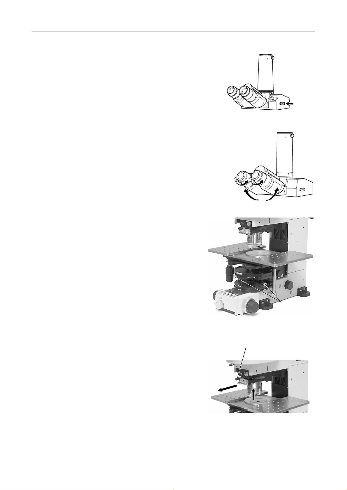
When the trinocular eyepiece tube is attached,
9
push in the optical path selector lever and select
the optical path to make 100% light go into the
binocular part.
Refer to Section 4.1 in Chapter 3, "Selecting the
10
11
Optical Path in the Eyepiece Tube (T Eyepiece
Tube, F Eyepiece Tube)."
Focus on the specimen with the coarse focus
knob and the fine focus knob.
Adjust the diopters and the interpupillary distance.
Check for your both eyes.
Push in
2
Refer to Section 4.2, "Diopter Adjustment" and
4.3, "Interpupillary Distance Adjustment" in
Chapter 3.
djust the diopters.
djust the interpupillary distance.
12
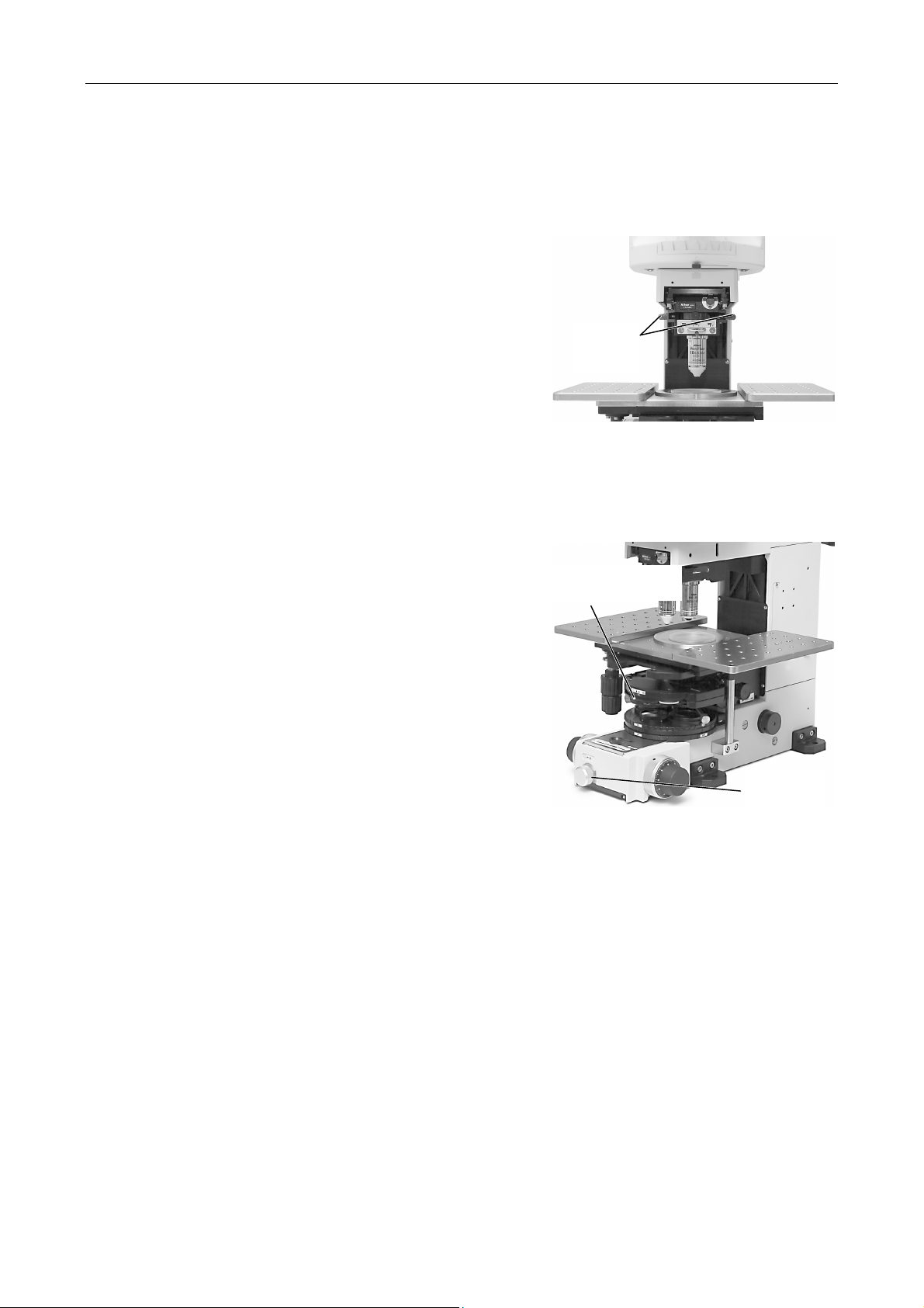
Focus and center the LWD condenser.
Refer to Section 5.1 in Chapter 3, "Focusing and
Centering the Condenser."
Condenser
centering screw
13
14
Move the objective vertical movement lever to the
center to retract the low magnification objective into
the upper position.
Pull the sliding nosepiece to the front to locate the
water immersion type objective into the optical path.
Move the objective vertical
movement lever to the center.
CAUTION:
Make sure to move the objective vertical
movement lever to the center position
when you change objectives between the
near side one and the far side one.
You cannot change objectives when the
objective vertical movement lever is placed
at the right or the left. If you attempt to
change objectives forcibly, the microscopy
may be damaged.
Pull
15
Page 18
Chapter 2 Microscopy
15
16
17
18
Move the objective vertical movement lever to the
left so that the objective tip touches the surface of
the water over the specimen.
To perform the parfocal correction, use the
parfocal correction knob on the sliding nosepiece.
With this focusing operation, a confocal position
for the two objectives can be attained.
Adjust the brightness with the brightness control
knob on the power supply or on the optical fiber
light source.
Stop down the field diaphragm with the field
diaphragm control so that it circumscribes the
viewfield.
Parfocal
correction
knobs
Condenser aperture
diaphragm lever
19
20
Refer to Section 6 in Chapter 3, "Field
Diaphragm."
Stop down the condenser aperture diaphragm
with the condenser aperture diaphragm lever to
about 70 to 80% of the numerical aperture of the
objective.
Start the microscopy.
Field
diaphragm
control
16
Page 19
Operation of Each Part
3
1
1.1
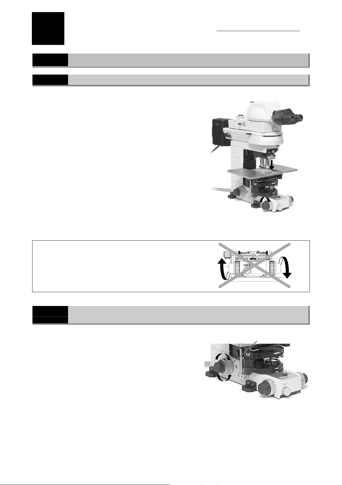
The rear side fine focus knob is marked in 1 µm
increments.
The objective rises/falls approximately 0.1 mm per one
turn of the fine focus knob.
The objective rises/falls approximately 14 mm per one turn
of the coarse focus knob.
The vertical movable range (coarse/fine focus stroke) of
the objective is 15 mm. It can be risen 13 mm above from
the focal point and can be lowered 2 mm below from the
focal point.
Never attempt either of the following actions, as they will
damage the microscope.
Coarse Focus Knob and Fine Focus Knob
Focus Knob Rotation and the Objective Vertical Movement
Focus knob rotation and the
objective vertical movement
• Rotating the left and right focus knobs in opposite directions
at the same time.
• Rotating the coarse focus knob past the stopper.
1.2
The torque of the coarse focus knob can be adjusted.
To increase the torque, rotate the torque adjustment ring
at the base of the rear side coarse focus knob in the
counterclockwise direction. To decrease the torque, rotate
the ring in the clockwise direction.
CAUTION:
Adjustment for the Rotation Torque (rotation Resistance) of the Coarse
Focus Knob
If the torque is adjusted very heavy and the
coarse focus knob is rotated, the microscope
may be damaged.
Decrease the
torque
Increase the
torque
Coarse torque adjustment ring
17
Page 20
Chapter 3 Operation of Each Part
2 Sliding Nosepiece
2
Sliding Nosepiece
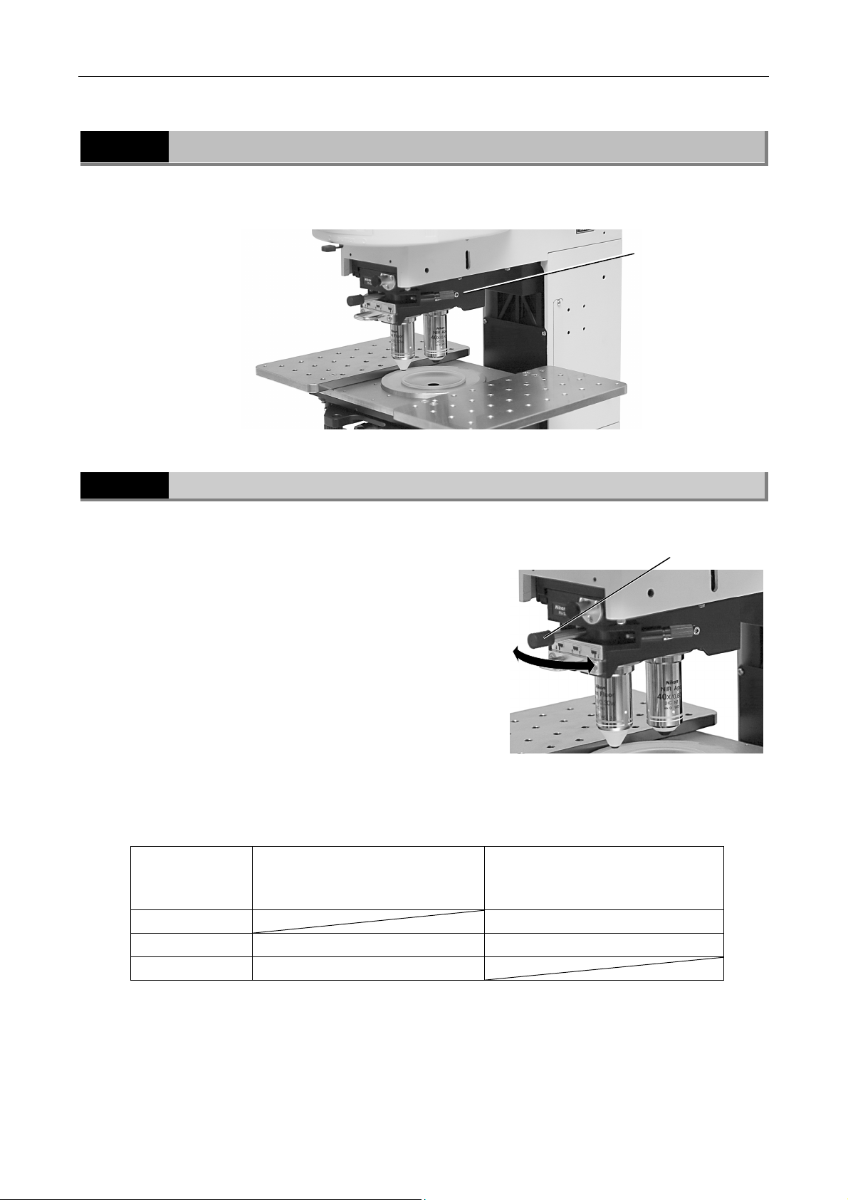
The sliding nosepiece can be attached two objectives into the near side socket and the far side socket.
The objectives are changed by sliding the nosepiece to and from.
Sliding nosepiece
2.1
You can move the objective upward and downward by
operating the objective vertical movement lever on the
sliding nosepiece from side to side. This operation is
independent of the focus knob operation.
Objective Vertical Movement Lever and the Objective Position
Objective vertical
movement lever
This operation is useful for retracting the objectives to
switch objectives and for dipping the objective into the
water to perform the water immersion.
You can operate the lever only when the objective is
placed in the optical path.
The vertical movable range of the objective is up to 15 mm
above the focal point. With this movable range, you can
observe a specimen in a high petri dish.
The table below shows the relationship between the objective vertical movement lever position and the
objective position.
Lever position
Right Observation position
Center Retracted position Retracted position
Left Observation position
Near side objective position
(The near side objective is located
in the optical path.)
Far side objective position
(The far side objective is located in
the optical path.)
18
Page 21
Chapter 3 Operation of Each Part
Y
2 Sliding Nosepiece
2.2
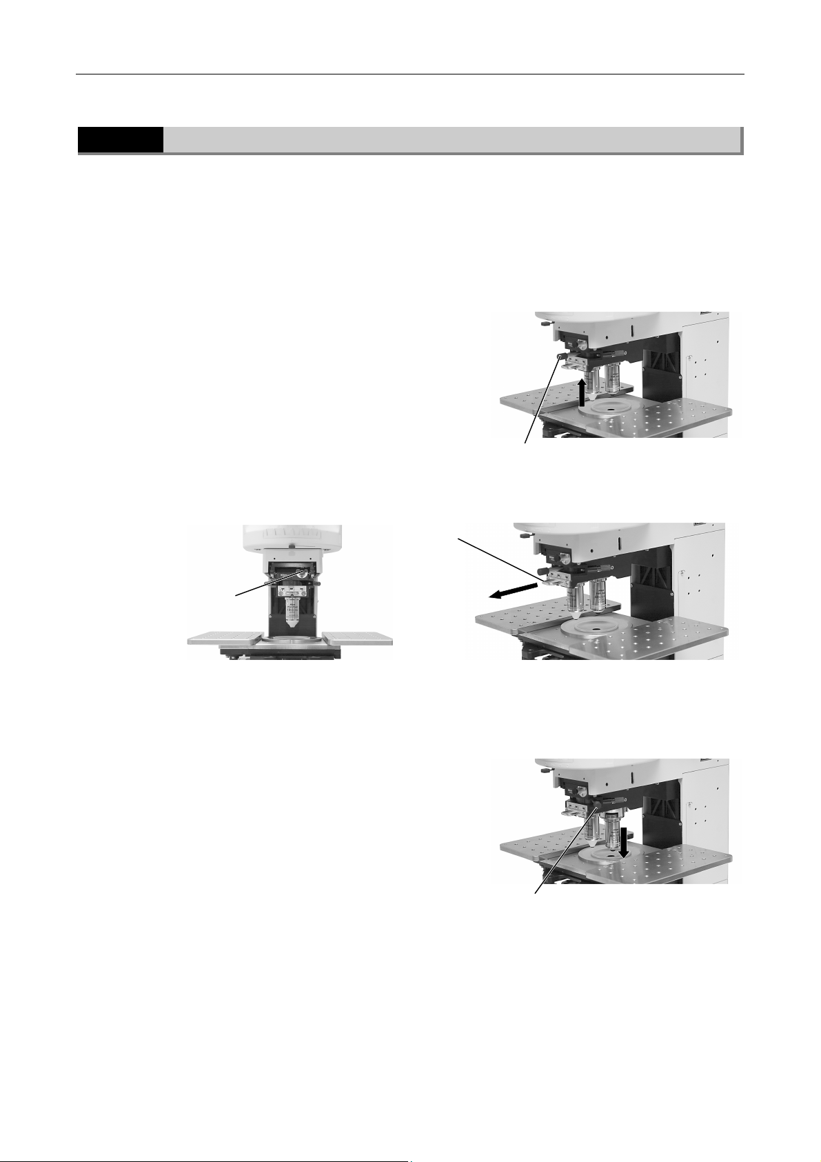
In this section, an example case is explained. (Changing objectives from the near side to the far side)
CAUTION:
1
2
Switching Objectives
ou cannot change objectives when the objective vertical movement lever is placed at the right
or the left. If you attempt to change objectives forcibly, the microscopy may be damaged.
Make sure to move the objective vertical movement lever to the center position when you
change objectives between the near side one and the far side one.
Move the objective vertical movement lever from
the left to the center. The near side objective is
retracted.
With the near side objective retracted, push the slide click release button and pull the sliding
nosepiece lever fully to the near side.
Sliding nosepiece lever
Move the lever to the center.
3
Slide click
release button
Release the slide click release button. Move the sliding nosepiece slightly to and from to find a
3
click-stop position and fit in it.
Gently move the objective vertical movement
4
lever from the center to the right. The far side
objective will be placed in the observation
position.
Pull
Move the lever to the right.
19
Page 22
Chapter 3 Operation of Each Part
2 Sliding Nosepiece
2.3
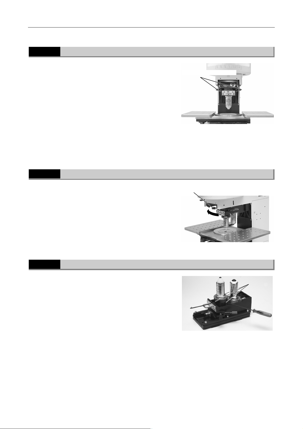
Parfocal Adjustment for the Objectives
Usually, the focal length for a dry type objective is different
from that of a liquid immersion type objective. If you
change objectives between these types with no correction,
the image will go out of focus. In this case, adjust the
parfocal correction knobs on the sides of the sliding
nosepiece.
To perform the parfocal correction adjustment, move the
objective vertical movement lever to the left or the right.
The parfocal correction knob on the left side is used for the
near side objective, and the parfocal correction knob on
the right side is used for the far side objective.
Turn the knob in a clockwise direction to raise the
objective (to raise the focal position).
2.4
Push the objective vertical movement lever on the
nosepiece farther than the normal position at the left or the
right. The objective moves down 1 mm. When the lever is
released, the lever and the objective come back to their
original positions.
Dipping Function for a Water Immersion Type Objective
Parfocal correction knob
Near side
objective
Push the lever as far as it will go.
Far side
objective
CAUTION:
To prevent damage to the specimen and the
objective, be careful not to perform the dipping
function accidentally.
2.5
Centering the Objective
When you wish to decrease the difference between the
two center positions of the near side objective and the far
side objective, center the objectives.
Rotate the three M3 hexagonal socket head set-screws.
Adjust the center positions of the near side objective and
the far side objective so that they come together. To adjust
the center positions more accurately, use an eyepiece with
crosshairs.
When you wish to perform a microscopy of a small
specimen such as a patch clamp method, you should
center the objectives beforehand.
Centering screws
20
Page 23
Chapter 3 Operation of Each Part
3 Single Objective Holder
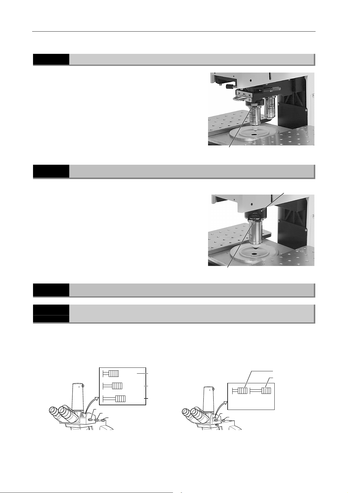
2.6
To attach/detach the DIC slider for the DIC microscopy,
lower the objective.
The DIC sliders are inserted into the DIC slider slots on
the front right side of the both objectives.
Attaching/Detaching the DIC Slider
3
Single Objective Holder
The single objective holder is used only for the LWD 16x
water immersion type objective.
The DIC slider for the DIC microscopy is inserted into the
DIC slider slot on the upper side of the objective clamp
screw.
DIC slider
Single objective holder
3
DIC slider
4
4.1
Eyepiece Tube
Selecting the Optical Path in the Eyepiece Tube (T Eyepiece Tube, F Eyepiece
Tube)
The optical path selector lever can be used to select the way to distribute light to the binocular part
and the vertical tube.
Lever position
T eyepiece tube F eyepiece tube
Distribution of light
Binocular part:
vertical tube
BINO
BINO
&
PHOTO
PHOTO
1
2
3
1
2
3
100:0
20:80
0:100
Lever position
BINO
1
2
PHOTO
Distribution of light
Binocular part:
vertical tube
1
100:0
0:100
2
21
Page 24
Chapter 3 Operation of Each Part
A
4 Eyepiece Tube
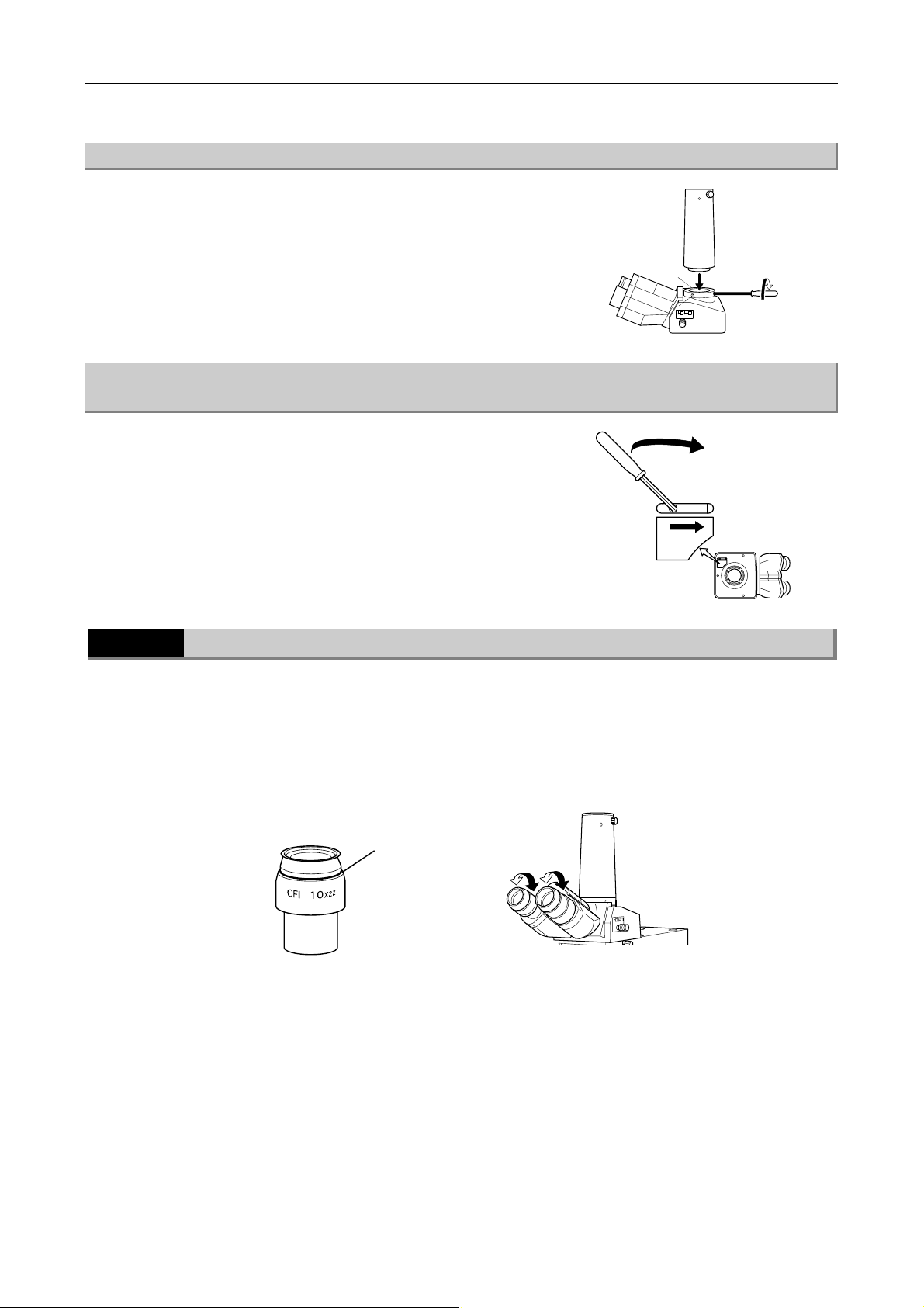
(1) Vertical tube adapter
A photo adapter is attached as a standard accessory for
photomicrographic equipment. To use this adapter, insert it
into the vertical tube of the eyepiece tube and fix it with
three screws on the vertical tube.
If you wish to use a TV camera, you must attach an
optional TV adapter into the vertical tube.
(2) Disabling the Clicking of the Optical Path Selector Lever on the T Eyepiece Tube
and the F Eyepiece Tube
There is a "NO CLICK" switch on the eyepiece tube mount
part. When this switch is slid in the direction of the arrow,
the clicking of the optical path selector lever is disabled.
So, if you need to eliminate slight vibrations resulting from
the clicking action, slide this switch with a narrow piece of
metal such as the hexagonal screwdriver provided.
NO CLICK
4.2
Diopter Adjustment
Diopter adjustment compensates for differences in visual acuity between the right and left eyes,
improving binocular observation. It's hard to adjust the diopters with the standard procedure because
of the sliding nosepiece. So, adjust the diopters as described below.
Turn the diopter adjustment rings on both eyepieces to align their engraved lines with the
1
edges of the outer tubes of the eyepieces. (They are the standard positions for the diopter
rings.)
Engraved line
Diopter adjustment standard position
Place the low magnification objective into the optical path. Observe the specimen with both
2
eyes and focus on the specimen surface by using the focus knob.
Observe the specimen with your right eye only and focus on the specimen surface by using
3
the diopter adjustment ring.
Do the same for your left eye.
* When an eyepiece with a reticle for photomicrography is used, adjust the diopters as described below.
1
djust the diopter adjustment ring to the standard position. And place the low magnification
objective into the optical path.
22
Page 25
Chapter 3 Operation of Each Part
5 LWD Condenser
Observe the specimen with both eyes and focus on the specimen surface by using the focus knob.
2
Rotate the right diopter adjustment ring while observing the specimen with your right eye so
3
that the reticle and the specimen come into focus.
Do the same for your left eye.
4.3
Before adjusting the interpupillary distance, focus on the specimen with a low magnification objective
by following the steps of 1 to 10 in Section 2 of Chapter 1, "Microscopy."
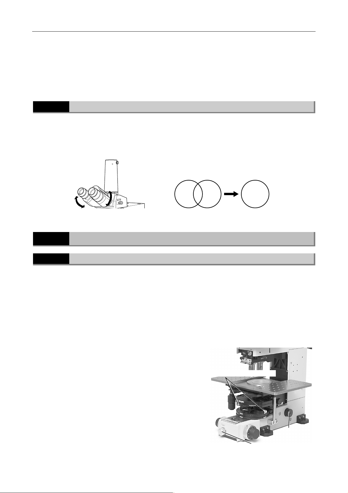
Adjust the interpupillary distance so that the viewfields for both eyes come together. Doing so will
make observation through the binocular eyepieces with both eyes easier.
Interpupillary Distance Adjustment
3
Converge until the right and left view fields coincide.
5
5.1
The LWD condenser must be focused and centered so that the light passing through the LWD
condenser forms an image at the correct location (the center of the optical path) on the specimen
surface.
Before focusing and centering the LWD condenser, focus on the specimen with a low magnification
objective by following the steps of 1 to 11 in Section 2 of Chapter 1, "Microscopy."
When you wish to use the 4x objective with the LWD condenser, attach the additional lens for 4x
magnification into the turret of the LWD condenser and place it into the optical path. When you wish to
use an objective of a magnification higher than the 4x magnification, you need not attach the additional
lens.
1
2
3
LWD Condenser
Focusing and Centering the LWD Condenser
Rotate the field diaphragm control to fully stop
down the diaphragm.
Turn the condenser focus knob to form the field
diaphragm image on the specimen image.
Turn the condenser centering screws so that the
field diaphragm image is roughly positioned in the
center of the view field.
Condenser centering screws
Field diaphragm control
Condenser focus
knob
23
Page 26
Chapter 3 Operation of Each Part
5 LWD Condenser
Place an objective of 40x or 80x into the optical
4
path. Rotate the parfocal correction knob on the
sliding nosepiece to focus on the specimen.
Parfocal
correction
knobs
Near side
objective
Far side
objective
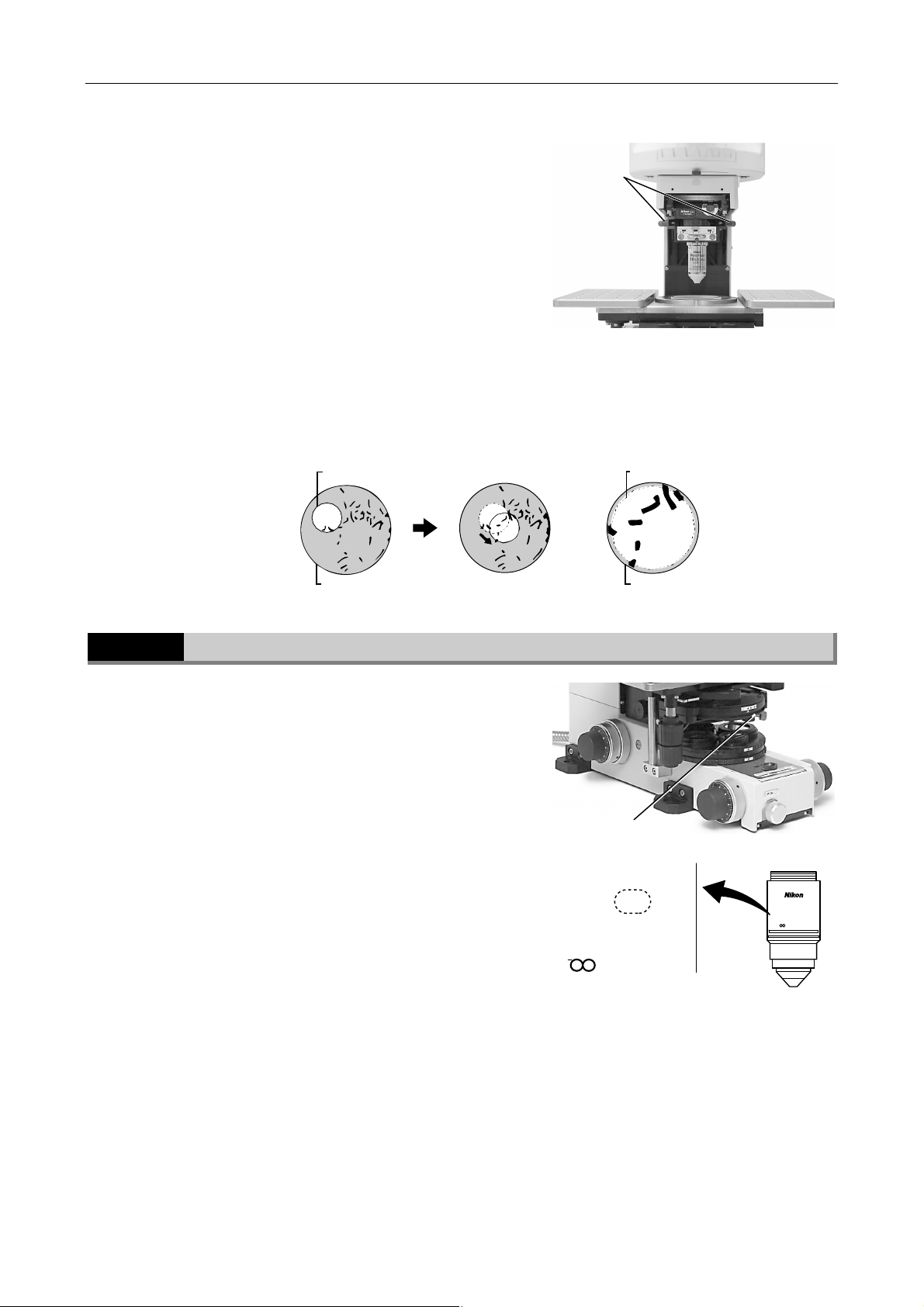
Turn the condenser focus knob to form the field diaphragm image on the specimen surface.
5
Turn the condenser centering screws so that the field diaphragm image is positioned in the
6
center of the view field. This is easiest if you set the field diaphragm aperture to slightly
smaller than the eyepiece view field.
Field diaphragm image
Eyepiece viewfield
5.2
Adjusting the Condenser Aperture Diaphragm
The aperture diaphragm is important because it is related
to the resolution, contrast, depth of focus, and brightness
of the optical image. Turning the condenser aperture
diaphragm lever on the LWD condenser changes the size
of the aperture diaphragm.
As the aperture diaphragm is stopped down, resolution
and brightness are reduced while contrast and depth of
focus are increased. Conversely, as the aperture
diaphragm is opened, resolution and brightness are
increased while contrast and depth of focus are reduced. It
is not possible to adjust one pair of characteristics without
affecting the other.
Generally, a satisfactory image with appropriate contrast
can be obtained with an aperture setting that is 70% to
80% of the numerical aperture of the objective. The
numerical aperture is indicated on the barrel of each
objective.
Example: when the numerical aperture of an objective is
0.80,
0.8 x 0.7 to 0.8 = 0.56 to 0.64
If the aperture diaphragm is stopped down too far, the
resolution is reduced; therefore, except when viewing a
nearly transparent specimen, we do not recommend
stopping down the aperture to less than 60% of the
numerical aperture of the objective.
Field diaphragm image
Eyepiece viewfield
Condenser aperture
diaphragm lever
Fluor
40
x / 0.80 W
DIC M
40
Fluor
X/0.80W
DIC M
/0 WD 2.0
/0 WD 2.0
"40x/ 0.80" means that the
magnification is x40 and the
numerical aperture is 0.80.
24
Page 27
Chapter 3 Operation of Each Part
A
A
5 LWD Condenser
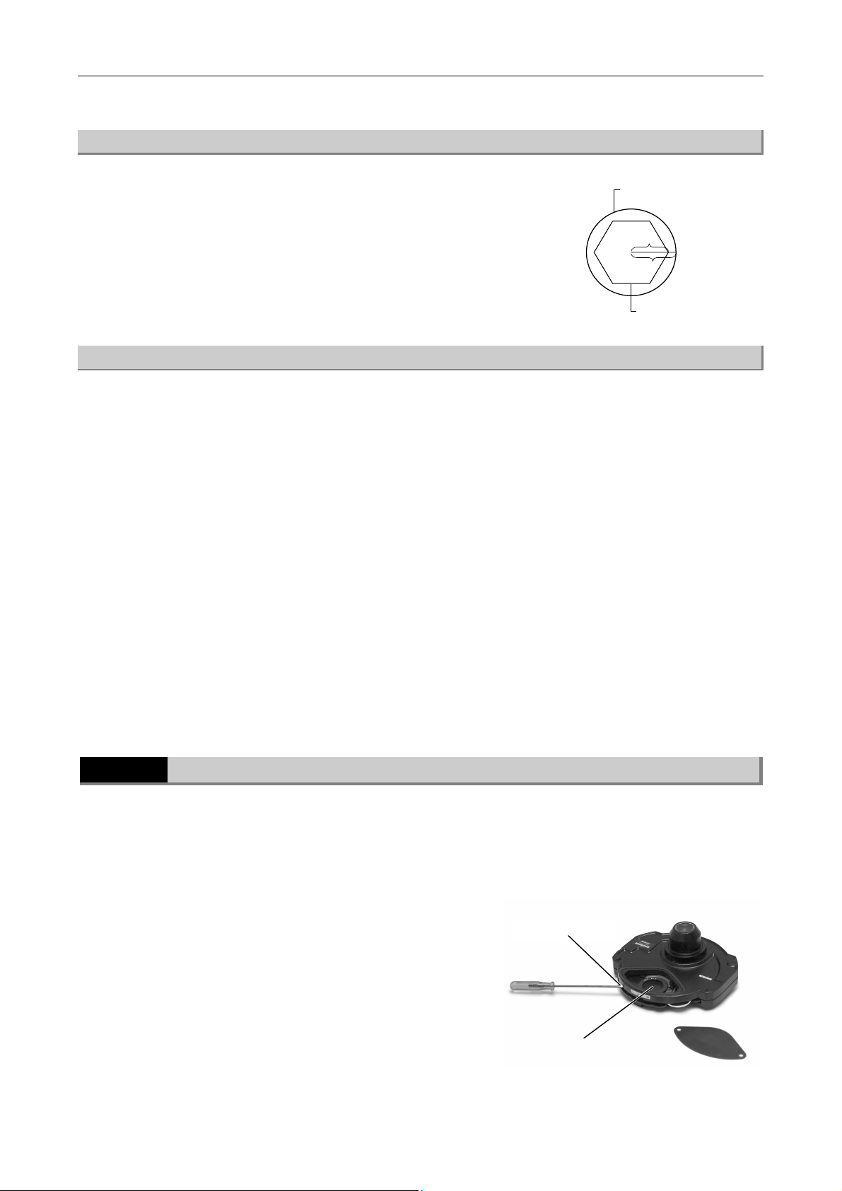
(1) Aperture diaphragm adjustment with the pupil of the objective
Remove one of the eyepieces and look into the sleeve.
You can see the pupil of the objective (that is a bright area
when the aperture diaphragm is fully opened.) Stop down
the condenser aperture diaphragm so that the diaphragm
aperture is adjusted to about 70% to 80% of the pupil of
the objective.
(2) Aperture diaphragm adjustment with an optional centering telescope
Observe an enlarged view of the pupil of the objective with an optional centering telescope and adjust the
aperture diaphragm of the LWD condenser.
1
Remove one of the eyepieces. And then, attach an optional centering telescope with an
optional adapter in place.
Fully stop down the aperture diaphragm with the condenser aperture diaphragm lever.
Pupil of the objective
70~ 80
100
perture diaphragm
2
3
4
5
Turn the eyepiece section of the centering telescope with holding the flange of the centering
telescope to focus on the aperture diaphragm image.
Turn the diaphragm control lever to adjust the aperture diaphragm. (This is normally adjusted
to 70-80% of the pupil of the objective.)
Remove the centering telescope with the adapter and attach the eyepiece to its original
position.
3
5.3
You can perform the bright-field microscopy under the diascopic illumination (with 4x objective to 100x
objective), the differential interference contrast microscopy under the diascopic illumination (with
visible lights or with infra-red lights), and the microscopy under the diagonal illumination when you use
the LWD condenser. And you can attach an optical element into the condenser turret of the LWD
condenser for each microscopy.
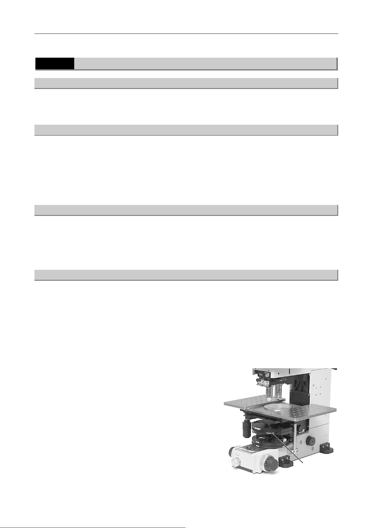
1
Attaching an Optical Element into the LWD Condenser Turret
Remove the two button bolts on the condenser turret
of the LWD condenser and remove the cover.
Attach a desired optical element in place and fix it.
Fix the element.
2
Put the cover back to its original position. Fix the
3
cover with the button bolts.
25
ttach an optical element.
Page 28
Chapter 3 Operation of Each Part
5 LWD Condenser
5.4
Operation of the LWD Condenser for Each Microscopy
(1) For the bright-field microscopy
Place the vacant hole of the turret into the optical path.
(2) For the bright-field microscopy with the 4x objective
Attach the additional lens for 4x magnification into the DIC prism N2 position of the condenser turret of
the LWD condenser and fix it with a set-screw. And then, place it into the optical path. (* There is no
indication about the 4x magnification on the condenser turret.)
When you wish to use an objective with a larger magnification than the 4x objective, you need not
attach the additional lens.
(3) For the DIC microscopy
Attach an objective for the DIC microscopy.
Attach a DIC prism into the condenser turret of the LWD condenser that meets the specification of the
objective. You can see the DIC prism type on the side of the objective.
(4) For the microscopy under the diagonal illumination
You can observe a nearly transparent specimen by improving the contrast under the diagonal
illumination. And, you can rotate the slit for the diagonal illumination around the optical center to
change the orientation of the shade of the specimen.
Attach a slit for the diagonal illumination into the condenser turret of the LWD condenser.
1
Rotate the turret and place the slit into the optical path.
2
3
Rotate the slit orientation ring on the turret to
adjust the illumination light orientation.
Slit orientation
ring
26
Page 29
Chapter 3 Operation of Each Part
6 Field Diaphragm
6
Field Diaphragm
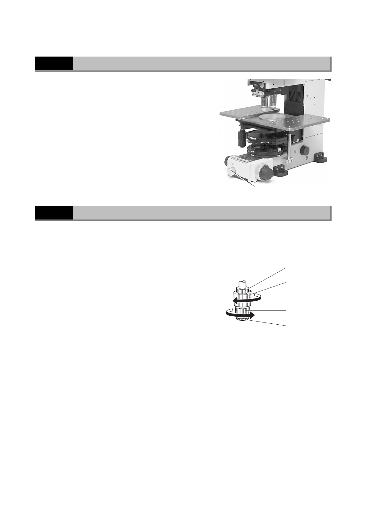
The field diaphragm restricts the illumination light to the
area on the specimen to be observed. Operating the field
diaphragm ring changes the size of the field diaphragm.
For normal observation, the size of the diaphragm should
be such that it is just outside the edge of the viewfield.
If a broader area than necessary is illuminated, stray light
will enter the optical system, creating flaring, reducing the
contrast of the optical image. The operation of the field
diaphragm is especially important in photomicrography;
generally, the best results are obtained by stopping down
the field diaphragm to just slightly larger than the image
area or the area that will be reproduced on the film, that is,
the size of the picture composition frame (for a digital
camera, the size of the CCD).
Field diaphragm control
7
Stage
You can adjust the rotation torques (rotation resistances) of the stage movement knobs for the X-axis
and for the Y-axis. To adjust them, move the stage to the edge of the movement. It makes the
adjustment easy.
3
Torque adjustment for the Y-axis
To increase the torque, rotate the knob B in the arrow a
direction while holding the knob A. To decrease the torque,
rotate the knob B in the opposite direction while holding
the knob A.
Torque adjustment for the X-axis
To increase the torque, rotate the knob C in the arrow b
direction while holding the knob D. To decrease the
torque, rotate the knob C in the opposite direction while
holding the knob D. When you hold the knob D, put your
finger on the lower hole of the knob D.
Increase the
torque
a
Decrease the
torque
Decrease the
torque
Increase
b
the torque
Knob A
Knob B (Y-axis)
Knob C (X-axis)
Knob D
27
Page 30

Chapter 3 Operation of Each Part
8 Water Immersion Operation (Water Immersion Type Objective Handling)
8
Water Immersion Operation (Water Immersion Type
Objective Handling)
An objective with a "W" mark is a water immersion type objective. It is designed to focus on a specimen at
a working distance in water. To use this type of objective, apply water (normal saline solution or such) into
a chamber. And lower the objective to make its tip touch the water.
When you wish to observe a specimen to a depth of 0.2 mm or so on from the surface, for example a
sliced brain, you are recommended to perform an observation under infrared rays or to use a water
immersion type objective with a correction ring, Plan 100xW.
CAUTION:
Leaking water from the chamber can give rise to corrosion of the stage or the condenser lens.
If water in the chamber spills on the stage or on the condenser lens, it should be wiped out
soon.
After use, wipe off water from the tip of the objective, then follow up by wiping with absolute alcohol.
If you observe water stains, apply a small amount of neutral detergent and wipe gently, then follow up with
absolute alcohol.
9
Cleaning the Oil Immersion Type Objective After Use
To wipe off immersion oil, use petroleum benzine. For optimum results, we recommend following up
petroleum benzine with absolute alcohol (ethyl or methyl alcohol).
If petroleum benzine is unavailable, use methyl alcohol. However, methyl alcohol does not clean as
well as petroleum benzine, it will be necessary to wipe the surface repeatedly. (Usually, three- or
four-times wipe is sufficient to clean the lenses.)
WARNING:
When using petroleum benzine or absolute alcohol, always follow the instructions
provided by the manufacturer. These liquids are highly flammable and must be kept
away from flames and sparks.
28
Page 31
Chapter 3 Operation of Each Part
10 Variable Magnification Double Port Attachment
10
Variable Magnification Double Port Attachment
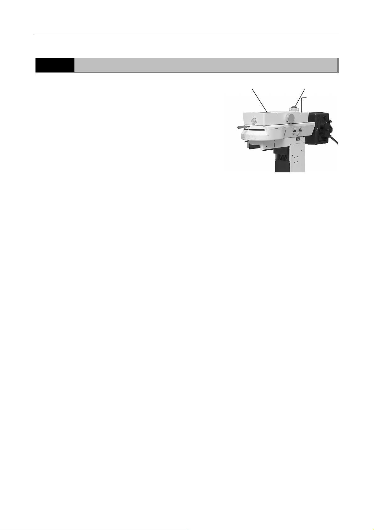
You can attach an eyepiece tube onto the front port of the
variable magnification double port attachment and a 2/3
inch TV camera onto the rear port of the variable
magnification double port attachment.
You can select the port condition between the
simultaneous usage of both ports and the front port usage
only.
When the simultaneous usage of both ports is selected,
100% of visible lights goes through the front port and
100% of infrared rays goes through the rear port.
The magnification for the rear port can be selected from
among x0.35, x2, and x4.
With the rear port, the water immersion type objective of
x16 and the numerical aperture 0.80 enables various
observations from a low magnification with wide view field
to a high magnification with high resolution without
changing objectives.
Take note of that vignettings may occur when the
magnification for the rear port is x0.35. This is not a
malfunction.
Front port
Rear port
3
The front port can be used for the following observations:
• Bright-field microscopy
• Microscopy under the diagonal illumination
• DIC microscopy (combined with the FN-IR/ISA DIC IR
analyzer or the D-FL U-EPI FL epi-fl attachment)
• Fluorescent microscopy (combined with the J-FL epi-fl
attachment)
The rear port can be used for the following observations:
• Infrared bright-field microscopy
• Infrared microscopy under the diagonal illumination
• Infrared DIC microscopy (for DIC observations under
infrared rays)
CAUTION:
When the J-FL epi-fl attachment and the variable
magnification double port attachment are used
together, the indications for the filter cassette
type and the turret number on the J-FL epi-fl
attachment are hidden.
29
Page 32
Chapter 3 Operation of Each Part
10 Variable Magnification Double Port Attachment
10.1
Port Selection
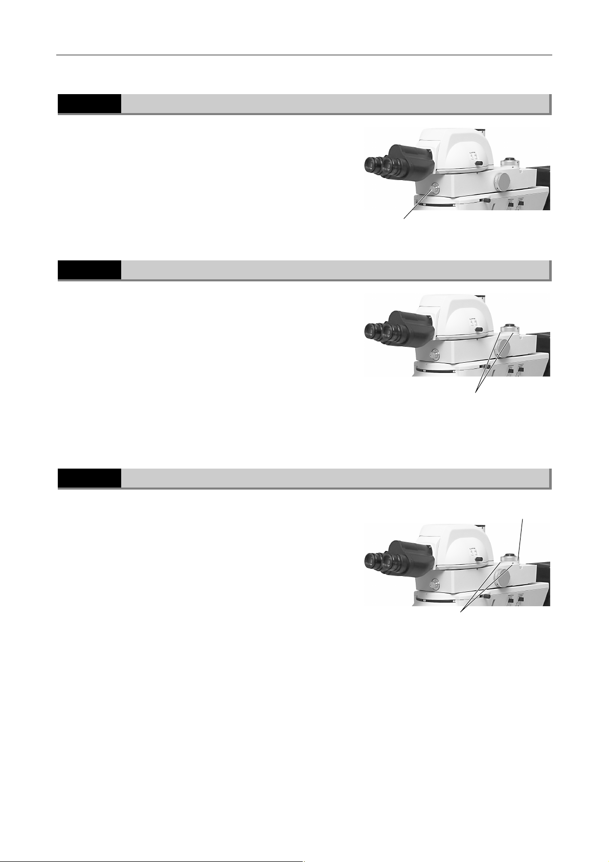
To use the front port and the rear port simultaneously,
Rotate the port selector knob 180 degree in a
counterclockwise direction.
To use the front port only,
Rotate the port selector knob 180 degree in a clockwise
direction.
10.2
Mounting Parts of the Ports
The front port is a dovetail joint of 46 mm in diameter. This
port is used for an eyepiece tube or a variable
magnification turret. *
The rear port is a C mount unit. This port is used for a TV
camera. When the two M4 set screws at the C mount unit
screw part are loosened, the C mount unit can be
removed. When the C mount unit is removed, the rear port
can be used as an ISO mount of 38 mm in its inner
diameter and of 29 mm distance from the hardware edge
to the imaging position.The product name for the variable
magnification turret is "Mag. Variable Turret."
Port selector knob
M4 set screws at the C mount unit
screw part
10.3
Mounting a 2/3 Inch TV Camera
When the M4 set screw on the knurled ring of the rear port
is tighten and the two M4 set screws at the C mount unit
screw part are loosen, the C mount unit can be rotated
freely. A 2/3 inch TV camera can be mounted onto the rear
port in this condition.
After mounting the TV camera, loosen the M4 set screw on
the knurled ring and tighten the M4 set screw at the C
mount unit screw part.
M4 set screw on the knurled ring
M4 set screws at the C mount unit screw part
30
Page 33
Chapter 3 Operation of Each Part
10 Variable Magnification Double Port Attachment
10.4
Aligning the Optical Paths for the Front Port and the Rear Port
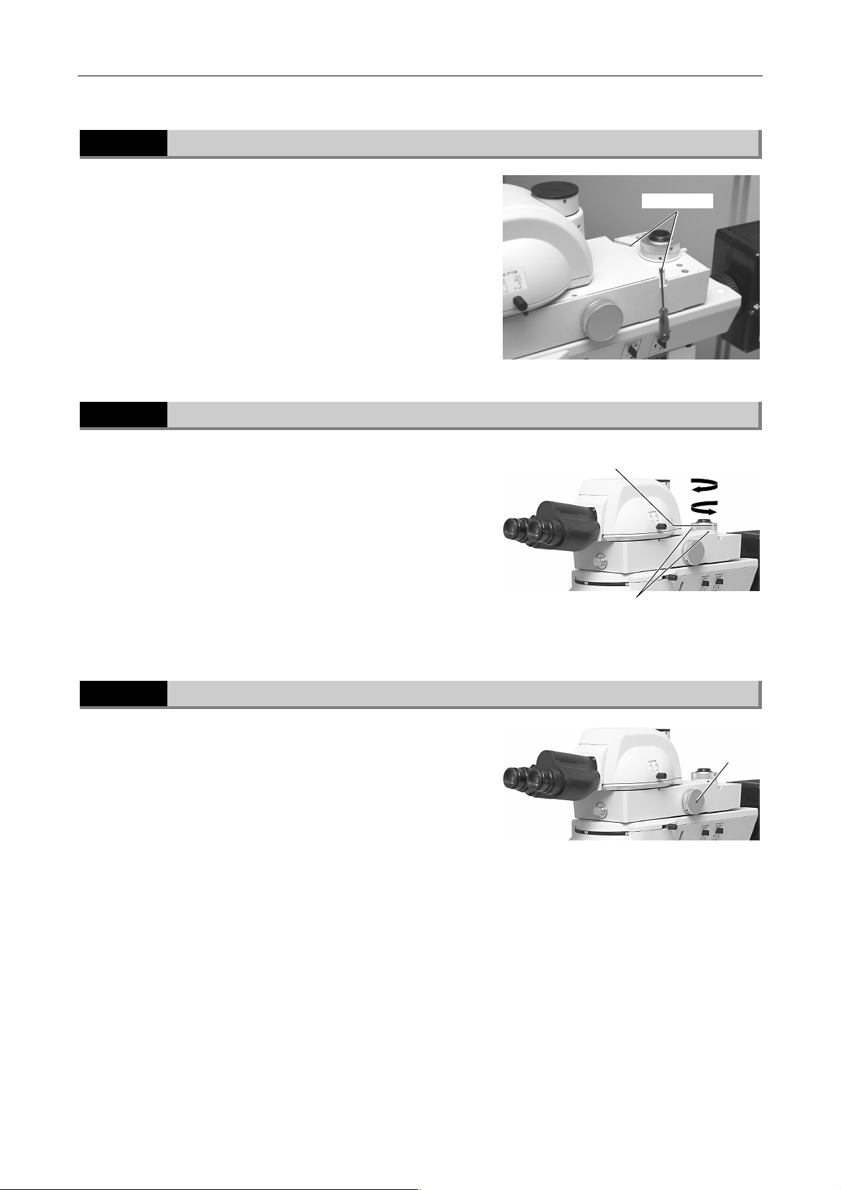
To align the optical paths for the front port and the rear
port, adjust the rear port position.
Rotate the two M4 set screws to adjust the rear port
position (for the 2/3 inch TV camera).
After the adjustment, tighten the M4 set screw on the back
of the tube.
10.5
Parfocal Adjustment for the Front Port and the Rear Port
You can adjust the focus position for the rear port so that
the focus positions for the front port and the rear port
come together.
Check that the M4 set screw on the knurled ring on the
rear port is loosened and that the M4 set screws at the C
mount unit screw part is tightened.
Set screws
M4 set screw on the knurled ring
B
3
A
To raise the camera position on the rear port, rotate the
knurled ring in the "A" direction. To lower the camera
position, rotate the knurled ring in the "B" direction. During
the adjustment, watch the monitor image.
10.6
Selecting the Magnification for the Rear Port
You can change the magnification of the rear port by
rotating the magnification selector dial on the right side of
the tube in the sequence of 0.35x, 2x, and 4x.
You cannot change the magnifications between 0.35x and
4x directly.
M4 set screws at the C mount unit
screw part
Magnification
selector dial
31
Page 34
Chapter 3 Operation of Each Part
11 Polarizer Turret
10.7
For the DIC Microscopy
(1) To perform the infrared DIC microscopy through the rear port
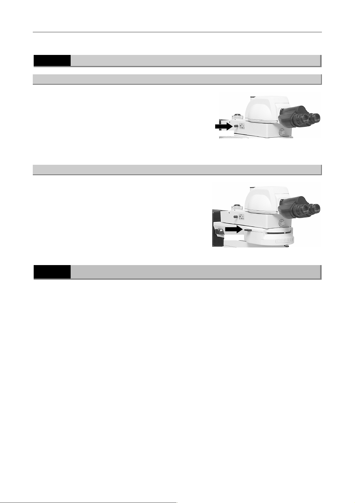
Push in the lever on the left side of the variable
magnification double port attachment to locate the IR
analyzer into the optical path.
When you wish to use the epi-fl attachment together,
locate the empty hole into the optical path for the epi-fl
attachment turret and check that the analyzer in the epi-fl
attachment turret is not used..
Push in
(2) To perform the infrared DIC microscopy through the rear port
You must use the simple analyzer, FN-IR/ISA DIC IR
analyzer, or the epi-fl attachment, D-FL U-EPI FL, to
perform the DIC microscopy through the front port.
When you use the epi-fl attachment, insert the DIC
analyzer.
Push in
11
Polarizer Turret
You can perform the DIC microscopy under visible lights (the wavelength range is from 430 nm to 770
nm) and under infrared rays (the wavelength range is 850 nm to 950 nm) with the microscope FN1.
To perform the DIC microscopy, attach a polarizer for visible lights or infrared rays (the FN-P polarizer
or the FN-IRP polarizer) into the upper turret of the polarizer turret.
32
Page 35
Chapter 3 Operation of Each Part
11 Polarizer Turret
11.1
Attaching Filters
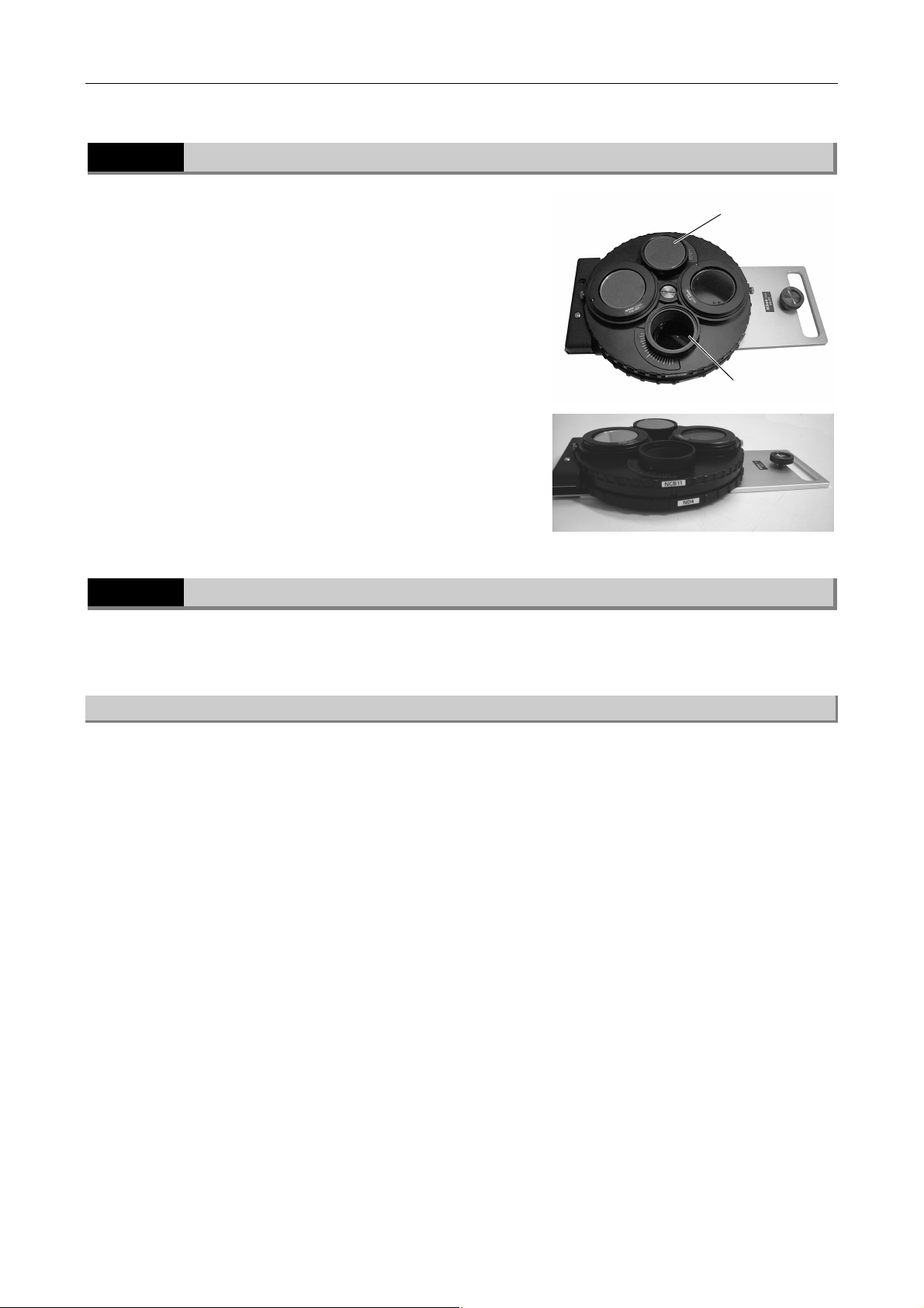
The polarizer turret consists of the upper turret and the
lower turret.
In the standard configuration, three types of ND filters are
attached (ND2, ND4, and ND16) in the lower turret. One
position of the turret is an empty hole position.
An optional filter of 33 mm diameter can be attached into
the empty hole position of the upper turret. In the standard
configuration, an NCB filter is attached.
11.2
For the DIC microscopy
In this section, an example case is explained. (The DIC microscopy under the infrared rays is
described.)
NCB filter
3
Empty hole
position
(1) Preparations
When the variable magnification double port attachment is used,
Locate the analyzer into the optical path of the rear port.
Remove the DIC prism of the single objective holder from the optical path. And remove the DIC prism
of the condenser lens from the optical path.
When the variable magnification double port attachment and the epi-fl attachment (D-FL UEPI
FL) are used,
Locate the empty hole into the optical path for the epi-fl attachment turret and check that the analyzer
in the epi-fl attachment turret is not used.
Remove the DIC prism of the single objective holder from the optical path. And remove the DIC prism
of the condenser lens from the optical path.
When the trinocular eyepiece tube and the analyzer (FN-IR/ISA DIC IR analyzer) are used or
when the epi-fl attachment (D-FL U-EPI FL) is used,
Locate the IR analyzer into the optical path.
Remove the DIC prism of the sliding nosepiece from the optical path. And remove the DIC prism of the
condenser lens from the optical path.
33
Page 36
Chapter 3 Operation of Each Part
A
A
11 Polarizer Turret
(2) Attaching the IR Polarizer
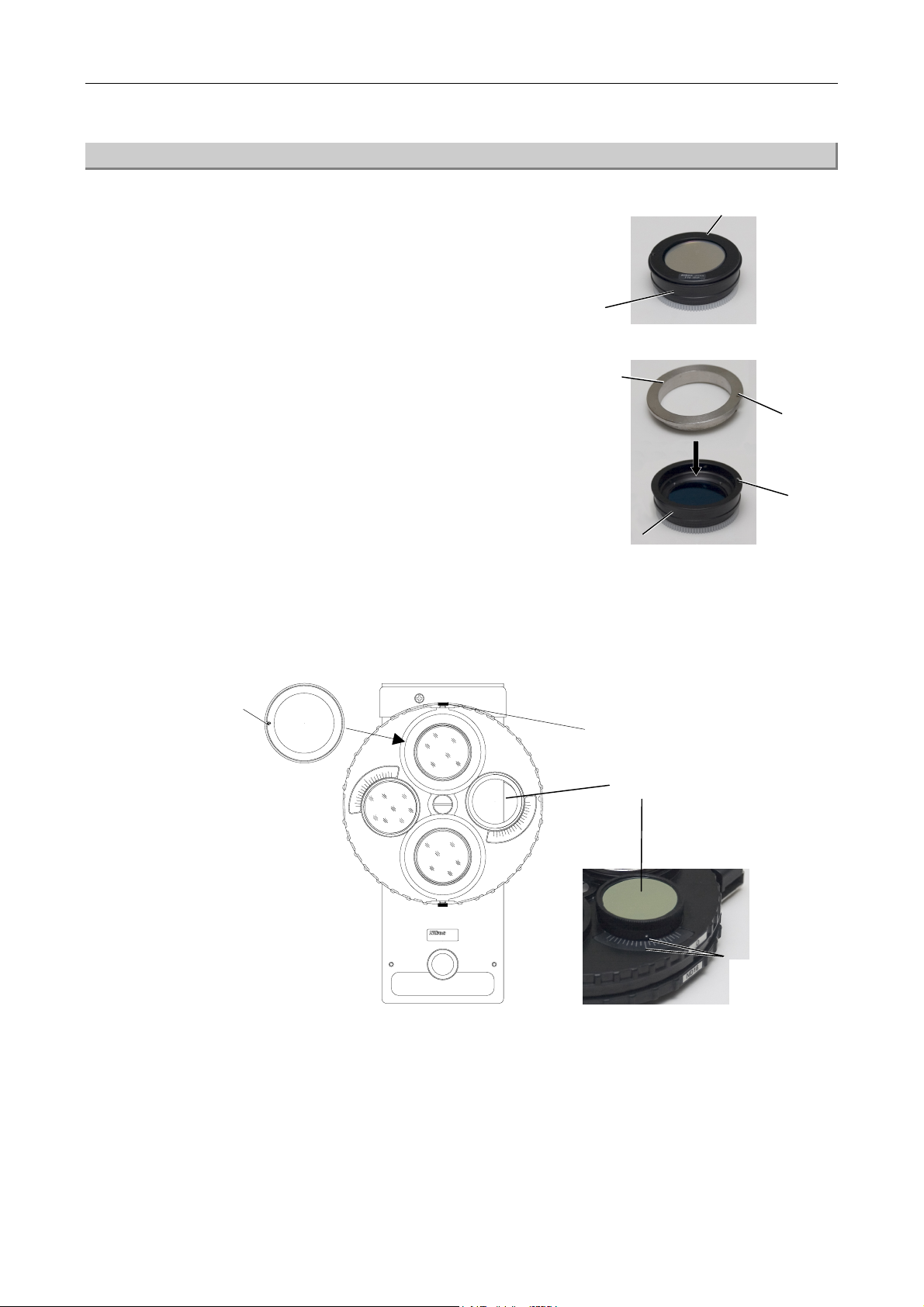
Separate the upper part (band pass filter and 1/4
1
lambda plate) and the lower part of the IR
polarizer.
Upper part
(Band pass filter and 1/4 lambda plate)
2
3
Lower part
Insert the adjustment tool for the 1/4 lambda plate
orientation, which is provided with the polarizer
turret, into the lower part of the IR polarizer.
In doing so, adjust the notch position on the
adjustment tool for the 1/4 lambda plate and the
protrusion position on the lower part of the IR
polarizer.
Rotate the knurled ring on the right side of the polarizer turret to adjust the index (a white
point) to the center line of the scale. Insert the IR polarizer assembled in Step 2 into the upper
turret of the polarizer turret. The notch of the IR polarizer must be oriented in the way as
shown in the figure.
Notch
djustment
tool for the 1/4
lambda plate
orientation
Lower part of the IR polarizer
Clamp screw
Notch
Protrusion
4
5
Knurled ring
JAPAN
FN-PT
lign the white
point and the
Attach the polarizer turret into the microscope body.
Rotate the knurled ring on the right side of the polarizer turret and search the position where
the view becomes darkest. After the adjustment, tighten the clamp screw.
center line.
34
Page 37

Chapter 3 Operation of Each Part
11 Polarizer Turret
Remove the 1/4 lambda plate and insert the upper part of the IR polarizer (the band pass filter
6
11.3
1
2
and the 1/4 lambda plate).
Contrast Adjustment
Insert the DIC slider into the single objective holder or into the sliding nosepiece to locate the
DIC prism of the condenser into the optical path.
Rotate the knurled ring on the right side of the polarizer turret upper side to change the
polarizer orientation and adjust the contrast.
3
35
Page 38

4
Assembly
WARNING
To prevent electrical shock or fire, turn off the power switch of the power supply
(flip the switch to the "O" side) during assembly. The electrical power should be
supplied after assembling the microscope system.
CAUTION
• When assembling the microscope, assemble the eyepiece tube first.
• To carry the microscope, first detach the lamp house. Tilt the microscope
body while supporting it and then securely hold it by the base.
• Never grasp the focus knobs, the eyepiece tube, the sliding nosepiece, the
stage, or so on when carrying the microscope system. This may cause the
part to come off, resulting in damage to the microscope system.
• Be careful not to pinch your hands or fingers when setting up the
microscope.
• Scratches or fingerprints on the lenses will adversely affect the image. Be
careful not to scratch or touch the lens surfaces.
• This microscope system is a precision optical instrument. Handle it
carefully and do not subject it to a strong physical shock. (In particular,
objectives may loose accuracy when exposed to even a weak physical
shock.)
Required tools
• Hexagonal screwdriver (provided): For M4 set screws
• Two hexagonal wrenches (provided): For M4 hexagonal socket head bolts and M5
hexagonal socket head bolts
• Phillips screwdriver For M3 Phillips head screw
When not using these tools, store them together in a safe place for a future use.
Installation location
This microscope system is a precision optical instrument. So, the usage or storage in an
inappropriate environment may result in malfunctions or poor performance. Consider the
following factors when selecting an installation location:
• Avoid bright locations where the product is exposed to direct sunlight or immediately
under room lights. If there is excessive ambient light, the image quality deteriorates.
• Choose a location that is free from considerable dust or dirt.
• Choose a flat surface with little vibration.
• Choose a sturdy desk or table for the base of the microscopy system.
• Do not install the microscope system in a hot or humid location. Using or storing the
product in a hot or humid location may result in mold formation or condensation on lenses,
performance degradation, or malfunctions.
36
Page 39
Chapter 4 Assembly
y
r
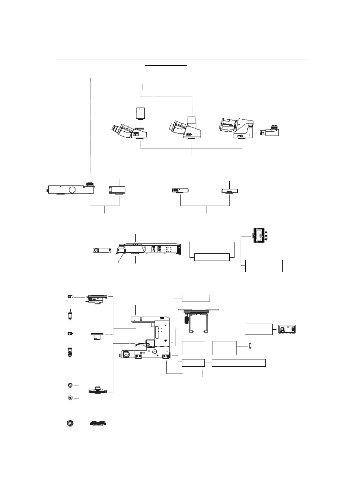
Configuration diagram
Mag. Variable Double Port
③
Trinocular Tube
③
① ②
TV tube
Mag. Variable
Turret
②
C-mount TV camera
C-mount TV adapter
Trinocular Tube
① ② ③
③
Simple Polarizing
Attachment
① ②
Ergonomic
Eyepiece Tube
③
DIC/IR
Analyzer
C-TEP DSC Port
DIC Slider
Objectives
Slider
Objective
(CFI75 LWD)
DIC Module
Support Lens
FL/DIC Analyzer
Sliding Nosepiece
CFI75 Holder
LW D
Condenser
Epi-fl Attachment
①
①
Microscope FN1
High-intensity Light
Source
Motorized Shutter
Mercury Lamp Fiber
Light Source
Magnet Scale
Stage
YM-EPI 3-3PIN
Extention Cable
FN-LPA
Lamp House
Adapter
Light Guide Optical Fiber Light Source
XY Mover
FN-LH
Precentered
Lamp House
Power Suppl
12V100W Halogen Lamp
Polarize
Polarizer Turret
37
Page 40
Chapter 4 Assembly
Installing/removing the lamp and the lamp house (replacing lamps)
1
CAUTION
• To prevent electrical shock and malfunctions, always turn off the
power switched for the power supply and optical fiber light source
(press them to the "O" position), and unplug the power cords from
the wall outlet when installing/removing the lamp house.
• To prevent burn injury, allow the lamp and the lamp house to cool
down sufficiently (for at least 30 minutes after the lamp is turned
off), before replacing lamps.
• Use the Nikon FN-LH model for the lamp house.
• To attach the FN-LH lamp house onto the FN1 microscope body, the
FN-LPA lamp house adapter (optional) is required.
• Use the specified cable (YM-EPI, 3-3PIN extension cable) to connect
the lamp house and the power supply.
• Use a 12V 100W halogen lamp (the PHILIPS 7724 lamp or the OSRAM
HLX64623 lamp).
• Be careful not to touch the glass surface of the lamp with bare
hands. Doing so will cause fingerprints, grease, etc. to burn onto the
lamp surface, reducing the illumination. If you do get any
fingerprints or dirt on the lamp, wipe them clean.
• Make sure the lamp house cover is securely fitted to the lamp house
after replacing lamps. Never use the lamp house while its cover is
Attaching the lamp house
In this section, an example case is explained. (The optical fiber light source has been
connected already.)
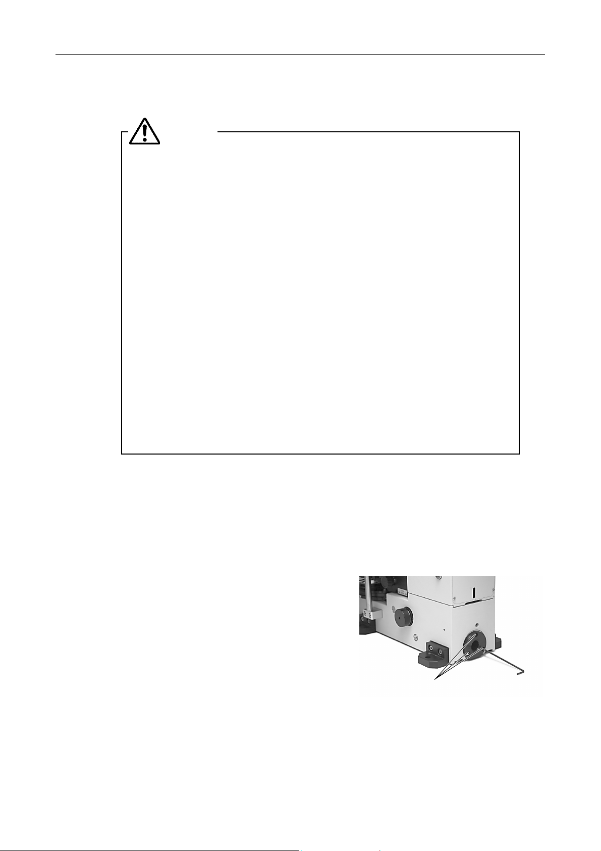
(1) Check that the power switches on the power supply and the optical fiber light source are
(2) Loosen the three M3 hexagonal socket head
off.
turned off (the switches are pushed to the "O" side).
bolts at the standard optical fiber adapter on
the rear side of the microscope body and
remove the standard optical fiber adapter.
38
M3 hexagonal socket
head bolts
Page 41
Chapter 4 Assembly
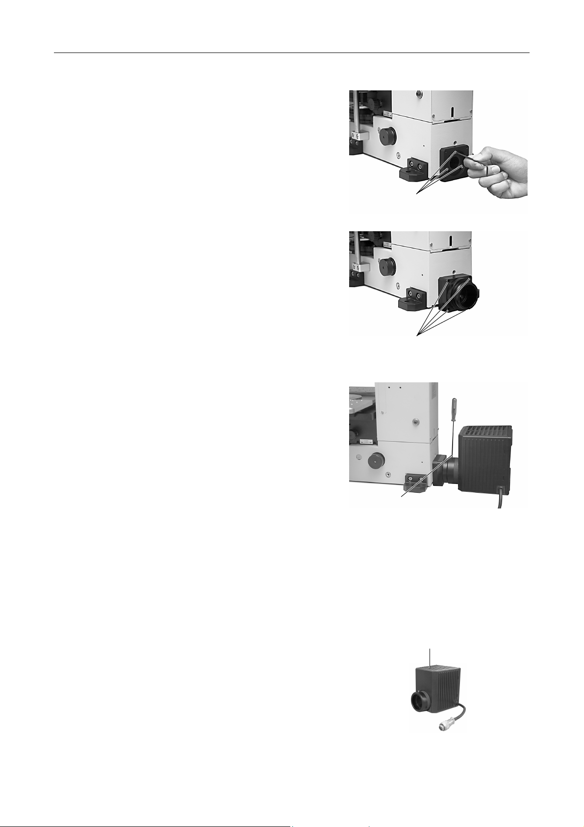
(3) Separate the vertical tube part, which
includes a lens, and the lamp house
connector part of the lamp house adapter.
Insert the vertical tube part only in place of
the optical fiber adapter. And then, fix the
vertical tube part with three M3 hexagonal
socket head bolts.
(4) Attach the lamp house connector part onto
the vertical tube part and fix them with four
M3 hexagonal socket head bolts.
M3 hexagonal socket head bolts
M3 hexagonal
socket head bolts
Replacing lamps
* For information about replacing lamps for the LS-DWL-N halogen light source for the optical fiber
(5) Insert the lamp house into the lamp house
connector part and fix it with the clamp
screw on the upper side of the lamp house.
Clamp screw
illumination, refer to the instruction manual provided with the light source.
(1) Check that the power switches on the power supply and the optical fiber light source are
turned off (the switches are pushed to the "O" side).
(2) Use the hexagonal wrench to loosen the
lamp house clamp screw on the upper side
of the lamp house, then remove the lamp
house cover.
Lamp house cover clamp screw
39
Page 42
Chapter 4 Assembly
A
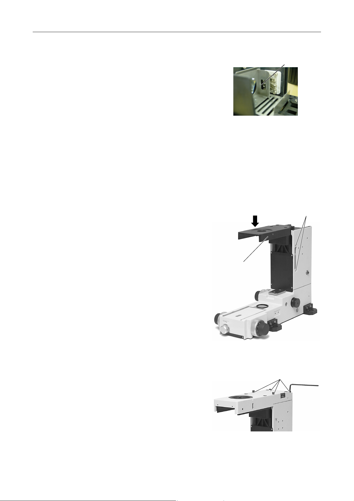
(3) While pressing the lamp clamp lever, push
the lamp into the socket pin holes as far as it
will go. (Don't touch the glass surface of the
lamp with bare hands.)
(4)
Return the lamp clamp lever to its original position. Make sure that the lamp is not tilted.
(5) Attach the lamp house cover securely and tighten the clamp screw. Make sure that the
cover is fixed in place and will not come off even when shaken by hand.
Assembling the nosepiece arm
2
(1) Loosen the two nosepiece arm clamp screws
on the right side of the microscope mainstay
and remove the cover.
(2) Attach the nosepiece arm onto the dovetail
on the microscope mainstay.
ttach the arm
from above
Lamp socket
Nosepiece arm
clamp screws
(3) Tighten the nosepiece arm clamp screw on
the right side of the microscope mainstay.
(4) Reattach the cover on the right side of the
microscope mainstay.
Assembling the eyepiece tube mount part
3
Attach the eyepiece tube mount part onto the
nosepiece arm and fix it with four bolts on the
upper part of the microscope mainstay. Use two
M5-35 bolts for the front side and two M5-30 bolts
for the rear side.
Nosepiece arm
Clamp bolts
40
Page 43
Chapter 4 Assembly
A
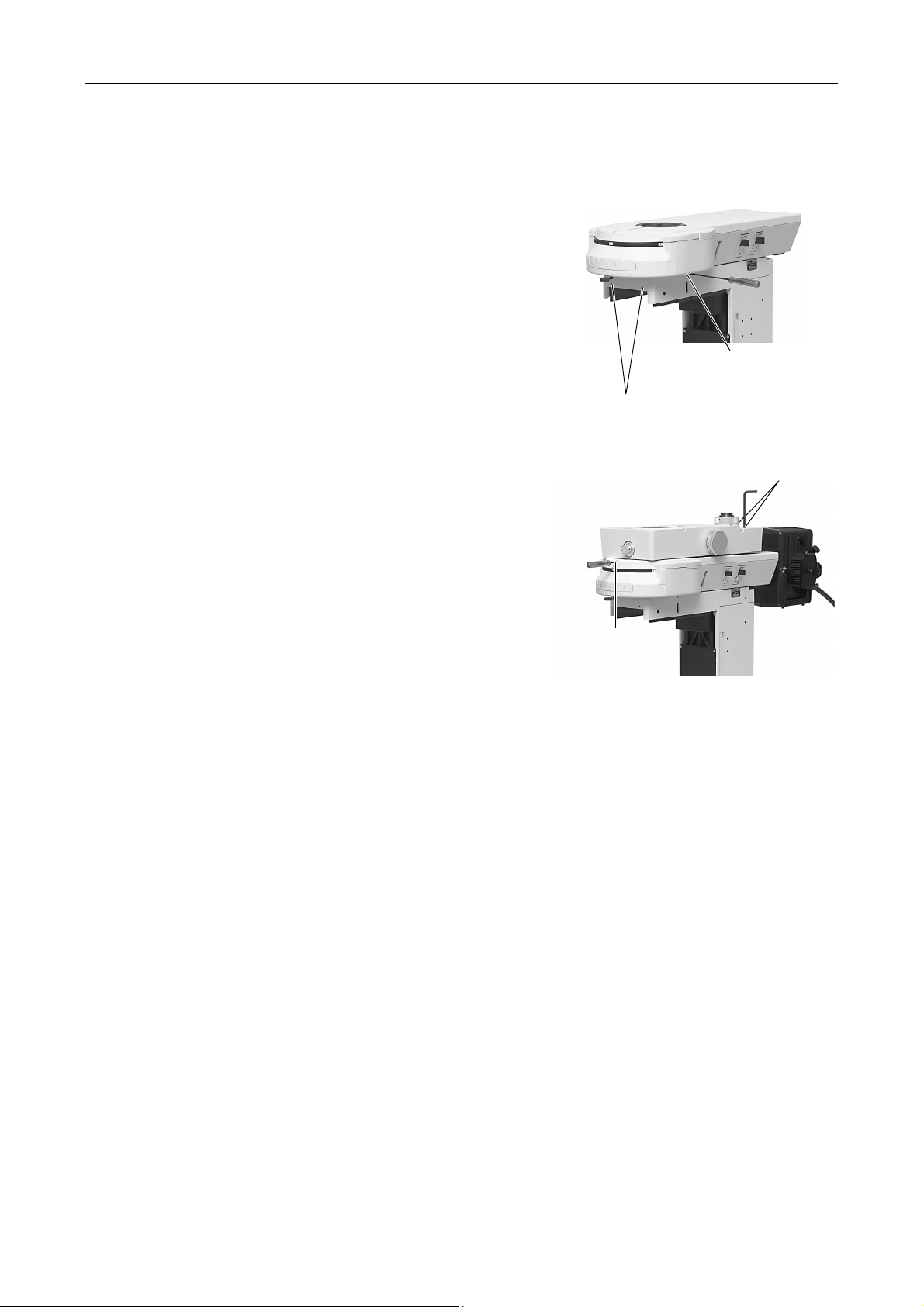
Installing the Epi-fl attachment/variable magnification double port
4
attachment/simple DIC analyzer
1 Epi-fl attachment
(1) Remove the ultraviolet light shield and
the button bolts at the mounting part.
(2) Fix the epi-fl attachment on the
eyepiece tube mount part of the
microscope main body with an M4
hexagonal socket head set screw.
(3) Attach the single objective holder or the
sliding nosepiece. And then, attach the
ultraviolet light shield to the front of the
eyepiece tube mounting part of the
microscope.
2 Variable magnification double port
attachment
Fix the variable magnification double port
attachment on the eyepiece tube mount part
of the microscope main body with an M4
hexagonal socket head set screw.
To use the epi-fl attachment and the variable
magnification double port attachment
together, attach the variable magnification
double port attachment onto the eyepiece
tube mount part of the epi-fl attachment and
fix the double port attachment with an M4
hexagonal socket head set screw. Then, fix
the epi-fl attachment with two M4 hexagonal
socket head bolts onto the microscope main
body. The epi-fl attachment is put between
the microscope main body and the variable
magnification double port attachment.
M4 hexagonal socket head
set screw
ttach the single objective holder or the
sliding nosepiece. And then, attach the
ultraviolet light shield.
M4 hexagonal socket head bolts
M4 hexagonal
socket head set
screw
3 Simple DIC analyzer
Fix the simple DIC analyzer on the eyepiece tube mount part of the microscope main
body with an M4 hexagonal socket head set screw.
To use the simple DIC analyzer with an epi-fl attachment, attach the simple DIC analyzer
onto the epi-fl attachment and fix the analyzer with an M4 hexagonal socket head set
screw.
CAUTION:
When an epi-fl attachment with an analyzer slot is used for this purpose, do
not use the analyzer of the epi-fl attachment.
41
Page 44
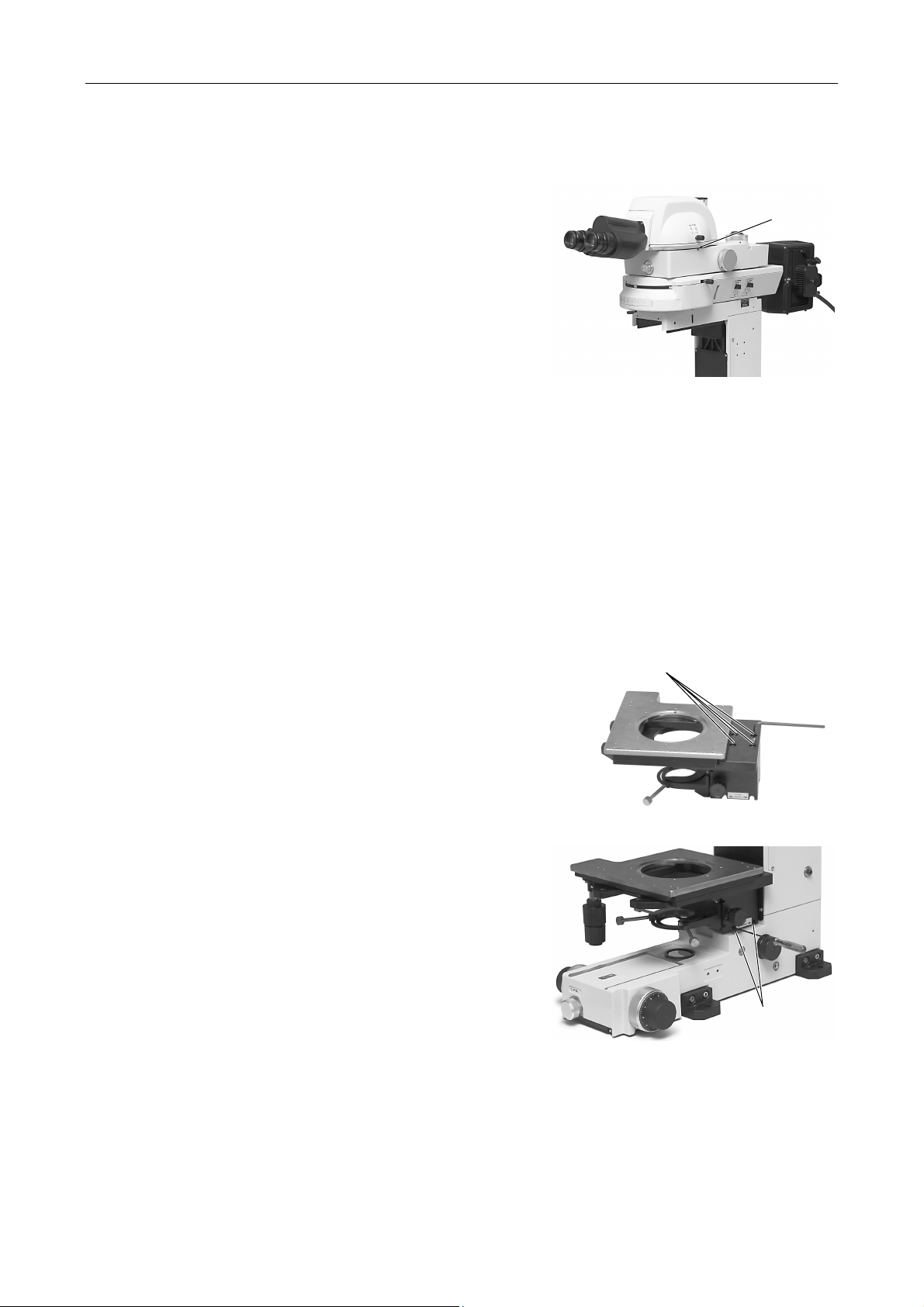
Chapter 4 Assembly
Attaching an eyepiece tube
5
Attach an eyepiece tube on the eyepiece tube
mount part of the microscope main body and fix it
with an M4 hexagonal socket head set screw.
When using an epi-fl attachment, the variable
magnification double port attachment, or the simple
DIC analyzer, attach the eyepiece tube onto the
eyepiece tube mount part of the upper part of the
epi-fl attachment, the variable magnification double
port attachment, or the simple DIC analyzer, and fix
the eyepiece tube with an M4 hexagonal socket
head set screw.
Attaching eyepieces
6
Attach eyepieces of the same magnification.
There is a positioning protrusion on the right sleeve. Align the notch of the eyepiece with the
protrusion on the sleeve and slide in the eyepiece. Some types of eyepiece tube do not have
such protrusions.
M4 hexagonal
socket head
set screw
If necessary, attach optional rubber eye-guards into the grooves around the eyepieces.
Assembling the stage unit and attaching the LWD condenser
7
1 Attaching the stage onto the substage
(1) Remove the four M5 hexagonal socket
(2) Attach the stage onto the substage.
2 Attaching the stage unit onto the
microscope
Take the stage unit assembled in the
previous steps, “Attaching the stage onto the
substage.” Insert the stage unit into the
dovetail of the microscope from the front
side to the limit. And then, fix it with two M4
hexagonal socket head set screws.
head bolts on the upper part of the
substage.
Secure the stage with the four M5
hexagonal socket head bolts removed
in Step (1).
M5 hexagonal socket head bolts
M4 hexagonal
socket head set
42
Page 45
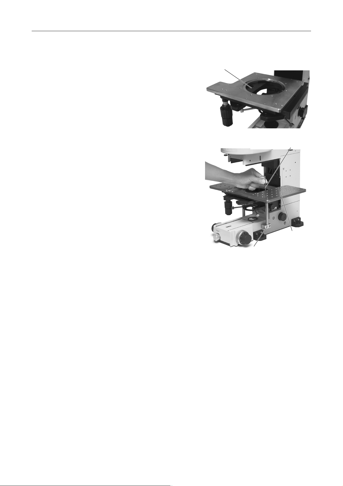
Chapter 4 Assembly
3 Attaching the auxiliary stage support
columns
(1) Move the stage left and right and
around so that you can access the
mounting hole for the auxiliary stage
support column.
(2) Hold an auxiliary stage support column
and bring it to the stage from below.
And then, align its screw hole and the
mounting hole.
(3) Insert a bolt into the mounting hole from
above. Tighten the bolt with a
hexagonal screwdriver to secure the
auxiliary support column to the stage.
Do the same for the opposite side.
(4) Insert a bolt into the threaded hole in
the bottom of the auxiliary support
column, tighten the bolt and secure the
auxiliary support column to the
microscope body. Do the same for the
opposite side.
Mounting hole for the auxiliary
stage support column
Fix the auxiliary support
column to the stage.
* When the LWD condenser is attached, the
stage support columns cannot be
attached. You must attach the stage
support columns before attaching the LWD
condenser.
4 Attaching the stage support plates
Attach the stage support plate onto the
stage. And then, fix it with four bolts. Do the
same for the opposite side.
Fix the auxiliary support column to
* Do the same for the opposite side.
the microscope body.
Stage support
plate
43
Page 46
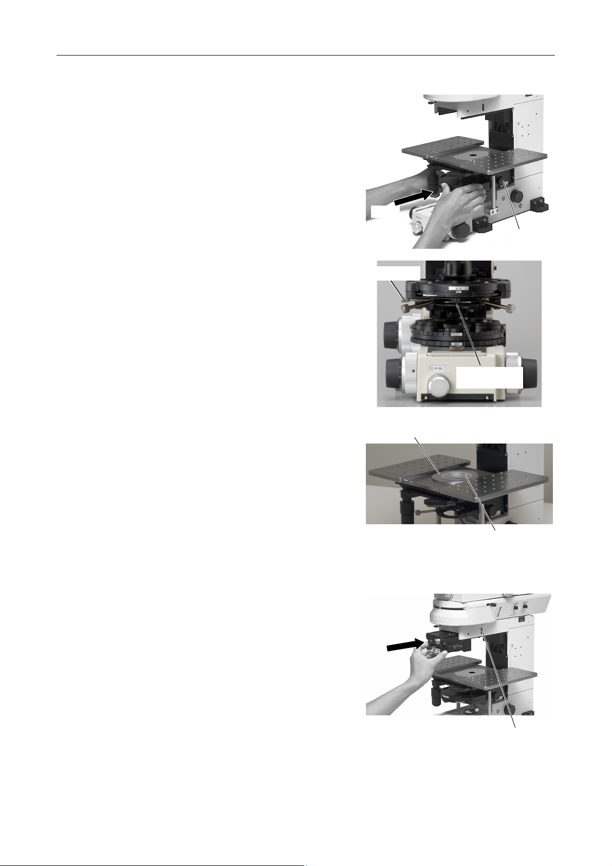
Chapter 4 Assembly
A
5 Attaching the LWD condenser
(1) Rotate the condenser focus knob on
the substage to lower the condenser
holder to the lowermost position. And
then, insert the LWD condenser into the
condenser holder.
(2) Adjust the LWD condenser so that the
aperture diaphragm lever comes to the
front. Then, tighten the clamp screw on
the left side.
Insert
Clamp screw
Condenser
focus knob
perture
diaphragm lever
6 Attaching the chamber holder and the
acrylic chamber
(1) Place the chamber holder on the stage
(2) Adhere a cover glass to the bottom of
Attaching the sliding nosepiece or the single objective holder
8
(1) Rotate the coarse focus knob to move the
nosepiece arm to the center of the vertical
stroke.
(2) Insert the provided hexagonal screwdriver
into the hole on the right side of the
eyepiece mount part. And then, tighten the
M4 hexagonal socket head set screw on the
right side of the arm.
with the flat surface facing up, then
attach the acrylic chamber on the
chamber holder.
the acrylic chamber with a silicone
adhesive or so on to prevent water
leaks.
Chamber holder
Acrylic chamber
(3) Insert the sliding nosepiece or the single
objective holder into the dovetail on the
nosepiece arm.
(4)
Push in the sliding nosepiece of the single
objective holder as far as it will go and fix it
with the M4 hexagonal socket head set screw.
M4 hexagonal socket head set screw
44
Page 47
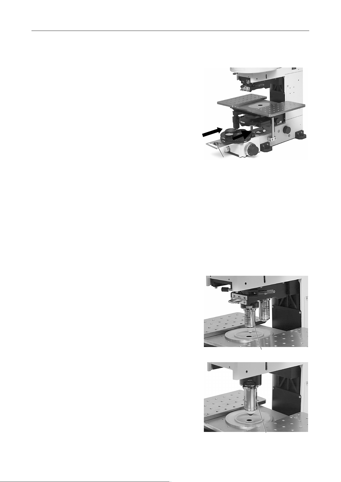
Chapter 4 Assembly
Attaching the polarizer turret
9
10
(1) Insert the polarizer turret into the receptacle
step on the microscope base.
(2) Tighten the clamp screw when the polarizer
turret reaches the limit.
Attaching objectives
For the sliding nosepiece
Rotate the coarse focus knob to move the nosepiece arm to the upper limit.
Move the objective vertical movement lever on the sliding nosepiece to the center. And then, screw
in the nosepieces.
For the sindle objective holder
Clamp screw
Rotate the coarse focus knob to move the nosepiece arm to the upper limit. And then, screw in the LWD
16x water immersion type objective.
11
Attaching the DIC slider
For the sliding nosepiece
Set the objective into the optical path. Lower the
objective. You can see the DIC slider slot. Insert the
DIC slider into the slot.
Use the DIC slider that meets the specifications of
the objective.
For the sindle objective holder
Insert the DIC slider into the DIC slider slot at the
upper part of the clamp screw for the objective.
DIC slider
DIC slider
45
Page 48
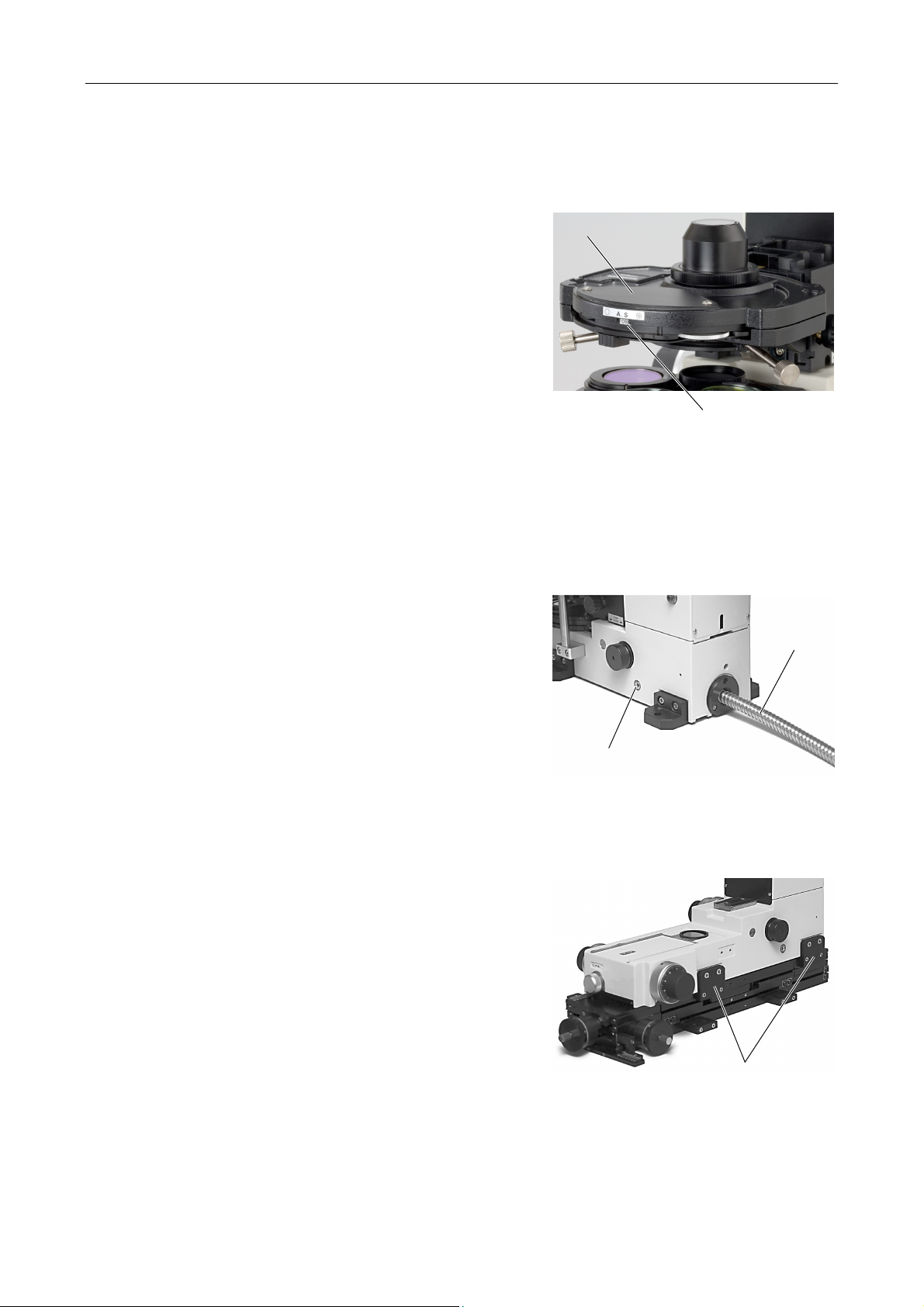
Chapter 4 Assembly
12
13
Attaching the DIC module
Attach the DIC module into the turret of the LWD
condenser.
Loosen the hexagonal socket head screw at the
upper part of the LWD condenser with the hexagonal
screwdriver. And then, remove the cover. You can
see an opening for the DIC module and the diagonal
illumination diaphragm inside the cover. Attach the
DIC module into the opening.
To attach the DIC module N1
Rotate the turret so that you can see the OBL label
at the side of the turret. This is the position to insert
the DIC module N1.
To attach the DIC module N2
Rotate the turret so that you can see the O label at
the side of the turret. This is the position to insert the
DIC module N2.
Connecting the optical fiber light source
(1) Insert the optical fiber into the optical fiber
adapter on the back of the microscope.
(2) Push in the optical fiber as far as it goes, then
fix it with the M4 hexagonal socket head set
screw.
Cover
Label
Optical fiber
adapter
14
Fixing the microscope main body
Insert four hexagonal socket head bolts into the
screw holes on the vibration isolator through the
holes of the base auxiliary legs at the base of the
microscope. And tighten the bolts to fix the
microscope.
To use XY mover manufactured by Narishige
•
Co., LTD
Loosen M5 hexagonal socket head bolts on the
both sides of the microscope base to remove the
base auxiliary legs.
Mount the microscope on the XY mover and align
the screw holes for the base auxiliary legs and
the screw holes on the XY mover. Then, tighten
M5 hexagonal socket head bolts to fix the
microscope.
M4 hexagonal socket
head set screw
XY mover fixing leg
46
Page 49
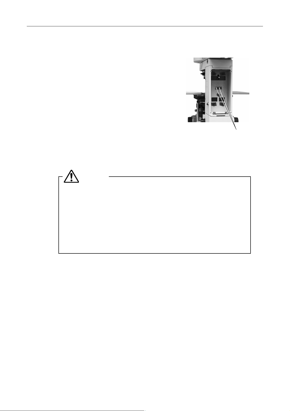
Chapter 4 Assembly
15
Attaching the FN-MS Magnet Scale
(1) Rotate the coarse focus knob to raise the
nosepiece arm to the upper limit.
(2) Loosen four screws using a Phillips
screwdriver to remove the back cover of the
microscope body at the rear side of the arm.
(3) Fix the Magnet Scale into the place with two
M3 screws.
of the Magnet Scale in a slanting
direction.
(4) Draw the cable for the Magnet Scale through
the opening of the back cover. And then,
attach the back cover in place. Connect the
cable to the [SIG. IN] socket on the back of the
display part of the Magnescale.
16
Connecting the power code
Do not place the detector part
WARNING
Make sure to use the specified power cord.
Screw holes for
the Magnet Scale
• When the supply voltage is 100 V to 120 V, the power cord specification
is as follows.
• UL Listed detachable cord set, 3 conductor grounding Type SVT, No.18
AWG, 3 m long maximum, rated at 125 VAC minimum.
• When the supply voltage is 220 V to 240 V, the power cord specification
is as follows.
• Approved according to EU/EN standards, 3 conductor grounding Type
Connect the lamp house and the power supply with the extension cable.
Check that the power switch on the power supply is turned off (it is flipped to the "O" side).
Insert the socket of the power cord into the AC inlet on the back of the power supply. Then,
securely plug the power cord to the wall outlet.
HO5VV-F, 3 m long maximum, rated at 250 VAC minimum.
47
Page 50
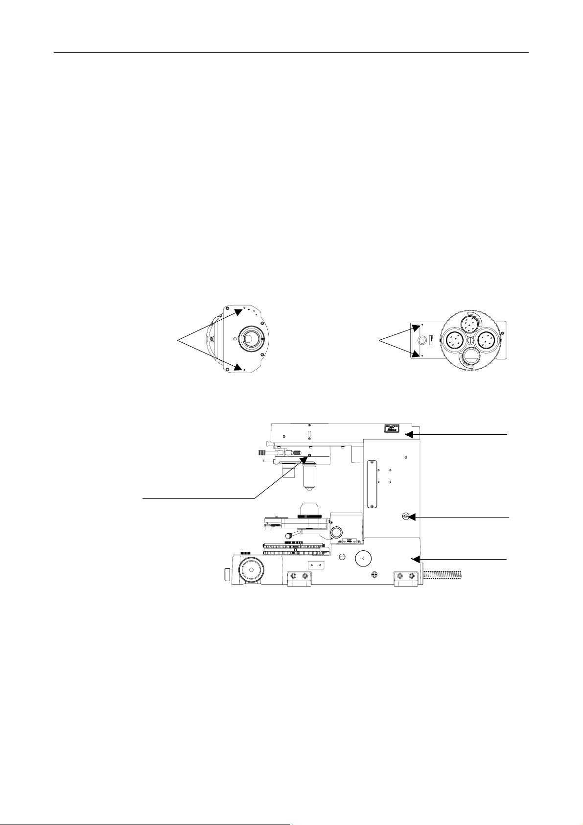
Chapter 4 Assembly
17
Attaching cables to reduce noise
There are screw holes on the microscope body and on the accessories to attach cables to
reduce noise.
Microscope body
Eyepiece tube mount part: one M3 screw hole on the right side
Mainstay: one M4 hexagonal socket head bolt on the right side
Lower part of the body: one M3 screw hole on the right side
Sliding nosepiece: two M3 hexagonal socket head bolts on the both sides
LWD condenser: two M4 screw holes on the bottom side
Polarizer turret: two M3 screw holes
M4 screw holes
LWD condenser (bottom side)
M3 screw holes
FN-PT
JAPAN
Polarizer turret
M3 screw hole
M3 hexagonal socket head bolt
18
(both sides)
Microscope body
Attaching option accessories
To attach option accessories such as the photomicrographic equipment or so on, refer to the
instruction manuals for them.
M4 hexagonal
socket head bolt
M3 screw hole
48
Page 51

Troubleshooting
5
Improper use of the microscope may adversely affect performance, even if the microscope is
not damaged. If any of the problems listed in the table below arise, take the countermeasures
indicated.
1
Viewing Problems and Control Problems
Problem Cause Countermeasure
The optical path selector lever on
the eyepiece tube is in an
intermediate position.
The optical path selector lever on
the eyepiece tube is not placed to
the position of 100% distribution
to the binocular part.
The nosepiece is not placed to a
click-stop position. (The objective
is not placed in the optical path).
The clicking level is set to the
weak touch.
Securely move the optical path selector lever to
the position where 100% light goes through the
binocular eyepiece.
Push the slide click release button and slide the
sliding nosepiece to the click-stop position.
The viewfield is invisible,
vignetted, or uneven in
brightness.
Dirt or dust is seen in the
viewfield.
The condenser position is too low.
The condenser has not been
centered.
The condenser is not attached
correctly.
A filter is in an intermediate
position.
The field diaphragm is stopped
down too far.
The optical fiber is not attached
correctly.
The condenser position is too low.
The aperture diaphragm is
stopped down too far.
Adjust the condenser focus knob so that the
field diaphragm image is focused on the
specimen surface.
Center the condenser.
Install the condenser correctly.
Move the filter slider to a click-stop position.
Open the diaphragm to a suitable size.
Install the optical fiber correctly.
Adjust the condenser focus knob so that the
field diaphragm image is focused on the
specimen surface.
Open the diaphragm to a suitable size.
Dirt or dust exists on the
objective, condenser, eyepieces,
filters, specimen, or optical path.
Clean the components.
49
Page 52

Chapter 5 Troubleshooting
1 Viewing Problems and Control Problems
Problem Cause Countermeasure
The viewing is poor (too much
or too little contrast, or poor
resolution).
The focus is uneven.
The aperture diaphragm is
stopped down too far.
The condenser position is too low.
There is oil or water at the tip of
the dry type objective.
There is a bubble in the
immersion water at the tip of the
water immersion type objective.
The orientation adjustment of DIC
parts has not been performed.
Dirt or dust exists on the
objective, condenser, eyepieces,
filters, specimen, or optical path.
The nosepiece is not placed to a
click-stop position.
The specimen is not secured in
place on the stage surface.
Open the diaphragm to a suitable size.
Adjust the condenser focus knob so that the
field diaphragm image is focused on the
specimen surface.
Clean the components.
Raise the objective. And then, remove the
bubble from the water.
Adjust the polarizer orientation correctly.
Clean the components.
Push the slide click release button and slide the
sliding nosepiece to the click-stop position.
Attach the specimen securely.
The image is elongated.
The image is tinged yellow.
The image is too bright.
The stage is tilting. Install the stage correctly.
The nosepiece is not placed to a
click-stop position.
The specimen is not secured in
place on the stage surface.
The condenser has not been
centered.
The stage is tilting. Install the stage correctly.
The NCB11-A filter is not used. Place the NCB11-A filter into the optical path.
The lamp voltage is too low.
The lamp voltage is too high.
Push the slide click release button and slide the
sliding nosepiece to the click-stop position.
Attach the specimen securely.
Center the condenser.
Adjust the brightness with the brightness
control knob on the power supply.
Adjust the brightness with the brightness
control knob on the power supply.
50
Page 53

Chapter 5 Troubleshooting
1 Viewing Problems and Control Problems
Problem Cause Countermeasure
The brightness is insufficient.
(Refer to the troubleshooting
for the electric system too.)
The specimen goes out of focus
when the objectives are
switched.
The specimen movement is too
sensitive.
When viewing through the
binocular eyepiece, the image
does not resolve into a single
image.
The lamp voltage is too low.
The aperture diaphragm is
stopped down too far.
The condenser position is too low.
The diopter adjustment has not
been performed.
Parfocal adjustment for objectives
has not been performed.
The torque for the stage handle is
adjusted too light.
The interpupillary distance has
not been adjusted.
The diopter adjustment has not
been performed.
The interpupillary distance has
not been adjusted.
Adjust the brightness with the brightness
control knob on the power supply.
Open the diaphragm to a suitable size.
Adjust the condenser focus knob so that the
field diaphragm image is focused on the
specimen surface.
Adjust the diopters.
Perform parfocal adjustment.
Adjust the torque tighter.
Adjust the interpupillary distance.
Adjust the diopters.
Adjust the interpupillary distance.
Eye strain develops while
viewing.
The diopter adjustment has not
been performed.
The brightness is not appropriate.
Adjust the diopters.
Adjust the brightness with the brightness
control knob on the power supply.
51
Page 54

Chapter 5 Troubleshooting
2 Electrical System Problems
2
The lamp does not light even
though the power switch is
turned on.
Electrical System Problems
Problem Cause Countermeasure
The power cord is not connected
to a wall outlet.
The power cord is not connected
to the AC inlet on the power
supply.
The extension cable is not
connected to the power supply.
The extension cable is not
connected to the lamp house.
No lamp is attached. Attach a lamp.
The lamp is blown. Replace the lamp with a new one.
A wrong lamp is used.
The lamp is about to blow. Replace the lamp with a new one.
Plug the power cord into a wall outlet.
Connect the power cord to the AC inlet on the
power supply.
Connect the extension cable to the power
supply.
Connect the extension cable to the lamp house.
Use the specified lamp (PHILIPS 7724 or
OSRAM HLX 64623).
The lamp flickers, or its
brightness is unstable.
The power cord is not connected
securely.
The lamp is not securely inserted
into the socket.
The lamp house is not connected
securely.
Connect the power cord securely.
Insert the lamp securely.
Connect the power cord securely.
52
Page 55

6
Care and Maintenance
Lens cleaning
1
Do not let dust, fingerprint, etc. get on the lenses. Dirt on the lenses, filters, etc. will adversely
affect the view of image. If any of the lenses get dirty, clean them as described below.
• Either brush away dust with a soft brush, or else gently wipe it off with a piece of gauze.
• Only if there are fingerprints or grease on a lens, dampen lightly a piece of soft, clean
cotton cloth, lens tissue, or gauze with absolute alcohol (ethyl or methyl) and gently wipe
off the dirt.
• Use petroleum benzine to clean off immersion oil.
• Do not use petroleum benzine to wipe the entrance lens in the eyepiece tube.
• Absolute alcohol and petroleum benzine are highly flammable. Be careful when handling
it, when around open flames, when turning the power switch on/off, etc.
• When using petroleum benzine or absolute alcohol, always follow the instructions
provided by the manufacturer.
Painted component cleaning
2
Do not use organic solvents such as alcohol, ether, or paint thinner on painted components,
plastic components, or printed components. Doing so could result in discoloration or in
peeling of the printed characters. For persistent dirt, dampen a piece of gauze with neutral
detergent and wipe gently.
Storage
3
Store this product in a dry place where mold is not likely to form.
Store the objectives and eyepieces in a desiccator or similar container with a drying agent.
Put the dust-proof cover over this product to protect it from dust.
Before putting on the dust-proof cover, turn off the power switch of the power supply (flip it to
the "O" position) and wait until the lamp house gets cool sufficiently
Regular inspection
4
Regular inspection of this microscope system is recommended to maintain peak performance.
Contact your nearest Nikon representative for details.
53
Page 56

Specifications
7
■ Nikon microscope ECLIPSE FN1
Model name ECLIPSE FN1
Main body
Optical system
Main body
Focusing mechanism
Nosepiece
Stage Triple plate type rectangular stage
Eyepiece section Binocular eyepiece tube (Bino 100%)
CFI60 and CFI75 optical system (infinity-corrected CF optical system)
"I" shape body, external power supply system
Nosepiece up/down mechanism
Manual operation type single axis coarse/fine focus knob mechanism (coarse/fine
knobs are located at both sides)
Sliding nosepiece (for CFI60 objectives):
•
Back and forth sliding type, double sockets, DIC prism attachable
Single objective holder (for CFI75 objectives):
•
Single socket, DIC prism attachable
Movable range: 30 (X) x 27.5 (Y) mm
Ergonomic eyepiece tube (Bino 100%, Bino : DSC port = 50% : 50%)
* The DSC port cannot be used with the variable magnification double port tube.
Trinocular eyepiece tube FUW (Bino : Vertical port = 100% : 0%, 0% : 100%)
Trinocular eyepiece tube TUW (Bino : Verticlal port = 100% : 0%, 20% : 80%,
0% : 100%)
Long object distance
condenser
Eyepiece 10x, field number 22, 25
Light source
TE2-PS100W power
supply
Universal turret condenser
NA: 0.78
Object distance (OD): 8.2mm
Differential interference contrast microscopy and diagonal illumination microscopy
can be performed.
Lamp house: (12V 100W long-life halogen lamp)
•
precentered type
(specified lamp house: FN-LH precentered lamp house)
(specified lamp: PHILIPS 7724 or OSRAM HLX 64623)
Optical fiber: (12V 100W halogen lamp)
•
(specified light source: halogen light source LS-DWL-N manufactured by
Sumita Optical Glass Inc.
Input ratings: 100 to 240 VAC, 50/60Hz, 2.4A
Voltage fluctuations: ±10%
Output ratings: 12VDC 100W, 8.4A
Electric shock protection class: class 1
Safety standards: Ul listed product, GS approved
54
Page 57

Chapter 7 Specifications
Power cord
Operating conditions Temperature: +10°C to +40°C
Transport/storage
conditions
External dimensions
and weight (main body)
Safety standard
Eclipse FN1 and the
following equipment
were tested for the UL
certification.
TE2-PS100W
•
power supply
FN-LH lamp house
•
YM-EPI, 3-3PIN
•
extension cable
• When the supply voltage is 100 V to 120 V
UL Listed detachable cord set, 3 conductor grounding Type SVT, No.18
AWG, 3 m long maximum, rated at 125 V AC minimum.
• When the supply voltage is 220 V to 240 V
Approved according to EU/EN standards, 3 conductor grounding Type
HO5VV-F, AWG 18, 3 m long maximum, rated at 250 V AC minimum.
• To use the halogen light source LS-DWL-N (manufactured by Sumita Optical
Glass), be sure to use the provided power cord.
Humidity: 85% RH max. (no condensation)
Altitude 2000 m max.
Pollution degree Degree 2
Installation category Category II
Electric shock protection class Class I (TE-PS100W power supply)
Indoor use only
Temperature: -20°C to +60°C
Humidity: 90% RH max. (no condensation)
External dimensions: 214(W) x 346(H) x 422(D) mm
Weight: approx. 12 kg
• This is UL-listed product. (UL61010A-1)
• This product meets FCC Part 15B Class A requirements.
This equipment has been tested and found to comply with the limits for a
Class A digital device, pursuant to Part 15 of the FCC Rules.
These limits are designed to provide reasonable protection against harmful
interference when the equipment is operated in a commercial environment.
This equipment generates, uses, and can radiate radio frequency energy and,
if not installed and used in accordance with the instruction manual, may
cause harmful interference to radio communications.
Operation of this equipment in a residential area is likely to cause harmful
interference in which case the user will be required to correct the interference
at his own expense.
• This Class A digital apparatus complies with Canadian ICES-003.
This Class A digital apparatus complies with Canadian ICES-003.
Cet appareil numérique de la classe A est conforme à la norme NMB-003 du
Canada.
• This product complies with Australian EMC (AS/NZS CISPR11 Group 1 Class
B).
CE marking
• This product meets EU Low Voltage Directive requirements.
• This product meets EU EMC Directive requirements.(EN61326)
55
Page 58
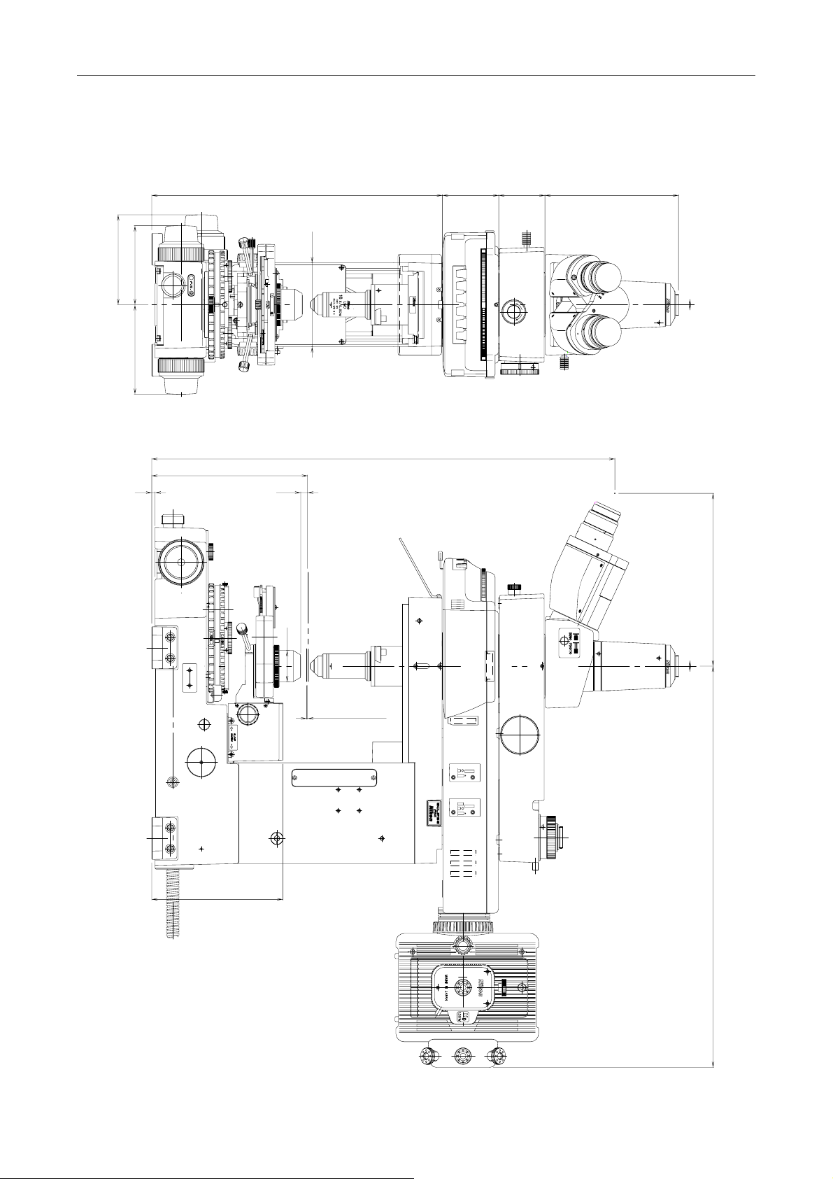
Chapter 7 Specifications
Outer dimensions
■
100
107
94
106.5
4
185.5
A.S
8.2
551.2
FN-MN-H
JAPAN
1
2
3
CO
1
4
SHUTTER
5
6
26
IN
D
M
O
U
T
0.35
159 55 67 346
FN1 and trinocular eyepiece tube
156
φ37
Specimen surface
1(coverslip)
205.5 477.5
2
F
.
S
T
O
P
E
A
X
.
.
A
S
D
J
T
.
O
P
56
Page 59
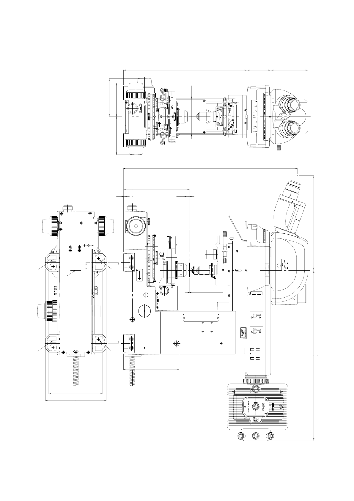
Chapter 7 Specifications
4
FN1 and ergonomic eyepiece tube
104 67 346
100
107
94
F
N
S
2
N
J
A
P
A
A.S
N
106.5
6
1
2
3
CO
1
4
SHUTTER
5
6
2
486.7
185.5
Specimen surface
264.6 477.5
2
φ37
φ9
21.8
Optical path center
φ9
1(coverslip)
226.8
F
.
S
T
O
P
A
E
X
.
.
S
A
D
T
J
O
.
P
φ9
φ9
156
151.4
170
57
 Loading...