

Page 1

Microscope
ECLIPSE 80i
Instructions
<Microscopy>
M318E 03.12.CF.1(1/2)
Page 2

Page 3
1
Introduction
Thank you for purchasing this Nikon product.
This instruction manual, which describes basic microscope operations, is intended for users of the Nikon ECLIPSE 80i
microscope.
To ensure correct use, please read this manual carefully before operating the product.
• This manual may not be reproduced or transmitted in whole or in part without Nikon's express consent.
• The contents of this manual are subject to change without notice.
• Although every effort has been made to ensure the accuracy of this manual, errors or inconsistencies
may remain. If you note any points that are unclear or incorrect, please contact your nearest Nikon
representative.
• Some of the products described in this manual may not be included in the set you have purchased.
• Make sure you have read the manuals for any other products attached to or to be used with this
microscope (super high-pressure mercury lamp power supply, high-intensity light source, etc.).
Warning/Caution symbols used in this manual
Although Nikon products are designed to provide the utmost safety, ignoring safety precautions or improper use may
result in personal injury or property damage, as well as voiding the terms of the warranty. To ensure safe use, please
read the instruction manual carefully and thoroughly before trying to operate the instrument. Do not discard this
manual. Store in a convenient location near the product for ready reference.
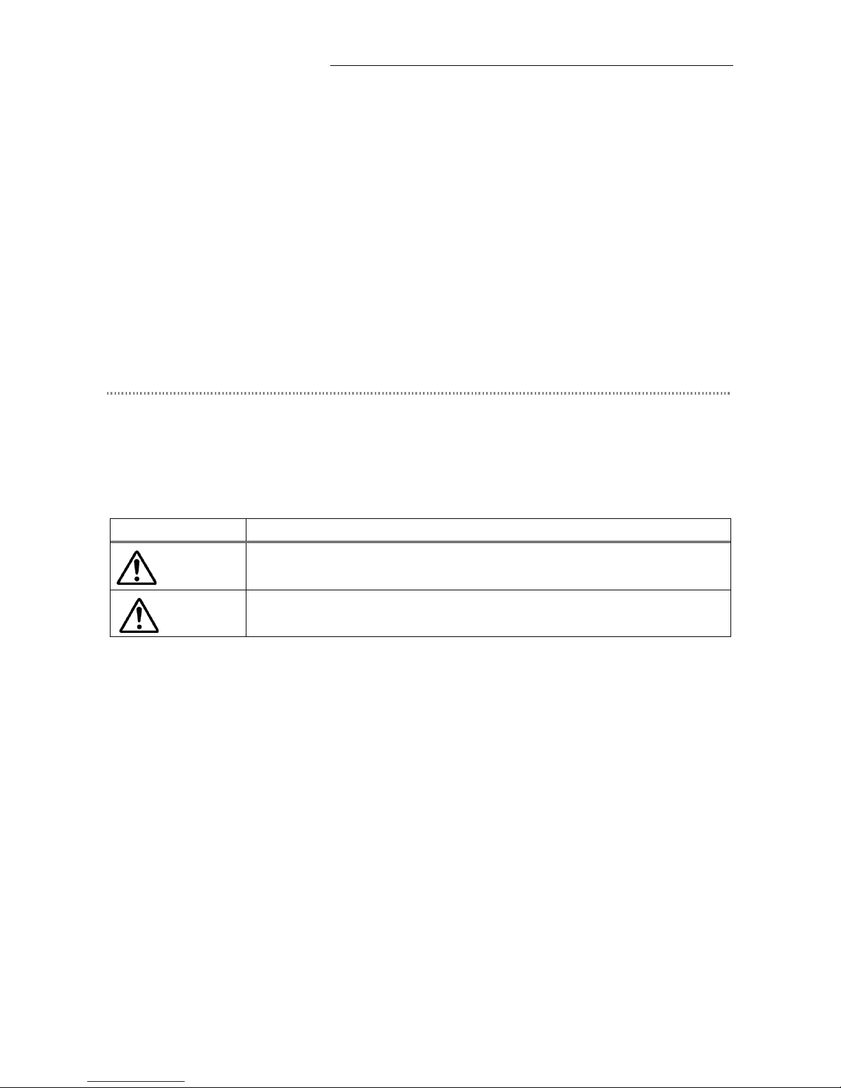
In this manual, safety precautions are indicated by the following symbols. For safe, correct use of the microscope,
always follow the instructions indicated by these symbols.
Symbol Meaning
Disregarding instructions indicated by this symbol may result in death or serious
injury.
Disregarding instructions indicated by this symbol may result in injury or property
damage.
WARNING
CAUTION
Page 4
Introduction
2
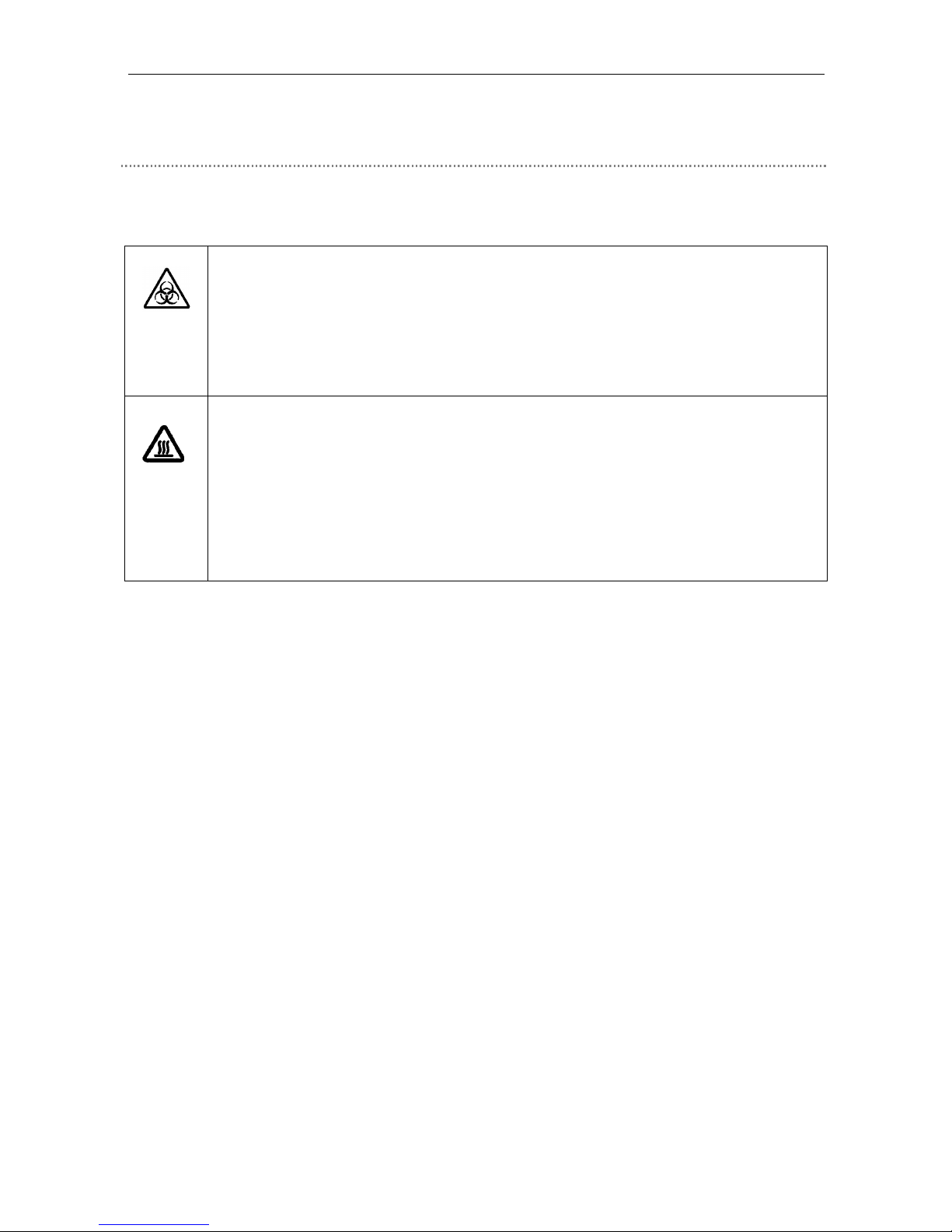
Meaning of symbols used on the product
When appearing on the product, the symbols below indicate the need for caution at all times during use.
Consult the instruction manual and read the relevant instructions before attempting to use or adjust any part to which
the symbol has been affixed.
Caution! Biohazard
This symbol found on the stage indicates the following:0
• WARNING: Contact between sample and microscope may result in biohazard risks.
• To avoid biohazard contamination, avoid touching the contaminated portion with bare hands.
• Decontaminate the contaminated part according to the standard procedure specified for your
laboratory.
Caution for heat
This symbol found on the lamphouse of the ECLIPSE 80i indicates the following:
• The lamp and surrounding areas (including the lamphouse) become very hot during and
immediately after a period of illumination.
• Risk of burns. Do not touch the lamp or surrounding areas during or immediately after a
period of illumination.
• Make sure the lamp and surrounding areas have cooled sufficiently before attempting to
replace the lamp
Page 5

3
Safety Precautions
Please follow the safety precautions given below.
1. Intended use of the product
This product is intended primarily for microscopic observations of cells and tissue set on glass sides
using diascopic (transmitted) and episcopic illumination.
It is intended for use in experimentation and observation of cells and tissue in the fields of pathology
and cytology in hospital and other laboratory settings.
2. Do not disassemble.
Disassembly may result in malfunctions and/or electrical shock and will void the terms of the warranty.
Never attempt to disassemble any part other than the parts described in this manual. If you experience
problems with the product, contact your nearest Nikon representative.
3. Read the instruction manuals carefully.
To ensure safety, carefully read this manual and the manual provided with any other equipment used
with this product. Observe all warnings and cautions given at the beginning of each manual.
When the digital imaging head or the D-FL Epi-illumination attachment is attached to the
microscope
The mercury lamp (or xenon lamp) for Epi-fl microscopy requires special care during handling. Make
sure you have read the instruction manual for the light source (super high-pressure mercury lamp
power supply or high-intensity source).
4. Power cord for microscope and the power cord for AC adapter
Use one of the power cords specified. Using the wrong power cord may result in fire or other hazards.
The product is classified as subject to Class I protection against electrical shock. Make sure it is
connected to an appropriate ground terminal.
Refer to Chapter 8 for the power cords specified.
To prevent electric shock, always turn off the main power switch (press it to the "{" position) of the
product before attaching or detaching the power cord.
5. Inspect the AC adapter (when using the D-CB C-BOX).
The D-CB C-BOX is powered by an AC adapter. Use only the specified adapter model meeting the
requirements. Using any other type of adapter may result in malfunction, overheating, and/or fire.
Refer to Chapter 8 for the adapter specified.
• To prevent malfunctions and/or fire, use the AC adapter in a well-ventilated location. To ensure
proper heat radiation and to prevent overheating, never cover or place any object on the adapter.
• To prevent malfunctions, always turn off the power switch (the switch is in the out position) of the
C-BOX before attaching the AC adapter.
WARNING
Page 6

Safety Precautions
4
6. Heat from the light source
The lamp and surrounding areas (including the lamphouse) will become very hot during and
immediately after a period of illumination.
• Risk of burns. Never touch the lamp or surrounding areas during or immediately after a period of
illumination.
• Make sure the lamp and surrounding areas have cooled sufficiently before attempting to replace the
lamp
• To avoid risk of fire, do not place fabric, paper or highly flammable volatile materials such as
gasoline, petroleum benzine, paint thinner or alcohol near the lamphouse while the lamp is lit or
during a period of around thirty minutes after the lamp has been turned off.
7. Mercury lamps and xenon lamps (when the digital imaging head or the D-FL Epi-illumination
attachment is attached)
The mercury lamp (or xenon lamp) for the digital imaging head or the D-FL Epi-illumination
attachment requires special care during handling. For safe and correct use of this system, carefully
read the warnings below. Keep in mind all potential hazards. Additionally, carefully read the manual for
the super high-pressure mercury lamp power supply (or high-intensity light source) and the manual (if
provided) from the lamp manufacturer, then follow the instructions given therein.
Hazards of Mercury Lamps and Xenon Lamps
1) When lit, mercury (and xenon) lamps radiate ultraviolet light that can damage your eyes and skin.
Direct viewing of the light may result in blindness.
2) The lamps contain sealed gas under very high pressure, pressure that increases when the lamp is on.
If the lamp is scratched, fouled, subjected to high external pressure or physical impact, or used
beyond its service life, the sealed gas may escape or the lamp may burst, resulting in gas inhalation,
injury from glass, or other injury.
3) When the lamp is lit, the lamp and surroundings will become extremely hot. Touching the lamp with
bare hands may result in burns; flammable materials placed near the lamp may ignite.
4) Using the wrong lamp type may result in accidents, including bursting of the lamp.
Safety is a top design priority for Nikon products. The preceding hazards should pose no danger as
long as the user observes all of the warnings and cautions given in the manuals, and uses the system
only for its intended purpose.
However, failure to heed the warnings and cautions given in the manuals, subjecting the system to
shock or impact, or attempting to disassemble the system may result in accidents and injury. Make
sure you are familiar with and adhere to all warnings and cautions.
8. Always turn off the lamp when changing filter cubes (when the digital imaging head or the D-FL
Epi-illumination attachment is attached to the microscope).
When changing filter cubes, always turn off the digital imaging head or the D-FL Epi-illumination
attachment. Leaving the lamp on may result in ultraviolet exposure.
9. Leave the D/UV slider in the optical path (when using the digital imaging head or the D-FL
Epi-illumination attachment).
Always leave the D/UV slider (which is one of the D-ES EPI ND slider types) in the optical path when
performing Epi-bright-field microscopy, Epi-dark-field microscopy, or Epi-DIC microscopy with the
mercury lamphouse attached. If the slider is moved out of the path, ultraviolet light will be radiated
and damage your eyes.
WARNING
Page 7
Safety Precautions
5
10. Hazardous Sample
This microscope is intended primarily for microscopic observations of cells and tissue set on glass
sides.
Check to determine whether a sample is hazardous before handling.
Handle hazardous samples according to the standard procedure specified by your laboratory.
If the sample is potentially infectious, wear rubber gloves and avoid touching samples. If contact
occurs between a sample and the microscope, decontaminate the contaminated portion according to
the standard procedure specified for your laboratory.
1. Turn off power during assembly, connection/disconnection of cords, lamp replacement, and
maintenance.
To prevent electric shock and/or malfunctions, always turn off the power switch(es) of the product
(press it (them) to the "!" position) and unplug the power cord from the wall outlet before assembly,
connecting or disconnecting of cords, lamp replacement, and cleaning of the microscope and the
objective.
2. Lamp replacement precautions
To avoid burns, wait at least 30 minutes after the lamp is turned off to give it sufficient time to cool.
To avoid electric shock or malfunctions, never attempt to replace the lamp without first turning off the
power switches for the microscope and the peripheral devices (press them to the "!" position) and
unplugging the power cord from the wall outlet.
Make sure the lamphouse cover is securely fitted to the lamphouse after lamp replacement. Never turn
on the lamp while the lamphouse cover is open. Do not break up used lamps; instead, dispose of them
as special industrial waste or as specified by local regulations.
3. Use the specified lamp and lamphouse.
Always use the specified lamp and lamphouse. Using an unspecified lamp may cause malfunction or fire.
Refer to Chapter 8 for the specified lamp and lamphouse.
4. Avoid contact with water.
Never allow water to come into contact with the product, and keep the product away from liquids.
Splashing water onto the product may cause a short, resulting in malfunction or abnormal heating. If
water is splashed onto the product, immediately turn off the power switch (press it to the "!" position)
and remove the power cord from the receptacle. Then wipe off moisture with a dry cloth or something
similar. If water enters the product, do not use; in this case, contact your distributor.
5. Do not place any object on top of the product.
Do not place any object on top of the product or cover it with a cloth or the like. The system
temperature will rise, resulting in malfunctions.
CAUTION
WARNING
Page 8

Safety Precautions
6
6. Cautions on assembling and installing the microscope
• Take care to avoid pinching your fingers or hands during microscope assembly.
• Scratches or fouling such as fingerprints on optical components (such as lens and filters) will
degrade microscope images. Be careful to avoid scratches or direct contact with the lens and filters.
• The main unit weighs about 12 kg. Grasp the main unit by the recesses at the front of the arm and
at the bottom of the main unit.
• Remove all attachments (if attached) from the microscope before carrying the microscope.
• Do not install the product in a locker or cabinet.
7. Remove any covers from the product before switching on.
Do not use the product while covered with a cloth, etc., as this will give rise to abnormal heat, which
could cause a fire.
8. Caution concerning long, sustained observations
To relieve fatigue resulting from long observation sessions, limit continuous observations to one hour.
Take at least 10- to 15-minute breaks between observation sessions. Adjust the layout of other
equipment (such as the display and the mouse) and match to the position of the product and the height
of your chair.
9. Disposal of the product
To avoid biohazard risks, dispose of the product as contaminated equipment according to the standard
procedure specified for your laboratory.
CAUTION
Page 9

Notes on handling the product
7
Notes on handling the product
1. Handle the product gently.
This product is a precision optical instrument and requires gentle handling. Avoid subjecting it to sudden
impact and shocks.
Even relatively minor impacts are capable of affecting the precision of the object.
2. Weak electromagnetic waves
The product emits weak electromagnetic waves. Do not place precision electronic devices near the
product to avoid degrading their performance. If TV or radio reception is affected, move the TV or radio
farther away from the product.
3. Scratches, dirt, and foreign particles on the lens
Scratches or fouling such as fingerprints on optical components (such as lens and filters) will degrade
microscope images. If these parts become dirty, clean them as described in chapter "7. Care and
maintenance" at the end of this manual.
4. Dirt on the lamps
Never touch the lamp with bare hands. Dirt or fingerprints on the lamp will result in uneven illumination
and reduce the service life of the lamp. Always wear gloves when handling lamps.
5. Installation location
This product is a precision instrument. Use or storage in inappropriate environments may result in
malfunctions or poor performance. Consider the following factors when selecting an installation location:
• Select a vibration-free location. Install the product on a level surface.
• Install the product at least 10 cm away from walls.
• Choose a location less exposed to hazards in the event of collisions, earthquakes, or other potential
disasters. To keep the product from falling, use strong rope or other means if necessary to secure it
to the working desk or to another heavy, stable item. To fix the microscope, there are two M6 screw
holes (one at the right and the other at the left) behind the recess at the base of the main body
(back side).
• Avoid locations exposed to direct sunlight, locations immediately under room lights, and other bright
locations.
• Avoid locations with excessive dust.
• Do not install the product near any liquid.
• Make sure the ambient temperature is 0 to 40°C and humidity is 85% or less. Installing the 80i in hot,
humid locations may result in mildew formation or condensation, impairing performance or
generating malfunctions.
• Do not install the product in a locker or cabinet.
• Select a layout that allows easy removal of the power cord from the product's AC inlet in the event of
an emergency.
• Room lights just above the microscope may reduce visibility in the objective as extraneous light. If
possible, switch off room lights directly above the microscope when making observations.
Page 10

Notes on handling the product
8
6. Focusing knobs
• Never turn the focus knobs on the left and right sides of the microscope in opposite directions at the
same time. Doing so may damage the microscope.
• Turning the coarse focus knob past its farthest point will damage the microscope. Never use undue
force when turning the knob.
7. Protect the ports from dust and extraneous light (when the trinocular eyepiece tube, the digital
imaging head, or the C-TE ergonomic binocular tube is attached).
To keep out extraneous light and dust, always attach the supplied cap to any port not currently in use.
8. Handling of filters (when the digital imaging head or the D-FL Epi-illumination attachment is
attached to the microscope)
• Interference filters (especially excitation filters, which are exposed to strong light) degrade over time.
Replace them after the appropriate hours.
• Filter characteristics may alter if the filter is exposed to high humidity. To prevent changes in or
degradation of filter characteristics, avoid using or storing the filters under conditions of high humidity
or high temperature. Avoid subjecting filters to rapid temperature changes. When a filter is not in use,
store in a desiccator or hermetically sealed container with a drying agent.
• The filters in the nine types of filter cubes listed below offer sharp, high-resolution waveform
characteristics superior to normal filters. However, due to their sophisticated coatings, they must be
handled with special care. In particular, take care to avoid abrasion from cleaning. (Follow the
procedure described in section "1. Filter and lens cleaning" of chapter "7. Cleaning and Maintenance.")
Single-band filter cubes: DAPI, FITC, TxRed, GFP
Multi-band filter cubes: F-R, F-T, D-F, D-F-R, D-F-T
9. Handling of the D-FLD dark-field illumination cube (when using the digital imaging head or the D-FL
Epi-illumination attachment)
There are two wings in front of the D-FL Epi-illumination attachment, these prevent light leakage. Do not
apply any pressure onto the wings, as malfunction may result.
10. Unpacking and unclamping
1) Check the contents to ensure that the package contains the following:
• ECLIPSE 80i x1
• Tools: Hex wrench x2
Allen key x1
• Accessories: Shield cover x1
Dust-proof cover x1
2) Before connecting the power cord, remove the cushioning material from under the sub-stage by turning
the focusing handle and raising the sub-stage.
3) Do not discard the packing case, as it may be needed for future transportation.
Page 11
Abbreviations Used in The Manual
9
Abbreviations Used in The Manual
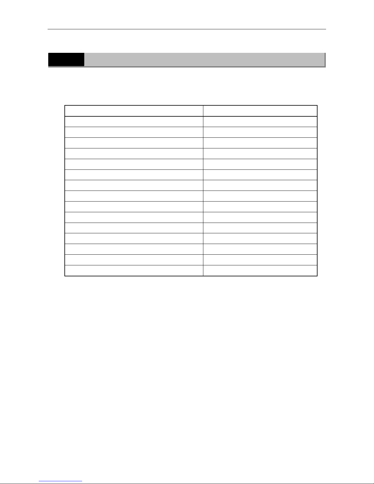
The product names and abbreviations used in this manual are given below.
The manual uses the following abbreviations:
Name of device
Abbreviation
Microscope ECLIPSE 80i 80i
C-ER Eye Level Riser Eye Level Riser
C-TE Ergonomic Binocular Tube Ergonomic Binocular Tube
C-TEP DSC Port for Ergonomic Binocular Tube DSC Port
D-FL Epi-illumination Attachment Epi-illumination Attachment
D-DH Digital Imaging Head M DIH-M
D-CB C-Box C-Box
D-LH Precentered Lamphouse Lamphouse
D-NID6 Intelligent Sextuple DIC Nosepiece Intelligent Nosepiece
C-HS Hand Switch Hand Switch
DS Camera Head DS-5M Camera Head
DS Camera Control Unit DS-L1 DS-L1
DS Camera Cable Camera Cable
Super High-pressure Mercury Lamp Power Supply Unit Mercury Lamp Power Supply Unit
Super High-pressure Mercury Lamphouse Mercury Lamphouse
Page 12

How to use this instruction manual
10
How to use this instruction manual
This instruction manual is composed of two parts, as below:
Manual 1 "Microscopy" describes basic microscope operations that you must follow. Please read
this manual carefully before operating the product.
Manual 2 "Reference" describes the operations of each attachment. Please read an appropriate
section as necessary.
Title Importance Content
Manual 1 Microscopy Must be read Safety precautions
Microscopy, Assembly, Troubleshooting,
Cleaning and maintenance, Specifications
Manual 2 Reference As necessary Detailed operations of attachments
Page 13
Using Microscopy Manual
11
Using Microscopy Manual
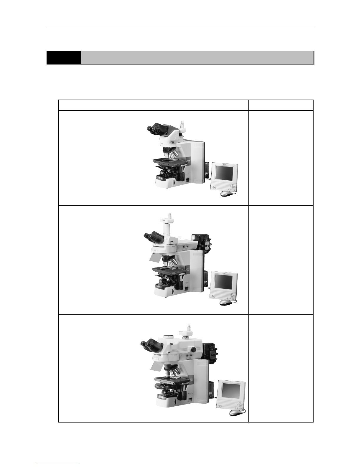
The part names and microscopy procedures are described in three separate sections,
corresponding to specific configurations of 80i and accessory devices. Confirm the combination
of the 80i and accessory devices you are using, then refer to the appropriate section.
Combination Description
Bright-field set
(Eyepiece tube mounted
directly on 80i)
(Camera and monitor are
optional.)
See Chapter 1.
(For operating
procedures and
detailed information on
individual parts, refer
to the separate
Reference manual.)
80i + Epi-illumination
attachment
(Camera and monitor are
optional.)
See Chapter 2.
(For operating
procedures and
detailed information on
individual parts, refer
to the Reference
manual.)
80i + DIH-M
(Camera and monitor are
optional.)
See Chapter 3.
(For operating
procedures and
detailed information on
individual parts, refer
to the Reference
manual.)
Page 14

Contents
12
Contents
Introduction ....................................................................................................... 1
Warning/Caution symbols used in this manual ..................................................................2
Meaning of symbols used on the product ......................................................................... 2
Safety Precautions .............................................................................................. 3
WARNING.................................................................................................... 3
CAUTION..................................................................................................... 5
Notes on handling the product .............................................................................. 7
Abbreviations Used in The Manual ......................................................................... 9
How to use this instruction manual .......................................................................10
Using Microscopy Manual ....................................................................................11
Chapter 1 Part Names and Microscopy Procedures (Bright-Field Set) .........................14
1.1 Names of Main Components ............................................................................... 14
1.2 Names of Parts Used to Make Adjustments........................................................... 15
1.2.1 Right view ................................................................................................... 15
1.2.2 Left view ..................................................................................................... 16
1.2.3 Rear view.................................................................................................... 16
1.2.4 Ergonomic binocular tube with camera attached............................................... 17
1.3 Bright-Field Microscopy ...................................................................................... 18
1.4 Photomicroscopy ............................................................................................... 22
Chapter 2 Part Names and Microscopy Procedures
(With Epi-illumination Attachment Mounted) ..........................................24
2.1 Names of Main Components ............................................................................... 24
2.2 Names of Parts Used to Make Adjustments........................................................... 25
2.2.1 Right view ................................................................................................... 25
2.2.2 Left view ..................................................................................................... 26
2.2.3 Rear view (without accessory device) ............................................................. 26
2.3 Bright-Field Microscopy ...................................................................................... 27
2.4 Epi-fluorescence Microscopy ............................................................................... 31
2.5 Photomicroscopy ............................................................................................... 35
Chapter 3 Part Names and Microscopy Procedures(With DIH-M Mounted))..................37
3.1 Names of Main Components ............................................................................... 37
3.2 Names of Parts Used to Make Adjustments........................................................... 38
3.2.1 Right view ................................................................................................... 38
3.2.2 Left view ..................................................................................................... 39
3.2.3 Rear view (without accessory device) ............................................................. 40
3.3 Bright-Field Microscopy ...................................................................................... 41
3.4 Epi-fluorescence Microscopy ............................................................................... 45
3.5 Photomicroscopy ............................................................................................... 49
Chapter 4 Assembly ........................................................................................... 51
Chapter 5 Replacing Consumables ........................................................................63
5.1 Replacing the lamp............................................................................................ 63
Page 15

Contents
13
Chapter 6 Troubleshooting...................................................................................64
6.1 Optical ............................................................................................................. 64
6.2 Electrical .......................................................................................................... 65
Chapter 7 Cleaning and Maintenance ....................................................................66
7.1 Lens cleaning ................................................................................................... 66
7.2 Cleaning the product ......................................................................................... 66
7.3 Disinfecting the product ..................................................................................... 66
7.4 Storage............................................................................................................ 67
7.5 Periodic Inspections (fee charged)....................................................................... 67
Chapter 8 Specifications......................................................................................68
8.1 Specifications ................................................................................................... 68
Page 16
14
Part Names and Microscopy Procedures
1
(
Bright-Field Set
)
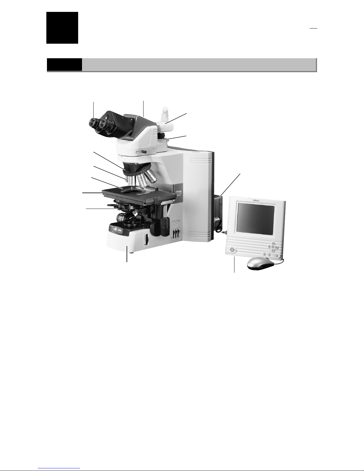
1.1
Names of Main Components
Eyepiece tube
Eyepiece
Objective
Specimen holder
Condenser
Stage
Revolvin
g
nosepiece
DSC port
(Required for image capture)
Camera head
(Required for image capture)
(One example shown in the photo)
Lamphouse
Camera control unit
(Required for image capture)
(One example shown in the photo)
Microscope (main bod
y)
Page 17
Chapter 1 Part Names and Microscopy Procedures (Bright-Field Set)
1.2 Names of Parts Used to Make Adjustments
15
1
1.2
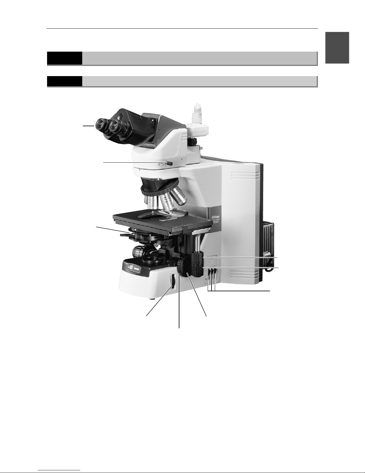
Names of Parts Used to Make Adjustments
1.2.1
Right view
Diopter
ad
j
ustment
ring
Optical path
switching lever
Coarse focus
upper-limit clamp
Aperture diaphragm
lever
Field diaphragm knob
Filter IN/OUT
switches
Fine focus knob
X stage knob
Y stage knob
(
Provided on the left side
in certain products)
Page 18
Chapter 1 Part Names and Microscopy Procedures (Bright-Field Set)
1.2 Names of Parts Used to Make Adjustments
16
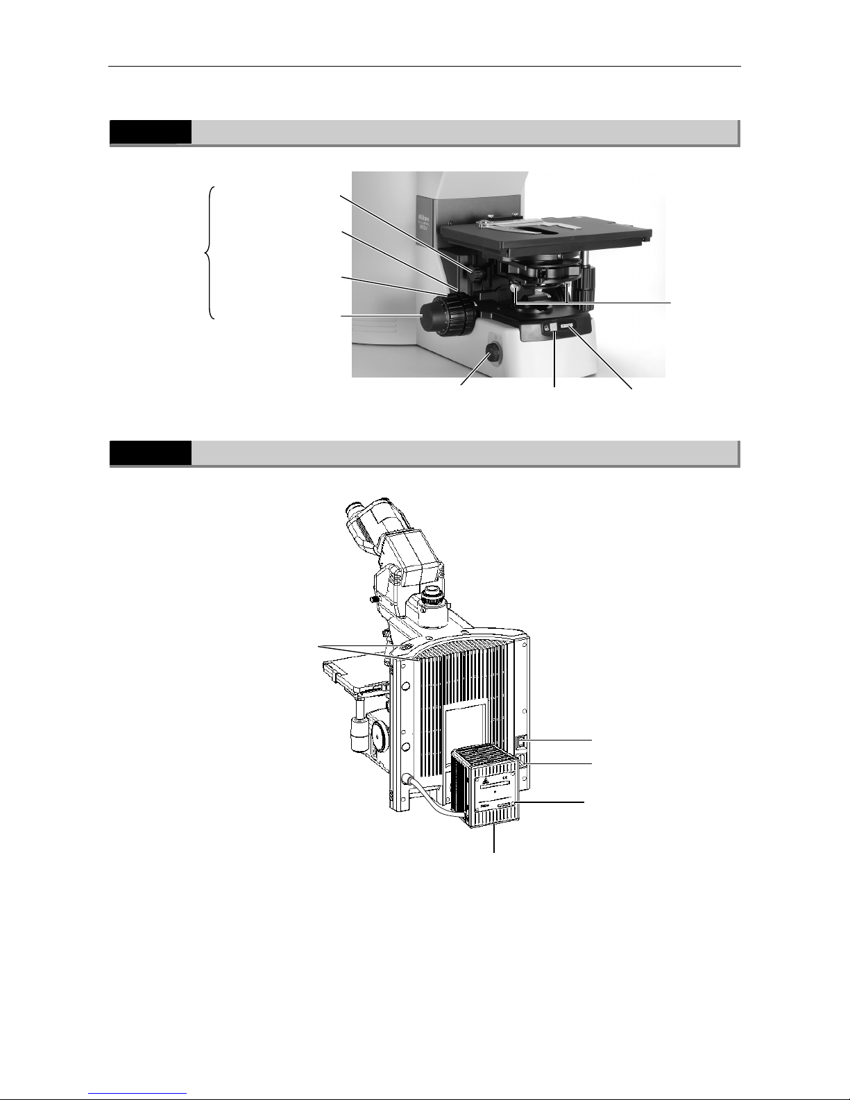
1.2.2
Left view
1.2.3
Rear view
Coarse focus knob
Fine focus knob
Power ON
indicator
Preset switch
Condenser focus knob
Condenser
centering
screw
Coarse focus
torque adjustment
knob
Brightness
control knob
Tool storage
com
p
artment
Power switch
Lamphouse
AC power inlet
Input voltage
indication
(Provided on the
right side in
certain products)
Page 19
Chapter 1 Part Names and Microscopy Procedures (Bright-Field Set)
1.2 Names of Parts Used to Make Adjustments
17
1
1.2.4
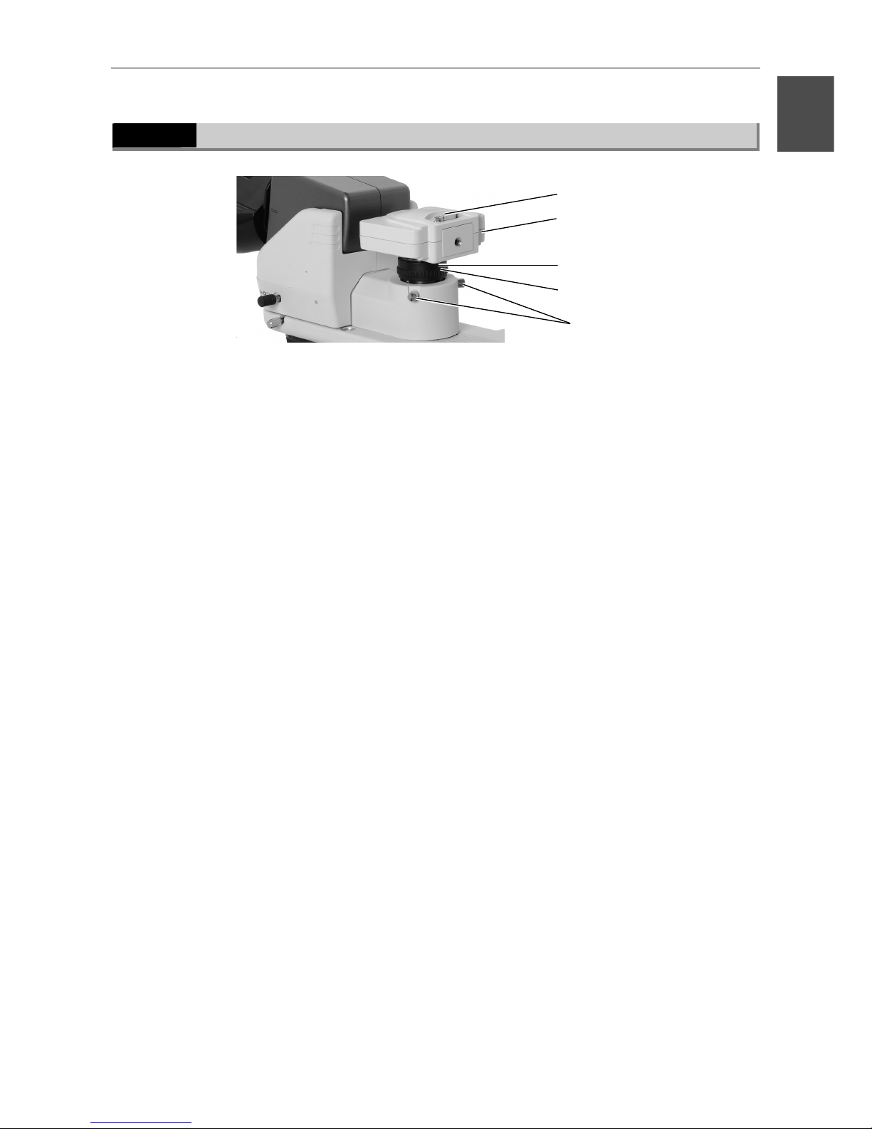
Ergonomic binocular tube with camera attached
Camera centering screws
Camera fine focus
adjustment screw
C mount
Camera head
Camera cable connector
Page 20
Chapter 1 Part Names and Microscopy Procedures (Bright-Field Set)
1.3 Bright-Field Microscopy
18
1.3
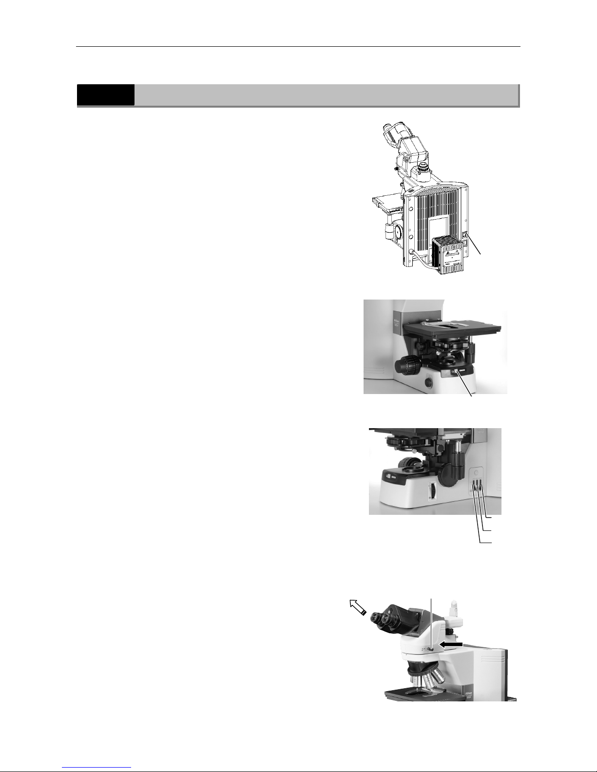
Bright-Field Microscopy
1
Turn on power.
2
Press the preset switch.
3
Move the ND8, ND32, and NCB11
filters into the optical path.
4
Push in the optical path
switching lever to direct the full
optical path toward the
binocular section.
Press the power
switch to the "|"
position.
Press the preset switch.
The full optical
path directed
toward the
binocular
section
Push in the optical
path-switching lever.
ND8
ND32
NCB11
Page 21
Chapter 1 Part Names and Microscopy Procedures (Bright-Field Set)
1.3 Bright-Field Microscopy
19
1
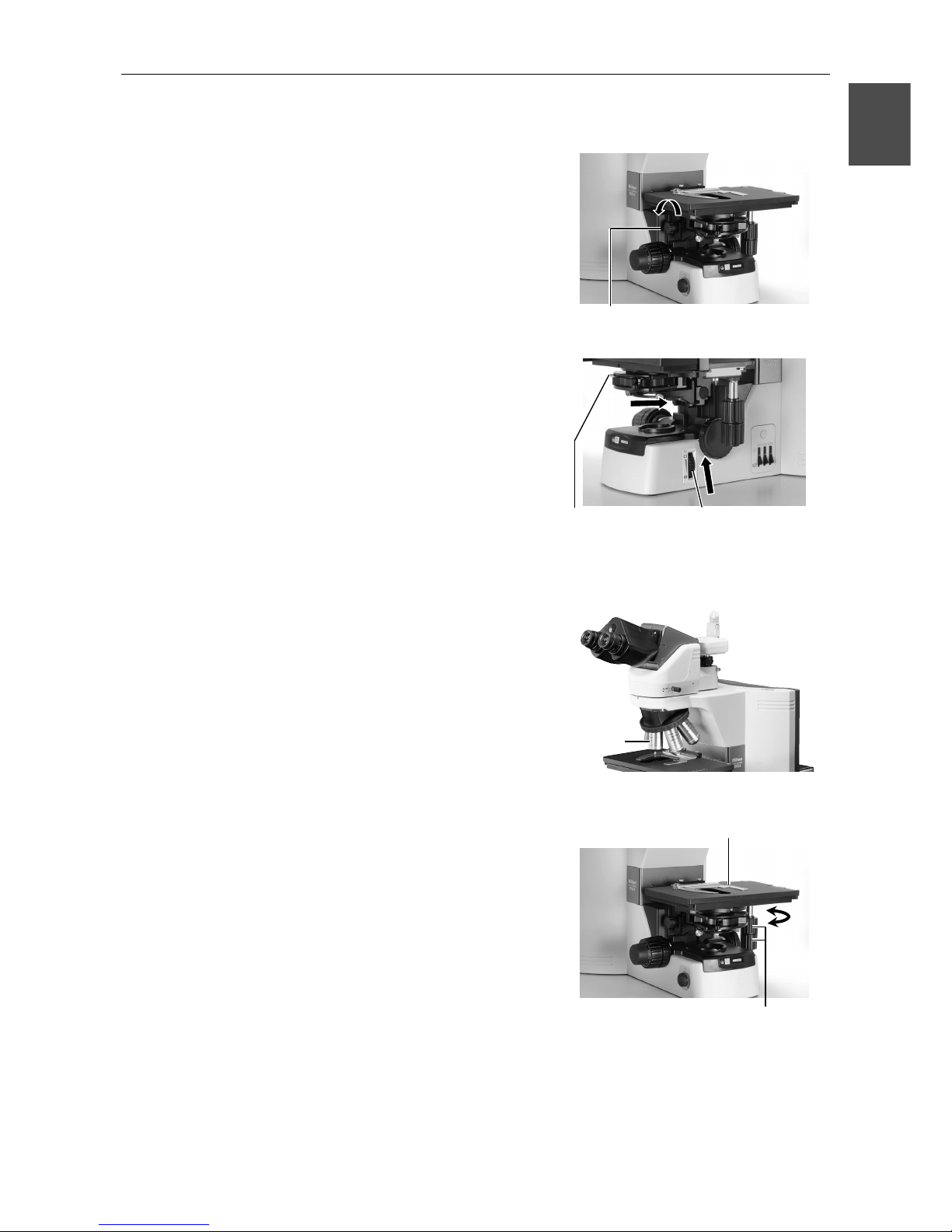
5
Raise the condenser to the
uppermost position.
6
Fully open the field diaphragm
and aperture diaphragm.
(When using the 1-100x condenser, move the top
lens into the optical path.)
7
Set the 10x objective into the
optical path.
8
Set a specimen and move the
portion to be viewed into the
optical path.
Set a specimen and secure in
place using the specimen holder.
Move the portion to be viewed into the
optical path using the XY stage knobs.
Fully open the
aperture diaphragm
using the aperture
diaphragm lever.
Fully open the field
diaphragm using the
field diaphragm knob.
Raise the condenser using the
condenser focus knob.
Select
the 10x
objective.
Page 22
Chapter 1 Part Names and Microscopy Procedures (Bright-Field Set)
1.3 Bright-Field Microscopy
20
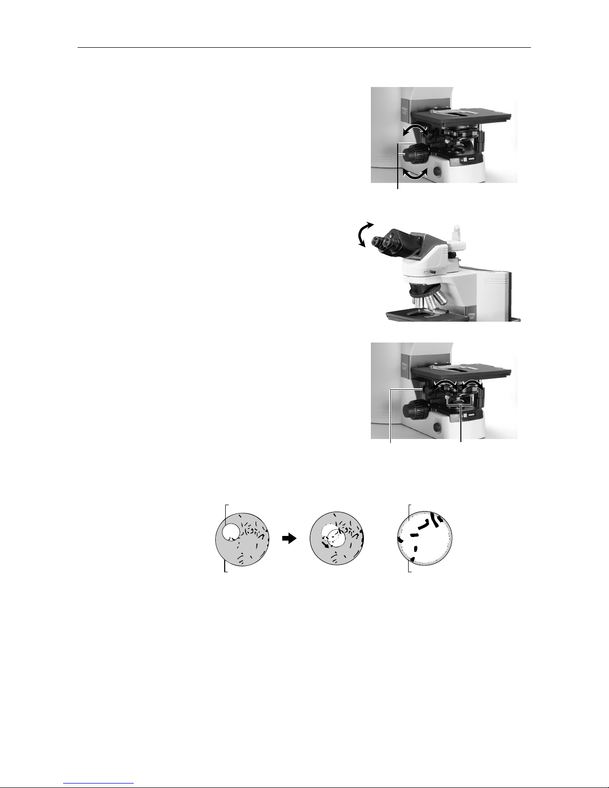
9
Focus on the specimen.
10
Adjust the diopter and the
interpupillary distance.
Refer to "8. Diopter Adjustment" and "9.
Interpupillary Distance Adjustment" in the separate
Reference manual.
11
Focus and center the condenser.
Refer to "11. Adjustment of Condenser Position" in
the separate Reference manual.
Focus on the specimen using
the coarse and fine focus knobs.
Center the condenser
using the condenser
centering screws.
Focus the condenser
using the condenser
focus knob.
Field diaphragm
Eyepiece field
of view
Field diaphragm
Eyepiece field
of view
Page 23
Chapter 1 Part Names and Microscopy Procedures (Bright-Field Set)
1.3 Bright-Field Microscopy
21
1
12
Switch to the desired objective
and view the specimen.
Adjust the field diaphragm and
aperture diaphragm each time
you change objectives.
ield diaphragm:
Set slightly narrower than the margins of
the field of view.
erture diaphragm:
70% to 80% of the maximum numerical
aperture (N.A.) of the objective
13
Turn off power after completing
observations.
Select the
desired objective.
Press the power
switch to the "◯"
position.
Aperture diaphragm
knob
Field diaphragm knob
Page 24
Chapter 1 Part Names and Microscopy Procedures (Bright-Field Set)
1.4 Photomicroscopy
22
1.4
Photomicroscopy
For detailed explanations of the camera, photomicroscopic software, and PC, refer to the
operating manuals provided with the respective products. The following instructions assume a
DS-5M digital camera and DS-L1 camera control unit.
1
Adjust the microscope for proper image observation.
See the directions given earlier in "1. Bright-Field Microscopy."
2
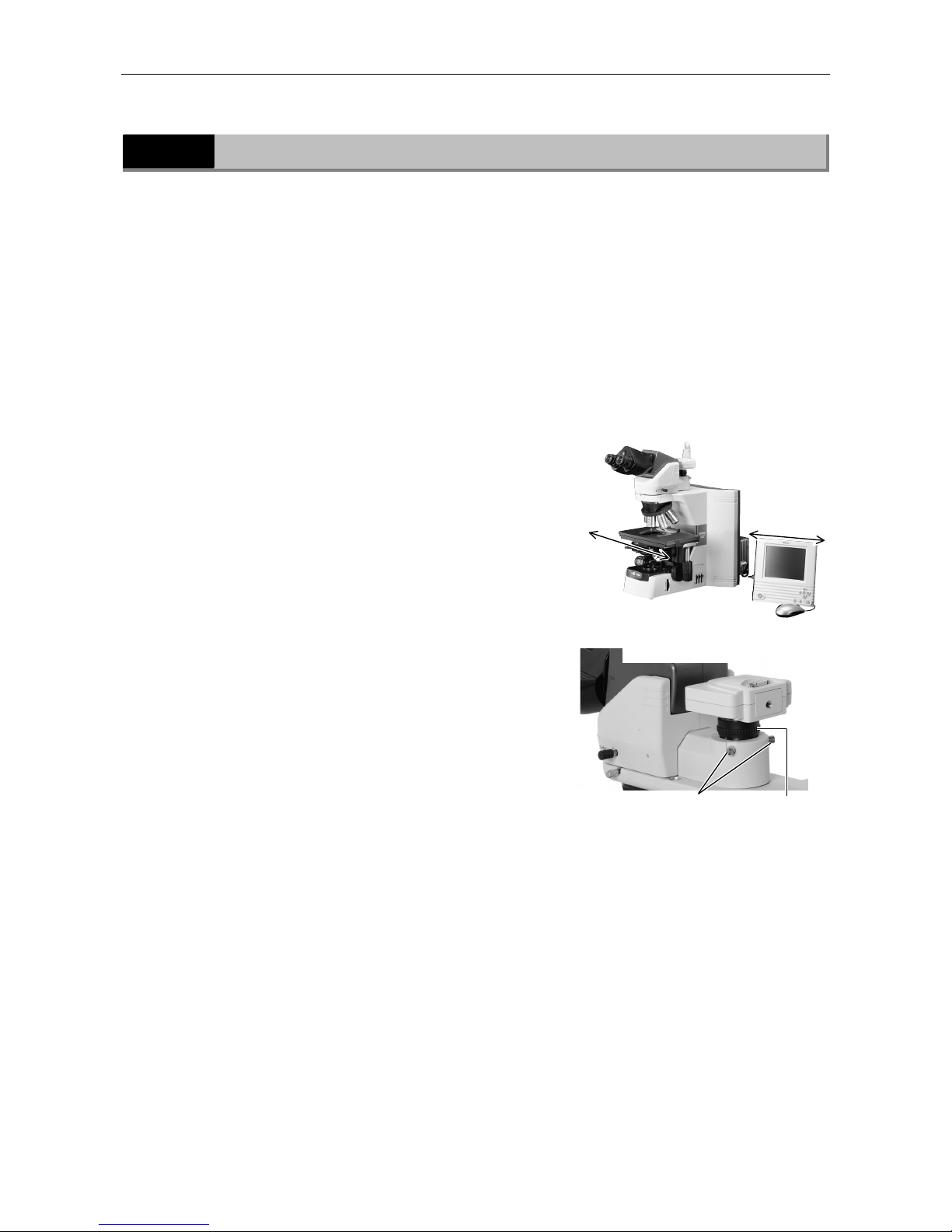
Adjust the camera head mounting position until the image is
displayed properly.
(1) Adjustment based on stage motion direction
Loosen the camera centering screws on the C
mount and adjust the camera position so that
moving the stage forward-backward or
left-right moves the image on the monitor in
the same direction. After making the
appropriate adjustments, tighten the screws
firmly.
(2) Focus adjustment
If the image viewed through the eyepiece
appears to be in focus but the image on the
monitor is out of focus, turn the camera fine
focus adjustment screw on the C mount until
the image on the monitor is in focus. (Use a
low-magnification lens to make this
adjustment.)
Note that such out of focus situations can also
indicate incorrect diopter adjustment. Make
sure you have made diopter adjustments
before adjusting camera focus. (Refer to the
separate Reference manual.)
3
Make camera settings.
For a detailed discussion of this topic, refer to the operating manual provided with the camera.
When using the DS-L1, you must choose and enter at least the following information:
• Folder for data storage.
• Name of file to be saved. (You can select "Auto.")
• File format and file size.
• Date and destination of data
Camera centeringscrews
Camera fine focus
adjustment screw
(A)
(B)Adj
usting (A) and (B)
Page 25

Chapter 1 Part Names and Microscopy Procedures (Bright-Field Set)
1.4 Photomicroscopy
23
1
4
Select the camera scene mode suitable for the microscopy
method.
5
Set the camera white balance.
To adjust white balance, press the WB button while capturing an image of a clear section of a
specimen slide. (For fluorescent photomicrography, adjust white balance under normal lighting
conditions before shooting.)
6
Capture and save images.
Focus on the specimen.
Refocus.
Adjust image brightness using the camera exposure compensation function.
Check the image using the Freeze button.
If the image is acceptable, press the CAPT. button to save the image.
(The operating procedure differs if DF/FL scene mode is selected. For a detailed discussion of
this topic, refer to the operating manual provided with the camera.)
Page 26
24
Part Names and Microscopy Procedures
2
(
With Epi-illumination Attachment Mounted
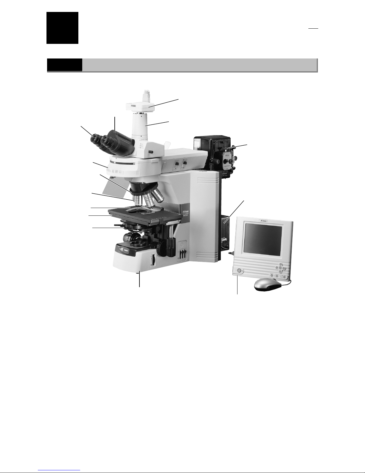
)
2.1
Names of Main Components
Eyepiece tube
Eyepiece
Objective
Specimen holder
Condenser
Stage
Revolving nosepiece
Epi-illumination lamphouse
(The Epi-illumination
attachment uses a mercury,
xenon, or high-intensity
halogen lamp as its light
source. It requires a separate
p
ower supply unit. Before using
the lam
p
house, be sure to read
the lamp operating manual.)
Camera head
(Required for image capture)
(One example shown in the photo)
Lamphouse
Camera control unit
(Required for image capture)
Microscope (main bod
y)
Photographic vertical tube adapter
(Required for image capture)
Epi-illumination
attachmen
t
Page 27
Chapter 2 Part Names and Microscopy Procedures (With Epi-illumination Attachment Mounted)
2.2 Names of Parts Used to Make Adjustments
25
2
2.2
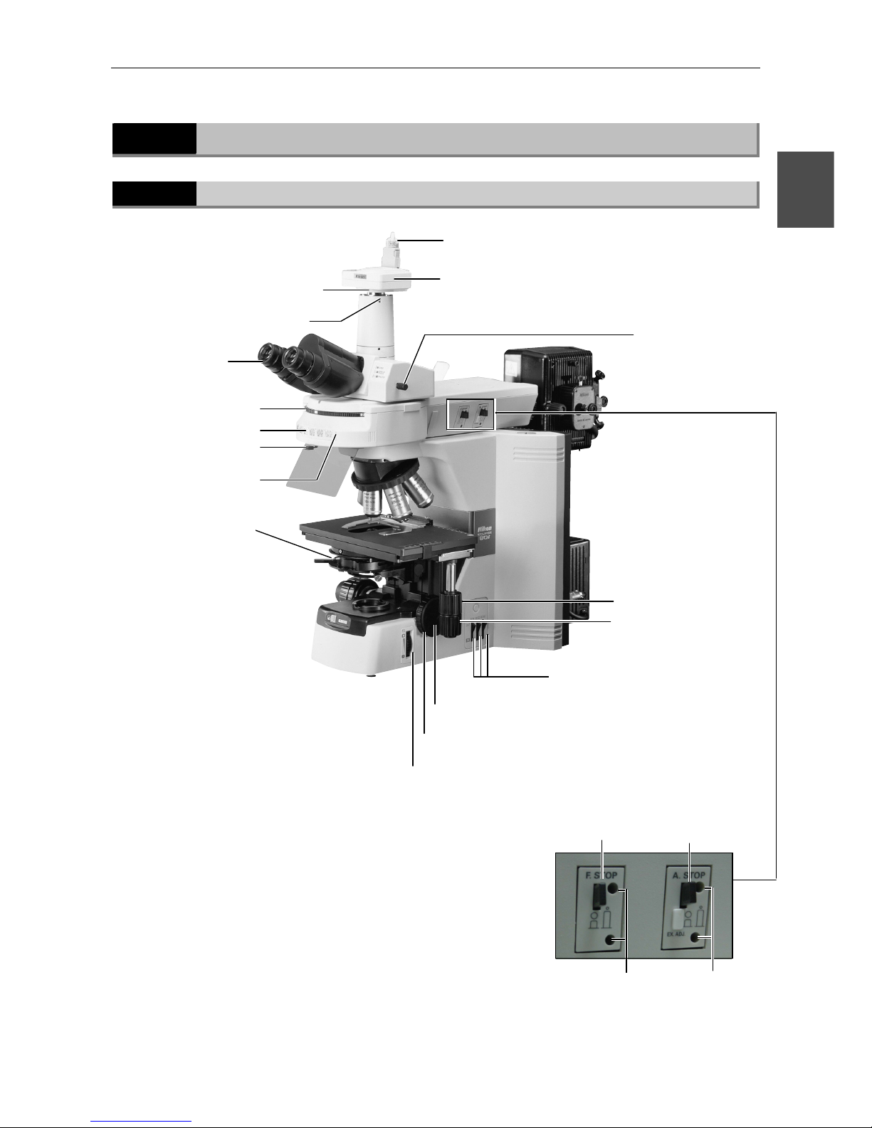
Names of Parts Used to Make Adjustments
2.2.1
Right view
Diopter adjustment
ring
Optical path
switching lever
Coarse focus upper-limit clam
p
Aperture diaphragm
leve
r
Field diaphragm knob
Filter IN/OUT switch
X ステージハンド
X stage knob
Camera head
Camera cable
C mount adapter
Excitation method
switchover turret
Excitation ID tag pocket
Shutter open/close
leve
r
Fine focus knob
Filter cube mounting
section (inside)
Field diaphragm
open/close lever (for
Epi-fluorescent light)
Aperture diaphragm
open/close lever (for
Epi-fluorescent light)
Field diaphragm
centering holes
Aperture diaphragm
centering holes
Y stage knob
(Provided on the left side
in certain products)
C mount ada
p
ter retaining screw
Page 28
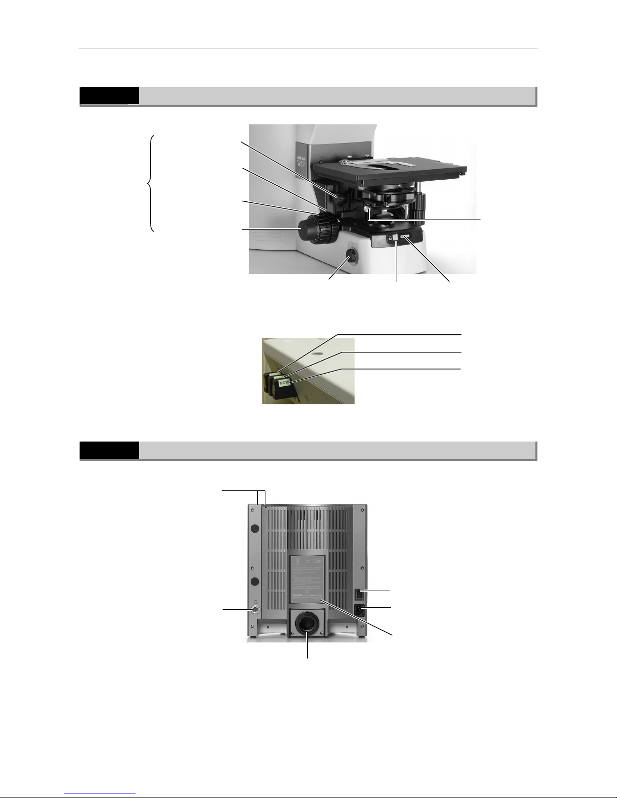
Chapter 2 Part Names and Microscopy Procedures (With Epi-illumination Attachment Mounted)
2.2 Names of Parts Used to Make Adjustments
26
2.2.2
Left view
2.2.3
Rear view (without accessory device)
Coarse focus
knob
Fine focus knob
Power ON indicator
Preset switch
Condenser focus knob
Condenser
centering
screw
Coarse focus torque
adjustment knob
Brightness control knob
Tool storage compartment
Power switch
AC inlet
Input voltage indication
Lamphouse mounting section
Lamphouse
connector port
ND4 filter slider
ND16 filter slider
ND8 filter slider
(Provided on
the right side
in certain
products)
Left side the Epi-illumination attachment
Page 29
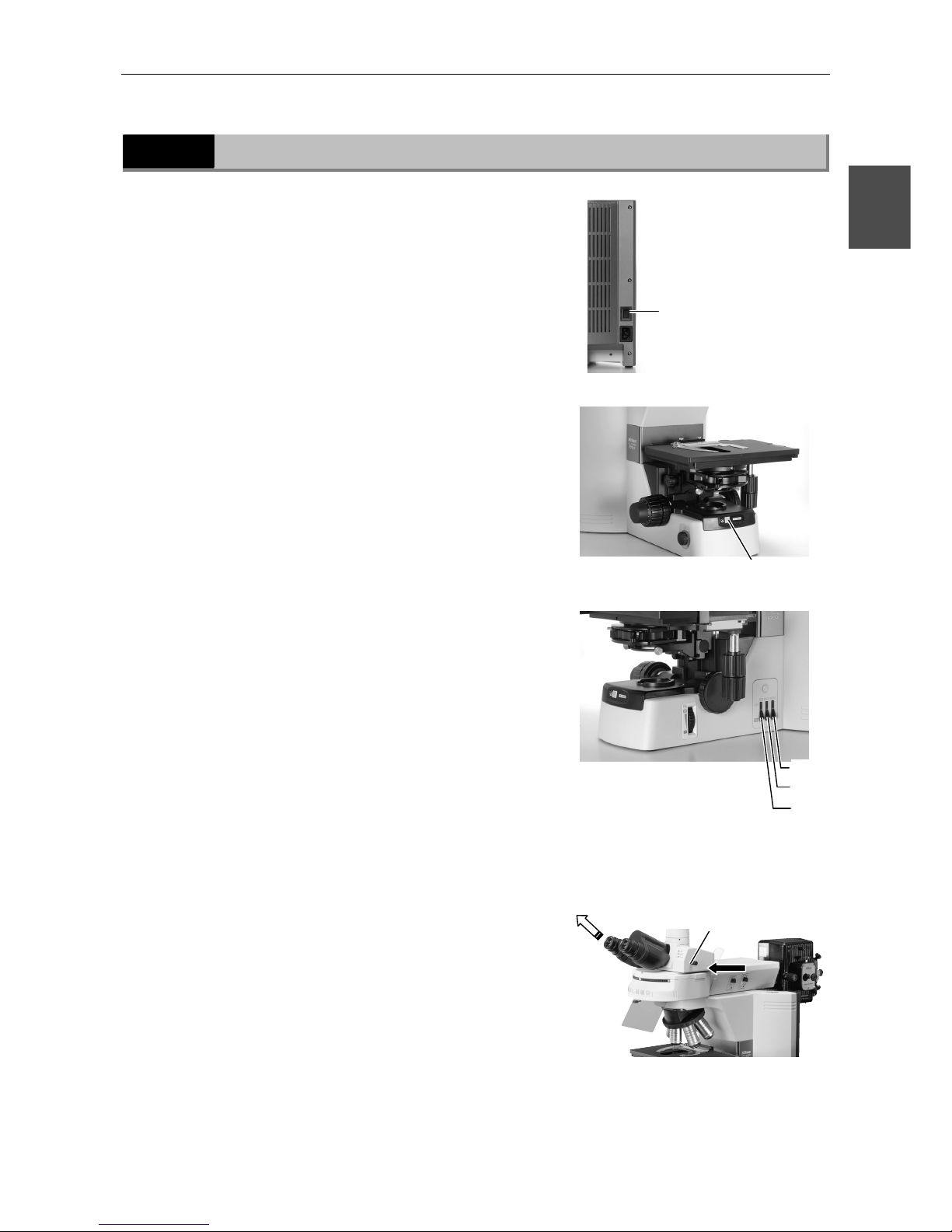
Chapter 2 Part Names and Microscopy Procedures (With Epi-illumination Attachment Mounted)
2.3 Bright-Field Microscopy
27
2
2.3
Bright-Field Microscopy
1
Turn on power.
2
Press the preset switch.
3
Move the ND8, ND32, and
NCB11 filters into the optical
path.
4
Push the optical path-switching
lever to direct the full optical
path toward the binocular
section.
Press the power switch to
the "|" position.
Press the preset switch.
ND8
ND32
NCB11
The full optical
path directed
toward binocular
section
Push in the optical
path-switching lever.
Page 30
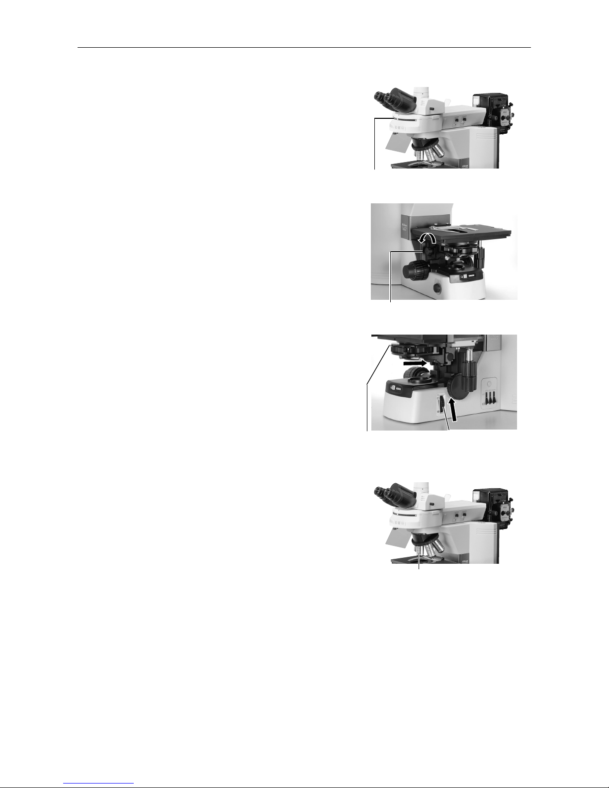
Chapter 2 Part Names and Microscopy Procedures (With Epi-illumination Attachment Mounted)
2.3 Bright-Field Microscopy
28
5
Rotate the excitation method
switchover turret to set it at
position where no filter cube is
installed.
6
Raise the condenser to the
uppermost position.
7
Fully open the field diaphragm
and aperture diaphragm.
(When using the 1-100x condenser, move the top
lens into the optical path.)
8
Set the 10x objective into the
optical path.
Fully open the
aperture diaphragm
using the aperture
diaphragm lever.
Fully open the field
diaphragm using the
field diaphragm knob.
Select the 10x
objective.
Raise the condenser using the
condenser focus knob.
Rotate the excitation method
switchover turret.
Page 31
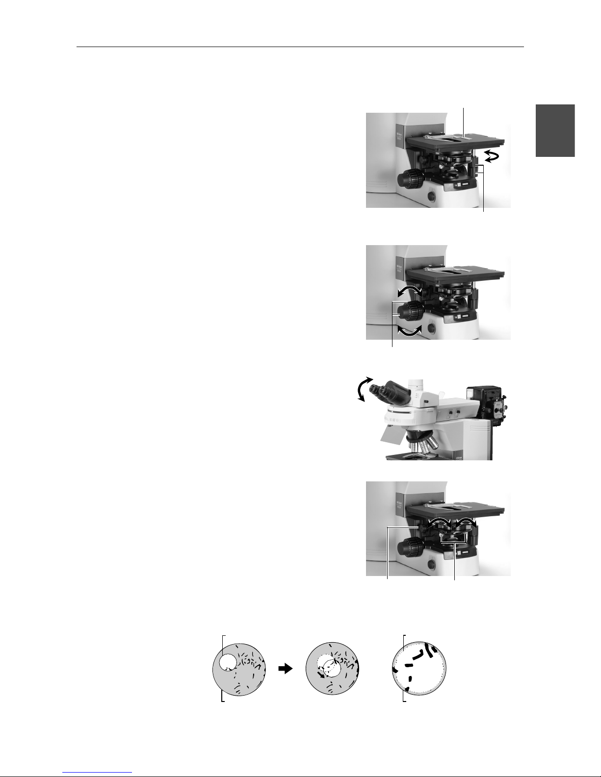
Chapter 2 Part Names and Microscopy Procedures (With Epi-illumination Attachment Mounted)
2.3 Bright-Field Microscopy
29
2
9
Set a specimen and move the
portion to be viewed into the
optical path.
10
Focus on the specimen.
11
Adjust the diopter and the
interpupillary distance.
Refer to "8. Diopter Adjustment" and "9.
Interpupillary Distance Adjustment" in the separate
Reference manual.
12
Focus and center the condenser.
Refer to "11. Adjustment of Condenser Position" in
the separate Reference manual.
Set a specimen and secure in
place using the specimen holder.
Focus on the specimen using
the coarse and fine focus knobs.
Center the condenser
using the condenser
centering screws.
Focus the condenser
using the condenser
focus knob.
Field diaphragm
Eyepiece field of view
Move the portion to be viewed into the
optical path using the XY stage knobs.
Field diaphragm
Eyepiece field of view
Page 32
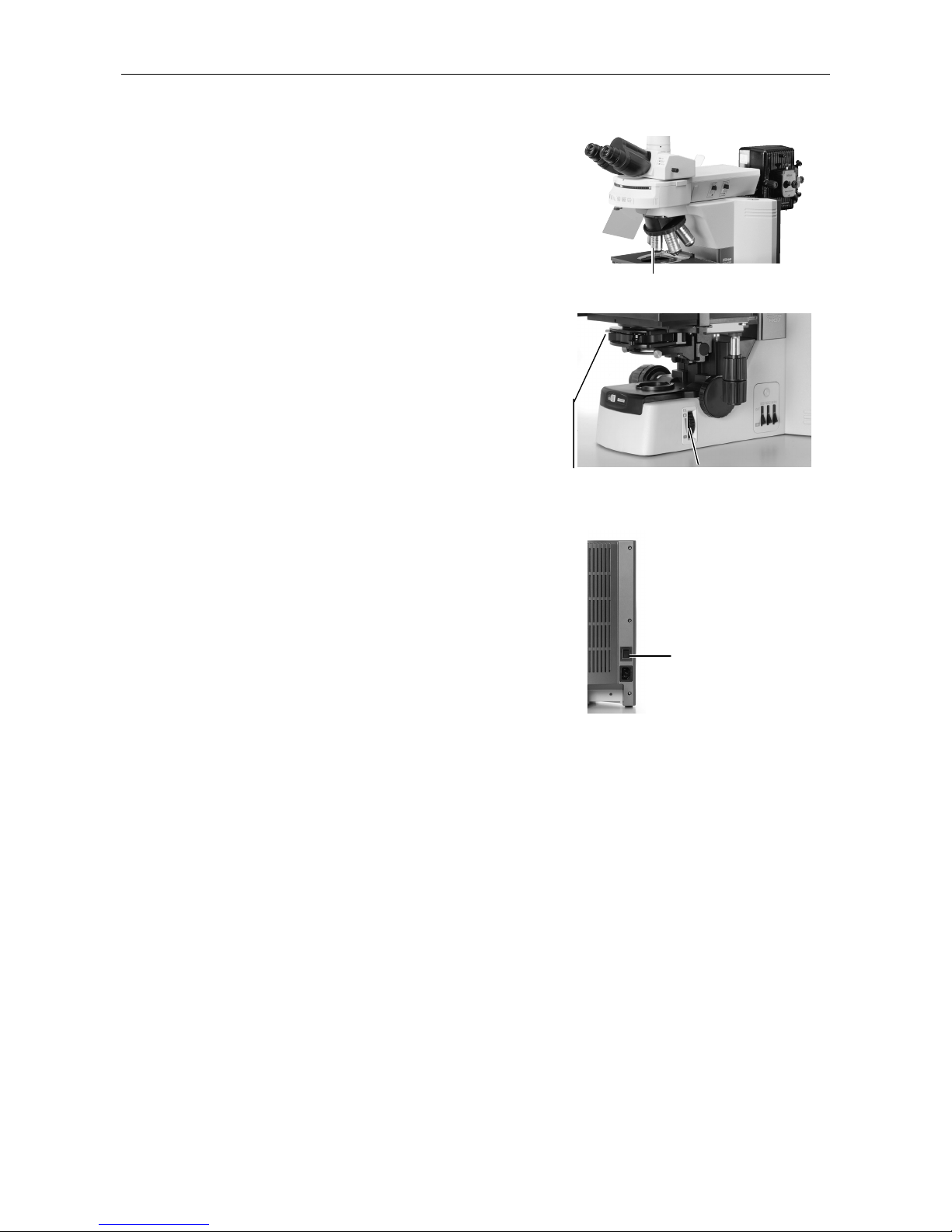
Chapter 2 Part Names and Microscopy Procedures (With Epi-illumination Attachment Mounted)
2.3 Bright-Field Microscopy
30
13
Switch to the desired objective
and view the specimen.
Adjust the field diaphragm and
aperture diaphragm each time
you change objectives.
ield diaphragm:
Set slightly narrower than the margins of
the field of view.
erture diaphragm:
70% to 80% of the maximum numerical
aperture (N.A.) of the objective
14
Turn off power after completing
observations.
Select the desired objective.
Press the power switch
to the "◯" position.
Aperture diaphragm
knob
Field diaphragm knob
Page 33
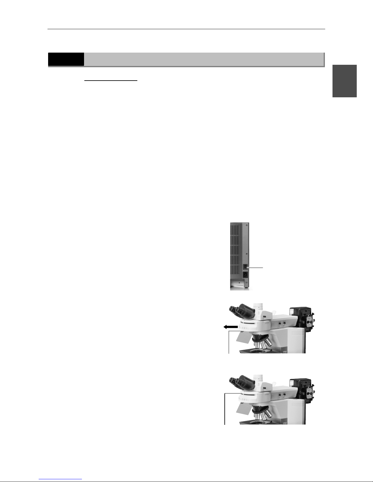
Chapter 2 Part Names and Microscopy Procedures (With Epi-illumination Attachment Mounted)
2.4 Epi-fluorescence Microscopy
31
2
2.4
Epi-fluorescence Microscopy
Before microscopy...
• Check the cumulative operating hours of the lamp in the Epi-illumination
attachment. Replace the lamp if its cumulative operating hours exceed the
recommended maximum service life.
• Use non-fluorescent slide glass.
• Use non-fluorescent immersion oil.
• To keep specimen colors from fading, keep the shutter closed when not
performing microscopy.
1
Perform steps 1 through 11 in "2.3 Bright-Field
Microscopy."
2
Lower the condenser, or remove the condenser and mount
the shielding tube in its place.
3
Turn off the microscope power
switch.
4
Close the shutter and block the
Epi-illumination light.
5
Move the filter cube for the
excitation method to be used
into the optical path.
Press the power switch
to the "◯" position.
Close the shutter.
Select a cube using the excitation
method switchover turret.
Page 34
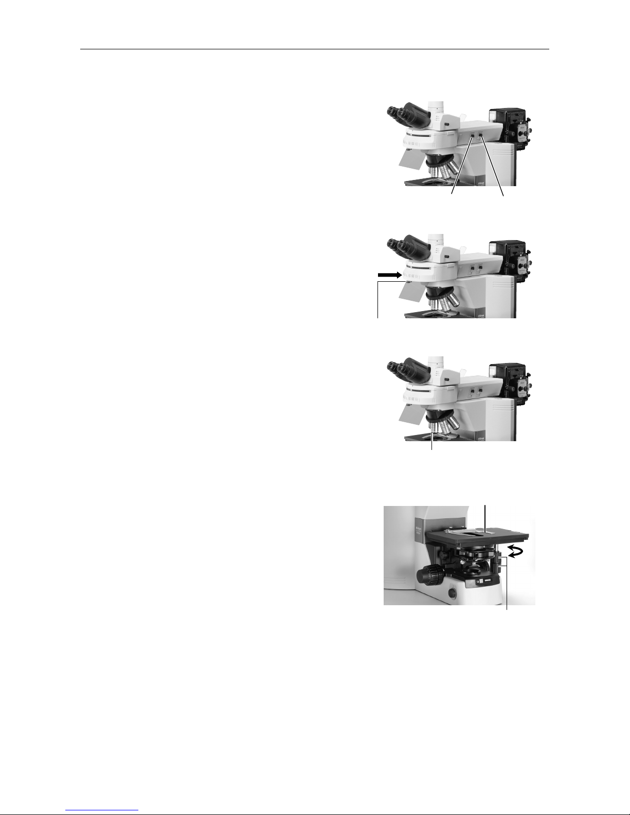
Chapter 2 Part Names and Microscopy Procedures (With Epi-illumination Attachment Mounted)
2.4 Epi-fluorescence Microscopy
32
6
Fully open the field diaphragm
and aperture diaphragm of the
Epi-illumination attachment.
7
Switch on power for the light
source of the Epi-illumination
attachment, then open the
shutter and center the lamp.
(Refer to the operating manual
for the light source.)
8
Set the 10x objective into the
optical path.
9
Set a specimen and move the
portion to be viewed into the
optical path.
Fully open the field
diaphragm.
Select the 10x objective.
Set a specimen and secure in place
using the specimen holder.
Move the portion to be viewed into the
optical path using the XY stage knobs.
Open the shutter.
Fully open the
aperture diaphragm.
Page 35
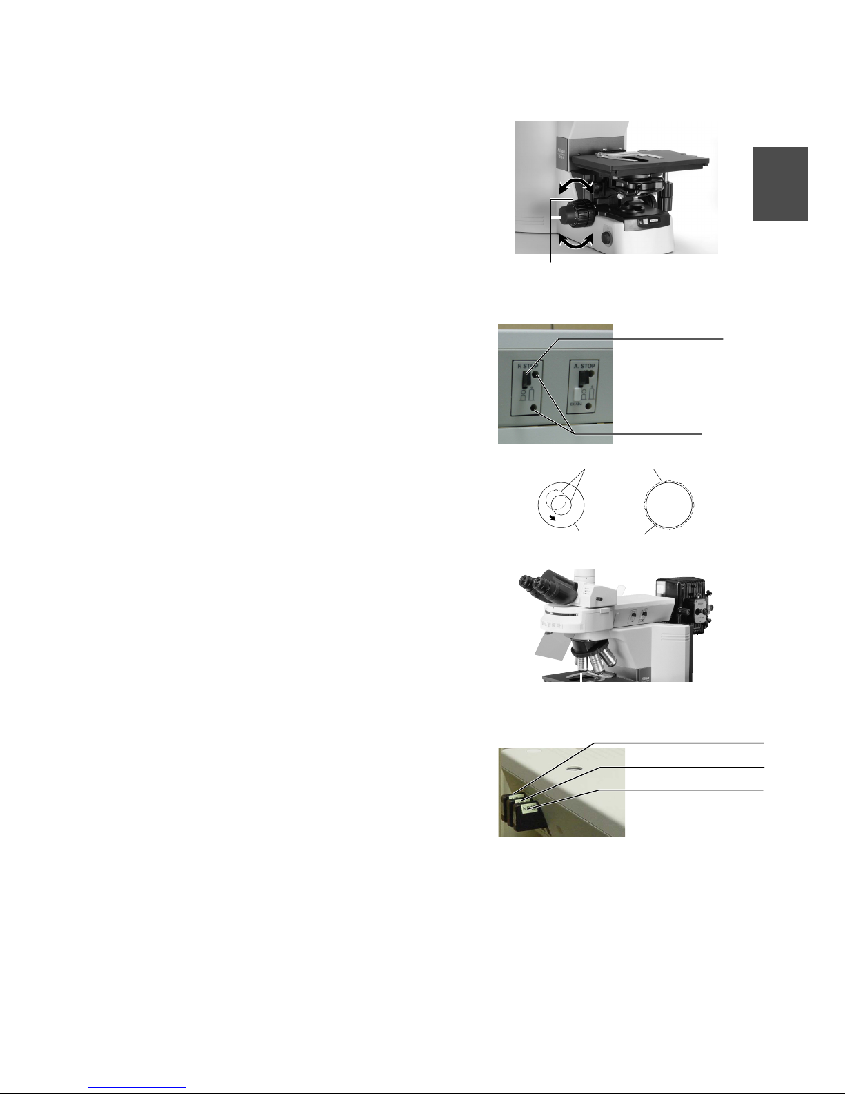
Chapter 2 Part Names and Microscopy Procedures (With Epi-illumination Attachment Mounted)
2.4 Epi-fluorescence Microscopy
33
2
10
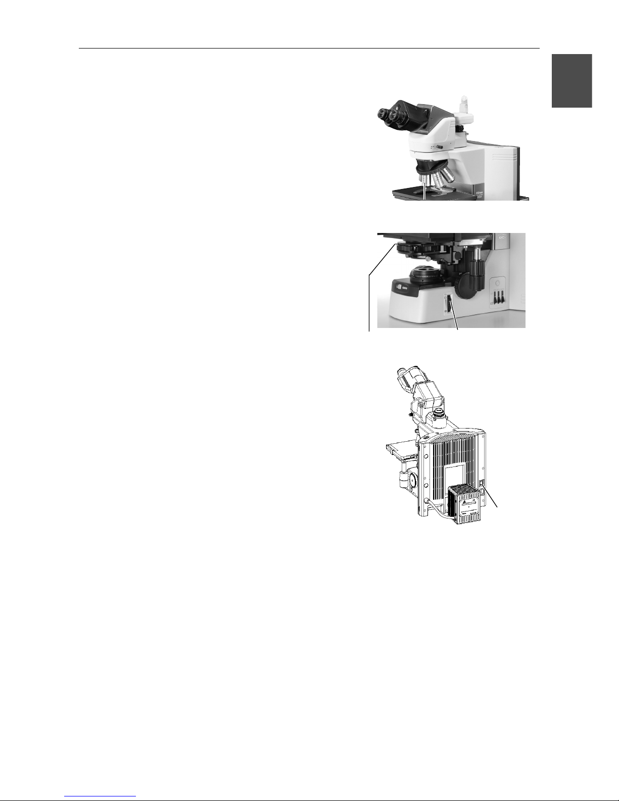
Focus on the specimen.
11
Center the field diaphragm of the
Epi-illumination attachment.
Refer to "4. Epi-fluorescent Field Diaphragm" in
"17. Fluorescence Observation" of the separate
Reference manual.
12
Switch to the desired objective
and view the specimen.
• Use the ND filters for the fluorescence
attachment to adjust brightness.
• Adjust the field diaphragm so that it extends
slightly beyond the field of view.
• The image brightness can be adjusted with
the aperture diaphragm. Complete centering
before using the aperture diaphragm.
• When using oil immersion objectives, apply
immersion oil between the specimen and the
objective.
Focus on the specimen using
the coarse and fine focus knobs.
Field
diaphragm
image
Field diaphragm
open/close lever
Field diaphragm
centering screw holes
Eyepiece
field of view
ND4 filter slider
ND16 filter slider
ND8 filter slider
Select the desired
objective.
Page 36
Chapter 2 Part Names and Microscopy Procedures (With Epi-illumination Attachment Mounted)
2.4 Epi-fluorescence Microscopy
34
13
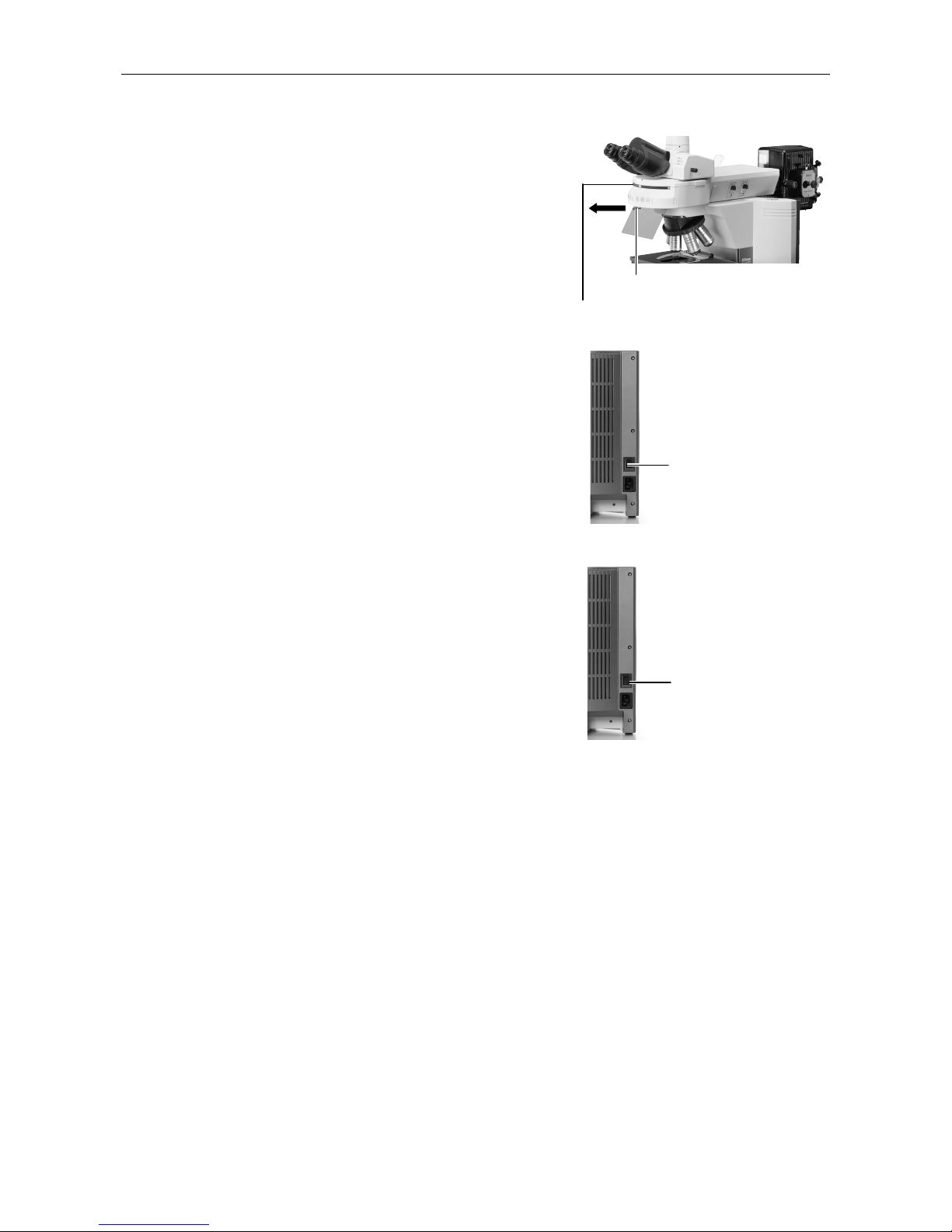
To return to bright-field
microscopy
• Close the shutter of the Epi-illumination
attachment and block the epifluorescent light.
• Rotate the excitation method switchover turret
to move the position where no fluorescent
cube is installed into the optical path.
• If the condenser is not mounted, install the
condenser, then focus and center the
condenser. (Refer to step 12 of bright-field
microscopy.)
• Turn on the microscope power switch to turn
on the diascopic light source.
14
Turn off all power switches after
completing observations.
Press the power switch
to the "◯" position.
Close the shutter.
Use the excitation method switchover
turret to change cubes.
Press the switch to the
"|" position.
Page 37
Chapter 2 Part Names and Microscopy Procedures (With Epi-illumination Attachment Mounted)
2.5 Photomicroscopy
35
2
2.5
Photomicroscopy
For detailed discussions of the camera, photomicroscopic software, and PC, refer to the
operating manuals provided with the respective products. The following instructions assume a
DS-5M digital camera and DS-L1 camera control unit.
1
Adjust the microscope for proper image observation.
See the directions given in previous "1. Bright-Field Microscopy" or "2. Epi-fluorescence
Microscopy."
2
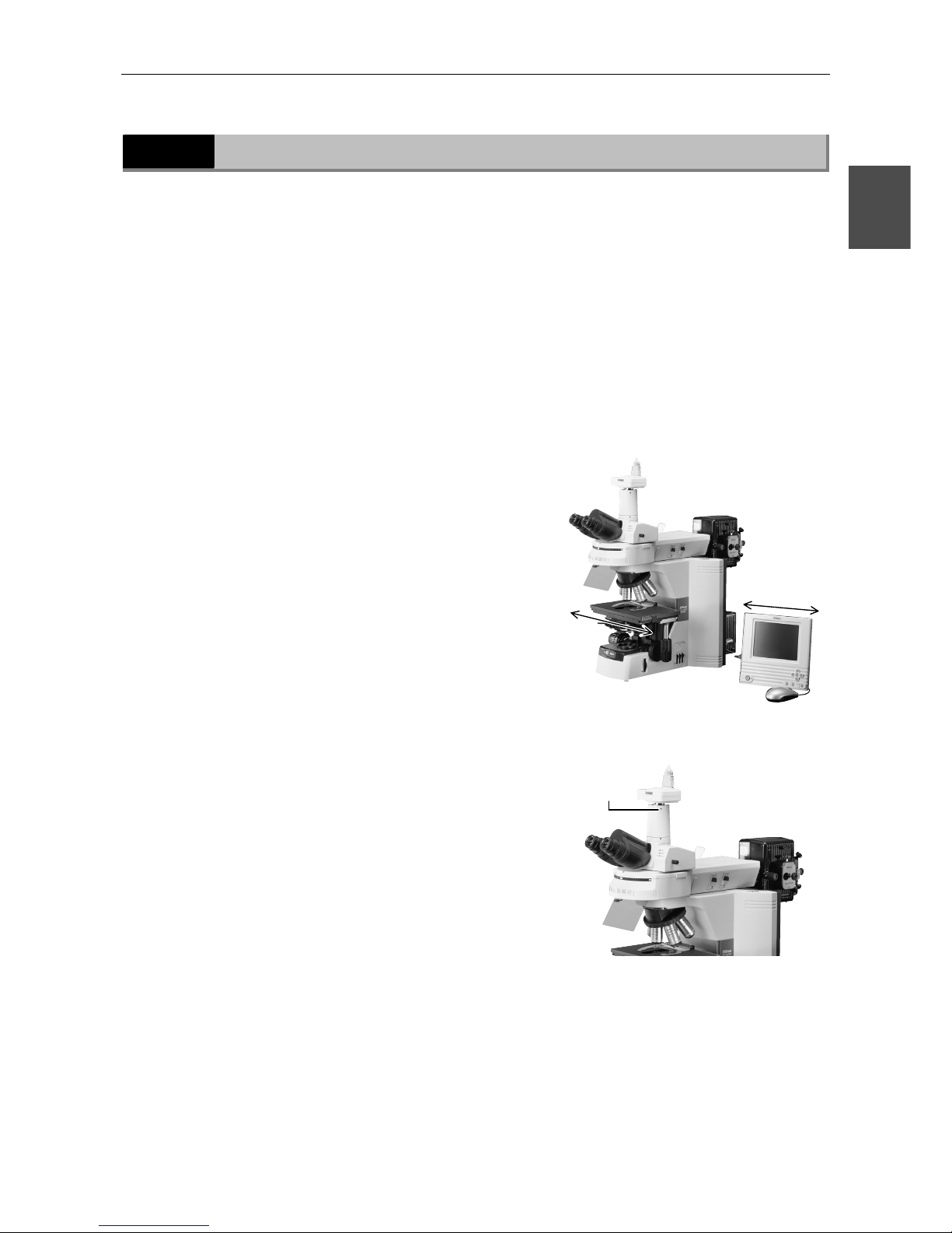
Adjust the camera head mounting position until the image is
displayed properly.
(1) Adjustment based on stage motion
directionLoosen the C-mount adapter
retaining screw and adjust the camera
position so that moving the stage
forward-backward or left-right moves the
image on the monitor in the same direction.
After making the appropriate adjustments,
tighten the screw firmly.
C-mount
adapter
retaining
screw
(A)
(B)Adj
usting (A) and (B)
Page 38

Chapter 2 Part Names and Microscopy Procedures (With Epi-illumination Attachment Mounted)
2.5 Photomicroscopy
36
3
Make camera settings.
For a detailed discussion of this topic, refer to the operating manual provided with the camera.
When using the DS-L1, you must choose and enter at least the following information:
• Folder for data storage.
• Name of file to be saved. (You can select "Auto.")
• File format and file size.
• Date and destination of data
4
Select the camera scene mode suitable for the microscopy
method.
5
Set the camera white balance.
To adjust white balance, press the WB button while capturing an image of a clear section of a
specimen slide. (For fluorescent photomicrography, adjust white balance under normal lighting
conditions before shooting.)
6
Capture and save images.
Focus on the specimen.
Refocus.
Adjust image brightness using the camera exposure compensation function.
Check the image using the Freeze button.
If the image is acceptable, press the CAPT. button to save the image.
(The operating procedure differs if DF/FL scene mode is selected. For a detailed discussion of
this topic, refer to the operating manual provided with the camera.)
Page 39
37
Part Names and Microscopy Procedures
3
(
With DIH-M Mounted
)
3
3.1
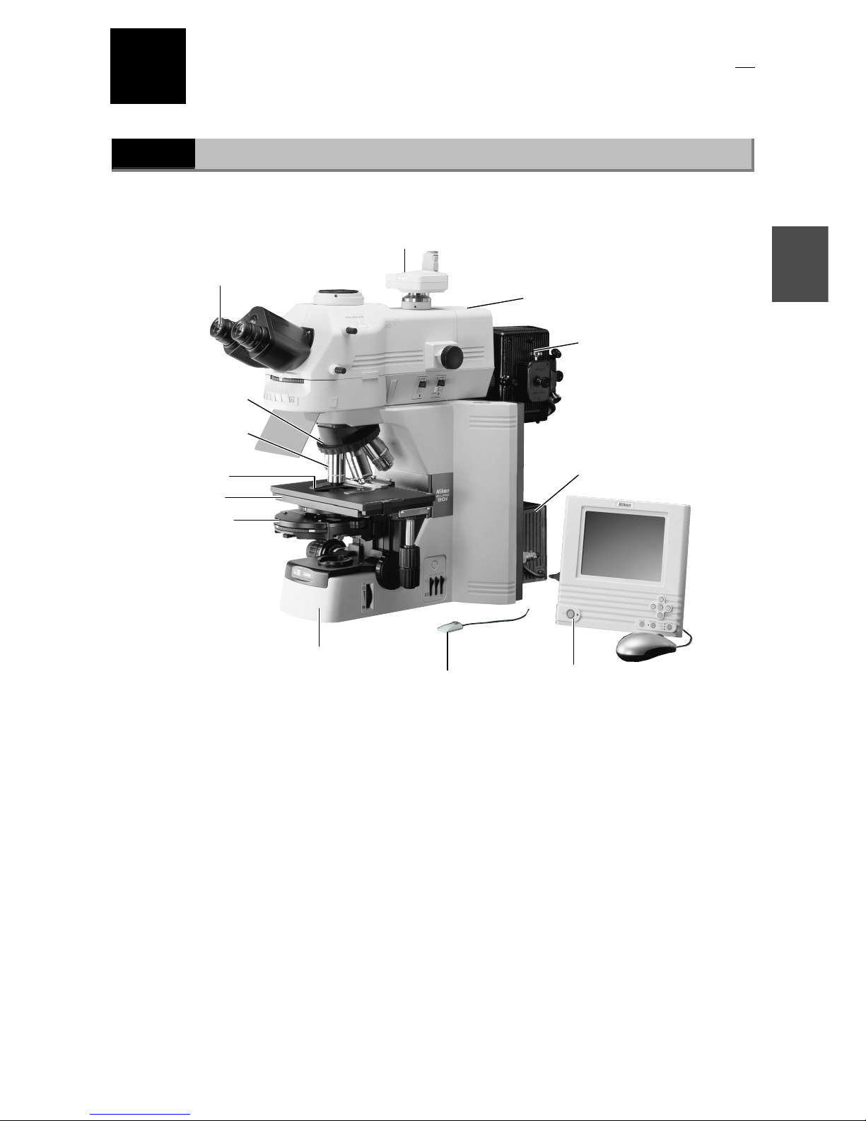
Names of Main Components
Eyepiece
Objective
Specimen holder
Condenser
Stage
Revolving nosepiece
Epi-illumination lamphouse
(The Epi-illumination attachment
uses a mercury, xenon, or
high-intensity halogen lamp as
its light source. It requires a
separate power supply unit.
Before using the lamphouse, be
sure to read the lamp operating
manual.)
Camera head
(Required for image capture)
(One example shown in the photo)
Lamphouse
Camera control unit
(Required for image capture)
(One example shown in the photo)
Microscope
(main body)
DIH-M
Shutter open/close
hand switch for
Epi-fluorescent light
Page 40
Chapter 3 Part Names and Microscopy Procedures(With DIH-M Mounted)
3.2 Names of Parts Used to Make Adjustments
38
3.2
Names of Parts Used to Make Adjustments
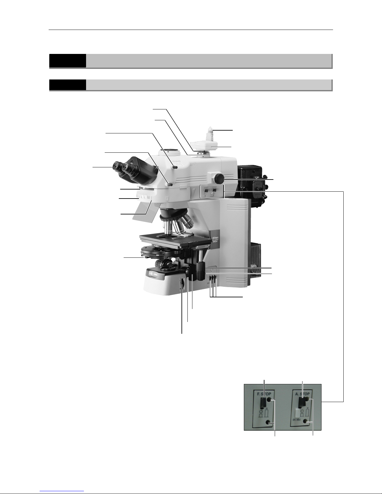
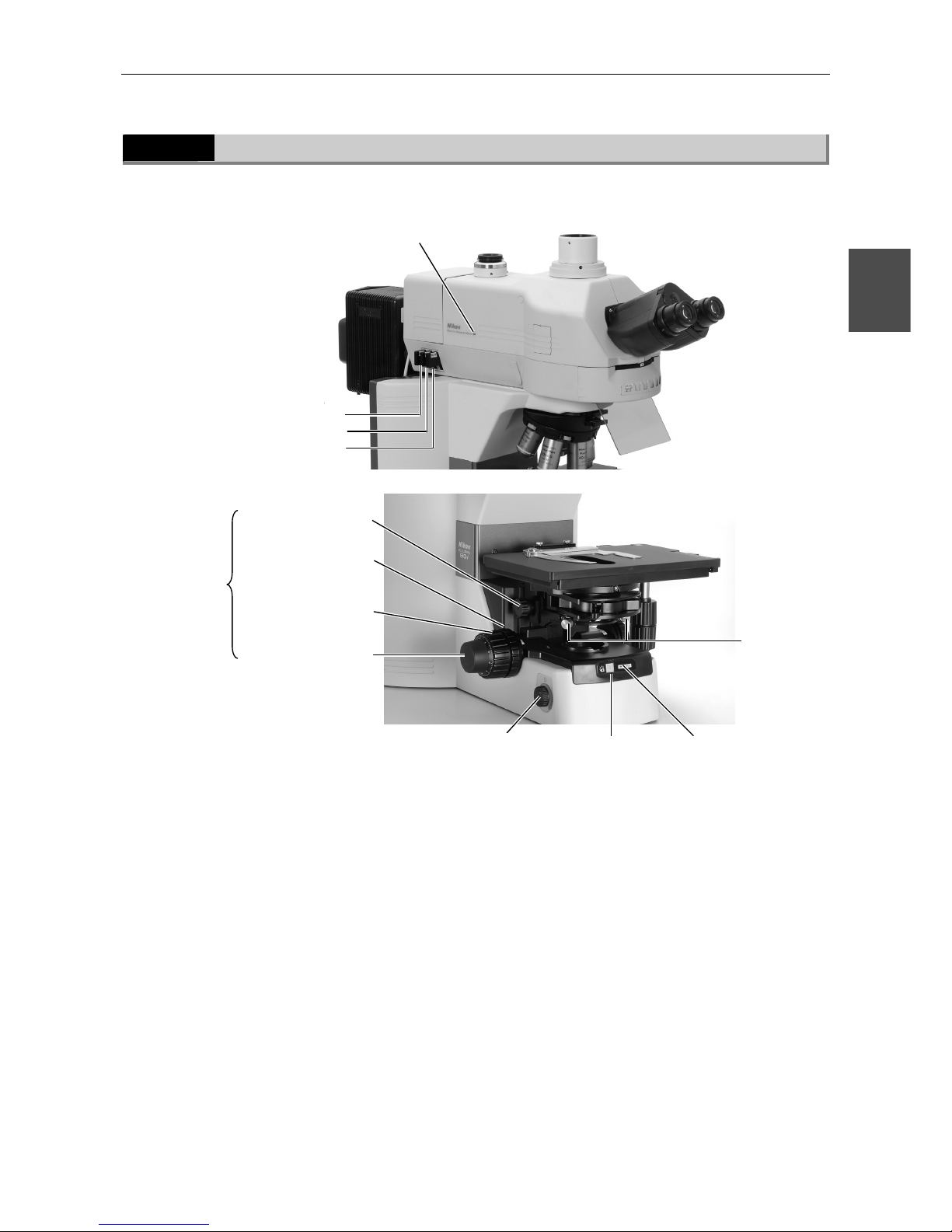
3.2.1
Right view
Diopter adjustment
ring
Optical path
switching lever (2)
Coarse focus upper-limit clamp
Aperture diaphragm lever
Field diaphragmknob
Filter IN/OUT
switch
X stage knob
Y stage knob
Camera head
Camera cable
C mount adapter
C-mount adapter retaining screw
Excitation method
switchover turret
Excitation ID tag pocket
Fine focus knob
Filter cube mountin
g
section
(inside)
Optical path
switching lever (1)
Zoom knob
X ステージハンド
Field diaphragm
open/close lever (for
Epi-fluorescent light)
Aperture diaphragm
open/close lever (for
Epi-fluorescent light)
Field diaphragm
centering holes
Aperture
diaphragm
centering holes
(Provided on the left side
in certain products)
Page 41
Chapter 3 Part Names and Microscopy Procedures(With DIH-M Mounted)
3.2 Names of Parts Used to Make Adjustments
39
3
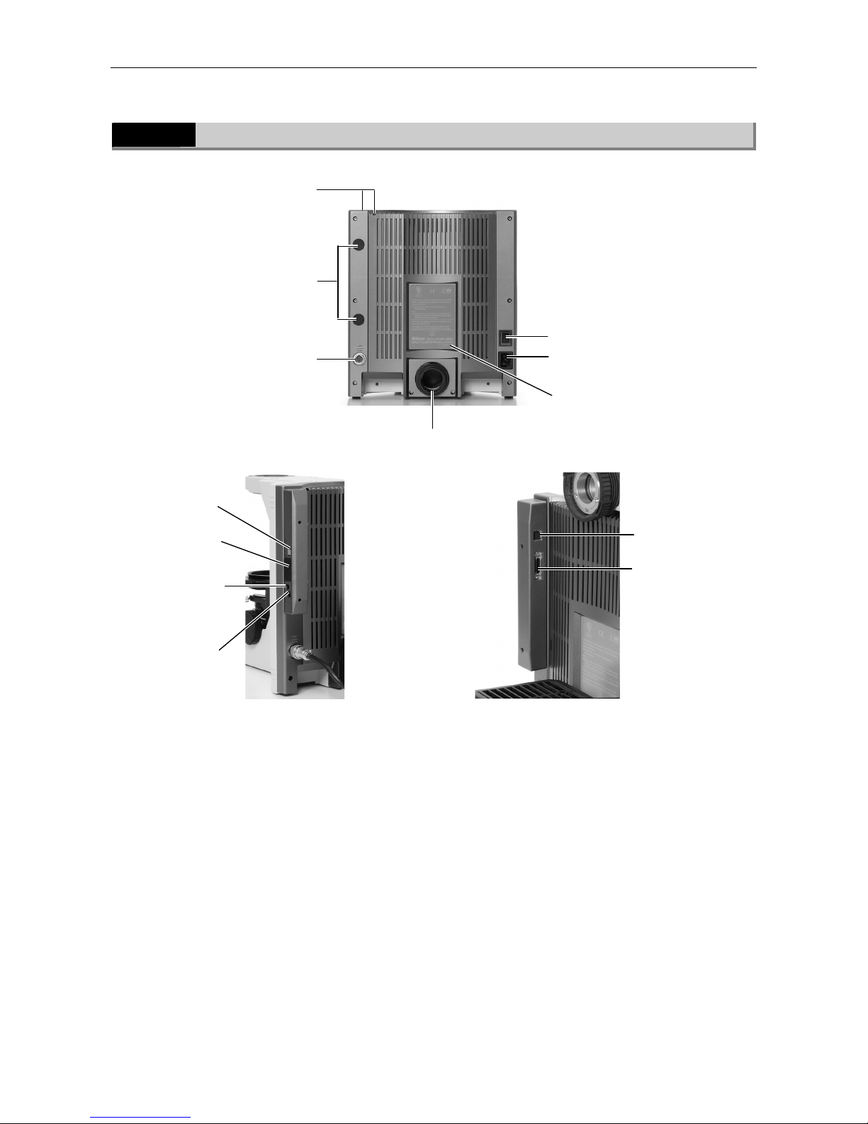
3.2.2
Left view
ND4 filter slider
ND16 filter slider
ND8 filter slider
DIH-M Power ON indicator
Coarse focus
knob
Fine focus knob
Power ON indicator
Preset switch
Condenser focus knob
Condenser
centering
screw
Coarse focus torque
adjustment knob
Brightness control knob
(Provided on
the right side
in certain
products)
Page 42
Chapter 3 Part Names and Microscopy Procedures(With DIH-M Mounted)
3.2 Names of Parts Used to Make Adjustments
40
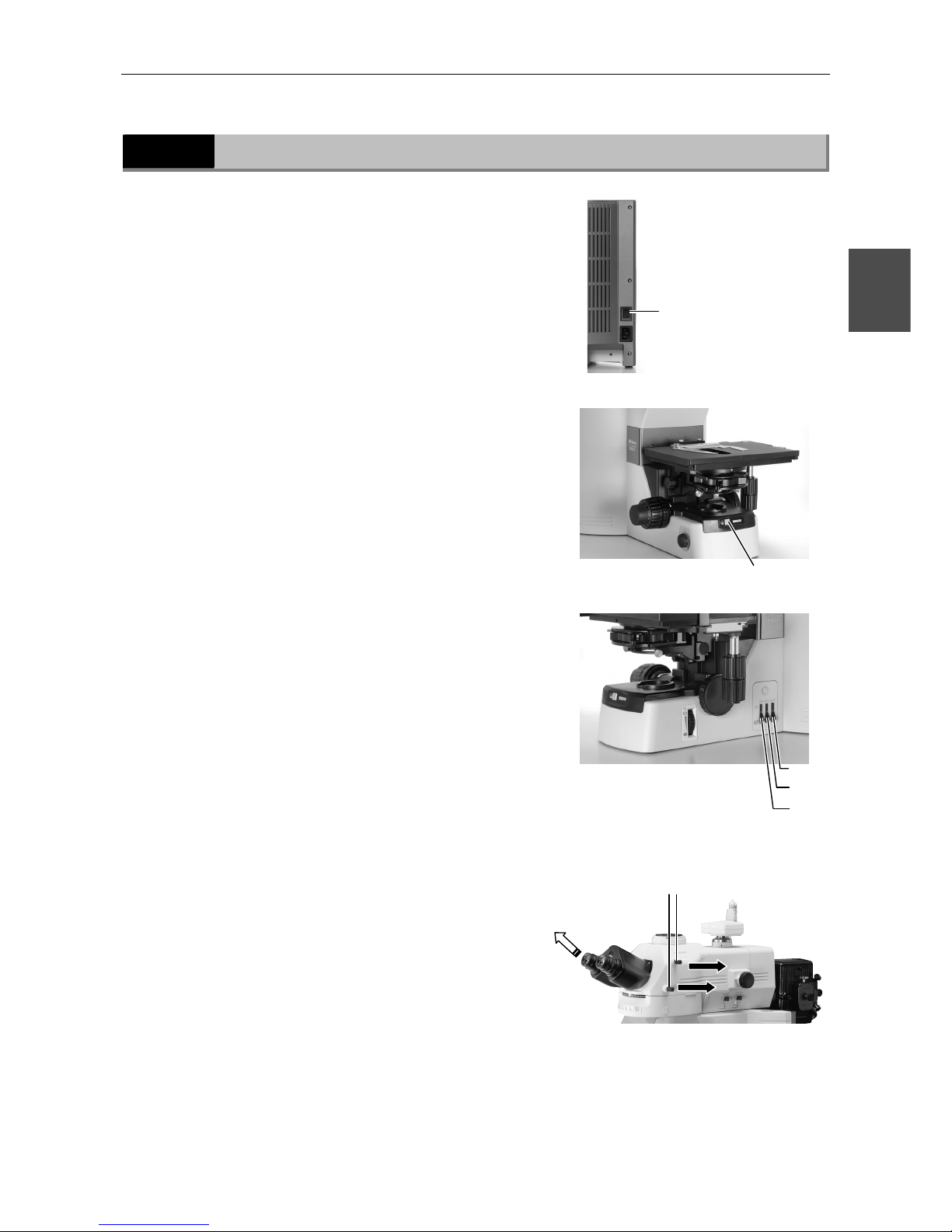
3.2.3
Rear view (without accessory device)
Tool storage compartmen
t
Power switch
AC inle
Input voltage indication
Lamphouse mounting section
Lamphouse
connector
port
C-Box power
switch
Not used
Connector for
Epi-illumination
shutter o
p
en/close
hand switch
AC adapter inle
t
Outside the C-Box
Inside the C-Box
Intelligent nosepiece
connector
DIH-M
connector
C-Box mounting sections
Page 43
Chapter 3 Part Names and Microscopy Procedures(With DIH-M Mounted)
3.3 Bright-Field Microscopy
41
3
3.3
Bright-Field Microscopy
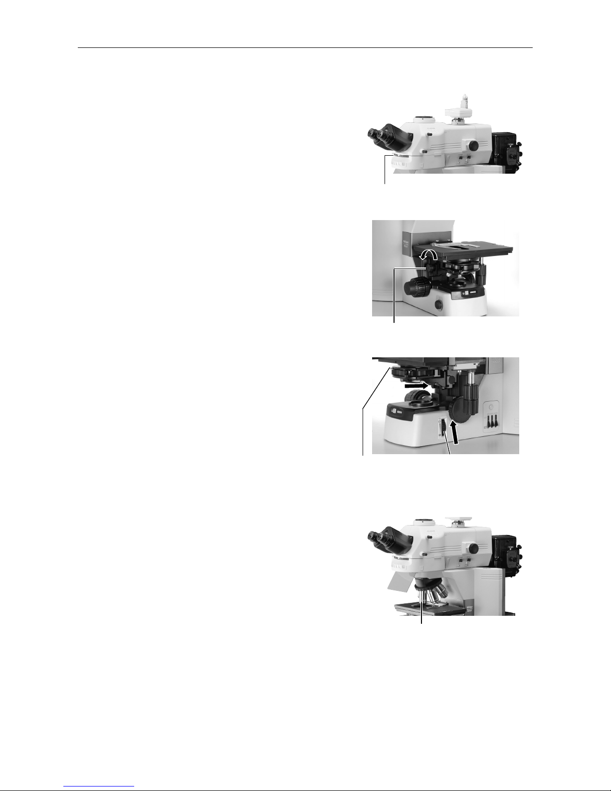
1
Turn on power.
The C-Box and the power source for the
Epi-illumination do not need to be turned on. If
they are turned on, keep the shutter of the
Epi-illumination closed.
(The shutter is automatically kept closed when the
power switch is turned on. Do not touch the hand
switch. If the shutter is opened accidentally, press
the hand switch once again to close the shutter.)
2
Press the preset switch.
3
Move the ND8, ND32, and NCB11
filters into the optical path.
4
Pull out both optical path
switching levers and direct the
full optical path toward the
binocular section.
Press the power switch to
the "|" position.
Press the preset switch.
ND8
ND32
NCB11
T
he full optical
path directed
toward the
binocular
section
Pull out both upper and
lower optical path
switchin
g
levers.
Page 44
Chapter 3 Part Names and Microscopy Procedures(With DIH-M Mounted)
3.3 Bright-Field Microscopy
42
5
Rotate the excitation method
switchover turret to set it a
position where no fluorescent
cube is installed.
6
Raise the condenser to the
uppermost position.
7
Fully open the field diaphragm
and aperture diaphragm.
8
Set the 10x objective into the
optical path.
Fully open the aperture
diaphragm using the
aperture diaphragm
lever.
Fully open the field
diaphragm using the
field diaphragm knob.
Raise the condenser using the
condenser focus knob.
Select the 10x objective.
Rotate the excitation method
switchover turret.
Page 45
Chapter 3 Part Names and Microscopy Procedures(With DIH-M Mounted)
3.3 Bright-Field Microscopy
43
3
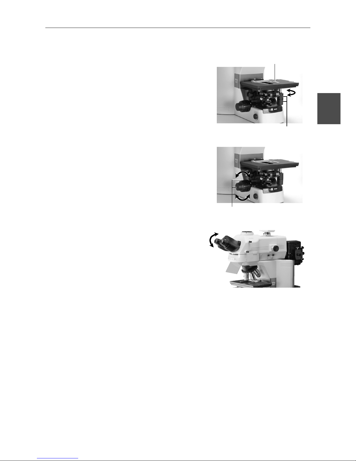
9
Set a specimen and move the
portion to be viewed into the
optical path.
10
Focus on the specimen.
11
Adjust the diopter and the
interpupillary distance.
Refer to "8. Diopter Adjustment" and "9.
Interpupillary Distance Adjustment" in the separate
Reference manual.
Set a specimen and secure in
place using the specimen holder.
Move the portion to be viewed into the
optical path using the XY stage knobs.
Focus on the specimen using
the coarse and fine focus knobs.
Page 46
Chapter 3 Part Names and Microscopy Procedures(With DIH-M Mounted)
3.3 Bright-Field Microscopy
44
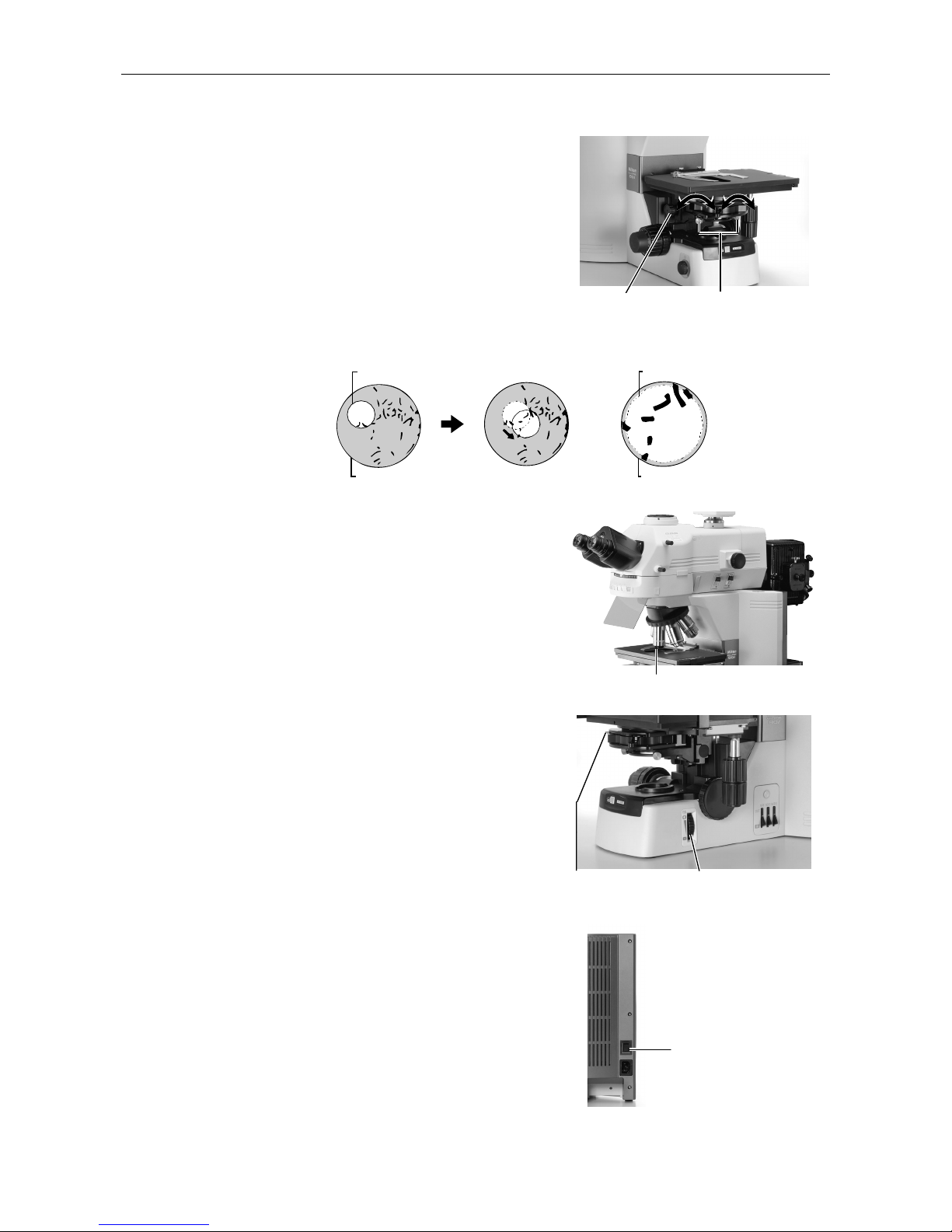
12
Focus and center the condenser.
Refer to "11. Adjustment of Condenser Position" in
the separate Reference manual.
13
Switch to the desired objective
and view the specimen.
Adjust the field diaphragm and
aperture diaphragm each time
you change objectives.
ield diaphragm:
Set slightly narrower than the margins of
the field of view.
erture diaphragm:
70% to 80% of the maximum numerical
aperture (N.A.) of the objective
14
Turn off power after completing
observations.
Select the desired objective.
Press the power switch
to the "◯" position.
Center the condenser
using the condenser
centering screws.
Focus the condenser using
the condenser focus knob.
Aperture diaphragm
lever
Field diaphragm knob
Field diaphragm
Eyepiece field of view
Field diaphragm
Eyepiece field of view
Page 47
Chapter 3 Part Names and Microscopy Procedures(With DIH-M Mounted)
3.4 Epi-fluorescence Microscopy
45
3
3.4
Epi-fluorescence Microscopy
Before microscopy...
• Check the cumulative operating hours of the lamp in the Epi-illumination
attachment. Replace the lamp if its cumulative operating hours exceed the
recommended maximum service life.
• Use non-fluorescent slide glass.
• Use non-fluorescent immersion oil.
• To keep specimen colors from fading, keep the shutter closed when not
performing microscopy.
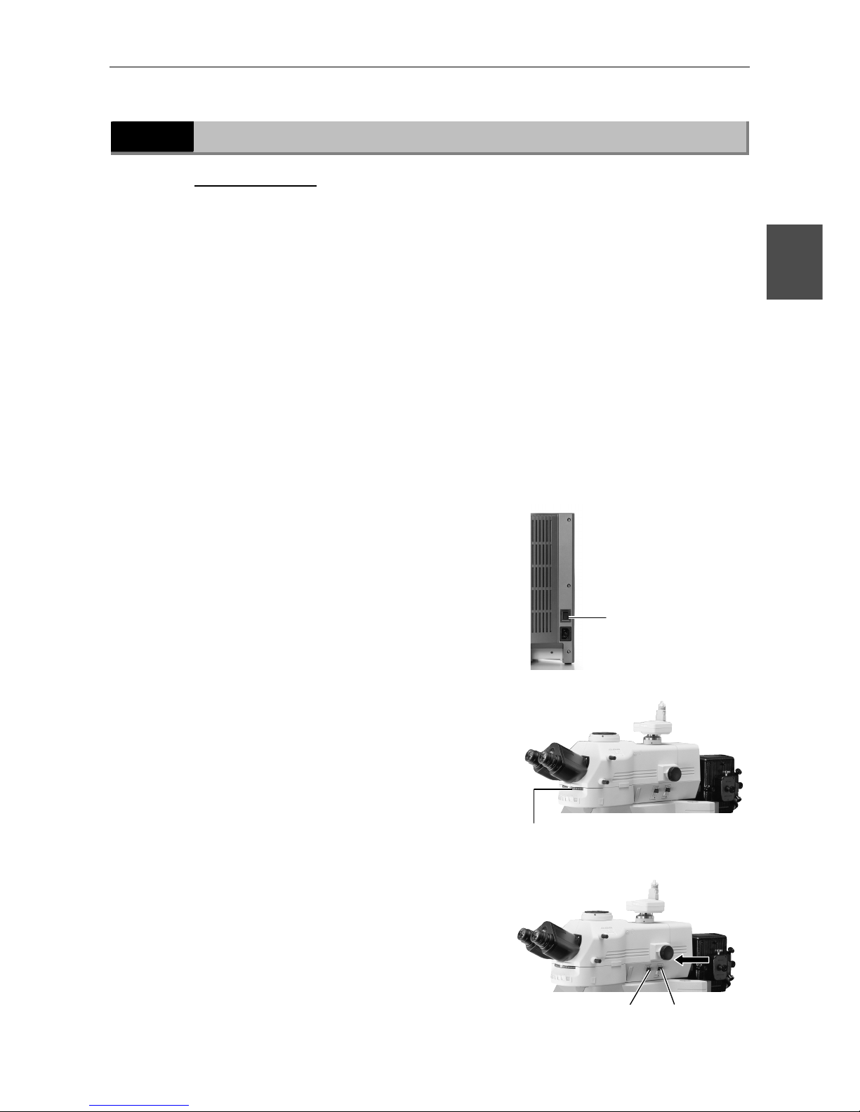
1
Perform steps 1 through 11 in "3.3 Bright-Field
Microscopy."
2
Lower the condenser, or remove the condenser and mount
the shielding tube in its place.
3
Turn off the microscope power
switch.
4
Move the filter cube for the
excitation method to be used
into the optical path.
5
Fully open the field diaphragm
and aperture diaphragm of the
Epi-illumination.
Push to fully open
the field diaphragm.
Select a cube using the excitation
method switchover turret.
Press the power switch
to the "◯" position.
Push to fully open
the aperture
Page 48
Chapter 3 Part Names and Microscopy Procedures(With DIH-M Mounted)
3.4 Epi-fluorescence Microscopy
46
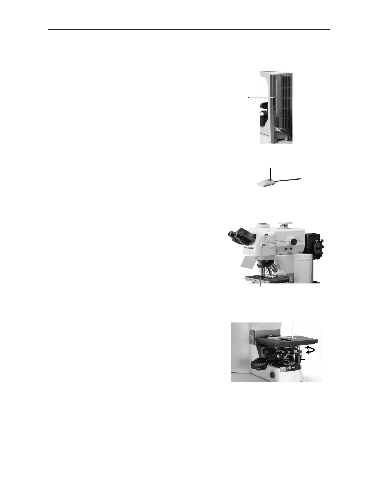
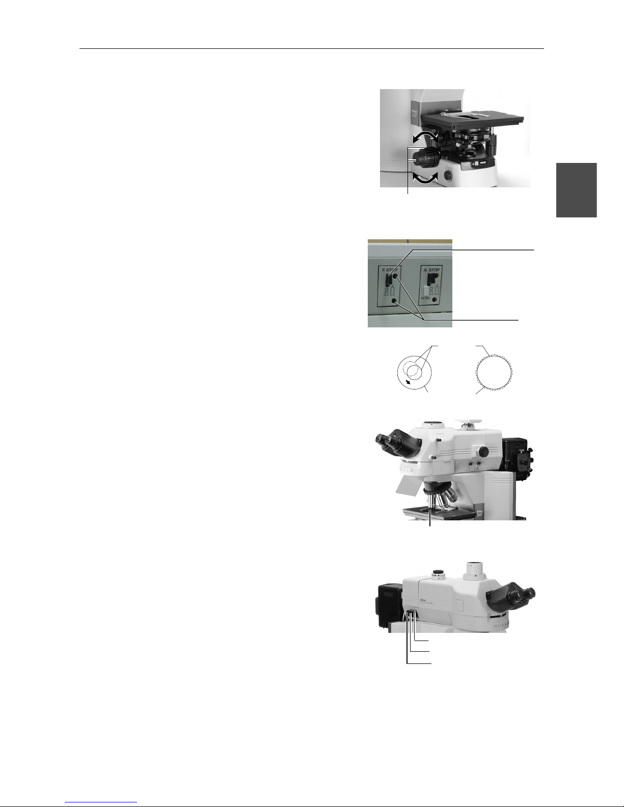
6
Switch on power for the C-Box
and Epi-illumination light source.
(Note that the shutter for the
Epi-illumination is closed
automatically.)
7
Press the hand switch to open
the shutter of the
Epi-illumination and center the
lamp. (Refer to the lamp
operating manual.)
8
Set the 10x objective into the
optical path.
9
Set a specimen and move the
portion to be viewed into the
optical path.
Select the 10x objective.
Set a specimen and secure in place
using the specimen holder.
Move the portion to be viewed into the
optical path using the XY stage knobs.
C-Box
power switch
Push to open the shutter.
Page 49
Chapter 3 Part Names and Microscopy Procedures(With DIH-M Mounted)
3.4 Epi-fluorescence Microscopy
47
3
10
Focus on the specimen.
11
Center the field diaphragm of the
Epi-illumination attachment.
Refer to "4. Epi-fluorescent Field Diaphragm" in
"17. Fluorescence Observation" of the separate
Reference manual.
12
Switch to the desired objective
and view the specimen.
• Use the ND filters for the fluorescence
attachment to adjust brightness.
• Adjust the field diaphragm so that it extends
slightly beyond the field of view.
• The image brightness can be adjusted with
the aperture diaphragm. Complete centering
before using the aperture diaphragm.
• When using oil immersion objectives, apply
immersion oil between the specimen and the
objective.
Focus on the specimen using the
coarse and fine focus knobs.
Field
dia
p
hragm
image
Field diaphragm
open/close lever
Field diaphragm centering
screw holes
Eyepiece
field of view
Select the desired objective.
ND4 filter slider
ND16 filter slider
ND8 filter slider
Page 50
Chapter 3 Part Names and Microscopy Procedures(With DIH-M Mounted)
3.4 Epi-fluorescence Microscopy
48
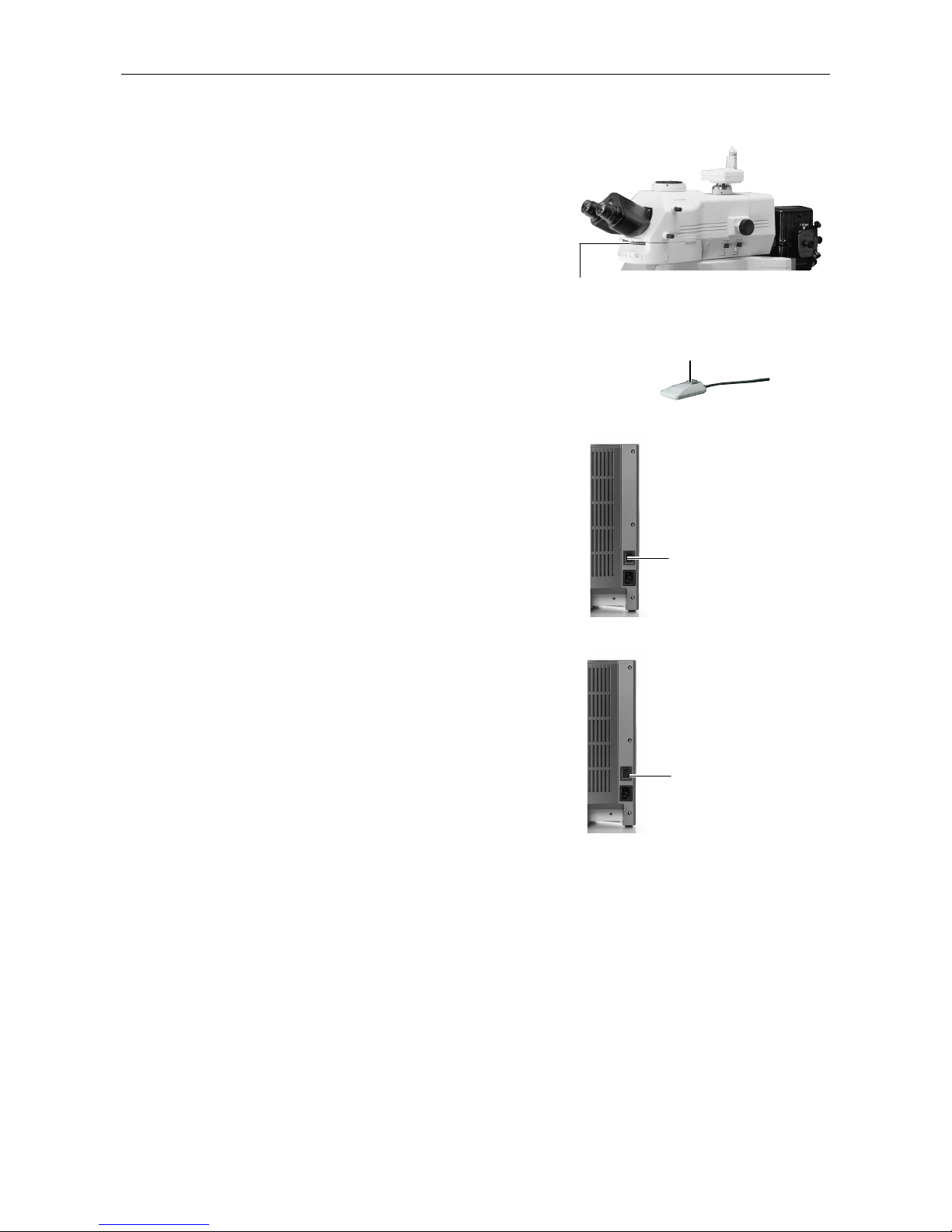
13
To return to bright-field
microscopy.
• Close the shutter of the Epi-illumination and
block the Epi-illumination.
• Rotate the excitation method switchover
turret to move the position where no filter
cube is installed into the optical path.
• If the condenser is not mounted, install the
condenser, then focus and center the
condenser. (Refer to step 12 of bright-field
microscopy.)
• Turn on the microscope power switch to turn
on the diascopic light source.
14
Turn off all power switches after
completing observations.
Press the power switch
to the "◯" position.
Use the excitation method switchover
turret to change cubes.
Press the switch to the
"|" position.
Close the shutter.
Page 51
Chapter 3 Part Names and Microscopy Procedures(With DIH-M Mounted)
3.5 Photomicroscopy
49
3
3.5
Photomicroscopy
For detailed discussions of the camera, photomicroscopic software, and PC, refer to the
operating manuals provided with the respective products. The following instructions assume a
DS-5M digital camera and DS-L1 camera control unit.
1
Adjust the microscope for proper image observation.
See the directions given earlier in "1. Bright-Field Microscopy" or "2. Epifluorescence
Microscopy."
2
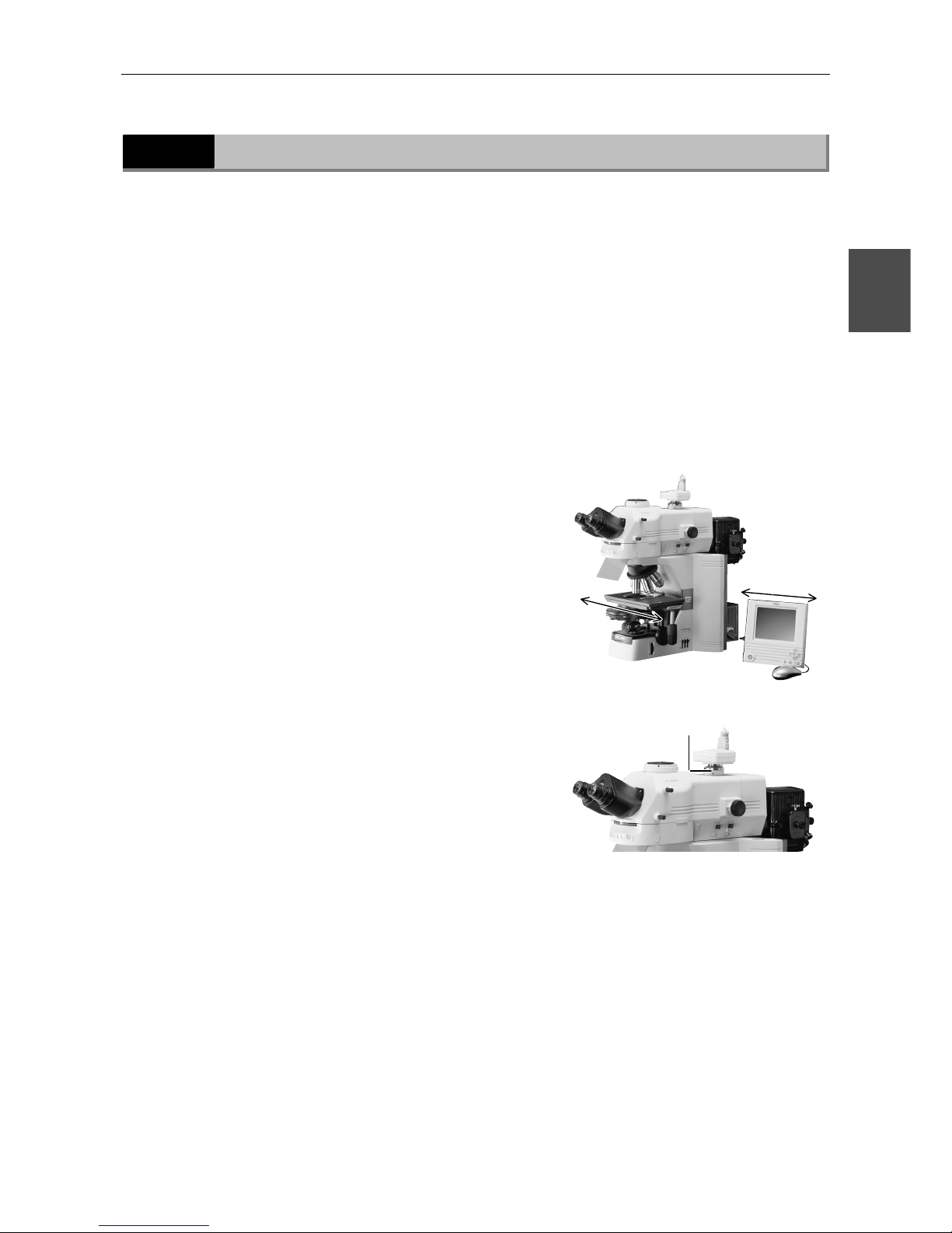
Adjust the camera head mounting position until the image is
displayed properly.
(1) Adjustment based on stage motion direction
Loosen the C-mount adapter retaining screw
and adjust the camera position so that
moving the stage forward-backward or
left-right moves the image on the monitor in
the same direction. After making the
appropriate adjustments, tighten the screw
firmly.
3
Make camera settings.
For a detailed discussion of this topic, refer to the operating manual provided with the camera.
When using the DS-L1, you must choose and enter at least the following information:
• Folder for data storage
• Name of file to be saved (You can select "Auto.")
• File format and file size
• Date and destination of data
C-mount adapter
retaining screw
(A)
(B)
Adjusting (A) and (B)
Page 52

Chapter 3 Part Names and Microscopy Procedures(With DIH-M Mounted)
3.5 Photomicroscopy
50
4
Select the camera scene mode suitable for the microscopy
method.
5
Set the camera white balance.
To adjust white balance, press the WB button while capturing an image of a clear section of a
specimen slide. (For fluorescent photomicrography, adjust white balance under normal lighting
conditions before shooting.)
6
Capture and save images.
Adjust image brightness using the camera exposure compensation function.
Check the image using the Freeze button.
If the image is acceptable, press the CAPT. button to save the image.
(The operating procedure differs if DF/FL scene mode is selected. For a detailed discussion of
this topic, refer to the operating manual provided with the camera.)
Page 53
51
Assembly
4
4
1
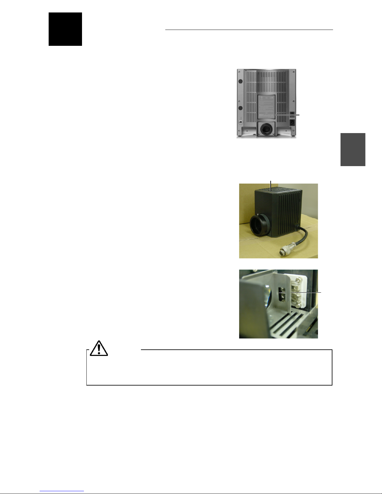
Checking the Input Voltage
Check the input voltage indicated on the back of
the microscope. Use the microscope only if this
indication matches the power supply voltage for the
area in which the microscope will be used.
Note: If the voltage indication and supply voltage
differ, do not attempt to use the microscope.
Contact your nearest Nikon representative to seek
advice.
2
Installing a Lamp
(1) Loosen the lamphouse-cover fixing screw and
lift the lamphouse cover to remove.
(2) Attach the lamp to the lamp plug.
Avoid touching the bare lamp bulb with your
bare hands.
Use the lamp type specified. Using an
unspecified lamp may cause malfunction or
fire. Refer to Chapter 8 for the specified lamp.
(3) Replace the cover and tighten the screw.
The lamphouse cover must be attached. Failure to replace the lamphouse cover
may result in burns or fire from the heat generated by the lamp.
Input voltage
indication
Lamp
plug
Lamphouse-cover fixing screw
Back
CAUTION
Page 54
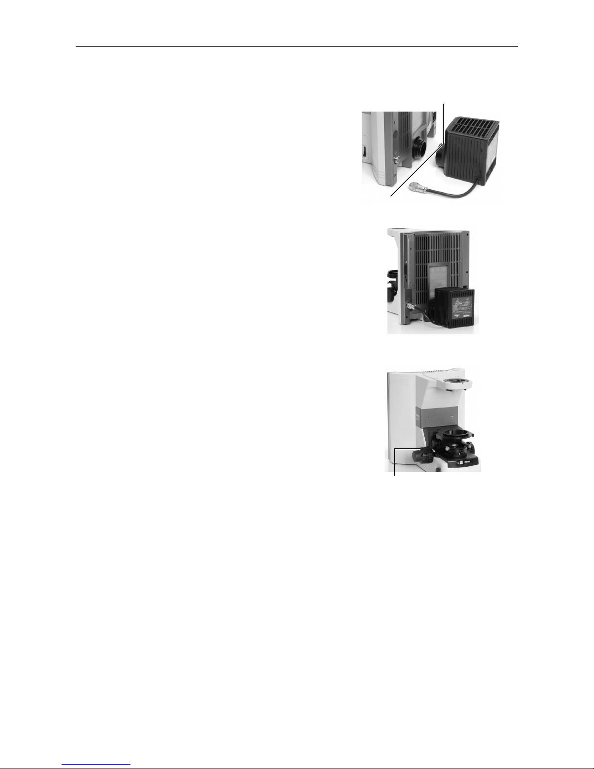
Chapter 4 Assembly
52
3
Attaching the lamphouse
(1) Attach the lamphouse to the back of the
microscope and fix it with the fixing screw.
(2) Attach the connector.
4
Installing a Stage
(1) Turn the coarse focus knob to remove the
cushioning material from the elevating
section.
Attaching the lamphouse
Attaching the connector
T
urn this to lower the elevating stage.
Fixing screw
Page 55
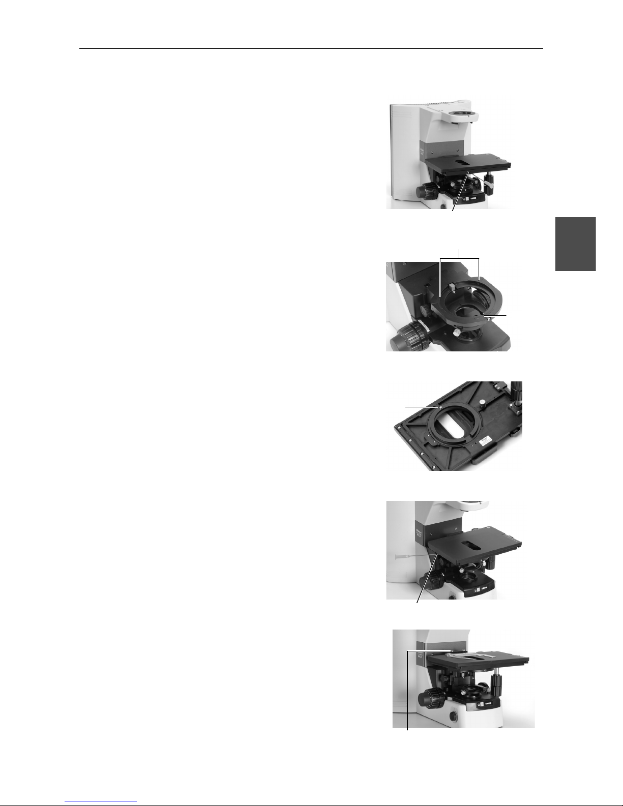
Chapter 4 Assembly
53
4
(2) Place the stage on the elevating section and
fix into place with two screws.
(For the stage with a centering function, place
the stage on the elevating section by aligning
the projection on the back of the stage with
the groove of the elevating section.)
(3) Place a specimen holder on the stage and
secure with screws.
Fixing the stage
Fixing the stage with centering function
Fixing the specimen holder
Groove
Stage with centering function
Projection
Back of the stage with centering function
Screws fixing the stage
Page 56
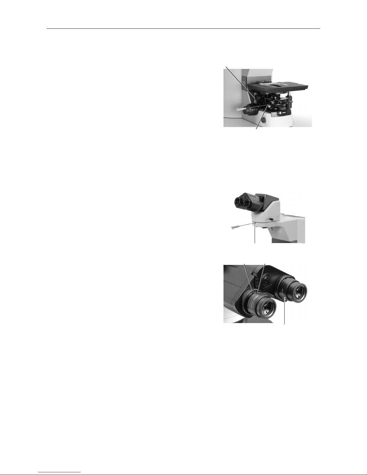
Chapter 4 Assembly
54
5
Installing a Condenser
(1) Turn the coarse focus handle until the
elevating section is raised to the highest
position.
(2) Turn the condenser focus knob until the
elevating section is brought to the lowermost
position.
(3) Insert a condenser and adjust so that it faces
toward the front. Secure in place with a tool
stored in the back of the microscope.
(4) Turn the condenser focus knob until the
elevating section is raised to the uppermost
position.
6
Installing an Eyepiece Tube directly
(1) Place an eyepiece tube on the microscope
arm.
(2) Attach the eyepiece by aligning the projection
of the eyepiece tube sleeve with the notch at
the objective.
(3) Attach a screw hole protection sticker
provided with the system to the bolt hole
found on the top surface of the arm.
Fixing condenser
Condenser focus knob
Eyepiece attached in place
Projection
Notch
Fixing the eyepiece tube
Page 57
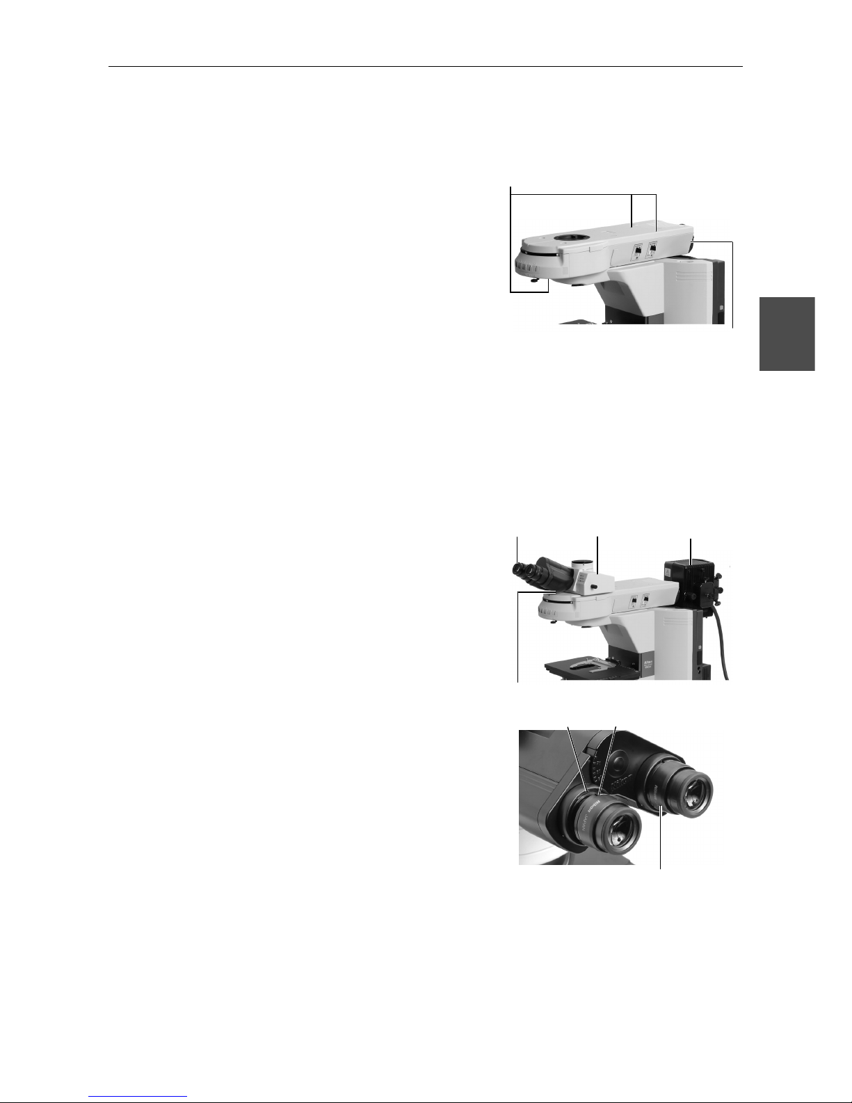
Chapter 4 Assembly
55
4
7
Installing an Epi-illumination attachment
(1) Place an Epi-illumination attachment on the
microscope arm and fix it with a screw at the
front of the arm.
(2) Secure in place with two screws at the back of
the Epi-illumination attachment.
(3) Attach a screw hole protection sticker
provided with the system to the bolt hole.
(4) Attach a mercury lamphouse to the bayonet
mount on the back. (For more information,
refer to the instruction manual provided with
the super high-pressure mercury lamp power
supply.)
1) Attach a collector lens to the lamphouse.
2) Turn the bayonet mount clockwise (viewed
from the back) as far as it will go.
3) Insert the lamphouse into position.
4) Turn the bayonet mount anticlockwise
(viewed from the back) to lock the
lamphouse.
5) Attach a mercury lamp.
6) Connect the mercury lamphouse to the
mercury lamp power supply.
(5) Attach the eyepiece tube.
(6) Attach the eyepiece by aligning the projection
of the eyepiece tube sleeve with the notch at
the objective.
Screws to fix the Epi-illumination
attachment (three screws in total)
Eyepiece tube
Mercury
lamphouse
Eyepiece attached in place
Projection
Notch
Bayonet mount
Eyepiece tube fixing screw
Eyepiece
Page 58
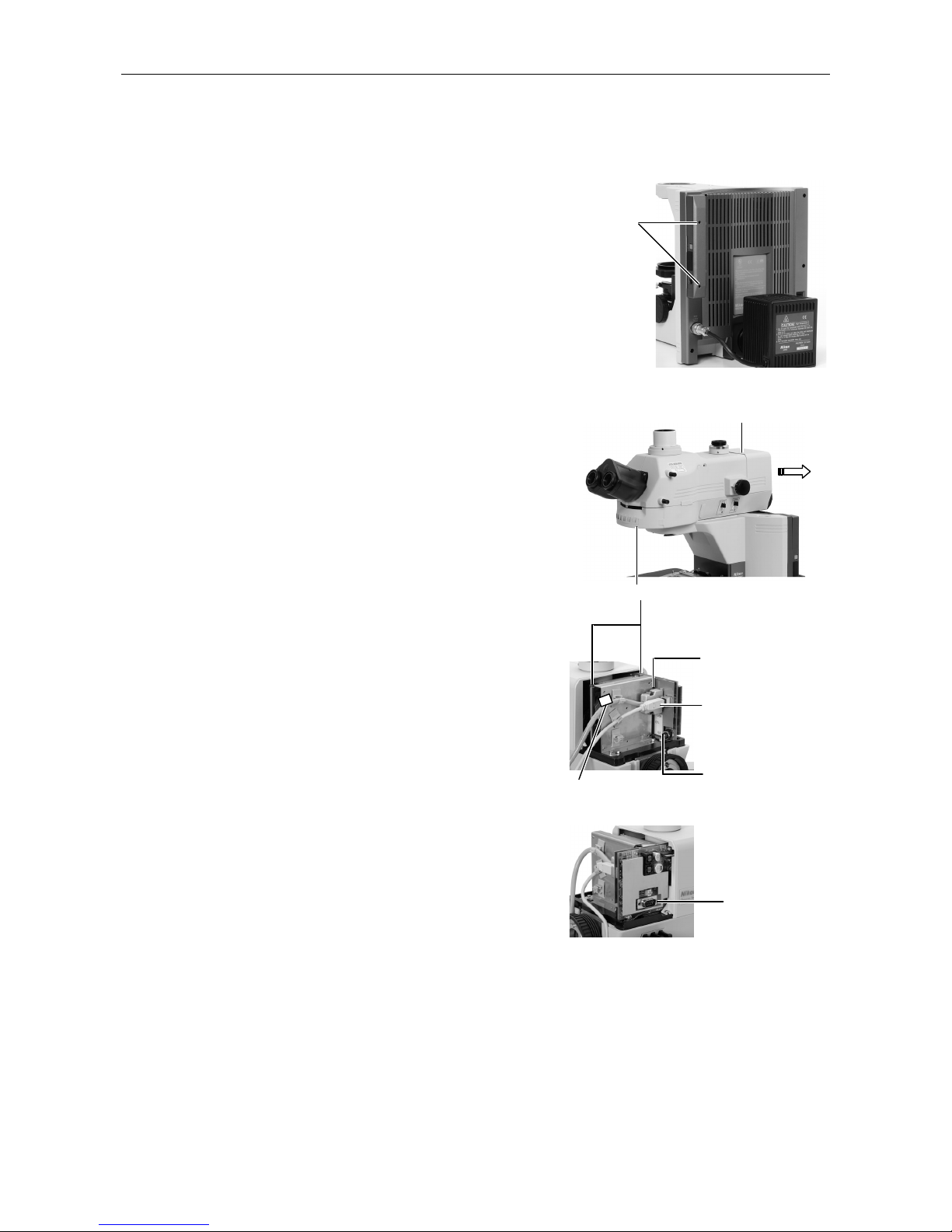
Chapter 4 Assembly
56
8
Using the DIH-M
(1) Attach two C-BOXs to the back of the
microscope with screws.
(2) Place the DIH-M on the microscope arm and
fix it with a screw at the front of the arm.
(3) Remove the back cover of the DIH-M by
loosening the two screws.
(4) Fix the DIH-M to the microscope with two
screws inside the arm.
(5) Connect the ferrite core side of the control
cable to the CTL connector. When inspecting
DIH-M conditions, also attach the USB cable.
In this case, the other end of the USB cable is
connected to the PC.
(The control cable and the USB cable are
provided with the DHI-M.)
(6) Replace the cover.
C-BOX
fixing
Viewed from the
other side
Cover fixing screw
DIH-M fixing screw (Three positions
)
Control cable
USB cable (Always
connect this cable
when inspecting
DIH-M conditions.)
For maintenance
(not used)
Interlock connector
for C1 (Used only
with C1 attached)
Ferrite core
Page 59
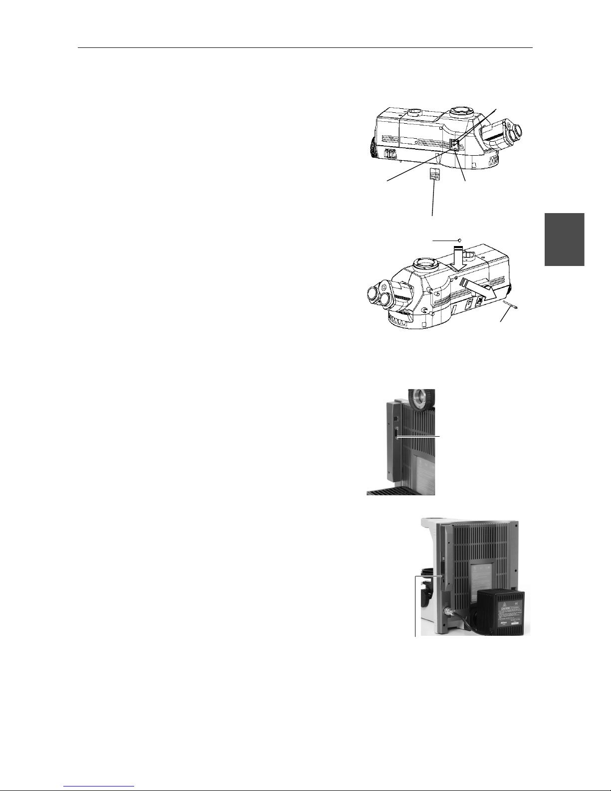
Chapter 4 Assembly
57
4
(7) Connect the control cable attached to the
DIH-M to the C-BOX.
1) Remove the cover on the left side of the
DIH-M.
2) Loosen the optical path switching section
fixing board mount screw.
3) Loosen the two optical path switching
section fixing screws and remove the clamp
from the inside of the optical path switching
section. (This frees the optical path
switching lever.)
4) Move the fixing board slightly forward with
the fixing screws attached, then tighten the
mount screw.
5) Replace the cover.
6) Loosen the zooming section fixing screw to
remove the clamp from the DIH-M.
7) Attach the blind cap provided.
(8) Connect the control cable attached to the
DIH-M to the C-BOX.
(9) Attach the hand switch for the
Epi-illumination shutter to the C-BOX.
Attach the hand switch fo
r
the Epi-illumination shutte
r
here.
Connect the control
cable attached to the
DIH-M here.
Fixing screws for optical
path switching section
Mount screw for fixing
board for optical path
switching section
Cover
Fixing board for
optical path
switching section
Blind cap
Fixing screw for
zooming section
Page 60
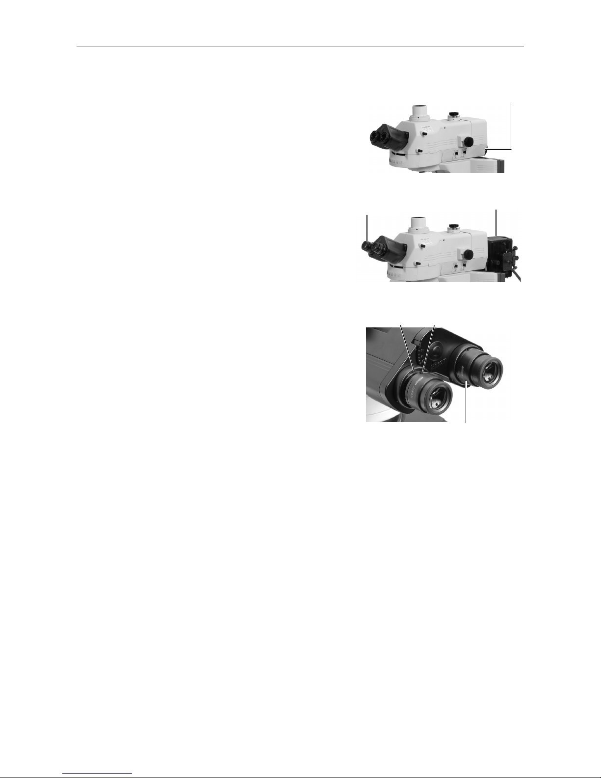
Chapter 4 Assembly
58
(10) Attach the mercury lamphouse to the back of
the bayonet mount. (For more information,
refer to the instruction manual provided with
the super high-pressure mercury lamp power
supply.)
1) Attach a collector lens to the lamphouse.
2) Turn the bayonet mount clockwise (viewed
from the back) as far as it will go.
3) Insert the lamphouse into position.
4) Turn the bayonet mount anticlockwise
(viewed from the back) to lock the
lamphouse.
5) Attach a mercury lamp.
6) Connect the mercury lamphouse to the
mercury lamp power supply.
(11) Attach the eyepiece by aligning the projection
of the eyepiece tube sleeve with the notch at
the objective.
Projection
Notch
Bayonet mount
Mercury lamphouse
Objective
Eyepiece attached in place
Page 61
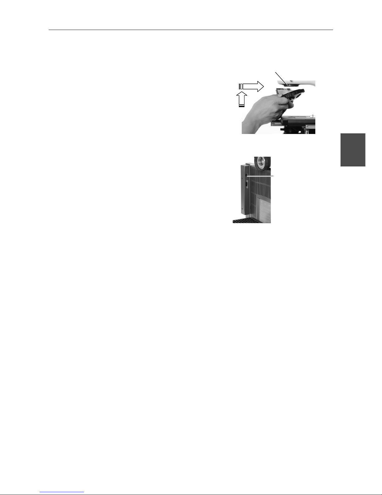
Chapter 4 Assembly
59
4
9
Installing a Revolving Nosepiece
(1) Lift the revolving nosepiece from a position
just forward of the point directly below the
fitting part and slide toward the back to
attach. (Continue sliding the revolving
nosepiece until its front position is aligned
with that of the fitting part.)
(2) Secure with the screw.
(3) When using the intelligent revolving
nosepiece, connect the connector attached to
the revolving nosepiece to the upper port
found inside the C-BOX.
10
Installing Objectives
Screw objectives into the revolving nosepiece. When installing the objective in this way, make
sure that the magnification of the objective increases when the revolving nosepiece is turned
clockwise (clockwise when viewed from above the eyepiece).
Fixing the revolving nosepiece
Connect the connector
here when using the
intelligent revolving
nosepiece.
Page 62
Chapter 4 Assembly
60
11
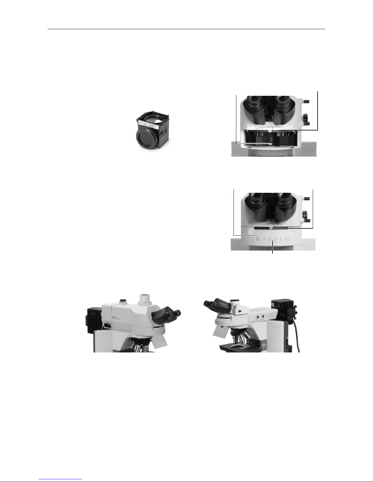
Installing Filter Cubes and a Light Shield (when the
Epi-illumination attachment or the DIH-M is installed)
(1) There is a front cover below the eyepiece. Pull
out the cover to remove.
(2) Insert a filter cube into position.
(3) Insert a nameplate into the position with the
same address as the one indicated on the filer
cube select knob on the right side of the
microscope.
(4) Turn the filter cube select knob and insert a
filter cube into the remaining open position.
(5) Replace the cover.
(6) Attach a light shield to the front bottom of the
fluorescent unit with screws.
Filter cube fitting part
Excitation switching turret
Address
indication
Address
indication
Address
indication
Nameplate
Filter cube
Light shield attached
(with DIH-M)
Light shield attached
(with Epi-illumination attachment)
Page 63
Chapter 4 Assembly
61
4
12
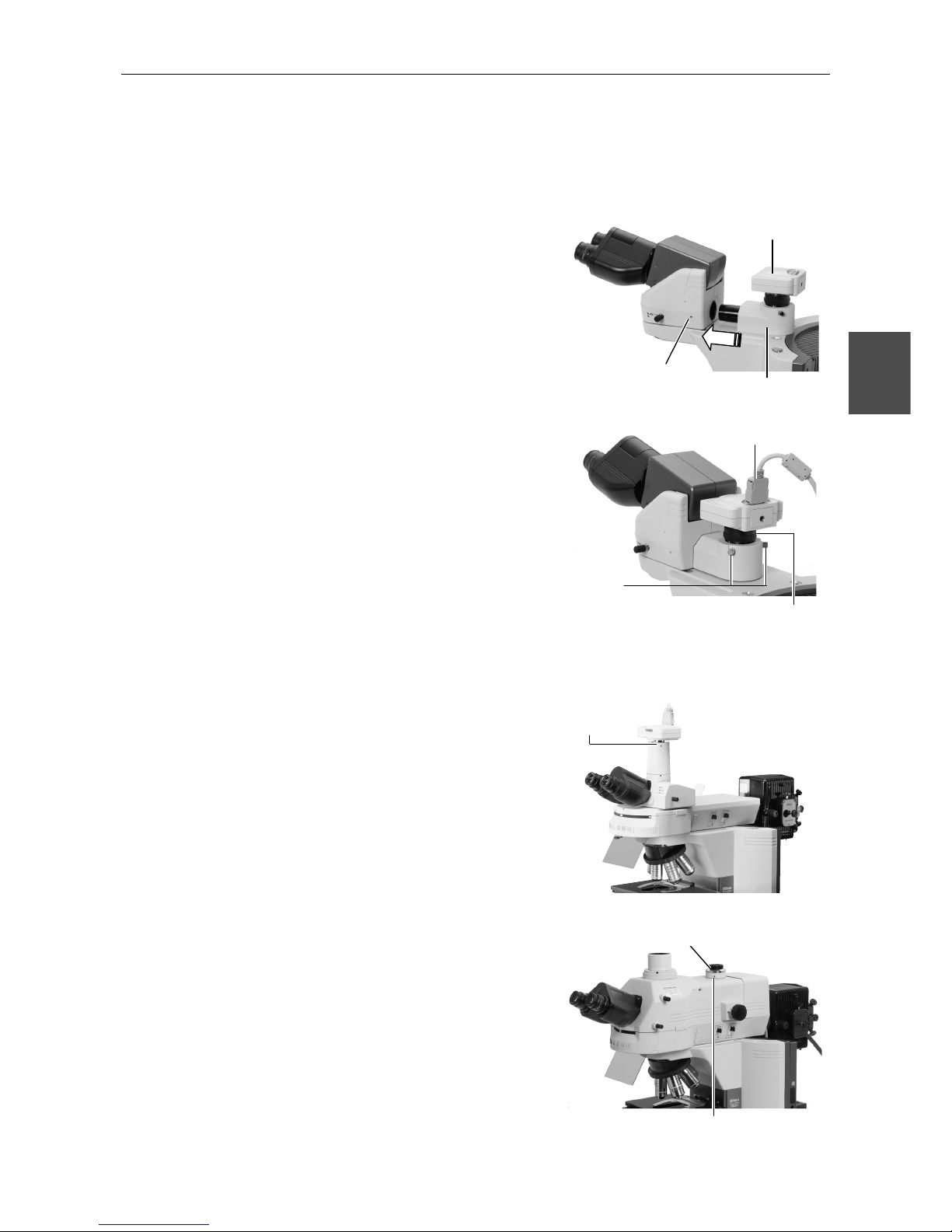
Installing a Camera (when using a camera)
12-1 When attaching to the ergonomic binocular tube:
(1) To attach a camera head, screw it into the C
mount on the DSC port.
(2) Remove the rear cover of the ergonomic
binocular tube and insert the DSC port.
(3) Secure the DSC port into place with screws.
(4) Attach the camera cable to the camera head.
(Adjust the fitted position before using the
camera. Refer to 2.4 operation procedure.)
12-2 When attaching to the trinocular eyepiece tube:
(1) Attach the camera head to the trinocular
eyepiece tube using the C-mount adapter.
(2) Attach the camera cable to the camera head.
(Adjust the fitted position before using the
camera.)
12-3 When attaching the DIH-M:
(1) Attach the camera head to the DIH-M using
the C-mount adapter that is near the rear
port.
(2) Attach the camera cable to the camera head.
(Adjust the fitting position before using the
camera.)
Camera cable
fitting part
Camera head
DSC port
Camera focus position
adjusting screws
Camera
centering screw
Securing the DSC port
Fixing the C-mount adapter
C-mount adapter
C-mount
ada
p
ter fixing
screw
Page 64
Chapter 4 Assembly
62
13
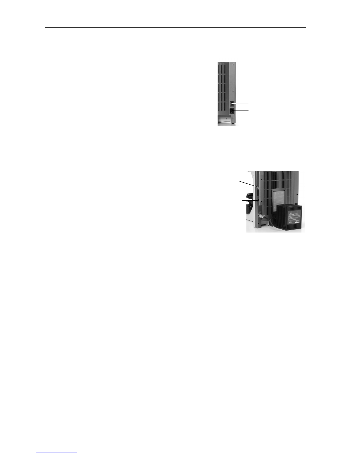
Installing the Power Cord
(1) Check to confirm that the microscope power
switch is off.
(2) Insert one end of the power cord into the AC
inlet at the back of the microscope.
(3) Insert the other end of the power cord into
the wall outlet.
Use only the specified power cord.
Refer to Chapter 8 for the power cord
specified.
14
Connecting the AC Adapter (when using the DIH-M)
(1) Confirm that the power switch of the C-BOX
(attached to the back of the microscope) is off
(the button projects out).
(2) Connect the AC adapter to the bottom port on
the front of the C-BOX.
(3) Connect the AC adapter to the wall outlet with
the power cord.
Use only the AC adapter and power cord
specified.
Refer to Chapter 8 for the specified AC
adapter and power cord.
Microscope assembly is now complete.
Power switch for the
microscope
AC inlet
C-BOX power
switch
Connect the
AC adapter
here.
Right side of the back
Page 65
63
Replacing Consumables
5
5
5.1
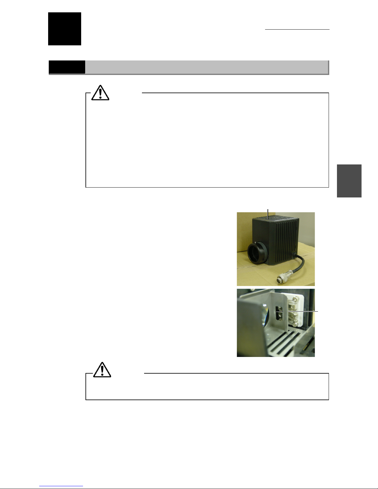
Replacing the lamp
• Be careful to avoid burns:
Wait until the lamp and nearby parts have cooled before attempting to replace
the lamp.
• Be careful to avoid electrical shock:
Turn off the power switch and unplug the power cord from the outlet.
• Be careful to avoid abnormal heat generation:
Use only the lamp specified.
• Be careful to avoid actions that might reduce lamp service life:
Avoid touching the bare lamp bulb with bare hands. Soiling will reduce the
service life of the lamp.
(1) Loosen the screw and lift the cover to
remove.
(2) Remove the old lamp.
(3) Replace with a new lamp.
Avoid touching the bare lamp bulb with bare
hands.
Use only the lamp specified. Refer to chapter
8 for the specified lamp.
(4) Replace the cover and fix it with the screw.
The lamphouse cover must be attached. Failure to replace the lamphouse cover
may result in burns or fire from the heat generated by the lamp.
Lamp
plug
Lamphouse cover fixing screw
CAUTION
CAUTION
Page 66
64
Troubleshooting
6
If the microscope does not function property, take appropriate action as described below. If the
problem is still not resolved after referring to "Troubleshooting," please contact your nearest
Nikon representative
6.1
Optical
Problem Possible causes Remedy
Parts installed incorrectly
Install the Parts (nosepiece, condenser,
field diaphragm unit, aperture diaphragm
unit, etc.) correctly.
Movable parts not switched correctly
Switch the parts (optical path switching
lever, excitation method switching turret,
nosepiece, filter slider, condenser turret,
etc.) correctly. (Operate the parts to a
position until you feel resistance.)
Condenser adjusted in correctly
Adjust the condenser so that the field
diaphragm image is shown in the center
of the viewing field.
Improper objective-condenser
combination
Use a proper combination.
Lamp installed incorrectly
Install the lamp securely and adjust it as
necessary.
View field vignetting
Uneven illumination
across the view field
View field not visible
Field diaphragm not sufficiently
opened
Open the field diaphragm to the proper
setting.
Dirt and dust on lens, condenser,
eyepiece lens, filter and specimen
Clean.
Field diaphragm image not focused
on the specimen surface
Focus and center the condenser.
Dirt or dust in the field
of view
Field diaphragm closed too far
Open the field diaphragm to the proper
setting.
Field diaphragm closed or opened
too far
Open or close the field diaphragm to the
proper setting
Objective correction ring not
adjusted
Adjust the correction ring to match the
cover glass.
Condenser maladjusted
Adjust the condenser so that the field
diaphragm image is shown in the center
of the viewing field.
Cover glass unattached
Cover glass thickness not as specified
Attach a cover glass of the specified
thickness (0.17 mm).
Tip pf the oil-immersed objective
not immersed in oil
Unspecified immersion oil used
Use Nikon immersion oil.
Air bubbles in immersion oil Remove the air bubbles.
Immersion oil attached to tip of the
dry objective
Clean.
Poor image quality
Poor contrast
Poor resolution
Dirt or dust on lens, condenser, eye
piece lens, filter and specimen
Clean.
Revolving nosepiece not installed
correctly, or not rotated to the click
stop position
Install correctly and rotate to the click
stop position.
Uneven focus
Specimen projecting from the stage
surface
Securely attach the specimen to the
stage specimen holder.
Page 67
Chapter 6 Troubleshooting
6.2 Electrical
65
6
Problem Possible causes Remedy
Revolving nosepiece not installed
correctly, or not rotated to the click
stop position
Install correctly and rotate to the click
stop position.
Specimen projecting from the stage
surface
Securely attach the specimen to the
stage specimen holder.
Image flows
Condenser tilted
Install correctly and rotate to the click
stop position.
NCB11 filter not being used Use the NCB11 filter.
Yellow-tinged
Lamp voltage too low
View field too bright Lamp voltage too high
Lamp voltage too low
Press the Preset switch and adjust the
brightness to match the ND filter
combination.
Condenser aperture diaphragm
stopped down too far
Open the aperture diaphragm to the
proper setting.
Condenser maladjusted
Adjust the condenser so that the field
diaphragm image is shown in the center
of the viewing field.
View field too dark
Image light spread over too great
an area
Adjust the light path switching lever to
provide the target location with 100%
light.
Specimen upside down
Attach the specimen to the stage with the
cover glass face up.
Unspecified cover glass thickness
Attach a cover glass of the specified
thickness (0.17 mm).
Focus impossible on a
high-magnification
objective
Diopter not adjusted Adjust the diopter.
Too great a difference
in focus after objective
switching.
Diopter not adjusted Adjust the diopter.
Specimen not moving
smoothly
Specimen holder insufficiently
attached to stage
Attach the specimen holder securely to
the stage.
Interpupillary distance incorrect Make adjustment
Images on the left and
right eyepiece not
coincident
Diopter not adjusted Adjust the diopter.
6.2
Electrical
Problem Possible causes Remedy
No power despite power
switch turned on
Power cord not connected or
connected improperly
Connect properly.
Lamp burned out Replace with specified lamp.
Lamp does not light
Impossible to install the lamp Replace with specified lamp.
Lamp burns out quickly
Lamp used is
unspecified/incompatible
Replace with specified lamp.
Microscope brightness
control knob not
functional
Preset switch off If off, switch it on.
Page 68

66
Cleaning and Maintenance
7
7.1
Lens cleaning
Keep the lens free of dust, fingerprints, etc. Dirt on the lenses or filters will affect image quality.
If any of the lenses become dirty, clean them by the procedure given below.
• Brush away dust with a soft brush or wipe away gently with gauze.
• If fingerprints or grease gets on a lens, moisten a piece of soft, clean cotton cloth, lens
tissue, or gauze with absolute alcohol (ethyl or methyl alcohol) and wipe.
• Use petroleum benzine only to remove immersion oil from the objective. For optimum
results, we recommend following up petroleum benzine with absolute alcohol (ethyl or
methyl alcohol). If petroleum benzine is unavailable, use methyl alcohol alone. When
using just methyl alcohol, note that surfaces will need to be wiped repeatedly to ensure
complete removal of immersion oil. Usually, three or four times should be sufficient to
clean the lens.
• Never use petroleum benzine to clean the entrance lens at the bottom of the eyepiece
tube or prism surface of the eyepiece tube.
• Absolute alcohol and petroleum benzine are highly flammable. Be careful when handling
these materials, particularly around open flames or when turning the power switch on or
off.
• Follow the instructions provided by the manufacturer when using absolute alcohol.
7.2
Cleaning the product
• We recommend using a silicon cloth to clean the microscope.
• For stubborn dirt, dampen a piece of gauze with neutral detergent and wipe gently.
• Use of organic solvents on plastic parts may result in discoloration.
7.3
Disinfecting the product
• For routine disinfection of the microscope, we recommend using 70% medical alcohol.
• If contact occurs between a sample and the microscope, determine whether the sample is
hazardous. If the sample is hazardous, follow the standard procedures for your
laboratory.
• Use of organic solvents on plastic parts may result in discoloration.
Page 69

Chapter 7 Cleaning and Maintenance
7.4 Storage
67
7
7.4
Storage
• Store the microscope in a dry location where mold is unlikely to form.
• Store the objectives and eyepieces in a dry box or similar container with a drying agent.
• Place the vinyl cover over the microscope to protect it from dust.
• Switch off the microscope (press the switch to the "O" position) and wait for the
lamphouse to cool before covering the microscope with the vinyl cover.
7.5
Periodic inspections (fee charged)
To maintain the peak performance of the microscope, we recommend periodic inspections.
Contact your nearest Nikon representative for more information. (Parts and service charges
apply for this service.)
Page 70

68
Specifications
8
8.1
Specifications
Nikon Microscope ECLIPSE 80i
Model ECLIPSE 80i
Main unit
Optical system
Main unit
Illumination system
Focusing section
CFI60 system (infinity-corrected CF optical system)
T-shaped, double-winged
Flyeye illumination, power supply incorporated, with preset feature
12V/100W long-life halogen lamp
(specified lamp housing: D-CH precentered lamp housing)
(specified lamp: PHILIPS7724I or OSRAM HLX64623)
NCB11, ND8, ND32 incorporated (replaceable)
Manual single-axis coarse/fine motion handle system (right coarse/fine motion, left
coarse motion, calibration markings for fine motion: 1 µm/marking)
Stroke: 27 mm, with refocusing mechanism
Coarse motion handle: 14mm/revolution, fine motion handle: 0.1 mm/revolution
Tube section Binocular tube, ergonomic binocular tube (binocular section 100%, binocular: DSC
port = 50:50)
DSC port mountable to ergonomic binocular tube
Trinocular eyepiece tube FUW (binocular: straight = 100:0, 0:100)
Trinocular eyepiece tube TUW (binocular: straight = 100:0, 20:80, 0:100)
Nosepiece section Sextuple nosepiece, sextuple DIC nosepiece, intelligent septuple nosepiece,
intelligent septuple DIC nosepiece
Stage section Vertical stage (vertical stage R: main centering unit)
Condenser section Abbe condenser, achromat condenser, darkfield condenser (dry, oil)
Phase contrast condenser (cannot be attached to main centering unit), achromatic
aplanat condenser, LWD condenser
1-100X condenser, DIC condenser (oil), universal condenser (dry)
Eyepiece lens section 10x, field number: 22, 25
Input ratings
100-240V AC, ±10%, 50/60Hz, 2.4A max.
AC adapter for C-BOX Manufacturer: ILAN ELECTRONICS LTD.
Model: F1650K
Rated input voltage: 100V-240V AC, 1.2A max., 50-60Hz
Rated input voltage: 12V DC, 3.5A max
Other: UL-listed, GS-approved, CE-certified
Page 71
Chapter 8 Specifications
8.1 Specifications
69
8
Power cord
• 100-120V regions
UL-listed detachable power cord set (3 conductor grounding Type SVT, AWG 18,
3m long maximum, rated at 125V AC minimum)
• 230V areas
EU/EN-approved 3-conductor power cord set (3 conductor grounding Type
H05VV-F, AWG 18, 3m long maximum, rated at 250V AC minimum)
Operating conditions
Temperature: 0 to 40°C
Humidity: 85% RH max. (no condensation)
Altitude: 2000 m max.
Degree of pollution: Degree 2
Installation: Category II
Electric shock protection class: Class I
Indoor use only
Transport/storage
conditions
Temperature: -20 to 60°C
Humidity: 90% RH max. (no condensation)
External dimensions and
weight (main unit)
External dimensions: 300 (W) x 338 (H) x 384 (D) mm
Weight: Approx. 12 kg
Safety standards
When using with the
following attachments:
• D-LH
precentered
lamphouse
• D-DH digital
imaging head M
• D-CB C-BOX
• D-NID6 sextuple
DIC nosepiece
• C-HS hand switch
• Specified adapter
for C-Box
• UL-Listed Product (UL61010A-1)
• Meets FCC 15B Class A requirements.
This equipment has been tested and found to comply with the limits for a Class A
digital device, pursuant to Part 15 of the FCC Rules.
These limits are designed to provide reasonable protection against harmful
interference when the equipment is operated in a commercial environment.
This equipment generates, uses, and can radiate radio frequency energy and, if not
installed and used in accordance with the instruction manual, may cause harmful
interference to radio communications.
Operation of this equipment in a residential area is likely to cause harmful
interference in which case the user will be required to correct the interference at his
own expense.
• This class A digital apparatus complies with Canadian ICES-003.
Cet appreil numérique de classe A est conforme à la norme NMB-003 du Canada
(NMB-003).
• This group1 class B digital apparatus complies with Australian EMC
(AS/NZS2064).
CE Marking
• Meets EU IVDD (In vitro diagnostic medical device Directive) requirements.
(GM-approved: In vitro diagnostic medical device)
• EMC
Meets EU EMC Directive (EN61326) requirements.
Page 72

Chapter 8 Specifications
8.1 Specifications
70
D-DH Digital Imaging Head M for Nikon Microscopes
Model D-DH Digital Imaging Head M
Optical system
Infinity-corrected CF optical system
Eyepiece lens field number: φ25mm
Variable intermediate magnification:
Binocular tube 1X
Front port 1x
Rear port 0.8 to 2x (zoom ratio: 2.5, manual, with intelligent feature)
Light path switching Manual 3-way (eyepiece section: 100%, front port 100%, rear port 100%) (with
intelligent feature)
Eyepiece tube top viewing
angle
25°
Fluorescent turret Manual sextuple turret (with noise terminator, intelligent feature)
Aperture stop Manual (unit detachable)
Field stop Manual (unit detachable)
ND filter Manual, 3 filters (slider type filters ND4, ND8, ND16)
Shutter Motorized (controlled with external hand switch)
Analyzer slot Yes (side surface)
Polarizer slot Yes (side surface)
Compatible lamp housing Hg, Xe, centered halogen (incompatible with precentered type)
External connection USB
C1 interlock
D-CB C-BOX
COM (for maintenance purposes)
Operating conditions
Temperature: 0 to 40°C
Humidity: 85% RH max. (no condensation)
Altitude: 2000 m max.
Degree of pollution: Degree 2
Installation: Category II
Indoor use only
Transport/storage
conditions
Temperature: -20 to 60°C
Humidity: 90% RH max. (no condensation)
External dimensions and
weight
External dimensions: 172 (W) x 185 (H) x 521 (D) mm (excluding projections)
Weight: Approx. 8 kg
 Loading...