

Nikon DS-U3, DS-Fi1, DS-Vi1, DS-Qi1Mc, DS-Fi1c Instructions Manual
...
DS-U3 DS Camera Control Unit
M554E 10.11.NF.1
*M554EN01*
DS Camera Head
DS-Fi1/ DS-Vi1
DS Cooled Camera Head
DS-Qi1Mc/DS-Fi1c/DS-Ri1
<Instructions>
(Ver.1.00)


Introduction
Thank you for purchasing a Nikon product.
This instruction manual is written for users of the DS-U3 DS Camera Control Unit, DS-Fi1 and DS-Vi1 DS
Camera Heads, and DS-Qi1Mc, DS-Fi1c, and DS-Ri1 DS Cooled Camera Heads.
To ensure correct usage, read this manual carefully before operating the product.
• No part of this manual may be reproduced or transmitted in any form without prior written permission
from Nikon.
• The contents of this manual are subject to change without notice.
• Although every effort has been made to ensure the accuracy of this manual, errors or inconsistencies
may remain. If you note any points that are unclear or incorrect, please contact your nearest Nikon
representative.
• Some of the equipment described in this manual may not be included in the set you have purchased.
• If you intend to use any other equipment with this product, read the manual for that equipment too.
• If the equipment is used in a manner not specified by the manufacturer, the protection provided by the
equipment may be impaired.
Trademarks
Microsoft, Windows, and Direct X are registered trademarks of Microsoft Corporation in the United States or other
countries.
Xeon is registered trademark of Intel Corporation in the United States or other countries.
Other company and product names indicated in this manual are the trademarks or registered trademarks of their
respective companies.
The “TM” and ® marks are not used for registered trademarks and trademarks in this instruction manual.
- i -

Contents
Contents
Introduction ..................................................................................................................................................... i
Safety Precautions.........................................................................................................................................iii
Chapter 1
Before Use .................................................................................................................................. 1
1 Models of the DS Camera Head ......................................................................................1
2 Components ....................................................................................................................2
Chapter 2 Peripheral Equipment.................................................................................................................. 3
Chapter 3 Names of Parts and Their Functions ........................................................................................... 5
1 DS-U3 DS Camera Control Unit....................................................................................... 5
2 DS Camera Head ............................................................................................................ 7
Chapter 4 Connecting and Installing the Equipment .................................................................................... 9
1 Connection Diagrams ...................................................................................................... 9
2 Installing the DS-U3....................................................................................................... 11
3 Connection Methods...................................................................................................... 12
Chapter 5 Microscope Setting ................................................................................................................... 15
Chapter 6 Operation Method ..................................................................................................................... 19
1 Connecting a Camera Head...........................................................................................19
2 Installing the DS-U3 Device Driver................................................................................. 20
3 Installing Application Software .......................................................................................24
4 Operation ......................................................................................................................26
Chapter 7 Care and Maintenance .............................................................................................................. 29
1 Cleaning the System...................................................................................................... 29
2 Storage..........................................................................................................................29
Chapter 8 Troubleshooting ........................................................................................................................ 31
1 Power Supply ................................................................................................................ 31
2 Application Software Startup ..........................................................................................32
3 Image Output to a PC Monitor ....................................................................................... 32
4 Camera Settings on the PC ........................................................................................... 35
5 Before Contacting Us..................................................................................................... 36
Chapter 9 Specifications ............................................................................................................................ 37
1 DS-U3 DS Camera Control Unit..................................................................................... 37
2 DS Camera Head .......................................................................................................... 38
3 DS AC Adapter ..............................................................................................................40
4 Overall Specifications ....................................................................................................41
- ii -
Safety Precautions
To ensure correct and safe operation, read this manual before using the product.
Warning and Caution Symbols Used in This Manual
Although this product is designed and manufactured to be completely safe during use, incorrect usage or failure to
follow the safety instructions provided may cause personal injury or property damage. To ensure correct usage,
read this manual carefully before using the product. Do not discard this manual and keep it handy for easy
reference.
Safety instructions in this manual are marked with the following symbols to highlight their importance. For your
safety, always follow the instructions marked with these symbols.
Symbol Description
Warning
Caution
Disregarding instructions marked with this symbol may lead to serious injury or
death.
Disregarding instructions marked with this symbol may lead to injury or property
damage.
- iii -

Safety Precautions
Warning
1. Intended application of this product
Use this product only for photomicrography. Do not use this product for other purpose.
2. Do not repair nor disassemble.
The AC adapter for the DS-U3 contains a high-voltage power supply. Never attempt to disassemble or
repair the equipment by yourself; doing so may result in electric shock or equipment failure. Never attempt
to disassemble any part of the equipment unless instructed to do so in this manual. If you notice any
problems with the equipment, turn off the power and contact your nearest Nikon representative.
3. AC adapter
Use the specified AC adapter. Using a wrong adapter may result in fire or electric shock.
For details, refer to “3. DS AC Adapter” in Chapter 9, Specifications.
4. Power cord
To prevent electric shock, be sure to turn off the power switch of the DS-U3 before connecting or
disconnecting the power cord.
For the DS-U3, use only the specified AC adapter and power cord.
The specifications of the power cord are shown below. Using a wrong power cord may result in fire or
other hazardous condition.
The AC adapter for this product is classified as Class I protection against electric shock. Therefore, make
sure that the power supply is connected to an appropriate ground terminal (protective earth terminal). If
you lose or damage the power cord, contact your nearest Nikon representative.
• When used in 100-120 V region, outside Japan
UL listed detachable power cord set, 3 conductor grounding (3 conductor grounding Type SVT, No.
18 AWG, 3 m long maximum, rated at 125 V AC minimum)
• When used in 220-240 V region
Detachable power cord set approved according to EU/EN standard, 3 conductor grounding (3
conductor grounding Type H05VV-F, 3 m long maximum, rated at 250 V AC minimum)
• When used inside Japan
PSE approved detachable power cord set, 3 conductor grounding (3 conductor grounding Type
VCTF 3 x 0.75 mm
2
, 3 m long maximum, rated at 125 V AC minimum)
5. Bus power
When DS-Fi1 or DS-Vi1 camera head alone is connected, it can be IEEE 1394 bus-powered for operation.
Before using IEEE bus power, check that your PC has sufficient capacity to supply power to the camera
head and DS-U3.
6. Handling
• To prevent malfunctions or abnormal heating due to short circuits, do not wet this product and
others used with this product nor allow foreign matters to be intruded. If these products get wet, or
if foreign matter such as a piece of paper gets inside, immediately turn off the power switch of the
DS-U3, unplug the power cord from the wall outlet, and disconnect the IEEE 1394b cable from the
connector. Then, contact your nearest Nikon representative.
• To prevent fire or burn injury due to the breakage of a cable, do not bend nor twist the cables
excessively.
• To prevent fire due to heating, do not place a cloth or paper on the DS-U3 nor block the vent of the
DS-U3.
- iv -

Safety Precautions
Caution
1. Installation location
• Do not use this equipment in locations subject to high temperatures, high humidity, vibration, or
excessive amounts of dust. Doing so may result in fire or malfunction.
• Avoid pointing the camera at high-power laser light or the sun. In particular, do not attempt to
photograph in such a condition.
Excessive light radiation may cause browning or burn-in to the image pickup device and may result
in malfunction.
• Because the DS cooled camera is equipped with a cooling mechanism, it is slightly more
susceptible to condensation than typical electronic devices if used for extended periods in locations
subject to sudden temperature changes (from cold to hot and vice-versa) or high humidity.
Pay particular attention to the ambient humidity when using the DS cooled camera for extended
periods. After extended use, be sure to leave the camera off for a few hours before turning it on
again.
• When used for an extended period of time, the DS-U3 may become hot. Do not place the DS-U3
on a surface that cannot withstand heat (such as vinyl or plastic). Always install the equipment with
a surrounding clear area of 100 mm or more.
• Arrange a layout that allows easy removal of the power cord from the inlet of the AC adapter in the
event of an emergency.
2. Turn off the power before assembling the product or connecting /disconnecting cables.
To prevent failure or malfunction, be sure to turn off the power switch of the DS-U3 before assembling the
product or connecting/disconnecting a cable.
3. Connect only the devices specified to the connectors.
To prevent malfunction or damage, connect only the devices specified to the connectors on both the
DS-U3 and the DS camera head.
4. Cautions on assembly, installation, and storage
• Always turn off the power switch before assembling the product, connecting or disconnecting
cables.
• Be careful to avoid pinching your fingers or hands in the equipment during installation.
• To prevent malfunction, handle the product carefully and do not subject it to a strong physical
shock or vibration.
• When installing the DS camera head to an optical device such as microscope, make sure that the
product or its cable is not interfered with the movable part of the optical device.
• If you are not using the equipment for an extended period of time, unplug the power cord from the
power outlet for safety.
• Store the product in a place with little vibration and dust.
• Do not store the product in a hot and humid place.
- v -

Safety Precautions
☆☆☆
- vi -
Chapter 1 Before Use
1 Models of the DS Camera Head
1
Before Use
1
Models of the DS Camera Head
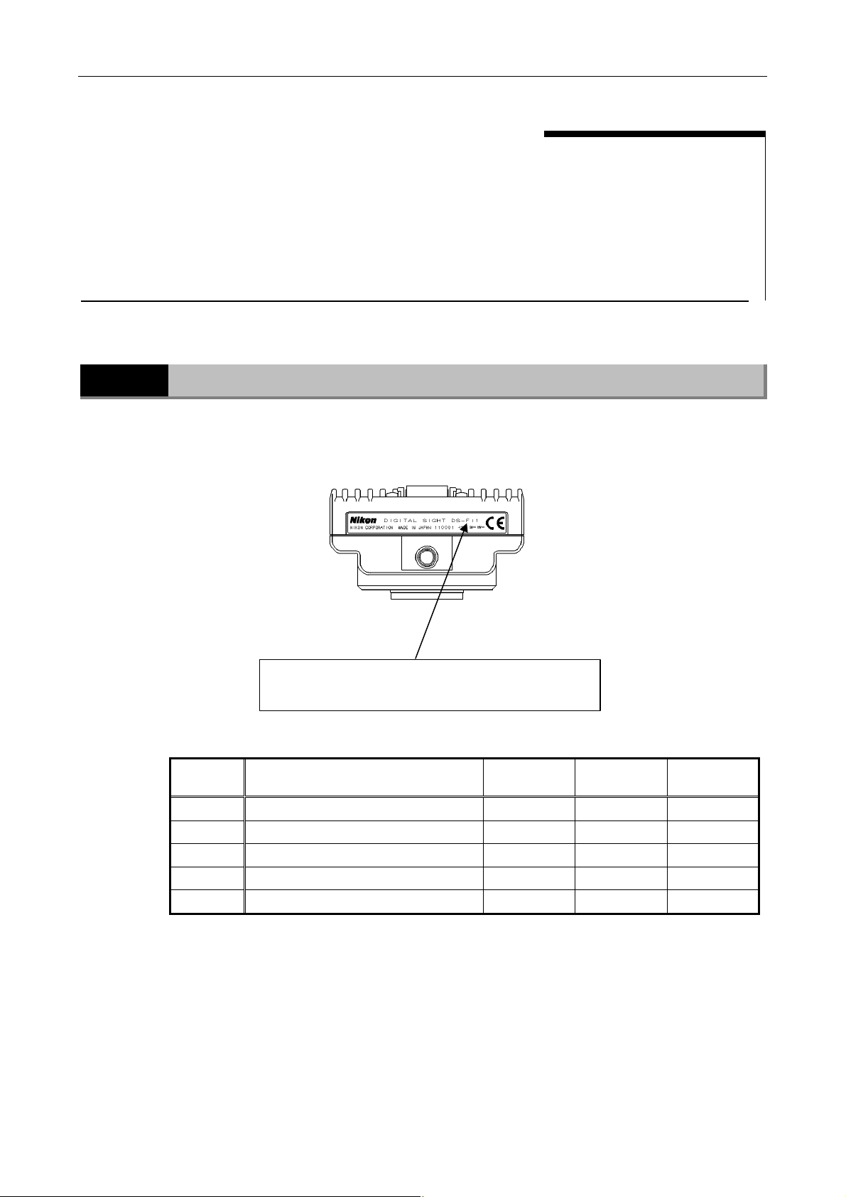
There are five models available for the DS camera head as follows. The features differ depending on the
model you have purchased. Check the model name indicated on the DS camera head before use.
• Features of each model
Model Image pickup device Cooling
Model name is indicated on the tripod mount or a place
near the location for the camera cap attachment.
Pixel- shifting
function
Body color
DS-Fi1 2/3-inch, color, 5.24-megapixel ―― ―― White
DS-Vi1 1/1.8-inch, color, 2.11-megapixel ―― ―― White
DS-Qi1Mc 2/3-inch, monochrome, 1.50-megapixel Applied ―― Black
DS-Fi1c 2/3-inch, color, 5.24-megapixel Applied ―― Black
DS-Ri1 2/3-inch, color, 1.50-megapixel Applied Applied Black
* For details of the features above, refer to Chapter 9, “Specifications”.
* Pixel-shifting is a high-resolution photographing function available by using NIS-Elements or
other software on a PC connected with IEEE1394b cable.
- 1 -
Chapter 1 Before Use
2 Components
2
1 DS-U3 DS Camera Control Unit
Components
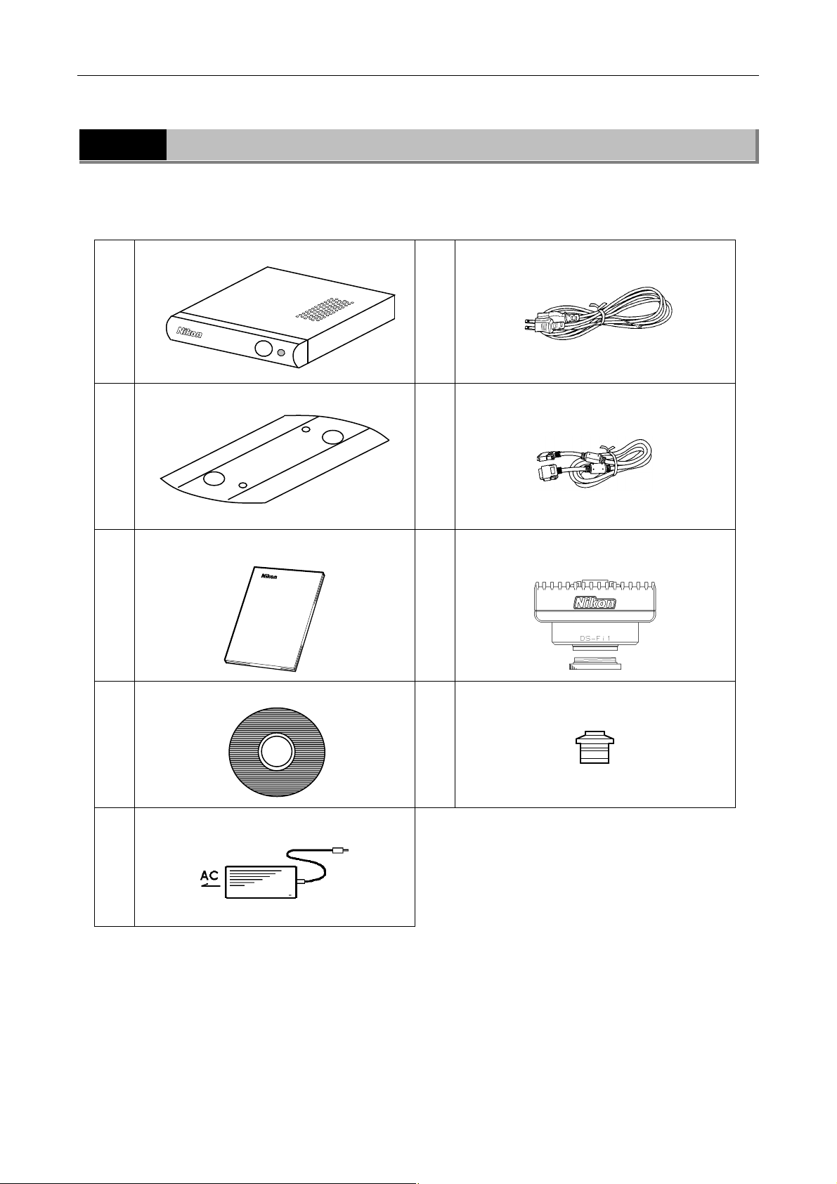
Check that all items listed below are provided in the package.
If any items are missing, contact your nearest Nikon representative immediately.
2 Vertical stand
3 Instruction manual
6 Power cord
7 DS camera cable (DS Camera I/F cable
20-26; 3 m)
8 DS Camera Head with a C mount cap
4 NIS-Elements freeware package (CD-ROM)
5 AC adapter
9 C mount adapter (optional)
- 2 -

Chapter 2 Peripheral Equipment
2
Peripheral Equipment
(1) PC
The DS-U3 is designed for use with a PC connected via an IEEE1394b (bilingual) interface. The
DS-U3 performs the following operations via NIS-Elements freeware installed on a PC.
1) Display captured images on the PC monitor
2) Confirm/change the setting (for photographing conditions, etc.) of the DS-U3
Additionally, using the Nikon NIS-Elements software (optional) enables advanced measurement
and analysis.
Contact your nearest Nikon representative for the NIS-Elements software. For details on control
function, refer to the manual provided with the software.
The PC and its monitor to be connected to the DS-U3 must meet the following system
requirements.
• PC unit
Item Requirements
Type Windows PC
CPU Equivalent to Xeon 2.6 GHz or higher
Memory 2 GB or more
Hard disc 100 MB of free hard disk space for installation; 300 MB of free disk space for
program execution
Video 1280 x 1024 pixels, High Color mode or better (True Color mode recommended)
OS Windows 7/Windows XP (Japanese/English)
Note) Use Windows 7 Professional/Windows XP Professional Service Pack 2.
IEEE1394b IEEE1394b FireWire PCle Card (NK653AA from Hewlett Packard recommended)
For installation of the IEEE1394b PCI board, refer to the instruction manuals of the PC and the
IEEE1394b PCI board.
• PC monitor
Item Requirement
Resolution 1280 x 1024 pixels, True Color mode displayable monitor recommended
It is not guaranteed that the software runs on all PCs that comply with the operating environments
described above. For more details, contact your nearest Nikon representative.
- 3 -

(2) IEEE1394b cable
IEEE1394b cable is used to connect the DS-U3 to the PC. We recommend a cable provided with
the IEEE1394b FireWire PCIe Card.
(3) C mount lens
The C mount lens is required to photograph subjects other than photomicrographs. Any lens that
meets the following conditions may be used:
• Protrudes no more than 10 mm from the mount surface into the camera.
• The image circle of the DS-Vi1 is 1/1.8”, and that of the DS-Fi1, DS-Fi1c, DS-Qi1Mc or
• When using diaphragm settings brighter than F2.8, you may observe slight light fall off
Chapter 2 Peripheral Equipment
Less than 5 mm for DS-Ri1.
DS-Ri1 is 2/3”. Use a lens for 1” or 2/3”.
around the periphery.
- 4 -
Chapter 3 Names of Parts and Their Functions
V
V
1 DS-U3 DS Camera Control Unit
3
Names of Parts and Their Functions
1
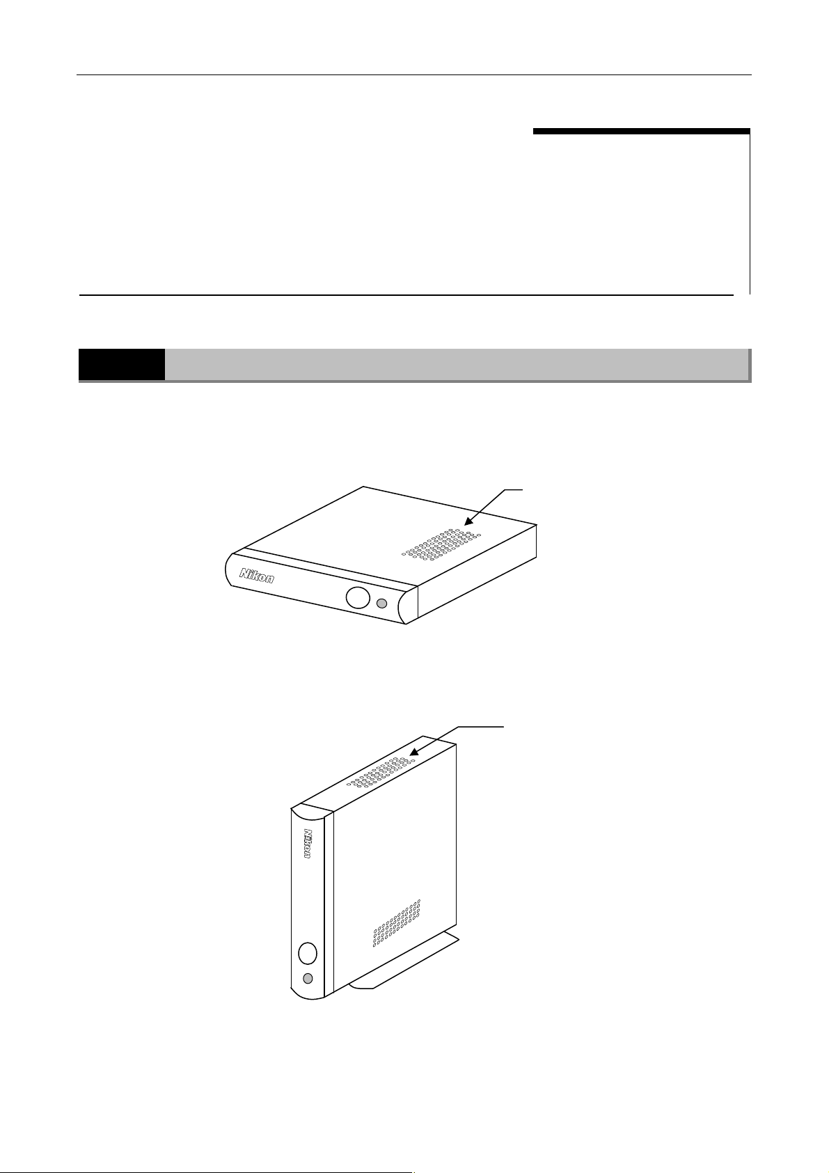
(1) External appearance of the DS-U3
DS-U3 DS Camera Control Unit
entilation hole (on the top)
For internal cooling.
- 5 -
entilation hole (on the left)
For internal cooling.
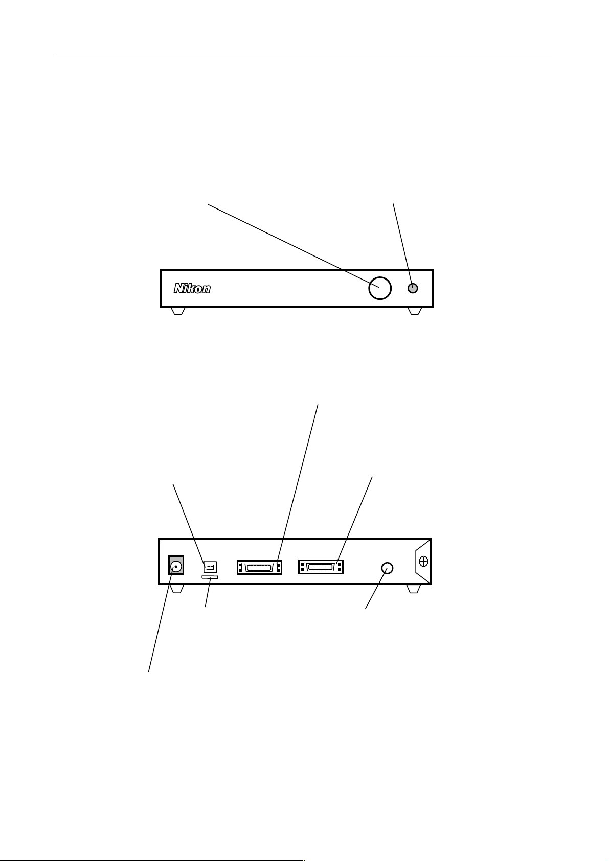
(2) Front of the DS-U3
r
A
r
r
X
r
Power switch
This is a push switch. Press to
turn it on. Press again to release
and turn it off. When the power is
on, the power indicator lights up.
Chapter 3 Names of Parts and Their Functions
1 DS-U3 DS Camera Control Unit
Power indicato
When power is turned on, the indicator
first flashes green, and then turns to
green. When the indicator lights up in
green, the DS-U3 is ready for operation.
(3) Rear of the DS-U3
IEEE1394 connector
Connects to a PC via an IEEE
1394b cable.
DC IN 12V IEEE1394 CAMERA1 CAMERA2 EXT.I/O
Holde
Keeps the cable from being
pulled off the lEEE1394
connector.
DC lN 12V connecto
Use the supplied AC adapter.
MERA 1 connecto
C
Connects to the DS camera head.
* Be sure to turn off power before
connecting or disconnecting the
connector: otherwise, the equipment
malfunctions.
CAMERA 2 connector
Connects to the DS camera head.
* Be sure to turn off power before
connecting or disconnecting the
connector: otherwise, the equipment
malfunctions.
T. l/O connector
E
When the DS-Qi1Mc is connected,
image capture can be externally
triggered by supplying external trigger
signals from this port.
(Cannot be used unless DS-Qi1Mc is
connected.)
- 6 -

Chapter 3 Names of Parts and Their Functions
r
2 DS Camera Head
2
DS Camera Head
Tripod mount
Mounts the DS camera head on a tripod, etc.
Top
Bottom Rear
C mount cap
Protects the C mount
from dusts.
C mount
When taking microphotographs, mount the C
mount adapter here before connecting to the
microscope.
When taking other photographs, attach the C
mount lens here.
CAMERA OUT connecto
- 7 -
 Loading...