

Page 1

Digital
Videocassette
Recorder
3-619-326-12 (1)
Operating Instructions
Before operating the unit, please read this manual
thoroughly and retain it for future reference.
DSR-1500A/1500AP
© 2002 Sony Corporation
Page 2
Owner’s Record
The model and serial numbers are located at the bottom.
Record these numbers in the spaces provided below. Refer
to them whenever you call upon your Sony dealer
regarding this product.
This symbol is intended to alert the user to
the presence of uninsulated “dangerous
voltage” within the product’s enclosure
that may be of sufficient magnitude to
constitute a risk of electric shock to
persons.
Model No.
Serial No.
WARNING
To prevent fire or shock hazard, do not
expose the unit to rain or moisture.
To avoid electrical shock, do not open the
cabinet. Refer servicing to qualified
personnel only.
THIS APPARATUS MUST BE EARTHED.
CAUTION
The apparatus shall not be exposed to dripping or
splashing and no objects filled with liquid, such as vases,
shall be placed on the apparatus.
The unit is not disconnected from the AC power source
(mains) as long as it is connected to the wall outlet, even if
the unit itself has been turned off.
IMPORTANT
The nameplate is located on the bottom.
This symbol is intended to alert the user to
the presence of important operating and
maintenance (servicing) instructions in
the literature accompanying the
appliance.
* The graphical symbols are on the bottom enclosure.
WARNING: THIS WARNING IS APPLICABLE FOR
USA ONLY.
Using this unit at a voltage other than 120 V may require
the use of a different line cord or attachment plug, or both.
To reduce the risk of fire or electric shock, refer servicing
to qualified service personnel.
For customers in the USA (DSR-1500A only)
This equipment has been tested and found to comply with
the limits for a Class A digital device, pursuant to Part 15
of the FCC Rules. These limits are designed to provide
reasonable protection against harmful interference when
the equipment is operated in a commercial environment.
This equipment generates, uses, and can radiate radio
frequency energy and, if not installed and used in
accordance with the instruction manual, may cause
harmful interference to radio communications. Operation
of this equipment in a residential area is likely to cause
harmful interference in which case the user will be
required to correct the interference at his own expense.
You are cautioned that any changes or modifications not
expressly approved in this manual could void your
authority to operate this equipment.
The shielded interface cable recommended in this manual
must be used with this equipment in order to comply with
the limits for a digital device pursuant to Subpart B of Part
15 of FCC Rules.
2
Page 3

Important Safety Instructions
• Read these instructions.
• Keep these instructions.
• Heed all warnings.
• Follow all instructions.
• Do not use this apparatus near water.
• Clean only with dry cloth.
• Do not block any ventilation openings.
Install in accordance with the manufacturer’s
instructions.
• Do not install near any heat sources such as radiators,
heat registers, stoves, or other apparatus (including
amplifiers) that produce heat.
• Do not defeat the safety purpose of the polarized or
grounding-type plug. A polarized plug has two blades
with one wider than the other. A grounding-type plug
has two blades and a third grounding prong. The wide
blade or the third prong are provided for your safety. If
the provided plug dose not fit into your outlet, consult an
electrician for replacement of the obsolete outlet.
• Protect the power cord from being walked on or pinched
particularly at plugs, convenience receptacles, and the
point where they exit from the apparatus.
• Only use attachments/accessories specified by the
manufacturer.
• Use only with the cart, stand, tripod, bracket, or table
specified by the manufacturer, or sold with the
apparatus.
When a cart is used, use caution when moving the cart/
apparatus combination to avoid injury from tip-over.
• Unplug this apparatus during lightning storms or when
unused for long periods of time.
• Refer all servicing to qualified service personnel.
Servicing is required when the apparatus has been
damaged in any way, such as power-supply cord or plug
is damaged, liquid has been spilled or objects have fallen
into the apparatus, the apparatus has been exposed to
rain or moisture, does not operate normally, or has been
dropped.
Caution
Television programs, films, video tapes and other
materials may be copyrighted.
Unauthorized recording of such material may be contrary
to the provisions of the copyright laws.
For customers in Europe (DSR-1500AP only)
This product with the CE marking complies with both the
EMC Directive (89/336/EEC) and the Low Voltage
Directive (73/23/EEC) issued by the Commission of the
European Community.
Compliance with these directives implies conformity to
the following European standards:
• EN60065: Product Safety
• EN55103-1: Electromagnetic Interference (Emission)
• EN55103-2: Electromagnetic Susceptibility (Immunity)
This product is intended for use in the following
Electromagnetic Environment(s):
E1 (residential), E2 (commercial and light industrial), E3
(urban outdoors) and E4 (controlled EMC environment,
ex. TV studio).
Voor de Klanten in Nederland
• Dit apparaat bevat een vast ingebouwde batterij die niet
vervangen hoeft te worden tijdens de levensduur van het
apparaat.
• Raadpleeg uw leverancier indien de batterij toch
vervangen moet worden.
De batterij mag alleen vervangen worden door
vakbekwaam servicepersoneel.
• Gooi de batterij niet weg maar lever deze in als klein
chemisch afval (KCA).
• Lever het apparaat aan het einde van de levensduur in
voor recycling, de batterij zal dan op correcte wijze
verwerkt worden.
3
Page 4

Table of Contents
Chapter 1 Overview
Features.................................................................................6
DVCAM Format ....................................................................... 6
Variety of Interfaces.................................................................. 7
Compact Size ............................................................................ 7
Facilities for High-Efficiency Editing....................................... 7
Other Features ........................................................................... 8
Optional Accessories................................................................. 8
Location and Function of Parts........................................... 9
Front Panel ................................................................................ 9
Rear Panel ............................................................................... 19
Chapter 2 Recording and Playback
Usable Cassettes................................................................23
Inserting and Ejecting Cassettes ............................................. 25
Recording............................................................................27
Settings for Recording ............................................................ 28
Recording Procedure............................................................... 30
Playback ..............................................................................34
Settings for Playback .............................................................. 34
Playback Procedure................................................................. 35
Repeat Playback—Automatic Cyclical Playback ................... 37
Setting Points A and B for Repeat Playback........................... 37
Cuing Up to Any Desired Position Set as Point A or B.......... 43
Chapter 3 Convenient Functions for Editing Operation
Setting the Time Data.........................................................44
Displaying Time Data and Operation Mode Indications ........ 44
Using the Internal Time Code Generator................................ 46
Synchronizing Internal and External Time Codes .................. 47
Rerecording the Time Code—TC Insert Function.................. 48
High-Speed and Low-Speed Search—Quickly and
Accurately Determining Editing Points ..................... 51
Search Operations via External Equipment ............................ 51
Digitally Dubbing Signals in DVCAM/DV Format............. 52
Chapter 4 Menu Settings
Menu Organization ............................................................. 56
Menu Contents....................................................................59
Setup Menu ............................................................................. 59
Table of Contents
4
Page 5

Auto Mode (AUTO FUNCTION) Execution Menu............... 72
Changing Menu Settings ...................................................73
Buttons Used to Change Settings............................................ 73
Changing the Settings of Basic Items ..................................... 73
Displaying Enhanced Items .................................................... 75
Changing the Settings of Enhanced Items .............................. 75
Returning Menu Settings to Their Factory Default Settings... 76
Displaying Supplementary Status Information................ 77
Chapter 5 Connections and Settings
Connections for a Digital Non-Linear Editing System .... 79
Connections for a Cut Editing System .............................81
Connections for an A/B Roll Editing System...................83
Connections for SDTI (QSDI) Dubbing .............................90
Connections for Analog Recording ..................................91
Adjusting the Sync and Subcarrier Phases..................... 93
Chapter 6 Maintenance and Troubleshooting
Appendixes
Maintenance........................................................................95
Condensation........................................................................... 95
Regular Checks ....................................................................... 95
Head Cleaning......................................................................... 97
Troubleshooting ................................................................. 98
Error Messages...................................................................... 100
Alarm Messages.................................................................... 100
Precautions .......................................................................103
Specifications ...................................................................104
Glossary ............................................................................107
Index ..................................................................................109
Table of Contents
5
Page 6

Overview
Features
The DSR-1500A/1500AP is a 1/4-inch digital
videocassette recorder using the DVCAM™ digital
recording format.
The unit is equipped with an i.LINK/DV* interface as
standard, so that it can be used as a low-cost, compact
feeder, player or viewer in a non-linear editing system**
without requiring any optional boards. When using the unit
as an editor, the optional boards available for the unit allow
you to select required input signal formats.
The unit is playback-compatible with tapes recorded in DV
format (excluding tapes recorded in LP mode) as well as
DVCPRO (25 Mbps) format. Playing back such tapes on
the unit does not require any adapter.
These and other features of the unit make it suitable for use
under diversified conditions. It can be used, for example,
for desk-top editing or for such applications as electronic
news gathering (ENG) and non-linear editing aboard
outside broadcast vans, at production houses or at
broadcasting stations.
* i.LINK and are trademarks and indicate that this product is in agreement
with IEEE1394-1995 specifications and their revisions.
** Non-linear editing: This is an editing method that uses video and audio
signals digitally encoded and recorded on a hard disk as digital data. When
compared with conventional (linear) editing methods, non-linear editing
offers vastly improved efficiency in editing operations, for example, by
eliminating tape transport time.
The following are the principal features of the unit.
DVCAM Format
DVCAM is a professional 1/4-inch digital recording format
developed by Sony from the consumer DV component
digital format.
Chapter 1
High picture quality and high stability
Video signals are separated into color difference signals
and luminance signals, which are encoded and compressed
to one-fifth size before being recorded to ensure stable and
superb picture quality.
Because the recording is digital, multi-generation dubbing
can be performed with virtually no deterioration of quality.
Wide track
The recording track width is 15 µm, 50% wider than the 10
µm of the DV format. This ensures adequate reliability for
professional use.
High-quality PCM digital audio
PCM recording makes for a wide dynamic range and a
high signal-to-noise ratio, thereby enhancing sound
quality.
There are two recording modes: 2-channel mode (48-kHz
sampling and 16-bit quantization), which offers sound
quality equivalent to the DAT (Digital Audio Tape)
format, or 4-channel mode (32-kHz sampling and 12-bit
quantization).
Superior playback compatibility with DV
and DVCPRO (25 Mbps) formats
Tapes recorded in DV format (excluding the tapes
recorded in LP mode) as well as DVCPRO (25 Mbps)
format can be played back on this unit without requiring a
cassette adapter. You can use the recordings on such tapes
as source material for editing, applying such functions as
the jog audio and digital slow-motion playback as
required. Using the material, editing can be carried out to
single-frame precision.
The unit can also be used for recording in DV format (in
SP mode only).
6
Features
Page 7

Note
When playing back a tape recorded in DVCPRO (25
Mbps) format, the outputs in SDTI format of this unit are
muted. Furthermore, it is not possible to playback the cueaudio track of the tape.
Support for three cassette sizes
There are two sizes of DVCAM cassette: standard and
mini. You can use either size with this unit.
The unit also accepts L and M sizes of DVCPRO cassette.
• When a cassette is inserted, the reel mechanism of the
unit automatically adjusts to the size of the inserted
cassette.
• The capacity of a standard cassette is 184 minutes of
recording/playback, and that of a mini cassette is 40
minutes. When DV (SP) format is used, these recording/
playback times are extended to 276 minutes and 60
minutes, respectively.
Variety of Interfaces
selected with front panel buttons for input and menu
items for output.
• Analog audio: The unit has two audio channels. When
in 4-channel mode, you can input two channels of audio
either as channels 1 and 2 or as channels 3 and 4. The two
audio channels can be output also either as channels 1
and 2 or as channels 3 and 4.
The analog output interfaces are provided as standard so
that the unit can readily be used as a viewer, for example,
at broadcasting stations and aboard outside broadcast vans
without requiring any optional boards.
Inputting analog video and audio signals requires the
optional DSBK-1505 Analog Input Board.
Compact Size
The compact size of the unit makes the unit suitable for use
as a desk-top editor or feeder machine for non-linear
editing or as a viewer compatible with a full range of
digital and analog signal formats aboard an outside
broadcast van.
Chapter 1 Overview
Digital interfaces
The following optional digital interfaces can be used with
the unit.
• i.LINK (DV): The unit’s i.LINK/DV IN/OUT
connector can input and output digital video and audio
signals in DV format.
• SDTI (QSDI)* (optional DSBK-1501 Digital Input/
Output Board): When the unit is fitted with the optional
DSBK-1501 board, SDTI (QSDI)-format video, audio
and time code signals can be transferred between the unit
and the Sony EditStation at normal speed. When this unit
is connected to another DVCAM VCR, it is possible to
copy compressed signals between the two VCRs.
(You cannot use the SDTI (QSDI) and SDI (see next
paragraph) interfaces at the same time. You can select
either of the two using front panel buttons for input or
with a menu item for output.)
• SDI (serial digital interface)/AES/EBU (optional
DSBK-1501 Digital Input/Output Board): When the
unit is fitted with the optional DSBK-1501 board, it can
input and output D1 (component) format digital video
and audio signals and also AES/EBU-format digital
audio signals.
* SDTI is the name of a standard interface established as SMPTE 305M.
QSDI is a type of SDTI. This unit uses SDTI to transmit DV data, and the
input/output connectors are labeled “SDTI (QSDI).”
Facilities for High-Efficiency Editing
Digital slow motion playback
Using the frame memory function, noiseless slow motion
playback is possible at any speed in the range ±0.5 times*
normal speed.
* The positive direction refers to forward movement of the tape, and the
negative direction to reverse movement.
Digital jog sound function
When searching at speeds in the range ±0.5 times normal
speed, the digital jog sound function is enabled. The audio
signal is saved in temporary memory, and replayed
according to the search speed. This allows searching on the
sound track.
Remote control
The unit can be operated by remote control from an editing
control unit that supports the RS-422A interface or an
optional SIRCS*-compatible remote control unit such as
the DSRM-10.
* SIRCS (Sony Integrated Remote Control System): A command protocol
to remote control Sony professional videocassette recorders/players.
Analog interfaces
The unit can also use the following analog interfaces.
• Analog video: These interfaces include a component
interface, composite interface, and S-video interface.
The same BNC type input and output connectors are
used to input and output signals in different formats
High-speed search function
You can carry out color picture searches during fast
forward and rewind at speeds up to 85 times normal speed.
When remote-controlling this unit in shuttle mode from an
editing control unit or a remote control unit, you can search
at any speed in the range 0 (still) to 60 times normal speed
Features
7
Page 8

in both directions. You can also search frame-by-frame in
jog mode.
At search speeds up to 10 times normal speed in both
directions, you can also hear playback audio.
Quick mechanical response
When you use the tape transport buttons of the unit, the
tape inserted in the unit responds quickly.
Chapter 1 Overview
Superimposition function
Time code values, operation mode indications, error
messages, and other text data can be superimposed and
output in analog composite video signals.
Other Features
Menu system for functionality and
operation settings
The video test signal generator can produce either a color
bar signal or a black burst signal. The audio test signal
generator can generate either a silent signal or a 1-kHz sine
wave signal. Menu items are provided for selecting the test
signals to be generated.
Video process control
For analog video output and SDI-format video output, you
can use menu items to adjust the video output level,
chroma signal output level, setup level (for DSR-1500A),
black level (for DSR-1500AP), and chroma phase.
Reference signal connection
The reference video input connector of the unit is provided
with a loop-through connector which can be used to
connect the input reference video signal to other
equipment. When there is no loop-through connection, the
reference video input connector is automatically provided
with a 75-ohm termination.
The unit provides a menu system to make its various
functions easier to use and set up its operation conditions.
Easy maintenance functions
Self-diagnostic/alarm function: This function
automatically detects setup and connection errors,
operation faults, and other problems. It also displays a
description of the problem, its cause, and the
recommended response on the video monitor screen or
time counter display.
Digital hours meter: The digital hours meter functions
include four kinds of tally operations for operating
hours, head drum usage hours, tape transport hours,
and tape threading/unthreading times. The tally results
can be viewed on the video monitor or the time counter
display.
AC operations
The unit operates with an AC power source in the range
100 to 240 V, 50/60 Hz.
Internal and external time codes
An internal time code generator and reader enables time
code compliant with SMPTE (for DSR-1500A)/EBU
(DSR-1500AP) format to be recorded and played back.
This allows editing to single frame precision.
Outputting or inputting time code (LTC) to or from an
external device is also possible using the TC IN/OUT
connectors.
The unit is also compatible with VITC.
Closed caption compatibility
Whether or not to include closed captions in a recording
can be determined with menu items (for DSR-1500A
only).
Optional Accessories
DSBK-1501 Digital Input/Output Board
This interface enables digital video and audio signals in the
SDI or SDTI (QSDI) format (either format to be selected
with front panel buttons for input or with a menu item for
output) and also AES/EBU-format digital audio signals to
be transferred between this unit and digital Betacam VCRs
or other digital equipment.
DSBK-1505 Analog Input Board
When this interface is installed, the unit can input analog
video and audio signals. The same BNC type input
connectors are used to input analog video signals in
different formats selected with front panel buttons.
The analog video signals that can be input are as follows.
• Composite video signals
• S-video signals
• Component video signals (Y, R
−Y and B−Y)
Internal test signal generator
The unit has built-in video and audio test signal generators.
Features
8
Page 9
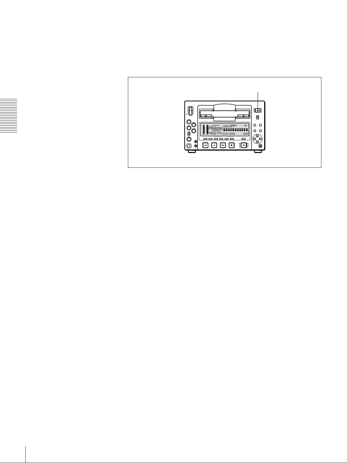
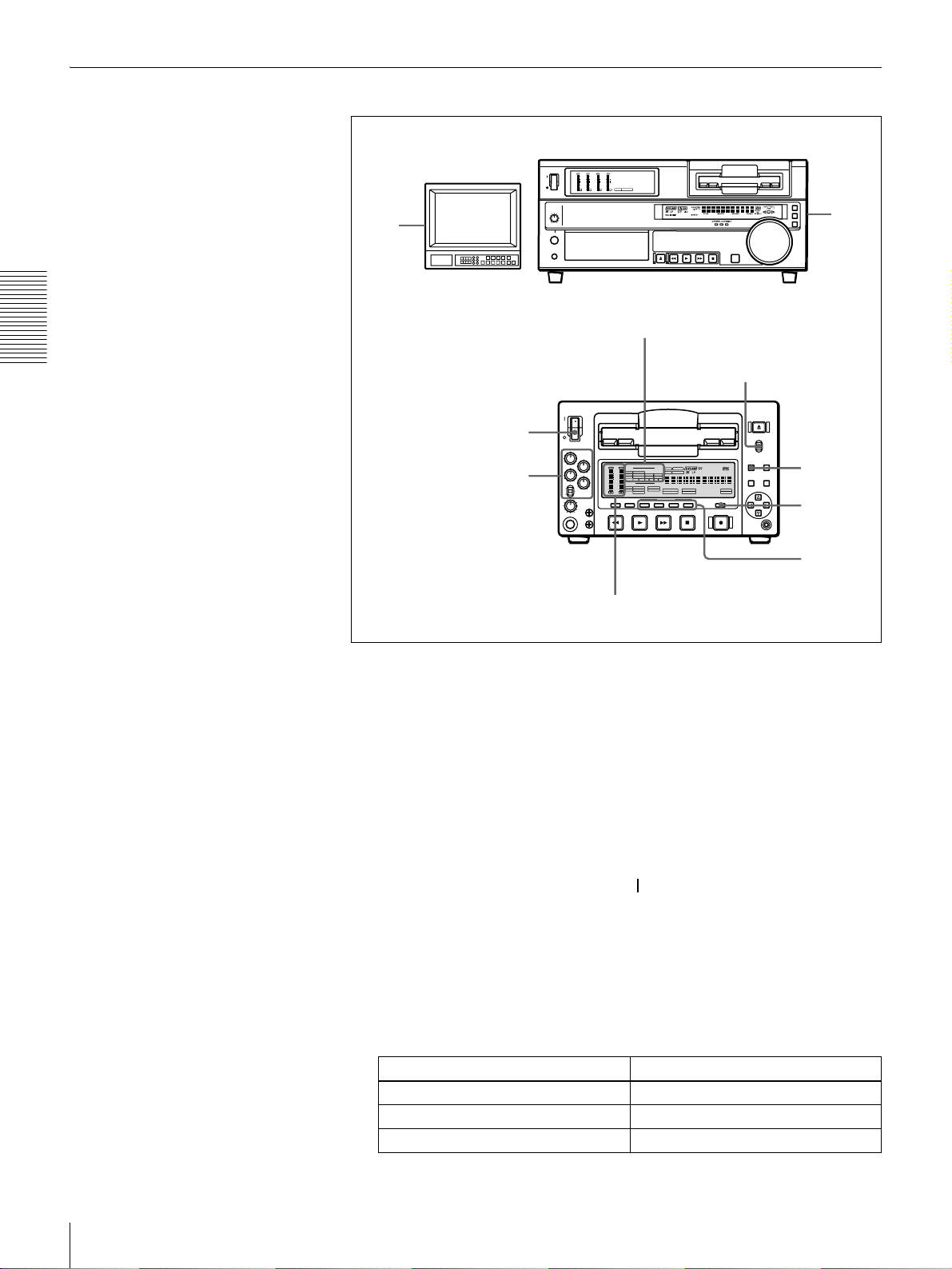
Location and Function of Parts
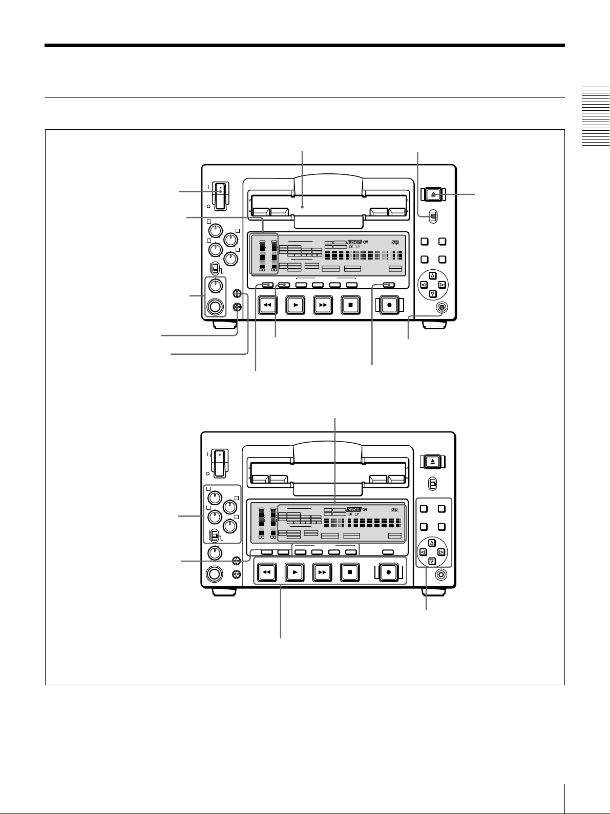
Front Panel
a POWER switch
b Audio level meters
c PHONES connec tor
and control knob
d SC control
e SYNC control
VAR
REC
PB
POWER
1
3
PHONES
f Cassette compartment
REC/PB
LEVEL
2
OVER
OVER
dB
dB
INPUT
0
PRESET
0
-12
4
-20
-30
-40
-60
CH-
SYNC
SC
VIDEO
V:SDTI
COMPOSITE
SDTI
S VIDEO
-12
i.LINK
Y-R,B
-20
SDI SG
OUTPUT
-30
VIDEO
-40
SDI
COMPOSITE
-60
SDTI
S VIDEO
CH-
2 4
1 3
Y-R,B
MONITOR
METER
SELECT
CH-1/2 3/4 SDTI/i.LINK VIDEO
REW PLAY F FWD STOP
j METER CH-1/2 3/4
button
i MONITOR SELECT button
REC MODE
2CH 4CH
VITC
EDIT MODE
REC INHI
COUNTER
SELECT
SERVO
U-BIT
AUDIO
CH-1 1/2
CH-2 3/4
TC NOCLEDIT
ANALOG
ANALOG
AES/EBU
AES/EBU
SDI SG SDI SG
AUDIO
HOURS MINUTES SECONDS FRAMES
CH 1/2
CH 3/4
PB FS
48K 44.1K 32K
INPUT SELECT
CH1 1/2 CH2 3/4
REC
k COUNTER SELECT button
C Display section (see page 14)
g LOCAL/REMOTE switch
EJECT
LOCAL
REMOTE
MENU RESET(NO)
REPEATCOUNTER
REMOTE
9P i.LINK
TC
PRESET
CONTROL S
SET(YES)
l CONTROL S connector
Chapter 1 Overview
h EJECT button
A Audio input/output level
control section (see
page 11)
B Video/audio input setting
section (see page 12)
VAR
REC
PB
POWER
1
3
PHONES
REC/PB
LEVEL
PRESET
2
OVER
OVER
dB
dB
INPUT
0
0
V:SDTI
SDTI
-12
-12
4
SYNC
SC
i.LINK
-20
-20
OUTPUT
-30
-30
-40
-40
SDI
-60
-60
SDTI
CH-
CH-
2 4
1 3
MONITOR
METER
SELECT
CH-1/2 3/4 SDTI/i.LINK VIDEO
REW PLAY F FWD STOP
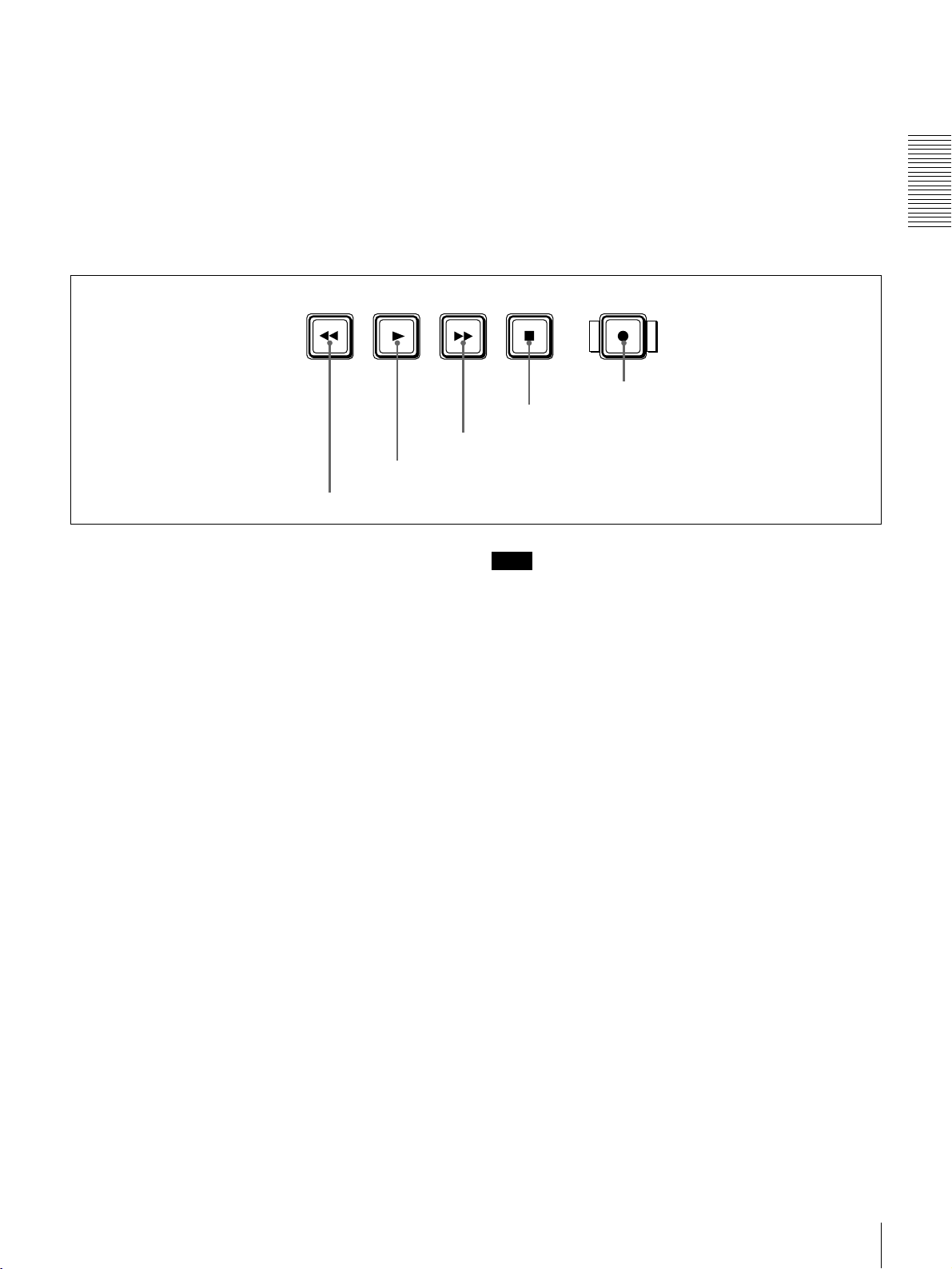
D Tape transport control
section (see page 17)
VIDEO
COMPOSITE
S VIDEO
Y-R,B
SDI SG
VIDEO
COMPOSITE
S VIDEO
Y-R,B
U-BIT
SERVO
AUDIO
CH-1 1/2
CH-2 3/4
TC NOCLEDIT
ANALOG
ANALOG
AES/EBU
AES/EBU
SDI SG SDI SG
AUDIO
HOURS MINUTES SECONDS FRAMES
CH 1/2
CH 3/4
PB FS
REC MODE
48K 44.1K 32K
2CH 4CH
INPUT SELECT
CH1 1/2 CH2 3/4
VITC
EDIT MODE
REC INHI
COUNTER
SELECT
REC
REPEATCOUNTER
REMOTE
9P i.LINK
EJECT
LOCAL
REMOTE
MENU RESET(NO)
TC
SET(YES)
PRESET
CONTROL S
E Menu control section
(see page 18)
Location and Function of Parts
9
Page 10

a POWER switch
Press the “ ” side to power on the unit. This causes the
audio level meters and the display section to light. To
power off the unit, press the “ ” side of the switch.
b Audio level meters
These two meters indicate the recording audio levels
during recording or EE mode* and the playback audio
levels during playback. When the audio level indicated on
Chapter 1 Overview
a meter exceeds 0 dB, the OVER indicator for the meter
lights.
The short bars to the right of level indication bars indicate
that those levels are reference audio recording levels.
The settings made with the METER CH-1/2 3/4 button and
MONITOR SELECT button select the audio channels for
level indications on these meters as follows.
When CH-1/2 mode is selected with the METER CH-1/
2 3/4 button:
Every time the MONITOR SELECT button is pressed,
the audio channel selection for level indications on the
two meters cycles through the following options.
• CH-1 (channel 1) only
Only the CH-1 indicator lights.
• CH-2 (channel 2) only
Only the CH-2 indicator lights.
• CH-1 and CH-2 (channels 1 and 2)
Both the CH-1 and CH-2 indicators light.
When CH-3/4 mode is selected with the METER CH-1/
2 3/4 button:
Every time the MONITOR SELECT button is pressed,
the audio channel selection for level indications on the
two meters cycles through the following options.
• CH-3 (channel 3) only
Only the CH-3 indicator lights.
• CH-4 (channel 4) only
Only the CH-4 indicator lights.
• CH-3 and CH-4 (channels 3 and 4)
Both the CH-3 and CH-4 indicators light.
* E-E mode: Abbreviation of “Electric-to-Electric mode.” In this mode,
video and audio signals input to the VCR are output after passing through
internal electric circuits, but not through magnetic conversion circuits such
as heads and tapes. This can be used to check input signals and for
adjusting input signal levels.
c PHONES connector (stereo phone jack) and
control knob
Connect stereo headphones to the connector for audio
monitoring during recording or playback. The control
knob controls the volume of the headphones. It also
controls the level of the audio signal output from the
MONITOR connector on the rear panel.
The settings made with the METER CH-1/2 3/4 button and
MONITOR SELECT button select the audio channels for
audio output via this connector. The same channel
selection as for the audio level meters applies to this
connector.
d SC (subcarrier phase) control
Turn this control to accurately adjust the subcarrier phase
of the composite video output signal of the unit with
respect to the reference video signal. Use a cross-point
(Phillips) screwdriver to turn it.
e SYNC (synchronization phase) control
Turn this control to accurately adjust the synchronization
phase of the output video signal of the unit with respect to
the reference video signal. Use a cross-point (Phillips)
screwdriver to turn it.
f Cassette compartment
Accepts DVCAM, DV and DVCPRO (25 Mbps)
videocassettes.
For details of usable cassettes, see page 23.
g LOCAL/REMOTE switch
Selects whether the unit is operated from its front panel or
from external equipment.
LOCAL: The unit is operated from its front panel or from
a SIRCS-compatible remote control unit connected to
the CONTROL S connector on the front panel.
REMOTE: The unit is operated from external equipment
connected to the REMOTE connector or DV IN/
OUT connector on the rear panel.
Note
When you edit using the DV IN/OUT connector,
with video and audio signal input set to “i.LINK” and
remote control set to “9PIN”, the locations where edit
points are actually set may not be the same as the
specified locations.
When you set video and audio signal input to
“i.LINK”, set remote control to “i.LINK” as well.
h EJECT button
When you press this button, the cassette is automatically
ejected after a few seconds.
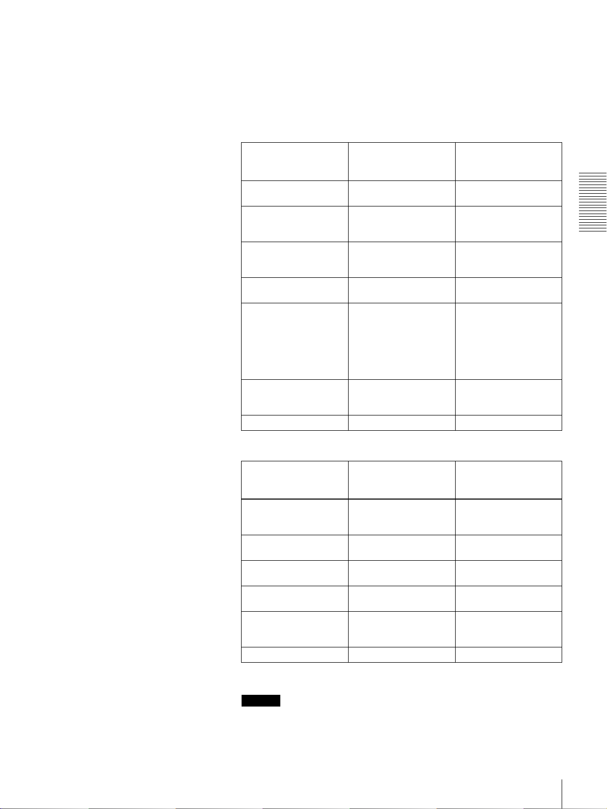
i MONITOR SELECT button
Use this button and the METER CH-1/2 3/4 button to
select the audio channels:
• for level indications on the audio level meters
• for audio output via the PHONES connector on the front
panel
• for audio output via the MONITOR connector on the
rear panel
Depending on the setting made with the METER CH-1/2
3/4 button, the channels for output to the above meters and
connectors are selected as follows.
Location and Function of Parts
10
Page 11
When CH-1/2 mode is selected with the METER CH-1/
2 3/4 button:
Audio level meters PHONES
connector
CH-1 (channel 1) only.
Only the left meter lights.
CH-2 (channel 2) only.
Only the right meter
lights.
CH-1 and CH-2 (channels
1 and 2).
Both the left and right
meters light.
Channel 1 only
(monaural)
Channel 2 only
(monaural)
Channels 1
and 2 (stereo)
MONITOR
connector
Channel 1 only
Channel 2 only
Channels 1
and 2 (mixed)
When CH-3/4 mode is selected with the METER CH-1/
2 3/4 button:
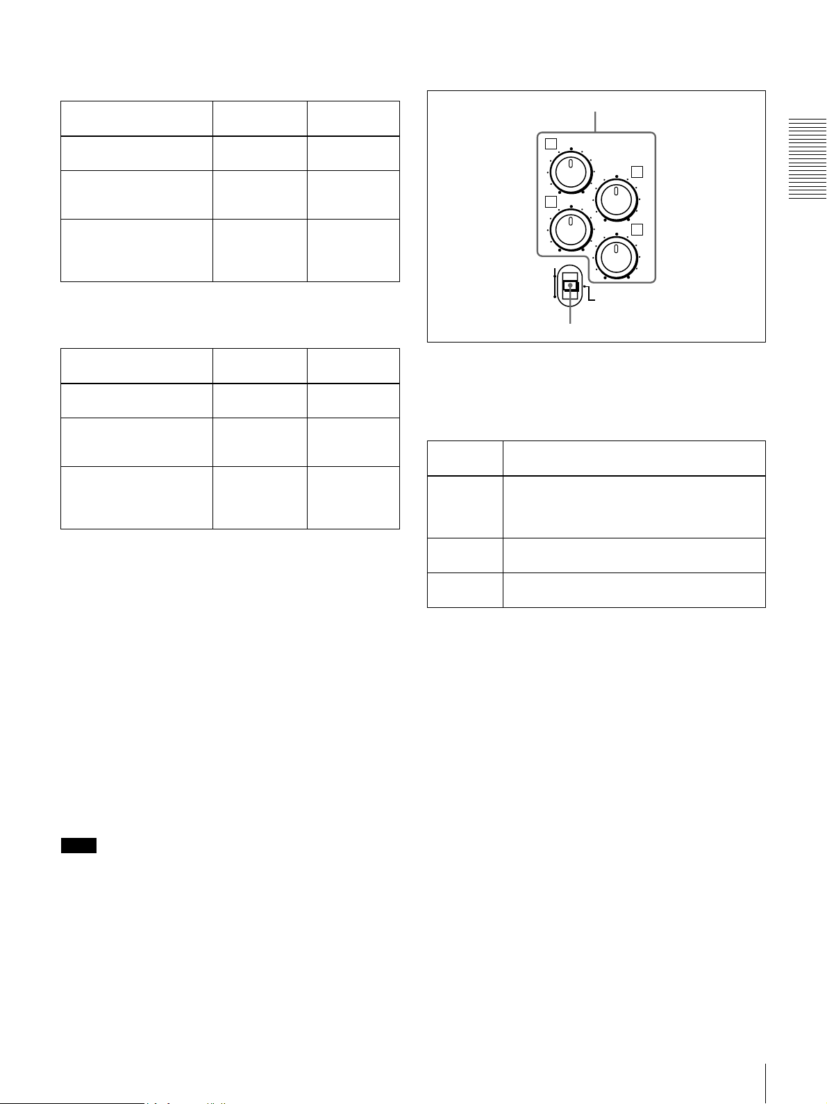
A Audio input/output level control section
a REC/PB LEVEL control knobs
1
3
VAR
REC
PB
REC/PB
LEVEL
PRESET
b VAR switch
2
4
Chapter 1 Overview
Audio level meters PHONES
CH-3 (channel 3) only.
Only the left meter lights.
CH-4 (channel 4) only.
Only the right meter
lights.
CH-3 and CH-4 (channels
3 and 4).
Both the left and right
meters light.
connector
Channel 3 only
(monaural)
Channel 4 only
(monaural)
Channels 3
and 4 (stereo)
MONITOR
connector
Channel 3 only
Channel 4 only
Channels 3
and 4 (mixed)
j METER CH-1/2 3/4 button
Pressing this button toggles the audio level meter mode
between CH-1/2 (channels 1 and 2) and CH-3/4 (channels
3 and 4).
The settings made with this button and the MONITOR
SELECT button select the channels for level indications
and audio output.
For more details, see “i MONITOR SELECT button.”
k COUNTER SELECT button
Selects the type of time data to be shown in the time
counter display. Each press of this button cycles through
the following three indicator display options:
• COUNTER (CNT: count value of the time counter)
• TC (time code)
• U-BIT (user bits)
a REC/PB LEVEL control knobs
These knobs used to control audio levels function
differently depending on the setting of the VAR switch as
follows.
VAR switch
setting
PRESET Control knobs are not effective.
REC Control the analog/digital audio input levels on
PB Control the analog/digital audio output levels
Functions of control knobs
The analog audio input/output levels are set to
the reference level set with the LEVEL
SELECT menu item (see page 67).
channels 1 to 4 during recording.
on channels 1 to 4 during playback.
b VAR switch
Use to switch the way in which the REC/PB LEVEL
control knobs function.
Note
If the LOCAL/REMOTE switch is set to REMOTE, the
COUNTER SELECT button does not operate while the
tape is moving. In this case, make the time data selection
via the external equipment connected to the REMOTE
connector on the rear panel.
l CONTROL S connector (stereo minijack)
Connect a SIRCS-compatible remote control unit such as
the DSRM-10 to this connector.
Location and Function of Parts
11
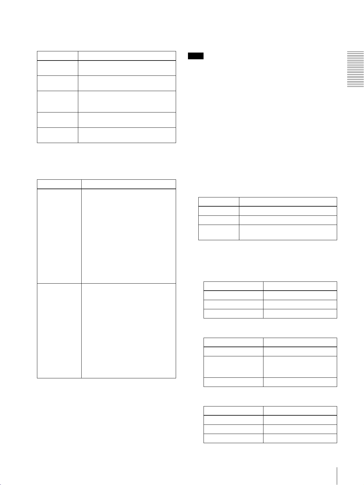
Page 12

B Video/audio input setting section
SDTI/i.LINK VIDEO
Chapter 1 Overview
a SDTI/i.LINK button
a SDTI/i.LINK (SDTI (QSDI) interface/i.LINK
selection) button
Each press of this button cycles through the following
input signal selection options.
• Digital video signal in SDTI (QSDI) format input to the
SDI/SDTI (QSDI) IN connector (optional DSBK-1501
board required)
When this is selected, use the CH1 1/2 button and CH2
3/4 button to select the required input audio signals.
Note
In this case, the phases of the selected audio signals
will be about two frames ahead of the phase of the
digital video signal in SDTI (QSDI) format.
• Digital video and audio signals in SDTI (QSDI) format
input to the SDI/SDTI (QSDI) IN connector (optional
DSBK-1501 board required)
• Digital video and audio signals in i.LINK-compatible
DV format input to the i.DV IN/OUT connector
The selection made with this button is indicated in the
INPUT signal display section (see page 15).
b VIDEO button
Each press of this button cycles through the following
input video signal selection options.
•
Composite video signal input to the VIDEO IN
connector (optional DSBK-1505 board required)
• S-video (separated Y and C) signals input to the VIDEO
IN connectors (optional DSBK-1505 board required)
•Y, R
−Y and B−Y component video signals input to the
VIDEO IN connectors (optional DSBK-1505 board
required)
• SDI video signal input to the SDI/SDTI (QSDI) IN
connector (optional DSBK-1501 board required)
• Video test signal (selected with the INT VIDEO SG
menu item (see page 65)) generated by the internal
signal generator
The selection made with this button is indicated by the
VIDEO indicators in the INPUT signal display section (see
page 14).
INPUT SELECT
b VIDEO button
CH1 1/2 CH2 3/4
c CH1 1/2 button
d CH2 3/4 button
c CH1 1/2 (audio channel 1 or 1/2) button
Each press of this button cycles through the following
input audio signal selection options for audio channel 1
(when in 2-channel mode) or for audio channels 1 and 2
(when in 4-channel mode).
• Analog audio signal input to the AUDIO IN 1/3
connector (optional DSBK-1505 board required)
• Digital audio signal in AES/EBU format input to the
AUDIO (AES/EBU) IN 1/2 connector (optional DSBK1501 board required)
• SDI audio signal input to the SDI/SDTI (QSDI) IN
connector (optional DSBK-1501 board required)
• Audio test signal (selected with the INT AUDIO SG
menu item (see page 67) generated by the internal signal
generator
The selection made with this button is indicated by the
AUDIO CH-1 1/2 indicators in the INPUT signal display
section (see page 14).
When analog audio is selected (optional DSBK-1505
board required), the signal input to the AUDIO IN 1/3
connector is recorded either on channel 1 (when in 2channel mode) or on channels 1 and 3 (when in 4-channel
mode). That is, in 4-channel mode, the same analog audio
signal is recorded on channels 1 and 3. Using the REC/PB
LEVEL control knobs with the VAR switch set to REC, it
is possible to adjust the audio levels on the two channels
separately.
You can switch the audio recording mode with the REC
MODE menu item (see page 66). The selection is indicated
by the REC MODE display on the front panel.
d CH2 3/4 (audio channel 2 or 3/4) button
Each press of this button cycles through the following
input audio signal selection options for audio channel 2
(when in 2-channel mode) or for audio channels 3 and 4
(when in 4-channel mode).
• Analog audio signal input to the AUDIO IN 2/4
connector (optional DSBK-1505 board required)
• Digital audio signal in AES/EBU format input to the
AUDIO (AES/EBU) IN 3/4 connector (optional DSBK1501 board required)
• SDI audio signal input to the SDI/SDTI (QSDI) IN
connector (optional DSBK-1501 board required)
• Audio test signal (selected with the INT AUDIO SG
menu item (see page 67) generated by the internal signal
generator
The selection made with this button is indicated by the
AUDIO CH-2 3/4 indicators in the INPUT signal display
section (see page 14).
When analog audio is selected (optional DSBK-1505
board required), the signal input to the AUDIO IN 2/4
connector is recorded either on channel 2 (when in 2channel mode) or on channels 2 and 4 (when in 4-channel
mode). That is, in 4-channel mode, the same analog audio
signal is recorded on channels 2 and 4. Using the REC/PB
LEVEL control knobs with the VAR switch set to REC, it
Location and Function of Parts
12
Page 13

is possible to adjust the audio levels on the two channels
separately.
You can switch the audio recording mode with the REC
MODE menu item (see page 66). The selection is indicated
by the REC MODE display on the front panel.
Chapter 1 Overview
Location and Function of Parts
13
Page 14

C Display section
Chapter 1 Overview
d Time data type indicators
e SERVO indicator
f Recording/playback tape format indicators
g Cassette memory indicator
INPUT
VIDEO
V:SDTI
COMPOSITE
SDTI
S VIDEO
i.LINK
Y-R,B
SDI SG
OUTPUT
VIDEO
SDI
COMPOSITE
SDTI
S VIDEO
Y-R,B
b OUTPUT signal display section
a INPUT signal display section
U-BIT
TC NOCLEDIT
AUDIO
CH-1 1/2
CH-2 3/4
ANALOG
ANALOG
AES/EBU
AES/EBU
SDI SG SDI SG
AUDIO
CH 1/2
CH 3/4
SERVO
U-BIT
SERVO
TC NOCLEDIT
HOURS MINUTES SECONDS FRAMES
PB FS
48K 44.1K 32K
REC MODE
2CH 4CH
REC INHI
VITC
EDIT MODE
9P i.LINK
c Time counter display
h NO EDIT indicator
i CL indicator
j REC INHI indicator
k Tape end alarm indicator
REC INHI
REPEATCOUNTER
l REPEAT indicator
REPEATCOUNTER
REMOTE
HOURS MINUTES SECONDS FRAMES
PB FS
48K 44.1K 32K
REC MODE
2CH 4CH
o REC MODE display
n PB Fs display
a INPUT signal display section
Indicates the input video and audio signal formats selected
with the INPUT SELECT buttons (SDTI/i.LINK, VIDEO,
CH1 1/2, and CH2 3/4 buttons).
Note
The indicators without the corresponding optional boards
installed in the unit do not light.
Location and Function of Parts
14
VITC
EDIT MODE
REMOTE
9P i.LINK
q VITC indicator
p EDIT MODE indicator
V:SDTI indicator: Lights when the digital video signal
only in SDTI (QSDI) format is selected (optional
DSBK-1501 board required).
SDTI indicator: Lights when the digital video and audio
signals in SDTI (QSDI) format are selected (optional
DSBK-1501 board required).
i.LINK indicator: Lights when the digital video and audio
signals in i.LINK-compatible DV format are selected.
m Remote mode indicators
Page 15
VIDEO indicators: The indicator (COMPOSITE, S
VIDEO, Y
−R,B, SDI, or SG) corresponding to the
selected input video signal format lights.
b OUTPUT signal display section
Indicates the output video and audio signal format selected
with the INTERFACE SELECT menu items (see page 68).
Indicators Meanings
COMPOSITE Composite video signal (optional
DSBK-1505 board required)
S VIDEO S-video (separated Y and C) signals
Y−R,B Y, R−Y and B−Y component video
SDI SDI video signal (optional DSBK-1501
SG Video test signal (factory default
(optional DSBK-1505 board required)
signals (optional DSBK-1505 board
required)
board required)
setting)
AUDIO indicators: Comprise the CH-1 1/2 indicator and
CH-2 3/4 indicator, under each of which there are four
more indicators (ANALOG, AES/EBU, SDI, and SG).
They indicate the selected input audio signal formats.
Indicators Functions
CH-1 1/2
(ANALOG, AES/
EBU, SDI, SG)
CH-2 3/4
(ANALOG, AES/
EBU, SDI, SG)
The indicator corresponding to the
signal format selected for audio input
to channel 1 (when in 2-channel
mode) or to channels 1 and 2 (when
in 4-channel mode) lights.
ANALOG: Analog audio signal
(optional DSBK-1505 board
required)
AES/EBU: Digital audio signal in
AES/EBU format (optional
DSBK-1501 board required)
SDI: SDI audio signal (optional
DSBK-1501 board required)
SG: Audio test signal (factory default
setting)
The indicator corresponding to the
signal format selected for audio input
to channel 2 (when in 2-channel
mode) or to channels 3 and 4 (when
in 4-channel mode) lights.
ANALOG: Analog audio signal
(optional DSBK-1505 board
required)
AES/EBU: Digital audio signal in
AES/EBU format (optional
DSBK-1501 board required)
SDI: SDI audio signal (optional
DSBK-1501 board required)
SG: Audio test signal (factory default
setting)
Note
The indicators without the corresponding optional boards
installed in the unit do not light.
SDI indicator: Lights when the digital video and audio
signals in SDI format are selected (optional DSBK1501 board required).
The SDI video and audio signals are output to the SDI/
SDTI (QSDI) OUT1 and OUT2 connectors.
SDTI indicator: Lights when the digital video and audio
signals in SDTI (QSDI) format are selected (optional
DSBK-1501 board required).
The video and audio signals in SDTI (QSDI) format
are output to the SDI/SDTI (QSDI) OUT1 and OUT2
connectors.
VIDEO indicators: The indicator (COMPOSITE, S
VIDEO, or Y
−R,B) corresponding to the selected
output analog video signal format lights.
Indicators Meanings
COMPOSITE Composite video signal
S VIDEO S-video (separated Y and C) signals
Y−R,B Y, R−Y and B−Y component video
signals
This selection determines the signals output from the
Y/CPST, R
−Y/C/CPST, and B−Y/CPST (SUPER)
connectors as follows.
• When COMPOSITE is selected:
Connectors Output signals
Y/CPST Composite signal
R−Y/C/CPST Composite signal
B−Y/CPST (SUPER) Composite signal
• When S VIDEO is selected:
Connectors Output signals
Y/CPST Y signal
R−Y/C/CPST C signal
B−Y/CPST (SUPER) Composite signal
(3.58 MHz for DSR-1500A/
4.43 MHz for DSR-1500AP)
Chapter 1 Overview
• When Y
Connectors Output signals
Y/CPST Y signal
R−Y/C/CPST R−Y signal
B−Y/CPST (SUPER) B−Y signal
–R,B is selected:
Location and Function of Parts
15
Page 16

AUDIO indicators: Comprise the CH 1/2 indicator and
CH 3/4 indicator to indicate the channel selection for
analog audio output from the AUDIO OUT 1/3 and
AUDIO OUT 2/4 connectors.
Indicators Functions
CH 1/2 Lights when channels 1 and 2 are
selected for analog audio output from
Chapter 1 Overview
CH 3/4 Lights when channels 3 and 4 are
the AUDIO OUT 1/3 and AUDIO OUT
2/4 connectors
selected for analog audio output from
the AUDIO OUT 1/3 and AUDIO OUT
2/4 connectors.
.
You can change the channel selection with the AUDIO
OUTPUT menu item (see page 68).
c Time counter display
Indicates the count value of the time counter, time code,
VITC, or user bit data depending on the settings of the
COUNTER SELECT button and the TC SELECT menu
item (see page 63).
Also used to display error messages, edit data, setup menu
data, etc.
g Cassette memory indicator
Lights when a cassette provided with a memory chip
(“cassette memory”) is loaded.
h NO EDIT (not editable) indicator
When the recording format setting is DVCAM
Lights during playback of a tape that contains a recording
in other than the DVCAM format. When this indicator is
lit, the recordings contained in the tape can be used as
source material for editing, but editing operations such as
insert editing and assemble editing cannot be performed.
This indicator also lights when the audio recording mode
selected on this unit does not coincide with that of the
loaded tape during editing operation.
When the recording format setting is DV (SP)
Operations such as insert editing and assemble editing are
not possible. This indicator lights when a tape containing
recorded signals is inserted.
i CL (ClipLink) indicator
Lights when a cassette is loaded on which ClipLink log
data is stored in the cassette memory.
d Time data type indicators
One of the three indicators (COUNTER, U-BIT, or TC)
lights to indicate the type of time data currently shown in
the time counter display.
COUNTER: Count value of the time counter
U-BIT: User bit data
TC: SMPTE time code (for DSR-1500A) or EBU time
code (for DSR-1500AP)
e SERVO (servolock) indicator
Lights when the drum servo and capstan servo are locked.*
* Servolock: Synchronizing the drum rotation phase and tape transport
phase with a reference signal during playback and recording so that the
video heads scan the tape in the same pattern during playback and
recording.
f Recording/playback tape format indicators
DVCAM: This lights when recording or playback is
carried out in DVCAM format.
DV: This lights when recording or playback is carried out
in consumer DV format.
LP: This flashes along with “DV” when a tape recorded in
LP mode is played back.
Video recorded in LP mode cannot be played back
correctly and audio is muted.
When a tape recorded in DVCPRO (25 Mbps) format or
any other format than those mentioned above is played
back, none of the above indicators lights.
The recording format can be changed with the REC
FORMAT menu item (see page 60). The factory default
setting of the recording format is DVCAM.
j REC INHI (recording inhibit) indicator
Lights when the REC/SAVE switch on the loaded cassette
is in the SAVE position (recording inhibited).
k Tape end alarm indicator
Starts flashing when the remaining capacity of the tape is
for about 2 minutes.
l REPEAT (repeat playback) indicator
Lights when the REPEAT MODE menu item (see page
59) is set to ON to enable the repeat playback function.
m Remote mode indicators
REMOTE: Lights when the LOCAL/REMOTE switch is
set to REMOTE to remote control the unit from either
an editing control unit connected to the REMOTE
connector or equipment connected to the i.DV IN/
OUT connector.
9P: Lights when the REMOTE I/F menu item (see page
68) is set to 9PIN.
i.LINK: Lights when the REMOTE I/F menu item (see
page 68) is set to i.LINK.
n PB Fs (playback audio sampling frequency) display
During playback, this indicates the playback audio mode
in which the tape being played back was recorded.
48K indicator: Lights during playback of a tape recorded
in 2-channel mode (48 kHz).
44.1K indicator: Lights during playback of a tape
recorded in 2-channel mode (44.1 kHz).
32K indicator: Lights during playback of a tape recorded
in 4-channel mode (32 kHz).
Location and Function of Parts
16
Page 17
o REC MODE (audio recording mode) display
This indicates the audio recording mode currently selected
with the REC MODE menu item (see page 66).
2CH indicator: Lights in 2-channel mode (48 kHz).
4CH indicator: Lights in 4-channel mode (32 kHz).
p EDIT MODE indicator
Lights when this unit is selected as the recorder VCR
D Tape transport control section
REW PLAY F FWD STOP REC
b PLAY button
a REW button
under the control of either an editing control unit
connected to the REMOTE connector or equipment
connected to the i.DV IN/OUT connector.
q VITC indicator
Lights when VITC is being read or recorded regardless of
the data shown in the time counter display.
Chapter 1 Overview
e REC button
d STOP button
c F FWD button
a REW (rewind) button
When you press this button, it lights and the tape starts
rewinding.
When the F. FWD/REW menu item under the AUTO EE
SELECT menu item (see page 60) is set to PB, the picture
appears on the monitor during rewind (maximum 85 times
normal speed).
b PLAY button
When you press this button, it lights and playback begins.
If you press this button during recording or editing, the
recording or editing operation is stopped and this unit
enters playback mode.
c F FWD (fast forward) button
When you press this button, it lights and the tape is fast
forwarded.
When the F. FWD/REW menu item under the AUTO EE
SELECT menu item (see page 60) is set to PB, the picture
appears on the monitor during fast forward (maximum 85
times normal speed).
d STOP button
Press this button to stop the current tape transport
operation.
Note
When the LOCAL/REMOTE switch is set to REMOTE
(the REMOTE indicator is lit), no tape transport control
buttons other than the EJECT and STOP buttons will work.
This can be changed with the LOCAL ENABLE menu
item (see page 60).
e REC (record) button
When you press this button while holding down the PLAY
button, it lights and recording begins.
Location and Function of Parts
17
Page 18
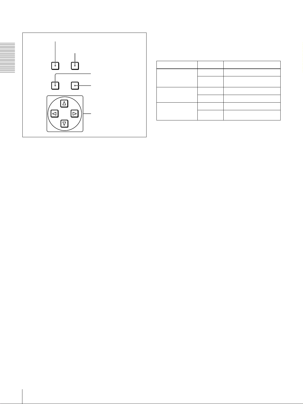
E Menu control section
a MENU button
b RESET (NO) button
MENU RESET(NO)
Chapter 1 Overview
TC
PRESET
SET(YES)
a MENU button
Press this button to display the menu on the monitor screen
and the time counter display. Press it again to exit the menu
display.
c TC PRESET button
d SET (YES) button
e fFgG buttons
e fFgG (arrow) buttons
Use these buttons to move around the menu items, and also
to modify the initial time code value and user bit data.
When the SEARCH ENABLE menu item (see page 60) is
set to ENABLE, you can also use these buttons to carry out
the following playback operations.
Playback type Direction Operation to carry out
Playback in range
±10 times normal
speed
Frame-by-frame
playback
Continuous
playback in jog
mode
Forward Press the G button.
Reverse Press the g button.
Forward Press the f button.
Reverse Press the F button.
Forward Hold down the f button.
Reverse Hold down the F button.
For details on modifying the time code value, see “To set
the initial time code value and user bit data” on page 46.
On how to use the menu, see Chapter 4 “Menu Settings.”
b RESET (NO) button
Press this button to:
• reset menu settings,
• reset the time data shown in the time counter display to
zero, or
• send a negative response to the prompts issued by the
unit.
c TC (time code) PRESET button
Use this button to set the initial value of the time code
produced by the internal time code generator and user bit
data.
For details on setting an initial time code value and user
bit data, see “To set the initial time code value and user bit
data” on page 46.
d SET (YES) button
Press this button to:
• save new settings, such as selected menu items and time
code settings, to memory, or
• send a positive response to the prompts issued by the
unit.
Location and Function of Parts
18
Page 19
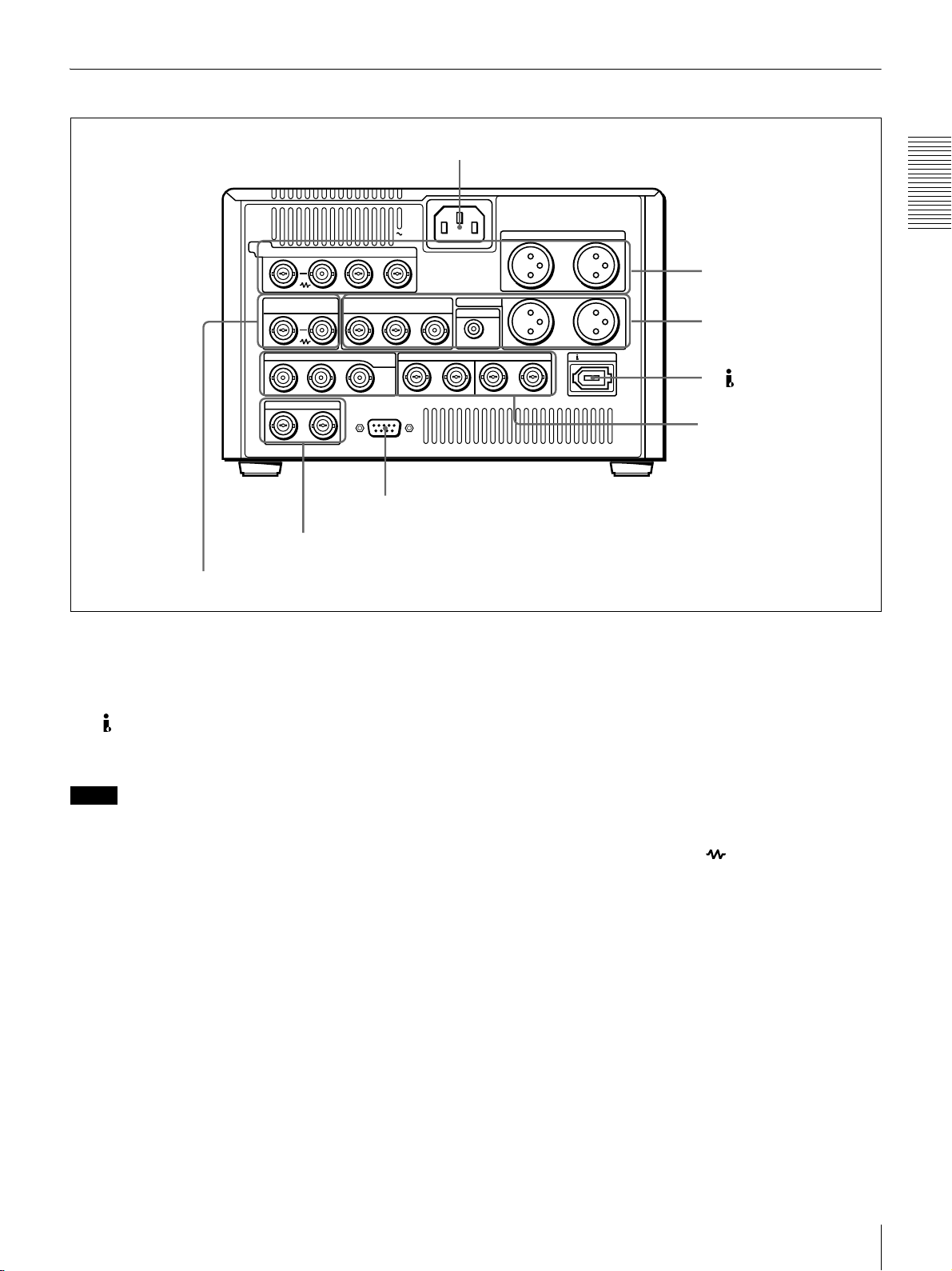
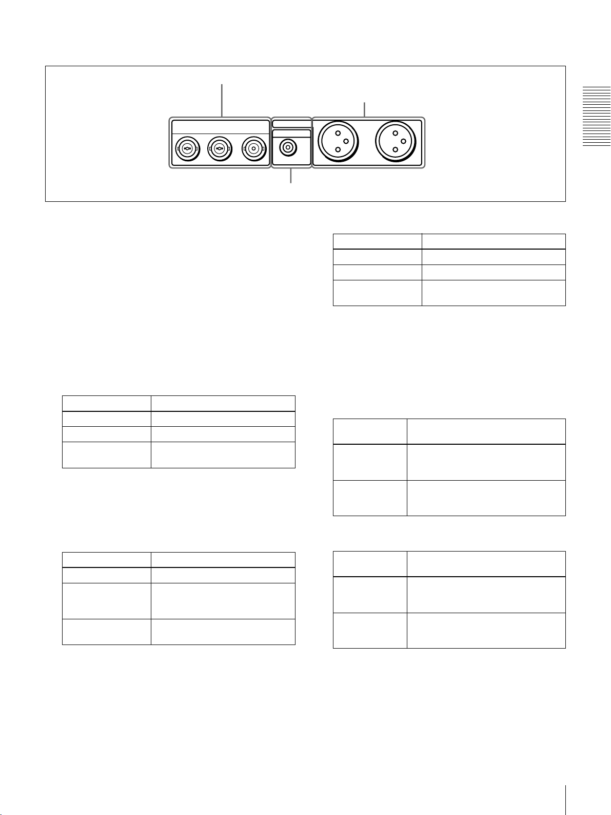
Rear Panel
a AC IN connector
VIDEO
Y/CPST R-Y/C B-Y
IN
REF.VIDEO VIDEO OUT
IN
IN OUT1 OUT2
INTC OUT
D Time code input/output section (see page 22)
d REF. VIDEO IN connectors
Y/CPST
AC IN
(SUPER)
B-Y/CPST
R-Y/C/CPST
SDI/SDTI
(QSDI)
REMOTE
IN
1/2 3/4 1/2 3/4
c REMOTE connector
a AC IN connector
Use the supplied power cord to connect this to an AC
outlet.
b DV IN/OUT connector (6-pin IEEE-1394)
This connector inputs and outputs digital video and audio
signals in DV format.
Notes
• If the unit is connected to a device equipped with a 6-pin
DV jack, when you intend to disconnect or reconnect the
DV cable, turn off the device and pull out the plug of its
power cord from the AC outlet beforehand. If you
connect or disconnect the DV cable while the device is
connected to the AC outlet, high-voltage current (8 to 40
V) is output from the DV jack of the device to this unit,
which may cause a malfunction.
• When connecting a device that has a 6-pin DV jack to
this unit, first connect the plug of the cable to the 6-pin
DV jack of the device.
• When searching at speeds in the range +
1
−
/30 to −1/2 times normal speed, the audio signal output
1
/2 to +1/30 or
from this connector and monitored on external
equipment may sound differently from the audio signal
played back on this unit.
AUDIO IN
AUDIO OUT
MONITOR
1/3
1/3
OUTAUDIO I/O (AES/EBU)
2/4
2/4
DV IN/OUT
A Analog video/audio signal
input section
(see page 20)
B Analog video/audio signal
output section
(see page 21)
b DV IN/OUT connector
C Digital signal input/output
section (see page 22)
c REMOTE connector (D-sub 9-pin)
Use the optional 9-pin remote cable to connect an editing
controller that supports this unit, or a VCR that supports
editing with two units (DSR-2000A/2000AP, etc.), to
connect those devices to this unit for remote control.
d REF. (reference) VIDEO IN connectors (BNC
type)
Input a reference video signal. The two connectors are
loop-through connectors. You can connect the reference
video signal input to the left connector to other equipment
via the right connector (marked ). When no connection
is made to the right connector, the left connector is
terminated with an impedance of 75 Ω automatically.
Chapter 1 Overview
Location and Function of Parts
19
Page 20
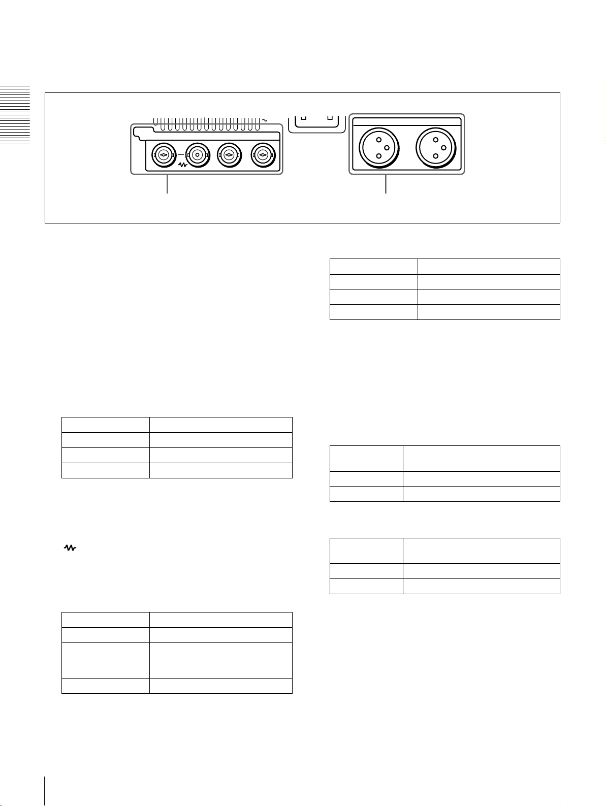
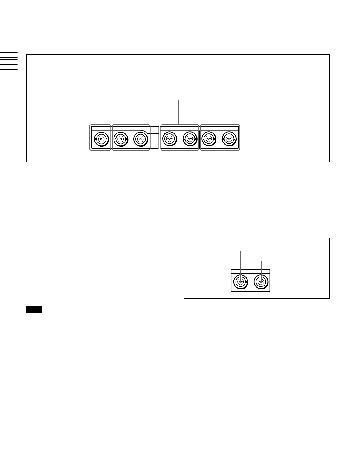
A Analog video/audio signal input section (optional DSBK-1505 Analog Input Board)
The connectors in this section are available when the
optional DSBK-1505 board is installed.
VIDEO
Y/CPST R-Y/C B-Y
IN
Chapter 1 Overview
a VIDEO IN connectors b AUDIO IN 1/3 and AUDIO IN 2/4 connectors
a VIDEO IN connectors (BNC type)
There are the following VIDEO IN connectors for
inputting analog video signals:
• Y/CPST (loop-through connectors)
•R
−Y/C
•B
−Y
The signals you can connect to these connectors depend on
the selection made with the VIDEO button in the video/
audio input selection section. The selection is indicated by
the VIDEO indicators in the INPUT signal display section.
The analog video signals that can be input to these
connectors are as follows.
When COMPOSITE is selected:
Connectors Input signals
Y/CPST Composite signal
R−Y/C — (not usable)
B−Y — (not usable)
The two Y/CPST connectors are loop-through
connectors. When using the signal input to the left Y/
CPST connector as a reference video signal, for
example, you can bridge-connect the signal to other
equipment via the right Y/CPST connector (marked
). When no connection is made to the right Y/
CPST connector, the left Y/CPST connector is
terminated with an impedance of 75 Ω automatically.
When S VIDEO is selected:
Connectors Input signals
Y/CPST Y signal
R−Y/C C signal
(3.58 MHz for DSR-1500A/
4.43 MHz for DSR-1500AP)
B−Y — (not usable)
AC IN
AUDIO IN
1/3
When Y
–R,B is selected:
Connectors Input signals
Y/CPST Y signal
R−Y/C R−Y signal
B−YB−Y signal
2/4
b AUDIO IN 1/3 and AUDIO IN 2/4 connectors
(XLR-3 pin, female)
Use these connectors to input analog audio signals from an
external video cassette player or other audio equipment.
The signals input to these connectors are recorded on the
audio channels determined by the current audio recording
mode, as follows.
When in 2 CH (48 kHz) mode:
Input
connectors
AUDIO IN 1/3 Audio channel 1
AUDIO IN 2/4 Audio channel 2
Audio channels on which input
signals are recorded
When in 4 CH (32 kHz) mode:
Input
connectors
AUDIO IN 1/3 Audio channels 1 and 3
AUDIO IN 2/4 Audio channels 2 and 4
Audio channels on which input
signals are recorded
You can switch the audio recording mode with the REC
MODE menu item (see page 66). The selection is indicated
by the REC MODE display on the front panel.
Location and Function of Parts
20
Page 21
B Analog video/audio signal output section
a VIDEO OUT connectors
b AUDIO OUT 1/3 and AUDIO OUT 2/4 connectors
VIDEO OUT
Y/CPST R-Y/C/CPST
(SUPER)
B-Y/CPST
AUDIO OUT
MONITOR
c MONITOR connector
a VIDEO OUT connectors (BNC type)
There are the following VIDEO OUT connectors for
outputting analog video signals:
•Y/CPST
•R
−Y/C/CPST
•B
−Y/CPST (SUPER)
The signals output from these connectors depend on the
setting of the VIDEO OUTPUT menu item (see page 68).
The setting is indicated by the VIDEO indicators in the
OUTPUT signal display section on the front panel.
The analog video signals that can be output from these
connectors are as follows.
When COMPOSITE is selected:
Connectors Output signals
Y/CPST Composite signal
R−Y/C/CPST Composite signal
B−Y/CPST
(SUPER)
Composite signal
When the CHARA. DISPLAY menu item (see page
61) is set to ON (factory default setting), the
B−Y/
CPST (SUPER) connector outputs a composite video
signal with superimposed text information.
1/3
When Y
Connectors Output signals
Y/CPST Y signal
R−Y/C/CPST R−Y signal
B−Y/CPST
(SUPER)
2/4
–R, B is selected:
B−Y signal
b AUDIO OUT 1/3 and AUDIO OUT 2/4 connectors
(XLR-3 pin, male)
These connectors output analog audio signals. The output
audio channels are determined by the playback audio mode
and the setting (1/2 CH or 3/4 CH) of the AUDIO
OUTPUT menu item (see page 68) as follows.
When in 2 CH (48 kHz or 44.1 kHz) mode:
Output
connectors
AUDIO OUT 1/3 Audio channel 1 (when 1/2 CH is
AUDIO OUT 2/4 Audio channel 2 (when 1/2 CH is
Output audio channels
selected) or silent (when 3/4 CH is
selected)
selected) or silent (when 3/4 CH is
selected)
Chapter 1 Overview
When S-VIDEO is selected:
Connectors Output signals
Y/CPST Y signal
R−Y/C/CPST C signal
(3.58 MHz for DSR-1500A/
4.43 MHz for DSR-1500AP)
B−Y/CPST
(SUPER)
Composite signal
When the CHARA. DISPLAY menu item (see page
61) is set to ON (factory default setting), the B
CPST (SUPER) connector outputs a composite video
signal with superimposed text information.
−Y/
When in 4 CH (32 kHz) mode:
Output
connectors
AUDIO OUT 1/3 Audio channel 1 (when 1/2 CH is
AUDIO OUT 2/4 Audio channel 2 (when 1/2 CH is
Output audio channels
selected) or audio channel 3 (when 3/
4 CH is selected)
selected) or audio channel 4 (when 3/
4 CH is selected)
The current playback audio mode is indicated by the PB Fs
display on the front panel.
c MONITOR connector (RCA phono jack)
This connector outputs audio signals for monitoring. The
audio signals to be output from this connector can be
selected with the MONITOR SELECT button and
METER CH-1/2 3/4 button on the front panel.
Location and Function of Parts
21
Page 22
C Digital signal input/output section (optional DSBK-1501 Digital Input/Output Board)
The connectors in this section are available when the
optional DSBK-1501 board is installed.
a SDI/SDTI (QSDI) IN connector
Chapter 1 Overview
IN OUT1 OUT2 IN
b SDI/SDTI (QSDI) OUT1/OUT2 connectors
a SDI/SDTI (QSDI) IN (Serial Digital Interface/
Serial Data Transport Interface (QSDI) input)
connector (BNC type)
This connector inputs digital video and audio signals in
SDTI (QSDI) or SDI format. To select the required input
signal formats, use the SDTI/i.LINK button or VIDEO
button on the front panel. The current input signal
selections are indicated in the INPUT signal display
section on the front panel.
b SDI/SDTI (QSDI) OUT1/OUT2 (Serial Digital
Interface/Serial Data Transport Interface (QSDI)
output 1/output 2) connectors (BNC type)
These connectors output digital video and audio signals in
SDTI (QSDI) or SDI format. To select these output signal
formats, use the DIGITAL OUTPUT menu item (see page
68). The current output signal selections are indicated in
the OUTPUT signal display section on the front panel.
c AUDIO (AES/EBU) IN 1/2 and AUDIO (AES/EBU)
IN 3/4 connectors
SDI/SDTI
(QSDI)
1/2 3/4 1/2 3/4
d AUDIO (AES/EBU) OUT 1/2 and AUDIO (AES/
EBU) OUT 3/4 connectors (BNC type)
These connectors output digital audio signals in AES/EBU
format.
The left connector (1/2) is for audio channels 1 and 2, and
the right connector (3/4) is for audio channels 3 and 4.
D Time code input/output section
d AUDIO (AES/EBU) OUT 1/2 and AUDIO
(AES/EBU) OUT 3/4 connectors
OUTAUDIO I/O (AES/EBU)
a TC IN connector
b TC OUT connector
INTC OUT
Note
When searching at speeds in the range +1/2 to +1/30 or
1
−
/2 to −1/30 times normal speed, the audio signal output
from these connectors in SDTI (QSDI) format and
monitored on external equipment may sound differently
from the audio signal played back on this unit.
c AUDIO (AES/EBU) IN 1/2 and AUDIO (AES/
EBU) IN 3/4 connectors (BNC type)
Input digital audio signals in AES/EBU format to these
connectors.
The left connector (1/2) is for audio channels 1 and 2, and
the right connector (3/4) is for audio channels 3 and 4.
Location and Function of Parts
22
a TC IN (time code input) connector (BNC type)
Input externally generated SMPTE time code (for DSR1500A) or EBU time code (for DSR-1500AP) to this
connector.
b TC OUT (time code output) connector (BNC type)
This connector outputs a time code according to the
operating state of the unit, as follows:
During playback: the playback time code
During recording: the time code generated by the internal
time code generator or the time code input to the TC
IN connector. When the EE OUT PHASE menu item
(see page 64) is set to MUTE, no time code is output.
Page 23
Recording and Playback
Usable Cassettes
This unit can use the DVCAM cassettes listed below.
Model name Size
PDV-64*/94*/124*/184* Standard size
PDVM-12*/22*/32*/40* Mini size
The * in each model name is actually “ME” (indicating that a cassette memory
is contained), or “N” (indicating that no cassette memory is contained).
The numbers in each model name indicate the maximum recording/playback
time (in minutes) for each model. For example, the PDV-184ME has a
maximum recording/playback time of 184 minutes.
Cassettes usable for playback only
Large- and medium-size DVCPRO (25 Mbps) cassettes are usable for playback
only.
Chapter 2
Notes
• If you insert an incorrect type of cassette, it will be automatically ejected.
• Although this unit can use DV series consumer cassettes, video or audio noise
may occur on some tapes.
For reliable playback, editing, recording, and storage, use DVCAM cassettes.
• Cassettes that have been recorded by a DV-format recorder can be played
back on this unit but cannot be used for recording at editing operation. When
you insert such a cassette into this unit, the NO EDIT indicator lights up in the
display section on the front panel of this unit.
Usable Cassettes
23
Page 24
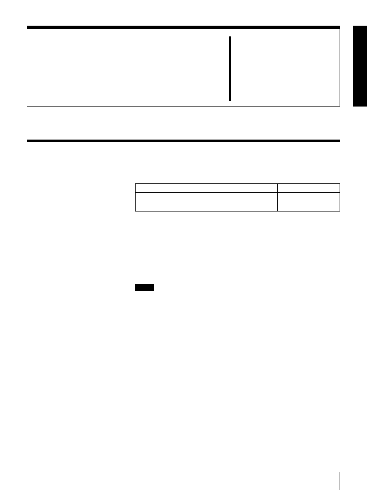
DVCAM cassettes
Chapter 2 Recording and Playback
Notes on using cassettes
The following figure illustrates the DVCAM cassettes.
REC/SAVE switch
For details of this switch, see “Preventing accidental
erasure” on page 25.
Mini size Standard size
Cassette memory
This memory is used to store ClipLink log data.
• Before storing the cassette for a long period of time, rewind the tape to the
beginning and be sure to put the cassette in its storage case, preferably on end
instead of flat on its side.
Storing a cassette in any other condition (not rewound, out of its case, etc.)
may cause the video and audio contents to become damaged over time.
• If the cassette memory connector (contact point) becomes dirty, connection
problems may occur, causing a loss of functions. Remove away any dust or
dirt from this area before using the cassette.
• If the cassette is dropped on the floor or otherwise receives a hard impact, the
tape may become slackened and may not record and/or play back correctly.
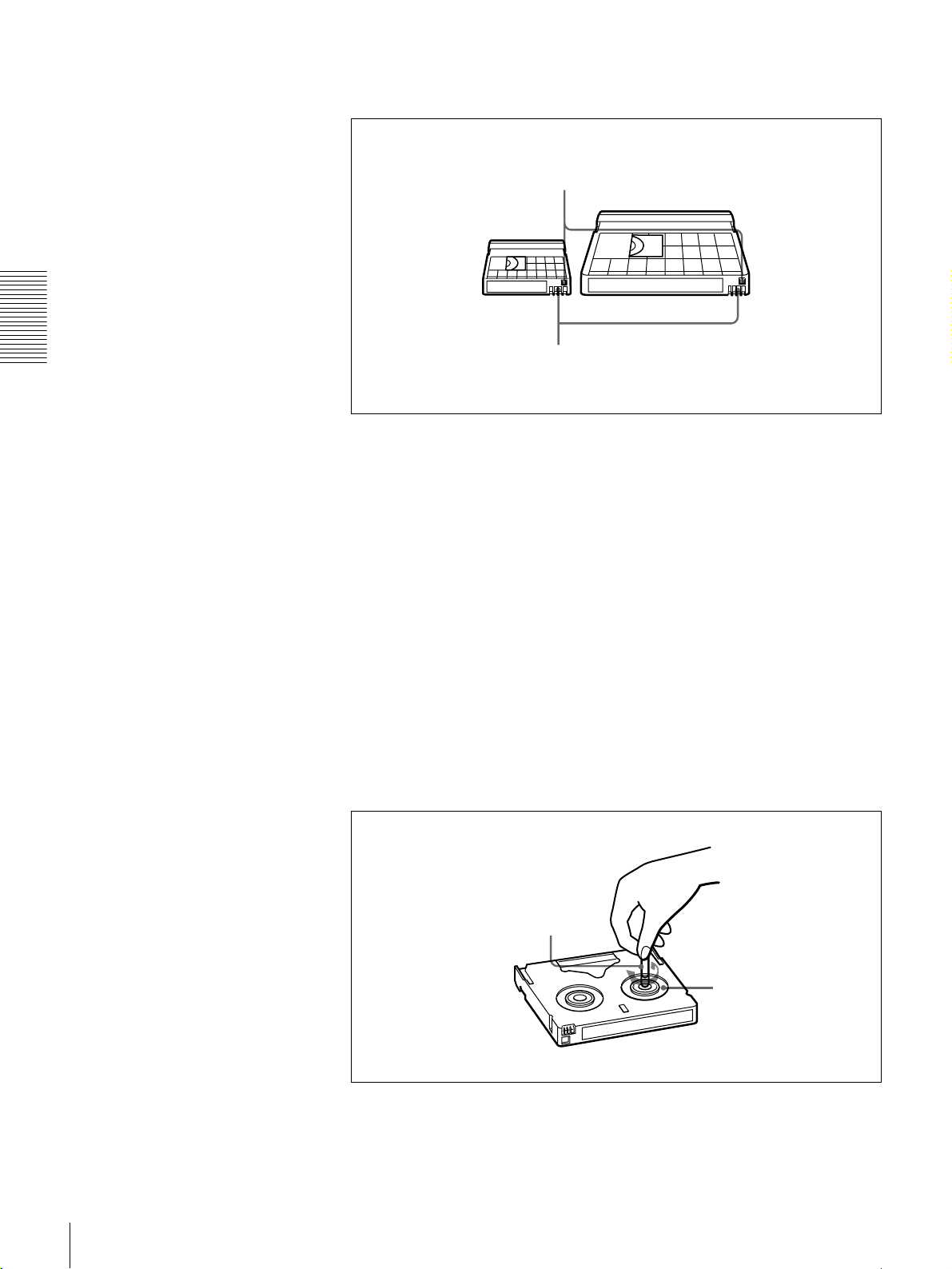
Checking the tape for slack
For information about how to check the tape for slack, see the next section.
Using a paper clip or a similar object, turn the reel gently in the direction shown
by the arrow. If the reel does not move, there is no slack. Insert the cassette into
the cassette compartment, and after about 10 seconds take it out.
Paper clip, etc.
Reel
24
Usable Cassettes
Page 25

Preventing accidental erasure
Set the REC/SAVE switch on the cassette to SAVE to prevent accidental
erasure of recorded contents.
To enable re-recording
Set the REC/SAVE switch to REC.
When this switch is set to SAVE, the unit cannot record on the tape.
Inserting and Ejecting Cassettes
Inserting a cassette
This unit accepts three sizes of cassette: L (standard size), M (medium size:
DVCPRO) and S (mini size). When inserting a cassette in the unit, make sure
its tape window faces upward as shown in the following figure.
REC/SAVE switch
Set to SAVE
REC
SAVE
Chapter 2 Recording and Playback
Outer guides
Inner guides
Mini size (Insert the cassette into the
middle of the cassette compartment.)
Standard size
Tape window facing upward
Medium size (Align the cassette with
the outer guides, then slide it in over
the inner guides.)
Tape window facing upward
Usable Cassettes
25
Page 26
No double insertion of cassettes
Ejecting a cassette
Chapter 2 Recording and Playback
When you insert a cassette, the orange lock-out plate appears in the cassette
compartment to prevent double insertion.
Press the EJECT button.
EJECT button
OVER
OVER
dB
dB
INPUT
0
0
AUDIO
VIDEO
V:SDTI
COMPOSITE
CH-1 1/2
CH-2 3/4
SDTI
ANALOG
ANALOG
S VIDEO
-12
-12
i.LINK
AES/EBU
AES/EBU
Y-R,B
-20
-20
SDI SG
SDI SG SDI SG
OUTPUT
-30
-30
AUDIO
VIDEO
-40
-40
SDI
COMPOSITE
CH 1/2
-60
-60
SDTI
S VIDEO
CH 3/4
CH-
CH-
2 4
1 3
Y-R,B
REW PLAY F FWD STOP REC
REC INHI
SERVO
U-BIT
TC NOCLEDIT
HOURS MINUTES SECONDS FRAMES
PB F
S
REC MODE
VITC
48K 44.1K 32K
2CH 4CH
EDIT MODE
REPEATCOUNTER
REMOTE
9P i.LINK
26
Usable Cassettes
Page 27

Recording
This section describes the necessary settings and operations to perform
recording on this unit. The same settings and operations apply whether you are
using the unit as part of an editing system, for dubbing, or as a stand-alone
recorder.
For the necessary connections for recording and the settings not covered in this
section, see Chapter 5 “Connections and Settings.”
For dubbing of SDTI (QSDI) format signals, use the AUTO FUNCTION menu
item SDTI DUBBING (see page 72). For details, see “Digitally Dubbing
Signals in DVCAM/DV Format” on page 52.
Chapter 2 Recording and Playback
For this unit, recording in DVCAM format is recommended, but recording in
DV (SP mode only) format is also possible.
Notes
• When carrying out multiscene continuous recording on a DV (SP) tape using
this unit with an optional remote control unit such as the DSRM-10, on rare
occasions, the video may be disrupted at the IN point of the first scene or the
audio may be muted due to a REC MODE (audio recording mode) difference
between the tape and this unit.
There may also be cases in which the unit is subjected to some functional
restrictions attributable to the use of the DV format.
• When using the unit as an editor, the optional boards corresponding to the
input signal formats to be used are required.
For details about the optional boards, see “Optional Accessories” (page 8).
Recording
27
Page 28
Settings for Recording
Player (DSR-1600/1600P, etc.)
OVER
OVER
OVER
OVER
dB
dB
dB
dB
dB
dB
dB
dB
0
0
0
0
0
0
0
0
-12
1
-12
1
-12
1
-12
1
-20
0
-20
0
-20
0
-20
0
-1
-1
-1
-1
-30
-30
-30
-30
-40
-40
-40
-40
-2
-2
-2
-2
PB FS
-60
48k44.1k32k
-60
-60
-60
1
2
3
4
1
2
Video monitor
INPUT signal display
section
Chapter 2 Recording and Playback
LOCAL/REMOTE
switch
Recorder (DSR-1500A/1500AP)
3
OVER
OVER
dB
dB
7
INPUT
0
0
AUDIO
VIDEO
V:SDTI
COMPOSITE
CH-1 1/2
CH-2 3/4
SDTI
ANALOG
ANALOG
S VIDEO
-12
-12
i.LINK
AES/EBU
AES/EBU
Y-R,B
-20
-20
SDI SG
SDI SG SDI SG
OUTPUT
-30
-30
AUDIO
VIDEO
-40
-40
SDI
COMPOSITE
CH 1/2
-60
-60
SDTI
S VIDEO
CH 3/4
CH-
CH-
2 4
1 3
Y-R,B
REW PLAY F FWD STOP REC
REC INHI
SERVO
U-BIT
TC NOCLEDIT
HOURS MINUTES SECONDS FRAMES
PB FS
REC MODE
VITC
48K 44.1K 32K
2CH 4CH
EDIT MODE
REPEATCOUNTER
REMOTE
9P i.LINK
6
4
5
Audio level meters
When controlling this unit from an editing control unit connected to the
REMOTE connector, see “LOCAL/REMOTE switch” on page 10 and the
description of the REMOTE I/F menu item on page 68.
1 Power on the video monitor, then set its input switches according to the
signals input from this unit.
2 Set up the player to play back a tape.
For details, refer to the operating instructions for the player.
3 Power on this unit by pressing on the side of the POWER switch.
4 When the REMOTE indicator is off (the external editing control unit is not
used), use the COUNTER SELECT button to select the type of time data to
be used.
Each press of this button cycles through three options: COUNTER (CNT
value), TC (time code), and U-BIT (user bit data). The time data type
indicator for each option lights as it is selected.
Selected time data Time data type indicator
Count value of the time counter COUNTER
Time code TC
User bit data U-BIT
28
Recording
Page 29
When the REMOTE indicator is lit, selection of the time data type is carried
out at the editing control unit.
5 Select the formats of video and audio input signal to be recorded.
Use the INPUT SELECT buttons in the video/audio input setting section to
select the desired signal formats. Each selection is shown by a lit indicator
in the INPUT signal display section.
Video input signal
(input connector)
Composite signal
(VIDEO IN: Y/CPST)
Separated Y/C signal
(VIDEO IN: Y/CPST and
R−Y/C)
Component signal
(VIDEO IN: Y/CPST,
R−Y/C, and B−Y)
SDI signal
(SDI/SDTI (QSDI) IN)
SDTI (QSDI) signal
(SDI/SDTI (QSDI) IN)
i.LINK-compatible digital
video signal in DV format
(i.DV IN/OUT)
Internal test video signal VIDEO SG in VIDEO group
a) The indicators without the corresponding optional boards (DSBK-1501/1505) installed in the
unit do not light.
Audio input signal
(input connector)
Analog signal
(AUDIO IN 1/3 and
AUDIO IN 2/4)
AES/EBU signal
(AUDIO (AES/EBU) IN)
SDI signal
(SDI/SDTI (QSDI) IN)
SDTI (QSDI) signal
(SDI/SDTI (QSDI) IN)
i.LINK-compatible digital
audio signal in DV format
(i.DV IN/OUT)
Internal test audio signal CH1 1/2 and CH2 3/4 SG in AUDIO group
a) The indicators without the corresponding optional boards (DSBK-1501/1505) installed in the
unit do not light.
Corresponding INPUT
SELECT button
VIDEO COMPOSITE in VIDEO
VIDEO S VIDEO in VIDEO
VIDEO Y−R,B in VIDEO group
VIDEO SDI in VIDEO group
SDTI/i.LINK SDTI: both SDTI video
SDTI/i.LINK i.LINK
Corresponding INPUT
SELECT button
CH1 1/2 and CH2 3/4 ANALOG in AUDIO
CH1 1/2 and CH2 3/4 AES/EBU in AUDIO
CH1 1/2 and CH2 3/4 SDI in AUDIO group
SDTI/i.LINK SDTI
SDTI/i.LINK i.LINK
Lit indicator in the
INPUT signal display
section
group
group
V:SDTI: only SDTI video
Lit indicator in the
INPUT signal display
section
group
group
a)
and audio input
signals are
recorded.
input signal is
recorded.
a)
Chapter 2 Recording and Playback
Caution
Once you have started recording, you cannot change the input signal
selection.
Recording
29
Page 30

6 Select the audio mode.
Select either two-channel mode (2 CHANNEL) or four-channel mode (4
CHANNEL) with the REC MODE menu item (see page 66). The
corresponding indicator lights in the REC MODE display.
Audio mode Lit indicator in the REC MODE display
2-channel mode 2CH
4-channel mode 4CH
Cautions
• When recording in DVCAM format or this unit’s DV (SP) format, two
audio recording modes, with either two channels at 48 kHz or four
channels at 32 kHz, can be used. It is not possible to select any other mode
(for example with four channels at 48 kHz).
Chapter 2 Recording and Playback
• During audio editing, if a signal used in assemble or insert editing is in a
different mode from the base tape, the signals will be discontinuous at the
edit points, and correct editing will not be obtained. For this reason, the
menu settings on this unit are arranged to inhibit audio editing between
different modes.
For smooth editing operations, check the audio recording mode of the
base tape beforehand.
• Once you have started recording, you cannot change the audio mode or
recording format.
• If on a tape there is a point where the audio mode is switched, it is not
possible to carry out insert editing over a section including that point.
• When, in 4-channel mode, analog audio is selected for all four channels
(channels 1/2 and 3/4), the same analog audio signals are recorded on
channels 1 and 3 and on channels 2 and 4, respectively.
Recording Procedure
7 When manually adjusting audio input levels
With the VAR switch on the front panel set to REC, use the REC/PB
LEVEL control knob for each channel to adjust the audio input level.
Watching the audio level meter in E-E mode, adjust the level so that the
meter does not indicate higher values than 0 dB when the audio signal is at
its maximum. When the level exceeds 0 dB, the OVER indicator lights.
When recording at reference level
When the VAR switch on the front panel is set to PRESET, recording is
carried out at the preset reference level.
Reference level setting
The factory-preset reference level for analog audio input is −20 dB (DSR1500A) or −18 dB (DSR-1500AP). This setting can be changed using the
LEVEL SELECT menu item (see page 67).
For recording in DV (SP) format, the reference level is fixed at −12 dB.
This section describes the procedure to perform recording on this unit, showing
an example session in which playback signals coming from a player VCR will
be recorded on the tape loaded in the unit.
30
Recording
Page 31

OVER
OVER
dB
dB
INPUT
0
0
V:SDTI
SDTI
-12
-12
i.LINK
-20
-20
OUTPUT
-30
-30
-40
-40
SDI
-60
-60
SDTI
CH-
CH-
2 4
1 3
REW PLAY F FWD STOP REC
Recorder
(DSR-1500A/1500AP)
OVER
OVER
OVER
OVER
dB
dB
dB
dB
dB
dB
dB
dB
0
0
0
0
0
0
0
0
1
1
1
1
-12
-12
-12
-12
0
0
0
0
-20
-20
-20
-20
-1
-1
-1
-1
-30
-30
-30
-30
-40
-40
-40
-40
-2
-2
-2
-2
PB FS
-60
1
48k44.1k32k
-60
-60
-60
2
3
4
AUDIO
VIDEO
COMPOSITE
CH-1 1/2
ANALOG
S VIDEO
AES/EBU
Y-R,B
SDI SG
SDI SG SDI SG
AUDIO
VIDEO
COMPOSITE
CH 1/2
S VIDEO
CH 3/4
Y-R,B
1
SERVO
U-BIT
CH-2 3/4
TC NOCLEDIT
ANALOG
AES/EBU
HOURS MINUTES SECONDS FRAMES
PB FS
REC MODE
2CH 4CH
48K 44.1K 32K
LOCAL/REMOTE
REC INHI
REPEATCOUNTER
VITC
REMOTE
9P i.LINK
EDIT MODE
switch
2
Chapter 2 Recording and Playback
Player
(DSR-1600/1600P, etc.)
3
Notes
• When controlling this unit from an editing control unit connected to the
REMOTE connector of this unit, set the LOCAL/REMOTE switch to
REMOTE, turning the REMOTE indicator on. When not, set the switch to
LOCAL, turning the indicator off.
• If you intend to use a tape recorded on this unit in a system comprising a DSR85/85P and an ES-7 EditStation, it is recommended to record color bars on at
least the first 40 seconds of the tape.
When transferring digital signals from the DSR-85/85P to the ES-7
EditStation at four times normal speed, there must be recording for
approximately 40 seconds before the IN point.
1 After checking the following items, hold the cassette with the tape window
facing upward, then insert it into the recorder (this unit) as illustrated on
page 25.
.
Item to check See section
Make sure that the REC/SAVE switch
of the cassette is set to REC.
Check for tape slack. “Checking the tape for slack” on page
Make sure that the “HUMID!” alarm is
not shown in the time counter display.
“Preventing accidental erasure” on
page 25
24
“Condensation” on page 95
The cassette is automatically drawn into the unit and the tape is wound
round the head drum. The tape is stationary while the head drum rotates, and
the STOP button lights.
Recording
31
Page 32

If the REC INHI indicator lights:
It indicates that the REC/SAVE switch of the loaded cassette has been set
to SAVE. Press the EJECT button in the tape transport control section to
remove the cassette, then set the REC/SAVE switch to REC and reload the
cassette.
Note
When ejecting and loading cassettes, make sure that the unit has been
powered on.
2 Hold down the REC button and press the PLAY button.
This puts the unit into recording mode, and the tape starts moving.
3 Press the PLAY button on the player.
Chapter 2 Recording and Playback
The player starts the playback operation, at which point this unit starts
recording the input playback signals.
Cautions
• Once you have started recording, you cannot change the audio mode or
recording format.
• If on a tape there is a point where the audio mode is switched, it is not
possible to carry out insert editing over a section including that point.
If the following indicators light when a cassette is loaded
Indicator It means:
Cassette memory indicator The loaded cassette contains a cassette memory.
CL indicator There is ClipLink log data stored in the cassette
NO EDIT indicator • The recording format of the tape is DV, or a
memory on the loaded cassette.
Caution
With such a cassette, carrying out recording destroys
the ClipLink log data.
DVCPRO tape is inserted.
Replace the tape with one that has been recorded
in DVCAM format.
• The recording format selected on this unit is DV
(SP). In this case, you cannot use the editing
functions.
32
During editing operation
The audio recording mode selected on this unit does
not coincide with that of the tape.
In this case, set the unit for the same audio recording
mode as with the tape.
However, If your current purpose is recording only,
you can use the tape as it is.
For more details, see “Troubleshooting” on page 98.
Recording
Page 33

To perform the following operations
Operation Do this:
Stop recording. Press the STOP button.
The unit enters stop mode, and will automatically
switch to standby off mode after the time period set
with the STOP TIMER menu item (see page 64) for
tape protection.
Remove the cassette. Press the EJECT button.
After a few seconds, the tape is unwound from the
head drum and the cassette is automatically ejected.
If a CNT value is shown on the time counter display
(the time data type indicator “COUNTER” is lit), the
CNT value is reset.
Inhibit the unit from
outputting text information
Set the CHARA. DISPLAY menu item (see page 61)
to OFF.
(time data, operation mode
indications, etc.) to the
video monitor.
Change the time period
before the unit switches
Change the setting of the STOP TIMER menu item
(see page 64).
from stop mode to standby
off mode.
Reference level for recording in DV (SP) format
On many consumer DV devices, recording is carried out at a reference level of
−12 dB. Threfore, when recording in DV (SP) format on this unit, using the
fixed referenced level of −12 dB is recommended. When dubbing DVCAM
source material recorded at a different reference level, you can carry out manual
adjustment as described in the following.
Chapter 2 Recording and Playback
Player (DSR-1800A/1800AP/1600Aa)/
a)
1600AP
a) On the DSR-1600A/1600AP, tape recorded
b) DSR-1500A/1500AP only
/1500A/1500AP) in E-E mode
Audio input selection: INT SG/1
kHz
REC mode: 2ch or 4ch depending
on DVCAM source
Reference level: Reference level
of the DVCAM source
VAR switch
at the reference level is played back.
b)
: PRESET
i.LINK/
SDTI (QSDI)/
SDI
Recorder (DSR-1500A/
1500AP) in E-E mode
REC FORMAT: DV (SP)
VAR switch: REC
For each channel, observing
the audio level meter, adjust
the audio level to −12 dB
with the level control knob.
Recording
33
Page 34

Playback
Settings for Playback
This section describes the settings and operations necessary to perform playback
on this unit. The same settings and operations apply whether you are using the
unit as part of an editing system, for dubbing, or as a stand-alone player VCR.
For the necessary connections for playback and the settings not covered in this
section, see Chapter 5 “Connections and Settings” (page 79).
Chapter 2 Recording and Playback
Video monitor
2
Player (DSR-1500A/1500AP)
1
OVER
OVER
dB
dB
INPUT
0
0
AUDIO
VIDEO
V:SDTI
COMPOSITE
CH-1 1/2
CH-2 3/4
SDTI
ANALOG
ANALOG
S VIDEO
-12
-12
i.LINK
AES/EBU
AES/EBU
Y-R,B
-20
-20
SDI SG
SDI SG SDI SG
OUTPUT
-30
-30
AUDIO
VIDEO
-40
-40
SDI
COMPOSITE
CH 1/2
-60
-60
SDTI
S VIDEO
CH 3/4
CH-
CH-
2 4
1 3
Y-R,B
REW PLAY F FWD STOP REC
1 Power on this unit by pressing on the side of the POWER switch.
2 Power on the video monitor and set its switches as shown below.
Switch Setting
75 Ω termination switch ON (or attach a 75 Ω terminator.)
Input switch Set according to the type of input signal from this
unit.
REC INHI
SERVO
U-BIT
TC NOCLEDIT
HOURS MINUTES SECONDS FRAMES
PB F
S
REC MODE
VITC
2CH 4CH
EDIT MODE
48K 44.1K 32K
REPEATCOUNTER
REMOTE
9P i.LINK
34
Playback
Page 35

Playback Procedure
1
OVER
OVER
dB
dB
INPUT
U-BIT
VIDEO
COMPOSITE
SDTI
S VIDEO
i.LINK
Y-R,B
SDI SG
VIDEO
SDI
COMPOSITE
SDTI
S VIDEO
Y-R,B
SERVO
AUDIO
CH-1 1/2
CH-2 3/4
TC NOCLEDIT
ANALOG
ANALOG
AES/EBU
AES/EBU
SDI SG SDI SG
AUDIO
HOURS MINUTES SECONDS FRAMES
CH 1/2
CH 3/4
PB FS
48K 44.1K 32K
REC MODE
2CH 4CH
0
0
V:SDTI
-12
-12
-20
-20
OUTPUT
-30
-30
-40
-40
-60
-60
CH-
CH-
2 4
1 3
REW PLAY F FWD STOP REC
LOCAL/
REC INHI
REPEATCOUNTER
VITC
REMOTE
9P i.LINK
EDIT MODE
REMOTE switch
2
Note
When controlling this unit from an editing control unit connected to the
REMOTE connector of this unit, set the LOCAL/REMOTE switch of this unit
to REMOTE, turning the REMOTE indicator on. When not, set the switch to
LOCAL, turning the indicator off.
1 Insert a cassette.
For details of cassette insertion see page 25, and for usable cassette types
see page 23.
The cassette is automatically drawn into the unit and the STOP button
lights. A few seconds later, if the STOP menu item under the AUTO EE
SELECT menu item (see page 60) is set to PB, a still image will appear on
the monitor screen.
2 Press the PLAY button.
This starts the playback operation. When the tape is played back all the way
to the end, the unit automatically rewinds it and then stops.
If the following indicators light when a cassette is loaded
Indicator It means:
Cassette memory indicator The loaded cassette contains a cassette memory.
CL indicator There is ClipLink log data stored in the cassette
NO EDIT indicator • The tape was recorded in the DV format, or a
memory on the loaded cassette.
DVCPRO tape is inserted.
You cannot use it as a recording tape for editing.
• The recording format selected on this unit is DV
(SP).
Chapter 2 Recording and Playback
Playback
35
Page 36

To perform the following operations
Operation Do this:
Stop playback. Press the STOP button.
The unit enters stop mode, and will automatically
switch to standby off mode after the time set with the
STOP TIMER menu item (see page 64) for tape
protection.
Adjust the audio playback
level.
Chapter 2 Recording and Playback
Play back in shuttle mode
while monitoring the
a)
video.
Play back in jog mode while
monitoring the video.
a)
For digital (optional DSBK-1501 required) or
analog audio output
Set the VAR switch on the front panel to PB and use
the REC/PB LEVEL control knob for each channel.
For outputs from the PHONES connector and
MONITOR connector
Use the PHONES control knob on the front panel
(outputs from the PHONES connector on the front
panel and the MONITOR connector on the rear panel
are adjusted).
To carry out a high-speed search (10 times normal
speed) in forward or reverse direction, press the G or
g button.
To return to normal-speed playback, press the PLAY
button.
Note
When performing these operations, set the LOCAL/
REMOTE switch on the front panel to LOCAL.
To carry out frame-by-frame playback in forward or
reverse direction, press the f or F button.
When you hold down the f or F button, playback is
continued in jog mode (−
1
/2 times normal speed) in
forward or reverse direction.
Note
When performing these operations, set the LOCAL/
REMOTE switch on the front panel to LOCAL.
Inhibit the unit from
outputting text information
Set the CHARA. DISPLAY menu item (see page 61)
to OFF.
(time data, operation mode
indications, etc.) to the
video monitor.
Remove the cassette. Press the EJECT button.
If a CNT value is shown in the time counter display,
the CNT value is reset.
Disable the automatic
rewind function.
Change the time period
before the unit switches
Set the AUTO REW menu item (see page 61) to
DISABLE.
Change the setting of the STOP TIMER menu item
(see page 64).
from stop mode to standby
off mode.
a) When the SEARCH ENABLE menu item (see page 60) is set to ENABLE.
36
Playback
Page 37

Repeat Playback—Automatic Cyclical Playback
Proceed as follows to perform automatic cyclical playback of recording (repeat
playback) between selected start and end points.
1 Set the desired repeat start and end points with the REPEAT FUNCTION
menu item (see page 59).
You can set points A and B as start and end points by following the
procedure described in the next section.
2 Set the REPEAT MODE menu item (see page 59) to ON.
The REPEAT indicator lights.
3 Press the SET (YES) button to save the new setting and close the menu.
4 Press the PLAY button.
The unit repeats playback between the repeat start and end points set in step
1.
Setting Points A and B for Repeat Playback
You can set the repeat playback start point (point A) and end point (point B) by
using the current tape position or inputting time code values.
To perform repeat playback after setting points A and B, press the PLAY button
when the REMOTE indicator is off. When the DSRM-10 Remote Control Unit
is connected to the CONTROL S connector on the front panel, you can also start
repeat playback by pressing its PLAY button with the REMOTE indicator of
this unit off.
Chapter 2 Recording and Playback
Note
When performing repeat playback using points A and B as the playback start
and end points, make sure that the REPEAT TOP and REPEAT END menu
items (see page 59) are set to A POINT and B POINT, respectively.
Playback
37
Page 38

Setting the current tape position as point A or B
Proceed as follows to set the current tape position as point A or B for repeat
playback.
MENU RESET(NO)
OVER
OVER
dB
dB
INPUT
SERVO
U-BIT
0
0
AUDIO
VIDEO
V:SDTI
COMPOSITE
CH-1 1/2
CH-2 3/4
TC NOCLEDIT
SDTI
ANALOG
ANALOG
S VIDEO
-12
-12
i.LINK
AES/EBU
AES/EBU
Y-R,B
-20
-20
SDI SG
SDI SG SDI SG
OUTPUT
-30
-30
AUDIO
VIDEO
-40
-40
-60
CH-
1 3
REW PLAY F FWD STOP REC
-60
CH-
2 4
SDI
COMPOSITE
SDTI
S VIDEO
Y-R,B
HOURS MINUTES SECONDS FRAMES
CH 1/2
CH 3/4
PB FS
REC MODE
2CH 4CH
48K 44.1K 32K
REC INHI
REPEATCOUNTER
VITC
REMOTE
9P i.LINK
EDIT MODE
TC
PRESET
SET(YES)
Buttons used for setting
the current tape position
Chapter 2 Recording and Playback
as point A
Buttons used for setting
the current tape position
as point B
While holding down the SET (YES) button in the menu control section, press
the g or G button. The time code value of the current tape position is set as point
A or B, and a message “A set” or “B set” is displayed for 0.5 second in the time
counter display.
Once set, the point A or B time code value is held in the non-volatile memory
of the unit until changed. It is not lost when the unit is powered off.
Note
When setting point A or B, you can only use a time code value. Even when
COUNTER is selected with the COUNTER SELECT button, you cannot use a
CNT value to set point A or B.
To check the point A or B time code value
Press the g or G button in the menu control section. While the button is held
down, the point A or B time code value is displayed on the monitor and in the
time counter display.
If you hold down the g and G buttons simultaneously, the value shown is the
point B time code value minus the point A time code value. If the point A time
code value is greater than the point B time code value, a minus sign (−) is shown
before the value.
38
Playback
Page 39

Inputting time code values for points A and B
Using the following procedure, you can modify the time code value for point A
or B.
1,15
8,11
1 Press the MENU button.
The following menu display appears.
MENU RESET(NO)
TC
PRESET
SET(YES)
5,7,9,12
13
12
2,3,4,6,10,11
Chapter 2 Recording and Playback
SYSTEM MENU
SETUP MENU
AUTO FUNCTION
HOURS METER
Monitor screen
Setup menu
Time counter display
2 With “SETUP MENU” selected, press the G button.
The display changes as follows.
OPERATIONAL FUNCTION
SETUP MENU
DISPLAY CONTROL
TIME CODE
SETUP BANK OPERATION
MENU GRADE :BASIC
Operational
Time counter display
Monitor screen
Playback
39
Page 40

3 With “OPERATIONAL FUNCTION” selected, press the G button.
The display changes as follows.
OPERATIONAL FUNCTION
SETUP MENU
REPEAT FUNCTION
AUTO EE SELECT
LOCAL ENABLE :STP&EJ
Monitor screen
Chapter 2 Recording and Playback
>REP FUNC
Time counter display
4 With “REPEAT FUNCTION” selected, press the G button.
The contents of the REPEAT FUNCTION menu item are displayed.
OPERATIONAL FUNCTION
SETUP MENU
REPEAT FUNCTION
REPEAT MODE
REPEAT TOP
REPEAT END
A PRESET
B PRESET
:OFF
:
T.TOP
:
V.END
>> REPEAT MD
Time counter display
Monitor screen
5 Press the F button to select “REPEAT TOP.”
OPERATIONAL FUNCTION
REPEAT FUNCTION
REPEAT MODE
REPEAT TOP
REPEAT END
A PRESET
B PRESET
SETUP MENU
:OFF
:
:
Monitor screen
T.TOP
V.END
>> REP TOP
Time counter display
40
Playback
Page 41

6 Press the G button.
The display changes as follows.
OPERATIONAL FUNCTION
REPEAT FUNCTION
REPEAT TOP
* TAPE TOP
A POINT
SETUP MENU
Monitor screen
T.TOP
:
:
V.END
7 Press the F button to select “A POINT.”
OPERATIONAL FUNCTION
REPEAT FUNCTION
REPEAT TOP
* TAPE TOP
A POINT
SETUP MENU
T.TOP
:
:
V.END
>>> Tape top
Time counter display
Chapter 2 Recording and Playback
>>> A point
Time counter display
Monitor screen
8 Press the g button.
The display changes as follows.
SETUP MENU
OPERATIONAL FUNCTION
REPEAT FUNCTION
REPEAT MODE
REPEAT TOP
REPEAT END
A PRESET
B PRESET
Monitor screen
:OFF
.
A
:
V.END
>> REP TOP
Time counter display
Playback
41
Page 42

9 Press the F button to select “A PRESET.”
OPERATIONAL FUNCTION
REPEAT FUNCTION
REPEAT MODE
REPEAT TOP
REPEAT END
A PRESET
B PRESET
Chapter 2 Recording and Playback
10Press the G button.
SETUP MENU
Monitor screen
:OFF
.
A
:
V.END
>> A preset
Time counter display
The A PRESET MODE screen appears. The time code value of the current
point A is displayed below the screen title.
A PRESET MODE
A 00:00:00:00
INC/DEC : ( )( )KEY
SHIFT : ( )( )KEY
CLEAR : RESET KEY
DATA SAVE : SET KEY
TO MENU : MENU KEY
Monitor screen
11Use the g or G button to select the digit in the time code value display that
you want to change.
Each press of the button causes the digit to the left or right to begin flashing.
Holding the button down moves the flashing digit continuously.
If you want to clear the time code value, press the RESET (NO) button. The
value is cleared to 00:00:00:00, and the leftmost digit begins flashing.
12Press the f or F button to increment or decrement the value of the flashing
digit.
Each press of the button increments or decrements the value. Holding the
button down increments or decrements the value continuously. To change
other digits, return to step 11.
42
Playback
Page 43

13Press the SET (YES) button to confirm the defined value.
The message “NOW SAVING...” is displayed on the monitor screen and
“Saving...” is shown in the time counter display while the new setting is
being saved in memory.
Caution
The new setting may be lost if you power off the unit during the saving
operation. Wait until the saving operation is completed before powering the
unit off.
If you want to discard the changed value
Press the MENU button instead of pressing the SET (YES) button to return
to the menu display, then press the MENU button again to end the menu
operation without saving the changed value into memory.
After the saving operation is completed, the monitor screen and time
counter display return to the REPEAT FUNCTION setting display as
shown in step 9.
14To set point B, refer to steps 5 to 13. (Select “REPEAT END” in step 5, “B
POINT” in step 7, and “B PRESET” in step 9.)
15Press the MENU button to close the menu.
Cuing Up to Any Desired Position Set as Point A or B
You can set any desired tape position as point A or B and cue up to the set point
when required. To cue up to point A or B, holding down the g or G button in
the menu control section, press the REW button in the tape transport control
section.
For the methods of setting points A and B, see the previous section.
Chapter 2 Recording and Playback
Playback
43
Page 44

Convenient Functions
for Editing Operation
Setting the Time Data
This unit is provided with the following functions related
to time data.
• Display and reset CNT value
• Set, display, record, and play back SMPTE/EBU time
code and user bit data
• Set, display, record, and play back VITC
The unit can output the time code read from the tape as an
analog (LTC) signal while in normal-speed playback
mode, and receive an external analog time code (LTC)
signal.
Note
The unit outputs no signal from the TC OUT connector
unless it is in normal-speed playback mode.
Chapter 3
Use the DISPLAY CONTROL menu items (see page 61)
to select the information displayed and the character type
and position of the indications.
When you set the SUB STATUS menu item (see page 62)
to other than OFF, you can also display supplementary
status information on the monitor screen such as editing
mode settings and the operating mode of the internal time
code generator.
For details of supplementary status information, see
“Displaying Supplementary Status Information” on page
77.
The following explains how to use these functions.
Displaying Time Data and Operation Mode Indications
Time data and operation mode indications can be
displayed on the monitor screen.
Time data can also be displayed in the time counter display
on this unit.
To view time data and operation mode
indications on the monitor screen
Set the CHARA. DISPLAY menu item (see page 61) to
ON (factory default setting).
The time data and the indication of the current operation
mode are superimposed on the video signal that is being
output from the B−Y/CPST (SUPER) connector, and can
be viewed on the monitor screen.
Setting the Time Data
44
Page 45

Monitor screen contents
The contents of the monitor screen are shown below.
A Time data type
C Drop frame indication for time code generator
(for DSR-1500A only)
. Drop frame mode (factory default setting)
: Non-drop frame mode
Time data
B Drop frame indication
for time code reader
C Drop frame indication
for time code
generator
TCR
a) This character (.) can appear on the DSR-1500A only. The
character to appear in these two columns is always a colon
( : ) on the DSR-1500AP.
00:04 47.07*
PLAY
E DSR-1500A/1500AP operation mode
.
LOCK
a)
a)
D VITC field
indication
A Time data type
The following time data type indications are displayed.
Indication Description
CNT Count value of the time counter
TCR Time code data from time code reader
UBR User bit data from time code reader
TCR.
UBR.
TCG Time code data from time code generator
UBG User bit data from time code generator
b)
T*R
b)
U*R
a) You can switch between TC and VITC using the TC SELECT menu item
(see page 63).
b) “*” is displayed when data cannot be read in correctly.
(factory default setting)
Time code data from VITC reader
User bit data from VITC reader
a)
a)
Time code data from time code reader. The
asterisk indicates an interpolation by the time
code reader to make up for the time code
data not correctly read from the tape.
User bit data from the time code reader. The
asterisk indicates that last data is retained by
the time code reader, as the new data has
not been read correctly from the tape.
D VITC field indication
(blank) Display fields 1 and 3.
* Display fields 2 and 4.
E DSR-1500A/1500AP operation mode
Display Operation mode
CASSETTE OUT Cassette is not loaded.
THREADING Tape loading
UNTHREADING Tape unloading
STANDBY OFF Standby off mode
T. RELEASE Tape tension released
STOP Stop mode
F. FWD Fast forward mode
REW Rewind mode
PREROLL Preroll mode
PLAY Playback mode (servo unlocked)
PLAY LOCK Playback mode (ser vo locked)
PLAY-PAUSE Temporary stop of playback
REC Record mode (servo unlocked)
REC LOCK Record mode (servo locked)
REC-PAUSE Temporary stop of recording
EDIT Edit mode (servo unlocked)
EDIT LOCK Edit mode (servo locked)
JOG STILL Still picture in jog mode
JOG FWD Jog mode in forward direction
JOG REV Jog mode in reverse direction
SHUTTLE (Speed) Shuttle mode
AUTO EDIT Automatic editing mode
PREVIEW Preview mode
REVIEW Review mode
Chapter 3 Convenient Functions for Editing Operation
B Drop frame indication for time code reader (on
DSR-1500A only)
. Drop frame mode (factory default setting)
: Non-drop frame mode
Setting the Time Data
45
Page 46

To display the desired time data in the time
counter display
Time data type indicators
OVER
OVER
dB
dB
INPUT
0
0
V:SDTI
SDTI
-12
-12
i.LINK
-20
-20
OUTPUT
-30
-30
-40
-40
SDI
-60
-60
SDTI
CH-
CH-
2 4
1 3
VIDEO
COMPOSITE
S VIDEO
SDI SG
VIDEO
COMPOSITE
S VIDEO
AUDIO
CH-1 1/2
CH-2 3/4
ANALOG
ANALOG
AES/EBU
AES/EBU
Y-R,B
SDI SG SDI SG
AUDIO
CH 1/2
CH 3/4
Y-R,B
U-BIT
SERVO
TC NOCLEDIT
HOURS MINUTES SECONDS FRAMES
PB FS
48K 44.1K 32K
REC INHI
REPEATCOUNTER
REC MODE
VITC
REMOTE
EDIT MODE
9P i.LINK
2CH 4CH
COUNTER SELECT button
To reset the CNT value
Press the RESET (NO) button in the menu control section.
This resets the CNT value to 0:00:00:00.
Note
During playback, if the recording on the tape includes
discontinuities, the counter may operate incorrectly at the
corresponding points.
Using the Internal Time Code Generator
You can set the initial time code value before recording the
time code generated by the internal time code generator
onto a tape. In addition, you can use the user bits to record
such data as the date, time, scene number, reel number, or
other useful information.
When an external time code generator is connected to the
TC IN connector, the internal time code generator can be
locked to (synchronized with) an external time code.
Chapter 3 Convenient Functions for Editing Operation
Time counter display
Press the COUNTER SELECT button on the front panel.
Each press of this button cycles through three options:
CNT value, time code, and user bit data. The time data type
indicator for each option lights as it is selected.
Time data
type
indicator
COUNTER CNT (count value of the time counter)
TC Time code (when recording, the time code is
U-BIT User bit data (when recording, the user bit
Note
Time data shown in the time counter
display
generated by the internal time code
generator; when playing back, the time code
is read from the tape.)
data is according to the most recent settings;
when playing back, the user bit data is read
from the tape.)
When the REMOTE indicator in the front panel display
section is lit, the COUNTER SELECT button does not
operate while the tape is moving. In such cases, use the
external equipment connected to the REMOTE connector
on the rear panel to select the time data.
To set the initial time code value and user
bit data
32 7
OVER
OVER
dB
dB
INPUT
0
0
V:SDTI
SDTI
-12
-12
i.LINK
-20
-20
OUTPUT
-30
-30
-40
-40
SDI
-60
-60
SDTI
CH-
CH-
2 4
1 3
VIDEO
COMPOSITE
S VIDEO
SDI SG
VIDEO
COMPOSITE
S VIDEO
AUDIO
CH-1 1/2
CH-2 3/4
ANALOG
ANALOG
AES/EBU
AES/EBU
Y-R,B
SDI SG SDI SG
AUDIO
CH 1/2
CH 3/4
Y-R,B
U-BIT
TC NOCLEDIT
HOURS MINUTES SECONDS FRAMES
PB FS
48K 44.1K 32K
1 Press the COUNTER SELECT button to light the time
data type indicator “TC” or “U-BIT.”
TC: To set the initial time code value
U-BIT: To set user bit data
The current time code value or user bit data is shown
in the time counter display.
REC INHI
SERVO
REC MODE
2CH 4CH
1
EDIT MODE
REPEATCOUNTER
VITC
REMOTE
9P i.LINK
4,5,6
Setting the Time Data
46
Page 47

2 Set the TIME CODE menu items (see page 63) as
shown below.
Menu item Setting
TC MODE “INT PRESET”
RUN MODE “FREE RUN” or “REC RUN”
DF MODE
(for DSR-1500A only)
Normally “ON (DF)”
3 Press the TC PRESET button in the menu control
section.
The current setting is shown on the monitor screen and
in the time counter display on the front panel. The
leftmost digit keeps flashing.
One of the following menu screens is displayed on the
monitor depending on the setting made in step 1
TC PRESET MODE
TCG 00:00:00:00
INC/DEC : ( )( )KEY
SHIFT : ( )( )KEY
CLEAR : RESET KEY
DATA SAVE : SET KEY
ABORT : TC PRESET KEY
Initial time code value setting
screen
Note
UB PRESET MODE
UBG 00:00:00:00
INC/DEC : ( )( )KEY
SHIFT : ( )( )KEY
CLEAR : RESET KEY
DATA SAVE : SET KEY
ABORT : TC PRESET KEY
User bit setting screen
.
If you press the TC PRESET button while CNT value
is being displayed, the message “COUNTER MODE
IS SELECTED.” will appear on the monitor screen
and “CNT mode!” will appear in the time counter
display on the front panel. If this happens, press the
COUNTER SELECT button to light the time data type
indicator “TC” or “U-BIT.”
4 Use the g and G buttons to move the flashing digit to
the value to be changed.
5 Use the f and F buttons to change the value of the
flashing digit.
Enter hexadecimal values (0 to 9, A to F) when setting
user bit data.
6 Repeat steps 4 and 5 until you have set the desired
values for all digits.
To set a value of 00:00:00:00, simply press the RESET
(NO) button.
7 Press the SET (YES) button.
The message “NOW SAVING...” appears on the
monitor screen, “Saving...” appears in the time counter
display, and the new settings are stored in memory.
After this saving operation is completed, the monitor
screen and the time counter display return to their
usual status.
Note
The set data may be lost if you power off the unit while
the above saving operation is in progress. Wait until
the saving operation is completed before powering off.
Advancement of internal time code
generator
The internal time code generator can advance in either of
two modes, which can be set with the RUN MODE menu
item (see page 63).
FREE RUN: Advancement starts when the data saving
operation is completed.
REC RUN: Advancement starts when recording starts and
stops when recording stops.
To set the current time as the initial time
code value
In step 2 above, set the RUN MODE menu item to FREE
RUN, then set the current time (format: HH:MM:SS:FF =
hours: minutes:seconds:frame number) in step 3 and
subsequent steps.
Synchronizing Internal and External Time Codes
The internal time code generator can be synchronized with
an external time code (LTC) input to this unit.
To synchronize the internal time code to
external time code
Input an external time code (LTC) signal to the TC IN
connector, then set the TC MODE menu item (see page
63) to EXT REGEN.
The internal time code generator locks onto the external
time code and starts advancing. Once the internal time
code generator has been synchronized in this way, you can
disconnect the external time code input and this unit will
maintain the synchronized time code.
Note
When the selected input mode is “SDTI” or “i.LINK” (the
SDTI or i.LINK indicator is lit in the INPUT signal display
section), setting the TC MODE menu item to EXT
REGEN causes the internal time code generator to
Chapter 3 Convenient Functions for Editing Operation
Setting the Time Data
47
Page 48

automatically synchronize with the external time code
input to the unit via the SDTI or i.LINK interface.
1 Press the MENU button in the menu control section.
Once an external time code signal has been input, the
internal time code advancement mode and frame count
mode are automatically set as follows:
Advancement mode: FREE RUN
Frame count mode: Same as external time code (drop
frame or non-drop frame)
To confirm external synchronization
Press the STOP button to put the unit into stop mode, then
press the REC button.
Look at the time counter display and check that the time
code value displayed there matches the external time code
value.
Rerecording the Time Code—TC Insert Function
The TC insert function makes it possible to use the internal
Chapter 3 Convenient Functions for Editing Operation
time code generator to rewrite time code or user bits when
the time code recorded on a tape is discontinuous.
When recording in DVCAM format, you can start
recording time code from an initial value which can be set
freely (see page 46).
SYSTEM MENU
SETUP MENU
AUTO FUNCTION
HOURS METER
Monitor screen
Setup menu
Time counter display
2 Press the f or F button to select “AUTO
FUNCTION.”
SYSTEM MENU
SETUP MENU
AUTO FUNCTION
HOURS METER
Auto func
Time counter display
Notes
• Use a tape which is recorded in the DVCAM format.
(You cannot use the TC insert function with a tape
recorded in DV format.)
• The time code recording starts from the current tape
position. Cue the tape up beforehand to the required start
position.
• If you use a tape on which ClipLink log data is recorded,
the ClipLink log data will be lost.
Use the following procedure.
MENU RESET(NO)
1
TC
PRESET
SET(YES)
7,8
2
3,5
Monitor screen
3 Press the G button.
This displays the items in the level 1 of the auto mode
execution menu.
AUTO FUNCTION MENU
SDTI DUBBING
i.LINK DUBBING
TC INSERT
Monitor screen
SDTI DUB
Time counter display
Setting the Time Data
48
2,4
Page 49

4 Press the F button to select “TC INSERT.”
AUTO FUNCTION MENU
SDTI DUBBING
i.LINK DUBBING
TC INSERT
Monitor screen
TC insert
Time counter display
5 Press the G button.
7 Press the SET (YES) button.
Time code recording starts from the current tape
position.
TC INSERT
EXECUTING.
TCR 00:00:00:00
UBR 00:00:00:00
ABORT:MENU KEY
Monitor screen
Executing
Time counter display
The following message appears.
TC INSERT
INSERT THE TAPE IN
THIS VTR.
ABORT:MENU KEY
Monitor screen
Note
Set tape!
Time counter display
If the recording format is not DVCAM, a different
message appears.
See “When recording format is not DVCAM” (page
49).
6 Insert the cassette.
A message to confirm the TC insert operation appears.
Note
If the recording format of the tape is not DVCAM, a
different message appears.
See “When the recording format of the tape is not
DVCAM” (page 49).
When the recording ends, the message “TC INSERT
COMPLETED. PUSH THE YES BUTTON.” appears
on the monitor screen and “Completed” appears in the
time counter display.
8 Press the SET (YES) button to exit the menu.
When recording format is not DVCAM
When you carry out step 5 of the foregoing procedure, the
following message appears.
TC INSERT
NO TC INSERT FUNCTION
AVAILABLE, DV RECORDING
FORMAT SELECTED.
SELECT DVCAM RECORDING
FORMAT.
PUSH THE YES BUTTON.
Not DVCAM!
Time counter display
Chapter 3 Convenient Functions for Editing Operation
TC INSERT
START TC INSERT?
START:YES KEY
ABORT:MENU KEY
Monitor screen
TC insert?
Time counter display
To cancel the TC insert operation
Press the MENU button.
Monitor screen
Press the SET (YES) button to end the operation and do it
over again after setting the REC FORMAT menu item (see
page 60) to DVCAM. You can use the TC insert function
in DVCAM format only.
When the recording format of the tape is not
DVCAM
When you carry out step 7 of the foregoing procedure, the
following message appears.
Setting the Time Data
49
Page 50

TC INSERT
TC INSERT IS ABORTED
DUE TO NON DVCAM
FORMAT SOURCE.
PUSH THE YES BUTTON.
Monitor screen
Not DVCAM!
Time counter display
Press the SET (YES) button to end the operation and do it
over again after replacing the tape with one recorded in
DVCAM format.
Chapter 3 Convenient Functions for Editing Operation
Setting the Time Data
50
Page 51

High-Speed and LowSpeed Search—Quickly
and Accurately
Determining Editing
Note
When controlling this unit from external equipment, set
the REMOTE I/F menu item (see page 68) and the
LOCAL/REMOTE switch so that the remote mode
indicators in the display section are on or off as follows.
• When using an editing control unit connected to the
REMOTE connector:
Points
Use the search function to easily locate the desired scene
and to quickly and accurately determine edit points.
When F. FWD/REW under the AUTO EE SELECT menu
item (see page 60) is set to PB (factory default setting), you
can use the F FWD and REW buttons on this unit or
external equipment for high-speed search.
Search Operations via External Equipment
You can control the unit in the following operation modes
from an editing control unit connected to the REMOTE
connector on the rear panel, a SIRCS-compatible remote
control unit such as the DSRM-10 connected to the
CONTROL S connector (on the front panel), or control
equipment connected to the i.DV IN/OUT connector.
Shuttle: Use this mode to view color video playback at
speeds ranging from 0 to 60 times normal speed in
both directions.
Note
When controlling the unit from the DSRM-10 for
shuttle-mode search, the maximum search speed is 16
times normal speed in both directions.
Switch/menu item Setting
LOCAL/REMOTE switch REMOTE
(REMOTE indicator lights.)
REMOTE I/F menu item 9PIN
(9P indicator lights.)
• When using a SIRCS-compatible remote control unit
connected to the CONTROL S connector:
Switch/menu item Setting
LOCAL/REMOTE switch LOCAL
REMOTE I/F menu item —
Chapter 3 Convenient Functions for Editing Operation
• When using equipment connected to the i.DV IN/
OUT connector:
Switch/menu item Setting
LOCAL/REMOTE switch REMOTE
(REMOTE indicator lights.)
REMOTE I/F menu item i.LINK
(i.LINK indicator lights.)
For description on how to carry out search operations via
external equipment, see the operating instructions for the
equipment.
Jog: Use this mode for low-speed search and frame-by-
frame search.
Digital slow: Use this mode for noise-free color video
playback at speeds ranging from 0 to
speed in both directions.
Still: Use this mode to view a still picture of any field.
Jog audio: Use this mode to monitor the audio at speeds
ranging from 1 to
directions.
1
/30 times normal speed in both
1
/2 times normal
High-Speed and Low-Speed Search—Quickly and Accurately Determining Editing Points
51
Page 52

Digitally Dubbing Signals in DVCAM/DV Format
In addition to straightforward tape dubbing, you can also
use this unit to dub signals in DVCAM/DV format
automatically from the beginning of the tape to the end
through the SDTI (QSDI) or i.LINK interface.
To use the SDTI (QSDI) interface, the optional DSBK1501 board is required.
When you dub data recorded by a DVCAM camcorder that
supports the ClipLink function, you can also include the
data stored in the cassette memory.
Notes
• It is not possible to dub signals recorded in DV (LP)
format.
Digital dubbing is carried out in the digital format used
on the source tape regardless of the recording format
selected on this unit. If the source tape begins with a
section in which no signals are recorded, the
Chapter 3 Convenient Functions for Editing Operation
corresponding no-signal section created at the beginning
of the tape recorded on this unit may have a different
length depending on the digital format of the source tape,
the recording format selected on this unit, etc. During
dubbing, if the digital format of the source tape changes,
no signals are recorded until the initial digital format is
restored. No signals are recorded also when the digital
format used on the player is DV (LP).
• Regardless of the audio recording mode setting of this
unit, dubbing is performed with the original audio
recording mode unchanged (two-channel/48 kHz mode
or four-channel/32 kHz mode).
• Approximately the last 2 minutes of the tape may not be
copied because of differences in tape lengths. (If an
index picture is recorded in this portion, it may also not
be copied.)
• A continuous recorded section of approximately 5
seconds is required before the recording start point. It is
recommended to record beforehand color bars or a
similar signal at the start point of the source tape to be
dubbed on this unit.
Connections for dubbing via SDTI (QSDI)
interface
To perform SDTI (QSDI) dubbing, connect the REMOTE
connectors and the SDTI (QSDI) IN/OUT connectors on
this unit and a DVCAM device with SDTI (QSDI)
connectors.
Connections for dubbing via i.LINK interface
To carry out dubbing through the i.LINK interface,
connect the i.DV IN/OUT connectors on this unit and the
player.
Use the following procedure.
MENU RESET(NO)
1,9
TC
PRESET
SET(YES)
7
2
3,4,5
2,4
1 Press the MENU button in the menu control section.
SYSTEM MENU
SETUP MENU
AUTO FUNCTION
HOURS METER
Monitor screen
2 Press the f or F button to select “AUTO
FUNCTION.”
SYSTEM MENU
SETUP MENU
AUTO FUNCTION
HOURS METER
Setup menu
Time counter display
Auto func
Time counter display
For details of the connections and switch settings, see
“Connections for SDTI (QSDI) Dubbing” on page 90.
Digitally Dubbing Signals in DVCAM/DV Format
52
Monitor screen
Page 53

3 Press the G button.
This displays the items on level 1 of the auto mode
execution menu.
6 Insert the source tape in the player, and the recording
tape in this unit.
A message to confirm the dubbing operation appears.
AUTO FUNCTION MENU
SDTI DUBBING
i.LINK DUBBING
TC INSERT
Monitor screen
SDTI DUB
Time counter display
4 Press the G button to display the menu level 2 for the
item “SDTI DUBBING,” and select the data to be
dubbed with the F button.
Example: Selecting “A/V/TC/CM”
AUTO FUNCTION MENU
SDTI DUBBING
A/V
A/V/TC
A/V/TC/CM
>A/V/TC/CM
Time counter display
SDTI DUBBING
(A/V/TC/CM)
START QSDI DUBBING?
START:YES KEY
ABORT:MENU KEY
Monitor screen
Start dub?
Time counter display
To cancel the dubbing operation
Press the MENU button.
7 Press the SET (YES) button.
The tape is automatically wound back to the
beginning, and dubbing starts.
SDTI DUBBING
(A/V/TC/CM)
EXECUTING.
Executing
Time counter display
Chapter 3 Convenient Functions for Editing Operation
Monitor screen
5 Press the G button.
The following message appears.
SDTI DUBBING
(A/V/TC/CM)
INSERT RECORD TAPE IN
THIS VTR AND SOURCE
TAPE IN THE PLAYER VTR.
ABORT:MENU KEY
Monitor screen
Set tape!
Time counter display
TCR 00:00:00:00
UBR 00:00:00:00
ABORT:MENU KEY
Monitor screen
To end the dubbing operation while it is in progress
Press the STOP button.
When the dubbing is completed, message
“COMPLETED” appears on the monitor screen and
“Completed” in the time counter display.
The source tape and recording tape are both
automatically rewound to the beginning, and the
cassettes ejected. When the cassette is ejected, this unit
returns to the state in step 5.
Note
If the recording format of the source tape is DV (LP),
different messages appear.
See “When the recording format of the source tape is
DV (LP)” (page 54).
8 To continue by dubbing another tape, repeat steps 6
and 7.
Digitally Dubbing Signals in DVCAM/DV Format
53
Page 54

9 When the dubbing is completed, press the MENU
f
button to exit the menu.
If the following message appears in step 6 for an
A/V/TC/CM dubbing operation
SDTI DUBBING
(A/V/TC/CM)
CM MEMORY STORAGE
CAPACITY OF THE RECORD
TAPE IS TOO SMALL.
ABORT:MENU KEY
Monitor screen
When carrying out A/V/TC/CM dubbing, if you insert the
cassettes in step 6, the cassette memory capacity of the
cassettes inserted in both this unit and the player are
checked automatically.
If the cassette memory capacity of the source tape is larger
Chapter 3 Convenient Functions for Editing Operation
than that of the recording tape, the above message appears.
In this case, replace the recording tape by a tape with a
larger cassette memory capacity.
If the following message appears in step 7 for an
A/V/TC/CM dubbing operation
SDTI DUBBING
(A/V/TC/CM)
SDTI DUBBING IS ABORTED.
EXECUTE CM COPY?
CM capacity!
Time counter display
Copy CM?
Time counter display
When the recording format of the source tape is
DV (LP)
When you carry out step 7 of the foregoing procedure, the
following messages appear.
• When the player is not the DSR-2000/2000P/2000A/
2000AP
During execution
SDTI DUBBING
(A/V/TC/CM)
EXECUTING.
TCR 00:02.45.25
UBR 00:00.00.00
PLAYER VTR'S SERVO
UNLOCKED.
ABORT:MENU KEY
Monitor screen (Example display
for DSR-1500A)
After execution
SDTI DUBBING
(A/V/TC/CM)
DUBBING COMPLETED.
HOWEVER, PLAYER VTR'S
SERVO UNLOCKED
DURING DUBBING.
PUSH THE SET BUTTON.
ABORT:MENU KEY
Monitor screen
SV unlocked
Time counter display
• When the player is the DSR-2000/2000P/2000A/
COPY :YES KEY
NOT COPY:NO KEY
Monitor screen
When carrying out A/V/TC/CM dubbing, if you press the
STOP button to stop dubbing in step 7, or if dubbing stops
because the source tape is longer than the recording tape,
the above message appears to confirm whether or not to
2000AP
During execution
SDTI DUBBING
(A/V/TC/CM)
EXECUTING.
TCR 00:03.00.27
UBR 00:00.00.00
copy the contents of the cassette memory.
To copy the contents of the cassette memory, press the
SET (YES) button.
If you do not wish to copy the contents of the cassette
memory, press the RESET (NO) button. If you press the
RESET (NO) button, however, the contents of the cassette
NON DVCAM/DV(SP) FORMAT
SOURCE.
ABORT:MENU KEY
Monitor screen (Example display
or DSR-1500A)
memory may not agree with the material recorded on the
tape.
Digitally Dubbing Signals in DVCAM/DV Format
54
Page 55

After execution
SDTI DUBBING
(A/V/TC/CM)
DUBBING COMPLETED.
HOWEVER, A NON DVCAM/
DV(SP) FORMAT SEGMENT
WAS ON THE SOURCE TAPE.
PUSH THE SET BUTTON.
ABORT:MENU KEY
Monitor screen
No DVCAM/DV
Time counter display
In either case, the source tape section recorded in DV (LP)
format is dubbed as a no-signal section.
Chapter 3 Convenient Functions for Editing Operation
Digitally Dubbing Signals in DVCAM/DV Format
55
Page 56

Menu Settings
Menu Organization
As shown in the following figure, the menu system
consists of four levels and is functionally divided into three
subsystems: the setup menu, the auto mode (AUTO
FUNCTION) execution menu and the digital hours meter
display menu.
This chapter mainly describes the setup menu, showing its
contents and how to operate it.
For details of the AUTO FUNCTION menu, see “Digitally
Dubbing Signals in DVCAM/DV Format” on page 52 and
“Rerecording the Time Code—TC Insert Function” on
page 48.
For details of the digital hours meter display, see “Regular
Checks” on page 95.
Chapter 4
The items of the setup menu are divided into several
functional groups on level 1, and except for the MENU
GRADE item the settings themselves are made on level 2
or level 3.
Also, the menu items are divided into two categories
according to how frequently they are accessed: the “basic”
items, to which frequent access is normally required, and
the “enhanced” items, which are less frequently used. In
the following figure, the items shown in boldface are basic
items, and the other items are enhanced items.
The menu settings are saved in non-volatile memory,
which means they are not erased when you power off the
unit after executing the setting operation.
56
Menu Organization
Page 57

Menu organization
Level 1 Level 2 Level 3Menu selection level
SETUP MENU
OPERATIONAL FUNCTION
DISPLAY CONTROL
TIME CODE
TAPE PROTECTION
REPEAT FUNCTION
AUTO EE SELECT
LOCAL ENABLE
REC FORMAT
REC INHIBIT
SEARCH ENABLE
MAX SRCH SPEED
PREROLL TIME
AFTER CUE-UP
PLAY START
AUTO REW
A MODE CHANGE
CHARA. DISPLAY
CHARA. POSITION
CHARA. TYPE
CHARA. VSIZE
DISPLAY INFO
SUB STATUS
MENU DISPLAY
PEAK HOLD
OVER DISP HOLD
BRIGHTNESS
ALARM
REF ALARM
TC MODE
RUN MODE
DF MODE
TC SELECT
VITC
TCG REGEN
UB BINARY GP.
VITC POS SEL-1
VITC POS SEL-2
VITC OUTPUT
EE OUT PHASE
MUTE IN SRCH
FROM STOP
FROM STILL
a)
REPEAT MODE
REPEAT TOP
REPEAT END
A PRESET
B PRESET
CASSETTE OUT
F. FWD/REW
STOP
STANDBY OFF
SHUTTLE
F. FWD/REW
STOP TIMER
STILL TIMER
NEXT MODE
Chapter 4 Menu Settings
(Continued)
a) Menu item for DSR-1500A only
Menu Organization
57
Page 58

(Continued)
Level 1 Level 2 Level 3Menu selection level
VIDEO CONTROL
AUDIO CONTROL
INTERFACE SELECT
SETUP BANK OPERATION
Chapter 4 Menu Settings
INT VIDEO SG
STD/NON-STD
OUT REF SEL
SETUP REMOVE
SETUP ADD
CC(F1) BLANK
CC(F2) BLANK
WIDE MODE
ESR MODE
PROCESS CONTROL
INPUT BLANK
REC MODE
INPUT ARRANGE
LEVEL SELECT
INT AUDIO SG
JOG CONTROL
SHUTTLE MUTE
AUDIO EDIT
DV PB ATT
VIDEO OUTPUT
DIGITAL OUTPUT
AUDIO OUTPUT
REMOTE I/F
RECALL BANK1
RECALL BANK2
RECALL BANK3
RECALL BANK4
SAVE BANK 1
SAVE BANK 2
SAVE BANK 3
SAVE BANK 4
a)
a)
a)
a)
b)
C PHASE MODE
ADJ RANGE
VIDEO GAIN
CHROMA GAIN
CHROMA PHASE
SETUP LEVEL
BLACK LEVEL
a)
b)
LINE 335
REF LEVEL
CH1 IN LEVEL
CH2 IN LEVEL
OUTPUT LEVEL
AUTO FUNCTION
HOURS METER
MENU GRADE
SDTI DUBBING
i.LINK DUBBING
TC INSERT
T1:OPERATION
T2:DRUM ROTATION
T3:TAPE RUNNING
CT:THREADING
A/V
A/V/TC
A/V/TC/CM
A/V
A/V/TC
A/V/TC/CM
a) Menu item for DSR-1500A only
b) Menu item for DSR-1500AP only
58
Menu Organization
Page 59

Menu Contents
Setup Menu
The purpose and settings of the setup menu items are
described below.
Indications of menu items and settings
• In the table below entitled “Menu contents,” the
indication of each menu item or setting on the monitor
screen is shown first, then the indication of the same item
or setting in the time counter display of this unit is shown
in square brackets ([ ]).
Menu contents
OPERATIONAL FUNCTION [Operational]: Operation
settings
REPEAT FUNCTION [> REP
FUNC]: Make settings for
repeat playback mode.
REPEAT MODE [>>
REPEAT MD]:
Determine whether or
not to put the unit into
repeat playback mode.
REPEAT TOP [>> REP
TOP]: Determine
whether the repeat
start point is the
beginning of tape or
point A.
REPEAT END [>> REP
END]: Determine
whether the repeat end
point is the end of the
video recorded portion,
the end of tape or point
B.
A PRESET [>> A preset]:
Specify a time code
value to be used as the
setting of point A.
B PRESET [>> B preset]:
Specify a time code
value to be used as the
setting of point B.
Examples:
Indication on monitor
screen
OPERATIONAL FUNCTION [Operational]
CASSETTE OUT [>> Cass. out]
*EE
Indication in time counter
display
[>>> EE]
• Settings preceded by an asterisk (such as *EE) are
factory default settings.
• In the time counter display, one to three “>” symbols
may precede item or setting indications depending on the
current menu level. Larger numbers of “>” symbols
indicate lower menu levels.
Description of settings
*OFF [>>> OFF]: Do not put the unit into repeat playback
mode.
ON [>>> ON]: Put the unit into repeat playback mode.
ON (FREEZE) [>>> FREEZE]: Put the unit into freeze
playback mode. In this case, while the unit is cueing up to
the repeat start point, the freeze picture of the repeat end
point is displayed.
*TAPE TOP [>>> Tape top]: The repeat start point is the
beginning of tape.
A POINT [>>> A point]: The repeat start point is point A as
set by the user.
*VIDEO END [>>> VD end]: The repeat end point is the end
of the video recorded portion.
TAPE END [>>> Tape end]: The repeat end point is the end
of tape.
B POINT [>>> B point]: The repeat end point is point B as set
by the user.
For details, see “Setting Points A and B for Repeat Playback”
on page 37.
For details, see “Setting Points A and B for Repeat Playback”
on page 37.
Chapter 4 Menu Settings
Menu Contents
59
Page 60

OPERATIONAL FUNCTION [Operational]: Operation
settings
AUTO EE SELECT [> Auto EE]:
Determine whether the unit
enters EE mode or PB mode
when audio and video
signals from other equipment
are input.
When this unit is used as the
recorder for cut editing, it is
possible to output the input
audio and video signals to
the monitor. This enables
editing operation to be
carried out using a single
monitor.
LOCAL ENABLE [> Local ENA]: Select which of the tape
transport control buttons (EJECT, REW, PLAY, F FWD,
STOP, and REC) operate when the LOCAL/REMOTE
switch is set to “REMOTE.”
REC FORMAT [> REC FMT]: Select the recording format. *DVCAM [>> DVCAM]: DVC A M fo r mat
REC INHIBIT [> REC INH]: Determine whether to prohibit
recording on tape.
SEARCH ENABLE [> Search ENA]: Select whether to enable
Chapter 4 Menu Settings
playback in shuttle/jog mode by the use of the arrow
(fFgG) buttons.
MAX SRCH SPEED [> Max
SRCH]: Specify the
maximum tape speed in
search (shuttle) mode and F.
FWD (fast forward)/REW
(rewind) mode.
CASSETTE OUT [>>
Cass. out]: Operations
when the cassette has
been ejected
F. FWD/REW [>> F. FWD/
REW]: Operations
when in fast forward or
rewind mode
STOP [>> STOP]:
Operations when in
stop mode
STANDBY OFF [>> STBY
OFF]: Operations
when in standby off
mode
SHUTTLE [>> SHUTTLE]:
Specify the maximum
tape speed in search
(shuttle) mode.
F. FWD/REW [>> F. FWD/
REW]: Specify the
maximum tape speed
in F. FWD/REW mode.
Description of settings
*EE [>>> EE]: Output video and audio signals received from
other equipment.
PB [>>> PB]: Mute video and audio signals.
EE [>>> EE]: Output video and audio signals received from
other equipment.
*PB [>>> PB]: The unit enters playback mode and outputs a
playback video signal. Audio signals are muted.
EE [>>> EE]: Output video and audio signals received from
other equipment.
*PB [>>> PB]: The unit enters playback mode and outputs a
still picture.
EE [>>> EE]: Output video and audio signals received from
other equipment.
*PB [>>> PB]: The unit enters playback mode and outputs a
still picture.
ALL DISABLE [>> All DIS]: All of the tape transport control
buttons are disabled.
*STOP & EJECT [>> STOP&EJ]: Only the STOP and EJECT
buttons are enabled.
ALL ENABLE [>> All ENA]: All of the tape transport control
buttons are enabled, and settings such as preroll time
change or time data display selection are effective.
DV (SP) [>> DV (SP)]: DV (SP) format
*OFF [>> OFF]: Do not prohibit recording on tape.
ON [>> ON]: Prohibit recording on tape. (The REC INHI
indicator in the display section lights.)
*DISABLE [>> DISABLE]: Do not enable.
ENABLE [>> ENABLE]: Enable.
X60 [>>> X60]: Maximum 60 times normal speed
*X32 [>>> X32]: Maximum 32 times normal speed
X16 [>>> X16]: Maximum 16 times normal speed
MAX [>>> MAX]: No maximum tape speed is specified.
*X85 [>>> X85]: Maximum 85 times normal speed
X60 [>>> X60]: Maximum 60 times normal speed
X32 [>>> X32]: Maximum 32 times normal speed
Note
When this item is set to MAX, the playback video signal is
muted.
PREROLL TIME [> Preroll]: Set the preroll time. 15 SEC [>> 15 sec] to 0 SEC [>> 0 sec]: The preroll time can
AFTER CUE-UP [> After CUE]: Select the operating mode
following cue-up.
Menu Contents
60
be set in one-second increments to between 0 and 15
seconds.
A preroll time of at least 5 seconds is recommended when
using this unit for editing. When an editing control unit such as
the PVE-500 has been connected, this setting is disabled and
the setting on the editing control unit is in effect. Operations
such as the preroll time setting and the time data switching
operation are also performed on the editing control unit.
Factory default setting: 5 SEC [>> 5 sec]
*STOP [>> STOP]: Stop mode
STILL [>> STILL]: Output still pictures in search mode.
Page 61

OPERATIONAL FUNCTION [Operational]: Operation
settings
PLAY START [> PLAY start]: Set the timing for switching from
stop mode to playback mode.
In an editing system including an editing control unit such as
the PVE-500, you can adjust this setting so that the delay
before switching to playback mode is the same on all the decks
of the editing system. It is then no longer necessary to
synchronize the decks for editing, and the preroll time can be
shortened.
AUTO REW [> Auto REW]: Select whether to rewind the tape
automatically when recording or playback reaches the end
of a tape.
A MODE CHANGE [> Aud change]: Determine whether or
not to permit audio insert editing that uses a different audio
recording mode (2- or 4-channel mode) from that which
was used for the tape loaded in the recorder.
Note
This is used when entirely changing the recording audio mode.
At the IN and OUT points, audio recording is muted.
Description of settings
16 FRAME DELAY [>> 16 delay] to 4 FRAME DELAY [>> 4
delay]: The larger the numerical value, the longer the
delay.
Factory default setting: 5 FRAME DELAY [>> 5 delay] (for
DSR-1500A) or 4 FRAME DELAY [>> 4 delay] (for DSR1500AP)
DISABLE [>> DISABLE]: Do not rewind the tape
automatically.
*ENABLE [>> ENABLE]: Rewind the tape automatically.
*OFF [>> OFF]: Do not permit.
ON [>> ON]: Permit.
DISPLAY CONTROL [Display]: Settings related to
indications on the monitor and the unit
CHARA. DISPLAY [> Chara disp]: Determine whether or not
to output text (such as time code values) from the B−Y/
CPST (SUPER) connector.
CHARA. POSITION [> Chara pos]: Set the position of text
superimposed on output from the B−Y/CPST (SUPER)
connector to the monitor.
CHARA. TYPE [> Chara type]: Set the type of characters in
text superimposed on output from the B−Y/CPST
(SUPER) connector to the monitor.
CHARA. VSIZE [> Chara size]: Determine the vertical size of
characters such as time code output from the B−Y/CPST
(SUPER) connector for superimposed display on the
monitor.
DISPLAY INFO [> DISP info]: Select information
superimposed on output from the B−Y/CPST (SUPER)
connector to the monitor.
Description of settings
OFF [>> OFF]: Do not output text. (In spite of this setting,
pressing the MENU button causes menu text to be
output.)
*ON [>> ON]: Output text.
Use the fFgG buttons in the menu control section to adjust
the text position while watching the monitor screen.
To return to level 1 of the setup menu, press the MENU button.
Make the following settings while watching the monitor screen.
*WHITE (WITH BKGD) [>> White]: White characters on black
background
BLACK (WITH BKGD) [>> Black]: Black characters on white
background
WHITE/OUTLINE [>> W/outline]: White characters with black
outline
BLACK/OUTLINE [>> B/outline]: Black characters with white
outline
Make the selection while watching the monitor screen.
*X1 [>> X1]: Standard size
X2 [>> X2]: 2 times standard size
*TIME DATA & STATUS [>> Time&STA]: Time data and
operating mode indications
TIME DATA & UB [>> Time&UB]: Time data selected using
the COUNTER SELECT button, and user bit data (When
user bit data is selected using the COUNTER SELECT
button, user bit data and time code are shown.)
TIME DATA & CNT [>> Time&CNT]: Time data selected
using the COUNTER SELECT button, and CNT value
(When CNT is selected using the COUNTER SELECT
button, CNT value and time code are shown.)
TIME DATA & TIME[>> Time&Time]: Time data and VITC
TIME DATA ONLY [>> Time]: Time data only
REC DATE & TIME [>> REC Date]: The time data selected
with the COUNTER SELECT button is shown in the time
counter display, and the date and time of recording are
shown on the monitor screen.
Chapter 4 Menu Settings
Menu Contents
61
Page 62

DISPLAY CONTROL [Display]: Settings related to
indications on the monitor and the unit
SUB STATUS [> Sub status]: Select supplementary status
information superimposed on output from the B−Y/CPST
(SUPER) connector to the monitor.
MENU DISPLAY [> Menu DISP]: Set the type of characters in
menu text superimposed on output from the B−Y/CPST
(SUPER) connector to the monitor.
PEAK HOLD [> Peak hold]: Set the peak hold time for the
audio level meters.
OVER DISP HOLD [> Hold OVER]: Determine whether or not
to hold the OVER indication display on the audio level
meters once the indications light.
Chapter 4 Menu Settings
BRIGHTNESS [> Brightness]: Set the brightness of front
panel indicators.
ALARM [> ALARM]: Determine whether alarm messages are
issued or not.
REF ALARM [> REF ALARM]: Determine whether alarm
messages related to reference video signal are issued or
not.
Description of settings
*OFF [>> OFF]: Nothing of supplementary status information
EDIT PRESET [>> Edit pre]: Indications of the editing mode
settings made from the connected editing control unit
TC MODE [>> TC mode]: Indications of the operating mode
of internal time code generator
REMAIN [>> Remain]: Remaining capacity of the tape
AUDIO MIXING [>> Aud Mix]: Indications of input audio
mixing
ALL [>> ALL]: All of the above-mentioned items of
supplementary status information
For details of supplementary status information displayed on
the monitor when a setting other than OFF is selected, see
“Displaying Supplementary Status Information” on page 77.
Make the following settings while watching the monitor screen.
*WHITE (WITH BKGD) [>> White]: White characters on black
background
BLACK (WITH BKGD) [>> Black]: Black characters on white
background
WHITE/OUTLINE [>> W/outline]: White characters with black
outline
BLACK/OUTLINE [>> B/outline]: Black characters with white
outline
1.5 SEC [1.5 sec] to OFF [>> OFF]: Set the peak hold time in
the range of OFF (no peak hold) to 1.5 seconds in 0.1
second steps.
Factory default setting: OFF [>> OFF]
*OFF [>> OFF]: Do not hold the OVER indication display.
ON (HOLD) [>> ON]: Hold the OVER indication display.
Note
With ON selected, once the display is held it will remain held
unless you change the setting to OFF.
Set brightness as a percentage of the maximum.
100 % [>> 100%]
*75 % [>> 75%]
50 % [>> 50%]
OFF [>> OFF]: Alarm messages are not issued.
*ON [>> ON]: Alarm messages are issued.
OFF [>> OFF]: Alarm messages are not issued.
*ON (LIMITED) [>> ON (Limit)]: Alarm messages are issued
only during recording mode, EE mode, REC-pause mode,
and edit mode.
ON [>> ON]: Alarm messages are issued.
62
Menu Contents
Page 63

TIME CODE [Time code]: Settings related to the time code
generator
TC MODE [> TC mode]: Determine the time code to use:
internal time code using a preset initial value, regenerated
internal time code (locked to time code read from tape), or
external time code.
RUN MODE [> RUN mode]: Select the advancement (RUN)
mode of the time code generator.
(For DSR-1500A only)
DF MODE [> DF mode]: Select whether the time code
generator and time counter operate in drop frame mode or
non-drop frame mode.
Normally select drop frame mode to keep in
synchronization with real time. The non-drop frame mode
is useful for example when using computer graphics, and
working on a frame count basis.
TC SELECT [> TC select]: Determine which to display in the
time counter display, TC or VITC.
VITC [> VITC]: Determine whether to record the internally
generated time code as VITC.
TCG REGEN [> TCG regen]: Select the signal to be
regenerated when the time code generator is in the
regeneration mode (i.e., when the TC MODE menu item is
set to INT REGEN or EXT REGEN).
UB BINARY GP. [> Binary Gp.]: Select the user bit binary
group flag of the time code generator.
Note
When the TC MODE menu item is set to EXT REGEN, the
user-bit binary group flag setting follows the setting on the time
code input to this unit.
Description of settings
*INT PRESET [>> PRESET]: Use internal time code with a
preset initial value.
INT REGEN [>> REGEN]: Use internal time code locked to
time code read from tape.
EXT REGEN [>> EXT]: Use external time code selected as
follows.
• When TC is selected
External time code input to the TC IN connector
• When VITC is selected
The VITC time code present in the input video signal
Note
When the selected input mode is SDTI or i.LINK (the V:SDTI,
SDTI, or i.LINK indicator is lit in the INPUT signal display
section), setting this item to EXT REGEN causes the internal
time code generator to automatically synchronize with the
external time code input to the unit via the SDTI or i.LINK
interface.
*FREE RUN [>> FREE RUN]: Time code generator keeps
running.
REC RUN [>> REC RUN]: Time code generator only runs
while recording.
Note
Set to FREE RUN when carrying out editing with an editing
control unit. With the REC RUN setting, editing will not be
carried out correctly.
*ON (DF) [>> ON (DF)]: Drop frame mode
OFF (NDF) [>> OFF (NDF)]: Non-drop frame mode
Chapter 4 Menu Settings
VITC [>> VITC]: Display VITC.
*TC [>> TC]: Display TC.
OFF [>> OFF]: Do not record the internally generated time
code as VITC. (VITC present in the input video signal is
recorded unchanged.)
*ON [>> ON]: Record the internally generated time code as
VITC.
*TC & UB [>> TC & UB]: Both the time code and user bits are
regenerated.
TC [>> TC]: Only the time code is regenerated.
UB [>> UB]: Only the user bits are regenerated.
*000: NOT SPECIFIED [>> 000]: Character set not specified
001: ISO CHARACTER [>> 001]: 8-bit characters conforming
to ISO 646 and ISO 2022
010: UNASSIGNED-1 [>> 010]: Undefined
011: UNASSIGNED-2 [>> 011]: Undefined
100: UNASSIGNED-3 [>> 100]: Undefined
101: PAGE/LINE [>> 101]: Multiplex
110: UNASSIGNED-4 [>> 110]: Undefined
111: UNASSIGNED-5 [>> 111]: Undefined
Menu Contents
63
Page 64

TIME CODE [Time code]: Settings related to the time code
generator
VITC POS SEL-1 [> VITC pos-1]: Select a line to insert the
VITC in.
Note
You can insert the VITC signal in two places. To insert it in two
places, set both this item and also VITC POS SEL-2.
VITC POS SEL-2 [> VITC pos-2]: Select a line to insert the
VITC in.
Note
You can insert the VITC signal in two places. To insert it in two
places, set both this item and also VITC POS SEL-1.
VITC OUTPUT [> VITC out]: Select the time code to be output
as VITC.
EE OUT PHASE [> EE out]: Determine the output phase for
the LTC signal output from the TC OUT connector when
recording time code and in STOP REC mode (forced EE
mode).
MUTE IN SRCH [> Mute in SR]: Select whether to mute the
Chapter 4 Menu Settings
output from the TC OUT connector in search (jog/shuttle)
mode.
Description of settings
(For DSR-1500A)
20 LINE [>> 20 line] to 12 LINE [>> 12 line]: Select any line
from 12 to 20.
Factory default setting: 16 LINE [>> 16 line]
(For DSR-1500AP)
22 LINE [>> 22 line] to 9 LINE [>> 9 line]: Select any line
from 9 to 22.
Factory default setting: 19 LINE [>> 19 line]
(For DSR-1500A)
20 LINE [>> 20 line] to 12 LINE [>> 12 line]: Select any line
from 12 to 20.
Factory default setting: 18 LINE [>> 18 line]
(For DSR-1500AP)
22 LINE [>> 22 line] to 9 LINE [>> 9 line]: Select any line
from 9 to 22.
Factory default setting: 21 LINE [>> 21 line]
OFF [>> OFF]: Do not output VITC.
TC [>> TC]: Output TC after converting it into VITC.
*VITC [>> VITC]: Output VITC.
*MUTE [>> mute]: Mute the output.
THROUGH [>> through]: Output the time code input to the
TC IN connector as it is. (See example configuration on
page 70.)
VIDEO INPUT PHASE [>> V input]: Output the time code
with the same phase as the input video signal phase.
(See example configuration on page 70.)
VIDEO OUTPUT PHASE [>> V output]: Output the time code
with the same phase as the output video signal phase.
(See example configuration on page 71.)
OFF [>> OFF]: Do not mute.
*ON [>> ON]: Mute.
TAPE PROTECTION [Tape protct]: Settings related to tape
and video head protection
FROM STOP [> From STOP]:
Set the time to switch from
stop mode to tape protection
mode.
STOP TIMER [>> STP
timer]: Set the time to
switch from stop mode
to tape protection
mode.
FROM STILL [> From STILL]:
Set the time to switch from
still search mode to tape
protection mode. Also select
the type of tape protection
STILL TIMER [>> STL
timer]: Set the time to
switch from still search
mode to tape
protection mode.
mode.
NEXT MODE [>> Next
mode]: Select the type
of tape protection
mode to follow still
search mode when the
time set with the STILL
TIMER menu item
elapses.
Description of settings
0.5 SEC [>>> 0.5 sec] to 5 MIN [>>> 5 min]: Select time from
12 settings ranging from 0.5 second to 5 minutes in steps
of 0.1 second.
Factory default setting: 1 MIN [>>> 1 min]
Note
If the value is set to 1 minute or more, the unit enters internal
protection mode in 1 minute, which makes start up slower.
1
*STEP FWD [>>> Step]: The tape is advanced at
/30 times
normal speed for about 2 seconds.
STANDBY OFF [>>> STANDBY]: Standby off mode
Note
The Step setting is enabled only when “STILL TIMER” is set to
less than 1 minute.
64
Menu Contents
Page 65

VIDEO CONTROL [Video]: Settings related to video control Description of settings
INT VIDEO SG [> Video SG]: Select the test signal to be
output from the internal test signal generator. When SG is
selected using the VIDEO button in the video/audio input
setting section, the internal test signal generator outputs
the selected test signal. This signal can be recorded.
STD/NON-STD [> STD/N-STD]: Select the STD or NON-STD
mode in accordance with the composite video or S-video
input.
OUT REF SEL [> Out Ref]: Select the reference video signal
to use.
(For DSR-1500A only)
SETUP REMOVE [> Setup rmv]: Determine whether or not to
remove black setup (7.5 IRE) from input analog video
signals when converting them into digital signals.
(For DSR-1500A only)
SETUP ADD [> Setup add]: Determine whether or not to add
black setup to analog video output signals.
(For DSR-1500A only)
CC(F1) BLANK [> CC1 blank]: Select whether to mute the
closed caption signal to be superimposed on the 1st field
of the output video signal.
(For DSR-1500A only)
CC(F2) BLANK [> CC2 blank]: Select whether to mute the
closed caption signal to be superimposed on the 2nd field
of the output video signal.
WIDE MODE [> Wide mode]: Determine whether to retain
wide-screen aspect ratio information accompanying video
being recorded or played back.
ESR MODE [> ESR mode]: Select whether to enable the edge
subcarrier reducer (ESR).
(For DSR-1500A)
*75% COLOR BARS [>> 75% bars]: 75% color bar signal
BLACK BURST [>> BB]: Black burst signal
(For DSR-1500AP)
*100% COLOR BARS [>> 100% bars]: 100% color bar signal
75% COLOR BARS [>> 75% bars]: 75% color bar signal
BLACK BURST [>> BB]: Black burst signal
*FORCED STD [>> STD]: The STD mode is always used
(forced STD mode).
FORCED NON-STD [>> NON-STD]: Use this setting when
the input video signal is unstable (forced NON-STD
mode).
*REF VIDEO [>> REF]: Use the signal input to a REF. VIDEO
IN connector as the reference video signal. The input
video signal to be edited is required to be in
synchronization with the reference video signal.
INPUT VIDEO [>> INPUT]: Use the input video signal
selected with the VIDEO button in the video/audio input
setting section.
*OFF [>> OFF]: Do not remove black setup.
ON (REMOVE) [>> ON]: Remove black setup.
*OFF [>> OFF]: Do not add black setup.
ON (ADD) [>> ON]: Add black setup.
*OFF [>> OFF]: Do not mute.
ON [>> ON]: Mute.
*OFF [>> OFF]: Do not mute.
ON [>> ON]: Mute.
*AUTO [>> Auto]: When video being recorded or played back
is accompanied by wide-screen aspect ratio information,
retain the information.
OFF [>> OFF]: Ignore wide-screen aspect ratio information.
ON [>> ON]: Whenever recording or playing back video, retain
wide-screen aspect ratio information.
*OFF [>> OFF]: Do not enable.
ON [>> ON]: Enable.
When playing back a composite signal, set this to ON.
Chapter 4 Menu Settings
Menu Contents
65
Page 66

VIDEO CONTROL [Video]: Settings related to video control Description of settings
PROCESS CONTROL [> Proc
ctrl]
Chapter 4 Menu Settings
(For DSR-1500AP only)
INPUT BLANK [> Input blnk]
C PHASE MODE [>> C
Phas MD]: Select the
phase rotation mode
for chroma phase
control.
The effect of this setting
applies to the output levels
of all of the composite
video, S-video, SDI and
component video signals.
ADJ RANGE [>> Adj
range]: Select the
variable range of the
VIDEO and CHROMA
gains.
VIDEO GAIN [>> V gain]:
Adjust the video output
level.
CHROMA GAIN [>> C
gain]: Adjust the
chroma output level.
CHROMA PHASE [>> C
phase]: Adjust the
chroma phase.
(For DSR-1500A only)
SETUP LEVEL [>> Setup
lev]: Adjust the black
setup level.
(For DSR-1500AP only)
BLACK LEVEL [>> Black
lev]: Adjust the black
level.
LINE 335 [>> Line 335]:
Switch blanking on or
off for the 335th line of
the input video signal.
*U/V (COMPOSITE) [>>> Cmpst]: Select this setting when
observing the composite video output level using a
composite vectorscope.
PB/PR (COMPONENT) [>>> Cmpnt]: Select this setting
when observing the component video output level using a
component vectorscope.
*–3 to +3 (dB) [>>> –3/+3]: −3 dB to +3 dB
WIDE [>>> wide]: −∞ to +3 dB
000 [>>> 000] to 3FF [>>> 3FF]
Factory default setting: 200H
000 [>>> 000] to 3FF [>>> 3FF]
Factory default setting: 200H
00 [>>> 00] to FF [>>> FF]
Factory default setting: 80H
000 [>>>000] to 3FF [>>> 3FF]
Factory default setting: 200H
000 [>>> 000] to 3FF [>>> 3FF]
Factory default setting: 200H
BLANK [>>> blank]: Blank.
THROUGH [>>> through]: Do not blank.
AUDIO CONTROL [Audio]: Settings related to audio
control
REC MODE [> REC mode]: Select the audio recording mode. *2 CHANNEL (48kHz) [>> 2 ch]: 2-channel, 48-kHz mode
Description of settings
4 CHANNEL (32kHz) [>> 4 ch]: 4-channel, 32-kHz mode
66
Menu Contents
Page 67

AUDIO CONTROL [Audio]: Settings related to audio
control
INPUT ARRANGE [> Input arng]: Make settings for input
audio mixing.
Note
When, in 4-channel mode, analog audio is selected for all four
channels (channels 1/2 and 3/4), the same analog audio
signals are recorded on channels 1 and 3 and on channels 2
and 4, respectively. That is, the analog signal recorded on
channel 1 is also recorded on channel 3 and the analog signal
recorded on channel 2 is also recorded on channel 4.
You can adjust the audio level on each of the four channels
separately using the REC/PB LEVEL control knobs with the
VAR switch set to REC.
Description of settings
Set the channels on which to record the input audio signals as
follows.
(1) Use the fFgG buttons
to move the cursor and the SET
(YES) button to toggle the setting on and off.
(2) To save the settings, press the MENU button to return to
the previous screen, then press the SET (YES) button.
Example settings:
AUDIO INPUT SOURCE
ARRANGE
in1 in2 in3 in4
ch1:*on
ch2: on on
ch3:
ch4 on
ON/OFF : SET KEY
TO MENU : MENU KEY
A Input audio channel 1 (“in1”) is recorded on audio channel 1
(“ch1”) on tape.
B Input audio channels 2 and 4 (“in2” and “in4”) are recorded
mixed on audio channel 2 (“ch2”) on tape.
C Input audio channel 4 (“in4”) is recorded on audio channel 3
(“ch3”) on tape.
D Input audio channel 3 (“in3”) is recorded on audio channel 4
(“ch4”) on tape.
on
1
2
3
4
LEVEL SELECT [> Level Sel] REF LEVEL [>> REF
Level]: Select the
audio reference level
(headroom) for
recording on tape.
CH1 IN LEVEL [>> CH1
input]: Select the
audio level setting
according to the audio
level of the signal input
to the AUDIO IN 1/3
connector.
CH2 IN LEVEL [>> CH2
input]: Select the
audio level setting
according to the audio
level of the signal input
to the AUDIO IN 2/4
connector.
OUTPUT LEVEL [>> Out
Level]: Select the
analog audio output
reference level.
INT AUDIO SG [> Audio SG]: Select the operation of the
internal audio test signal generator.
*–20 dB [>>> –20dB] (factory default setting for DSR-1500A)
*–18 dB [>>> –18dB] (factory default setting for DSR-
1500AP)
–16 dB [>>> –16dB]
–12 dB [>>>–12dB]
Note
This setting is valid in DVCAM format only. When the
recording format is DV (SP), the reference level is fixed at −12
dB.
*+4 dBm [>>> +4dBm]
0 dBm [>>> 0dBm]
–3 dBm [>>> –3dBm] (for DSR-1500AP only)
–6 dBm [>>> –6dBm]
*+4 dBm [>>> +4dBm]
0 dBm [>>> 0dBm]
–3 dBm [>>> –3dBm] (for DSR-1500AP only)
–6 dBm [>>> –6dBm]
*+4 dB [>>> +4dB]
0 dB [>>> 0dB]
–3 dB [>>> –3dB] (for DSR-1500AP only)
–6 dB [>>> –6dB]
SILENCE [>> silence]: Silent signal
*1kHz SINE [>> 1kHz]: 1-kHz, −20 dB FS (for DSR-1500A) or
−18 dB FS (for DSR-1500AP) sine wave signal
When you select SG (audio test signal) as the audio input in
the video/audio input setting section on the front panel, the
audio test signal generated by the internal audio test signal
generator is input.
Chapter 4 Menu Settings
Menu Contents
67
Page 68

AUDIO CONTROL [Audio]: Settings related to audio
control
JOG CONTROL [> Jog ctrl]: Select whether to adjust the
audio playback speed during slow playback.
SHUTTLE MUTE [> Shutl mute]: Set the audio muting
conditions during shuttle playback.
AUDIO EDIT [> Audio edit]: Specify the type of editing for
audio signals.
Description of settings
OFF [>> OFF]: Do not adjust the audio playback speed.
*ON [>> ON]: Adjust the audio playback speed.
*OFF [>> OFF]: Not muted.
CUEUP or PREROLL [>> CUEUP]: Muted during cue-up or
preroll operations.
FULL [>> FULL]: Muted in shuttle mode.
*CUT EDIT [>> Cut edit]: Cut editing (Discontinuity in audio
signal may result at the editing point, causing noise during
playback.)
FADE IN/OUT [>> Fade]: Fade in and fade out
IN OUT
DV PB ATT [> DV PB ATT]: When playing back a tape
recorded in consumer DV format, select whether to
attenuate the audio output level.
INTERFACE SELECT [Interface]: Settings related to
external interfaces
VIDEO OUTPUT [> Video Out]: Select the format of analog
video signals to be output from the three VIDEO OUT
connectors (Y/CPST, R−Y/C/CPST, and B−Y/CPST
(SUPER)).
Chapter 4 Menu Settings
Note
When this menu item is set to Y−R, B, the B−Y/CPST (SUPER)
connector outputs the B−Y signal. In this case, changing the
setting of an internal switch allows the text data for
superimposition on the monitor screen to be output from the
right-hand REF. VIDEO IN connector (marked ). For more
information about this, consult your Sony dealer.
DIGITAL OUTPUT [> Digit Out]: Select the format of signals
to be output from the SDI/SDTI (QSDI) OUT1/OUT2
connectors (optional DSBK-1501 board required).
AUDIO OUTPUT [> Audio Out]: Select the channels for audio
output from the AUDIO OUT 1/3 and 2/4 connectors.
REMOTE I/F [> Remote I/F]: When remote-controlling this unit
with the LOCAL/REMOTE switch set to REMOTE, select
either the REMOTE connector or i.DV IN/OUT connector
(optional DSBK-1501 board required) for connecting a
remote control unit.
OFF [>> OFF]: Do not attenuate.
*ON [>> ON]: Attenuate.
Note
This setting is valid only when the recording format setting is
DVCAM. This is not valid for DV format.
Description of settings
*COMPOSITE [>> Composite]: Composite video signals
S-VIDEO [>> S-Video]: S-video (separated Y and C) and
composite video signals
Y–R, B [>> Y–R, B]: Y, R −Y and B−Y component video
signals
*SDI [>> SDI]: SDI format
SDTI [>> SDTI]: SDTI (QSDI) format
*1/2 CH [>> 1/2CH]: Output channel 1 to the AUDIO OUT 1/3
connector and channel 2 to the AUDIO OUT 2/4
connector.
3/4 CH [>> 3/4CH]: Output channel 3 to the AUDIO OUT 1/3
connector and channel 4 to the AUDIO OUT 2/4
connector.
*9PIN [>> 9PIN]: Remote-control via the REMOTE connector.
i.LINK [>> i.LINK]: Remote-control via the i.DV IN/OUT
connector.
68
Menu Contents
Page 69

SETUP BANK OPERATION [Setup Bank]: Settings related
to menu bank operations
RECALL BANK1 [> Recall 1]: Recall menu settings from
menu bank 1.
RECALL BANK2 [> Recall 2]: Recall menu settings from
menu bank 2.
RECALL BANK3 [> Recall 3]: Recall menu settings from
menu bank 3.
RECALL BANK4 [> Recall 4]: Recall menu settings from
menu bank 4.
SAVE BANK 1 [> Save 1]: Save current menu settings to
menu bank 1.
SAVE BANK 2 [> Save 2]: Save current menu settings to
menu bank 2.
SAVE BANK 3 [> Save 3]: Save current menu settings to
menu bank 3.
SAVE BANK 4 [> Save 4]: Save current menu settings to
menu bank 4.
Menu banks
This unit allows four different complete sets of menu settings to be saved in what are termed “menu banks” numbered 1 to 4.
Saved sets of menu settings can be recalled for use as required.
Description of settings
(1) Select the bank you want to recall, then press the
button.
Message “RECALL OK?” appears.
(2) To recall, press the SET (YES) button.
To quit recalling, press the RESET (NO) button.
(1) Select the bank you want to save, then press the
button.
Message “SAVE OK?” appears.
(2) To save, press the SET (YES) button.
To quit saving, press the RESET (NO) button.
G
G
MENU GRADE [Menu grade]: Selection of menu items to
be displayed
Determine whether to display basic items only or both basic
and enhanced items on the monitor screen and in the time
counter display when using the menu.
Description of settings
*BASIC [> Basic]: Display basic items only.
ENHANCED [> Enhanced]: Display both basic and enhanced
items.
Chapter 4 Menu Settings
Menu Contents
69
Page 70

EE OUT PHASE settings for time code
output
Use the following as reference information when setting
the EE OUT PHASE menu item (see page 64)
THROUGH mode
In this mode, the LTC signal is output with the phase
synchronized with the input time code signal. This mode is
appropriate when recording signals from multiple devices
on a number of VCRs.
When the camcorder is in genlock mode, the time code
precision is ±0 frames. When the camcorder is not in
genlock mode, it is ±1 frame.
.
VIDEO INPUT PHASE mode
The time code output signal is synchronized with the input
video signal.
This mode is appropriate when the output from a single
device is recorded on a number of VCRs. The connections
are loop-through connections.
In this mode, the same time code is recorded on all of the
VCRs 1 to n.
Note
The optional boards (see page 8) corresponding to the
input signal formats to be used are required.
Note
The optional boards (see page 8) corresponding to the
input signal formats to be used are required.
VIDEO IN
AUDIO IN
TIME CODE IN
Camcorder 1
Chapter 4 Menu Settings
Camcorder 2
Camcorder n
TIME CODE OUT
DSR-1500A/1500AP (1st unit)
VIDEO IN
AUDIO IN
TIME CODE IN
TIME CODE OUT
DSR-1500A/1500AP (2nd unit)
VIDEO IN
AUDIO IN
TIME CODE IN
TIME CODE OUT
Output device
(VCR, camera, etc.)
Composite video or SDI (video and audio) signal
Time code signal
VIDEO INVIDEO OUT
VIDEO LOOP THRU
TIME CODE IN
TIME CODE OUT
DSR-1500A/1500AP (1st unit)
VIDEO IN
VIDEO LOOP THRU
TIME CODE IN
TIME CODE OUT
DSR-1500A/1500AP (2nd unit)
VIDEO IN
VIDEO LOOP THRU
TIME CODE IN
TIME CODE OUT
DSR-1500A/1500AP (nth unit)
70
DSR-1500A/1500AP (nth unit)
Composite video or S-video signal
Audio signal
Time code signal
Menu Contents
Page 71

VIDEO OUTPUT PHASE mode
The time code output signal is synchronized with the
output video signal.
This mode is appropriate when outputting signals from a
single device to a number of VCRs using separate cables
for video, audio, and time code.
In this mode, the same time code is recorded on all of the
VCRs 1 to n.
Note
The optional boards (see page 8) corresponding to the
input signal formats to be used are required.
VIDEO INVIDEO OUT
AUDIO OUT
TIME CODE OUT
Output device
(VCR, camera, etc.)
VIDEO OUT
AUDIO IN
AUDIO OUT
TIME CODE IN
TIME CODE OUT
DSR-1500A/1500AP (1st unit)
VIDEO IN
VIDEO OUT
AUDIO IN
AUDIO OUT
TIME CODE IN
TIME CODE OUT
DSR-1500A/1500AP (2nd unit)
Chapter 4 Menu Settings
DSR-1500A/1500AP (nth unit)
• Composite video signal
• S-video signal
• Analog component signal
• SDI (video and audio) signal
Audio signal
Time code signal
VIDEO IN
VIDEO OUT
AUDIO IN
AUDIO OUT
TIME CODE IN
TIME CODE OUT
Menu Contents
71
Page 72

Auto Mode (AUTO FUNCTION) Execution Menu
The following table shows the purpose and function of the
items in the auto mode execution menu.
Menu contents
SDTI DUBBING [SDTI DUB]: Selection of data for SDTI
dubbing
For dubbing through the SDTI (QSDI) interface, select data that
the dubbing applies to.
i.LINK DUBBING [i.LINK DUB]: Selection of data for i.LINK
dubbing
For dubbing through the i.LINK interface, select data that the
dubbing applies to.
For details of the use of individual items, see “Digitally
Dubbing Signals in DVCAM/DV Format” on page 52 and
“Rerecording the Time Code—TC Insert Function” on
page 48.
Settings
A/V [> A/V]: Dub the audio and video.
A/V/TC [> A/V/TC]: Dub the audio, video, and time code.
A/V/TC/CM [> A/V/TC/CM]: Dub the audio, video, time code,
and cassette memory contents.
Note
When A/V is selected, the time code recorded follows the
setting of the TIME CODE menu items (see page 63) in the
setup menu.
Settings
A/V [> A/V]: Dub the audio and video.
A/V/TC [> A/V/TC]: Dub the audio, video, and time code.
A/V/TC/CM [> A/V/TC/CM]: Dub the audio, video, time code,
and cassette memory contents.
Chapter 4 Menu Settings
TC INSERT [TC insert]: Time code rewriting Settings
Rewrite the time code from an initial value which can be set
freely.
Note
When A/V is selected, the time code recorded follows the
setting of the TIME CODE menu items (see page 63) in the
setup menu.
Note
Rewriting is possible only when the recording format is
DVCA M.
72
Menu Contents
Page 73

Changing Menu Settings
Changing the Settings of Basic Items
This section explains how to change menu settings.
Buttons Used to Change Settings
Use the following buttons in the menu control section to
change the menu settings.
Menu control buttons Functions
MENU button • Opens the menu and
launches menu control
mode.
• Closes the menu and exits
menu control mode.
f and F buttons These buttons move the
highlighted cursor up and
down within the current level
to select an item or setting.
Hold down one of these
buttons to make the
highlighted cursor move
continuously.
g and G buttons • Press the G button to go
down one level.
• Press the g button to go
up one level.
Hold down one of these
buttons to make the
highlighted cursor move
continuously.
RESET (NO) button • Returns the setting to the
factory default setting.
• Sends a negative
response to prompts on
the monitor screen.
SET (YES) button • Saves the new setting in
memory.
• Sends a positive response
to prompts on the monitor
screen.
The factory default setting is to display only the basic
items. To change the settings of basic items proceed as
follows.
MENU RESET(NO)
TC
PRESET
SET(YES)
1
9
3,5,7
2,4,6
8
1 Press the MENU button in the menu control section.
The menu selection level display appears on the
monitor.
In the figure below, “SETUP MENU” is selected
(shown in reverse video).
The time counter display of this unit shows only the
currently selected item. When the item name is long, it
is abbreviated.
Menu selection level display
SYSTEM MENU
SETUP MENU
AUTO FUNCTION
HOURS METER
Setup menu
Time counter display
Chapter 4 Menu Settings
Monitor screen
Changing Menu Settings
73
Page 74

2 With “SETUP MENU” selected, press the G button.
This displays all items on menu level 1.
Level-1 menu display
OPERATIONAL FUNCTION
SETUP MENU
DISPLAY CONTROL
TIME CODE
SETUP BANK OPERATION
MENU GRADE :BASIC
Monitor screen
Operational
Time counter display
3 Press the f or F button to select the required item.
5 Press the f or F button to select the item whose setting
you wish to change.
For menu items on level 3, press the G button to go to
level 3, then press the f or F button to select the item
whose setting you wish to change.
Example: Display when “BRIGHTNESS” is selected
DISPLAY CONTROL
SETUP MENU
CHARA.DISPLAY
CHARA.POSITION
CHARA.TYPE
CHARA.VSIZE
DISPLAY INFO
SUB STATUS
MENU DISPLAY
PEAK HOLD
OVER DISP HOLD
BRIGHTNESS
ALARM
Monitor screen
:ON
:WHITE
:x1
:T&STA
:OFF
:WHITE
:OFF
:OFF
:75%
:ON
> Brightness
Time counter display
Example: Display when “DISPLAY CONTROL” is selected
SETUP MENU
OPERATIONAL FUNCTION
DISPLAY CONTROL
TIME CODE
SETUP BANK OPERATION
MENU GRADE :BASIC
Chapter 4 Menu Settings
Monitor screen
4 Press the G button.
This displays menu level 2 for the menu item selected
in step 3.
Example: Level-2 display for “DISPLAY CONTROL”
SETUP MENU
DISPLAY CONTROL
CHARA.DISPLAY
CHARA.POSITION
CHARA.TYPE
CHARA.VSIZE
DISPLAY INFO
SUB STATUS
MENU DISPLAY
PEAK HOLD
OVER DISP HOLD
BRIGHTNESS
ALARM
Monitor screen
:ON
:WHITE
:x1
:T&STA
:OFF
:WHITE
:OFF
:OFF
:75%
:ON
Display
Time counter display
> Chara disp
Time counter display
Current settings
6 Press the G button.
This displays all possible settings for the item selected
in step 5.
DISPLAY CONTROL
SETUP MENU
BRIGHTNESS
100%
* 75%
50%
Monitor screen
:75%
>> 75%
Time counter display
7 Press the f or F button to change the setting of the
item.
DISPLAY CONTROL
SETUP MENU
BRIGHTNESS
100%
* 75%
50%
Monitor screen
:75%
>> 50%
Time counter display
Changing Menu Settings
74
Page 75

8 To change other settings, press the g button to return
to the previous screen, then repeat steps 5 to 7 as
required.
9 When you have completed the settings, press the SET
(YES) button.
The message “NOW SAVING...” appears on the
monitor screen, and “Saving...” appears in the time
counter display, while the new settings are saved in
memory.
When the saving operation is completed, the monitor
screen and time counter display return to their normal
indications.
Displaying Enhanced Items
The factory default setting is not to display enhanced
items.
To display enhanced items, set the MENU GRADE menu
item (see page 69) to ENHANCED, following the
procedure in the previous section “Changing the Settings
of Basic Items.” (In step 3, first select “MENU GRADE,”
and next select “ENHANCED,” then press the SET (YES)
button to save the setting in memory.)
With this done, when you press the MENU button and the
G button to display the setup menu, all basic and enhanced
items on menu level 1 appear.
Notes
• If you power off the unit before saving operation is
completed, settings may be lost. Wait until the
saving is completed before powering off the unit.
• If, instead of pressing the SET (YES) button, you
press the MENU button, the new settings are not
saved. The message “ABORT !” appears on the
monitor screen and “Abort !” in the time counter
display for about 0.5 second, and the system exits
the menus. To change more than one setting, be sure
to press the SET (YES) button after making the
settings.
Meanings of indications on the monitor
screen
On-screen indication Meaning
Right-pointing arrow (c) at
the right of a menu item
See step 1 of the foregoing
operating procedure.
Left-pointing arrow (C) at the
left of a menu item
See step 4 of the foregoing
operating procedure.
Character string at the right of
a menu item
See step 4 of the foregoing
operating procedure.
An asterisk in a complete list
of settings
See step 6 of the foregoing
operating procedure.
Pressing the G button
switches to the next lower
menu level or to a setting
selection screen.
Pressing the g button
returns to the previous
(higher) menu level.
Current setting of the menu
item
When shown with a colon
(:): the current setting is
the same as the factory
default setting.
When shown with a raised
dot (•): the current
setting is different from
the factory default
setting.
See step 2 of the
operating procedure in
“Changing the Settings
of Enhanced Items.”
Factory default setting
Changing the Settings of Enhanced Items
To change the settings of enhanced items, first carry out
the procedure in the previous section “Displaying
Enhanced Items,” then proceed as follows.
MENU RESET(NO)
TC
PRESET
SET(YES)
1
4
2
3
1 Press the MENU button in the menu control section.
The menu selection level display appears on the
monitor.
Chapter 4 Menu Settings
Changing Menu Settings
75
Page 76

2 With “SETUP MENU” selected, press the G button.
This displays all basic and enhanced items on menu
level 1.
Level-1 menu display
OPERATIONAL FUNCTION
DISPLAY CONTROL
TIME CODE
TAPE PROTECTION
VIDEO CONTROL
AUDIO CONTROL
DIGITAL PROCESS
SETUP BANK OPERATION
MENU GRADE
SETUP MENU
ENHAN
Monitor screen
Menu grade
Time counter display
Current setting
3 Follow the same procedure as in steps 3 to 8 of the
procedure in the section “Changing the Settings of
Basic Items” (page 73) using the fFgG buttons to
select an item and change its setting.
4 When you have completed the settings, press the SET
(YES) button.
The message “NOW SAVING...” appears on the
monitor screen, and “Saving...” appears in the time
counter display, while the new settings are saved in
Chapter 4 Menu Settings
memory.
When the saving operation is completed, the monitor
screen and time counter display return to their normal
indications.
To return all settings to their factory
default settings
1 Press the MENU button in the menu control section.
The menu selection level display appears on the
monitor screen.
2 Press the G button to display level 1 of the setup menu.
3 Press the RESET (NO) button.
A message appears, to confirm whether or not you
wish to return all settings to their factory default
settings.
Monitor screen message Message in the time
counter display
INITIALIZE ALL ITEMS TO
FACTORY PRESET
VALLUES?
Init setup?
4 Press the SET (YES) button.
The message “NOW SAVING...” appears on the
monitor screen, and “Saving...” appears in the time
counter display, while the settings of all items are
returned to their factory default settings. These factory
default settings are saved in memory.
Note
If you power off the unit while settings are being
saved, settings may not be correctly returned to their
factory default settings. Wait until the saving is
completed before powering off the unit.
Returning Menu Settings to Their Factory Default Settings
After making menu setting changes, to return settings to
their factory default settings (setting initialization), use the
following procedure.
To return a particular setting to its factory
default setting
In the section “Changing the Settings of Basic Items”
(page 73), carry out the procedure up to step 6, then with
the current setting displayed (in the example, if the factory
default setting has been changed, the current setting will be
100% or 50%), proceed as follows.
1 Either press the RESET (NO) button or select the
default setting using the f or F button.
2 Press the SET (YES) button.
The setting returned to its factory default is saved in
memory as the current setting.
To abandon the resetting operation
Instead of pressing the SET (YES) button, press the
RESET (NO) button. The display returns to menu
level 1, leaving the settings unchanged.
Changing Menu Settings
76
Page 77

Displaying Supplementary Status Information
When you set the SUB STATUS menu item (see page 62)
to other than OFF, you can view supplementary status
information on the monitor screen below the operating
mode display area.
TCR
00:04 47.07
PLAY
IN V A1 342TCS
Supplementary status information
The following items of supplementary status information
are displayed depending on the setting of the SUB
STATUS menu item.
Setting of SUB
STATUS menu item
EDIT PRESET Editing mode settings made on the
TC MODE Operating mode of the internal time
REMAIN Remaining capacity of the tape
AUDIO MIXING Setting for input audio mixing
ALL All of the above items
Items of supplementary
information displayed
editing control unit
code generator
The following tables show the on-screen indications of
supplementary information and their meaning.
In each table, the indications given in brackets such as
[ASM] are the indications displayed when the SUB
STATUS menu item is set to ALL.
For the display format when ALL is selected, see the next
section.
When the SUB STATUS menu item is set to EDIT
PRESET:
On-screen
indication
ASM
[ASM]
INS V A1234 TC
[V1234T]
Meaning
Assemble editing mode
INS: Insert editing mode
V A1234 TC: Channels or signals
selected for insert editing
V: Video
A1234: Audio 1, 2, 3, 4
TC: Time code
.
LOCK
When the SUB STATUS menu item is set to TC MODE:
On-screen
indication
INT PRST FREE
[IP F]
INT PRST REC
[IP R]
INT REGEN-T&U
[IRTU]
EXT LTC-T&U
[ELTU]
EXT VITC-T&U
[EVTU]
EXT QSDI-T&U
[EQTU]
EXT QSDI. V-T&U
[EQTU]
EXT DVIN-T&U
[EDTU]
EXT DVIN. V-T&U
[EDTU]
When the SUB STATUS menu item is set to REMAIN:
On-screen
indication
REMAIN 184 min Remaining capacity of the tape in
Meaning
The internal time code generator is
operating in FREE RUN mode.
The internal time code generator is
operating in REC RUN mode.
The internal time code generator is in
synchronization with the playback
time code (LTC) read from tape.
The internal time code generator is in
synchronization with the external time
code (LTC) input to the unit and is
generating the same time code value
and user bit value as those of the
external time code (regeneration).
The internal time code generator is in
synchronization with VITC present in
the external video signal input to the
unit and is generating the same time
code value and user bit value as
those of the external time code
(regeneration).
The internal time code generator is in
synchronization with the external time
code input to the unit via the SDTI
(QSDI) interface and is generating the
same time code value and user bit
value as those of the external time
code (regeneration).
The internal time code generator is in
synchronization with the external
VITC input to the unit via the SDTI
(QSDI) interface and is generating the
same time code value and user bit
value as those of the external time
code (regeneration).
The internal time code generator is in
synchronization with the external time
code input to the unit via the i.LINK
(i.DV IN) interface and is generating
the same time code value and user bit
value as those of the external time
code (regeneration).
The internal time code generator is in
synchronization with the external
VITC input to the unit via the i.LINK
(i.DV IN) interface and is generating
the same time code value and user bit
value as those of the external time
code (regeneration).
Meaning
minutes.
When the remaining capacity has not
been calculated, “REMAIN --- min”
appears.
Chapter 4 Menu Settings
Displaying Supplementary Status Information
77
Page 78

When the SUB STATUS menu item is set to AUDIO
MIXING:
On-screen indication Meaning
1 2 3 4
[MIX]
Input audio channels
selected for mixing
1 2 3 4: Input audio
channels 1, 2, 3 and 4
Example display:
122334
Input audio channels 3 and
4 are mixed and recorded
on audio channel 4 on tape.
Input audio channel 3 is recorded
on audio channel 3 on tape.
Input audio channel 2 is recorded
on audio channel 2 on tape.
Input audio channels 1 and 2 are mixed and
recorded on audio channel 1 on tape.
Display format of supplementary status
information when the SUB STATUS menu
item is set to ALL
All items of supplementary status information are
displayed in the order shown below.
Chapter 4 Menu Settings
TCR
VV12 4T MI EXTU
Editing mode settings
00:04 47:07
PLAY
3
Operating mode of the internal
time code generator
(The rightmost “V” appears
when the VITC menu item (see
page 63) is set to ON.)
Setting for input audio mixing
.
LOCK
D
Displaying Supplementary Status Information
78
Page 79

Connections and
Settings
Note
Production of some of the peripherals and related devices
described in this chapter has been discontinued. For advice
about choosing devices, please contact your Sony dealer or
a Sony sales representative.
Chapter 5
Connections for a Digital Non-Linear Editing System
This unit can be connected to a nonlinear editor supporting
DV/DVCAM with an i.LINK cable (DV cable). Shown
below is an example of connections to use this unit as a
recorder in a nonlinear editing system.
Notes
• Refer to the documentation of your nonlinear editing
equipment and software for more information about
connection and settings on the nonlinear editing
equipment.
• Different editing software applications provide different
editing functions. For more information about actual
editing procedures and settings, refer to the
documentation of your editing software.
• The DSR-1500A/1500AP unit shown in the following
figure is fitted with the optional DSBK-1501 and DSBK1505 boards.
DSR-1500A/1500AP (recorder)
VIDEO
OUT B-Y/CPST
(SUPER)
Composite
video input
23
Video monitor
MONITOR
Audio input
DV IN/OUT
A i.LINK cable (DV cable)
(not supplied)
B 75 Ω coaxial cable (not supplied)
C Cable with RCA phono plugs
(not supplied)
1
Nonlinear editing system
Connections for a Digital Non-Linear Editing System
79
Page 80

Settings on the DSR-1500A/1500AP
Switch/menu item Setting
LOCAL/REMOTE switch REMOTE
(REMOTE indicator lights.)
DIGITAL OUTPUT menu item
(see page 68)
REMOTE I/F menu item (see
page 68)
SDTI
(SDTI indicator lights.)
9PIN
(9P indicator lights.)
For details of video/audio input and audio mode settings,
see “Settings for Recording” on page 28.
Chapter 5 Connections and Settings
Connections for a Digital Non-Linear Editing System
80
Page 81

Connections for a Cut Editing System
The following figure shows a cut editing system
configuration that includes two DSR-1500A/1500AP units
to serve as the player and recorder.
For details of connecting devices other than the DSR1500A/1500AP, refer to the instruction manual for each
device.
When you select assemble or insert editing mode on the editing
control unit, the two DSR-1500A/1500AP units (recorder and
player) will automatically enter the selected editing mode.
Composite
video input
Source monitor
13
VIDEO
OUT B-Y/CPST
(SUPER)
MONITOR
Audio input
Notes
• This application requires both of the DSR-1500A/
1500AP units (recorder and player) to be fitted with the
optional DSBK-1501 board.
• The DSR-1500A/1500AP units shown in the following
figure are fitted with the optional DSBK-1501 and
DSBK-1505 boards.
A 75 Ω coaxial cable (not supplied)
B 9-pin remote control cable
(not supplied)
C Cable with RCA phono plugs
(not supplied)
Composite
video input
Main monitor
13
VIDEO
OUT B-Y/CPST
(SUPER)
MONITOR
Audio input
DSR-1500A/1500AP
(player)
REMOTE
2
PLAYER
SDI/SDTI
(QSDI)
OUT
Editing control unit
1
1
REF.
VIDEO IN
SDI/SDTI
(QSDI)
VIDEO OUT
Y/CPST
a)
IN
REMOTE
2
RECORDER
a) For the settings on the editing control unit, see
“Settings on an editing control unit” on page 89.
DSR-1500A/1500AP
(recorder)
Chapter 5 Connections and Settings
Connections for a Cut Editing System
81
Page 82

Settings on the DSR-1500A/1500APs (recorder
and player)
Switch/menu item Setting
LOCAL/REMOTE switch REMOTE
(REMOTE indicator lights.)
DIGITAL OUTPUT menu item
(see page 68)
REMOTE I/F menu item (see
page 68)
REC FORMAT menu item
(see page 60)
a) for player only
b) for recorder only
a)
SDTI
(SDTI indicator lights.)
9PIN
(9P indicator lights.)
DVC AM
(DVCAM indicator lights.)
b)
a)
b)
For details of the video/audio input and audio mode
settings for the recorder, see “Settings for Recording” on
page 28.
About reference video signals
In order to provide stable video and audio signals for
analog editing, it is necessary for the built-in time base
corrector (TBC) to operate correctly. To ensure this, input
a reference video signal synchronized with the video signal
to the REF. VIDEO IN connector.
Chapter 5 Connections and Settings
Connections for a Cut Editing System
82
Page 83

Connections for an A/B Roll Editing System
The following is an example configuration of A/B roll
editing system using the DSR-1500A/1500AP.
Notes
• This application requires the DSR-1500A/1500AP unit
used as the recorder to be fitted with the optional DSBK1505 board.
• The DSR-1500A/1500AP units shown in the following
figure are fitted with the optional DSBK-1501 and
DSBK-1505 boards.
• When using the DSR-1500A/1500AP unit as the
recorder for insert editing in 4-channel audio mode, the
allowable audio insert channel selection is limited to one
of 1/2ch, 3/4ch, and 1/2/3/4ch.
The purpose of the following figure is to indicate the flow
of signals among the component devices in the system.
The specific connections and settings are described
beginning on page 85.
Connections for an A/B Roll Editing System
Chapter 5 Connections and Settings
83
Page 84

Main video monitor
Video signal generator
Source video monitor
DSR-1500A/1500AP
(recorder)
Audio system monitor
DPS-D7 or other delay
a)
unit
Audio mixer
(MXP-290, etc.)
DME switcher
(DFS-500/
500P, etc.)
Chapter 5 Connections and Settings
DSR-1500A/1500AP (player 1)
Video signal
Audio signal
Reference video signal
Control signal
Editing control unit (PVE-500, etc.)
a) An I/O delay of several frames occurs on DME switchers
and other devices equipped with frame memory. It is
therefore necessary to connect an audio delay unit
between the audio mixer and the recorder VCR to adjust
for the delay.
UVW-1600/1600P,
etc. (player 2)
Connections for an A/B Roll Editing System
84
Page 85

Audio monitor system connections
The following shows an example of audio monitor system
connections.
Reference video signal connection
When you perform recording, be sure to input a reference
video signal.
For details of these connections, refer to the instruction
manual for each connected device.
Speaker (left channel)
Audio amplifier
L
MONITOR
OUT 2
MONITOR
OUT 1
R
L
Cables with RCA phono plugs
Speaker (right channel)
R
For details of reference video signals, see “About
reference video signals” on page 82.
DME switcher (DFS-500/500P, etc.)
BLACK
BURST
OUT
REF. VIDEO
1234
DSR-1500A/1500AP (recorder)
IN
DSR-1500A/1500AP (player 1)
Audio mixer (MXP-290, etc.)
REF. VIDEO
REF. VIDEO IN
REF.
VIDEO
IN
Use 75 Ω coaxial cables for all of these connections.
IN
REF. VIDEO IN 75 Ω
termination switch: ON
Editing control unit (PVE-500, etc.)
REF. VIDEO IN 75 Ω termination switch: ON
UVW-1600/1600P,
etc. (player 2)
Chapter 5 Connections and Settings
Connections for an A/B Roll Editing System
85
Page 86

Control signal connections
The following shows an example of control signal
connections to enable the editing control unit to control all
other A/B roll editing system devices.
DSR-1500A/1500AP (recorder)
9-pin remote control cable
Mixer control mode
selection switch:
PARALLEL
RECORDER
SWITCHER PLAYER 2MIXER
Editing control
unit (PVE-500,
etc.)
9-pin remote control cable
Chapter 5 Connections and Settings
a)
9-pin remote control cable
PLAYER 1
a)
REMOTE
DSR-1500A/1500AP (player 1)
a)
REMOTE
UVW-1600/1600P, etc. (player 2)
DME switcher (DFS-500/500P, etc.)
REMOTE
9-pin/15-pin mixer control cable (not supplied)
a) For the 9-pin remote control cable, use an optional
RCC-5G cable.
Connections for an A/B Roll Editing System
86
9-pin remote control cable
a)
Audio mixer (MXP-290, etc.)
EDITOR (15-pin)
EDITOR
Page 87

Video/audio signal connections
The following shows an example of video/audio signal
connections in an A/B roll editing system.
In this example, analog component signals are used as the
video signals and XLR 3-pin connectors are used as audio
input/output connectors.
VIDEO IN
DSR-1500A/1500AP
(recorder)
DPS-D7 or other delay unit
3
LINE OUT 2 LINE OUT 1
Audio mixer
(MXP-290, etc.)
A 12-pin/3-BNC cross cable
(not supplied; consult your
Sony dealer about this cable.)
IN
CH-2 OUTCH-1 OUT
CH-2 INCH-1 IN
3
AUDIO IN
2/4
1/3
33
1234MIC/LINE
1
PGM OUT
COMPONENT 1
3
3
3
3
DME switcher
(DFS-500/500P, etc.)
DSR-1500A1500AP
(player 1)
VIDEO INPUTS
COMPONENT 2
VIDEO INPUTS
1
COMPONENT 1
VIDEO OUT
AUDIO OUT
COMPONENT 1
1/3 2/4
OUTPUT
2
Chapter 5 Connections and Settings
B 12-pin dubbing cable
(not supplied)
C Cable with XLR
connectors (not supplied)
UVW-1600/1600P, etc. (player 2)
AUDIO OUTPUT
CH-1
CH-2
Settings on the DSR-1500A/1500AP (recorder) For details of the video/audio input and audio mode
settings, see “Settings for Recording” on page 28.
Switch/menu item Setting
LOCAL/REMOTE switch LOCAL
CH1 IN LEVEL and CH2 IN
LEVEL menu items (see page
67)
REC FORMAT menu item
(see page 60)
Normally +4 dBm
DVC AM
(DVCAM indicator lights.)
Connections for an A/B Roll Editing System
87
Page 88

Settings on the DSR-1500A/1500AP (player)
Switch/menu item Setting
LOCAL/REMOTE switch LOCAL
OUTPUT LEVEL menu item
(see page 67)
VIDEO OUTPUT menu item
(see page 68)
AUDIO OUTPUT menu item
(see page 68)
Normally +4 dBm
Y−R, B
(Y−R,B indicator lights.)
1/2 CH or 3/4 CH
(CH 1/2 or CH 3/4 indicator
lights.)
Connection of a video monitor
Set up the following connections to enable monitoring of
video and audio signals on a video monitor. In addition to
the video and audio signals, you can have time data, the
operation mode of the unit, alarm messages, and other
information displayed as text on the monitor screen by
setting the CHARA. DISPLAY menu item (see page 61)
to ON (factory default setting).
75 Ω termination switch: ON (or attach a 75 Ω terminator)
Input switches: Set according to the type of input signals.
Video monitor
Composite
video input
VIDEO
OUT
B-Y/CPST
(SUPER)
Chapter 5 Connections and Settings
A Cable with RCA phono plugs
B 75 Ω coaxial cable
DSR-1500A/1500AP (recorder)
(not supplied)
(not supplied)
Audio input
21
MONITOR
Connections for an A/B Roll Editing System
88
Page 89

Settings on an editing control unit
When connecting an editing control unit, make the settings
as follows, according to the model.
PVE-500
No settings are required.
BVE-600/900/910/2000 (NTSC model) or FXE-100/
120
Set the VCR constants as follows.
123456789101112131415
80 17 00 96 05 05 03 80 0A 08 FE 00 80 5A FF
BVE-600/900/910/2000 (PAL model) or FXE-100P/
120P
Set the VCR constants as follows.
123456789101112131415
81 17 00 7D 05 05 02 80 0A 07 FE 00 80 4C FF
RM-450/RM-450CE
Set the DIP switches as follows.
• Left switches
76543210
OFF −−OFF −−−−
• Right switches (RM-450)
)
76543210
OFF − OFF ON OFF OFF ON ON
• Right switches (RM-450CE)
76543210
ON − OFF ON OFF OFF ON ON
BVE-800
Set the DIP switches as follows.
•SW2
12345678
ON OFF ON ON − ON ON −
•SW3 (NTSC model)
12345678
ON ON ON OFF − ON OFF OFF
•SW3 (PAL model)
12345678
OFF OFF OFF ON − ON OFF OFF
Chapter 5 Connections and Settings
Connections for an A/B Roll Editing System
89
Page 90

Connections for SDTI (QSDI) Dubbing
The following shows an example of connections for
digitally dubbing SDTI (QSDI) signals (see page 52) using
a pair of DSR-1500A/1500AP units.
DSR-1500A/1500AP (player)
SDI/SDTI
(QSDI)
OUT
REMOTE
1
SDI/SDTI
(QSDI)
IN
2
REMOTE
DSR-1500A/1500AP
(recorder)
Notes
• This application requires both of the DSR-1500A/
1500AP units (recorder and player) to be fitted with the
optional DSBK-1501 board.
• The DSR-1500A/1500AP units shown in the following
figure are fitted with the optional DSBK-1501 and
DSBK-1505 boards.
VIDEO OUT
B-Y/CPST
(SUPER)
Chapter 5 Connections and Settings
Composite
video input
Video monitor
1
MONITOR
3
Audio input
A 75 Ω coaxial cable (not supplied)
B 9-pin remote control cable
(not supplied)
C Cable with RCA phono plugs
(not supplied)
Settings on the DSR-1500A/1500AP (recorder) Settings on the DSR-1500A/1500AP (player)
Switch/menu item Setting
LOCAL/REMOTE switch LOCAL
Switch/menu item Setting
LOCAL/REMOTE switch REMOTE
(REMOTE indicator lights.)
DIGITAL OUTPUT menu item
(see page 68)
REMOTE I/F menu item (see
page 68)
SDTI
(SDTI indicator lights.)
9PIN
(9P indicator lights.)
Connections for SDTI (QSDI) Dubbing
90
Page 91

Connections for Analog Recording
It is possible to record analog playback signals from
another recorder or player on this unit. The following
shows connections for a system in which analog
component video signals and two channels of audio signals
are recorded between two DSR-1500A/1500AP units.
A Cable with RCA phono plugs
(not supplied)
B 75 Ω coaxial cable
(not supplied)
C Cable with XLR connectors
(not supplied)
a)
2
VIDEO OUT
Notes
• This application requires the DSR-1500A/1500AP unit
used as the recorder to be fitted with the optional DSBK1505 board.
• The DSR-1500A/1500AP units shown in the following
figure are fitted with the optional DSBK-1501 and
DSBK-1505 boards.
Video monitor
Composite
video input
VIDEO
OUT
B-Y/CPST
(SUPER)
2
Audio input
1
MONITOR
VIDEO IN
2/4
DSR-1500A/1500AP (player)
a) Three 75 Ω coaxial cables are used,
one each for Y, R−Y, and B-Y.
AUDIO OUT
1/3
3
3
DSR-1500A1500AP
(recorder)
AUDIO IN
1/3
2/4
Settings on the DSR-1500A/1500AP (recorder) For details of the video/audio input and audio mode
settings, see “Settings for Recording” on page 28.
Switch/menu item Setting
LOCAL/REMOTE switch LOCAL
CH1 IN LEVEL and CH2 IN
LEVEL menu items (see page
67)
REC MODE menu item (see
page 66)
REC FORMAT menu item
(see page 60)
Normally +4 dBm
2 CHANNEL (48kHz)
(REC MODE 2CH indicator
lights.)
DVC AM
(DVCAM indicator lights.)
Chapter 5 Connections and Settings
Connections for Analog Recording
91
Page 92

Settings on the DSR-1500A/1500AP (player)
Switch/menu item Setting
LOCAL/REMOTE switch LOCAL
OUTPUT LEVEL menu items
(see page 67)
VIDEO OUTPUT menu item
(see page 68)
AUDIO OUTPUT menu item
(see page 68)
Normally +4 dBm
Y−R, B
(Y−R,B indicator lights.)
1/2 CH or 3/4 CH
(CH 1/2 or CH 3/4 indicator
lights.)
Chapter 5 Connections and Settings
Connections for Analog Recording
92
Page 93

Adjusting the Sync and Subcarrier Phases
When using two or more players, as in an A/B roll editing
system, it is necessary to synchronize the sync and
subcarrier (for composite signals) phases of the signals to
be edited. If they are not synchronized, picture instabilities
or color break-up may occur at edit points.
DSR-1500A/1500AP (player 1)
Switcher (DFS-500/500P)
UVW-1600/1600P, etc. (player 2)
After configuring the editing system, use a vectorscope to
adjust the sync and subcarrier phases of the recorder and
players. Subcarrier phase adjustment is necessary when
using composite signals and Y/C signals.
a)
DSR-1500A/1500AP (recorder)
75 Ω coaxial cable (A)
b)
Editing control unit (PVE-500, etc.)
a) The sync and subcarrier phases of the
output signal from the DFS-500/500P
switcher are automatically adjusted.
b) Ensure that the 75 Ω coaxial cables (A) and
(B) (not supplied) are of the same length.
75 Ω coaxial cable (B)
b)
Vectorscope
Chapter 5 Connections and Settings
Adjusting the Sync and Subcarrier Phases
93
Page 94

Performing a phase adjustment operation
1 Press the SCH button on the vectorscope.
Note
When component signals are used the subcarrier phase
indicator does not appear.
The vectorscope switches to SCH mode.
2 Press the B channel button on the vectorscope.
This displays the black burst signal from the switcher.
3 Press the EXT button on the vectorscope.
This switches the vectorscope to external
synchronization mode.
4 Adjust the phase synchronization control on the
vectorscope so that the sync and subcarrier phases are
close to the reference line.
Sync phase
Subcarrier phase
Reference line
8 Output the player 2 signal, and repeat steps 6 and 7 to
adjust the sync and subcarrier phases of the output
from player 2.
Align the sync and subcarrier phases of the black
burst signal to the reference line.
5 Output the player 1 signal.
6 Press the A channel button on the vectorscope.
This displays the sync and subcarrier phases
Chapter 5 Connections and Settings
(composite signals only) of the signal from player 1.
7 On player 1, adjust the front panel SYNC PHASE and
SC PHASE controls, using a Phillips screwdriver, so
that the output from player 1 on channel A is in correct
phase alignment with the black burst signal on channel
B.
This indicator
moves as you
turn the SYNC
PHASE control.
This indicator
moves as you
turn the SC
PHASE control.
Adjust the sync and subcarrier phases of the output
signal from player 1.
Adjusting the Sync and Subcarrier Phases
94
Page 95

Maintenance and
Troubleshooting
Maintenance
Condensation
If you move the unit suddenly from a cold to a warm
location, or if you use it in a very humid place, moisture
from the air may condense on the head drum. This is called
condensation, and if a tape is run in this state, the tape may
stick to the drum and can be easily damaged. To lessen the
risk of this occurring, this unit is equipped with a
condensation detection system.
If condensation occurs while the unit is
operating:
The alarm message “MOISTURE HAS BEEN
DETECTED.” appears on the monitor screen, and the
alarm message “HUMID!” in the time counter display. At
the same time the unit ejects the cassette automatically. If
this happens, leave the unit powered on and wait until the
alarm messages disappear.
If the condensation alarm message appears
immediately after powering on:
Leave the unit powered on and wait until the alarm
message disappears. You cannot load a cassette into the
unit while the alarm message is being displayed.
Once the alarm message disappears, the unit is ready for
use.
Chapter 6
Regular Checks
Digital hours meter
The digital hours meter keeps cumulative counts of the
total operating time, the head drum rotation time, the tape
transport operating time, and the number of threading/
unthreading operations. These counts can be displayed on
the monitor screen and in the time counter display of this
unit. Use them as guidelines for scheduling maintenance.
In general, consult your Sony dealer about necessary
periodic maintenance checks.
Digital hours meter display modes
The digital hours meter has the following four display
modes.
• T1 (OPERATION) mode
The cumulative total hours during which the unit is
powered on is displayed in 10-hour increments.
• T2 (DRUM ROTATION) mode
The cumulative total hours of drum rotation with tape
threaded is displayed in 10-hour increments.
• T3 (TAPE RUNNING) mode
The cumulative total hours of tape transport operation
for fast forward, rewind, playback, and search (except in
still search mode) is displayed in 10-hour increments.
• CT (THREADING) mode
The cumulative number of tape threading/unthreading
operation pairs is displayed in 10-operation pair
increments.
For all modes except T1 (OPERATION), there are two
types of count: a “trip” count, which is resettable, and the
cumulative total from manufacture, which is unresettable.
Maintenance
95
Page 96

Displaying the digital hours meter
Use the following procedure.
1 Press the MENU button in the menu control section.
Digital hours meter indications on the monitor
screen
All four counts (T1, T2, T3, and CT) are indicated on the
monitor screen.
The menu selection level display appears on the
monitor screen and in the time counter display.
Menu selection level display
SYSTEM MENU
SETUP MENU
AUTO FUNCTION
HOURS METER
Monitor screen
Setup menu
Time counter display
2 Press the F button to select “HOURS METER.”
SYSTEM MENU
SETUP MENU
AUTO FUNCTION
HOURS METER
Monitor screen
Hours meter
Time counter display
Resettable trip counts
Unresettable counts
HOURS METER
T1 00000 X10 HOURS
T2 0000/00000 X10 HOURS
T3 0000/00000 X10 HOURS
CT 0000/00000 X10 COUNT
T1:OPERATION
T2:DRUM ROTATION
T3:TAPE RUNNING
CT:THREADING
The four-digit value to the left of the slash (/) is the
resettable trip count, and the right value is the cumulative
total from manufacture.
Digital hours meter indications in the time
counter display
One of the four indications appears in the time counter
display at a time. Use the f and F buttons in the menu
control section to change the item displayed.
Initially, only the trip value appears. Hold down the G
button to display also the cumulative total from
manufacture, which will appear to the right of the trip
value and the slash (/).
The following illustrates the digital hours meter
indications in the time counter display in all four display
modes. The right-hand indication for each display mode is
the indication you can view while holding down the G
button in the menu control section.
3 Press the G button.
The cumulative counts by the digital hours meter are
indicated on the monitor screen and in the time counter
display.
Chapter 6 Maintenance and Troubleshooting
Maintenance
96
T1 (OPERATION) mode:
Oper. 00000
T2 (DRUM ROTATION) mode:
Drum 0000
T3 (TAPE RUNNING) mode:
Tape 0000
CT (THREADING) mode:
Thread 0000
0000/00000
0000/00000
0000/00000
Page 97

To end the digital hours meter display
Press the MENU button in the menu control section.
To reset the trip values
About this operation, consult your Sony dealer.
Head Cleaning
Always use the DVM12CL (mini size) or DV12CL
(standard size) Cleaning Cassette to clean the video and
audio heads. You can run the cleaning cassette for 10
seconds per cleaning operation. Follow the instructions for
the cleaning cassette, as inappropriate use of the cleaning
cassette can damage the heads.
To clean the heads
Insert the cleaning cassette. This automatically starts
cleaning. You cannot operate any tape transport control
buttons other than the EJECT button during the cleaning
operation.
After about 10 seconds, the cleaning cassette will be
automatically ejected.
Maintenance
Chapter 6 Maintenance and Troubleshooting
97
Page 98

Troubleshooting
If an alarm message appears on the monitor screen, or if
the unit appears to be malfunctioning, please check the
following before contacting your Sony dealer.
Tape problems
Symptom Cause Remedy
Recording is not
possible.
The unit’s tape
transport control
buttons (PLAY, F FWD,
REW, etc.) do not
work.
The NO EDIT indicator
on the front panel lights
up.
The cassette’s REC/SAVE switch is set
to SAVE.
The REMOTE indicator in the display
section is lit and the LOCAL ENABLE
menu item is set to STOP & EJECT or
ALL DISABLE.
No cassette is loaded. Insert a cassette (see page 25).
The audio recording mode selected on
this unit does not coincides with that of
the loaded tape.
The recording format of the currently
loaded tape is DV or DVCPRO.
The recording format selected on this
unit is DV (SP).
Set the REC/SAVE switch to REC, or use another cassette.
Set the LOCAL/REMOTE switch to LOCAL to turn the
REMOTE indicator off, or change the setting of the LOCAL
ENABLE menu item (see page 60) to ALL ENABLE.
• When your current purpose is editing, set the LOCAL/
REMOTE switch to LOCAL to turn the REMOTE indicator
off and set the unit for the same audio recording mode as
with the tape using the REC MODE menu item (see page
66), then set the switch to REMOTE to light the REMOTE
indicator again.
• When your current purpose is recording, you can use the
tape currently loaded in the unit.
Replace the tape with one recorded in the DVCAM format.
Select the DVCAM format.
Time data problems
Symptom Cause Remedy
Cannot freely set the
initial time data value.
The tape is running,
but the time data is not
shown in the time
Chapter 6 Maintenance and Troubleshooting
counter display.
Input problem
Symptom Cause Remedy
It is not possible to
record an SDTI (QSDI)
signal.
The TC MODE menu item is set to EXT
REGEN.
CNT is selected as the time data type
to be displayed (the COUNTER time
data type indicator is lit).
The REMOTE indicator in the display
section is lit and the LOCAL ENABLE
menu item is set to STOP & EJECT or
ALL DISABLE.
The MENU button or TC PRESET
button in the menu control section has
been pressed.
The U-BIT time data type indicator is lit. Press the COUNTER SELECT button to make the
No SDTI signal is input to the unit, or
the SDTI format has not been selected.
Change the setting of the TC MODE menu item (see page
63) to INT PRESET.
Press the COUNTER SELECT button to make the TC or UBIT time data type indicator light up (the CNT value cannot
be set freely).
Set the LOCAL/REMOTE switch to LOCAL to turn the
REMOTE indicator off or change the setting of the LOCAL
ENABLE menu item (see page 60) to ALL ENABLE.
Press the button once again to exit the menu control mode,
time code preset mode, or digital hours meter display mode.
(In either of the menu control mode and time code preset
mode, the time data is not shown in the time counter display.)
COUNTER or TC time data type indicator light up.
Connect an SDTI signal to the SDI/SDTI (QSDI) IN
connector, or set the DIGITAL OUTPUT menu item (see
page 68) to SDTI.
98
Troubleshooting
Page 99

Monitor problems
Symptom Cause Remedy
Data is not
superimposed on the
monitor screen.
The image on the
monitor screen is too
bright.
The image on the
monitor screen is too
dark.
The image is too dark
when recording a
composite video
signal.
Audio problem
Symptom Cause Remedy
The REC/PB LEVEL
control knobs do not
work.
The CHARA. DISPLAY menu item is
set to OFF.
The monitor is not connected to the
B−Y/CPST (SUPER) connector of this
unit.
The 75 Ω termination switch for video
input on the monitor is in the OFF
position, or a 75 Ω terminator is not
fitted to its video input connector.
In a video signal loop-through
connection of video monitors, 75 Ω
termination switches for video input on
monitors other than the loop-end
monitor are in the ON position.
The VAR switch on the front panel is
set to PRESET.
Set the CHARA. DISPLAY menu item (see page 61) to ON.
Connect the monitor to the B−Y/CPST (SUPER) connector.
(You must make this connection to display any type of text on
the monitor.)
Set the 75 Ω termination switch to ON or connect a
terminator.
Set the 75 Ω termination switches to OFF on all monitors
other than the loop-end monitor.
Set the VAR switch to REC when recording, or set it to PB
when playing back.
Editing restriction
Symptom Cause
Execution of video
editing in insert mode
erases subcode data
(user bit data, etc.)
recorded on tape other
than time code data.
This phenomenon cannot be avoided with an editing system using this unit as the recorder.
Chapter 6 Maintenance and Troubleshooting
Troubleshooting
99
Page 100

Error Messages
This unit is provided with a self-diagnostic function that
detects internal abnormalities. When it detects an
abnormality, it outputs an error message to the monitor
screen and indicates an error code in the time counter
display.
ERROR
AN ERROR HAS BEEN
DETECTED. INFORM SERVICE
OF FOLLOWING CODE:
02-603
PRESS EJECT KEY
TO EJECT TAPE.
Monitor screen
If an error message appears, follow the direction indicated
on the monitor screen.
Alarm Messages
Note
To display error messages on the monitor screen, connect
the monitor to the B−Y/CPST (SUPER) connector, and set
the CHARA. DISPLAY menu item (see page 61) to ON
(factory default setting).
Error message
Error code
Direction
Error code
Error02-603
Time counter display
When operating this unit, the unit may sometimes output
alarm messages such as the one shown below to the
monitor screen and the time counter display.
ALARM
REMOTE MODE IS SELECTED.
SET REMOTE/LOCAL SWITCH
TO LOCAL.
Monitor screen Time counter display
Chapter 6 Maintenance and Troubleshooting
If such an alarm message appears, a connection or
operation error may have been made, or condensation on
heads may have occurred. Follow the direction indicated
on the monitor screen.
Note
To display alarm messages on the monitor screen, it is
necessary for the monitor to be connected to the B−Y/
CPST (SUPER) connector, and set the following menu
items to ON.
• CHARA. DISPLAY (see page 61)
•ALARM (see page 62)
• REF ALARM (see page 62)
Cause of
alarm
Direction
REMOTE!
100
Troubleshooting
 Loading...