

Page 1
1
DS Camera Head DS-Fi2 / DS-Fi1 / DS-Vi1
DS Cooled Camera Head DS-Qi1Mc / DS-Fi1c / DS-Ri1
This section describes procedures for installation, connection, and startup of the DS-L3 based on the standard configuration.
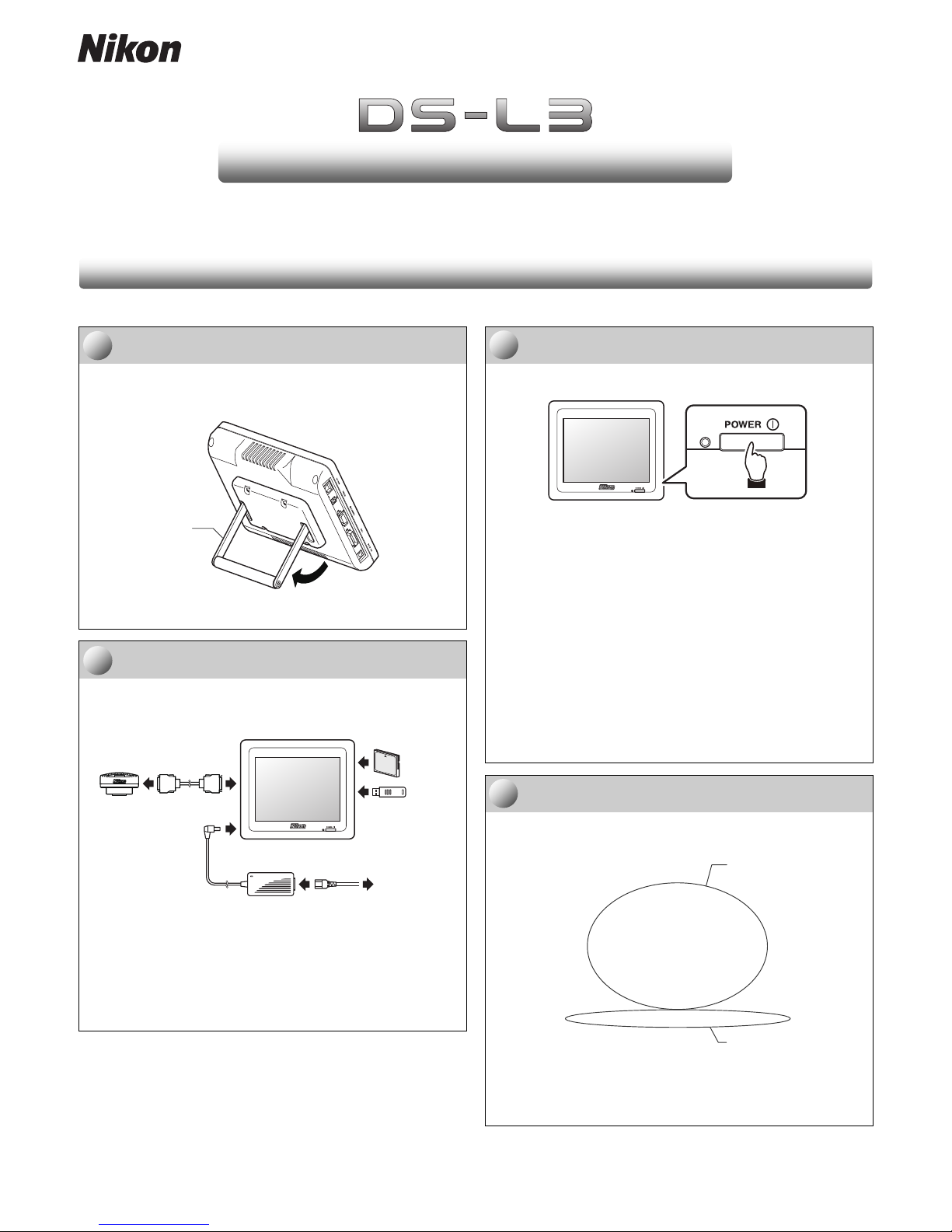
Set the DS-L3 at the desired position.
Install the DS-L3 on a level surface of a desk, etc., with its stand
arm open, and adjust the stand arm angle.
Using the stand arm
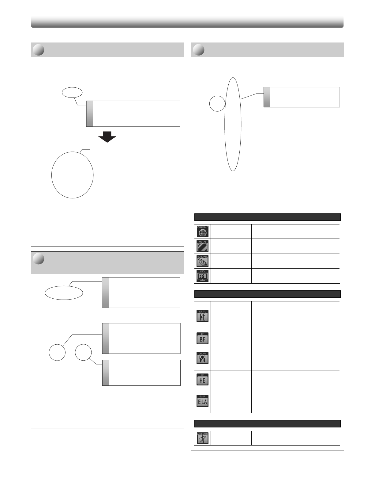
Connect the DS-L3 with peripheral devices.
Connect a DS camera head and the AC adapter to the DS-L3,
and insert a CF card or USB memory stick.
CF CARD
Connecting the DS-L3 and peripheral devices
Note: When plugging the power cord, be sure that:
• all other connections are setup; and
• the power cord is connected directly to the AC socket
(100-240 VAC).
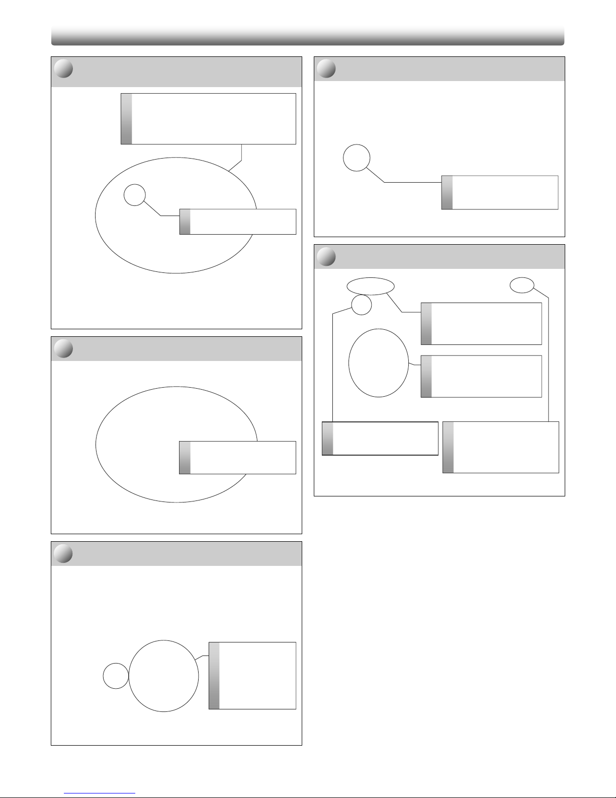
Switch on the power to the DS-L3.
Push the POWER switch on the front of the DS-L3 to turn it on.
Operating the POWER switch
When the power is on, the POWER indicator lights up, and the
start screen is displayed on the monitor for a few seconds.
Start screen
Check the monitor for the live image.
After the start screen, the task bar and the live image from the
DS camera head are shown on the monitor.
Live image on the monitor
Note: The live image may be unclear depending on the
settings or conditions of the optical device.
M555 E 11.9.NF.1 (2/3)
QQuuiicckk RReeffeerreennccee
SSeettuupp aanndd SSttaarrttuupp ooff DDSS--LL33
A
djust the angle
of the stand arm.
Task bar
1
1
1
2
2
2
3
3
3
4
4
4
DS camera
head
T o AC socket
AC adapter
USB
memory
stick
CF card
DS-L3
DS camera
cable
Check for the live image.
Page 2
2
This section describes a simple procedure to capture and view an image.
Open the [CAMERA MENU: CAMERA] screen.
[CAMERA MENU] is used for image capture operation.
Displaying [CAMERA MENU]
Specify a save drive, a folder, and a recording
mode.
[CAMERA MENU: SHOT/REC] screen
Note: For details of the setup procedure, see “8.3.4 Setting
Items of the [CAMERA MENU: SHOT/REC] Screen” in
the “Camera Operation” instruction manual.
Select a scene mode.
Select a scene mode for the subject.
Selecting a scene mode (on any [CAMERA MENU] screen)
Note: Scene mode options shown on the [SCENE/CSM]
submenu depends on the setting for the [SCENE
SELECT] button of the [SETUP MENU: MAIN] screen.
[
IND ]
Wafer/IC chip Suitable for capturing a wafer or IC chip.
Metal ceramic
Suitable for capturing a metal specimen
or ceramic or plastic subject.
Circuit board
Suitable for capturing a high-contrast
subject such as a circuit board or metal.
FPD (Flat Panel
Display)
Suitable for capturing the color filters for
flat display devices.
[
BIO ]
Dark field /
fluorescent
Suitable for capturing a dark subject. The
camera gain (sensitivity) is improved for
focusing to reduce time to display. When
used with the [E MODE] button, noise in
the acquired image data is minimized.
Bright field Used for general stained specimens.
Differential
interference
contrast /
phase contrast
Contrast is enhanced for differential
interference and phase contrast
photography.
HE staining
This mode is provided for photographing
of HE stained specimen. It is optimized
for color reproduction specific to HE.
Enzyme labeled
antibody method
This mode is provided for photographing
of ELISA (Enzyme labeled antibody
method). It is optimized for color
reproduction specific to DAB.
[
OTHERS ]
Asbestos
This mode is used to photograph the
asbestos specimens.
BBaassiicc CCaappttuurree OOppeerraattiioonn
1
2
3
Specify a storage media and a
folder.
Press the [DRIVE] button and
select the desired storage media
and the folder.
Specify a recording mode.
Press the [REC MODE] button
and select the desired image
source, image size, and file type.
Open the [CAMERA MENU:
SHOT/REC] screen.
Press the menu selection button
to open the submenu and select
[SHOT/REC].
Select a scene mode.
Press the [SCENE/CSM] button
and select the desired mode.
[CAMERA MENU: CAMERA] screen
1
1
1
2
2
2
3
3
3
Open the [CAMERA MENU: CAMERA]
screen.
Press the [CAM] button on the task bar to
open the [CAMERA MENU] screen.
Page 3
3
Set the white balance.
(for a color DS camera head only)
[CAMERA MENU] screen (same appearance for all menus)
Note: When the white balance setting is done, a “WB
COMPLETED” message is displayed.
Check the subject with the live image.
Adjust the layout and focus.
[CAMERA MENU] screen (same appearance for all menus)
Perform exposure compensation.
To adjust the brightness of the subject, use the exposure
compensation control shown by pressing the [EXP CMP] button.
Exposure can be controlled within the range of ±2.0 and by 1/3.
Press the [OK] button to finish the setting.
Setting the exposure compensation
(on any [CAMERA MENU] screen)
Capture an image.
Press the [CAPTURE] button to save the displayed image.
You hear a capture sound when capturing an image. When the
image file is saved, “SAVED 1/1” is displayed on the task bar.
[CAMERA MENU] screen (same appearance for all menus)
View the saved image.
[VIEW MENU] screen
BBaassiicc CCaappttuurree OOppeerraattiioonn <<ccoonnttdd..>>
6
6
6
Perform exposure
compensation.
Press the [EXP
CMP] button and
control the exposure
value with the slider
and buttons.
4
4
4
1
Prepare an evenly white subject such as a
sheet of paper.
Prepare an evenly white subject such as a
sheet of paper, and place it so that the entire
photographing scope is covered by the subject.
2
Set the white balance.
Press the [White BL] button.
7
7
7
8
8
8
Capture an image.
Press the [CAPTURE] button
to save the image.
3
4
2
Select the desired image file.
Select a file you want to view
from the list of saved image
files.
1
Open the [VIEW MENU] screen.
Press the menu selection
button to open the submenu
and select [VIEW].
Check the subject.
View the live image and
check the subject.
5
5
5
V
iew the image.
Press the [PLAY] button to
view the selected image.
Stop image viewing.
Press the [X] button on the
top right to stop viewing the
selected image and return to
the live image.
Page 4

4
This section describes how to overlay scales and annotations with text or straight/curved lines to the image.
Open the [TOOL MENU] screen.
[TOOL MENU] is used for annotation operation.
[CAMERA MENU]
[TOOL MENU]
Displaying the [TOOL MENU] screen
Select a registered calibration setting.
Specifying a calibration setting ([TOOL MENU] screen)
Note: For details of calibration registration, see “11.2.4
Registering Calibration Values” in “Camera Operation”
instruction manual.
Specify the unit.
[TOOL SET: MAIN]
Specifying the unit ([TOOL SET: MAIN] screen)
AAnnnnoottaattiioonn ((SSccaalleess aanndd TTeexxtt CCoommmmeenntt))
2
Open the [TOOL MENU]
screen.
Press the menu select
button to open the
submenu, and select
[TOOL].
You can access the
following buttons from
[TOOL MENU]:
Scales
• XY measurement
• X scale (cross scale)
• Scale
• Cross hairs
• Grid
Annotation
• Text
• Straight line
• Pen
• Marker
3
2
1
3
3
3
2
2
2
1
1
1
1
Select a calibration
setting.
Press the [CALIB] button
to open the submenu and
select the desired
calibration setting.
Open the [TOOL SET:
MAIN] screen.
Press the [TOOL SET]
button on the [TOOL
MENU] screen to open
the submenu and select
[MAIN].
Specify the unit.
Press the [UNIT] button
on the [TOOL SET:
MAIN] screen to open the
submenu and select the
desired unit.
Return to [TOOL MENU].
After selecting the unit,
press the [
TOOL]
button to return to the
[TOOL MENU] screen or
press the [X] button to
close the [TOOL SET:
MAIN] screen.
Open the [CAMERA MENU: CAMERA]
screen.
Press the [CAM] button on the task bar to
open the [CAMERA MENU] screen.
Page 5

5
Operate scales and annotation functions.
Note: Color for drawing can be selected from black, red,
yellow, green, blue, and white.
Scales
XY measurement
Movable two cross lines are
displayed on the screen.
Horizontal (X) and vertical (Y)
distance can be measured.
X : 3.00 mm
Y : 2.00 mm
X scale (cross scale)
Movable two cross lines are
displayed on the screen.
Horizontal (X) and vertical (Y)
distance can be measured.
0
1mm
0
1mm
0
1mm
0
1mm
Scale
A scale is displayed at the
bottom right of the screen.
Approximate size of an object
can be measured.
Cross hairs
Movable cross hairs with
concentric circles are
displayed. Settings of cross
hairs and circles can be
changed in [TOOL SET: X
HAIRS] screen.
Grid
Grid can be displayed on the
screen. Distance between grid
lines can be arbitrarily specified
with a numeric value or by two
points on the screen (in [TOOL
SET: GRID] screen).
Annotation
Text comment
An alphanumeric text comment
can be added to an arbitrary
location of the screen.
Straight line and arrow
A straight line or arrow can be
drawn on the screen.
Pen drawing
Any line can be drawn on the
screen.
Counting with marker
A marker with a number can be
drawn on an arbitrary location
of the screen. Points on the
screen can be numbered for
the color.
Configure to paste scales and annotations to
the image.
[TOOL SET: MAIN]
[TOOL SET: MAIN] screen
A
dd a text comment to
the desired position.
AAnnnnoottaattiioonn ((SSccaalleess aanndd TTeexxtt CCoommmmeenntt)) <<ccoonnttdd..>>
4
3
1
Open the [TOOL SET: MAIN]
screen.
Press the [TOOL SET] button
on the [TOOL MENU] screen
to open the submenu and
select [MAIN].
2
Note: An image can be captured or
printed with scales and
annotations overlaid just as
displayed on the monitor, if
they are set to be output by
selecting with the checkmark.
5
5
5
4
4
4
Return to [TOOL MENU].
After the settings is done, press
the [
TOOL] button to go back
to the [TOOL MENU] screen or
press the [X] button to close the
[TOOL SET: MAIN] screen.
Paste annotations to the image.
Put a checkmark to the
[OVERLAY] checkbox.
(This applies to overlaying the
measurement results.)
Paste scales to the image.
Select the desired item(s) by
putting a checkmark to its box.
Page 6

6
This section describes how to measure a length, angle, diameter or circumference of a circle, or polygon area, etc. on the monitor.
Open the [TOOL BAR] screen.
[TOOL BAR] is used for measurement.
Single-row button display
Two-row button display
Switching [TOOL BAR] display
Select a registered calibration setting.
Specifying a calibration setting ([TOOL BAR] screen)
Note: For details of calibration registration, see “11.2.4
Registering Calibration Values” in “Camera Operation”
instruction manual.
Specify the unit.
[TOOL SET: MAIN]
Specifying the unit ([TOOL SET: MAIN] screen)
MMeeaassuurreemmeenntt
Press to show the lower row of buttons.
Press to hide the lower row of buttons.
2
2
2
1
1
1
Open the [TOOL BAR] window.
Press the [T.BAR] button on the
task bar to open [TOOL BAR].
Select a registered
calibration setting.
Press the calibration
button in the lower row of
[TOOL BAR] to open the
submenu and select the
desired calibration
setting.
3
2
1
3
3
3
Open the [TOOL SET:
MAIN] screen.
Press the [TOOL SET]
button on the [TOOL
MENU] screen to open
the submenu and select
[MAIN].
Specify the unit.
Press the [UNIT] button
on the [TOOL SET:
MAIN] screen to open the
submenu and select the
desired unit.
Return to [TOOL MENU].
After selecting the unit,
press the [
TOOL]
button to return to the
[TOOL MENU] screen or
press the [X] button to
close the [TOOL SET:
MAIN] screen.
Page 7

7
Use the [TOOL BAR] buttons to perform
measurement on the monitor.
Note: Color for drawing can be selected from black, red,
yellow, green, blue, or white.
Distance between two points
Measures the distance
between the two points (e.g.,
A-B) specified on an image.
Perpendicular line
Measures the length of a
perpendicular line drawn from a
point (e.g., c) to a reference line
(e.g., A-B) drawn between two
points on an image.
Angle
Measures the angle between
two straight lines (e.g., A-B and
C-D) drawn on the screen.
Diameter and circumference
Measures the diameter and
circumference of a circle drawn
with three points (e.g., A, B, C)
on the circumference.
Polygon area
Measures the area of a polygon
(e.g., A-D) drawn on the
screen. To define the polygon
after specifying the points,
press the [AREA
MEASUREMENT] button.
Distance between two circle centers
Measures the distance
between centers of two circles
(e.g., A-C, D-F) each drawn
with three points on
circumference.
Pitch length
Measures the length of several
perpendicular lines drawn from
desired points (e.g., C, D) to a
reference line drawn between
the two points (e.g., A-B) and
distance between points (pitch
distance).
Operate the measurement results.
Use buttons on the [TOOL BAR] for the following operations.
Operating measurement results ([TOOL BAR] screen)
Configure to paste measurement results to
the image.
[TOOL SET: MAIN]
([TOOL SET: MAIN] screen)
Clear / clear all the measurement results
Update measurement results
Output measurement results
to CSV format
Show/hide
measurement
results overlay
Abort/undo
measurement
MMeeaassuurreemmeenntt <<ccoonnttdd..>>
6
6
6
3
2
1
Note: An image can be captured or
printed with measurement
results overlaid just as
displayed on the monitor, if
they are set to be output by
selecting with the checkmark.
5
5
5
4
4
4
Open the [TOOL SET: MAIN]
screen.
Press the [TOOL SET] button
on the [TOOL MENU] screen
to open the submenu and
select [MAIN].
Return to [TOOL MENU].
After the settings is done, press
the [
TOOL] button to go back
to the [TOOL MENU] screen or
press the [X] button to close the
[TOOL SET: MAIN] screen
Paste measurement results
to the image.
Put a checkmark to the
[OVERLAY] checkbox.
(This applies to overlaying the
annotations.)
Page 8

8
This section describes the initial setting procedure in minimal steps. Perform the procedure when you use the DS-L3 for the first time.
Open the [SETUP MENU: MAIN] screen.
[SETUP MENU] is used for initial settings.
Displaying [SETUP MENU]
Select a language and a scene mode.
[SETUP MENU: MAIN] screen
Open the [SETUP MENU: ADDITIONAL]
screen.
Switching the setup menu
Set the current date and image save
destination.
[SETUP MENU: ADDITIONAL] screen
Close the [SETUP MENU] screen.
Closing the [SETUP MENU] screen
IInniittiiaall SSeettttiinnggss
1
1
1
Open [SETUP MENU: ADDITIONAL].
Press the menu select button to open the
submenu and select [ADD].
2
2
2
3
3
3
4
4
4
5
5
5
1
2
3
Set the current date and time.
Specify the current date and time in two
digits in the [DATE/TIME SET] area.
1
2
3
Save the settings.
Press the [SAVE] button
to apply the settings.
Select the desired scene mode.
Press the [SCENE SELECT]
button to open the submenu and
select a scene mode from [BIO],
[IND], and [OTHERS].
Select a language.
Press the [LANG] button and select the
desired language from [ENG] (English) and
[日本語] (Japanese).
Quit [SETUP MENU].
Press the [X] button to close
[SETUP MENU].
Specify the save destination.
Select the save destination from
[SAVE TO MEDIA] and [SAVE
TO SERVER] in the [CAPTURE
FUNCTION] area. [SAVE TO
MEDIA] is selected by default.
Save the settings.
Press the [SAVE] button
to apply the settings.
Open the [SETUP MENU] screen.
Press the [SETUP] button on the task bar
to open [SETUP MENU] screen.
 Loading...