

Page 1

デジスコーピングブラケットDSB-N1
Digiscoping Bracket DSB-N1
Jp
En
Es
Fr
De
It
Se
Nl
Ru
Pt
Pl
Fi
No
Dk
Cz
Ro
Hu
使用説明書
/ Instruction manual / Manual de instrucciones / Mode d'emploi /
Bedienungsanleitung / Manuale di istruzioni / Bruksanvisning / Handleiding /
Инструкция по эксплуатации / Manual de instruções / Instrukcja obsługi /
Käyttöopas / Brukerveiledning / Instruktionsvejledning / Příručka uživatele /
Manual de instrucţiuni / Használati utasítás
Page 2

このたびは、デジスコーピングブラケットDSB-N1をお買い上げいただきまして、ありがとうござい
Jp
ます。
ご使用前に、この使用説明書をよくお読みの上、正しくお使いください。
•
お読みになったあとは、製品のそばなど、いつも手元に置いてご使用ください。
•
仕様・外観などは改善のため予告なしに変更する場合があります。
•
本「使用説明書」に掲載されている文章・イラスト等の無断転載を禁じます。
•
アフターサービスについて
お買い上げいただきましたデジスコーピングブラケットDSB-N1を、安心してご愛用いただきますよ
う、次のとおり修理、アフターサービスを行っております。
本製品の補修用性能部品(その製品の機能を維持するために必要な部品)は、製造打ち切り後も5年間を目安に保
•
有しております。ご使用いただいております製品が修理可能かどうかにつきましては、ご購入店、またはニコンの
サービス機関へお問い合わせください。
ニコンのサービス機関につきましては、「ニコンサービス機関のご案内」をご覧ください。
•
水没、火災、落下等による故障または破損で全損と認められる場合は、修理が不可能となります。なお、この故障
※
または破損の程度の判定はニコンのサービス機関におまかせください。
安全上・使用上のご注意
安全にお使いいただくために必ずお守りください。
誤った使い方をしたときに生じる危害や損害の程度を、次の表示で区分し、説明しています。
■
警告
注意
「死亡または重傷などを負う可能性が想定される」
内容です。
「傷害を負う可能性または物的損害のみが発生する可能性が想定される」
内容です。
警告
DSB-N1単体または組み合わせた状態のカメラで直射日光や強い光を見ないでください。
•
注意
直射日光の当たる所に、この製品を長時間保管しないでください。
•
小さなお子さまの手の届くところに、梱包箱、梱包材や付属品などを置かないでください。
•
歩行中にこの製品を使用しないでください。
•
本機を組み込んだままの移動は、脱落等の恐れがありますので行わないでください。
•
可動部が多くあります。調整つまみや固定つまみの役目・機能を十分に理解してからご使用ください。
•
金属を組み合わせた製品ですので、指を挟み込んだり、けがなどをされないよう十分注意してお取り扱いください。
•
お子様がご使用されるときは特にご注意ください。
Jp
2
3
Page 3

Jp
acb
付属品
ケーブルレリーズ×1本
•
滑り止めパッド×2個
•
遮光ゴムシート×1枚
•
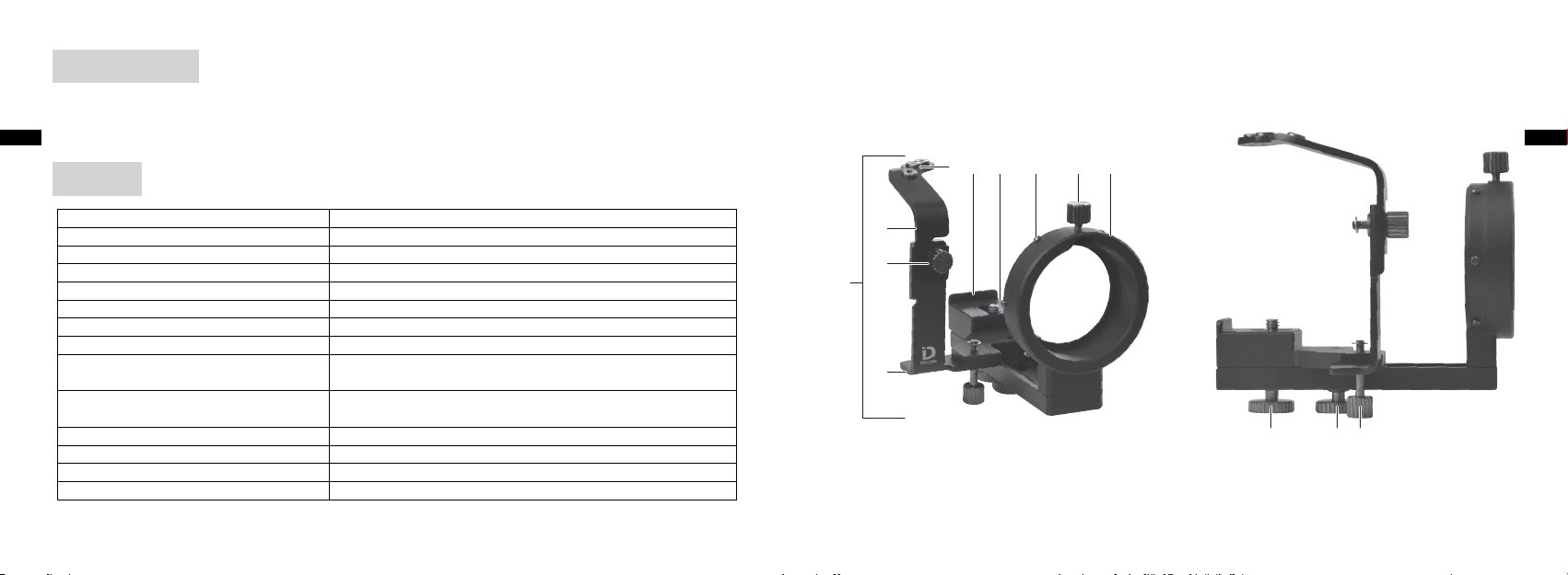
各部名称と機能
本体 デジスコーピングブラケットDSB-N1本体
1
レリーズ台A ケーブルレリーズの位置を調整する台
2
レリーズ台A取り付けつまみ
3
レリーズ台B
4
レリーズ取り付け穴 ケーブルレリーズを取り付ける穴(3カ所)
5
カメラ取り付け台突起部 カメラの背面部を合わせる突起部
6
カメラ取り付け台 カメラを1本体に取り付ける台
7
遮光ゴムシート取り付け部 遮光ゴムシートを取り付ける凸部(6カ所)
8
DS接眼レンズ取り付けつまみ
9
接眼レンズ(DSマウント)挿入部 接眼レンズのDSマウント部を差し込む挿入部
0
カメラ固定ネジ カメラを7カメラ取り付け台に固定するネジ
a
スライド固定つまみ カメラの位置(前後)を固定するつまみ
b
レリーズ台B取り付けつまみ
c
各部の機能を十分に理解してから、ご使用ください。
4
各部名称 説 明
レリーズ台Aと4レリーズ台Bを固定するつまみ
2
レリーズ台Aを取り付ける台
2
接眼レンズ(DSマウント)挿入部を接眼レンズに固定するつまみ
0
(DSマウント:本製品を取り付けるマウントのこと)
レリーズ台Bを本体に固定するつまみ
4
Jp
56 7 8 9 0
2
3
1
4
5
Page 4

Jp
対応機種について
(2012年9月現在)
撮影について
Jp
対応カメラ:
Nikon1V1、Nikon1J1、Nikon1J2
対応カメラレンズ:
1NIKKORVR10-30mmf/3.5-5.6
1NIKKOR11-27.5mmf/3.5-5.6
1NIKKOR18.5mmf/1.8
対応フィールドスコープ:
EDG85VR/EDG85-AVR/EDG85/EDG85-A/EDG65/EDG65-A/ED82/ED82-A/
EDIII/EDIII-A/III/III-A/ED50/ED50-A
対応接眼レンズ:
FEP-20W、FEP-30W、FEP-38W、FEP-50W、FEP-75W、FEP-25LER
16×ワイド/24×ワイド/30×ワイドDS
27×ワイド/40×ワイド/50×ワイドDS
40×ワイド/60×ワイド/75×ワイドDS
対応携帯型実体顕微鏡:ファーブルフォトEX
※最新の対応カメラ、カメラレンズ、フィールドスコープ、接眼レンズ、携帯型実体顕微鏡などの情
報については、以下のホームページをご確認ください。
http://www.nikonvision.co.jp/
6
露出:
[測光モード]を[中央部重点測光]にすることをおすすめします。[マルチパターン測光]または[スポット測光]
•
にすると、適正露出を得られない場合があります。
•
デジスコーピングシステムは、カメラ用交換レンズとは光学特性が異なるため、露出レベルはご使用のカメラによっ
て異なることがあります。必要に応じて、露出補正のうえ、ご使用お願い致します。特に、ズームの短焦点距離では、
露出補正が必要になる場合があります。
フォーカス:
撮影時のピント調整は、カメラの液晶モニターまたはビューファインダーを見ながら、フィールドスコープのフォー
•
カスリングの調整で仮ピント出しを行い、最終ピントはカメラのフォーカス機能で行ってください。
•
以下の場合、ピント合わせが難しくなります。必要に応じて、Nikon1の液晶の設定を変えてください。
-望遠側の撮影でファインダー像が暗い場合
-被写体が暗い場合
レリーズ:
付属のケーブルレリーズを使用する際は、静かに押してください。強く押し込みすぎるとカメラの設定位置が傾く
•
ことがあります。
高倍率撮影のため、ケーブルレリーズ、セルフタイマーやリモコンを使用してブレを防止してください。
•
7
Page 5

Jp
b
取り付け
注) ○番号・名称は「各部名称と機能」に準じます。
注) つまみ、ネジは全て、反時計回りが「緩む」、時計回りが「締
める」になります。
準備
1. カメラのシャッターボタンに滑り止めパッドを貼り付けます
(図1)。
2. フィールドスコープを三脚に設置します。
3.cレリーズ台B取り付けつまみを緩め、4レリーズ台Bを
本体から取り外します(図2)。
1
本体の取り付け
1.1本体をDS接眼レンズに取り付けます。
DS接眼レンズ取り付けつまみを緩め、0接眼レンズ(DS
図1
図2
4
1
c
9
マウント)挿入部を、しっかり奥まで突き当たるまで挿入し
ます。
押し付けた状態で9DS接眼レンズ取り付けつまみで固定し
ます(図3)。
[注意事項]
接眼レンズ(DSマウント)挿入部が、確実にDSマウント
0
へ取り付けられているか、必ず確認してください。しっかり
と固定されていない状態でカメラの取り付けを行うと、カメ
ラの重みで落下する恐れがあります。
2.bスライド固定つまみを緩め、7カメラ取り付け台を図4で
示す位置までスライドさせて仮止めします。
9
0
1
図3
図4
7
Jp
8
9
Page 6

Jp
カメラの取り付け
1. カメラの電源をONにして、ズーム操作を行い、カメラのレ
ンズ先端を最も繰り出した状態にします(図5)。
2.カメラを1本体に取り付けます。
カメラ取り付け台に載せ、カメラ背面部を6カメラ取り付
7
け台突起部に突き当てて、ぴったりと合わせます。
カメラ固定ネジをカメラの三脚ネジ穴にねじ込み、仮止め
a
します(図6)。
[注意事項]
傾斜タイプのフィールドスコープへの取り付け時は、カメラ
が自重でスライドするため、カメラのレンズ先端と接眼レン
ズや0接眼レンズ(DSマウント)挿入部と接触しないよう
にカメラを手で持ち、注意して行ってください。
図5
図6
6
1
7
a
光軸の調整
1.
カメラのズーム操作を行い、ズームを広角側の状態にします。
カメラの液晶モニター、またはビューファインダーを見なが
2.
ら、画像の中心に接眼レンズの円の中心が重なるように、調
整します。
カメラの電源を入れた時、図Aのように、カメラの視野に対
してフィールドスコープの視界が右(または左)ずれている
場合、カメラの角度を微調整
にします。
光軸の調整後、aカメラ固定ネジを締め、カメラを固定します。
bスライド固定つまみを緩め、カメラごと前方に移動させ、
3.
図Cのように4隅のケラレの大きさが等しく、視界周辺が鮮
明になる位置にカメラを固定します。図Dはまだ鮮明になっ
ていない状態の例です。組み合わせにより図Cにならない場
合もあります。
図Eの状態の場合は、カメラの角度が、まだ左にずれている
状態です。aカメラ固定ネジを緩め、図Cの状態になるよう
にカメラの角度を微調整してください
(図F)
して図Bのような状態
(図F)
。
図A 図B
図C 図D
図E 図F
Jp
10
11
Page 7

Jp
b
7
[注意事項]
光軸調整を行う場合は、カメラのレンズと接眼レンズの接触
•
を防ぐため、カメラのレンズ先端と0接眼レンズ(DSマウン
ト)挿入部の間は、約3mm以上近づけないようにしてくださ
い(図8)。
傾斜タイプのフィールドスコープで光軸調整を行う場合は、
•
カメラが自重でスライドするため、カメラのレンズ先端と接
眼レンズや0接眼レンズ(DSマウント)挿入部と接触しない
ようにカメラを手で持ち、注意して行ってください。
0
0
3mm
図7
a
図8
レリーズ台の取り付け
注) ケーブルレリーズを使用しない場合は次の作業は必要あり
ません。
レリーズ台Aには2つの溝があります。カメラにより3レリー
2
ズ台A取り付つまみを取り付ける溝を変えます。上がJ1/J2用、
下がV1用です(図9)。
1.4レリーズ台Bの3レリーズ台A取り付つまみを緩め、
レリーズ台Aの高さを選択し、3レリーズ台A取り付けつ
まみを締めます(図10)。
2.cレリーズ台B取り付けつまみを緩め、4レリーズ台Bを
カメラ取り付け台下部の凹み部に入れます(図11)。
7
3.cレリーズ台B取り付つまみを締め、4レリーズ台Bを本
体に固定します(図11)。
取り外す時は、cレリーズ台B取り付つまみを緩め、4レ
リーズ台Bを引き抜きます。
2
4
2
J1/J2
V1
図10
2
3
4
図11
4
c
図9
Jp
12
13
Page 8

Jp
ケーブルレリーズの取り付け
レリーズ台Aにはネジ穴があります。カメラにより、ケーブル
2
レリーズを取り付けるネジ穴を変えます(図12)。
左がJ1/J2用、中央がV1用です。
1. ケーブルレリーズの先端を5レリーズ取り付け穴にねじ込み
ます(図13)。
2.ケーブルレリーズを押したときに、ケーブルレリーズ先端が、
カメラのシャッターボタンの中央にくるようします。
レリーズ台A取り付つまみ、またはcレリーズ台B取り付
3
つまみを緩め、2レリーズ台A、または4レリーズ台Bを微
調整します(図14)。
遮光ゴムシートの取り付け
付属の遮光ゴムシートは、カメラに入り込む日差し等の光を軽減
するために必要に応じて使用します。
1.遮光ゴムシートの穴を8遮光ゴムシート取り付け部に引っ掛
けます(図15)。
[注意事項]
遮光ゴムシートを装着した後にカメラ位置を前方向に再調整
したり、ズーム操作する際には、カメラのレンズと接眼レン
ズや0接眼レンズ(DSマウント)挿入部との接触に注意し
てください。
14
8
2
J1/J2 V1
図12
図13
5
2
2
8
図14
3
図15
撮影上のご注意
撮影に使用する三脚は、ゆれが少なく、剛性かつ安定性の高いものを使用してください。
•
取り付ける接眼レンズとの組み合わせ、取り付け位置やズーム位置などの条件により、ケラレや影が生じることが
•
あります。
ケラレや影は取りきれない場合もあります。最低限になるよう、慎重に最適な位置に設定してください。
•
カメラのオートフォーカスが決まらないときは、フォーカスロックの状態でフィールドスコープのフォーカスリン
•
グの再調整でカメラの液晶モニターまたは、ビューファインダーによるピント合わせを行ってください。
高倍率の撮影となりますので、被写界深度が浅くなります。ピント合わせは十分注意してください。
•
液晶モニター及び撮影画像上で外部光の映り込みが確認できるときは、マウントとカメラレンズの隙間に入る外部
•
光を付属の遮光ゴムシートなどでさえぎるようにしてください。取りきれない場合は、黒い布などで全体を覆うよ
うにしてください。
カメラ操作で位置がずれることがあります。シャッターを押す前にケラレや影の状態を確認してください。
•
撮影の際はフラッシュを使わないでください。
•
Nikon1の手ブレ補正はOFFの状態で撮影を行ってください。
•
撮影条件により、画像上に線状のノイズが発生する場合があります。
•
カメラの電池と記憶メディアの交換は、カメラの機種によっては、取り外して行うものと、取り外さなくても可能
•
なものがあります。いずれの場合も取り付け位置の再調整が必要となります。
Jp
15
Page 9

Jp
お手入れについて
水やお湯で洗わないでください。
•
本体の汚れは、柔らかい清潔な布で軽く拭いてください。
•
ベンジン、シンナーなどの有機溶剤や、有機溶剤を含むクリーナーなどは使わないでください。
•
製品仕様
寸法(最小時) 101mm(幅)×106mm(高さ)×127mm(奥行き)(突起物は含まず)
質量(重さ) 270g(付属品は含まず)
※合成焦点距離の計算式は以下を参照ください。
合成焦点距離=接眼レンズ倍率×撮影レンズの焦点距離(35mm判換算ではこの2.7倍)
Jp
16
17
Page 10

THANK YOU FOR PURCHASING THE DIGISCOPING BRACKET DSB-N1.
Thoroughly read this instruction manual before using the product, and be sure to use the product correctly.
•
En
After reading, retain this instruction manual so that it can be easily referenced.
•
Specifications and design are subject to change without notice.
•
No production in any form of this manual, in whole or in part (except for brief quotation in critical articles or reviews), may
•
be made without written authorization from NIKON VISION CO., LTD.
SAFETY AND OPERATION PRECAUTIONS
In order to ensure the safe use of this product, read this manual carefully and be sure you understand the information provided before attempting to operate the product.
The following marks are used to indicate the degrees of injury or damage that could result from misuse of this
■
product.
WARNING
This indication alerts you to the fact that any improper use resulting from ignoring the
contents described herein can result in potential death or serious injury.
This indication alerts you to the fact that any improper use resulting from ignoring the
CAUTIONS
contents described herein can result in potential injury or may cause only a material
loss.
WARNING
Do not look at direct sunlight or intense light through the Digiscoping Bracket DSB-N1 or the lens of the camera mounted
•
with the Digiscoping Bracket DSB-N1.
CAUTIONS
Do not store the product in places exposed to direct sunlight for a long time.
•
Make sure that the packaging box, packing materials, and supplied item(s), etc., are out of reach of children.
•
Do not use this product while walking.
•
Do not move the product mounted to the camera, or otherwise the product may drop off.
•
The product incorporates many movable parts. Make sure that you fully understand the roles and functions of all adjust-
•
ment knobs and fixing knobs before use.
•
The product consists of assembled metal parts. Pay sufficient attention to the handling of the product so that that you will
not pinch your fingers or receive an injury. Pay utmost attention if a child uses the product.
En
18
19
Page 11

Supplied item(s)
acb
En
Cable release × 1
•
Non-skid pad × 2
•
Light shielding rubber sheet × 1
•
Overview
En
56 7 8 9 0
Body (bracket) Digiscoping Bracket DSB-N1
1
Shutter release base A Adjusts the position of the cable release
2
Attaching knob for shutter release base A Fixes 2 shutter release base A and 4 release base B
3
Shutter release base B Mounts 2 shutter release base A
4
Cable release socket Socket for cable release to be screwed into (three holes)
5
Projection on camera attaching base Aligns the rear part of the camera
6
Camera attaching base Mounts the camera to 1 bracket
7
Attaching projections for light
8
shielding rubber sheet
Attaching knob for DS eyepiece Fixes 0 eyepiece (DS mount) insertion to the eyepiece
9
Eyepiece (DS mount) insertion A part to insert the DS mount of the eyepiece
0
Camera fixing screw Fixes the camera with 7 camera attaching base
a
Slide fixing knob Fixes the camera position backward and forward
b
Attaching knob for shutter release base B Fixes 4 shutter release base B with the Digiscoping Bracket
c
Be sure to understand the functions of the product before use.
Nomenclature Description
Projections to attach the rubber shielding sheet (six projections)
(DS mount: A mount to attach the product)
20
2
3
1
4
21
Page 12

Applicable models
En
(as of September 2012)
Applicable cameras:
Nikon 1 V1, Nikon 1 J1, and Nikon 1 J2
Applicable camera lens:
1 NIKKOR VR 10-30 mm f/3.5-5.6
1 NIKKOR 11-27.5 mm f/3.5-5.6
1 NIKKOR 18.5 mm f/1.8
Applicable fieldscopes:
EDG85 VR/EDG85-A VR/EDG85/EDG85-A/EDG65/EDG65-A/ED82/ED82-A/
EDIII/EDIII-A/III/III-A/ED50/ED50-A
Applicable eyepieces:
FEP-20W, FEP-30W, FEP-38W, FEP-50W, FEP-75W, and FEP-25LER
16 × wide/24 × wide/30 × wide DS
27 × wide/40 × wide/50 × wide DS
40 × wide/60 × wide/75 × wide DS
* For the latest information on the applicable cameras, camera lenses, fieldscopes, and eyepieces, refer to
Nikon’s website.
Shooting
Exposure:
It is recommended to set [Metering] to [Center-weighted]. Optimal exposure may not be obtained if [Matrix] or [Spot] is set.
•
The Digiscoping System differs in optical properties from interchangeable lenses. Therefore, the exposure level may vary
•
with each camera. Make exposure compensation if necessary. A short focal length for zooming, in particular, may require
exposure compensation.
Focus:
At the time of shooting, make focus adjustments by turning the focus ring of the fieldscope while seeing the object on the
•
LCD monitor or viewfinder of the camera, and make fine adjustments with the AF (autofocus) function of the camera.
It will be difficult to make focus adjustments in the following cases. Make LCD setting changes for Nikon 1 if necessary.
•
- If the image in the viewfinder is dark at the time of telephoto shooting
- If the object is dark
Shutter release:
Gently press the provided cable release, if used. Do not press the shutter release too strongly, or otherwise the set position
•
of the camera may tilt.
Use a cable release, self-timer, or remote control to prevent vibration because of high-magnification shooting.
•
En
22
23
Page 13

Attaching
b
En
Note) Refer to the circled numbers on the "Overview" page.
Note) All knobs and screws are loosened when they are turned
counterclockwise and tightened when they are turned
clockwise.
Preparing
1. Attach a non-skid pad on the shutter release button of the camera. (Fig. 1)
2. Mount the fieldscope to the tripod.
3. Loosen c attaching knob for shutter release base B and
dismount 4 shutter release base B from 1 bracket. (Fig. 2)
Digiscoping Bracket
1. Mount 1 bracket to the DS eyepieces.
Fig. 1
Fig. 2
4
1
c
Loosen 9 attaching knob for DS eyepiece and insert 0
eyepiece (DS mount) insertion all the way until the end. While
pressing against the insertion, fix the insertion with 9 attaching
knob for DS eyepiece. (Fig. 3)
[Note]
Make sure that 0 eyepiece (DS mount) insertion is securely
attached to the DS mount. If the insertion is not fixed securely,
the camera mounted may fall because of its own weight.
2. Loosen b slide fixing knob, slide 7 camera attaching base
to the position shown in Fig. 4, and temporarily screw down the
camera attaching base.
9
0
Fig. 3
1
En
Fig. 4
7
24
25
Page 14

Attaching the camera
En
1. Turn on the camera, operate the zoom button, and extend the
camera lens to the utmost extended position. (Fig. 5)
2. Attach the camera to 1 bracket.
Mount the camera to 7 camera attaching base and align the
rear part of the camera to 6 projection on camera attaching
base.
Screw a camera fixing screw into the tripod hole and
temporarily secure the camera with the tripod. (Fig. 6)
[Note]
The camera slides because of its own weight if the fieldscope of
angled body type is mounted. Therefore, carefully handle the
fieldscope so that the front of the camera lens will not come in
contact with the eyepiece or 0 eyepiece (DS mount) insertion.
Fig. 5
Fig. 6
6
1
7
a
Adjusting the optical axis
1.
Operate the zoom button and set the zoom to the wide setting
side.
2. While viewing the LCD monitor or the viewfinder of the camera,
make adjustments so that the circle of the eyepiece aligns with
the center of the image.
When turning on the camera, if what you see is like Fig. A, the
field of view of the fieldscope is out of alignment to the right (or
left) relative to the camera. Make fine adjustments of the camera
angle (see Fig. F) until it looks like Fig. B.
After adjusting the optical axis, loosen a camera fixing screw
and fix camera.
3. Loosen b slide fixing knob and move the camera together
with the slide fixing knob forward, and fix the camera where the
field of view is clear and four corners of vignetting are about the
same size as in Fig. C. Fig. D is an example of the field of view not
being clear enough. Depending on your combination, it may not
appear as in Fig. C.
If it appears like Fig. E, the camera is misaligned to the left.
Loosen a camera fixing screw, and make fine adjustments to
the camera position so that it will be in the state of Fig. C. (Fig. F)
Fig. A Fig. B
En
Fig. C Fig. D
Fig. E Fig. F
26
27
Page 15

[Note]
b
7
En
In order to prevent the camera lens from coming in contact with the
•
eyepiece, make sure that the front of the camera lens is not closer than
approximately 3 mm (0.1 in) to 0 eyepiece (DS mount) insertion. (Fig. 8)
The camera slides because of its own weight in the case of adjusting the
•
optical axis while the fieldscope of angled body type is in use. Therefore,
carefully handle the fieldscope so that the front of the camera lens will
not come in contact with the eyepiece or 0 eyepiece (DS mount)
insertion.
0
0
3 mm (0.1 in)
Fig. 7
a
Fig. 8
Attaching the shutter release base
Note) The following steps are unnecessary if the cable release is not
used.
There are two grooves on 2 shutter release base A. Select the
correct groove where 3 attaching knob for shutter release
base A is attached, according to the camera in use. The groove
on the upper side is for J1/J2 and the one on the lower side is
for V1. (Fig. 9)
1. Loosen 3 attaching knob for shutter release base A on 4
shutter release base B, select the height of 2 shutter release
A, and tighten 3 attaching knob for shutter release base A.
(Fig. 10)
2. Loosen c attaching knob for shutter release base B and
insert 4 shutter release base B into the recess at the bottom
of 7 camera attaching base. (Fig. 11)
3. Tighten c attaching knob for shutter release base B and fix
shutter release base B to the bracket. (Fig. 11) To take out
4
shutter release base B, loosen c attaching knob for shutter
release base B and pull out 4 shutter release base B.
2
2
3
4
Fig. 10
J1/J2
V1
4
Fig. 9
En
Fig. 11
4
c
28
29
Page 16

Attaching the cable release
En
There are two screw holes on 2 shutter release base A. Select the
correct screw hole where the cable release is attached, according to
the camera in use. (Fig. 12)
The screw hole on the left-hand side is for J1/J2 and the one in the
middle is for V1.
1. Screw the end of the cable release into 5 cable release socket.
(Fig. 13)
2. After pressing the cable release, make adjustments so that the
end of the cable release will be located in the middle of the
camera’s shutter release button.
Loosen 3 attaching knob for shutter release base A or c
attaching knob for shutter release base B, and make fine
adjustments to 2 shutter release base A or 4 shutter release
base B. (Fig. 14)
Attaching the light shielding rubber sheet
The supplied light shielding rubber sheet is used as needed to reduce
sunlight or other light that enters the camera.
1. Hook the holes of the light shielding rubber sheet onto 8 attach-
ing projections for light shielding rubber sheet. (Fig. 15)
[Note]
Make sure that the camera lens will not come in contact with the
eyepiece or 0 eyepiece (DS mount) insertion at the time of
readjusting the camera position in the forward direction or operating the zoom after the light shielding rubber sheet is attached.
30
8
2
J1/J2 V1
Fig. 12
8
Fig. 13
5
2
2
Fig. 14
3
Fig. 15
Shooting precautions
Use a sturdy tripod to minimize shaking when taking photos.
•
Vignetting or shadows may result depending on relevant conditions, such as the camera model and the type of eyepiece to
•
be attached or the attaching position or zoom position of the camera.
Vignetting or shadows may not be perfectly eliminated. Carefully make optimum position settings in order to minimize
•
vignetting and shadows.
If you cannot focus on the subject using the AF function, lock the AF and set the focus again using the focus ring of the
•
fieldscope while viewing the LCD monitor or viewfinder of the camera.
A shallow depth of field will result because of high-magnification shooting. Pay sufficient attention to focusing.
•
If you notice external light on the LCD monitor or image (picture), use the supplied light shielding rubber sheet to prevent
•
light entering between the mount and lens of the camera. If light still enters, cover the whole equipment with a shield such
as a black cloth.
The camera position may become misaligned during camera operation. Before releasing the shutter, confirm the existence
•
of vignetting and shadows and adjust the camera if necessary.
Do not use the flash when shooting.
•
When shooting, select the vibration reduction function OFF from the Nikon 1 menu.
•
Noise in the form of lines may appear in pictures depending on the shooting condition.
•
When replacing the batteries or recording media, the camera may or may not need to be removed from the connected
•
equipment depending on the camera. In any case, readjustments to the mounting position are necessary.
En
31
Page 17

Storage and cleaning
En
Do not wash the product with cold or hot water.
•
Gently wipe off dirt from the product by using a soft, clean cloth.
•
Do not use organic solvents, such as benzine or paint thinner, or cleaning solution that contains any organic solvents.
•
Product specifications
En
Dimensions
(when folded)
Mass (weight)
* Refer to the following expression for synthetic focal length calculation.
Synthetic focal length = Magnification of eyepiece × Focal length of shooting lens (2.7× in the case of 35mm
(1.4in) conversion)
101 (W) × 106 (H) x 127 (D) mm (without screws)
4.0 (W) × 4.2 (H) × 5.0 (D) in (without screws)
270 g (without supplied item(s))
9.5 oz (without supplied item(s))
32
33
Page 18

GRACIAS POR ADQUIRIR EL SOPORTE DE DIGISCOPING DSB-N1.
Antes de utilizar el producto, lea detenidamente este manual de instrucciones y asegúrese de utilizar el producto correcta-
•
mente.
Es
Una vez leído, guarde este manual de instrucciones para posteriores consultas.
•
Las especificaciones y el diseño están sujetos a cambios sin previo aviso.
•
No se permite la reproducción de este manual de ninguna forma, ni total ni parcialmente (salvo en breves referencias en
•
artículos o revisiones importantes), sin la previa autorización por escrito de NIKON VISION CO., LTD.
PRECAUCIONES DE SEGURIDAD Y FUNCIONAMIENTO
Con el fin de garantizar el uso seguro de este producto, lea atentamente este manual y asegúrese de que comprende la información en él facilitada antes de intentar utilizar el producto.
Las indicaciones siguientes se utilizan para mostrar la importancia de las lesiones o daños derivados de un uso
■
indebido de este producto.
ADVERTENCIA
Esta indicación le advierte sobre el hecho de que cualquier uso indebido que ignore el
contenido aquí descrito, puede ocasionar posibles lesiones graves o incluso la muerte.
Esta indicación le advierte sobre el hecho de que cualquier uso indebido que
PRECAUCIONES
ignore el contenido aquí descrito, puede ocasionar posibles lesiones o únicamente una pérdida de material.
ADVERTENCIA
No mire a la luz directa del sol o a una luz intensa a través del Soporte de Digiscoping DSB-N1 o del objetivo de la cámara
•
que se monta con el Soporte de Digiscoping DSB-N1.
PRECAUCIONES
No guarde el producto en lugares expuestos a la luz directa del sol durante mucho tiempo.
•
Asegúrese de que la caja de embalaje, los materiales de embalaje y artículo(s) suministrado(s), se encuentran fuera del
•
alcance de los niños.
•
No utilice este producto mientras camina.
•
No desplace el producto que se ha montado en la cámara; de lo contrario, se podría soltar.
•
El producto incorpora muchas piezas móviles. Asegúrese de que entiende perfectamente los mecanismos y funciones de
todas las perillas de ajuste y fijación antes de su utilización.
•
El producto está formado por piezas metálicas ensambladas. Preste especial atención cuando manipule el producto para no
pillarse los dedos o sufrir una lesión. Preste atención absoluta en el caso de que un niño utilice el producto.
Es
34
35
Page 19

Artículo(s) suministrado(s)
acb
Disparador por cable × 1
•
Es
Alfombrilla antideslizante × 2
•
Funda de goma de protección de la luz × 1
•
Es
Información general
Cuerpo (soporte) Soporte de Digiscoping DSB-N1
1
Base del disparador A Ajusta la posición del disparador por cable
2
Perilla de acoplamiento de la base del disparador A
3
Base del disparador B Monta la 2 base del disparador A
4
Rosca del disparador por cable Rosca en la que se va a atornillar el disparador por cable (tres orificios)
5
Saliente en la base de acoplamiento de la cámara
6
Base de acoplamiento de la cámara Monta la cámara en el 1 soporte
7
Salientes de acoplamiento para la
8
funda de goma de protección de la luz
Perilla de acoplamiento del ocular DS Fija la inserción del 0 ocular (montura DS) en el ocular
9
Inserción del ocular (montura DS) Una pieza que permite insertar la montura DS del ocular
0
Tornillo de fijación de la cámara Fija la cámara con la 7 base de acoplamiento de la cámara
a
Perilla de fijación de deslizamiento Fija la posición de la cámara hacia atrás y hacia adelante
b
Perilla de acoplamiento de la base del disparador B
c
Asegúrese de que entiende las funciones del producto antes de utilizarlo.
Nomenclatura Descripción
Fija la 2 base del disparador A y la 4 base del disparador B
Alinea la parte posterior de la cámara
Salientes para acoplar la funda de goma de protección de la luz (seis
salientes)
(Montura DS: una montura de acoplamiento del producto)
Fija 4 la base del disparador B con el Soporte de Digiscoping
36
56 7 8 9 0
2
3
1
4
37
Page 20

Modelos correspondientes
Es
Cámaras correspondientes:
(a partir de septiembre de 2012)
Nikon 1 V1, Nikon 1 J1 y Nikon 1 J2
Objetivo de cámara correspondiente:
1 NIKKOR VR 10-30 mm f/3,5-5,6
1 NIKKOR 11-27,5 mm f/3,5-5,6
1 NIKKOR 18,5 mm f/1,8
Fieldscopes correspondientes:
EDG85 VR/EDG85-A VR/EDG85/EDG85-A/EDG65/EDG65-A/ED82/ED82-A/
EDIII/EDIII-A/III/III-A/ED50/ED50-A
Oculares correspondientes:
FEP-20W, FEP-30W, FEP-38W, FEP-50W, FEP-75W y FEP-25LER
DS de 16 × de ancho/24 × de ancho/30 × de ancho
DS de 27 × de ancho/40 × de ancho/50 × de ancho
DS de 40 × de ancho/60 × de ancho/75 × de ancho
* Para obtener información sobre las cámaras, objetivos de cámara, fieldscopes y oculares correspondientes
más recientes, consulte el sitio web de Nikon.
Disparo
Exposición:
Se recomienda configurar [Medición] en [Ponderada central]. Es posible que no se obtenga una exposición óptima si se
•
configura [Matricial] o [Puntual].
El sistema Digiscoping presenta diferencias en cuanto a las propiedades ópticas de los objetivos intercambiables. Por lo
•
tanto, el nivel de exposición puede variar según la cámara. Aplique una compensación de exposición, si fuera necesario. En
concreto, una distancia focal corta para el zoom puede precisar una compensación de exposición.
Enfoque:
En el momento del disparo, aplique ajustes de enfoque girando el anillo de enfoque del fieldscope mientras visualiza el
•
objeto en la pantalla LCD o en el visor de la cámara, y aplique ajustes de precisión con la función AF (autofoco) de la cámara.
Será difícil aplicar ajustes de enfoque en los casos siguientes. Aplique cambios en la configuración de la pantalla LCD para
•
Nikon 1, si lo estima necesario.
- Si la imagen del visor es oscura en el momento del disparo de teleobjetivo
- Si el sujeto es oscuro
Disparador:
Presione suavemente el disparador por cable suministrado, si se utiliza. No presione el disparador aplicando demasiada
•
fuerza; de lo contrario, se podría inclinar la posición de ajuste de la cámara.
Utilice un disparador por cable, disparador automático o control remoto para evitar las vibraciones ocasionadas por el
•
disparo de gran aumento.
Es
38
39
Page 21

Acoplamiento
b
Es
Nota: consulte los números que aparecen rodeados por un círcu-
lo en la página «Información general».
Nota: todas las perillas y tornillos se aflojan cuando se giran hacia
la izquierda y se aprietan cuando se giran hacia la derecha.
Preparación
1. Acople una alfombrilla antideslizante en el disparador de la cámara. (Fig. 1)
2. Monte el fieldscope en el trípode.
3. Afloje la c perilla de acoplamiento de la base del disparador
B y desmonte la 4 base del disparador B del 1 soporte. (Fig. 2)
Soporte de Digiscoping
1. Monte el 1 soporte en los oculares DS.
Fig. 1
Fig. 2
4
1
c
Afloje la 9 perilla de acoplamiento del ocular DS e introduzca
la 0 inserción del ocular (montura DS) por completo. Mientras
presiona la inserción, fíjela con la 9 perilla de acoplamiento del
ocular DS. (Fig. 3)
[Nota]
Asegúrese de que se acopla firmemente la 0 inserción del ocu-
lar (montura DS) en la montura DS. En caso contrario, la cámara
montada se podría caer por su propio peso.
2. Afloje la b perilla de fijación de deslizamiento, deslice la 7
base de acoplamiento de la cámara hacia la posición mostrada
en la Fig. 4 y atornille provisionalmente la base de acoplamiento
de la cámara.
9
0
Fig. 3
Es
1
Fig. 4
7
40
41
Page 22

Acoplamiento de la cámara
1. Encienda la cámara, utilice el botón del zoom y amplíe el objetivo
Es
de la cámara a la posición máxima de aumento. (Fig. 5)
2. Acople la cámara en el 1 soporte.
Monte la cámara en la 7 base de acoplamiento de la cámara
y alinee la parte posterior de la cámara con el 6 saliente de la
base de acoplamiento de la cámara.
Atornille el a tornillo de fijación de la cámara en el orificio del
trípode y fije provisionalmente la cámara con el trípode. (Fig. 6)
[Nota]
La cámara se desliza por su propio peso si se monta el fieldscope
del tipo de cuerpo en ángulo. Por lo tanto, manipule el fieldscope
con cuidado de modo que la parte delantera del objetivo de la
cámara no entre en contacto con el ocular o con la 0 inserción
del ocular (montura DS).
Fig. 5
Fig. 6
6
1
7
a
Ajuste del eje óptico
1.
Utilice el botón del zoom y configure el zoom en el ajuste máximo.
2. Mientras visualiza la pantalla LCD o el visor de la cámara, aplique
ajustes para que el círculo del ocular se alinee con el centro de la
imagen.
Al encender la cámara, si lo que aparece es como la Fig. A, es por-
que el campo de visión del fieldscope no está alineado hacia la
derecha (o izquierda) con respecto a la cámara. Aplique ajustes
de precisión en el ángulo de la cámara (consulte la Fig. F) hasta
que aparezca como la Fig. B.
Una vez se ha ajustado el eje óptico, afloje el a tornillo de
fijación de la cámara y fije la cámara.
3. Afloje la b perilla de fijación de deslizamiento, desplace hacia
adelante la cámara junto con la perilla de fijación de deslizamiento y fije la cámara en un punto en que el campo de visión
sea claro y las cuatro esquinas de viñeteado tengan aproximadamente el mismo tamaño que en la Fig. C. La Fig. D es un ejemplo
que muestra un campo de visión no demasiado claro. En función
de la combinación, es posible que no aparezca como en la Fig. C.
Si aparece como en la Fig. E, es porque la cámara no está bien
alineada a la izquierda. Afloje el a tornillo de fijación de la
cámara y aplique ajustes de precisión en la posición de la cámara
de modo que aparezca como en la Fig. C. (Fig. F)
Fig. A Fig. B
Es
Fig. C Fig. D
Fig. E Fig. F
42
43
Page 23

[Nota]
b
7
Para evitar que el objetivo de la cámara entre en contacto con el ocular,
•
Es
asegúrese de que la distancia de la parte delantera del objetivo de la
cámara con la 0 inserción del ocular (montura DS) no sea superior a
unos 3 mm(0,1 pulg.). (Fig. 8)
•
La cámara se desliza por su propio peso si se ajusta el eje óptico mientras se utiliza el fieldscope del tipo de cuerpo en ángulo. Por lo tanto,
manipule el fieldscope con cuidado de modo que la parte delantera
del objetivo de la cámara no entre en contacto con el ocular o con la 0
inserción del ocular (montura DS).
0
0
3 mm(0,1 pulg.)
Fig. 7
a
Fig. 8
Acoplamiento de la base del disparador
Nota: los siguientes pasos son innecesarios si no se utiliza el dispara-
dor por cable.
Existen dos ranuras en la 2 base del disparador A. Seleccione
la ranura correcta en la que se acopla la 3 perilla de acopla-
miento de la base del disparador A, conforme a la cámara que
se utilice. La ranura de la parte superior es para J1/J2 y la ranura
de la parte inferior es para V1. (Fig. 9)
1. Afloje la 3 perilla de acoplamiento de la base del dispara-
dor A en la 4 base del disparador B, seleccione la altura del
disparador A y apriete la 3 perilla de acoplamiento de la
2
base del disparador A. (Fig. 10)
2. Afloje la c perilla de acoplamiento de la base del dispara-
dor B e introduzca la 4 base del disparador B en la hendi-
dura de la parte inferior de la 7 base de acoplamiento de la
cámara. (Fig. 11)
3. Apriete la c perilla de acoplamiento de la base del dispara-
dor B y fije la 4 base del disparador B en el soporte.
(Fig. 11) Para extraer la base del disparador B, afloje la c perilla
de acoplamiento de la base del disparador B y extraiga la 4
base del disparador B.
2
2
3
4
Fig. 10
J1/J2
V1
4
Es
Fig. 11
4
c
Fig. 9
44
45
Page 24

Acoplamiento del disparador por cable
Existen dos orificios de tornillo en la 2 base del disparador A.
Es
Seleccione el orificio de tornillo adecuado en el que se va a acoplar el
disparador por cable, conforme a la cámara que se utilice. (Fig. 12)
El orificio de tornillo de la izquierda es para J1/J2 y el orificio de tornillo del medio es para V1.
1. Atornille el extremo de disparador por cable en la 5 rosca del
disparador por cable. (Fig. 13)
2.
Una vez se ha presionado el disparador por cable, aplique ajustes para
que el extremo de este se sitúe en el medio del disparador de la cámara.
Afloje la 3 perilla de acoplamiento de la base del disparador
A o la c perilla de acoplamiento de la base del disparador B y
aplique ajustes de precisión en la 2 base del disparador A o la
base del disparador B. (Fig. 14)
4
Acoplamiento de la funda de goma de protección de la luz
La funda de goma de protección de la luz suministrada se utiliza, según sea necesario, para reducir la entrada de la luz del sol u otro tipo de luz en la cámara.
1. Enganche los orificios de la funda de goma de protección de la luz
en los 8 salientes de acoplamiento de la funda de goma de
protección de la luz. (Fig. 15)
[Nota]
Asegúrese de que el objetivo de la cámara no entra en contacto
con el ocular o la 0 inserción del ocular (montura DS) al reajustar
la posición de la cámara en la dirección de avance o utilizar el zoom
una vez se ha acoplado la funda de goma de protección de la luz.
46
8
2
J1/J2 V1
Fig. 12
8
Fig. 13
5
2
2
Fig. 14
3
Fig. 15
Precauciones relativas al disparo
Utilice un trípode resistente para minimizar las sacudidas al tomar fotografías.
•
El efecto de viñeteado o las sombras pueden resultar adecuados en función de las condiciones relevantes, como el modelo
•
de cámara y tipo de ocular que se vaya a incorporar, o la posición de acoplamiento o posición del zoom de la cámara.
Es posible que no se pueda eliminar totalmente el efecto de viñeteado o las sombras. Aplique con cuidado los ajustes de
•
posición más adecuados con el fin de minimizar el viñeteado y las sombras.
Si no puede enfocar el sujeto con la función AF, bloquee el AF y configure nuevamente el enfoque utilizando el anillo de
•
enfoque del fieldscope mientras visualiza la pantalla LCD o el visor de la cámara.
Se obtendrá una profundidad de campo debido a un disparo de gran aumento. Preste especial atención al enfoque.
•
Si observa una luz exterior en la pantalla LCD o en la imagen (fotografía), utilice la funda de goma de protección de la luz
•
suministrada para evitar que la luz penetre entre la montura y el objetivo de la cámara. Si la luz sigue entrando, cubra todo
el equipo con una protección, como un paño de color negro.
La alineación de la posición de la cámara podría verse afectada durante el funcionamiento de la cámara. Antes de accionar
•
el obturador, confirme la existencia de viñeteado y sombras, y ajuste la cámara si fuera necesario.
No utilice el flash al disparar.
•
Al fotografiar, seleccione DESACTIVADO para la función de reducción de vibración en el menú Nikon 1.
•
Puede aparecer ruido en forma de líneas en las imágenes en función de la condición de disparo.
•
Al sustituir las baterías o soportes de grabación, es posible que se deba o no extraer la cámara del equipo conectado en
•
función de la cámara. En cualquier caso, se deberá reajustar la posición de montaje.
Es
47
Page 25

Almacenamiento y limpieza
Es
No lave el producto con agua fría o caliente.
•
Limpie suavemente la suciedad del producto utilizando un paño suave y limpio.
•
No utilice disolventes orgánicos, como bencina o disolvente de pintura, o una solución de limpieza que contenga disolven-
•
tes orgánicos.
Especificaciones del producto
Es
Dimensiones
(al plegarse)
Masa (peso)
* Consulte la siguiente expresión para realizar el cálculo de la distancia focal efectiva.
Distancia focal efectiva = Aumento del ocular × Distancia focal del objetivo de disparo (2,7 × para la conversión
de formato de 35 mm (1,4 pulg.))
101 (An) × 106 (Al) × 127 (P) mm (sin tornillos)
4,0 (An) × 4,2 (Al) × 5,0 (P) pulg. (sin tornillos)
270 gr. (sin artículo(s) suministrado(s))
9,5 onzas (sin artículo(s) suministrado(s))
48
49
Page 26

NOUS VOUS REMERCIONS D'AVOIR ACHETÉ LE SUPPORT POUR DIGISCOPIE DSB-N1.
Lisez attentivement ce mode d'emploi avant d'utiliser le matériel, et assurez-vous de l'utiliser correctement.
•
Après l'avoir lu, conservez ce mode d'emploi pour pouvoir vous y reporter plus tard.
•
Les caractéristiques et la conception du produit peuvent être modifiées sans notification préalable.
•
Fr
Ce manuel ne peut être reproduit sous quelque forme que ce soit, en partie ou en totalité (sauf pour de brèves citations
•
dans des articles de critique ou d'essai), sans l'autorisation écrite de NIKON VISION CO., LTD.
PRÉCAUTIONS DE SÉCURITÉ ET D'UTILISATION
Pour utiliser ce matériel en toute sécurité, lisez attentivement ce manuel et assurez-vous d'avoir bien compris
les informations fournies avant de l'employer.
Les repères suivants indiquent la gravité des blessures ou des dommages pouvant résulter d'une mauvaise
■
utilisation de ce matériel.
AVERTISSEMENT
Cette indication vous alerte sur le fait qu'un usage impropre et contraire à
l'avertissement est susceptible d'entraîner des blessures graves, voire fatales.
Cette indication vous alerte sur le fait qu'un usage impropre et contraire à
ATTENTION
l'avertissement est susceptible d'entraîner des blessures, ou de simples pertes
matérielles.
AVERTISSEMENT
Ne regardez pas directement le soleil ou une lumière vive à travers le support pour digiscopie DSB-N1, ou l'objectif de
•
l'appareil photo monté sur ce dernier.
ATTENTION
Ne stockez pas longtemps le matériel dans un endroit exposé à la lumière directe du soleil.
•
Ne laissez pas la boîte d'emballage, les matériaux d'emballage et les éléments fournis à la portée des enfants.
•
N'utilisez pas le matériel en marchant.
•
Ne déplacez pas le support monté sur l'appareil photo, car il risquerait de tomber.
•
Ce produit contient de nombreuses pièces mobiles. Assurez-vous d'avoir bien compris le rôle et le fonctionnement de
•
toutes les molettes de réglage et de fixation avant utilisation.
Ce produit est constitué d'un assemblage de pièces métalliques. Lors de sa manipulation, prenez toutes les précautions
•
utiles pour ne pas vous pincer les doigts ou vous blesser. Soyez extrêmement vigilant si un enfant utilise le matériel.
Fr
50
51
Page 27

Éléments fournis
acb
Câble déclencheur × 1
•
Patin antidérapant × 2
Fr
•
Écran d'occultation en caoutchouc × 1
•
Vue d'ensemble
Fr
56 7 8 9 0
Corps (support) Support pour digiscopie DSB-N1
1
Base A du déclencheur Ajuste la position du câble déclencheur
2
Molette de fixation pour base A du déclencheur
3
Base B du déclencheur Se monte sur la base A 2 du déclencheur
4
Raccord du câble déclencheur Raccord dans lequel se visse le câble déclencheur (trois trous)
5
Cale sur socle de fixation de l'appareil photo
6
Socle de fixation de l'appareil photo Reçoit l'appareil photo à monter sur le support
7
Ergots de fixation de l'écran
8
d'occultation en caoutchouc
Molette de fixation d'oculaire DS
9
Pièce d'insertion d'oculaire (monture DS) Pièce où vient s'insérer la monture DS de l'oculaire
0
Vis de fixation de l'appareil photo Fixe l'appareil photo à son socle
a
Molette de fixation coulissante Permet de déplacer l'appareil photo vers l'avant ou l'arrière et de le
b
Molette de fixation pour base B du déclencheur
c
Assurez-vous de comprendre le fonctionnement du matériel avant de l'utiliser.
52
Nomenclature Description
Assemble la base A 2 et la base B 4 du déclencheur
Permet de caler l'arrière de l'appareil photo
1
Six ergots permettant de fixer l'écran d'occultation en caoutchouc
Fixe la pièce d'insertion d'oculaire (monture DS) 0 à l'oculaire lui-même
(monture DS : monture à assembler au support)
7
bloquer en position
Fixe la base B 4 du déclencheur au support pour digiscopie
2
3
1
4
53
Page 28

Modèles compatibles
(à compter de septembre 2012)
Prise de vue
Appareils photo compatibles :
Fr
Nikon 1 V1, Nikon 1 J1 et Nikon 1 J2
Objectif compatible :
1 NIKKOR VR f 10-30 mm/3,5-5,6
1 NIKKOR 11-27,5 mm f/3,5-5,6
1 NIKKOR 18,5 mm f/1,8
Lunettes d'observation compatibles :
EDG85 VR/EDG85-A VR/EDG85/EDG85-A/EDG65/EDG65-A/ED82/ED82-A/
EDIII/EDIII-A/III/III-A/ED50/ED50-A
Oculaires compatibles :
FEP-20W, FEP-30W, FEP-38W, FEP-50W, FEP-75W et FEP-25LER
Systèmes de digiscopie à grossissement 16× / 24× / 30×
Systèmes de digiscopie à grossissement 27× / 40× / 50×
Systèmes de digiscopie à grossissement 40× / 60× / 75×
* Pour les dernières informations en date sur les appareils photo, objectifs, lunettes d'observation et oculaires
compatibles, veuillez vous reporter au site internet de Nikon.
54
Exposition :
Il est recommandé de régler la [Mesure] sur [Pondérée centrale]. Si l'on choisit [Matricielle] ou [Spot], l'exposition risque de
•
ne pas être optimale.
Par ses propriétés optiques, le système de digiscopie diffère des objectifs interchangeables. Par conséquent, le niveau
•
d'exposition peut varier d'un appareil photo à l'autre. Si nécessaire, corrigez l'exposition. En particulier, une focale courte
destinée à zoomer peut exiger une correction d'exposition.
Mise au point :
Au moment de la prise de vue, effectuez la mise au point en tournant la bague de la lunette et en regardant simultanément
•
le sujet sur l'écran ACL ou dans le viseur de l'appareil photo, puis affinez la mise au point avec la fonction AF (autofocus) de
l'appareil photo.
La mise au point sera difficile dans les cas suivants. Si nécessaire, modifiez le réglage ACL sur le Nikon 1.
•
- Si l'image dans le viseur est sombre lors d'une prise de vue au téléobjectif.
- Si le sujet lui-même est sombre.
Déclenchement de l'obturateur :
Si vous utilisez le câble déclencheur fourni, pressez-le délicatement. N'appuyez pas trop fort sur le déclencheur, car cela
•
pourrait faire pencher l'appareil photo et fausser sa position.
Pour les prises de vue à fort grossissement, utilisez un câble déclencheur, un retardateur ou une télécommande afin d'éviter
•
les vibrations.
Fr
55
Page 29

Fixation
b
Remarque) Les numéros encerclés sont décrits à la page "Vue
Fr
d'ensemble".
Remarque) Toutes les vis et molettes se dévissent dans le sens
anti-horaire et se vissent dans le sens horaire.
Préparation
1.
Fixez un patin antidérapant sur le déclencheur de l'appareil photo.
(Fig. 1)
2. Montez la lunette d'observation sur le trépied.
3. Dévissez la molette de fixation de la base B du déclencheur c
et démontez la base B du déclencheur 4 du support 1. (Fig. 2)
Support pour digiscopie
1. Montez le support 1 sur l'oculaire DS.
Fig. 1
Fig. 2
4
1
c
Dévissez la molette de fixation d'oculaire DS 9 et insérez à
fond la pièce d'insertion d'oculaire (monture DS) 0. Tout en
appuyant dessus, fixez l'insertion à l'aide de la molette de
fixation d'oculaire DS 9. (Fig. 3)
[Remarque]
Vérifiez que la pièce d'insertion d'oculaire (monture DS) 0 est
solidement fixée à la monture DS, faute de quoi l'appareil photo
monté risquerait de tomber son l'effet de son poids.
2. Desserrez la molette de fixation coulissante b, faites coulisser
le socle de fixation de l'appareil photo 7 jusqu'à la position
illustrée sur la Fig. 4 et vissez-le provisoirement.
9
0
Fig. 3
Fr
1
Fig. 4
7
56
57
Page 30

Fixation de l'appareil photo
1. Mettez l'appareil photo sous tension, actionnez le bouton de
Fr
zoom et placez l'objectif en position d'extension maximale. (Fig. 5)
2. Fixez l'appareil photo au support 1.
Montez l'appareil photo sur son socle de fixation 7 et alignez
l'arrière de l'appareil photo contre la cale de son socle de
fixation 6.
Vissez la vis de fixation d'appareil photo a dans le trou du
trépied pour maintenir provisoirement l'appareil et le trépied.
(Fig. 6)
[Remarque]
Si la lunette installée est de type coudé, l'appareil photo va glisser
sous l'effet de son propre poids. Par conséquent, manipulez la lunette avec précaution de sorte que l'extrémité avant de l'objectif
de l'appareil photo ne touche pas l'oculaire ni la pièce
d'insertion d'oculaire (monture DS) 0.
Fig. 5
Fig. 6
6
1
7
a
Ajustement de l'axe optique
1.
Actionnez le bouton de zoom et tournez le zoom du côté grand
angle.
2. Tout en regardant sur l'écran ACL ou dans le viseur de l'appareil
photo, effectuez les ajustements nécessaires pour que le cercle
de l'oculaire s'aligne au centre de l'image.
Lorsque vous mettez l'appareil photo sous tension, si ce que
vous voyez ressemble à la Fig. A, c'est que le champ de vision de
la lunette est désaxé vers la droite (ou la gauche) par rapport à
l'appareil photo. Ajustez précisément l'angle de l'appareil photo
(voir Fig. F) jusqu'à ce que l'image ressemble à la Fig. B.
Après avoir ajusté l'axe optique, dévissez la vis de fixation de
l'appareil photo a et fixez-le.
3. Dévissez la molette de fixation coulissante b et avancez-la
avec l'appareil photo, puis fixez ce dernier au point où le champ
de vision est clair et les quatre coins de vignettage approximativement de même taille que sur la Fig. C. La Fig. D présente un
exemple de clarté insuffisante du champ de vision. Selon votre
combinaison, il peut être différent de la Fig. C.
S'il ressemble à la Fig. E, l'appareil photo est désaxé vers la gau-
che. Dévissez la vis de fixation d'appareil photo a, et affinez
la position de l'appareil de manière à obtenir l'image de la Fig. C.
(Fig. F)
Fig. A Fig. B
Fr
Fig. C Fig. D
Fig. E Fig. F
58
59
Page 31

[Remarque]
b
7
Pour éviter que l'objectif de l'appareil photo ne touche l'oculaire, veillez
•
à maintenir un écart de 3 mm (0,1 pouce) au moins entre l'extrémité
Fr
avant de l'objectif et la pièce d'insertion d'oculaire (monture DS) 0.
(Fig. 8)
Lorsque l'on ajuste l'axe optique en utilisant une lunette de type coudé,
•
l'appareil photo glisse sous l'effet de son propre poids. Par conséquent,
manipulez la lunette avec précaution de sorte que l'extrémité avant de
l'objectif de l'appareil photo ne touche pas l'oculaire ni la pièce d'inser-
tion d'oculaire (monture DS) 0.
0
0
3 mm (0,1 pouce)
Fig. 7
a
Fig. 8
Fixation de la base du déclencheur
Remarque) Les étapes suivantes ne sont pas nécessaires si l'on n'uti-
lise pas le câble déclencheur.
La base A du déclencheur 2 comporte deux encoches
destinées à recevoir la molette de fixation pour base A du
déclencheur 3. Choisissez l'encoche en fonction de l'appareil
photo utilisé : encoche supérieure pour les modèles J1/J2 et
encoche inférieure pour le modèle V1. (Fig. 9)
1. Dévissez la molette de fixation pour base A du déclencheur
située sur la base B du déclencheur 4, choisissez la hau-
3
teur de la base A du déclencheur 2, et revissez la molette de
fixation pour base A du déclencheur 3. (Fig. 10)
2. Dévissez la molette de fixation pour base B du déclencheur
et insérez la base B du déclencheur 4 dans la cavité
c
prévue à la base du socle de fixation de l'appareil photo 7.
(Fig. 11)
3. Revissez la molette de fixation pour base B du déclencheur
et fixez la base B du déclencheur 4 au support. (Fig. 11)
c
Pour enlever la base B du déclencheur, dévissez la molette de
fixation pour base B du déclencheur c et retirez la base B
du déclencheur 4.
2
2
3
4
Fig. 10
4
Fig. 9
Fr
J1/J2
V1
Fig. 11
4
c
60
61
Page 32

Fixation du câble déclencheur
La base A du déclencheur 2 comporte deux trous de vis destinés à
recevoir le câble déclencheur. Choisissez le trou en fonction de l'appareil photo utilisé : (Fig. 12)
Fr
trou de gauche pour les modèles J1/J2 et central pour le modèle V1.
1. Vissez l'extrémité du câble déclencheur dans la raccord du câble
déclencheur 5. (Fig. 13)
2. Après avoir appuyé sur le câble déclencheur, ajustez-le de sorte
que son extrémité se trouve au milieu du déclencheur de l'appareil photo.
Dévissez la molette de fixation pour base A du déclencheur 3
ou la molette de fixation pour base B du déclencheur c, et
ajustez précisément la base A du déclencheur 2 ou la base B
du déclencheur 4. (Fig. 14)
Fixation de l'écran d'occultation en caoutchouc
L'écran d'occultation en caoutchouc fourni sert à atténuer, si nécessaire, la pénétration de lumière (du soleil ou autre) dans l'appareil photo.
1. Accrochez les œillets de l'écran d'occultation en caoutchouc sur les
ergots de fixation de l'écran d'occultation en caoutchouc 8.
(Fig. 15)
[Remarque]
Veillez à ce que l'objectif de l'appareil photo ne touche pas l'oculaire ni la pièce d'insertion d'oculaire (monture DS) 0 lorsque
vous avancez l'appareil pour réajuster sa position, ou que vous utilisez le zoom après avoir fixé l'écran d'occultation en caoutchouc.
62
8
2
J1/J2 V1
Fig. 12
8
Fig. 13
5
2
2
Fig. 14
3
Fig. 15
Précautions lors de la prise de vue
Servez-vous d'un trépied robuste pour limiter les secousses lors des prises de vue.
•
Un vignettage ou des ombres peuvent apparaître en fonction de paramètres tels que le modèle d'appareil photo, le type
•
d'oculaire monté, la position de fixation et la position du zoom de l'appareil photo.
Il se peut que ces phénomènes ne puissent être totalement éliminés. Optimisez soigneusement la position pour minimiser
•
le vignettage et les ombres.
Si vous ne parvenez pas à mettre au point le sujet en utilisant la fonction AF (autofocus), verrouillez-la et refaites la mise au
•
point en tournant la bague de la lunette et en regardant simultanément le sujet sur l'écran ACL ou dans le viseur de l'appareil photo.
Si le grossissement est important, la profondeur de champ sera faible. Faites alors attention à la mise au point.
•
Si vous observez une lumière extérieure sur l'écran ACL ou sur l'image, utilisez l'écran d'occultation en caoutchouc fourni
•
pour empêcher la lumière de passer entre la monture et l'objectif de l'appareil photo. Si la lumière pénètre malgré tout,
recouvrez tout l'équipement d'un écran - un tissu noir par exemple.
L'utilisation de l'appareil photo peut conduire à fausser son alignement. Avant de déclencher l'obturateur, vérifiez l'absence
•
de vignettage et d'ombres et ajustez si nécessaire la position de l'appareil.
N'utilisez pas le flash lors des prises de vue.
•
Lors de la prise de vue, désactivez la fonction de réduction des vibrations en la plaçant sur DÉSACTIVÉE à partir du menu
•
Nikon 1.
Selon les conditions de prise de vue, un bruit peut apparaître sous forme de lignes sur les photos.
•
Selon l'appareil photo utilisé, il peut être nécessaire (ou non) de le dissocier de l'équipement en place pour changer la
•
batterie ou le support d'enregistrement. Quoi qu'il en soit, la position de montage doit être réajustée.
Fr
63
Page 33

Stockage et nettoyage
Ne lavez pas le support à l'eau chaude ou froide.
•
Dépoussiérez délicatement le support à l'aide d'une lingette douce et propre.
Fr
•
N'utilisez pas de solvant organiques tels que le benzène ou les diluants pour peinture, ni de solution nettoyante contenant
•
des solvants organiques.
Caractéristiques techniques
Fr
Dimensions
(replié)
Poids
* Utilisez cette formule pour calculer la focale effective :
Focale effective = Grossissement de l'oculaire × Focale de l'objectif de prise de vue (× 2,7 pour conversion au
format 35mm (1,4 pouce))
101 (L) × 106 (H) × 127 (P) mm (sans les vis)
4,0 (L) × 4,2 (H) × 5,0 (P) pouces (sans les vis)
270 g (sans les éléments fournis)
9,5 oz (sans les éléments fournis)
64
65
Page 34

VIELEN DANK, DASS SIE SICH FÜR DEN KAUF DES DIGISKOPIE-KAMERATRÄGERS DSB-N1 ENTSCHIEDEN HABEN.
Lesen Sie vor der Verwendung des Produkts diese Bedienungsanleitung sorgfältig durch und verwenden Sie das Produkt
•
richtig.
Bewahren Sie die Bedienungsanleitung nach dem Lesen zum Nachschlagen griffbereit auf.
•
Änderungen der Spezifikationen und des Designs ohne vorherige Ankündigung vorbehalten.
•
De
Die Wiedergabe dieser Bedienungsanleitung in jeglicher Form, ganz oder teilweise, ohne vorherige schriftliche Genehmi-
•
gung durch NIKON VISION CO., LTD. ist untersagt (abgesehen von kurzen Zitaten in Artikeln oder Produktbewertungen).
SICHERHEITS- UND BEDIENUNGSHINWEISE
Lesen Sie zum sicheren Gebrauch des Produkts dieser Bedienungsanleitung sorgfältig durch und vergewissern
Sie sich, dass Sie die bereitgestellten Informationen verstanden haben, bevor Sie das Produkt verwenden.
Die folgenden Kennzeichnungen werden verwendet, um den Schweregrad von Verletzungen oder Beschädi-
■
gungen anzugeben, die durch einen falschen Gebrauch des Produkts verursacht werden können.
Dieser Hinweis macht Sie darauf aufmerksam, dass eine unsachgemäße Verwendung
WARNUNG
des Geräts durch Missachtung des Inhalts dieses Hinweises zum Tod oder zu schweren
Verletzungen führen kann.
Dieser Hinweis macht Sie darauf aufmerksam, dass eine unsachgemäße Verwendung
VORSICHT
des Geräts durch Missachtung des Inhalts dieses Hinweises zu Verletzungen oder Sachschäden führen kann.
WARNUNG
Schauen Sie nicht durch den Digiskopie-Kameraträger DSB-N1 oder das Objektiv der Kamera, mit der der Digiskopie-Kame-
•
raträger DSB-N1 verwendet wird, in direkte Sonneneinstrahlung oder intensives Licht.
VORSICHT
Bewahren Sie das Produkt nicht lange Zeit an Or ten auf, die direkter Sonneneinstrahlung ausgesetzt sind.
•
ergewissern Sie sich, dass sich der Verpackungskarton, die Verpackungsmaterialien und die gelieferten Teile usw. außerhalb der Reichweite von Kindern befinden.
V
•
Verwenden Sie das Produkt nicht während des Gehens.
•
Bewegen Sie die Kamera nicht bei aufgesetztem Produkt, da andernfalls das Produkt herunterfallen kann.
•
Das Produkt umfasst viele bewegliche Teile. Vergewissern Sie sich vor dem Gebrauch, dass Sie die Rollen und Funktionen
•
aller Einstellknöpfe und Feststellknöpfe vollständig verstanden haben.
Das Produkt besteht aus zusammengesetzten Metallteilen. Seien Sie beim Umgang mit dem Produkt vorsichtig, damit Sie
•
sich nicht die Finger einklemmen oder sich verletzen. Seien Sie extrem aufmerksam, wenn ein Kind das Produkt verwendet.
De
66
67
Page 35
Im Lieferumfang
acb
Kabelauslöser × 1
•
Rutschfestes Pad × 2
•
Lichtschutzblende × 1
•
De
Übersicht
De
56 7 8 9 0
Gehäuse (Kameraträger) Digiskopie-Kameraträger DSB-N1
1
Auslöserplatte A Stellt die Position des Kabelauslösers ein
2
Befestigungsknopf für die Auslöserplatte A Fixiert 2 Auslöserplatte A und 4 Auslöserplatte B
3
Auslöserplatte B Befestigt 2 Auslöserplatte A
4
Kabelauslöseranschluss
5
Vorsprung an der Kamerabefestigungsplatte
6
Kamerabefestigungsplatte Befestigt die Kamera am 1 Kameraträger
7
Befestigungsnasen für die
8
Lichtschutzblende
Befestigungsknopf für das DS-Okular Fixiert 0 Okulareinsatz (DS-Anschluss) am Okular
9
Okulareinsatz (DS-Anschluss) Ein Teil zum Einsetzen des DS-Anschlusses des Okulars
0
Kamerafeststellschraube Fixiert die Kamera an der 7 Kamerabefestigungsplatte
a
Schiebefeststellknopf Fixiert die Kameraposition nach hinten und nach vorne
b
Befestigungsknopf für die Auslöserplatte B Fixiert 4 Auslöserplatte B am Digiskopie-Kameraträger
c
Achten Sie darauf, dass Sie die Funktionen des Produkts vor dem Gebrauch verstanden haben.
Bezeichnungen Beschreibung
Anschluss, in den der Kabelauslöser eingeschraubt wird (drei Bohrungen)
Richtet den hinteren Teil der Kamera aus
Nasen zur Befestigung der Lichtschutzblende (sechs Nasen)
(DS-Anschluss: Ein Anschluss zur Befestigung des Produkts)
68
2
3
1
4
69
Page 36

Unterstützte Modelle
(Stand September 2012)
Aufnahme
Unterstützte Kameras:
Nikon 1 V1, Nikon 1 J1 und Nikon 1 J2
De
Unterstütztes Kameraobjektiv:
1 NIKKOR VR 10-30mm f/3,5-5,6
1 NIKKOR 11-27,5mm f/3,5-5,6
1 NIKKOR 18,5mm f/1,8
Unterstützte Beobachtungsfernrohre:
EDG85 VR/EDG85-A VR/EDG85/EDG85-A/EDG65/EDG65-A/ED82/ED82-A/
EDIII/EDIII-A/III/III-A/ED50/ED50-A
Unterstützte Okulare:
FEP-20W, FEP-30W, FEP-38W, FEP-50W, FEP-75W und FEP-25LER
16 × Wide/24 × Wide/30 × Wide DS
27 × Wide/40 × Wide/50 × Wide DS
40 × Wide/60 × Wide/75 × Wide DS
* Aktuelle Informationen zu unterstützten Kameras, Kameraobjektiven, Beobachtungsfernrohren und Okula-
ren finden Sie auf der Nikon-Website.
70
Belichtung:
Es wird empfohlen, [Belichtungsmessung] auf [Mittenbetonte Messung] zu setzen. Die optimale Belichtung wird mögliche-
•
rweise nicht ermittelt, wenn [Matrixmessung] oder [Spotmessung] eingestellt ist.
Das Digiskopie-System unterscheidet sich in seinen optischen Eigenschaften von Wechselobjektiven. Daher kann sich die
•
Belichtung je nach Kamera unterscheiden. Nehmen Sie bei Bedarf eine Belichtungskorrektur vor. Insbesondere bei kurzen
Brennweiten für das Zoomen kann eine Belichtungskorrektur erforderlich sein.
Fokus:
Nehmen Sie bei der Aufnahme Fokuseinstellungen vor, indem Sie den Fokussierring des Beobachtungsfernrohrs drehen,
•
während das Motiv auf dem LCD-Monitor oder im Sucher der Kamera angezeigt wird, und nehmen Sie die Feineinstellung
mit der AF-Funktion (Autofokus) der Kamera vor.
In den folgenden Fällen ist die Fokuseinstellung schwierig. Ändern Sie bei Bedarf die LCD-Einstellung für Nikon 1.
•
- Wenn das Bild im Sucher bei Teleaufnahmen dunkel ist
- Wenn das Motiv dunkel ist
Auslöser:
Drücken Sie vorsichtig den mitgelieferten Kabelauslöser, wenn verwendet. Drücken Sie den Auslöser nicht zu stark, da sich
•
andernfalls die eingestellte Position der Kamera neigen kann.
Verwenden Sie bei starker Vergrößerung einen Kabelauslöser, Selbstauslöser oder eine Fernsteuerung, um Verwacklungen
•
zu verhindern.
De
71
Page 37

Befestigung
b
Hinweis) Informationen zu den Zahlen im Kreis finden Sie auf der
De
Hinweis) Alle Knöpfe und Schrauben werden gelöst, wenn sie
Vorbereitung
1. Befestigen Sie ein rutschfestes Pad auf dem Auslöser der Kamera.
2. Setzen Sie das Beobachtungsfernrohr auf das Stativ.
3. Lösen Sie den c Befestigungsknopf für die Auslöserplatte B
Seite "Übersicht".
entgegen dem Uhrzeigersinn gedreht werden, und festgezogen, wenn sie im Uhrzeigersinn gedreht werden.
(Abb. 1)
und nehmen Sie die 4 Auslöserplatte B vom 1 Kameraträger
ab. (Abb. 2)
Digiskopie-Kameraträger
1. Setzen Sie den 1 Kameraträger auf das DS-Okular.
Abb. 1
Abb. 2
4
1
c
Lösen Sie den 9 Befestigungsknopf für das DS-Okular und
schieben Sie den 0 Okulareinsatz (DS-Anschluss) bis zum Anschlag ein. Drücken Sie gegen den Einsatz und fixieren Sie dabei
den Einsatz mit dem 9 Befestigungsknopf für das DS-Okular.
(Abb. 3)
[Hinweis]
Vergewissern Sie sich, dass der 0 Okulareinsatz (DS-Anschluss)
sicher am DS-Anschluss befestigt ist. Wenn der Einsatz nicht
sicher befestigt ist, kann die aufgesetzte Kamera durch ihr Eigengewicht herunterfallen.
2. Lösen Sie den b Schiebefeststellknopf, schieben Sie die 7
Kamerabefestigungsplatte in die Position wie in Abb. 4 gezeigt
und schrauben Sie die Kamerabefestigungsplatte vorübergehend
fest.
9
0
Abb. 3
1
De
Abb. 4
7
72
73
Page 38

Befestigung der Kamera
1. Schalten Sie die Kamera ein, betätigen Sie die Zoomtaste und
fahren Sie das Kameraobjektiv voll aus. (Abb. 5)
2. Befestigen Sie die Kamera am 1 Kameraträger.
De
Setzen Sie die Kamera auf die 7 Kamerabefestigungsplatte
und richten Sie den hinteren Teil der Kamera am 6 Vorsprung
an der Kamerabefestigungsplatte aus.
Schrauben Sie die a Kamerafeststellschraube in das Stati-
vgewinde und befestigen Sie die Kamera vorübergehend am
Stativ. (Abb. 6)
[Hinweis]
Die Kamera verschiebt sich durch ihr Eigengewicht, wenn ein
Beobachtungsfernrohr mit abgewinkeltem Gehäuse aufgesetzt
ist. Seien Sie beim Umgang mit dem Beobachtungsfernrohr vorsichtig, so dass die Vorderseite des Kameraobjektivs das Okular
bzw. den 0 Okulareinsatz (DS-Anschluss) nicht berührt.
Abb. 5
Abb. 6
6
1
7
a
Einstellung der optischen Achse
1.
Betätigen Sie die Zoomtaste und stellen Sie den Zoom auf Weitwinkel ein.
2. Schauen Sie auf den LCD-Monitor oder durch den Sucher der
Kamera und nehmen Sie die Einstellungen vor, so dass sich der
Kreis des Okulars in der Bildmitte befindet.
Wenn Sie nach dem Einschalten der Kamera ein Bild wie in Abb.
A sehen, befindet sich das Sichtfeld des Beobachtungsfernrohrs
rechts (oder links) von der Achse der Kamera. Nehmen Sie die
Feineinstellung des Kamerawinkels vor (siehe Abb. F), bis sich
ein Bild wie in Abb. B ergibt.
Lösen Sie nach dem Einstellen der optischen Achse die a Ka-
merafeststellschraube und fixieren Sie die Kamera.
3. Lösen Sie den b Schiebefeststellknopf und schieben Sie die
Kamera zusammen mit dem Schiebefeststellknopf nach vorne
und fixieren Sie die Kamera, wenn das Sichtfeld scharf ist und
die vier Ecken der Vignettierung etwa die gleiche Größe wie in
Abb. C haben. In Abb. D ist als Beispiel ein Sichtfeld zu sehen, das
nicht scharf genug ist. Abhängig von Ihrer Kombination kann
das Bild von Abb. C abweichen.
Wenn das Bild Abb. E entspricht, ist die Kamera nach links
verschoben. Lösen Sie die a Kamerafeststellschraube und
nehmen Sie die Feinstellung der Kameraposition vor, so dass ein
Zustand wie in Abb. C erreicht wird. (Abb. F)
Abb. A Abb. B
De
Abb. C Abb. D
Abb. E Abb. F
74
75
Page 39

[Hinweis]
b
7
Damit das Kameraobjektiv nicht das Okular berührt, vergewissern Sie
•
sich, dass die Vorderseite des Kameraobjektivs einen Mindestabstand
von 3 mm (0,1 in) zum 0 Okulareinsatz (DS-Anschluss) hat. (Abb. 8)
De
Die Kamera verschiebt sich durch ihr Eigengewicht, wenn die opti-
•
sche Achse eingestellt wird, während ein Beobachtungsfernrohr mit
abgewinkeltem Gehäuse aufgesetzt ist. Seien Sie beim Umgang mit
dem Beobachtungsfernrohr vorsichtig, so dass die Vorderseite des
Kameraobjektivs das Okular bzw. den 0 Okulareinsatz (DS-Anschluss)
nicht berührt.
0
0
3 mm (0.1 in)
Abb. 7
a
Abb. 8
Befestigung der Auslöserplatte
Hinweis) Die folgenden Schritte sind nicht erforderlich, wenn der
Kabelauslöser nicht verwendet wird.
In der 2 Auslöserplatte A gibt es zwei Aussparungen. Wählen
Sie je nach verwendeter Kamera die richtige Aussparung, in der
der 3 Befestigungsknopf für die Auslöserplatte A befestigt
wird. Die obere Aussparung ist für die J1/J2 und die untere
Aussparung für die V1. (Abb. 9)
1. Lösen Sie den 3 Befestigungsknopf für die Auslöserplatte A
an der 4 Auslöserplatte B, wählen Sie die Höhe der 2 Auslö-
serplatte A und ziehen Sie den 3 Befestigungsknopf für die
Auslöserplatte A fest. (Abb. 10)
2. Lösen Sie den c Befestigungsknopf für die Auslöserplatte B
und schieben Sie die 4 Auslöserplatte B in die Aufnahme auf
der Unterseite der 7 Kamerabefestigungsplatte. (Abb. 11)
3. Ziehen Sie den c Befestigungsknopf für die Auslöserplatte
B fest und fixieren Sie die 4 Auslöserplatte B am Kamera-
träger. (Abb. 11) Zum Abnehmen der Auslöserplatte B lösen
Sie den c Befestigungsknopf für die Auslöserplatte B und
ziehen Sie die 4 Auslöserplatte B heraus.
2
2
3
4
Abb. 10
J1/J2
V1
4
Abb. 9
De
Abb. 11
4
c
76
77
Page 40

Befestigung des Kabelauslösers
In der 2 Auslöserplatte A gibt es zwei Schraubenlöcher. Wählen Sie
je nach verwendeter Kamera das richtige Schraubenloch, in dem der
Kabelauslöser befestigt wird. (Abb. 12)
Das Schraubenloch links ist für die J1/J2 und das mittlere für die V1.
De
1. Schrauben Sie das Ende des Kabelauslösers in den 5 Kabelauslöseranschluss. (Abb. 13)
2. Drücken Sie den Kabelauslöser und nehmen Sie die Einstellungen
vor, so dass sich das Ende des Kabelauslösers in der Mitte des
Auslösers der Kamera befindet.
Lösen Sie den 3 Befestigungsknopf für die Auslöserplatte A
oder den c Befestigungsknopf für die Auslöserplatte B und
nehmen Sie die Feineinstellungen an der 2 Auslöserplatte A
oder der 4 Auslöserplatte B vor. (Abb. 14)
Befestigung der Lichtschutzblende
Die im Lieferumfang enthaltene Lichtschutzblende wird bei Bedarf
verwendet, um die Sonneneinstrahlung oder anderes Licht, das auf
die Kamera fällt, zu reduzieren.
1. Haken Sie die Löcher der Lichtschutzblende an den 8 Befesti-
gungsnasen für die Lichtschutzblende ein. (Abb. 15)
[Hinweis]
Vergewissern Sie sich, dass das Kameraobjektiv das Okular oder
den 0 Okulareinsatz (DS-Anschluss) bei der Neueinstellung
der Kameraposition nach vorne oder bei Betätigung des Zooms
nach Befestigung der Lichtschutzblende nicht berührt.
78
8
2
J1/J2 V1
Abb. 12
8
Abb. 13
5
2
2
Abb. 14
3
Abb. 15
Aufnahmehinweise
Verwenden Sie ein stabiles Stativ, um die Verwacklung beim Fotografieren zu minimieren.
•
Vignettierung oder Schatten können abhängig von entsprechenden Bedingungen wie zum Beispiel dem Kameramodell
•
oder dem verwendeten Okular oder der Befestigungsposition bzw. Zoomposition der Kamera auftreten.
Vignettierung oder Schatten können möglicherweise nicht vollständig verhindert werden. Wählen Sie sorgfältig die opti-
•
malen Positionseinstellungen, um Vignettierung und Schatten zu minimieren.
Wenn Sie mit der AF-Funktion nicht auf das Motiv scharfstellen können, speichern Sie die AF-Einstellung und stellen Sie
•
den Fokus erneut mit dem Fokussierring des Beobachtungsfernrohrs ein, während Sie auf den LCD-Monitor oder durch den
Sucher der Kamera schauen.
Eine geringe Tiefenschärfe entsteht durch eine starke Vergrößerung bei der Aufnahme. Fokussieren Sie sorgfältig.
•
Wenn Sie bemerken, dass externes Licht auf den LCD-Monitor oder das Bild fällt, verwenden Sie die mitgelieferte Lichtschu-
•
tzblende, um zu verhindern, dass Licht zwischen Anschluss und Objektiv der Kamera einfällt. Wenn dennoch Licht einfällt,
decken Sie die gesamte Ausrüstung mit einem Schutz ab, wie zum Beispiel einem schwarzen Tuch.
Die Kameraposition kann sich während der Kamerabedienung verschieben. Überprüfen Sie vor dem Auslösen, ob Vignettie-
•
rung und Schatten vorhanden sind, und stellen Sie bei Bedarf die Kamera ein.
Verwenden Sie bei der Aufnahme keinen Blitz.
•
Stellen Sie bei der Aufnahme die Bildstabilisatorfunktion im Menü „Nikon 1“ auf „AUS“.
•
Rauschen in Form von Linien kann je nach Aufnahmebedingungen auftreten.
•
Beim Austauschen der Batterien oder der Aufnahmemedien muss die Kamera je nach Kamera möglicherweise von der
•
angeschlossenen Ausrüstung abgenommen werden oder nicht. Auf jeden Fall ist eine Neueinstellung der Befestigungsposition erforderlich.
De
79
Page 41

Aufbewahrung und Reinigung
Waschen Sie das Produkt nicht mit kaltem oder heißem Wasser.
•
Wischen Sie Verschmutzungen des Produkts mit einem weichen, sauberen Tuch vorsichtig ab.
•
Verwenden Sie keine organischen Lösungsmittel wie Benzin oder Farbverdünner, oder Reinigungslösungen, die organische
•
De
Lösungsmittel enthalten.
Technische Daten des Produkts
De
Abmessungen
(wenn gefaltet)
Gewicht
* Siehe folgende Formel zur Berechnung für die synthetische Brennweite.
Synthetische Brennweite = Vergrößerung des Okulars × Brennweite des Aufnahmeobjektivs (2,7× bei Umrechnung auf Kleinbildformat)
101 (B) × 106 (H) × 127 (T) mm (ohne Schrauben)
4,0 (B) × 4,2 (H) × 5,0 (T) in (ohne Schrauben)
270 g (ohne mitgelieferte Teile)
9,5 oz (ohne mitgelieferte Teile)
80
81
Page 42

GRAZIE PER AVERE SCELTO LA STAFFA PER DIGISCOPING DSB-N1.
Leggere attentamente il presente manuale di istruzioni prima di utilizzare il prodotto, per essere certi di utilizzarlo corretta-
•
mente.
Dopo aver letto il manuale di istruzioni, conservarlo per poterlo consultare quando necessario.
•
Le specifiche ed il modello sono soggetti a modifiche senza preavviso.
•
È proibita la riproduzione totale o parziale del presente manuale, indipendentemente dal supporto utilizzato (ad eccezio-
•
It
ne della citazione di brevi estratti negli articoli della stampa specializzata), senza la previa autorizzazione scritta di NIKON
VISION CO., LTD.
PRECAUZIONI DI SICUREZZA E DI UTILIZZO
Per assicurare un utilizzo sicuro del prodotto, leggere attentamente il presente manuale ed assicurarsi di aver
capito bene le informazioni in esso contenute prima di utilizzare il prodotto.
I seguenti simboli sono utilizzati per indicare l'entità dei danni fisici o materiali che possono derivare da un uso
■
non corretto del prodotto.
Questa indicazione segnala che qualsiasi uso inadeguato derivante dalla mancata
AVVERTENZA
osservanza di quanto descritto nel manuale comporta un rischio di lesioni gravi o
mortali.
Questa indicazione segnala che qualsiasi uso inadeguato derivante dalla mancata
PRECAUZIONI
osservanza di quanto descritto nel manuale comporta un rischio di lesioni fisiche o
di danni materiali.
AVVERTENZA
Non guardare la luce solare diretta o luci intense attraverso la staffa per digiscoping DSB-N1 o l'obiettivo della fotocamera
•
su cui è montata la staffa per digiscoping DSB-N1.
PRECAUZIONI
Non riporre il prodotto in luoghi esposti per lungo tempo alla luce solare diretta.
•
Tenere la scatola, il materiale di imballaggio, gli elementi in dotazione, ecc. fuori dalla portata dei bambini.
•
Non utilizzare il prodotto mentre si cammina.
•
Non spostare il prodotto mentre è montato sulla fotocamera; rischia altrimenti di cadere.
•
Il prodotto contiene molti pezzi mobili. Prima dell'uso, assicurarsi di aver capito perfettamente i ruoli e le funzioni di tutte le
•
manopole di regolazione e di fissaggio.
•
Il prodotto è costituito da pezzi metallici assemblati. Mentre si maneggia il prodotto, fare attenzione a non farsi male alle
dita. Fare molta attenzione se il prodotto è utilizzato da un bambino.
It
82
83
Page 43
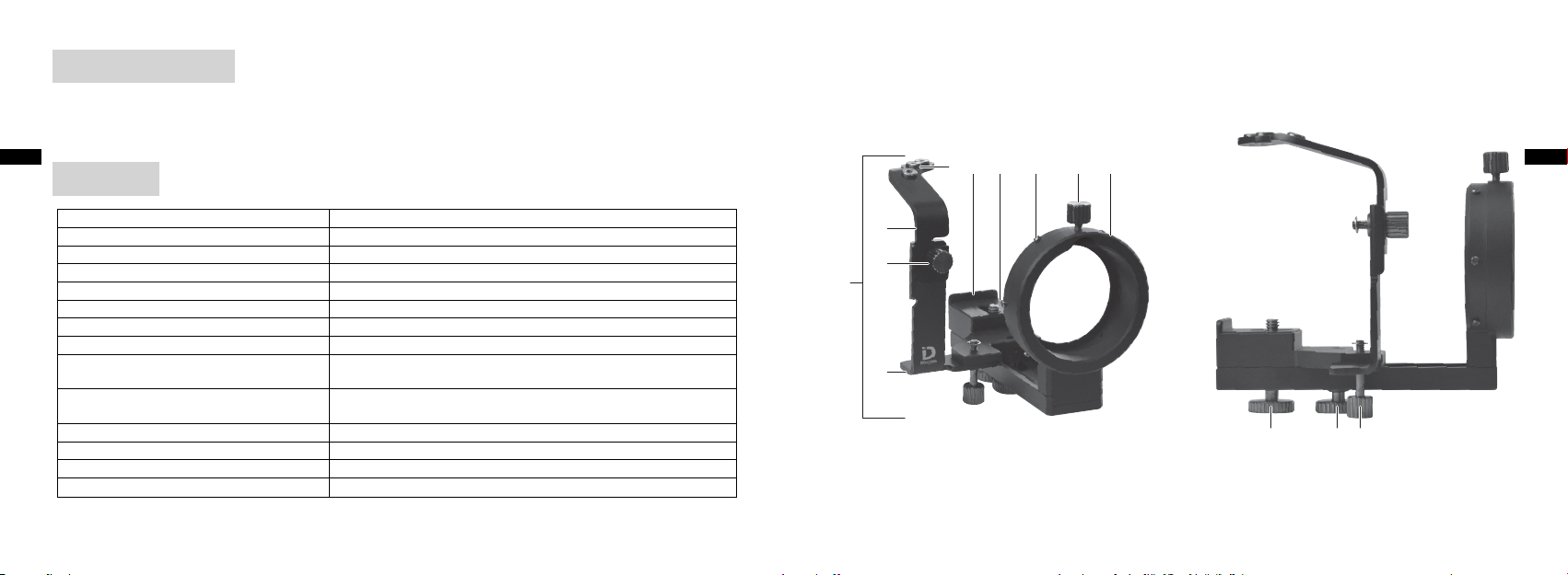
Elemento(i) fornito(i)
acb
Cavo flessibile di scatto × 1
•
Tappo antiscivolo × 2
•
Foglio di schermatura luce in gomma × 1
•
It
Panoramica
56 7 8 9 0
It
Corpo (staffa) Staffa per digiscoping DSB-N1
1
Base scatto otturatore A Consente di regolare la posizione del cavo flessibile di scatto
2
Manopola di fissaggio della base scatto otturatore A
3
Base scatto otturatore B Consente di montare la 2 base scatto otturatore A
4
Presa del cavo flessibile di scatto Consente di collegare il cavo flessibile di scatto (tre fori)
5
Sporgenza della base di montaggio fotocamera
6
Base di montaggio fotocamera Consente di montare la fotocamera sulla 1 staffa
7
Sporgenze di fissaggio del foglio
8
di schermatura luce in gomma
Manopola di fissaggio dell'oculare DS Consente di fissare 0 l'inserto dell'oculare (attacco DS) all'oculare
9
Inserto oculare (attacco DS) La parte che consente di inserire l'attacco DS dell'oculare
0
Vite di fissaggio fotocamera
a
Manopola scorrevole di fissaggio Consente di fissare la posizione della fotocamera all'indietro e in avanti
b
Manopola di fissaggio della base scatto otturatore B
c
Prima dell'uso, assicurarsi di aver capito le funzioni del prodotto.
Nomi delle parti Descrizione
Consente di fissare la 2 base scatto otturatore A e la 4 base scatto otturatore B
Consente di allineare la parte posteriore della fotocamera
Le sporgenze servono a fissare il foglio di schermatura luce in gomma
(sei sporgenze)
(Attacco DS: attacco per il fissaggio del prodotto)
Consente di fissare la fotocamera alla 7 base di montaggio fotocamera
Consente di fissare la 4 base scatto otturatore B alla staffa Digiscoping
84
2
3
1
4
85
Page 44

Modelli applicabili
(a partire da settembre 2012)
Ripresa
Fotocamere applicabili:
Nikon 1 V1, Nikon 1 J1 e Nikon 1 J2
Obiettivi fotocamera applicabili:
It
1 NIKKOR VR 10-30 mm f/3,5-5,6
1 NIKKOR 11-27,5 mm f/3,5-5,6
1 NIKKOR 18,5 mm f/1,8
Fieldscope applicabili:
EDG85 VR/EDG85-A VR/EDG85/EDG85-A/EDG65/EDG65-A/ED82/ED82-A/
EDIII/EDIII-A/III/III-A/ED50/ED50-A
Oculari applicabili:
FEP-20W, FEP-30W, FEP-38W, FEP-50W, FEP-75W e FEP-25LER
16 × wide/24 × wide/30 × wide DS
27 × wide/40 × wide/50 × wide DS
40 × wide/60 × wide/75 × wide DS
* Per informazioni più aggiornate su fotocamere, obiettivi fotocamera, fieldscope e oculari applicabili, consul-
tare il sito Web di Nikon.
86
Esposizione:
Si raccomanda di impostare la [Misuraz. esposimetrica] su [Ponderata centrale]. Se è impostata l'opzione [Matrix] o [Spot],
•
potrebbe essere difficile ottenere un'esposizione ottimale.
Il Sistema Digiscoping presenta proprietà ottiche diverse da quelle degli obiettivi intercambiabili. Il livello di esposizione
•
può pertanto variare in funzione della fotocamera utilizzata. Se necessario, procedere alla compensazione dell'esposizione.
La compensazione dell'esposizione può in particolare essere necessaria in caso di lunghezza focale ridotta in zoommata.
Messa a fuoco:
Al momento della ripresa, regolare la messa a fuoco ruotando la ghiera di messa a fuoco del fieldscope mentre si guarda
•
l'oggetto sul monitor LCD o attraverso il mirino della fotocamera e procedere alle regolazioni di precisione con la funzione
AF (messa a fuoco automatica) della fotocamera.
La messa a fuoco risulterà difficile da regolare nei casi indicati di seguito. Per la Nikon 1, modificare, se necessario, le impo-
•
stazioni del monitor LCD.
- Se l'immagine nel mirino appare scura al momento della ripresa con teleobiettivo
- Se l'oggetto è scuro
Scatto dell'otturatore:
Se si utilizza il cavo flessibile di scatto in dotazione, premere con delicatezza. Non premere con forza, altrimenti la fotocame-
•
ra rischia di inclinarsi.
Per evitare vibrazioni dovute alla ripresa con forte ingrandimento, utilizzare il cavo flessibile di scatto, l'autoscatto o il teleco-
•
mando.
It
87
Page 45

Montaggio
b
Nota) Fare riferimento ai numeri cerchiati della pagina "Panorami-
ca".
It
Nota) Per allentare tutte le manopole e viti occorre ruotarle in
senso antiorario; per serrarle, ruotarle in senso orario.
Preparazione
1. Porre un tappo antiscivolo sul pulsante di scatto della fotocamera
(Fig. 1)
2. Montare il fieldscope sul treppiedi.
3. Allentare la c manopola di fissaggio della base scatto ottura-
tore B e smontare la 4 base scatto otturatore B dalla 1 staffa.
(Fig. 2)
Staffa per digiscoping
1. Montare la 1 staffa all'oculare DS.
Fig. 1
Fig. 2
4
1
c
Allentare la 9 manopola di fissaggio dell'oculare DS ed
inserire sino in fondo 0 l'inserto dell'oculare (attacco DS). Premendo contro l'inserto, fissarlo con la 9 manopola di fissaggio
dell'oculare DS. (Fig. 3)
[Nota]
Assicurarsi che 0 l'inserto dell'oculare (attacco DS) sia fissato
saldamente all'attacco DS. In caso contrario, la fotocamera montata rischia di cadere a causa del suo stesso peso.
2. Allentare la b manopola scorrevole di fissaggio, far scorrere la
base di montaggio fotocamera fino alla posizione indicata
7
nella Fig. 4 ed avvitare temporaneamente la base di montaggio
fotocamera.
9
0
Fig. 3
1
It
Fig. 4
7
88
89
Page 46

Fissaggio della fotocamera
1. Accendere la fotocamera, attivare il pulsante zoom ed estendere
l'obiettivo della fotocamera fino alla posizione di massima estensione. (Fig. 5)
2. Fissare la fotocamera alla 1 staffa.
It
Montare la fotocamera alla 7 base di montaggio fotocamera
ed allineare la parte posteriore della fotocamera alla 6 sporgen-
za della base di montaggio fotocamera.
Avvitare la a vite di fissaggio fotocamera nel foro del treppiedi
e fissare temporaneamente la fotocamera al treppiedi. (Fig. 6)
[Nota]
Se il fieldscope montato è del tipo con configurazione ad angolo,
la fotocamera scivola a causa del suo stesso peso. Maneggiare
pertanto il fieldscope con attenzione, in modo che la parte anteriore dell'obiettivo della fotocamera non venga in contatto con
l'oculare o con 0 l'inserto dell'oculare (attacco DS).
Fig. 5
Fig. 6
6
1
7
a
Regolazione dell'asse ottico
1.
Attivare il pulsante zoom ed impostare lo zoom in posizione di
grandangolo.
2. Guardando sul monitor LCD o attraverso il mirino della fotocamera, procedere alle regolazioni in modo che il cerchio dell'oculare si allinei al centro dell'immagine.
All'accensione della fotocamera, se si vede quanto illustrato nella
Fig. A, il campo visivo del fieldscope è decentrato verso destra (o
verso sinistra) rispetto alla fotocamera. Procedere alle opportune
regolazioni dell'angolo della fotocamera (vedi Fig. F) finché non
si vede quanto illustrato nella Fig. B.
Dopo aver regolato l'asse ottico, allentare la a vite di fissaggio
fotocamera e fissare la fotocamera.
3. Allentare la b manopola scorrevole di fissaggio e spostare
in avanti la fotocamera con la manopola scorrevole di fissaggio,
quindi fissare la fotocamera nella posizione in cui il campo visivo
è nitido ed i quattro angoli di vignettatura sono circa delle stesse
dimensioni che nella Fig. C. La Fig. D dà un esempio di campo
visivo non sufficientemente nitido. In funzione della propria
combinazione, potrebbe non apparire come nella Fig. C.
Se il campo visivo appare come nella Fig. E, la fotocamera è disal-
lineata a sinistra. Allentare la a vite di fissaggio fotocamera,
quindi regolare con precisione la posizione della fotocamera
finché il campo visivo non apparirà come nella Fig. C. (Fig. F)
Fig. A Fig. B
It
Fig. C Fig. D
Fig. E Fig. F
90
91
Page 47

[Nota]
b
7
Per impedire che l'obiettivo venga in contatto con l'oculare, assicurarsi
•
che la parte anteriore dell'obiettivo della fotocamera non si trovi a
meno di circa 3 mm (0,1 pollici) 0 dall'inserto dell'oculare (attacco
DS). (Fig. 8)
It
Se si regola l'asse ottico quando è in uso un fieldscope del tipo con
•
configurazione ad angolo, la fotocamera scivola a causa del suo stesso
peso. Maneggiare pertanto il fieldscope con attenzione, in modo che la
parte anteriore dell'obiettivo della fotocamera non venga in contatto
con l'oculare o con 0 l'inserto dell'oculare (attacco DS).
0
0
3 mm (0,1 pollici)
Fig. 7
a
Fig. 8
Montaggio della base scatto otturatore
Nota) Se non si utilizza il cavo flessibile di scatto, non è necessario
compiere le operazioni seguenti.
Due scanalature sono presenti sulla 2 base scatto otturatore
A. Selezionare la scanalatura alla quale è fissata la 3 manopola
di fissaggio della base scatto otturatore A, in funzione della
fotocamera utilizzata. La scanalatura superiore è destinata al
modello J1/J2; quella inferiore, al modello V1. (Fig. 9)
1. Allentare la 3 manopola di fissaggio della base scatto ottu-
ratore A sulla 4 base scatto otturatore B, selezionare l'altezza
della 2 base scatto otturatore A, quindi serrare la 3 mano-
pola di fissaggio della base scatto otturatore A. (Fig. 10)
2. Allentare la c manopola di fissaggio della base scatto
otturatore B ed inserire la 4 base scatto otturatore B nella
rientranza della parte inferiore della 7 base di montaggio
fotocamera. (Fig. 11)
3. Serrare la c manopola di fissaggio della base scatto ottura-
tore B e fissare la 4 base scatto otturatore B alla staffa.
(Fig. 11) Per estrarre la base scatto otturatore, B allentare la c
manopola di fissaggio della base scatto otturatore B ed
estrarre la 4 base scatto otturatore B.
2
2
3
4
Fig. 10
J1/J2
V1
4
Fig. 9
It
Fig. 11
4
c
92
93
Page 48

Collegamento del cavo flessibile di scatto
Sulla 2 base scatto otturatore A vi sono due fori per viti. Selezionare il foro corretto in cui sarà collegato il cavo flessibile di scatto, in
funzione della fotocamera utilizzata. (Fig. 12)
Il foro per vite a sinistra è previsto per il modello J1/J2, mentre il foro
in mezzo è destinato al modello V1.
It
1. Avvitare l'estremità del cavo flessibile di scatto nell'apposita presa
. (Fig. 13)
5
2. Dopo aver premuto il cavo flessibile di scatto, procedere alle
regolazioni in modo che l'estremità del cavo flessibile di scatto si
trovi nel mezzo del pulsante di scatto della fotocamera.
Allentare la 3 manopola di fissaggio della base scatto ottura-
tore A o la c manopola di fissaggio della base scatto otturatore B, quindi regolare la 2 base scatto otturatore A o la 4
base scatto otturatore B. (Fig. 14)
Fissaggio del foglio di schermatura luce in gomma
Il foglio di schermatura luce in gomma in dotazione viene utilizzato quando è necessario ridurre la luce solare o di altra provenienza che può entrare nella fotocamera.
1. Agganciare i fori del foglio di schermatura luce in gomma alle 8
apposite sporgenze di fissaggio. (Fig. 15)
[Nota]
Al momento di regolare nuovamente la posizione della fotocamera in
avanti o di utilizzare lo zoom dopo il fissaggio del foglio di schermatura luce in gomma, assicurarsi che l'obiettivo della fotocamera non entri
in contatto con l'oculare o con 0 l'inserto dell'oculare (attacco DS).
94
8
2
J1/J2 V1
Fig. 12
8
Fig. 13
5
2
2
Fig. 14
3
Fig. 15
Precauzioni per la ripresa
Per ridurre il movimento della fotocamera durante le riprese, utilizzare un treppiedi solido.
•
Può verificarsi un effetto vignettatura o possono apparire delle ombre in funzione di determinate condizioni, come il
•
modello di fotocamera ed il tipo di oculare da montare, oppure la posizione di montaggio o la posizione dello zoom della
fotocamera.
È possibile che non si riesca ad eliminare perfettamente l'effetto vignettatura o le ombre. Regolare attentamente le posizio-
•
ni in modo da ridurre quanto più possibile l'effetto vignettatura e le ombre.
Se non si riesce a mettere perfettamente a fuoco il soggetto con la funzione AF, bloccare la messa a fuoco automatica e
•
regolare nuovamente la messa a fuoco mediante la ghiera di messa a fuoco del fieldscope guardando sul monitor LCD o
attraverso il mirino della fotocamera.
Poiché le riprese vengono effettuate con un forte ingrandimento, la profondità di campo risulterà ridotta. Prestare sufficien-
•
te attenzione alla messa a fuoco.
Se si osserva la presenza di luce sul monitor LCD o sull'immagine (foto), utilizzare il foglio di schermatura luce in gomma per
•
impedire la penetrazione di luce tra l'attacco e l'obiettivo della fotocamera. Se penetra ancora luce, coprire tutta l'attrezzatura con una schermatura ancora più efficace, ad esempio un drappo nero.
Durante il funzionamento, la fotocamera può posizionarsi fuori allineamento. Prima di far scattare l'otturatore, verificare
•
l'eventuale presenza di effetto vignettatura e di ombre e, se necessario, regolare la fotocamera.
Non utilizzare il flash durante le riprese.
•
Durante la ripresa, impostare la funzione di riduzione delle vibrazioni su NO nel menu Nikon 1.
•
In funzione delle condizioni di ripresa, possono apparire disturbi sotto forma di righe.
•
Per la sostituzione delle batterie o del supporto di registrazione, l'eventuale necessità di rimuovere la fotocamera dipende
•
dal modello di fotocamera utilizzato. Dopo la sostituzione, è tuttavia in ogni caso necessario procedere a nuove regolazioni
della posizione di montaggio.
It
95
Page 49

Conservazione e pulizia
Non lavare il prodotto in acqua fredda o calda.
•
Eliminare con delicatezza lo sporco utilizzando un panno morbido e pulito.
•
Non utilizzare solventi organici, come benzene o diluente, né prodotti per la pulizia che contengano solventi organici.
•
It
Specifiche del prodotto
It
Dimensioni
(ripiegato)
Massa (peso)
* Per il calcolo della lunghezza focale sintetica, fare riferimento alla formula seguente.
Lunghezza focale sintetica = Ingrandimento dell'oculare × Lunghezza focale dell'obiettivo fotocamera (2,7× per
la conversione 35mm (1,4 pollici))
101 (L) × 106 (A) × 127 (P) mm (senza viti)
4,0 (L) × 4,2 (A) × 5,0 (P) pollici (senza viti)
270 g (senza accessori in dotazione)
9,5 once (senza accessori in dotazione)
96
97
Page 50

TACK FÖR ATT DU KÖPT ETT DIGISCOPING BRACKET DSB-N1.
Läs bruksanvisningen noga innan du använder denna produkt, och se till att produkten används på rätt sätt.
•
Förvara bruksanvisningen på lämpligt sätt om den behöver läsas vid ett senare tillfälle.
•
Specifikationer och konstruktion kan komma att ändras utan föregående meddelande.
•
Ingen reproduktion i någon form av denna bruksanvisning, helt eller delvis (förutom korta citat i testartiklar eller recensio-
•
ner) kan göras utan skriftligt tillstånd från NIKON VISION CO., LTD.
Se
SÄKERHET OCH FÖRSIKTIGHET VID ANVÄNDNING
Läs denna bruksanvisning noga och se till att du förstår innehållet i den innan du använder produkten för att
säkerställa att produkten används på ett säkert sätt.
Följande anmärkningar används för att ange graden av skador som kan uppstå vid felaktig användning av den-
■
na produkt.
Denna indikering varnar dig för eventuell felaktig användning som sker till följd av
VARNING
FÖRSIKTIGHET
att innehållet som beskrivs ignoreras, vilket kan resultera i potentiella dödsfall eller
allvarlig skada.
Denna indikering varnar dig för eventuell felaktig användning som sker till följd av
att innehållet som beskrivs ignoreras, vilket kan resultera i skada eller materialförlust.
VARNING
Titta inte i direkt solljus eller i starkt ljus genom Digiscoping Bracket DSB-N1 eller sökaren i kameran monterad med Digisco-
•
ping Bracket DSB-N1.
FÖRSIKTIGHET
Förvara inte produkten på platser som utsätts för direkt solljus under en längre tid.
•
Se till att förpackningen, förpackningsmaterial och medföljande produkt(er) etc. är utom räckhåll för barn.
•
Använd inte denna produkt under promenad.
•
Flytta inte på produkten medan den sitter monterad på kameran eftersom produkten kan falla av.
•
Produkten består av många rörliga delar. Försäkra dig om att du till fullo förstår dess användning och funktioner för samtli-
•
ga justeringsrattar och monteringsrattar innan det används.
•
Denna produkt består av monterade metalldelar. Ägna tillräcklig uppmärksamhet åt hantering av produkten, så att att du
inte klämmer fingrarna eller får en skada. Ha största uppmärksamhet om ett barn använder produkten.
Se
98
99
Page 51

Medföljande produkt(er)
acb
Kabelavtryckare × 1
•
Antiglidplatta × 2
•
Ljusskydd i gummi × 1
•
Se
Översikt
100
Kamerahus (skena) Digiscoping Bracket DSB-N1
1
Avtryckarfäste A Justerar positionen för kabelavtryckaren
2
Monteringsratt för avtryckarfäste A Håller fast 2 avtryckarfäste A på 4 avtryckarfäste B
3
Avtryckarfäste B Håller fast 2 avtryckarfäste A
4
Kabelavtryckarfäste Fäste för kabelavtryckare som ska skruvas fast (tre hål)
5
Styrning i kamerafästet Riktar in den bakre delen av kameran
6
Kamerafäste Håller fast kameran på 1 skenan
7
Fästpunkter för
8
ljusskydd i gummi
Monteringsratt för DS okular Håller fast 0 okularringen (DS-fäste) i okularet
9
Okularring (DS-fäste) En del för att sätta fast DS-fästet i okularet
0
Fastsättningsskruv för kamera Skruvar fast kameran på 7 kamerafästet
a
Ratt för justering av kameran Kameran kan justeras framåt och bakåt
b
Monteringsratt för avtryckarfäste B Håller fast 4 avtryckarfäste B på Digiscoping Bracket
c
Se till att du förstår funktionerna på produkten innan den används.
Nomenklatur Beskrivning
Punkter för att sätta fast ljusskyddet i gummi (sex punkter)
(DS-fäste: Ett fäste att montera på produkten)
56 7 8 9 0
2
3
1
4
Se
101
Page 52

Tillämpliga modeller
(September 2012)
Fotografering
Tillämpliga kameror:
Nikon 1 V1, Nikon 1 J1, och Nikon 1 J2
Tillämpligt kameraobjektiv:
1 NIKKOR VR 10-30 mm f/3,5-5,6
Se
1 NIKKOR 11-27,5 mm f/3,5-5,6
1 NIKKOR 18,5 mm f/1,8
Tillämpliga tubkikare:
EDG85 VR/EDG85-A VR/EDG85/EDG85-A/EDG65/EDG65-A/ED82/ED82-A/
EDIII/EDIII-A/III/III-A/ED50/ED50-A
Tillämpliga okular:
FEP-20W, FEP-30W, FEP-38W, FEP-50W, FEP-75W, och FEP-25LER
16 × wide/24 × wide/30 × wide DS
27 × wide/40 × wide/50 × wide DS
40 × wide/60 × wide/75 × wide DS
* Se Nikons webbplats för information om senaste tillämpliga kameror, objektiv, tubkikare och okular.
102
Exponering:
Det rekommenderas att ställa in [Ljusmätning] på [Centrumvägd]. Optimal exponering kanske inte erhålls om [Matris] eller
•
[Spot] är valt.
Digiscoping-systemet skiljer i optiska egenskaper från utbytbara objektiv. Därför kan exponeringsnivån variera med varje
•
kamera. Gör en exponeringskompensation vid behov. En kort brännvidd för speciellt inzoomning kan kräva kompensering
av exponeringen.
Fokus:
Gör fokusjusteringar när du fotar genom att vrida på fokusringen på tubkikaren och samtidigt titta på motivet på LCD-
•
skärmen eller i sökaren i kameran, samt göra finjusteringar med AF (autofokus) på kameran.
Det kan vara svårt att justera fokus i följande fall. Gör ändringar i LCD-skärmen för Nikon 1 vid behov.
•
- Om bilden i sökaren är mörk vid tidpunkten för telefotografering
- Om föremålet är mörkt
Avtryckare:
Tryck försiktigt på kabelavtryckaren, om den används. Tryck inte för kraftigt på avtryckaren eftersom det inställda motivet i
•
kameran kan förflyttas i bilden.
Använd en kabelavtryckare, självutlösare eller fjärrkontroll för att förhindra vibrationer vid fotografering med hög försto-
•
ring.
Se
103
Page 53

Fastsättning
b
Obs) Se de inringade siffrorna på sidan "Översikt".
Obs) Alla rattar och skruvar lossas när de vrids moturs och dras
åt när de vrids medurs.
Se
Förberedelse
1. Fäst en antiglidplatta på kamerans avtryckare. (Fig. 1)
2. Montera tubkikaren på ett stativ.
3. Lossa c monteringsratt för avtryckarfäste B och lossa 4
avtryckarfäste B från 1 skenan. (Fig. 2)
Digiscoping-skena
1. Montera 1 skenan på DS okular.
Fig. 1
Fig. 2
4
1
c
Lossa 9 monteringsratt för DS okular och för in 0 okularrin-
gen (DS-fäste) hela vägen tills det tar stopp. Håll det intryckt och
skruva fast det med 9 monteringsratten för DS okular. (Fig. 3)
[O bs]
Se till att 0 okularringen (DS-fäste) sitter säkert fast i DS-fästet.
Om det inte sitter fast säkert kan kameran falla ur på grund av sin
egenvikt.
2. Lossa b ratten för justering av kameran, skjut 7 kamerafä-
stet till den position som visas i Fig. 4, och skruva tillfälligt fast
kamerafästet.
9
0
Fig. 3
1
Se
Fig. 4
7
104
105
Page 54

Sätta fast kameran
1. Sätt på kameran, och använd zoomknappen för att föra ut objektivet så långt som möjligt. (Fig. 5)
2. Sätt fast kameran på 1 skenan.
Montera kameran på 7 kamerafästet och rikta in den bakre
Se
delen av kameran mot 6 styrningen i kamerafästet.
Skruva fast a fastsättningsskruven för kameran i hålet i stati-
vet och sätt tillfälligt på kameran på stativet. (Fig. 6)
[Obs]
Kameran kan röra sig på grund av sin egenvikt om tubkikare med
vinklat hus har monterats. Hantera därför tubkikaren försiktigt så
att den främre kameralinsen inte kommer i kontakt med okularet
eller 0 okularringen (DS-fäste).
Fig. 5
Fig. 6
6
1
7
a
Justera den optiska axeln
1.
Använd zoomknappen och ställ in zoomen på kort brännvidd.
2. Titta på LCD-skärmen eller i sökaren på kameran och gör justeringar så att cirkeln i okularet riktas in mot bildens mitt.
När kameran sätts på och bilden ser ut som Fig. A är siktfältet
i tubkikaren felriktat åt höger (eller vänster) i förhållande till
kameran. Gör finjusteringar på kameravinkeln (se Fig. F) så att
det ser ut som Fig. B.
När den optiska axeln är justerad, lossa a fastsättningsskru-
ven för kameran och fäst kameran.
3. Lossa b ratten för justering av kameran och flytta kameran
tillsammans med ratten för justering av kameran framåt, och
skruva fast kameran där synfältet är tydligt och de fyra vinjetteringshörnen har samma storlek som Fig. C. Fig. D är ett exempel
på när synfältet inte är tillräckligt tydligt. Beroende på din kombination kanske det inte visas som i Fig. C.
Om det ser ut som i Fig. E är kameran felriktad åt vänster. Lossa
fastsättningsskruven för kameran, och gör finjusteringar
a
av kamerans läge så att det ser ut som i Fig. C. (Fig. F)
Fig. A Fig. B
Se
Fig. C Fig. D
Fig. E Fig. F
106
107
Page 55

[Obs]
b
7
För att förhindra att kameralinsen kommer i kontakt med okularet bör
•
kameralinsens främre yta inte vara närmare än 3 mm (0,1 in) från 0
okularringen (DS-fäste). (Fig. 8)
Kameran kan röra sig på grund av sin egenvikt om den optiska axeln
•
justeras medan tubkikaren med vinklat hus används. Hantera därför
tubkikaren försiktigt så att den främre kameralinsen inte kommer i
Se
kontakt med okularet eller 0 okularringen (DS-fäste).
0
0
3 mm (0,1 in)
Fig. 7
a
Fig. 8
Montering av avtryckarfäste
Obs) Följande steg är inte nödvändiga om kabelavtryckare inte
används.
Det finns två spår på 2 avtryckarfäste A. Välj rätt spår där 3
monteringsratt för avtryckarfäste A sitter, beroende på kamera som används. Spåret på den övre sidan är till för J1/J2 och
den för den undre sidan är till för V1. (Fig. 9)
1. Lossa 3 monteringsratt för avtryckarfäste A på 4
avtryckarfäste B, välj höjd på 2 avtryckare A, och dra fast 3
monteringsratt för avtryckarfäste A. (Fig. 10)
2. Lossa c monteringsratt för avtryckarfäste B och för in 4
avtryckarfäste B i urtaget i botten på 7 kamerafästet. (Fig.
11)
3. Dra fast c monteringsratt för avtryckarfäste B och fäst 4
avtryckarfäste B på skenan. (Fig. 11) För att lossa avtryckarfäste B, lossa c monteringsratt för avtryckarfäste B och dra ut
avtryckarfäste B.
4
2
2
3
4
Fig. 10
J1/J2
V1
4
Fig. 9
Se
Fig. 11
4
c
108
109
Page 56

Montering av kabelavtryckare
Det finns två skruvhål på 2 avtryckarfäste A. Välj rätt skruvhål där
kabelavtryckaren ska sitta beroende på vilken kamera som används.
(Fig. 12)
Skruvhålet på vänster sida är till för J1/J2 och det i mitten är till för V1.
1. Skruva in änden på kabelavtryckaren i 5 kabelavtryckarfästet.
Se
(Fig. 13)
2. Tryck på kabelavtryckaren och gör justeringar så att änden på kabelavtryckaren är placerad i mitten på kamerans avtryckarknapp.
Lossa 3 monteringsratt för avtryckarfäste A eller c mon-
teringsratt för avtryckarfäste B, och gör finjusteringar på 2
avtryckarfäste A eller 4 avtryckarfäste B. (Fig. 14)
Montering av ljusskydd i gummi
Det medföljande ljusskyddet i gummi används för att minska mängden solljus eller annat ljus som kommer in i kameran.
1. Haka fast hålen i ljusskyddet i gummi på 8 fästpunkterna för
ljusskydd i gummi. (Fig. 15)
[Obs]
Se till att kamerans lins inte kommer i kontakt med okularet eller
okularringen (DS-fäste) när kamerans position justeras i
0
framåtriktningen eller om zoomning görs efter det att ljusskyddet
i gummi är fastsatt.
8
2
J1/J2 V1
Fig. 12
8
Fig. 13
5
2
2
Fig. 14
3
Fig. 15
Att tänka på vid fotografering
Använd ett stadigt stativ för att minimera skakningar när bilder tas.
•
Vinjettering eller skuggor kan uppstå beroende på olika förhållanden, såsom kameramodell och vilken typ av okular som
•
sitter monterad eller monteringsläget eller kamerans inzoomningsläge.
Vinjettering eller skuggor kan inte uteslutas helt. Gör optimala inställningar noga för att minimera vinjettering eller skuggor.
•
Om det inte går att fokusera på ett föremål med AF-funktionen, lås AF och ställ in fokus igen med hjälp av fokusringen på
•
tubkikaren samtidigt som motivet betraktas på LCD-skärmen eller i sökaren i kameran.
Ett grunt skärpedjup kommer att resultera på grund av fotografering med hög förstoring. Var noga med fokuseringen.
•
Om du märker att det tränger in ljus på LCD-skärmen eller bilden, kan ljusskyddet i gummi användas för att hindra att
•
ljus kommer in mellan fästet och kamerans lins. Om det fortfarande tränger in ljus kan hela utrustningen täckas över med
exempelvis en svart duk.
Kamerans position kan flytta sig efter en fotografering. Kontrollera innan nästa bild tas att vinjettering och skuggor finns
•
och justera kameran vid behov.
Använd inte blixt vid fotograferingen.
•
När du tar bilder ska du sätta vibrationsreduceringsfunktionen till läge AV på menyn för Nikon 1.
•
Brus i form av linjer kan visas på bilder beroende på förhållandet vid fotograferingen.
•
Vid byte av kamera eller inspelningsmedia i kameran behöver den, beroende på modell, kanske inte lossas från utrustnin-
•
gen. I vilket fall som helst är nya inställningar nödvändiga efter ett sådant arbete.
Se
110
111
Page 57

Förvaring och rengöring
Tvätta inte av produkten med kallt eller varmt vatten.
•
Torka försiktigt av smuts från produkten med en mjuk och ren trasa.
•
Använd inte organiska lösningsmedel, såsom bensin eller thinner, eller rengöringsmedel som innehåller några organiska
•
lösningsmedel.
Se
Produktspecifikationer
Se
Mått (hopfälld)
Vikt
* Se följande uttryck för beräkning av syntetisk brännvidd.
Syntetisk brännvidd = Förstoring i okularet × Brännvidd på objektivet (2,7× i händelse av 35 mm [1,4 in] konvertering)
101 (B) × 106 (H) × 127 (D) mm (utan skruvar)
4,0 (B) × 4,2 (H) × 5,0 (D) in (utan skruvar)
270 g (utan medföljande produkt[er])
9,5 oz (utan medföljande produkt[er])
112
113
Page 58

HARTELIJK DANK VOOR HET AANSCHAFFEN VAN DE DIGISCOPINGBEUGEL DSB-N1.
Lees deze handleiding zorgvuldig door voordat u het product gaat gebruiken en zorg ervoor dat u het product op correcte
•
wijze gebruikt.
Bewaar deze handleiding na het lezen zodat u deze later opnieuw kunt raadplegen.
•
Specificaties en ontwerp kunnen zonder kennisgeving worden gewijzigd.
•
Gehele of gedeeltelijke vermenigvuldiging van deze handleiding in welk vorm dan ook (behalve voor korte citaten in
•
beoordelingsartikelen of recensies) is niet toegestaan zonder schriftelijke toestemming van NIKON VISION CO., LTD.
Nl
VEILIGHEIDS- EN BEDIENINGSVOORSCHRIFTEN
Voor een veilig gebruik van dit product leest u deze handleiding zorgvuldig door en zorgt u ervoor dat u de
verstrekte informatie begrijpt voordat u het product gaat bedienen.
De volgende aanduidingen worden gebruikt om de mate van letsel of schade aan te geven die zou kunnen
■
ontstaan ten gevolge van onjuist gebruik van dit product.
Deze aanduiding attendeert u op het feit dat enig onjuist gebruik dat voor-
WAARSCHUWING
tvloeit uit het negeren van de hier beschreven inhoud kan resulteren in
overlijden of ernstig letsel.
Deze aanduiding attendeert u op het feit dat enig onjuist gebruik dat voor-
LET OP
tvloeit uit het negeren van de hier beschreven inhoud kan resulteren in letsel
of materiële schade.
WAARSCHUWING
Kijk niet rechtstreeks in de zon of naar intens licht door de Digiscopingbeugel DSB-N1 of het objectief van de camera waa-
•
rop de Digiscopingbeugel DSB-N1 is gemonteerd.
LET OP
Bewaar het product niet voor lange tijd op plaatsen die zijn blootgesteld aan direct zonlicht.
•
Houd de verpakkingsdoos, verpakkingsmaterialen en meegeleverde items, enz. buiten het bereik van kinderen.
•
Gebruik dit product niet terwijl u loopt.
•
Verplaats het product dat aan de camera is gemonteerd niet anders kan het product losraken.
•
Het product bevat een groot aantal beweegbare onderdelen. Zorg ervoor dat u de rol en functie van alle afstellings- en
•
bevestigingsknoppen volledig begrijpt voordat u het product gaat gebruiken.
•
Het product bestaat uit geassembleerde metalen onderdelen. Let goed op bij het hanteren van het product zodat u niet
met uw vingers klem komt te zitten of ander letsel oploopt. Let heel goed op als een kind het product gebruikt.
Nl
114
115
Page 59

Meegeleverd(e) item(s)
acb
•
Kabelontspanner × 1
•
Slipvrij kussentje × 2
•
Lichtafschermende rubberen kap × 1
Overzicht
Nl
Body (beugel) Digiscopingbeugel DSB-N1
1
Sluiterontspannerbasis A Past de positie van de kabelontspanner aan
2
Bevestigingsknop voor sluiterontspannerbasis A
3
Sluiterontspannerbasis B Voor montage van 2 sluiterontspannerbasis A
4
Fitting voor kabelontspanner Fitting voor het inschroeven van de kabelontspanner (drie gaten)
5
Uitsteeksel op camera-aansluitvoet Voor uitlijning van het achterste gedeelte van de camera
6
Camera-aansluitvoet Voor montage van de camera op de 1 beugel
7
Bevestigingsuitsteeksels voor licht-
8
afschermende rubberen kap
Bevestigingsknop voor DS-oogglas
9
Inzetstuk voor oogglas (DS-beugel) Een onderdeel voor het plaatsen van de DS-beugel van het oogglas
0
Camerabevestigingsschroef Voor bevestiging van de camera op de 7 camera-aansluitvoet
a
Verschuifbare bevestigingsknop Voor het vooruit of achteruit instellen van de camerapositie
b
Bevestigingsknop voor sluiterontspannerbasis B
c
Zorg ervoor dat u de functies van het product begrijpt voordat u het gaat gebruiken.
116
Terminologie Beschrijving
Voor bevestiging van 2 sluiterontspannerbasis A en 4 sluiterontspannerbasis B
Uitsteeksels voor bevestiging van de rubberen afschermingskap (zes
uitsteeksels)
Voor bevestiging van 0 inzetstuk voor oogglas (DS-beugel) aan het oogglas
(DS-beugel: een beugel voor het bevestigen van het product)
Voor bevestiging van 4 sluiterontspannerbasis B aan de Digiscopingbeugel
56 7 8 9 0
Nl
2
3
1
4
117
Page 60

Geschikte modellen
(vanaf september 2012)
Opname
Geschikte camera's:
Nikon 1 V1, Nikon 1 J1 en Nikon 1 J2
Geschikt cameraobjectief:
1 NIKKOR VR 10-30 mm f/3,5-5,6
1 NIKKOR 11-27,5 mm f/3,5-5,6
Nl
1 NIKKOR 18,5 mm f/1,8
Geschikte telescopen:
EDG85 VR/EDG85-A VR/EDG85/EDG85-A/EDG65/EDG65-A/ED82/ED82-A/
EDIII/EDIII-A/III/III-A/ED50/ED50-A
Geschikte oogglazen:
FEP-20W, FEP-30W, FEP-38W, FEP-50W, FEP-75W en FEP-25LER
16 × groothoek/24 × groothoek/30 × groothoek DS
27 × groothoek/40 × groothoek/50 × groothoek DS
40 × groothoek/60 × groothoek/75 × groothoek DS
* Voor de meest recente informatie over de geschikte camera's, cameraobjectieven, telescopen en oogglazen
raadpleegt u de website van Nikon.
118
Belichting:
Het wordt aanbevolen [Lichtmeting] in te stellen op [Centrumgericht]. Mogelijk wordt geen optimale belichting verkregen
•
als [Matrixmeting] of [Spot] is ingesteld.
Het Digiscoping-systeem verschilt qua optische eigenschappen van verwisselbare objectieven. Daarom kan het belichting-
•
sniveau bij elke camera verschillen. Voer zo nodig belichtingscorrectie uit. Met name bij een korte brandpuntsafstand voor
zoomen is mogelijk belichtingscorrectie vereist.
Scherpstelling:
Pas tijdens het opnemen de scherpstelling aan door aan de scherpstelring van de telescoop te draaien terwijl u het onde-
•
rwerp op het LCD-scherm of in de zoeker van de camera bekijkt en voer fijnafstellingen uit met de AF-functie (autofocus)
van de camera.
Het aanpassen van de scherpstelling is moeilijk in de volgende gevallen. Voer zo nodig wijzigingen in de LCD-instelling voor
•
de Nikon 1 uit.
- Als het beeld in de zoeker donker is bij het maken van telefoto-opnamen
- Als het onderwerp donker is
Het ontspannen van de sluiter:
Druk zachtjes op de meegeleverde kabelontspanner, als u deze gebruikt. Druk de sluiterontspanner niet te krachtig in om
•
te voorkomen dat de ingestelde positie van de camera verandert.
Gebruik een kabelontspanner, zelfontspanner of afstandsbediening om trillen bij opnamen met sterke vergroting te
•
voorkomen.
Nl
119
Page 61

Bevestiging
b
Opmerking: Raadpleeg de omcirkelde nummers op de pagina
"Overzicht".
Opmerking: Alle knoppen en schroeven worden linksom losge-
draaid en rechtsom vastgedraaid.
Nl
Voorbereiding
1. Bevestig een slipvrij kussentje op de sluiterontspanknop van de
camera. (Afb. 1)
2. Monteer de telescoop op het statief.
3. Draai de c bevestigingsknop voor sluiterontspannerbasis B
los en verwijder 4 sluiterontspannerbasis B van de 1 beugel.
(Afb. 2)
Digiscopingbeugel
1. Monteer de 1 beugel aan de DS-oogglazen.
Afb. 1
Afb. 2
4
1
c
Draai de 9 bevestigingsknop voor DS-oogglas los en schuif
het 0 inzetstuk voor oogglas (DS-beugel) helemaal naar
binnen. Bevestig, terwijl u tegen het inzetstuk drukt, het inzetstuk
aan de 9 bevestigingsknop voor DS-oogglas. (Afb. 3)
[Opmerking]
Zorg ervoor dat het 0 inzetstuk voor oogglas (DS-beugel)
stevig aan de DS-beugel is bevestigd. Als dit niet het geval is, kan
de gemonteerde camera naar beneden vallen vanwege het eigen
gewicht.
2. Draai de b verschuifbare bevestigingsknop los, schuif de 7
camera-aansluitvoet naar de positie die wordt weergegeven in
Afb. 4 en schroef de camera-aansluitvoet tijdelijk omlaag.
9
0
Afb. 3
1
Nl
Afb. 4
7
120
121
Page 62

De camera bevestigen
1. Schakel de camera in, bedien de zoomknop en schuif het cameraobjectief naar de uiterste uitgeschoven positie. (Afb. 5)
2. Bevestig de camera aan de 1 beugel.
Monteer de camera op de 7 camera-aansluitvoet en lijn het
achterste gedeelte van de camera uit met het 6 uitsteeksel op
Nl
de camera-aansluitvoet.
Schroef de a camerabevestigingsschroef in het statiefgat en
bevestig de camera tijdelijk op het statief. (Afb. 6)
[Opmerking]
De camera verschuift onder het eigen gewicht als de telescoop
met gehoekte body is gemonteerd. Ga daarom voorzichtig om
met de telescoop zodat de voorzijde van het cameraobjectief
niet in contact komt met het oogglas of het 0 inzetstuk voor
oogglas (DS-beugel).
Afb. 5
Afb. 6
6
1
7
a
De optische as aanpassen
1.
Bedien de zoomknop en stel de zoom in op de groothoekinstelling.
2. Voer, terwijl u op het LCD-scherm of door de zoeker van de
camera kijkt, aanpassingen door zodat de cirkel van het oogglas
zich in het midden van het beeld bevindt.
Als u bij het inschakelen van de camera iets ziet dat lijkt op Afb. A,
dan is het zichtveld van de telescoop niet uitgelijnd aan de rechterkant (of linkerkant) ten opzichte van de camera. Pas de camerahoek
aan (zie Afb. F) totdat deze eruitziet als in Afb. B.
Draai, nadat u de optische as hebt aangepast, de a camerabe-
vestigingsschroef los en bevestig de camera.
3. Draai de b verschuifbare bevestigingsknop los en verplaats
de camera samen met de verschuifbare bevestigingsknop naar
voren. Bevestig vervolgens de camera op de plek waar het
zichtveld scherp is en de vier hoeken met vignettering ongeveer
even groot zijn als in Afb. C. Afb. D is een voorbeeld van een
zichtveld dat niet scherp genoeg is. Afhankelijk van uw combinatie ziet het beeld er wellicht anders uit als in Afb. C.
Als het beeld eruitziet zoals in Afb. E, is de camera niet goed
uitgelijnd aan de linkerkant. Draai de a camerabevestigin-
gsschroef los en voer fijnafstellingen van de camerapositie uit
totdat het beeld eruitziet zoals in Afb. C. (Afb. F)
Afb. A Afb. B
Afb. C Afb. D
Afb. E Afb. F
Nl
122
123
Page 63

[Opmerking]
b
7
Voorkom dat het cameraobjectief in contact komt met het oogglas
•
door ervoor te zorgen dat de voorzijde van het cameraobjectief zich
niet dichter dan ongeveer 3 mm (0,1 inch) van het 0 inzetstuk voor
oogglas (DS-beugel) bevindt. (Afb. 8)
De camera verschuift onder het eigen gewicht als de optische as wordt
•
aangepast als de telescoop met gehoekte body wordt gebruikt. Ga
daarom voorzichtig om met de telescoop zodat de voorzijde van het ca-
Nl
meraobjectief niet in contact komt met het oogglas of het 0 inzetstuk
voor oogglas (DS-beugel).
0
0
3 mm (0,1 inch)
Afb. 7
a
Afb. 8
De sluiterontspannerbasis bevestigen
Opmerking: De volgende stappen zijn overbodig als geen gebruik
wordt gemaakt van de kabelontspanner.
Er bevinden zich twee groeven in 2 sluiterontspannerbasis A.
Selecteer de juiste groef waarbij 3 de bevestigingsknop voor
sluiterontspannerbasis A wordt bevestigd op basis van de
camera die wordt gebruikt. De groef aan de bovenkant is voor
de J1/J2 en de groef aan de onderkant is voor de V1. (Afb. 9)
1. Draai de 3 bevestigingsknop voor sluiterontspannerbasis
A los op 4 sluiterontspannerbasis B, selecteer de hoogte
van 2 sluiterontspanner A en draai de 3 bevestigingsknop
voor sluiterontspannerbasis A vast. (Afb. 10)
2. Draai de c bevestigingsknop voor sluiterontspannerbasis
B los en plaats 4 sluiterontspannerbasis B in de uitsparing
onder in de 7 camera-aansluitvoet. (Afb. 11)
3. Draai de c bevestigingsknop voor sluiterontspannerbasis
B vast en bevestig 4 sluiterontspannerbasis B aan de beugel.
(Afb. 11) U kunt de sluiterontspannerbasis B verwijderen door
de c bevestigingsknop voor sluiterontspannerbasis B
los te draaien en 4 sluiterontspannerbasis B naar buiten te
trekken.
2
2
3
4
Afb. 10
4
Afb. 9
J1/J2
V1
Nl
Afb. 11
4
c
124
125
Page 64
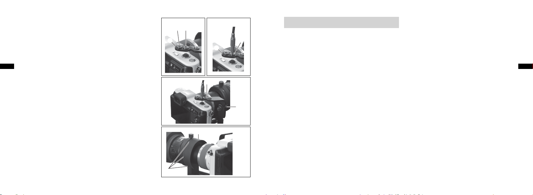
De kabelontspanner bevestigen
Er bevinden zich twee schroefgaten in 2 sluiterontspannerbasis A.
Selecteer het juiste schroefgat voor bevestiging van de kabelontspanner op basis van de gebruikte camera. (Afb. 12)
Het schroefgat aan de linkerkant is bedoeld voor de J1/J2 en het
schroefgat in het midden voor de V1.
1. Schroef het uiteinde van de kabelontspanner in de 5 fitting
Nl
voor kabelontspanner. (Afb. 13)
2. Voer, nadat u op de kabelontspanner hebt gedrukt, aanpassingen door zodat het uiteinde van de kabelontspanner zich in het
midden van de sluiterontspanknop van de camera bevindt.
Draai de 3 bevestigingsknop voor sluiterontspannerbasis A of c beve-
stigingsknop voor sluiterontspannerbasis B los en voer fijnafstellingen door
voor 2 sluiterontspannerbasis A of 4 sluiterontspannerbasis B. (Afb. 14)
De lichtafschermende rubberen kap bevestigen
De meegeleverde lichtafschermende rubberen kap kan worden gebruikt om
ervoor te zorgen dat er minder zonlicht of ander licht de camera binnendringt.
1. Haak de openingen in de lichtafschermende rubberen kap aan de
bevestigingsuitsteeksels voor de lichtafschermende rubbe-
8
ren kap. (Afb. 15)
[Opmerking]
Zorg ervoor dat het cameraobjectief niet in contact komt met het oogglas of het 0 inzetstuk voor oogglas (DS-beugel) bij aanpassing
van de camerapositie in voorwaartse richting of bij bediening van de
zoom nadat de lichtafschermende rubberen kap is aangebracht.
126
8
2
J1/J2 V1
Afb. 12
8
Afb. 13
5
2
2
Afb. 14
3
Afb. 15
Voorzorgsmaatregelen bij het opnemen
Gebruik een stevig statief om trillingen bij het maken van foto's tot een minimum te beperken.
•
Er kan sprake zijn van vignettering of schaduwvorming ten gevolge van relevante omstandigheden, zoals het cameramodel
•
en het type oogglas dat is aangesloten of de bevestigingspositie of zoomafstand van de camera.
Vignettering of schaduwvorming kan niet volledig worden uitgesloten. Optimaliseer de positie-instellingen om vignette-
•
ring en schaduwvorming tot een minimum te beperken.
Als u niet kunt scherpstellen op het onderwerp met behulp van de AF-functie, vergrendelt u de AF en stelt u de focus
•
opnieuw in met de scherpstelring van de telescoop terwijl u op het LCD-scherm of door de zoeker van de camera kijkt.
Een geringe scherptediepte ontstaat bij opnamen met sterke vergroting. Besteed voldoende aandacht aan de scherpstel-
•
ling.
Als u extern licht ziet op het LCD-scherm of het beeld (foto), gebruikt u de meegeleverde lichtafschermende rubberen kap
•
om te voorkomen dat licht binnendringt tussen de beugel en het objectief van de camera. Als er nog steeds licht binnendringt, dekt u het hele apparaat af met een scherm. Hiervoor kunt u een zwarte doek gebruiken.
De camerapositie kan mogelijk verschuiven tijdens de bediening van de camera. Controleer op vignettering en schadu-
•
wvorming voordat u de sluiter ontspant en pas de camera zo nodig aan.
Maak geen gebruik van de flitser tijdens het maken van opnamen.
•
Schakel de vibratiereductiefunctie UIT in het menu Nikon 1 wanneer u opnamen maakt.
•
Afhankelijk van de opnameomstandigheden kan er ruis in de vorm van strepen ontstaan in foto's.
•
Bij het vervangen van de batterijen of opnamemedia moet de camera al dan niet van de aangesloten apparatuur worden
•
losgekoppeld, afhankelijk van de camera. In elk geval moet de montagepositie opnieuw worden afgesteld.
Nl
127
Page 65

Opslag en reiniging
Spoel het product niet af met koud of warm water.
•
Veeg voorzichtig eventueel vuil van het product met behulp van een zachte, schone doek.
•
Gebruik geen organische oplosmiddelen, zoals wasbenzine of verfverdunner, of een reinigingsoplossing die organische
•
oplosmiddelen bevat.
Nl
Productspecificaties
Afmetingen
(in opgevouwen
toestand)
Massa (gewicht)
* Raadpleeg de volgende uitdrukking voor berekening van de effectieve brandpuntsafstand.
Effectieve brandpuntsafstand = Vergroting van oogglas × Brandpuntsafstand van opnameobjectief (2,7 × in
het geval van conversie naar 35 mm (1,4 inch))
101 (B) × 106 (H) × 127 (D) mm (zonder schroeven)
4,0 (B) × 4,2 (H) × 5,0 (D) inch (zonder schroeven)
270 g (zonder meegeleverde items)
9,5 oz (zonder meegeleverde items)
128
Nl
129
Page 66

БЛАГОДАРИМ ВАС ЗА ПОКУПКУ ДЕРЖАТЕЛЯ ДЛЯ УДАЛЕННОГО НАБЛЮДЕНИЯ И ФОТОСЪЕМКИ DSB-N1.
Прежде чем приступать к эксплуатации изделия, внимательно прочитайте эту инструкцию по эксплуатации.
•
Правильно используйте изделие.
После прочтения держите инструкцию в доступном месте для быстрого получения справок.
•
Технические характеристики и конструкция могут быть изменены без предварительного уведомления.
•
Воспроизведение настоящей инструкции, полное или частичное (кроме краткого цитирования в критических
•
статьях или обзорах), запрещается без письменного разрешения компании NIKON VISION CO., LTD.
Ru
БЕЗОПАСНОСТЬ И МЕРЫ ПРЕДОСТОРОЖНОСТИ ПРИ ЭКСПЛУАТАЦИИ
Прежде чем приступать к эксплуатации изделия, внимательно прочитайте настоящую инструкцию и убедитесь в том,
что изложенная в ней информация понимается правильно. Это необходимо для безопасного использования изделия.
Следующие обозначения используются для указания степени травм или повреждений, которые могут
■
быть вызваны неправильным использованием данного изделия.
Это обозначение указывает на то, что неправильное использование изделия
ПРЕДУПРЕЖДЕНИЕ
вследствие несоблюдения положений, изложенных в настоящей инструкции,
может привести к смерти или серьезной травме.
Эта обозначение предупреждает о том, что неправильное использование
ОСТОРОЖНО
изделия вследствие несоблюдения положений, изложенных в настоящей
инструкции, может привести к травме или к материальному ущербу.
ПРЕДУПРЕЖДЕНИЕ
Не смотрите на прямой солнечный свет или на сильный свет через держатель для удаленного наблюдения и
•
фотосъемки DSB-N1 или через объектив фотокамеры, установленный с держателем DSB-N1.
ОСТОРОЖНО
Не храните изделие в местах , подверженных воздействию прямого солнечного света, в течение до лгого времени.
•
Следите за тем, чтобы упаковочная коробка, упаковочные материалы, поставляемые элементы и т.д. хранились в
•
недоступном для детей месте.
Не используете это изделие на ходу.
•
Не переносите изделие установленным на фотокамере, так как оно может отсоединиться и упасть.
•
Изделие состоит из многих подвижных деталей. Прежде чем приступать к эксплуатации изделия, убедитесь в
•
правильном понимании функций всех регулировочных и фиксирующих ручек.
Изделие собрано из металлических деталей. Будьте внимательны при обращении с изделием и старайтесь не
•
прищемить пальцы и не получить травму. Будьте особенно внимательны, если изделие используется ребенком.
Ru
130
131
Page 67

Поставляемые элементы
acb
Спусковой тросик × 1
•
Противоскользящая панель × 2
•
Экранирующий резиновый лист × 1
•
Обзор
Ru
132
Корпус (держатель) Держатель для удаленного наблюдения и фотосъемки DSB-N1
1
Основание спуска затвора A Позволяет регулировать положение спускового тросика
2
Крепежная ручка для основания спуска затвора A Позволяет зафиксировать 2 основание спуска затвора A и 4 основание спуска B
3
Основание спуска затвора B Позволяет установить 2 основание спуска затвора A
4
Гнездо спускового тросика Гнездо для ввинчиваемого спускового тросика (три отверстия)
5
Выступ на основании крепления фотокамеры
6
Основание крепления фотокамеры Позволяет установить фотокамеру на 1 держатель
7
Крепежные выступы для
8
экранирующего резинового листа
Крепежная ручка для окуляра DS
9
Штырек окуляра (крепление DS) Деталь для вставки крепления DS окуляра
0
Фиксирующий винт фотокамеры Позволяет зафиксировать фотокамеру 7 на основании крепления
a
Фиксирующая ручка сдвига
b
Крепежная ручка для основания спуска
c
затвора B
Прежде чем приступать к эксплуатации изделия, убедитесь в правильном понимании всех функций.
Наименования Описание
Позволяет совместить заднюю часть фотокамеры
Выступы для крепления экранирующего резинового листа (шесть
выступов)
Позволяет зафиксировать штырек 0 окуляра (крепление DS) на окуляре
(Крепление DS: крепление для установки изделия)
Позволяет зафиксировать фотокамеру в переднем или заднем положении
Позволяет зафиксировать 4 основание спуска затвора B на держателе
для удаленного наблюдения и фотосъемки
56 7 8 9 0
2
3
1
4
Ru
133
Page 68

Совместимые модели
(на сентябрь 2012 г.)
Съемка
Совместимые фотокамеры:
Nikon 1 V1, Nikon 1 J1 и Nikon 1 J2
Совместимые объективы фотокамеры:
1 NIKKOR VR 10-30 мм f/3,5-5,6
1 NIKKOR 11-27,5 мм f/3,5-5,6
1 NIKKOR 18,5 мм f/1,8
Ru
Совместимые зрительные трубы:
EDG85 VR/EDG85-A VR/EDG85/EDG85-A/EDG65/EDG65-A/ED82/ED82-A/
EDIII/EDIII-A/III/III-A/ED50/ED50-A
Совместимые окуляры:
FEP-20W, FEP-30W, FEP-38W, FEP-50W, FEP-75W и FEP-25LER
16 × широкий/24 × широкий/30 × широкий DS
27 × широкий/40 × широкий/50 × широкий DS
40 × широкий/60 × широкий/75 × широкий DS
* Для получения последней информации о совместимых фотокамерах, объективах, зрительных трубах
и окулярах посетите веб-сайт компании Nikon.
134
Экспозиция:
Для настройки [Замер экспозиции] рекомендуется установить значение [Центровзвешенный]. При установке
•
значения [Матричный] или [Точечный] задание оптимальной экспозиции может оказаться невозможным.
По своим оптическим свойства система удаленного наблюдения и фотосъемки отличается от сменных объективов.
•
Поэтому для различных фотокамер уровень экспозиции может быть различным. При необходимости воспользуйтесь
функцией коррекции экспозиции. В частности, коррекции экспозиции может потребовать короткое фокусное
расстояние при зуммировании.
Фокусировка:
Во время съемки регулируйте фокусировку, поворачивая кольцо фокусировки зрительной трубы и глядя на объект
•
на ЖК-мониторе или через видоискатель фотокамеры. Выполняйте точную регулировку с помощью функции
автофокусировки фотокамеры.
В следующих случаях регулировка фокусировки будет затруднена. При необходимости измените настройки ЖК-
•
монитора для фотокамеры Nikon 1.
- Если при съемке с телеобъективом изображение в видоискателе затемнено
- Если объект затемнен
Спуск затвора:
Если используется поставляемый спусковой тросик, осторожно нажмите на его кнопку. Не нажимайте спусковую
•
кнопку затвора слишком сильно, так как в противном случае фотокамера может отклониться от установленного
положения.
Во избежание вибрации при съемке с большим увеличением используйте спусковой тросик, автоспуск или пульт
•
дистанционного управления.
Ru
135
Page 69

Крепление
b
Примечание) См. номера, обведенные кружками, на странице
"Обзор".
Примечание) Все ручки и винты ослабляются при повороте
против часовой стрелки и затягиваются при
повороте по часовой стрелке.
Ru
Подготовка
1. Закрепите противоскользящую панель на спусковой кнопке
затвора фотокамеры (рис. 1).
2. Установите зрительную трубу на штатив.
3. Ослабьте c крепежную ручку для основания спуска
затвора B и снимите 4 основание спуска затвора B с 1
держателя (рис. 2).
Держатель для удаленного наблюдения и фотосъемки
1. Установите 1 держатель на окуляры DS.
Рис. 1
Рис. 2
4
1
c
Ослабьте 9 крепежную ручку для окуляра DS и вставьте
штырек окуляра (крепление DS) до конца. Нажимая на
0
штырек, зафиксируйте его с помощью 9 крепежной ручки
для окуляра DS (рис. 3).
[Примечание]
Убедитесь в том, что 0 штырек окуляра (крепление
DS) надежно прикреплен к креплению DS. Если штырек
прикреплен недостаточно надежно, установленная
фотокамера может упасть, не выдержав собственного веса.
2. Ослабьте b фиксирующую ручку сдвига, сдвиньте
основание крепления фотокамеры в положение,
7
показанное на рис. 4, и временно ввинтите основание
крепления фотокамеры.
9
0
Рис. 3
1
Ru
Рис. 4
7
136
137
Page 70

Крепление фотокамеры
1. Включите фотокамеру и с помощью кнопки зуммирования
выдвиньте объектив фотокамеры в максимальное
телескопическое положение (рис. 5).
2. Прикрепите фотокамеру к 1 держателю.
Установите фотокамеру на 7 основание крепления
фотокамеры и совместите заднюю часть фотокамеры с 6
Ru
выступом на основании крепления фотокамеры.
Ввинтите a фиксирующий винт фотокамеры в отверстие
штатива и временно закрепите фотокамеру на штативе (рис. 6).
[Примечание]
Фотокамера смещается под собственным весом, если на
нее установлена зрительная труба или угловое устройство.
Поэтому обращайтесь со зрительной трубой осторожно, не
допуская контакта передней части объектива фотокамеры с
окуляром или 0 штырьком окуляра (крепление DS).
Рис. 5
Рис. 6
6
1
7
a
Настройка оптической оси
1.
С помощью кнопки зуммирования установите зум в
широкоугольное положение.
2. Глядя на ЖК-монитор или через видоискатель фотокамеры,
выполните регулировки таким образом, чтобы круг
видоискателя был совмещен с центром изображения.
Если при включении фотокамеры видно нечто подобное
тому, что изображено на рис. A, это означает, что поле обзора
зрительной трубы смещено относительно фотокамеры вправо
(или влево). Выполните точную регулировку угла фотокамеры
(см. рис. F), чтобы она была закреплена, как показано на рис. B.
После регулировки оптической оси ослабьте a
фиксирующий винт фотокамеры и зафиксируйте фотокамеру.
3.
Ослабьте b фиксирующую ручку сдвига, сдвиньте фотокамеру
вместе с фиксирующей ручкой сдвига вперед, а затем зафиксируйте
фотокамеру в положении, при котором поле обзора будет четким, и
все четыре угла виньетирования будут иметь примерно одинаковый
размер, как показано на рис C. На рис. D приведен пример недостаточно
четкого поля обзора. В зависимости от выбранного сочетания поле
может и не появляться таким образом, как это показано на рис. C.
Если появляется нечто подобное тому, что изображено на рис. E,
это означает, что фотокамера смещена относительно оптической
оси влево. Ослабьте a фиксирующий винт фотокамеры и
выполните точную регулировку положения фотокамеры, чтобы
она находилась в состоянии, показанном на рис. C (рис. F).
Рис. A Рис. B
Рис. C Рис. D
Ru
Рис. E Рис. F
138
139
Page 71

[Примечание]
b
7
Во избежание контакта объектива фотокамеры с окуляром
•
убедитесь, что передняя поверхность объектива фотокамеры
находится на расстоянии не менее 3 мм (0,1 дюйма) от 0 штырька
окуляра (крепление DS) (рис. 8).
Фотокамера смещается под собственным весом при выполнении
•
регулировки оптической оси, если используется зрительная труба
или угловое устройство. Поэтому обращайтесь со зрительной
трубой осторожно, не допуская контакта передней части объектива
Ru
фотокамеры с окуляром или 0 штырьком окуляра (крепление
DS).
0
0
3 мм(0,1 дюйма)
Рис. 7
a
Рис. 8
Крепление основания спуска затвора
Примечание) Если спусковой тросик не используется, то в
следующих шагах нет необходимости.
На 2 основании спуска затвора A имеются две прорези.
Выберите прорезь, к которой крепится 3 крепежная
ручка для основания спуска затвора A, в соответствии с
тем, какая фотокамера используется. Прорезь на верхней
стороне предназначена для фотокамеры J1/J2, прорезь на
нижней стороне – для фотокамеры V1 (рис. 9).
1. Ослабьте 3 крепежную ручку для основания спуска
затвора A на 4 основании спуска затвора B, выберите
высоту 2 спуска затвора A и затяните 3 крепежную
ручку для основания спуска затвора A (рис. 10).
2. Ослабьте c крепежную ручку для основания спуска
затвора B и вставьте 4 основание спуска затвора B
в углубление в нижней части 7 основания крепления
фотокамеры (рис. 11).
3. Затяните c крепежную ручку для основания спуска
затвора B и прикрепите 4 основание спуска затвора B к
держателю (рис. 11). Чтобы снять основание спуска затвора
B, ослабьте c крепежную ручку для основания спуска
затвора B и вытащите 4 основание спуска затвора B.
2
2
3
4
Рис. 10
4
Рис. 9
J1/J2
V1
Ru
Рис. 11
4
c
140
141
Page 72

Крепление спускового тросика
В 2 основании спуска затвора A имеется два винтовых отверстия.
Выберите винтовое отверстие, к которому крепится спусковой тросик,
в соответствии с тем, какая фотокамера используется (рис. 12).
Винтовое отверстие с левой стороны предназначено для фотокамеры
J1/J2, винтовое отверстие в середине – для фотокамеры V1.
1. Ввинтите конец спускового тросика в 5 гнездо для
спускового тросика (рис. 13).
2. Нажав кнопку спускового тросика, выполните регулировки
Ru
таким образом, чтобы конец спускового тросика находился в
центре спусковой кнопки затвора фотокамеры.
Ослабьте 3 крепежную ручку для основания спуска затвора
A или c крепежную ручку для основания спуска затвора B и
выполните точную регулировку 2 основания спуска затвора
A или 4 основания спуска затвора B (рис. 14).
Крепление экранирующего резинового листа
Поставляемый экранирующий резиновый лист используется при необходимости,
чтобы уменьшить солнечный свет или другой свет, проникающий в фотокамеру.
1.
Пропустите сквозь отверстия экранирующего резинового листа 8
крепежные выступы для экранирующего резинового листа (рис. 15).
[Примечание]
После того, как экранирующий резиновый лист подсоединен, убедитесь,
что во время повторной регулировки положения фотокамеры в переднем
направлении или при использовании зума объектив фотокамеры не будет
касаться окуляра или 0 штырька окуляра (крепление DS).
142
8
2
J1/J2 V1
Рис. 12
8
Рис. 13
5
2
2
Рис. 14
3
Рис. 15
Меры предосторожности при съемке
При фотосъемке используйте устойчивый штатив для минимизации сотрясений.
•
В зависимости от конкретных условий съемки (например, модель фотокамеры и тип установленного окуляра,
•
положение крепления или положение зума фотокамеры) могут появляться тени или виньетирование.
Виньетирование или тени, возможно, не удастся удалить полностью. Для уменьшения виньетирования и теней
•
тщательно настройте положение.
Если с помощью функции автофокусировки не удается сфокусироваться на объекте, заблокируйте автофокусировку
•
и установите фокусировку повторно с помощью кольца фокусировки зрительной трубы, глядя на ЖК-монитор или
через видоискатель фотокамеры.
При выполнении съемки с большим увеличением возможна малая глубина резкости изображаемого пространства.
•
Обращайте внимание на фокусировку.
Если на ЖК-монитор или на изображение (снимок) попадает внешний свет, воспользуйтесь поставляемым
•
экранирующим резиновым листом, чтобы предотвратить проникновения света через зазоры между креплением и
объективом фотокамеры. Если свет по-прежнему попадает, полностью закройте оборудование любым защитным
экраном (например, черной тканью).
Фотокамера может сместиться во время манипуляций с ней. Прежде чем спускать затвор, убедитесь в отсутствии
•
виньетирования и теней и при необходимости отрегулируйте положение фотокамеры.
При съемке не используйте вспышку.
•
При съемке выберите функцию подавления вибраций Выкл. в меню Nikon 1.
•
В зависимости от условий съемки на снимках может появиться шум в виде линий.
•
При замене аккумуляторов или носителей информации фотокамеру, возможно, придется снять с подсоединенного
•
к ней оборудования (в зависимости от модели фотокамеры). В любом случае необходима повторная регулировка
положения установки.
Ru
143
Page 73

Хранение и очистка
Не мойте изделие холодной или горячей водой.
•
Осторожно удаляйте загрязнение с изделия мягкой и сухой тканью.
•
Не используйте органические растворители (например, бензин или растворитель для краски), а также моющие
•
растворы, содержащие любые органические растворители.
Ru
Технические характеристики изделия
Размеры
(в сложенном
виде)
Масса (вес)
* Для вычисления комплексного эффективного расстояния воспользуйтесь следующим выражением.
Эффективное фокусное расстояние = увеличение окуляра × фокусное расстояние объектива (2,7× для
преобразования в формат 35мм (1,4 дюйма))
101 (Ш) × 106 (В) × 127 (Г) мм (без винтов)
4,0 (Ш) × 4,2 (В) × 5,0 (Г) дюймов (без винтов)
270 г (без поставляемых элементов)
9,5 унций (без поставляемых элементов)
144
Ru
145
Page 74

OBRIGADO POR ADQUIRIR O SUPORTE PARA DIGISCOPING DSB-N1.
Leia atentamente este manual de instruções antes de utilizar o produto e utilize o produto corretamente.
•
Depois de ler o manual de instruções, guarde-o para que possa ser consultado facilmente.
•
As especificações e o design estão sujeitos a alterações sem aviso prévio.
•
Não é permitida a reprodução deste manual, no todo ou em parte (com exceção de citações breves em artigos de crítica ou
•
análise), sem autorização por escrito da NIKON VISION CO., LTD.
Pt
PRECAUÇÕES DE SEGURANÇA E OPERAÇÃO
Para garantir uma utilização segura do produto, leia este manual cuidadosamente e certifique-se de compreender as informações fornecidas antes de tentar operar o produto.
Os ícones que se seguem são utilizados para indicar a gravidade das lesões ou danos que podem resultar da
■
utilização incorreta deste produto.
AVISO
ATENÇÃO
Esta indicação alerta para o fato de que qualquer utilização incorreta por ignorar o
conteúdo aqui descrito pode resultar em lesões graves ou mesmo morte.
Esta indicação alerta para o fato de que qualquer utilização incorreta por ignorar o
conteúdo aqui descrito pode resultar em lesões ou provocar danos materiais.
AVISO
Não olhe diretamente para a luz solar ou luz intensa através do Suporte para Digiscoping DSB-N1 ou da lente da câmera
•
onde está montado o Suporte para Digiscoping DSB-N1.
ATENÇÃO
Não guarde o produto em locais expostos à luz solar direta durante muito tempo.
•
Mantenha fora do alcance de crianças a caixa e os materiais de embalagem, bem como os itens fornecidos.
•
Não utilize este produto ao caminhar.
•
Não mova o produto quando está montado na câmera, pois ele pode cair.
•
O produto inclui muitas peças móveis. Certifique-se de compreender bem as finalidades e funções de todos os botões de
•
ajuste e de fixação antes de utilizar o produto.
O produto é composto por peças metálicas montadas. Preste a devida atenção ao manusear o produto para não prender os
•
dedos ou se ferir. Preste máxima atenção se o produto for utilizado por uma criança.
Pt
146
147
Page 75

Itens fornecidos
acb
1 cabo de disparo
•
2 protetores antiderrapantes
•
1 película de borracha para proteção contra luz
•
Visão geral
56 7 8 9 0
Pt
148
Corpo (suporte) Suporte para Digiscoping DSB-N1
1
Base A de disparo do obturador Ajusta a posição do cabo de disparo
2
Botão de fixação para a base A de disparo do obturador
3
Base B de disparo do obturador Serve de encaixe para a base A de disparo do obturador
4
Soquete para cabo de disparo Soquete para parafusar o cabo de disparo (três orifícios)
5
Saliência na base de fixação da câmera Alinha a parte traseira da câmera
6
Base de fixação da câmera Encaixa a câmera no suporte
7
Saliências de fixação da película de borra-
8
cha para proteção contra luz
Botão de fixação para ocular DS Fixa a inserção para ocular (encaixe DS) 0 na ocular
9
Inserção para ocular (encaixe DS) Peça para inserir o encaixe DS na ocular
0
Parafuso de fixação da câmera Fixa a câmera à base de fixação
a
Botão de fixação de deslizamento Fixa a posição da câmera para trás e para a frente
b
Botão de fixação para a base B de disparo do obturador
c
Certifique-se de compreender as funções do produto antes de utilizá-lo.
Nomenclatura Descrição
Fixa a base A 2 e a base B 4 de disparo do obturador
1
Saliências para fixar a película de borracha (seis saliências)
(encaixe DS: encaixe para fixar o produto)
7
Fixa a base B de disparo do obturador 4 ao Suporte para Digiscoping
2
3
2
1
4
Pt
149
Page 76

Modelos compatíveis
(até setembro de 2012)
Fotografar
Câmeras compatíveis:
Nikon 1 V1, Nikon 1 J1 e Nikon 1 J2
Lentes de câmera compatíveis:
1 NIKKOR VR 10-30 mm f/3,5-5,6
1 NIKKOR 11-27,5 mm f/3,5-5,6
1 NIKKOR 18,5 mm f/1,8
Pt
Fieldscopes compatíveis:
EDG85 VR/EDG85-A VR/EDG85/EDG85-A/EDG65/EDG65-A/ED82/ED82-A/
EDIII/EDIII-A/III/III-A/ED50/ED50-A
Oculares compatíveis:
FEP-20W, FEP-30W, FEP-38W, FEP-50W, FEP-75W e FEP-25LER
DS com largura de 16×/24×/30×
DS com largura de 27×/40×/50×
DS com largura de 40×/60×/75×
* Para obter as informações mais recentes sobre as câmeras, objetivas de câmeras, fieldscopes e oculares
compatíveis, consulte o site da Nikon.
150
Exposição:
É recomendável definir [Medição] como [Central ponderada]. Você poderá não conseguir exposição ideal se [Matricial] ou
•
[Localizada] estiver definido.
O Sistema Digiscoping tem propriedades óticas diferentes das objetivas intercambiáveis. Consequentemente, o nível de
•
exposição pode variar de acordo com cada câmera. Se necessário, faça a compensação da exposição. Particularmente, uma
distância focal reduzida para zoom pode exigir compensação da exposição.
Foco:
No momento do disparo, ajuste o foco girando o anel de foco do fieldscope enquanto observa o objeto no monitor LCD ou
•
no visor da câmera e faça ajustes de precisão com a função AF (foco automático) da câmera.
Será difícil ajustar o foco nas situações a seguir. Se necessário, altere a configuração de LCD da Nikon 1.
•
- Se a imagem no visor estiver escura no momento do disparo com telefoto
- Se o objeto for escuro
Disparo do obturador:
Pressione delicadamente o cabo de disparo fornecido, caso seja utilizado. Não pressione o disparo do obturador com muita
•
força; caso contrário, a câmera poderá se inclinar, alterando a posição definida.
Utilize um cabo de disparo, um temporizador automático ou um controle remoto para evitar a vibração devido à fotografia
•
de grande ampliação.
Pt
151
Page 77

Instalar
b
Nota: consulte os números dentro de círculos na página "Visão
geral".
Nota: todos os botões e parafusos soltam quando girados no
sentido anti-horário e apertam quando girados no sentido
horário.
Preparar
Pt
1. Instale um protetor antiderrapante no botão de disparo do obtu-
rador da câmera (Fig. 1).
2. Monte o fieldscope no tripé.
3. Solte o botão de fixação para a base B do disparo do obtura-
dor c e desmonte a base B do disparo do obturador 4 do
suporte 1 (Fig. 2).
Suporte para Digiscoping
1. Fixe o suporte 1 nas oculares DS.
Fig. 1
Fig. 2
4
1
c
Solte o botão de fixação para ocular DS 9 e introduza total-
mente a inserção para ocular (encaixe DS) 0. Enquanto exerce
pressão sobre a inserção, fixe-a com o botão de fixação para
ocular DS 9 (Fig. 3).
[Nota]
Certifique-se de que a inserção para ocular (encaixe DS) 0
esteja firmemente instalada no encaixe DS. Se a inserção não
estiver bem fixa, a câmera montada poderá cair devido ao seu
próprio peso.
2. Solte o botão de fixação de deslizamento b, faça deslizar a
base de fixação da câmera 7 para a posição apresentada na
Fig. 4 e aperte temporariamente a base de fixação da câmera.
9
0
Fig. 3
1
Fig. 4
7
Pt
152
153
Page 78

Instalar a câmera
1. Ligue a câmera e utilize o botão do zoom para expandir a lente
até a posição máxima (Fig. 5).
2. Instale a câmera no suporte 1.
Fixe a câmera na base de fixação da câmera 7 e alinhe a parte
traseira da câmera com a saliência na base de fixação da
câmera 6.
Encaixe o parafuso de fixação da câmera a no orifício do tripé
Pt
e prenda temporariamente a câmera ao tripé (Fig. 6).
[Nota]
A câmera deslizará devido ao seu próprio peso se um fieldscope
com corpo de tipo angular estiver montado. Portanto, manuseie
o fieldscope cuidadosamente de forma que a parte frontal da
lente da câmera não entre em contato com a ocular ou com a
inserção para ocular (encaixe DS) 0.
Fig. 5
Fig. 6
6
1
7
a
Ajustar o eixo ótico
1.
Utilize o botão do zoom para definir o zoom para o lado de grande angular.
2. Enquanto observa o monitor LCD ou o visor da câmera, faça
ajustes de modo que o círculo da ocular fique alinhado com o
centro da imagem.
Se o que você vê, ao ligar a câmera, se assemelhar à Fig. A, o
campo de visão do fieldscope está desalinhado para a direita
(ou esquerda) em relação à câmera. Faça ajustes de precisão do
ângulo da câmera (ver Fig. F) até ficar parecido com a Fig. B.
Depois de ajustar o eixo ótico, solte o parafuso de fixação da
câmera a e fixe a câmera.
3. Solte o botão de fixação de deslizamento b, mova a câmera
para a frente juntamente com o botão de fixação de deslizamento e fixe a câmera onde o campo de visão seja nítido e os quatro
cantos de vinhetagem tenham aproximadamente o mesmo tamanho, como na Fig. C. A Fig. D exemplifica um campo de visão
que não é suficientemente nítido. Dependendo da combinação
utilizada, o campo de visão poderá não ficar parecido com o da
Fig. C.
Se está parecido com a Fig. E, a câmera está desalinhada para
a esquerda. Solte o parafuso de fixação da câmera a e faça
ajustes de precisão na posição da câmera para que fique como a
Fig. C (Fig. F).
Fig. A Fig. B
Fig. C Fig. D
Pt
Fig. E Fig. F
154
155
Page 79

[Nota]
b
7
A fim de evitar que a lente da câmera entre em contato com a ocular,
•
certifique-se de que a parte frontal da lente não fique a menos de 3 mm
(0,1 pol.) da inserção para ocular (encaixe DS) 0 (Fig. 8).
A câmera deslizará devido ao seu próprio peso caso você ajuste o eixo
•
ótico enquanto estiver utilizando o fieldscope com corpo de tipo angular. Portanto, manuseie o fieldscope cuidadosamente de forma que a
parte frontal da lente da câmera não entre em contato com a ocular ou
com a inserção para ocular (encaixe DS) 0.
Pt
0
0
3 mm (0,1 pol.)
Fig. 7
a
Fig. 8
Instalar a base de disparo do obturador
Nota: ignore os passos a seguir se o cabo de disparo não for utiliza-
do.
Existem duas ranhuras na base A do disparo do obturador 2.
Selecione a ranhura correta para instalar o botão de fixação
para a base A do disparo do obturador 3, de acordo com a
câmera utilizada. A ranhura superior é para a J1/J2 e a inferior é
para a V1 (Fig. 9).
1. Solte o botão de fixação para a base A de disparo do obtu-
rador 3 na base B de disparo do obturador 4, selecione a
altura da base A do disparo do obturador 2 e aperte o botão
de fixação para a base A de disparo do obturador 3 (Fig.
10).
2. Solte o botão de fixação para a base B de disparo do obtu-
rador c e insira a base B de disparo do obturador 4 na
reentrância da parte inferior da base de fixação da câmera 7
(Fig. 11).
3. Aperte o botão de fixação para a base B de disparo do obtu-
rador c e fixe a base B de disparo do obturador 4 no supor-
te (Fig. 11). Para remover a base B de disparo do obturador, solte
o botão de fixação para a base B do disparo do obturador
e puxe para fora a base B de disparo do obturador 4.
c
2
2
3
4
Fig. 10
4
Fig. 9
J1/J2
V1
Pt
Fig. 11
4
c
156
157
Page 80

Instalar o cabo de disparo
Existem dois orifícios para parafusos na base A de disparo do obturador 2. Selecione o orifício correto para instalar o cabo de disparo,
de acordo com a câmera utilizada (Fig. 12).
O orifício do lado esquerdo é para a J1/J2 e o do meio é para a V1.
1. Parafuse a extremidade do cabo de disparo no soquete para
cabo de disparo 5 (Fig. 13).
2. Depois de pressionar o cabo de disparo, faça ajustes de forma
que a extremidade do cabo de disparo fique situada no centro do
Pt
botão de disparo do obturador da câmera.
Solte o botão de fixação para a base A de disparo do obturador
ou o botão de fixação para a base B de disparo do obturador
3
e faça ajustes de precisão na base A de disparo do obturador
c
ou na base B de disparo do obturador 4 (Fig. 14).
2
Instalar a película de borracha para proteção contra luz
A película de borracha para proteção contra luz, fornecida com o
equipamento, é utilizada quando necessário para reduzir a luz solar
ou artificial que penetra na câmera.
1.
Prenda os orifícios da película de borracha nas saliências de fixação
da película de borracha para blindagem da luz 8 (Fig. 15).
[Nota]
Certifique-se de que a lente da câmera não entre em contato com a
ocular ou com a inserção para ocular (encaixe DS) 0 quando você
reajustar a posição da câmera para a frente ou quando utilizar o zoom
depois de instalar a película de borracha para proteção contra luz.
158
8
2
J1/J2 V1
Fig. 12
8
Fig. 13
5
2
2
Fig. 14
3
Fig. 15
Precauções ao fotografar
Utilize um tripé robusto para minimizar a trepidação ao tirar fotografias.
•
Pode ocorrer vinhetagem ou sombras dependendo das condições relevantes, tais como o modelo da câmera, o tipo de
•
ocular instalada, a posição de instalação ou a posição do zoom da câmera.
A vinhetagem ou as sombras podem não ser totalmente eliminadas. Faça os ajustes de configuração de posição ideal cuida-
•
dosamente, a fim de minimizar a vinhetagem e as sombras.
Se não conseguir focalizar no assunto com a função AF, trave essa função e defina o foco novamente utilizando o anel de
•
foco do fieldscope enquanto observa o monitor LCD ou o visor da câmera.
Você obterá uma profundidade de campo reduzida, devido à fotografia de grande ampliação. Preste atenção ao foco.
•
Se observar luz externa no monitor LCD ou na imagem, utilize a película de borracha para proteção contra luz, fornecida
•
com o equipamento, para evitar a entrada de luz entre o encaixe e a lente da câmera. Se a luz continuar a entrar, cubra todo
o equipamento com uma proteção, como um pano escuro.
A posição da câmera pode ficar desalinhada durante a operação. Antes de disparar o obturador, verifique a existência de
•
vinhetagem ou de sombras e ajuste a câmera, se necessário.
Não utilize o flash ao fotografar.
•
Ao fotografar, selecione DESLIGADO para a função de redução de vibração no menu Nikon 1.
•
Dependendo das condições de disparo, poderão aparecer ruído nas fotografias sob a forma de linhas.
•
Dependendo da câmera, poderá ou não ser necessário removê-la do equipamento montado para substituir as pilhas ou a
•
mídia de gravação. Em qualquer um dos casos, é necessário reajustar a posição de montagem.
Pt
159
Page 81

Armazenamento e limpeza
Não lave o produto com água, seja fria ou quente.
•
Limpe delicadamente a sujeira do produto com um pano limpo e macio.
•
Não utilize solventes orgânicos, tais como benzina ou tíner de pintura, nem soluções de limpeza que contenham solventes
•
orgânicos.
Especificações do produto
Pt
Dimensões
(fechado)
Massa (peso)
* Consulte a expressão a seguir para cálculo da distância focal sintética.
Distância focal efetiva = ampliação da ocular × distância focal da lente [2,7× no caso de conversão para 35 mm
(1,4 pol.)]
101 (L) × 106 (A) × 127 (P) mm (sem os parafusos)
4,0 (L) × 4,2 (A) × 5,0 (P) pol. (sem os parafusos)
270 g (sem os itens fornecidos)
9,5 oz (sem os itens fornecidos)
Pt
160
161
Page 82

DZIĘKUJEMY ZA ZAKUP SZYNY DO DIGISCOPINGU DSB-N1.
Przed użyciem produktu dokładnie przeczytaj tę instrukcję obsługi, by mieć pewność, że korzystasz z niego prawidłowo.
•
Zachowaj instrukcję obsługi po przeczytaniu, aby móc z niej skorzystać w przyszłości.
•
Dane techniczne i wzornictwo mogą ulec zmianie bez powiadomienia.
•
Bez pisemnego upoważnienia wydanego przez spółkę NIKON VISION CO., LTD. nie można powielać niniejszej instrukcji w
•
żadnej formie, w całości ani w części (z wyjątkiem krótkich cytatów w artykułach krytycznych lub recenzjach).
Pl
ŚRODKI OSTROŻNOŚCI DOTYCZĄCE BEZPIECZEŃSTWA I EKSPLOATACJI URZĄDZENIA
Aby korzystać z produktu w sposób bezpieczny, przed rozpoczęciem jego użytkowania przeczytaj uważnie
niniejszą instrukcję i upewnij się, że rozumiesz podane w niej informacje.
Poniższe oznaczenia wskazują na poziom szkód lub charakter obrażeń, które mogą wynikać z używania
■
produktu w sposób niewłaściwy.
To oznaczenie ostrzega, że niewłaściwe użytkowanie produktu wynikające ze
OSTRZEŻENIE
ŚRODKI
OSTROŻNOŚCI
zignorowania podanych w tym miejscu zastrzeżeń może spowodować śmierć lub
ciężkie obrażenia ciała.
To oznaczenie ostrzega, że niewłaściwe użytkowanie produktu wynikające ze
zignorowania podanych w tym miejscu zastrzeżeń może spowodować obrażenia
ciała lub szkody materialne.
OSTRZEŻENIE
Nie spoglądaj bezpośrednio w stronę światła słonecznego lub źródła silnego światła przez szynę do digiscopingu DSB-N1
•
lub obiektyw aparatu, do którego szyna jest zamocowana.
ŚRODKI OSTROŻNOŚCI
Nie przechowuj produktu przez dłuższy czas w miejscach narażonych na bezpośrednie światł o słoneczne.
•
Upewnij się, że pudełko, materiały opakowaniowe, dostarczone z produktem przedmioty itp. znajdują się poza zasięgiem dzieci.
•
Nie używaj produktu podczas chodzenia.
•
Nie przenoś szyny zamocowanej do aparatu, ponieważ grozi to jej upadkiem.
•
Produkt składa się z wielu ruchomych części. Przed jego użyciem należy dokładnie zaznajomić się z rolą i funkcjami
•
wszystkich pokręteł regulacyjnych i ustalających.
Produkt składa się z połączonych ze sobą części metalowych. Obchodź się z nim ostrożnie, aby nie przytrzasnąć sobie
•
palców ani nie spowodować innego rodzaju obrażeń. Zwróć szczególną uwagę na korzystanie z aparatu przez dzieci.
Pl
162
163
Page 83

Elementy dostarczone w zestawie
acb
•
Wężyk spustowy × 1
•
Podkładka przeciwpoślizgowa × 2
•
Osłona z cienkiej gumy × 1
Informacje ogólne
Pl
Podstawa spustu migawki A Służy do regulacji położenia wężyka spustowego.
2
Pokrętło mocujące podstawy spustu migawki A
3
Podstawa spustu migawki B Służy do mocowania podstawy spustu migawki A 2.
4
Gniazdo wężyka spustowego Gniazdo do wkręcania wężyka spustowego (trzy otwory).
5
Występ na podstawie do mocowania aparatu
6
Podstawa do mocowania aparatu Służy do mocowania aparatu do szyny 1.
7
Występy do mocowania
8
osłony z cienkiej gumy
Pokrętło mocujące okularu do
9
digiscopingu
Wewnętrzna część okularu (mocowanie do digiscopingu)
0
Śruba mocująca aparat Służy do mocowania aparatu do podstawy 7.
a
Pokrętło ustalające przesunięcie
b
Pokrętło mocujące podstawy spustu migawki B
c
Przed użyciem produktu należy zaznajomić się z jego funkcjami.
Korpus (szyna) Szyna do digiscopingu DSB-N1.
1
164
Nazewnictwo Opis
Służy do mocowania podstawy spustu migawki A 2 i podstawy spustu migawki B 4.
Służy do ustawiania we właściwej pozycji tylnej części aparatu.
Występy służące do mocowania osłony z cienkiej gumy (sześć
występów).
Służy do łączenia części wewnętrznej okularu (mocowania do digiscopingu) 0 z
okularem (mocowanie do digiscopingu to uchwyt służący do zamontowania produktu).
Część służąca do wkładania mocowania do digiscopingu do okularu.
Służy do ustalania położenia aparatu w płaszczyźnie poziomej (w przód i w tył).
Służy do mocowania podstawy spustu migawki B 4 do szyny do digiscopingu.
56 7 8 9 0
2
3
1
4
Pl
165
Page 84

Obsługiwane modele
(dane z września 2012 r.)
Fotografowanie
Obsługiwane aparaty:
Nikon 1 V1, Nikon 1 J1 oraz Nikon 1 J2
Obsługiwane obiektywy:
1 NIKKOR VR 10–30 mm f/3,5–5,6
1 NIKKOR 11-27,5 mm f/3,5-5,6
1 NIKKOR 18,5 mm f/1,8
Obsługiwane lunety obserwacyjne:
Pl
EDG85 VR/EDG85-A VR/EDG85/EDG85-A/EDG65/EDG65-A/ED82/ED82-A/
EDIII/EDIII-A/III/III-A/ED50/ED50-A
Obsługiwane okulary:
FEP-20W, FEP-30W, FEP-38W, FEP-50W, FEP-75W oraz FEP-25LER
Szerokokątny do digiscopingu (DS) 16×/24×/30×
Szerokokątny do digiscopingu (DS) 27×/40×/50×
Szerokokątny do digiscopingu (DS) 40×/60×/75×
* Najnowsze informacje o obsługiwanych aparatach, obiektywach, lunetach obserwacyjnych i okularach
można znaleźć na stronie internetowej firmy Nikon.
166
Ekspozycja:
Zaleca się, aby w opcji [Pomiar ekspozycji] wybrać wartość [Centralnie ważony]. W razie wybrania ustawienia [Matrycowy]
•
lub [Punktowy] uzyskanie optymalnych wartości ekspozycji może być niemożliwe.
Z uwagi na różnice w systemie optycznym między systemem do digiscopingu a obiektywami wymiennymi ekspozycja
•
może się różnić w zależności od modelu aparatu. W razie potrzeby dokonaj kompensacji ekspozycji. Może to być wymagane
w szczególności w przypadku krótkiej ogniskowej stosowanej przy powiększeniach.
Ostrość:
Podczas fotografowania dokonuj korekt ostrości, obracając pierścień ustawiania ostrości lunety obserwacyjnej i obserwując
•
obiekt na wyświetlaczu LCD lub w wizjerze aparatu. Dokładne korekty wprowadzaj za pomocą funkcji autofokusu aparatu.
W poniższych sytuacjach ustawienie ostrości może być trudne. W razie potrzeby zmień ustawienia wyświetlacza LCD
•
aparatu Nikon 1.
– Jeśli podczas fotografowania za pomocą teleobiektywu obraz w wizjerze jest ciemny.
– Jeśli obiekt jest ciemny.
Zwalnianie migawki:
Jeśli używasz wężyka spustowego dostarczonego w zestawie, naciskaj go delikatnie. Zbyt mocne naciśnięcie spustu
•
migawki może spowodować niepożądane pochylenie aparatu.
Aby zapobiec drganiom podczas fotografowania w dużym powiększeniu, używaj wężyka spustowego, samowyzwalacza
•
lub zdalnego sterowania.
Pl
167
Page 85

Mocowanie
b
Uwaga: Zwróć uwagę na liczby otoczone kółkami na stronie
„Informacje ogólne”.
Uwaga: Wszystkie pokrętła i śruby luzuje się poprzez obracanie
w lewo (w kierunku przeciwnym do ruchu wskazówek
zegara), a dokręca poprzez obracanie w prawo (w
kierunku zgodnym z ruchem wskazówek zegara).
Pl
Przygotowanie
1. Przymocuj podkładkę przeciwpoślizgową do spustu migawki
aparatu (Rys. 1).
2. Przymocuj lunetę obserwacyjną do statywu.
3. Poluzuj pokrętło mocujące podstawy spustu migawki B c i
odłącz podstawę spustu migawki B 4 od szyny 1 (Rys. 2).
Szyna do digiscopingu
1. Zamocuj szynę 1 do okularu do digiscopingu.
Rys. 1
Rys. 2
4
1
c
Poluzuj pokrętło mocujące okularu do digiscopingu 9 i
włóż do końca część wewnętrzną okularu (mocowanie do
digiscopingu) 0. Naciskając część wewnętrzną, zamocuj ją za
pomocą pokrętła mocującego okularu do digiscopingu 9
(Rys. 3).
[Uwaga]
Upewnij się, że część wewnętrzna okularu (mocowanie do
digiscopingu) 0 jest dobrze połączona z mocowaniem do
digiscopingu. W przeciwnym wypadku aparat może spaść pod
własnym ciężarem.
2. Poluzuj pokrętło ustalające przesunięcie b, przesuń podstawę
do mocowania aparatu 7 w położenie pokazane na Rys. 4 i
dokręć ją tymczasowo.
9
0
Rys. 3
1
Rys. 4
Pl
7
168
169
Page 86

Mocowanie aparatu
1. Włącz aparat i za pomocą przycisków zoomu maksymalnie
wydłuż obiektyw aparatu (Rys. 5).
2. Zamocuj aparat do szyny 1.
Zamocuj aparat do podstawy do mocowania aparatu 7 i
ustaw tylną część aparatu równo z występem na podstawie do
mocowania aparatu 6.
Wkręć śrubę mocującą aparat a do otworu w statywie i
tymczasowo przymocuj aparat do statywu (Rys. 6).
Pl
[Uwaga]
W przypadku zamontowania kątowej lunety obserwacyjnej
aparat przesuwa się pod własnym ciężarem. Z tego względu
należy ostrożnie obchodzić się z lunetą obserwacyjną, aby
przednia część obiektywu aparatu nie dotykała okularu ani części
wewnętrznej okularu (mocowania do digiscopingu) 0.
Rys. 5
Rys. 6
6
1
7
a
Regulacja osi widzenia
1.
Za pomocą przycisków zoomu wybierz ustawienie szerokokątne.
2. Patrząc na wyświetlacz LCD albo przez wizjer aparatu, skoryguj
ustawienia w taki sposób, aby okrąg okularu znalazł się pośrodku
zdjęcia.
Jeśli po włączeniu aparatu zobaczysz obraz widoczny na Rys. A,
pole widzenia lunety obserwacyjnej jest przesunięte w prawo
(lub w lewo) względem aparatu. Precyzyjnie dostosuj kąt
widzenia aparatu (zob. Rys. F), aż uzyskasz obraz widoczny na
Rys. B.
Po wyregulowaniu osi widzenia poluzuj śrubę mocującą aparat
i zamocuj aparat.
a
3. Poluzuj pokrętło ustalające przesunięcie b i przesuń aparat
wraz z pokrętłem do przodu, a następnie zamocuj go w pozycji,
w której pole widzenia będzie czyste, a spowodowane przez
efekt winietowania cienie w czterech rogach obrazu będą
podobnej wielkości, co na Rys. C. Na Rys. D przedstawiono
przykład pola widzenia, które nie jest dostatecznie czyste. W
zależności od używanej kombinacji sprzętowej uzyskanie obrazu
podobnego do Rys. C może być niemożliwe.
Jeśli widoczny obraz przypomina Rys. E, aparat jest przesunięty
w lewo. Poluzuj śrubę mocującą aparat a i precyzyjnie
skoryguj pozycję aparatu tak, aby osiągnąć stan przedstawiony
na Rys. C (Rys. F).
Rys. A Rys. B
Rys. C Rys. D
Pl
Rys. E Rys. F
170
171
Page 87

[Uwaga]
b
7
Aby obiektyw aparatu nie dotykał okularu, upewnij się, że przednia
•
część obiektywu aparatu znajduje się w odległości co najmniej
3 mm (0,1 cala) od części wewnętrznej okularu (mocowania do
digiscopingu) 0 (Rys. 8).
W przypadku zamontowania kątowej lunety obserwacyjnej podczas
•
regulowania osi widzenia aparat przesuwa się pod własnym ciężarem.
Z tego względu należy ostrożnie obchodzić się z lunetą obserwacyjną,
aby przednia część obiektywu aparatu nie dotykała okularu ani części
wewnętrznej okularu (mocowania do digiscopingu) 0.
Pl
0
0
3 mm (0,1 cala)
Rys. 7
a
Rys. 8
Mocowanie podstawy spustu migawki
Uwaga: Poniższe czynności są zbędne, jeśli nie korzystasz z wężyka
spustowego.
W podstawie spustu migawki A 2 znajdują się dwa
wycięcia. W zależności od używanego modelu aparatu wybierz
odpowiednie wycięcie służące do mocowania pokrętła
mocującego podstawy spustu migawki A 3. Jeśli używasz
aparatu J1/J2, użyj wycięcia górnego, a jeśli modelu V1 —
dolnego (Rys. 9).
1. Poluzuj pokrętło mocujące podstawy spustu migawki A 3
w podstawie spustu migawki B 4, wybierz wysokość spustu
migawki A 2 i dokręć pokrętło mocujące podstawy spustu
migawki A 3 (Rys. 10).
2. Poluzuj pokrętło mocujące spustu migawki B c i wsuń
podstawę spustu migawki B 4 w wycięcie w dolnej części
podstawy do mocowania aparatu 7 (Rys. 11).
3. Dokręć pokrętło mocujące podstawy spustu migawki B c
i zamocuj podstawę spustu migawki B 4 do szyny (Rys. 11).
Aby zdjąć podstawę spustu migawki B, poluzuj pokrętło
mocujące podstawy spustu migawki B c i wyjmij podstawę
spustu migawki B 4.
2
2
3
4
Rys. 10
4
Rys. 9
J1/J2
V1
Pl
Rys. 11
4
c
172
173
Page 88

Mocowanie wężyka spustowego
W podstawie spustu migawki A 2 znajdują się dwa otwory na
śruby. Podczas mocowania wężyka spustowego wybierz otwór
odpowiadający używanemu modelowi aparatu (Rys. 12).
Otwór po lewej stronie przeznaczony jest do modeli J1/J2, a otwór
środkowy do modelu V1.
1. Wkręć koniec wężyka spustowego do gniazda wężyka
spustowego 5 (Rys. 13).
2. Po naciśnięciu wężyka spustowego wyreguluj go tak, aby jego
koniec znajdował się pośrodku spustu migawki aparatu.
Pl
Poluzuj pokrętło mocujące podstawy spustu migawki A
lub pokrętło mocujące podstawy spustu migawki B c i
3
precyzyjnie wyreguluj położenie podstawy spustu migawki A
lub podstawy spustu migawki B 4 (Rys. 14).
2
Mocowanie osłony z cienkiej gumy
Dostarczona w zestawie osłona z cienkiej gumy służy do zmniejszania
ilości światła słonecznego lub innego światła docierającego do
wnętrza aparatu.
1. Zahacz otwory w osłonie o występy do mocowania osłony z
cienkiej gumy 8 (Rys. 15).
[Uwaga]
Upewnij się, że podczas korygowania położenia aparatu i przesuwania
go do przodu albo w trakcie korzystania z funkcji zoomu po założeniu
osłony z cienkiej gumy obiektyw aparatu nie dotyka okularu ani
części wewnętrznej okularu (mocowania do digiscopingu) 0.
174
8
2
J1/J2 V1
Rys. 12
8
Rys. 13
5
2
2
Rys. 14
3
Rys. 15
Środki ostrożności dotyczące fotografowania
W celu zminimalizowania wstrząsów korzystaj ze stabilnego statywu.
•
W zależności od warunków fotografowania, takich jak model aparatu, typ mocowanego okularu, pozycja zamocowania lub
•
pozycja zoomu aparatu, na zdjęciach mogą pojawić się efekty winietowania lub cienie.
Całkowite wyeliminowanie efektów winietowania lub cieni bywa niemożliwe. Starannie ustaw aparat w optymalnym
•
położeniu, aby zminimalizować te zjawiska.
Jeśli przy użyciu funkcji autofokusu nie da się ustawić ostrości na obiekcie, zablokuj autofokus i ustaw ostrość za pomocą
•
pierścienia ustawiania ostrości lunety obserwacyjnej, obserwując obiekt na wyświetlaczu LCD lub w wizjerze aparatu.
Skutkiem fotografowania w dużym powiększeniu jest mała głębia ostrości. Zwracaj uwagę na ustawienie ostrości.
•
Jeśli na wyświetlaczu LCD lub zdjęciu zauważysz światło z zewnątrz, użyj dostarczonej w zestawie osłony z cienkiej gumy,
•
aby zapobiec przedostawaniu się światła między mocowanie a obiektyw aparatu. Jeśli to nie pomoże, przykryj cały sprzęt
osłoną, np. kawałkiem czarnej tkaniny.
Podczas pracy aparat może się przesunąć. Przed zwolnieniem migawki sprawdź, czy na zdjęciach nie ma efektów
•
winietowania lub cieni, i w razie potrzeby skoryguj ustawienie aparatu.
Podczas fotografowania nie używaj lampy błyskowej.
•
Podczas fotografowania WYŁĄCZ funkcję redukcji drgań, używając menu aparatu Nikon 1.
•
W zależności od warunków fotografowania na zdjęciach mogą pojawić się szumy w postaci linii.
•
Podczas wymiany baterii lub akumulatorów albo nośników pamięci konieczne może być odłączenie aparatu od
•
wyposażenia (zależy to od modelu aparatu). W każdym przypadku niezbędna jest korekta pozycji mocowania.
Pl
175
Page 89

Przechowywanie i czyszczenie
Nie myj produktu zimną ani ciepłą wodą.
•
Zabrudzenia produktu wycieraj delikatnie miękką czystą szmatką.
•
Nie używaj rozpuszczalników organicznych, takich jak benzyna lub rozcieńczalnik do farb, ani roztworów czyszczących
•
zawierających rozpuszczalniki organiczne.
Dane techniczne produktu
Pl
Wymiary
(po złożeniu)
Masa (waga)
* Do obliczenia syntetycznej ogniskowej należy użyć poniższego wzoru.
Syntetyczna ogniskowa = powiększenie okularu × ogniskowa obiektywu aparatu (× 2,7 w przypadku
przeliczania na format 35 mm (1,4 cala))
101 (szer.) × 106 (wys.) × 127 (gł.) mm (bez śrub)
4,0 (szer.) × 4,2 (wys.) × 5,0 (gł.) cali (bez śrub)
270 g (bez dodatkowych elementów dostarczonych w zestawie)
9,5 uncji (bez dodatkowych elementów dostarczonych w zestawie)
176
Pl
177
Page 90

KIITOS, ETTÄ OLET HANKKINUT DIGISCOPING-KIINNITYSTUEN DSB-N1.
Lue käyttöopas huolellisesti läpi varmistaaksesi tuotteen oikean käytön.
•
Säilytä käyttöopasta lukemisen jälkeen paikassa, jossa se on helposti saatavilla.
•
Ominaisuudet ja rakenne voivat muuttua siitä erikseen ilmoittamatta.
•
Tämän käyttöohjeen osittainenkin jäljentäminen missään muodossa (lukuun ottamatta lyhyitä lainauksia tärkeissä artikke-
•
leissa tai arvosteluissa) on kielletty ilman NIKON VISION CO., LTD -yhtiön kirjallista lupaa.
Fi
TURVALLISUUS- JA KÄYTTÖHUOMAUTUKSET
Tuotteen turvallisen käytön takaamiseksi lue tämä käyttöopas huolellisesti ja varmista, että olet ymmärtänyt
ohjeet, ennen kuin aloitat tuotteen käytön.
Seuraavien merkintöjen avulla ilmoitetaan tuotteen väärinkäytöstä aiheutuvan loukkaantumisen tai vahingon
■
vakavuus.
VAROITUS
HUOMAUTUKSET
Tämä varoitus muistuttaa sinua siitä, että annetut ohjeet laiminlyövä väärinkäyttö
voi aiheuttaa vakavan loukkaantumisen tai kuoleman.
Tämä varoitus muistuttaa sinua siitä, että annetut ohjeet laiminlyövä väärinkäyttö
voi aiheuttaa mahdollisen loukkaantumisen tai vain aineellista vahinkoa.
VAROITUS
Älä katso suoraan aurinkoon tai voimakkaaseen valonlähteeseen Digiscoping-kiinnitystuen DSB-N1 tai Digiscoping-kiinni-
•
tystuella DSB-N1 varustetun kameran linssin läpi.
HUOMAUTUKSET
Älä säilytä tuotetta pitkään suoran auringonvalon alaisessa paikassa.
•
Varmista, että pakkauslaatikko, pakkausmateriaalit, toimitetut tarvikkeet jne. eivät ole lasten ulottuvilla.
•
Älä käytä tätä tuotetta kävellessäsi.
•
Älä liikuta kameraan kiinnitettyä tuotetta tai muuten tuote saattaa irrota ja pudota.
•
Tämä tuote sisältää paljon liikkuvia osia. Varmista, että ymmärrät täysin kaikkien säätönuppien ja kiinnitysnuppien tarkoi-
•
tuksen ja toiminnan ennen niiden käyttämistä.
•
Tuote sisältää asennettuja metalliosia. Käsittele tuotetta varovasti, jotta sormet eivät jää puristukseen ja aiheuta vammoja.
Ole erittäin tarkkaavainen, kun annat tuotteen lapsen käyttöön.
Fi
178
179
Page 91

Toimitetut osat
acb
•
Lankalaukaisin 1 kpl
•
Liukumissuoja 2 kpl
•
Valonsuojakumi 1 kpl
Yleiskuvaus
1
2
Fi
3
4
5
6
7
8
9
0
a
b
c
180
Runko (kiinnitystuki) Digiscoping-kiinnitystuki DSB-N1
Sulkimen laukaisualusta A Säätää lankalaukaisun asennon
Kiinnitysnuppi sulkimen laukaisualustaa A varten
Sulkimen laukaisualusta B Kiinnittää 2 sulkimen laukaisualustan A
Lankalaukaisuistukka
Kamerakiinnitysalustassa oleva uloke Kohdistaa kameran takaosan paikalleen
Kamerakiinnitysalusta Kiinnittää kameran 1 kiinnitystukeen
Kiinnitysulokkeet valonsuojakumia
varten
DS-okulaarin kiinnitysnuppi Kiinnittää 0 okulaarin (DS-kiinnike) sisäputken okulaariin
Okulaarin (DS-kiinnike) sisäputki Okulaarin DS-kiinnikkeen sisäpuolinen osa
Kameran kiinnitysruuvi Kiinnittää kameran 7 kiinnitysalustaan
Luistin kiinnitysnuppi Kiinnittää kameran paikalleen pituussuunnassa
Kiinnitysnuppi sulkimen laukaisualustaa B varten
Varmista, että ymmärrät tuotteen toiminnan ennen sen käyttämistä.
Nimitykset Kuvaus
Kiinnittää 2 sulkimen laukaisualustan A ja 4 laukaisualustan B
Lankalaukaisuun käytettävä istukka, joka ruuvataan kiinni (kolmeen reikään)
Ulokkeet, joiden avulla valonsuojakumi kiinnitetään paikalleen (kuusi
uloketta)
(DS-kiinnike: kiinnike tuotteen kiinnittämistä varten)
Kiinnittää 4 sulkimen laukaisualustan B Digiscoping-kiinnitystukeen
56 7 8 9 0
2
3
1
4
Fi
181
Page 92

Saatavissa olevat mallit
(syyskuussa 2012)
Laukaisu
Saatavissa olevat kamerat:
Nikon 1 V1, Nikon 1 J1 ja Nikon 1 J2
Saatavissa oleva kameran linssi:
1 NIKKOR VR 10-30 mm f/3,5-5,6
1 NIKKOR 11-27,5 mm f/3,5-5,6
1 NIKKOR 18,5 mm f/1,8
Saatavissa olevat kaukoputket:
EDG85 VR/EDG85-A VR/EDG85/EDG85-A/EDG65/EDG65-A/ED82/ED82-A/
Fi
EDIII/EDIII-A/III/III-A/ED50/ED50-A
Saatavissa olevat okulaarit:
FEP-20W, FEP-30W, FEP-38W, FEP-50W, FEP-75W ja FEP-25LER
16 × laaja/24 × laaja/30 × laaja DS
27 × laaja/40 × laaja/50 × laaja DS
40 × laaja/60 × laaja/75 × laaja DS
* Katso saatavissa olevien kameroiden, kameran linssien, kaukoputkien ja okulaarien uusimmat tiedot Nikonin
web-sivustolta.
182
Valotus:
[Mittaus] on suositeltavaa asettaa vaihtoehtoon [Keskustapainotteinen]. Optimaalista valotusta ei ehkä saavuteta, jos asetus
•
on [Matriisimittaus] tai [Piste].
Digiscoping-järjestelmä poikkeaa optisilta ominaisuuksiltaan vaihdettavista linsseistä. Näin valotustaso vaihtelee kunkin
•
kameran mukaan. Tee tarvittaessa valotuksen haarukointi. Varsinkin zoomauksen lyhyt polttoväli voi edellyttää valotuksen
haarukointia.
Tarkennus:
Korjaa tarkennusta kuvanottohetkellä kiertämällä kaukoputken tarkennusrengasta samalla, kun tarkkailet kohdetta nesteki-
•
denäytöllä tai kameran etsimessä, ja tee hienosäädöt kameran AF-toiminnolla (automaattitarkennus).
Tarkennussäätöjä on vaikea tehdä seuraavissa tapauksissa. Tee tarvittaessa muutokset Nikon 1 -mallien nestekidenäytön
•
asetuksiin.
- Jos etsimen kuva on tumma telekuvan laukaisuhetkellä
- Jos kohde on tumma
Sulkimen laukaisu:
Paina kevyesti lankalaukaisinta, jos se on käytössä. Älä laukaise suljinta liian voimakkaasti, tai muuten kamera voi kallistua
•
asetetusta asennostaan.
Estä moninkertaisella suurennuksella kuvaamisen yhteydessä esiintyvä tärinä käyttämällä lankalaukaisinta, itselaukaisua tai
•
kauko-ohjainta.
Fi
183
Page 93

Kiinnitys
b
Huomio) Katso ”Yleiskuvaus”-sivulla olevia ympyröityjä numeroi-
ta.
Huomio) Kaikki nupit ja ruuvit löystyvät kierrettäessä vastapäi-
vään ja kiristyvät kierrettäessä myötäpäivään.
Valmistelu
1. Kiinnitä liukumissuoja kameran sulkimen laukaisupainikkeeseen.
Fi
(Kuva 1)
2. Asenna kaukoputki jalustaan.
3. Löysää c sulkimen laukaisualustan B kiinnitysnuppia ja irrota
sulkimen laukaisualusta B 1 kiinnitystuesta. (Kuva 2)
4
Digiscoping-kiinnitystuki
1. Kiinnitä 1 kiinnitystuki DS-okulaariin.
Kuva 1
Kuva 2
4
1
c
Löysää 9 DS-okulaarin kiinnitysnuppia ja työnnä 0 okulaa-
rin (DS-kiinnike) sisäputki pohjaan saakka. Paina sisäputkea
samalla, kun lukitset sen paikalleen 9 DS-okulaarin kiinnitysnupin avulla. (Kuva 3)
[Huomio]
Varmista, että 0 okulaarin (DS-kiinnike) sisäputki on kunnolla
lukittuna DS-kiinnikkeessä. Jos sisäputki ei ole kunnolla lukittuna, kiinnitystukeen kiinnitetty kamera voi irrota ja pudota oman
painonsa vuoksi.
2. Löysää b luistin kiinnitysnuppia, liu’uta 7 kameran kiinnity-
salusta kuvassa 4 näkyvään kohtaan ja ruuvaa kameran kiinnitysalusta väliaikaisesti paikalleen.
9
0
Kuva 3
1
Kuva 4
7
Fi
184
185
Page 94

Kameran kiinnitys
1. Kytke kamera päälle ja siirrä kameran linssi uloimpaan ääriasentoon zoomauspainikkeen avulla. (Kuva 5)
2. Kiinnitä kamera 1 kiinnitystukeen.
Kiinnitä kamera 7 kameran kiinnitysalustaan ja kohdista
kameran takaosa kiinnitysalustassa olevaan 6 ulokkeeseen.
Ruuvaa a kameran kiinnitysruuvi jalustan reikään ja kiinnitä
kamera väliaikaisesti jalustaan. (Kuva 6)
[Huomio]
Fi
Kamera luistaa omasta painostaan, jos se kiinnitetään vinorunkoiseen kaukoputkeen. Käsittele sen vuoksi kaukoputkea varovasti,
jotta kameran linssin etuosa ei kosketa okulaaria tai 0 okulaarin
(DS-kiinnike) sisäputkea.
Kuva 5
Kuva 6
6
1
7
a
Optisen akselin säätö
1.
Aseta zoomaus laajakulman puolelle zoomauspainikkeen avulla.
2. Tarkkailemalla näkymää nestekidenäytöllä tai kameran etsimessä ja tee säädöt niin, että okulaarin ympyrä kohdistuu kuvan
keskelle.
Jos näet kuvan A mukaisen näkymän kameran päällekytkennän
yhteydessä, kaukoputken näkökenttä on poikennut oikealle (tai
vasemmalle) kameran suhteen. Hienosäädä kameran kulmaa (ks.
kuva F), kunnes näkymä on kuvan B mukainen.
Optisen akselin säätämisen jälkeen löysää a kameran kiinnity-
sruuvia ja kiinnitä kamera.
3. Löysää b luistin kiinnitysnuppia ja siirrä kameraa yhdessä
luistin kiinnitysnupin kanssa eteenpäin. Lukitse kamera siihen
kohtaan, jossa näkökenttä on selväpiirteinen ja kaikki neljä
vinjetointinurkkaa ovat likimain saman kokoisia kuin kuvassa
C. Kuva D esittää esimerkkiä näkökentästä, joka ei ole riittävän
selväpiirteinen. Se ei ehkä näytä samalta kuin kuvassa C riippuen
käytössäsi olevasta laiteyhdistelmästä.
Jos näkökenttään muodostuu kuvan E mukainen näkymä,
kameran kohdistus poikkeaa vasemmalle. Löysää a kameran
kiinnitysruuvia ja tee hienosäädöt kameran asentoon niin, että
tilanne on kuvan C mukainen. (Kuva F)
Kuva A Kuva B
Kuva C Kuva D
Fi
Kuva E Kuva F
186
187
Page 95

[Huomio]
b
7
Estääksesi kameran linssiä koskettamasta okulaariin varmista, että
•
kameran linssin etuosa ei ole lähempänä kuin 3 mm (0,1 tuumaa) 0
okulaarin (DS-kiinnike) sisäputkesta. (Kuva 8)
Kamera luistaa oman painonsa vuoksi optista akselia säädettäessä, jos
•
sitä käytetään vinorunkoisessa kaukoputkessa. Käsittele sen vuoksi
kaukoputkea varovasti, jotta kameran linssin etuosa ei kosketa okulaaria
tai 0 okulaarin (DS-kiinnike) sisäputkea.
Fi
0
0
3 mm (0,1 tuumaa)
Kuva 7
a
Kuva 8
Sulkimen laukaisualustan kiinnitys
Huomio) Seuraavia toimenpiteitä ei tarvita, jos lankalaukaisinta ei
käytetä.
Sulkimen laukaisualustassa A on kaksi uraa. Valitse
2
käytettävän kameran mukaan sopiva ura, johon 3 sulkimen
laukaisualustan A kiinnitysnuppi kiinnitetään. Yläpuolen ura
on mallia J1/J2 varten ja alapuolen ura on mallia V1 varten. (Kuva
9)
1. Löysää 3 sulkimen laukaisualustan A kiinnitysnuppi 4
sulkimen laukaisualustalla B, valitse 2 sulkimen laukaisimen A korkeus ja kiristä 3 sulkimen laukaisualustan A
kiinnitysnuppi. (Kuva 10)
2. Löysää c sulkimen laukaisualustan B kiinnitysnuppi ja
työnnä 4 sulkimen laukaisualusta B loveen, joka sijaitsee 7
kameran kiinnitysalustan pohjassa. (Kuva 11)
3. Kiristä c sulkimen laukaisualustan B kiinnitysnuppi ja
lukitse 4 sulkimen laukaisualusta B kiinnitystukeen. (Kuva
11) Irrota sulkimen laukaisualusta B löysäämällä c sulkimen
laukaisualustan B kiinnitysnuppia ja vedä 4 sulkimen
laukaisualusta B pois.
2
2
3
4
Kuva 10
J1/J2
V1
4
Kuva 9
Kuva 11
4
c
Fi
188
189
Page 96

Lankalaukaisimen kiinnitys
Sulkimen laukaisualustassa A on kaksi ruuvinreikää. Valitse
2
käytettävän kameran mukaan sopiva ruuvinreikä, johon lankalaukaisin kiinnitetään. (Kuva 12)
Vasemman puolen ruuvinreikä on mallia J1/J2 varten ja oikean puolen
ruuvinreikä on mallia V1 varten.
1. Ruuvaa lankalaukaisimen pää 5 kiinni lankalaukaisuistukkaan.
(Kuva 13)
2. Painettuasi lankalaukaisinta tee säädöt niin, että lankalaukaisimen pää sijoittuu kameran sulkimen laukaisupainikkeen keskelle.
Löysää 3 sulkimen laukaisualustan A kiinnitysnuppi tai c
Fi
sulkimen laukaisualustan B kiinnitysnuppi ja tee hienosäädöt
sulkimen laukaisualustaan A tai 4 sulkimen laukaisualu-
2
staan B. (Kuva 14)
Valonsuojakumin kiinnitys
Mukana toimitettua valonsuojakumia käytetään tarpeen mukaan
vähentämään auringonvalon tai muun valon pääsyä kameraan.
1. Kiinnitä valonsuojakumi reikien kohdalta kiinni 8 ulokkeisiin.
(Kuva 15)
[Huomio]
Varmista, että kameran linssi ei kosketa okulaaria tai 0 okulaarin
(DS-kiinnike) sisäputkea samalla, kun olet säätämässä kameraa
pituussuunnassa tai tekemässä zoomausta valonsuojakumin
kiinnittämisen jälkeen.
8
2
J1/J2 V1
Kuva 12
8
Kuva 13
5
2
2
Kuva 14
3
Kuva 15
Kuvan ottamista koskevat huomautukset
Käytä tukevaa jalustaa vapinan poistamiseksi valokuvien ottamisen aikana.
•
Vinjetointia tai varjostuksia saattaa esiintyä vallitsevien olosuhteiden, kuten kameran mallin, kiinnitetyn okulaarin tyypin tai
•
kameran kiinnitysasennon tai zoomausasennon mukaan.
Vinjetointia tai varjostuksia ei voi kokonaan poistaa. Tee asentojen säädöt huolellisesti vinjetoinnin ja varjostusten pitämi-
•
seksi mahdollisimman pienenä.
Jos et pysty tarkentamaan kohteeseen AF-toiminnolla, lukitse AF ja aseta tarkennus uudelleen kaukoputken tarkennu-
•
srenkaan avulla tarkkaillen samalla näkymää nestekidenäytöllä tai kameran etsimessä.
Näkökentässä esiintyvät pinnalliset syvyyserot johtuvat kuvaamisesta moninkertaisella suurennuksella. Huomioi tämä
•
huolellisesti tarkennuksen yhteydessä.
Jos huomaat ulkoista valoa nestekidenäytöllä tai kuvassa, käytä mukana toimitettua valonsuojakumia estämään valon
•
pääsy kiinnittimen ja kameran linssin väliin. Jos valoa silti pääsee läpi, peitä koko laiteyhdistelmä esimerkiksi mustalla
kankaalla.
Kameran asento saattaa poiketa kohdistuksesta sen käytön aikana. Ennen kuin laukaiset sulkimen, vahvista vinjetoinnin ja
•
varjostusten olemassaolo ja säädä kameraa tarpeen mukaan.
Älä käytä salamaa kuvan ottamisen aikana.
•
Aseta kuvatessa tärinänvaimennustoiminto POIS-tilaan Nikon 1:n valikosta.
•
Valokuvissa voi esiintyä häiritseviä viivoja kuvausolosuhteiden mukaan.
•
Kun vaihdat paristoja tai tallennusvälinettä, kameran mallista riippuen sinun ei ehkä tarvitse irrottaa sitä kiinnitetystä lait-
•
teesta. Kaikissa tapauksissa kiinnitysasennon säätäminen on kuitenkin tarpeen.
Fi
190
191
Page 97

Säilytys ja puhdistus
Älä pese tuotetta kylmällä tai kuumalla vedellä.
•
Pyyhi lika hellävaraisesti pois tuotteesta käyttämällä pehmeää ja kuivaa kangasliinaa.
•
Älä käytä orgaanisia liuottimia, kuten bensiiniä tai tinneriä, äläkä myöskään orgaanisia liuottimia sisältäviä pesuaineita.
•
Tuotteen ominaisuudet
Mitat (taitettuna)
Fi
Massa (paino)
* Katso seuraava lauseke synteettisen polttovälin laskentaa varten.
Synteettinen polttoväli = Okulaarin suurennus × Linssin polttoväli (2,7-kertainen formaattimuunnoksella
35 mm (1,4 tuumaa))
101 (leveys) × 106 (korkeus) × 127 (syvyys) mm (ilman ruuveja)
4,0 (leveys) × 4,2 (korkeus) × 5,0 (syvyys) tumaa (ilman ruuveja)
270 g (ilman toimittuja tarvikkeita)
9,5 unssia (ilman toimitettuja tarvikkeita)
192
Fi
193
Page 98

TAKK FOR AT DU KJØPTE VÅR KAMERABRAKETT FOR TELESKOP, DSB-N1.
•
Les denne veiledningen nøye før du tar produktet i bruk, og påse at du bruker produktet på riktig måte.
•
Når du har lest brukerveiledningen, ta vare på den for senere referanse.
•
Spesifikasjoner og design kan endres uten forvarsel.
•
Det er på ingen måte tillatt å reprodusere denne veiledningen, verken helt eller delvis (unntatt korte sitat i viktige artikler
eller produktanmeldelser), uten skriftlig samtykke fra NIKON VISION CO., LTD.
No
SIKKERHET OG FORHOLDSREGLER VED BETJENING
For å sikre trygg bruk av dette produktet, må du lese denne brukerveiledningen nøye. Du må også være sikker
på at du forstår informasjonen i veiledningen før du prøver å betjene produktet.
De følgende merkene brukes for å indikere hvilken grad av personskade eller skade som kan oppstå ved feil
■
bruk av dette produktet.
ADVARSEL
FORSIKTIG
Dette indikerer at feil bruk som følge av at innholdet i denne veiledningen ikke tas til
følge, kan føre til mulig dødsfall eller alvorlig personskade.
Dette indikerer at feil bruk som følge av at innholdet i denne veiledningen ikke tas til
følge, kan føre til mulig personskade eller bare til materielle tap.
ADVARSEL
•
Ikke se direkte inn i sollys eller sterkt lys gjennom kamerabraketten for teleskop, DSB-N1, eller gjennom linsen på kameraet
som er montert med denne braketten.
FORSIKTIG
•
Produktet må ikke lagres på steder som er utsatt for direkte sollys over lang tid.
•
Påse at produktesken, emballasjen og medfølgende gjenstander osv. oppbevares utilgjengelig for barn.
•
Du må ikke bruke dette produktet mens du går.
•
Produktet må ikke flyttes mens det er montert på kameraet, da kan det falle av.
•
Produktet har mange bevegelige deler. Vær sikker på at du skjønner rollene og funksjonene til alle justerings- og festeskruer
før du tar produktet i bruk.
•
Produktet består av sammensatte metalldeler. Følg med når du behandler produktet, slik av du ikke klemmer fingrene eller
skader deg. Følg ekstra godt med hvis et barn bruker produktet.
No
194
195
Page 99

Medfølgende element(er)
acb
•
Snorutløser × 1
•
Sklisikker pute × 2
•
Lysblokkerende gummiskjerm × 1
Oversikt
No
196
Brakettstamme Kamerabrakett for teleskop, DSB-N1
1
Lukkerutløserplate A Justerer posisjonen til snorutløseren
2
Festeskrue for lukkerutløserplate A Fester 2 lukkerutløserplate A og 4 utløserplate B
3
Lukkerutløserplate B Monterer 2 lukkerutløserplate A
4
Snorutløserkontakt Kontakt som snorutløseren skrus inn i (tre hull)
5
Siktepunkt på festeplate for kamera Retter inn baksiden av kameraet
6
Festeplate for kamera Fester kameraet til 1 braketten
7
Festepunkt for lysblokkerende
8
gummiskjerm
Festeskrue for DS-okular Fester 0 okularinnsatsen (DS-fatning) til okularet
9
Okularinnsats (DS-fatning) En del hvor DS-fatningen til okularet settes inn
0
Festeskrue for kamera Fester kameraet til 7 festeplaten for kamera
a
Skyvbar festeskrue Fester kameraposisjonen bakover og forover
b
Festeskrue for lukkerutløserplate B Fester 4 lukkerutløserplate B til kamerabraketten for teleskop
c
Sørg for at du forstår funksjonene til produktet før du tar det i bruk.
Terminologi Beskrivelse
Punkter for å feste gummiskjermen (seks punkt)
(DS-fatning: En fatning som monteres til produktet)
56 7 8 9 0
2
3
1
4
No
197
Page 100

Gjeldende modeller
(per september 2012)
Opptak
Aktuelle kameraer:
Nikon 1 V1, Nikon 1 J1 og Nikon 1 J2
Aktuell kameralinse:
1 NIKKOR VR 10-30 mm f/3,5-5,6
1 NIKKOR 11-27,5 mm f/3,5-5,6
1 NIKKOR 18,5 mm f/1,8
Aktuelle teleskoper:
EDG85 VR/EDG85-A VR/EDG85/EDG85-A/EDG65/EDG65-A/ED82/ED82-A/
EDIII/EDIII-A/III/III-A/ED50/ED50-A
No
Aktuelle søkere:
FEP-20W, FEP-30W, FEP-38W, FEP-50W, FEP-75W og FEP-25LER
16 × wide/24 × wide/30 × wide DS
27 × wide/40 × wide/50 × wide DS
40 × wide/60 × wide/75 × wide DS
* Den nyeste informasjonen om aktuelle kameraer, kameralinser, teleskop og søkere finner du på Nikons
nettside.
198
Eksponering:
•
Det er anbefalt å angi [Lysmåling] til [Sentrumsdominert]. Det er ikke sikkert at du oppnår optimal eksponering hvis [Matrise]
eller [Punkt] er angitt.
•
Systemene for å montere digitalkamera til teleskop varierer med de optiske egenskapene til de utskiftbare objektivene.
Derfor kan eksponeringsnivået variere fra kamera til kamera. Kompenser eksponeringen om nødvendig. Spesielt ved kort
brennvidde for zoom kan det kreves at eksponeringen kompenseres.
Fokus:
•
Når du skal gjøre opptak, justeres fokus ved å vri fokusringen på teleskopet mens du ser motivet på LCD-skjermen eller i
søkeren på kameraet. Samtidig gjør du finjusteringer med AF-funksjonen (autofokus) på kameraet.
•
I følgende tilfeller er det imidlertid vanskelig å foreta fokusjusteringer. Endre LCD-innstillingene for Nikon 1 hvis nødvendig.
- Hvis bildet i søkeren er mørkt når teleobjektivopptaket skal utføres
- Hvis motivet er mørkt
Lukkerutløser:
•
Trykk forsiktig inn den medfølgende snorutløseren, hvis du bruker den. Ikke trykk inn lukkerutløseren for hardt, da kan den
innstilte kameraposisjonen bli skjev.
•
Bruk snorutløser, selvutløser eller fjernkontroll for å hindre vibrasjon på grunn av det sterkt forstørrede opptaket.
No
199
 Loading...