

Page 1

DLP ® HIGH-DEFINITION TELEVISION
MODELS
C9 Series
737 Series
837 Series
OWNER’S GUIDE
Guidelines for setting up and using your new widescreen TV start on • page 7 .
For questions:•
Visit our website at www.mitsubishi-tv.com. E-mail us at [email protected]. -
Call Consumer Relations at -800-332-2119.
For information on • System Reset, please see the back cover.
To order replacement or additional remote controls or lamp cartridges, visit our website at •
www.mitsuparts.com or call 800-553-7278.
837 Series.• IR emitter cables for NetCommand home-theater control are available for
purchase from Mitsubishi.
(two-ended cable) or part number 299P254020 (four-ended cable).
Call 800-553-7278 and
request either part number 242D483020
Page 2

CAUTION
RISK OF ELECTRIC SHOCK
DO NOT OPEN
CAUTION: TO REDUCE THE RISK OF ELECTRIC
SHOCK, DO NOT REMOVE COVER (OR BACK).
NO USER SERVICEABLE PARTS INSIDE. REFER
SERVICING TO QUALIFIED SERVICE PERSONNEL.
The lightning flash with arrowhead symbol
within an equilateral triangle is intended to
alert the user of the presence of uninsulated
“dangerous voltage” within the product’s
enclosure that may be of sufficient magnitude to constitute a risk of electric shock to persons.
The exclamation point within an equilat-
eral triangle is intended to alert the user to
the presence of important operating and
maintenance (servicing) instructions in the
literature accompanying the product.
MAINS DISCONNECTION: The mains plug is used
as the disconnect device. The disconnect device shall
remain readily operable.
St and Requirement
CAUTION: Use these Mitsubishi TV models only with
the Mitsubishi stand models shown here. Other stands
can result in instability and possibly cause injury.
TV Model Stand Model
WD-60C9, WD-65C9
WD-60737, WD-65737
WD-65837
WD-73C9
WD-73737
WD-73837
82-inch TVs: Mitsubishi does not design, manufacture, or sell matching bases for 82-inch televisions
(WD-82737, WD-82837). When selecting a stand, base,
or other furniture to support the TV, please make sure it
is designed with the appropriate dimensions for stability and to support the TV’s total weight as well as the
weight of any additional equipment you plan to store.
TV WEIGHT: This TV is heavy. Exercise extreme care
when lifting or moving it. Lift or move the TV with a
minimum of two adults. To prevent damage to the TV,
avoid jarring or moving it while it is turned on. Always
power off your TV, unplug the power cord, and disconnect all cables before moving it.
MB-S60/65A
MB-S73A
FCC Declaration of Conformity
Product: Projection Television Receiver
Models: WD-60C9, WD-65C9, WD-73C9
WD-60737, WD-65737, WD-73737,
WD-82737
WD-65837, WD-73837, WD-82837
Responsible
Party:
Telephone: (800) 332-2119
This device complies with Part 15 of the FCC Rules.
Operation is subject to the following two conditions:
(1)
This device may not cause harmful interference,
and
(2) This device must accept any interference
received, including interference that may cause
undesired operation.
Note: This equipment has been tested and found
to comply with the limits for a Class B digital device,
pursuant to part 15 of the FCC Rules. These limits
are designed to provide reasonable protection
against harmful interference in a residential installation. This equipment generates, uses and can
radiate radio frequency energy and, if not installed
and used in accordance with the instructions, may
cause harmful interference to radio communications. However, there is no guarantee that interference will not occur in a particular installation. If this
equipment does cause harmful interference to radio
or television reception, which can be determined
by turning the equipment off and on, the user is
encouraged to try to correct the interference by one
or more of the following measures:
Reorient or relocate the receiving antenna. Increase the separation between the equip- -
ment and the receiver.
Connect the equipment into an outlet on -
a circuit different from that to which the
receiver is connected.
Consult the dealer or an experienced radio/ -
TV technician for help.
Changes or modifications not expressly
approved by Mitsubishi could cause harmful
interference and would void the user’s authority
to operate this equipment.
Mitsubishi Digital Electronics
America, Inc.
9351 Jeronimo Road
Irvine, CA 92618-1904
WARNING: To reduce the risk of fire or electric shock,
do not expose this apparatus to rain or moisture.
WARNING: This product contains chemicals known
to the State of California to cause cancer and/or birth
defects or other reproductive harm.
Features and specifications described in this owner’s
guide are subject to change without notice.
Page 3

Contents
Important Information About Your TV
Installation and Operating Notes
............. 4
Important Safety Instructions ................ 5
Special Features of Your TV
................. 6
1 Basic Setup and Operation
Package Contents
....................... 7
Before You Begin ........................ 7
First-Time Power-On ...................... 7
TV Controls ............................ 8
Setting Up TV Inputs..................... 10
Basic TV Operation
...................... 12
2 TV Connections
Before You Begin ....................... 14
Inputs and Outputs ...................... 15
Y Pb Pr Component Video Device
H
DMI Device .............................17
........... 17
DVI Video Device ....................... 18
Composite Video Device .................. 18
Antenna or Cable TV Service ............... 18
VCR or DVD Recorder to an Antenna or
Wall Outlet Cable
...................... 19
VCR or DVD Recorder to a Cable Box ........ 19
A/V Receiver .......................... 20
A/V Receiver with HDMI Output ............. 20
3 Using TV Features
Selecting an Input
...................... 21
Sleep Timer ........................... 21
ChannelView Channel Listings
.............. 22
Redirecting Audio Output ................. 22
Controlling A/V Receiver Sound Volume ....... 22
Status Display ......................... 23
TV Signals and Display Formats
............. 24
3D Video ............................. 25
Using the TV with a Personal Computer ....... 26
Camera Images and Music Files
Introduction to Home-Theater Control
............ 28
........ 31
4 TV Menus
Main Menu ............................ 32
Menu Navigation ....................... 32
Adjust ............................... 33
Captions
............................. 37
Initial ................................ 38
Inputs ............................... 40
Lock
................................ 42
5 NetCommand IR Control
About NetCommand IR Control ............. 45
IR Emitter Placement .................... 46
Initial NetCommand Setup
................ 47
Operating NetCommand-Controlled Devices ... 48
6 NetCommand IR Control of an A/V Receiver
Controlling an A/V Receiver after
NetCommand Setup
.................... 51
Setting Up A/V Receiver Control
Power and Volume
................... 52
Automatic Audio or Audio/Video Switching .. 53
Appendices
Appendix A: Bypassing the Parental Lock
..... 57
Appendix B: Programming the Remote Control . 59
Appendix C: HDMI Control of CEC Devices .... 66
Appendix D: TV Care
Lamp-Cartridge Replacement and Cleaning
. 69
Cleaning Recommendations ............ 71
Care of the Remote Control ............. 71
Appendix E: Troubleshooting
.............. 72
Trademark and License Information .......... 79
Mitsubishi TV Software .................... 80
Warranty
.............................. 81
Index ................................. 83
Page 4

4
Important Information About Your TV
Internal Fans
For Your Records
Record the model number, serial number, and
purchase date of your TV. The model and serial
numbers are on the back of the TV. Refer to this
page when requesting assistance with the TV.
MODEL NUMBER
SERIAL NUMBER
PURCHASE DATE
RETAILER NAME
LOCATION
Installation and Operating Notes
Custom cabinet installation must allow for proper
air circulation around the television.
NOTE TO CATV SYSTEM INSTALLER: THIS REMINDER
IS PROVIDED TO CALL THE CATV SYSTEM INSTALLER’S
ATTENTION TO ARTICLE 820-40 OF THE NEC THAT PROVIDES GUIDELINES FOR THE PROPER GROUNDING AND,
IN PARTICULAR, SPECIFIES THAT THE CABLE GROUND
SHALL BE CONNECTED TO THE GROUNDING SYSTEM OF
THE BUILDING, AS CLOSE TO THE POINT OF CABLE ENTRY
AS PRACTICAL.
Internal cooling fans maintain proper operating temperatures inside the TV. It is normal to hear the fans
when you first turn on the TV, during quiet scenes
while viewing the TV, and for a short time after shutting
off the TV. You may notice louder fan noise about 30
seconds after shutting off the TV and while using the
Bright Lamp Mode.
Lamp Replacement
For lamp-replacement instructions, see Appendix D .
To Order a Replacement Lamp Under Warranty
Call (800) 553-7278. Please have model number, serial
number, and TV purchase date available.
Important: All lamps replaced under warranty
must be returned to Mitsubishi where they will be
inspected for defect verification.
To Purchase a Replacement Lamp After Warranty
Visit our website at www.mitsuparts.com or call (800)
553-7278. Order new lamp part number 915B403001
TV Software
Do not attempt to update the software of this TV with
software or USB drives not provided by or authorized
by Mitsubishi Digital Electronics America, Inc. Nonauthorized software may damage the TV and will not be
covered by the warranty.
Page 5
5
Important Safety Instructions
Please read the following safeguards for your TV and
retain for future reference. Always follow all warnings
and instructions marked on the television.
1) Read these instructions.
2) Keep these instructions.
3) Heed all warnings.
4) Follow all instructions.
5) Do not use this apparatus near water.
6) Clean only with dry cloth.
7) Do not block any ventilation openings. Install in
accordance with the manufacturer’s instructions.
8) Do not install near any heat sources such as
radiators, heat registers, stoves, or other apparatus
(including amplifiers) that produce heat.
9) Do not defeat the safety purpose of the polarized
or grounding-type plug. A polarized plug has two
blades with one wider than the other. A grounding
type plug has two blades and a third grounding
prong. The wide blade or the third prong are
provided for your safety. If the provided plug does
not fit into your outlet, consult an electrician for
replacement of the obsolete outlet.
10) Protect the power cord from being walked on
or pinched particularly at plugs, convenience
receptacles, and the point where they exit from the
apparatus.
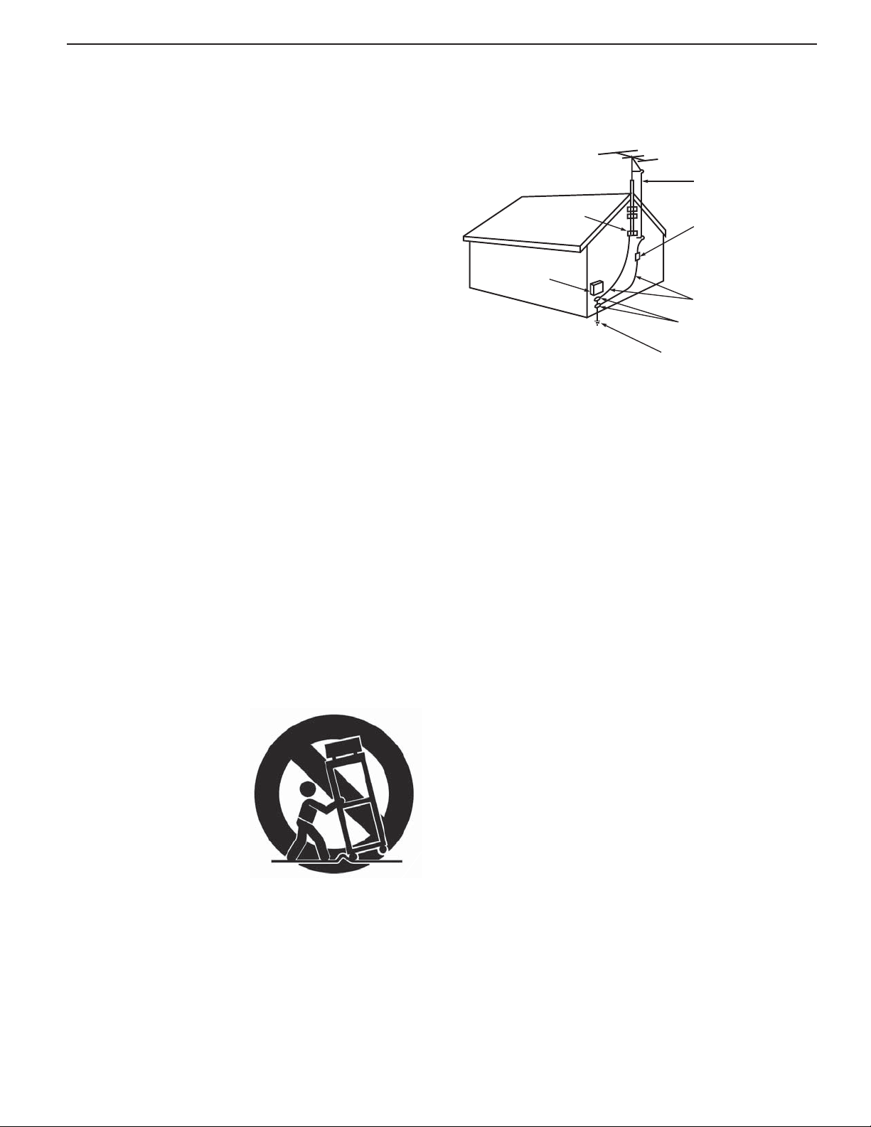
EXAMPLE OF ANTENNA GROUNDING
ANTE NNA
LEAD IN WIRE
GROUND CLAMP
ELECTRIC
SERVICE
EQUIPMENT
NEC — NATIONAL ELECTRICAL CODE
ANTE NNA
DISCH AR G E UNIT
(NE C AR TIC LE 810-20)
GROUNDING
CONDUCTORS
(NEC ARTICLE 810-21)
GROUND CLAMPS
POWER SERVICE GROUNDING
ELECTRODE SYSTEM
(NE C AR T 250, P AR T H)
Outdoor Antenna Grounding
If an outside antenna or cable system is connected
to the TV, be sure the antenna or cable system is
grounded so as to provide some protection against
voltage surges and built-up static charges.
Replacement Parts
When replacement parts are required, be sure the
service technician has used replacement parts specified by the manufacturer or have the same characteristics as the original part. Unauthorized substitutions
may result in fire, electric shock or other hazards.
11) Only use attachments/accessories specified by the
manufacturer.
12) Use only with the cart,
stand, tripod, bracket,
or table specified
by the manufacturer,
or sold with the
apparatus. When
a cart is used, use
caution when moving
the cart/apparatus
combination to avoid
injury from tip-over.
13) Unplug this apparatus
during lightning storms or when unused for long
periods of time.
14) Refer all servicing to qualified service personnel.
Servicing is required when the apparatus has been
damaged in any way, such as power-supply cord or
plug is damaged, liquid has been spilled or objects
have fallen into the apparatus, the apparatus has
been exposed to rain or moisture, does not operate
normally, or has been dropped.
Page 6

6
Special Features of Your TV
Your new high-definition widescreen television has
many special features that make it the perfect center of
your home entertainment system, including:
1080p High-Definition DLP Display System
Your Mitsubishi HDTV uses Texas Instruments Digital
Light Processing™ technology for rear-projection TVs
to create the picture you see on screen. All images are
displayed at 1080p. The TV uses Plush 1080p® 5G to
convert lower-resolution signals to 1080p for display.
The TV can also accept 1080p original signals and
maintain them at 1080p through all processing until
displayed.
3D Ready
All Mitsubishi 1080p DLP HDTV’s are 3D Ready. This
feature lets you experience the new 3D technologies applied to many recent movies and video games.
Immerse yourself in your favorite video game, movie, or
sporting event displayed in 3D.
16:9 Widescreen Picture Format
Enjoy a full theatrical experience in the comfort of your
home. View pictures as film directors intended them.
Digital TV broadcasts, DVDs and newer video game
consoles support this widescreen format.
Integrated HDTV Tuner
Your widescreen Mitsubishi HDTV has an internal HDTV
tuner able to receive both over-the-air HDTV broadcasts (received via an antenna) and non-scrambled
digital cable broadcasts, including non-scrambled
HDTV cable programming.
High-Definition Video Inputs
Component Video Inputs.• Also called Y/Pb/Pr
inputs, these inputs receive standard analog video
formats of 480i, 480p, 720p, and 1080i high-definition signals. This provides a high level of flexibility
when connecting DVD players/recorders, cable
boxes, and satellite receivers.
HDMI Inputs.• These inputs accept digital 480i,
480p, 720p, 1080i, and 1080p video signals plus
PCM digital stereo signals. The HDMI™ inputs can
also accept a variety of PC signals and resolutions.
These inputs support HDMI 1.3 Deep Color (up to
36 bits) and the x.v.Color extended color gamut.
Used with an adapter, these HDMI inputs also
accept compatible digital DVI video signals. HDMI
inputs provide additional high-performance,
high-definition connections for maximum flexibility
in your choice of home theater products. The HDMI
inputs are HDCP copy-protection compatible.
Easy Connect Auto Input Sensing
Easy Connect™ Auto Input Sensing automatically recognizes when you plug in a device and prompts you to
assign a name to it. The TV ignores any unused inputs,
so the result is an uncluttered menu where you can
easily find and select connected devices by name.
Home-Theater Control
HDMI Control
Available for all models. HDMI devices with Consumer Electronics Control (CEC) capabilities may be
compatible with the TV’s HDMI Control feature. Compatible devices can receive control signals through the
HDMI connection, allowing the TV’s remote control to
operate some functions of these devices.
Net Command with IR Learning
837 Series. Your Mitsubishi HDTV offers a new level
of networking that seamlessly integrates selected
older A/V products with new and future digital products. Net Command
products such as VCRs, DVD players, cable boxes, and
satellite receivers. Net Command can “learn” remote
control signals directly from many devices, allowing you
to create a customized NetCommand-controlled hometheater system. The necessary IR emitter cables are
available for purchase separately from Mitsubishi.
®
supports IR (infrared) control of
ENERGY STAR® Compliance
This TV meets ENERGY STAR® efficiency standards in
all operating modes.
Page 7
1
7
Basic Setup and Operation
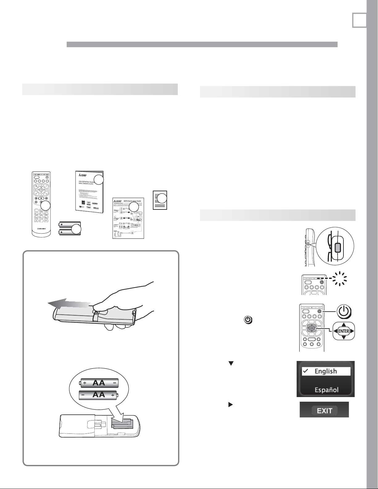
Package Contents
Please take a moment to review the following list of
items to ensure that you have received everything.
1. Remote Cont rol
2. Two AA Batteries
3. Basic Owner’s Guide
4. HDTV Quick-Setup Guide
5. Product Registration Card
ACTIVITY
GUIDE MENU INFO BACK
1
AA
2
AA
3
5
4
R emote Control Batteries
Remove the remote control back cover.1.
Before You Begin
Review the important safety, installation, and oper-
1.
ating information at the beginning of this book.
Choose a location for your TV.
2.
• Allow at least four inches of space on all sides
of the TV to help prevent overheating. Overheating may cause premature failure of the TV
as well as shortened lamp life.
• Avoid locations where light may reflect off the
screen.
• See the stand requirements on page 2 .
Install the batteries in the remote control.
3.
Plug the TV into an AC power outlet.
4.
First-Time Power-On
Confirm that the remote
1.
control is in TV mode.
Press the side button •
once to light the mode
indicator and confirm
that
TV
mode is active.
To change, press the •
side button additional
times to activate
mode.
Aim the remote control
2.
at the TV and press the
POWER
key . Wait for the
Welcome screen.
TV
GUIDE MENU INFO BACK
GUIDE MENU INFO BACK
TV
Load the batteries, making sure the polarities 2.
(+) and (-) are correct. Insert the negative (-)
end first.
Slide the cover back into place.3.
Press
3.
change the menu language
to Español.
Press
4.
Press
menu.
if you wish to
to highlight EXIT.
ENTER
to clear the
Page 8
8 1. Basic Setup and Operation
TV Controls
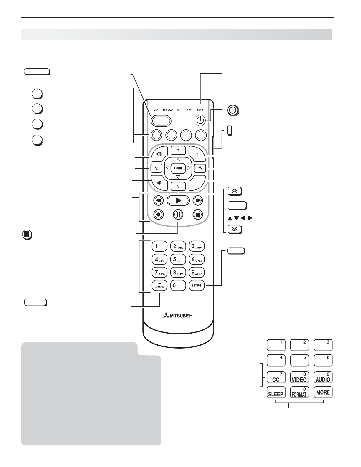
Re mote Control
ACTIVIT Y
Press to select a TV activity
and input. See page 21 .
GUIDE
ChannelView listings, page 22
MENU
TV main menu, page 32
INFO
TV status (
Steps back one menu; clears
BACK
the top menu or Status Display.
page 23 )
or TV help.
.
VOLUME UP
MUTE
VOLUME DOWN
Record/Playback controls for external devices
When remote control is programmed, page 59
HDMI control, page 68
837 Series: NetCommand, page 48
(
PAUSE
)
Freezes a broadcast TV picture.
ACTIVITY
GUIDE MENU INFO BACK
VCR CABL/SAT TV DVD AUDIO
Control-mode indicator for device
type to control. Use the side button to
change.
Powers TV on or off.
Side button sets the control mode
for the type of device to operate. Set
mode to TV for normal TV viewing.
CHANNEL UP
.
Goes to the previously tuned channel.
LAST
CHANNEL DOWN
PAGE UP
ENTER
Selects a channel number or
menu item.
Navigation controls
PAGE DOWN
Number/letter keys
Channel tuning, page 12
—
CANCEL
Adds a separator when entering digital channel numbers.
Clears some menu entries.
Note: To operate other audio/video
devices using the TV’s remote
control:
• See Appendix B , “ Programming the Remote
Control .”
• For HDMI devices compatible with the TV’s
HDMI Control feature, see Appendix C .
• 837 Series
See - page 45 for Net Command IR “Learn-
ing” of device keys.
For use of specific keys with NetCom- -
mand-controlled devices, see “Special
Operation Methods,” page 48 .
CC
Closed captions, page 37
VIDEO
Video adjustments, page 35
AUDIO
Audio adjustments, page 36
SLEEP
FORMAT
MORE
MORE
Displays a menu showing additional functions for the number
keys.
For the •
MORE
menu in TV mode,
see below.
With remote control programmed •
for other device types, page 59 .
The
MORE
menu in other modes is
specific to the device type.
For CEC-enabled devices, • page 66
The MORE menu in TV mode
Sleep Timer, page 21
Picture shape (aspect ratio), page 24
Clears
the MORE menu.
Page 9
1. Basic Setup and Operation 9
POWER
STATUS
TV Controls, continued
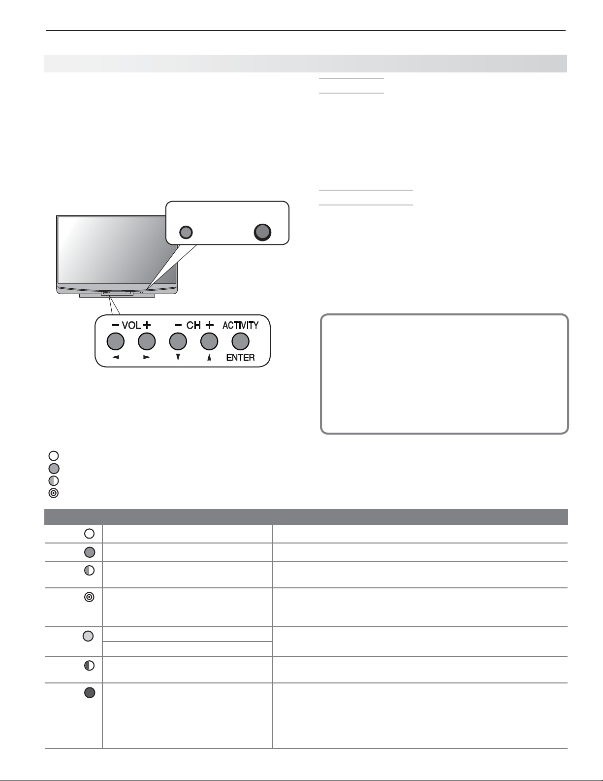
TV Control Panel
Buttons on the control panel duplicate some keys on
the remote control.
Refer to • upper labels when no TV menus are displayed.
Refer to • lower labels when using TV menus or after
activating a special function.
737 and C9 series.
Flip open cover to
use buttons on the
front panel.
Controls on 737 and C9 series TVs. 837 series controls
are similar and are located next to the
STATUS
indicator.
STATUS Light
Key
Off
Steady On
Slow Blinking
Fast Blinking
System Reset
If the TV fails to respond to the remote control, the
control-panel buttons, or will not power on/off, perform
System Reset. Recent setting changes made before
using System Reset may be lost.
To perform System Reset, press and hold the
button on the control panel for ten seconds.
Panel-Lock Release
To • release the Panel Lock from the TV control
panel, press and hold the
control panel for ten seconds. You can release the
Panel Lock with the TV powered either on or off.
To activate the Panel Lock, use the • Lock menu,
page 44 .
If You Power Off the TV by Mistake
1. Press
2. If the status indicator starts rapidly blinking
POWER
again, within about 60 seconds,
to have the TV come back on immediately.
green (about 60 seconds after you shut off
power), wait a few moments for the status indicator to stop blinking and press
the TV on again.
ACTIVIT Y
button on the
POWER
POWER
to turn
LED Color TV Condition Additional Information
None
Green
Green
Green
Yellow
Red
Red
TV is powered off.
TV is powered on.
TV powered off, auto-on TV Timer
is set.
TV just powered off and lamp is
cooling.
Lamp failure1. Replace the lamp. See “Lamp-Cartridge Replacement and
No lamp installed.2.
Lamp access door is open or not
secure.
TV may require service.
Normal operation.
Normal operation.
Normal operation. TV can be turned on at any time.
LED starts to blink 60 seconds after turning off TV. TV can be
turned back on before blinking starts or after blinking stops, but
not while the indicator is blinking. Normal operation.
Cleaning” on page 69 .
TV will not operate until lamp access door is secured. See
“Lamp-Cartridge Replacement and Cleaning” on page 69 .
Turn off the TV and unplug the set from the AC power source.
Wait one minute and then plug the set back in. See Appendix E .
If the red LED is still on, contact your dealer or a Mitsubishi
Authorized Service Center. Go to www.mitsubishi-tv.com or call
1-800-332-2119 to receive Authorized Service Center information.
Page 10
10 1. Basic Setup and Operation
Settin g Up TV Inputs
Using the ANT (Antenna) Input
If using an antenna or direct cable service (no cable
box), connect the incoming coaxial cable to the TV’s
ANT
input. Refer to page 18 .
You must save channels to memory with a channel scan
to enable reception of all available high-definition and
standard-definition digital channels. The channel scan
will search for channels available locally. If you skip this
step, the TV will receive only analog channels.
M emorizing Channels with Channel Scan
For the ANT input
To start channel memorization
Power on the TV.
1.
Press
2.
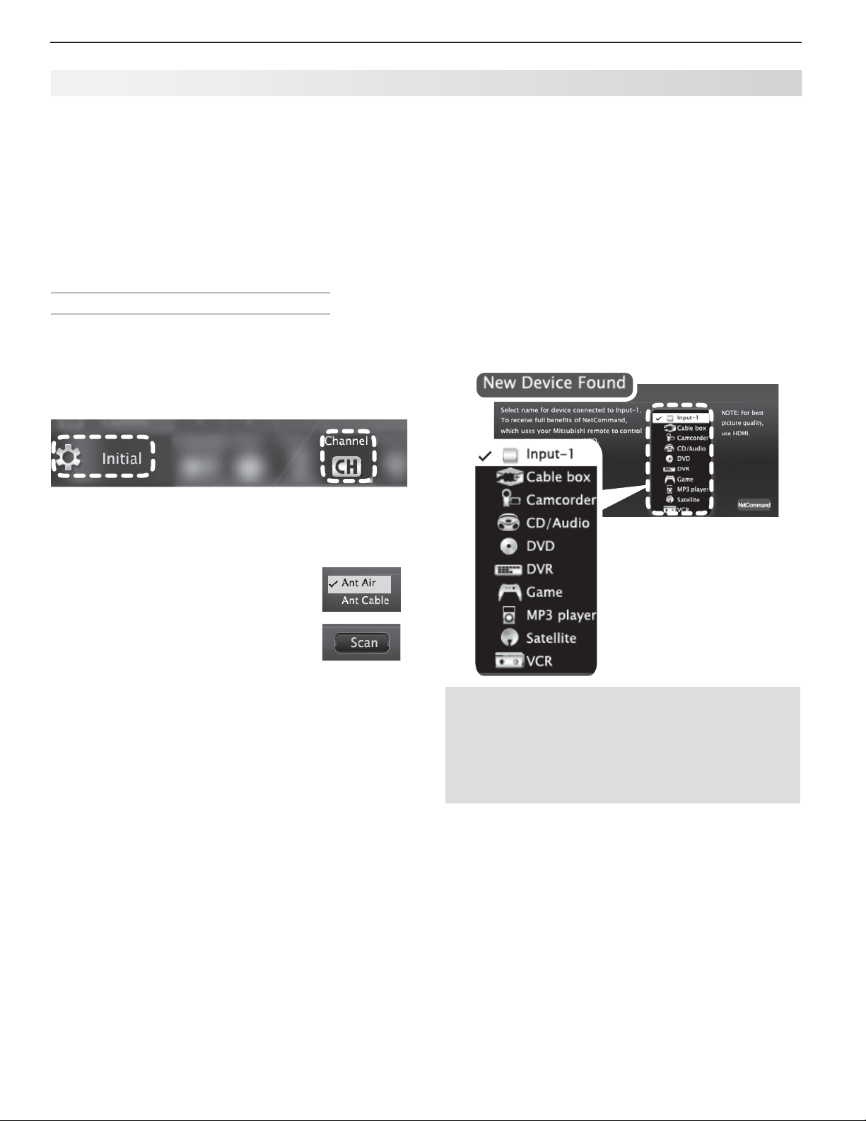
Start channel memorization from the Initial > Channel
menu.
MENU
and open the Initial > Channel menu.
Setting Up Other Inputs
Connect your devices to the TV, making note of
1.
which TV input jack is used for each device. See
“TV Connections,” page 14 , for recommendations.
Power on the devices to ensure detection.
2.
Power on the TV.
3.
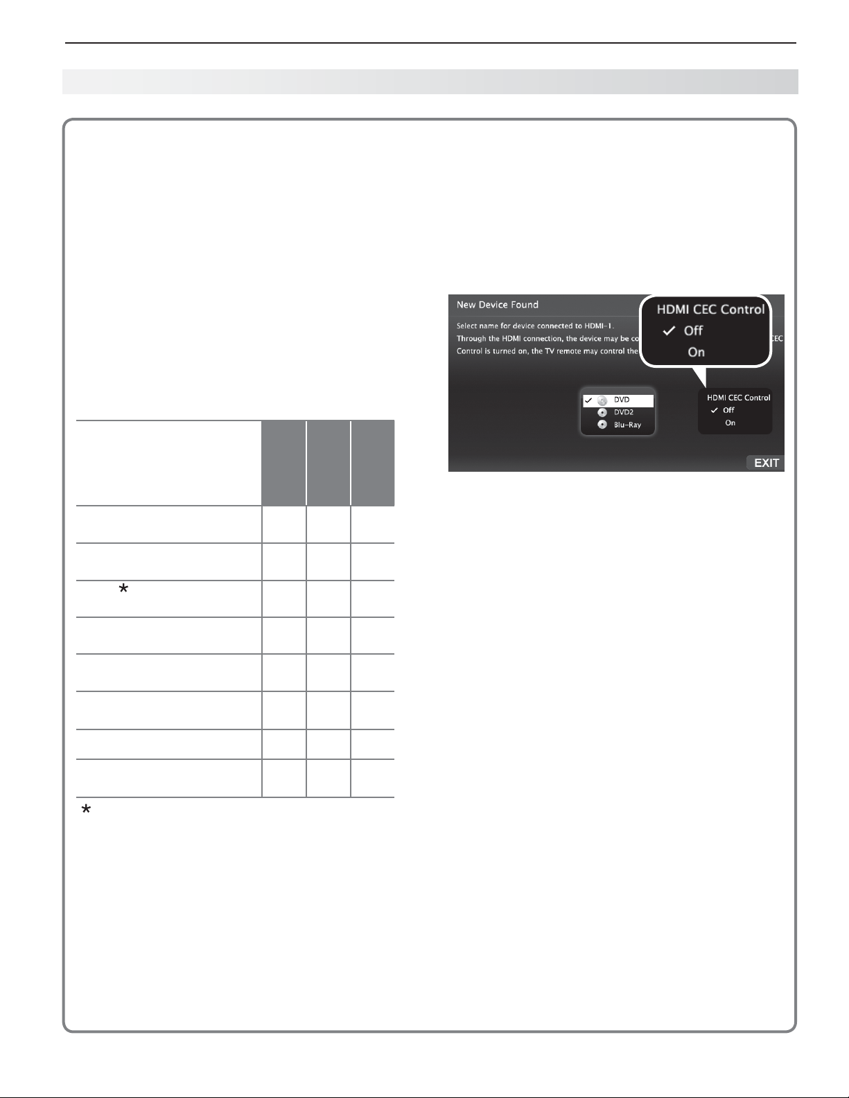
The TV will display the New Device Found screen
for each new connection it detects Learn more
about Auto Input/Auto Output Sensing on the
opposite page .
Select the device type if the device is not recog-
4.
nized automatically.
Press
3.
4.
5.
To stop channel memorization before completion,
press
Use the Initial > Channel > Edit menu ( page 39 ) for
additional channel options, such as adding or deleting
channels from memory.
ENTER
to enter the menu.
Select
over-the-air antenna. Select Ant
Cable for direct cable.
Highlight
Channel memorization may take up
to 15 minutes to complete.
Ant Air if connected to an
Scan and press
CANCEL
.
ENTER
.
Sample New Device
Found screen.
Important Note for NetCommand IR Users
837 Series. Be sure to select the correct device
type here. Although you can change the device type
later in the Inputs > Name menu, any “learned” Net Command IR codes will be erased when you make
the change.
837 Series.
5.
“learning” after selecting the device type or at a
later time when convenient. To perform now, highlight NetCommand and press
NetCommand Setup,” page 47 or “Setting Up A/V
Receiver Control,” page 52 .
Press
6.
BACK
The TV will then display the New Device Found
screen for the next connection it finds.
You can perform Net Command IR
ENTER
. See
“Initial
to close the New Device Found screen.
Page 11
1. Basic Setup and Operation 11
Setting Up TV Inputs, continued
About Auto Input S ensing/
Auto Output Sensing
This TV’s Easy Connect™ Auto Input Sensing feature
detects most connections automatically.
Auto Input/Auto Output Sensing for Most Devices
When you first connect a device, the TV will:
a. Detect the connected device and automati-
cally switch to it.
b. Prompt you to identify the device type.
c. 837 Series. Prompt you to perform Net Com-
mand set-up for the device, if available.
d. Repeat these steps for any other newly
detected devices.
Which Jacks Trigger Auto Sensing?
TV Jacks and
Auto Sensing
Auto Input
Sensing
Auto Output
Sensing
No Auto
Sensing
Y/V I D EO
composite video)
Y/V I D EO
as component video)
HDMI
USB
DIGITAL AUDIO OUTPUT
(orange jack)
AVR AUDIO OUTPUT
(
red jack)
ANT
IR NetCommand Output
(837 series)
The TV cannot detect an HDMI device when
(detected as
plus Pb (detected
9
9
9
(837 series)
(Antenna)
9
9
9
9
the device is powered off
occur when the device is next powered on.
. Detection will
9
For an HDMI A/V receiver, select - AVR from
the list of device types if the A/V receiver is
not recognized automatically.
HDMI CEC Devices Compatible with the TV’s •
HDMI Control Feature.
enabled HDMI devices are often recognized automatically by the TV.
to control some functions of a CEC-enabled device.
See Appendix C , “ HDMI Control of CEC Devices .”
New Device Found screen for a device with HDMI
control enabled. Select On to enable the TV’s CEC
control of the device. In some cases, as in the
example above, you will also be prompted to select a
device name.
Tips on Auto Sensing
Choose a different name for each input.•
The antenna input (•
although you can turn off the unused antenna
input in the Inputs > Name menu.
Change the device type displayed in the • Activity
menu by using the Inputs > Name menu ( page
40 ).
837 series.• Any “learned” Net Command IR
codes will be erased if you change the device
type in the Inputs > Name menu.
Reactivating Auto Input Sensing
for an HD MI Input
When you disconnect an HDMI device, Auto Input
Sensing is disabled until you perform these steps.
Compatible CEC-
HDMI Control may allow you
ANT
) is never detected,
When You First Connect a Device
Most Device Types.• Select the device type from
the on-screen list. The device type you select here
will appear as a device icon in the Activity menu.
A/V Receiver•
The TV can detect audio connections on the -
DIGITAL AUDIO OUTPUT jack and the right (red)
AVR AUDIO OUTPUT jack.
Disconnect the HDMI device.
1.
Delete the removed HDMI device in the
2.
Name menu (see “Removing an HDMI Device,”
page 68 ).
Connect the new device and the
3.
Found screen will display.
New Device
Inputs >
Page 12
12 1. Basic Setup and Operation
Basic TV Operation
Selecting an Input to Watch
Press
1.
2.
3.
Press
Press
ACTIVIT Y
ENTER
.
and to highlight an input.
to switch to the input.
Wa tching Broadcast TV
TV Connected to an Antenna, Direct Cable, Cable
Box, Set-Top Box, or Satellite Receiver
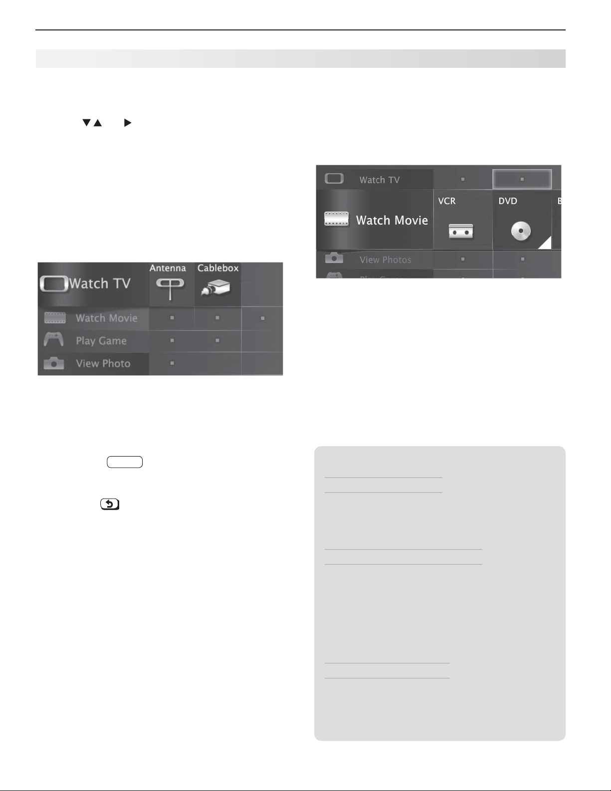
Select an input to watch from the
1.
Watch TV group.
Note: For more about the Activity menu, see page 21 .
Activity menu’s
Watching DVDs or Videos
TV Connected to a DVD Player, DVR, or VCR
Press
ACTIVIT Y
Activity menu. If you named devices during Auto Input
Sensing, select the input from the Watch Movie group.
Activity menu, DVD input selected
and select a movie source from the
Activity menu, antenna input selected
Tune to a channel.
2.
Enter the channel number using the number •
keys on the remote control and press
For a two-part digital channel, such as 3-1,
press
Press •
nels one channel at a time.
Press •
ously tuned channel.
Antenna or Direct Cable Only.• Press
display ChannelView channel listings, highlight
a channel number, and press
—
3
CANCEL
CHANNEL UP/CHANNEL DN
1 to enter a dash (separator).
(LAST)
to switch back to the previ-
ENTER
.
to change chan-
GUIDE
ENTER
to tune.
to
TV Tips
Turning the TV On or Off
Point the remote control at the front of the TV •
and press the
Press the •
panel.
If You Turn Off the TV by Mistake
Press •
POWER
to have the TV come back on immediately.
If the status indicator starts rapidly blinking •
green (about 60 seconds after you shut off
power), wait a few moments for the status indicator to stop blinking and press
the TV on again.
Controlling Sound Volume
Press •
VOLUME UP/VOLUME DN
level.
See also • “Controlling A/V Receiver Sound
Volume” on page 22 .
POWER
button.
POWER
button on the TV control
again, within about 60 seconds,
POWER
to adjust the sound
to turn
Page 13

1. Basic Setup and Operation 13
Basic TV Operation, continued
Making Picture Adjustments
To get the best picture under different viewing con-
1.
ditions, set the Picture Mode before changing other
video settings. See page 35 for more.
a. Press
b. Make one of these selections:
c. Press
Press
2.
Press
3.
Press
4.
you want.
Press
5.
Additional picture adjustments are described on pages
34 and 35 .
MENU
and go to the Adjust > Picture >
Picture Mode menu.
Name When to Use
Brilliant
Game
Bright For most daytime viewing
Natural For most nighttime viewing
MENU
MORE
8
(VIDEO).
to display the name of the adjustment
to make the adjustment.
Under bright light
With gaming consoles
to clear the menu.
.
Audio Settings
Other TV Features
Activate Audio Lock to control your sound system •
with the TV’s remote control left in TV mode. See
page 60 .
To set the TV Clock see • page 38 . Set the TV
Clock if you plan to use the TV Timer ( page 38 ) or
ChannelView ( page 22 ) features.
To set parental controls, see the • Lock menu, page
42 .
To change the input names that appear in the •
Activity menu, see Inputs > Name options, page
40 .
3D Video.• See page 25 .
To program the remote control to operate other •
A/V devices, see Appendix B , “Programming the
Remote Control,” page 59 .
To control compatible devices using HDMI CEC •
control, see Appendix C , “HDMI Control of CEC
Devices,” page 66 .
837 Series.• To view still and moving digital camera
images on the TV, see “Camera Images and Music
Files,” page 28 .
837 Series.• To control A/V devices with Net Com-
mand, see chapter 5, “NetCommand IR Control for
Most Devices” on ( page 45 ).
Changing the Audio Output
To switch audio output from the internal TV speakers to
a connected external sound system or headphones:
Press
1.
2.
3.
4.
Changing Audio Settings
1.
2.
3.
4.
MORE
.
Press
9
(AUDIO).
Press
The Speakers option will display only if a connec-
tion has been detected on one of the TV’s audio
outputs.
Press
Receiver or Headphones.
Press
Press
Press
you want.
Press
until the Speakers option is displayed.
to switch between TV and either AV
MORE
.
9
(AUDIO).
to display the name of the adjustment
to change the setting.
Other Information
TV Care
Lamp Cartridge.• When the lamp cartridge needs
replacement, replace the lamp yourself and save
the cost of a service call. See Appendix D for
instructions.
General Cleaning.• See “Cleaning Recommenda-
tions,” page 71 .
Assistance
For troubleshooting, service, and product support, •
see Appendix E , page 72 .
For warranty information, see the TV warranty on •
page 81 .
Page 14
14
2
Before You Begin
TV C onnections
Auto Input Sensing
The TV’s Auto Input Sensing feature automatically recognizes most connections and prompts you to identify
the type of device connected. See page 11 for more on
Auto Input Sensing.
Connection Types
Use the connection types available on your input
devices that will give the best video quality. For
example, choose HDMI over component video, and
choose component video over composite video.
Picture Quality
For best picture quality, route signals directly from the
input device to the TV whenever possible.
Surround Sound
For best surround sound audio quality, route audiosignal cables or HDMI cables from the source device
directly to your A/V receiver or sound system.
IMPORTANT
Accessory items such as cables, adapters,
splitters, or combiners required for TV
connections are not supplied with the TV.
These items are available at most electronics
stores.
Page 15
2. TV Connections 15
1
2
3
HDMI
AVR
AUDIO
OUTPUT
L
R
Pb
Y/ VIDEO
Pr
Pb
Pr
INPUT 2
INPUT 1
DIGITAL
AUDIO
OUTPUT
DVI/PC
AUDIO
(480i / 480p / 720p / 1080i)
L
R
L
R
INPUT
AUDIO
Y/ VIDEO
3D
GLASSES
EMITTER
ANT
RS-232C
IR-
NetCommand
Output
R
RS-2
USB HDMI 4
INPUT 3
AUDIO
LR
Pb
Y/ VIDEO
Pr
USB
HDMDMI 4
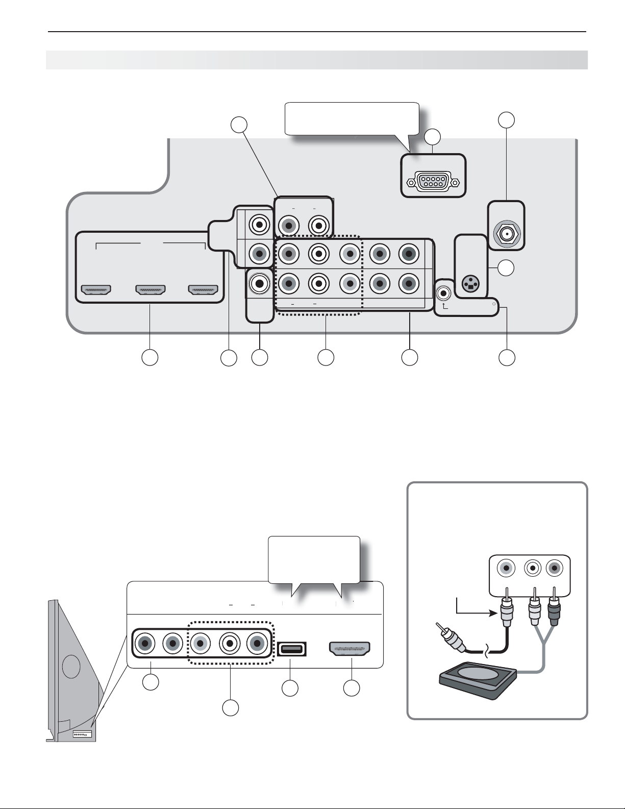
Inputs and Outputs
Main Connection Panel
DVI/PC INPUT
2
HDMI
( page 17 )
( page 18 )
AVR
AUDIO
OUTPUT
( page 20 )
6
8 34
7
DIGITAL
AUDIO
OUTPUT
( page 20 )
RS-232C control jack
offered on 837 series.
VIDEO
(composite
video, page 19 )
10
Y Pb Pr
(component
video, page 17 )
ANT
1
( page 18 )
3D GLASSES
5
EMITTER
( page 25 )
9
IR–NetCommand Output
( page 46 )
Offered on 837 series.
Convenience Inputs
A readily accessible set of jacks is provided for a camcorder, game, or
other audio/video device.
837 Series. A fourth HDMI input is provided. If you connect a DVI
device to the HDMI input, use the nearby audio jacks to send sound
from the device to the TV.
3
Y Pb Pr
(component
video, page 17 )
4
VIDEO
(composite video,
page 19 )
USB port and
HDMI 4 offered
on 837 series.
( page 28 )
11
USB
2
HDMI
( page 17 )
Using an A udio- Only Device
Keep an unused RCA-style connector in the
Y/V I D EO
using an audio-only device.
Unused
RCA-style plug
(plug in first)
Y/VIDEO
1.
jack while
L-AUDIO-R
2.
Audio-only
device
Page 16

16 2. TV Connections
Inputs and Outputs, continued
1. ANT ( Antenna)
Connect your main antenna or direct cable service (no
cable box) to
and analog over-the-air channels from a VHF/UHF
antenna or non-scrambled digital/analog cable source.
2. HDMI™ Inputs
ANT
. The
ANT
input can receive digital
(High-Definition
Multimedia Interface)
The HDMI inputs support uncompressed standard and
high-definition digital video formats and PCM digital
stereo audio.
Mitsubishi recommends you use category 2 HDMI
cables, also called high-speed HDMI cables, to connect
HDMI 1.3 source devices. High-speed category 2 cables
bring you the full benefits of Deep Color and x.v.Color.
These HDMI inputs can also accept digital DVI video
signals. To connect a device’s DVI output to the TV’s
HDMI input, use an HDMI-to-DVI adapter or cable plus
analog audio cables. Connect the analog audio cables to
the
DVI/PC INPUT AUDIO
and right stereo audio from your DVI device.
Use the HDMI inputs to connect to CEA-861 HDMI compliant devices such as a high-definition receiver or DVD
player. These inputs support 480i, 480p, 720p, 1080i,
and 1080p video formats.
The TV’s HDMI inputs are compatible with many DVI-D
and HDMI computer video signals.
These inputs are HDCP (High-Bandwidth Digital Copy
Protection) compliant.
jacks on the TV to receive left
3. Y Pb Pr (Component Video)
Connect devices with component video outputs to this
jack. Use the adjacent
to send audio to the TV.
4.
VIDEO
Connect a VCR, DVD player, standard satellite receiver,
or other A/V device to the TV. Use the adjacent
R
and L inputs if you wish to send audio to the TV.
(Composite Video)
AUDIO R
and L jacks if you wish
AUDIO
5. 3D GL ASSES EMITTER
Use this jack for the special IR emitter supplied with 3D
glasses. The emitter will send a signal that synchronizes
your 3D glasses with the screen display. See page 25
6. DVI/PC INPUT AUDIO
When connecting a DVI device to one of the TV’s HDMI
inputs, use these jacks for left and right analog audio.
7. AV R AUDIO OUTPUT
Use
AVR AUDIO OUTPUT
current program to an analog A/V surround sound
receiver or stereo system. Digital audio from digital
channels and HDMI devices is converted to analog
audio by the TV for output on this jack. This is the only
audio connection needed to the TV if using an analog
A/V receiver or stereo system.
Headphones. The audio right (red) jack can also be
used for headphones that accept standard line level
audio signals.
to send analog audio of the
H DMI Cable Categories
HDMI cables are available as Category 1 and Category 2 types.
Category 2 Cables• (also called high-speed
HDMI cables). Newer, HDMI 1.3-compliant DVD
players, video games, and set-top boxes require
Category 2 cables, suitable for clock frequencies up to 340 MHz or data rates of up to 10.2
gigabits per second. Use category 2 cables for
high-speed 1080p HD signals carrying extended
color encodings (i.e., 30 or more bits, also called
Deep Color). Category 2 cables are also suitable
for standard HDTV signals.
Category 1 Cables• (also called standard HDMI
cables). Category 1 cables may be unmarked.
They are suitable for standard HDTV 720p,
1080i, and 1080p signals with 8-bit color depth.
Use category 1 cables for clock frequencies up
to 74.25 MHz or data rates of up to 2.23 gigabits
per second.
8. DIGITAL AUDIO OUTPUT
This output sends Dolby Digital or PCM digital audio
to your digital A/V surround sound receiver. Incoming
analog audio is converted by the TV to PCM digital audio.
If you have a digital A/V receiver, in most cases this is the
only audio connection needed between the TV and your
A/V receiver.
9. IR–Net Command Output
837 Series. Connect IR emitters to this jack to send
control signals to external IR remote-controlled devices.
10. RS-232C
837 Series. Use the RS-232C interface to receive
control signals from compatible home-theater control
devices. See www.mitsubishi-tv.com for a list of
control signals for this interface.
11. USB (837 Series)
The TV can read JPEG photo files and mp3 or wma music
files from a USB device connected to the USB port.
Page 17
2. TV Connections 17
I
O
OUTPUT
R
P
b
Y/
E
O
P
r
P
b
U
U
1
DIG
AUDIO
O
T
DVI/PC
O
(
)
()
R
INPUT
AUDIO
Y/ VIDE
O
3D
GLASSES
ANT
RS
C
IR
NetCommand
Output
O
O
T
R
b
Y
E
O
b
D
L
AUDIO
OUTPU
D
C
O
(
)
(pp)
L
R
R
INPUT
AUDIO
Y/ VIDE
O
3D
G
E
R
RS-232C
I
NetCommand
Output
H
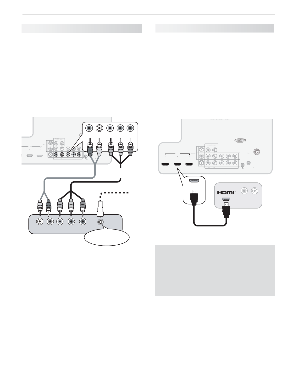
Y Pb Pr Co mponent Video Device
D MI Device
HDTV Cable Box, Sa tellite Receiver, DVD/
Blu-ray Player
If your cable box or satellite receiver has an HDMI
output, use the connections for HDMI devices
described on this page .
Required:
RCA-type component video cables
Left/right analog audio cables.
Note:
To hear digital surround sound, connect the digital
audio output from the device directly to your digital
A/V receiver.
L
AUDIO
AUDI
OUTPUT
UTPU
R
DIGITAL
IGITA
AUDIO
OUTPUT
T
TV main panel
DVI/PC
VI/P
R
R
R
AUDIO
– AUDIO –
AUDIO
AUDI
INPUT
L
L
L
Y/ VIDEO
/ VID
Y/ VIDEO
Y/ VIDEO
(480i / 480p / 720p / 1080i)
480i / 480p / 720p / 1080i
RS-232C
R
Pr
Pb
Pb
Pb
GLASSES
EMITTER
NPUT 2
INPUT 2
NPUT 1
INPUT 1
Pr
Pr
IR-
R-
Output
– AUDIO –
3D
LASSES
MITTE
NetCommand
Y/ VIDEO
L
ANT
ANT
R
Component
video cables
Audio
cables
Pb
HDTV Cable Box, Satellite Receiver, DVD/
Blu-ray Player
Required: HDMI-to-HDMI cable.
Connect an HDMI cable from the TV back panel to the
HDMI device output. HDMI devices provide video and
audio through the single cable.
Mitsubishi recommends you use category 2 (highspeed) HDMI cables to connect HDMI 1.3 source
devices. High-speed category 2 cables bring you the
full benefits of Deep Color and x.v.Color. See “HDMI
Cable Categories” on the opposite page for more on
HDMI cable types.
Pr
TV main
panel
HDMI
HDM
HDMI
1
-232
RS-232C
DVI/PC
INPUT
AUDIO
L
R
L
AVR
AUDIO
AUDI
OUTPUT
2
R
3
DIGITAL
ITAL
AUDIO
UTPU
OUTPUT
Y/ VIDEO
VID
Y/ VIDEO
L
R
AUDIO
AUDI
Pr
Pb
Pr
Pb
(480i / 480p / 720p / 1080i)
480i / 480p / 720p / 1080i
T 2
NP
INPUT 2
T
INPUT 1
INP
GLASSES
EMITTER
IR-
NetCommand
-
Output
ANT
3D
R
L
R
AUDIO
Component video
device
Incoming from
cable service or
satellite dish
PbYPr
CABLE IN or
SATELLITE IN
RL
AUDIO
AUDIO
HDMI-to-HDMI
cable
Any HDMI
device
IMPORTANT
HDMI and Audio Signals
Digital Surround Sound: The TV’s HDMI inputs
can receive digital stereo audio signals only. To
hear digital surround sound from an HDMI device,
connect the device’s HDMI or digital audio output
directly to your A/V receiver. See the Owner’s
Guides for those devices for instructions.
Page 18
18 2. TV Connections
2
3
O
O
T
R
b
Y/
E
O
P
b
P
r
2
U
1
L
AUDIO
OUTPUT
O
(
)
()
L
R
INPUT
AUDIO
Y/ VIDE
O
3D
GLASSES
EMITTER
ANT
IR
NetCommand
Output
P
r
2
U
1
)
)
3
GLASSES
EMITTER
ANT
RS-232C
NetCommand
t
R
3
O
O
b
E
O
b
U
1
DVI/PC
O
(
)
(pp)
L
R
R
O
Y/ VIDE
O
3
GLASSES
C
IR
NetCommand
Output
R
COMPOS
V
OUT
L
R
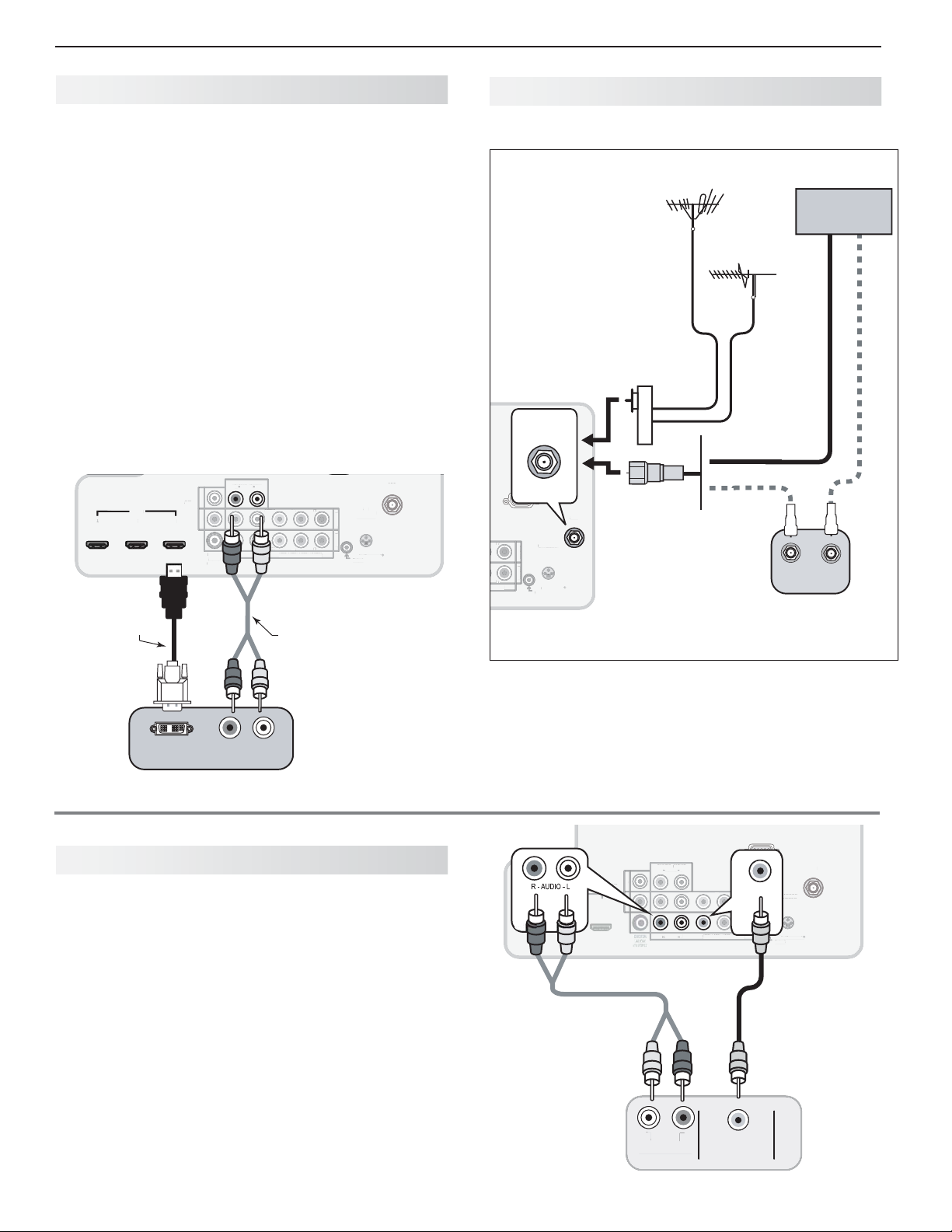
DV I Video Device
Ante nna or Cable TV Service
Cable Box, Satellite Receiver, DVD Player
Connect DVI devices (digital only) to the TV’s HDMI
input jacks.
Required:
Analog stereo audio cables
DVI-to-HDMI cable or DVI/HDMI adapter and HDMI
cable
If you are using a DVI/HDMI adapter, it is important to
connect the adapter to the DVI device for best performance.
Some devices require connection to an analog input
first in order to view on-screen menus and to select DVI
as the ouput. Please review your equipment instructions for DVI connectivity and compatibility.
Note: The HDMI connection supports copy protection
(HDCP).
INPUT
INPUT
DVI/PC
DVI/PC
HDMI
HDMI
2
2
1
1
DVI-to-HDMI
cable
DVI/PC
AUDIO
AUDIO
L
L
R
R
L
AVR
AUDIO
AUDI
OUTPUT
UTPU
R
3
3
DIGITAL
DIGITA
AUDIO
OUTPUT
Y/ VIDEO
Y/ VIDEO
L
R
AUDIO
AUDI
VID
Pb
Pb
(480i / 480p / 720p / 1080i)
480i / 480p / 720p / 1080i
Pr
NPUT
INPUT 2
T
NP
INPUT 1
Pr
TV main panel
Audio cables
GLASSES
EMITTER
IR-
Output
-
3D
NetCommand
ANT
R
Connect the incoming cable to the TV’s
VHF
antenna
UHF
antenna
300-ohm-to75-
ohm combiner
(side view)
ANT
or
or
Older
cable
box
p / 1080i)
p / 1080i
RS-232C
ANT
ANT
3D
Pr
Pr
D
GLASSES
EMITTER
INPUT 2
INPUT
T
INPUT 1
INP
IR-
NetCommand
Outpu
Output
R
TV main
panel
Not recommeded. Other
connection types provide
better quality audio and video.
ANT
input.
Cable TV
service
Direct cable (no cable box)
OUT
IN
DVI OUT
RL
AUDIO
Digital DVI
device
Comp osite Video Device
VCR or other device with composite video
output
Required:
Composite video cable (usually yellow)
Analog stereo audio cables.
TV main panel
HDMI
2
1
3
Audio
cables
VCR or other
device with
composite
video output
AVR
AUDI
AUDIO
OUTPUT
UTPUT
L
R
INPUT
INPUT
DVI/PC
AUDIO
AUDI
L
L
R
Y/ VIDEO
Y/ VID
Y/ VIDEO
Y/ VIDEO
L
R
AUDIO
AUDI
L
L
R
R
AUDIO OUT
AUDIO OUT
AUDIO OUT
RS-232
RS-232C
Y/ VIDEO
Pr
Pb
T 2
NP
INPUT 2
NPUT
INPUT 1
Pr
Pb
(480i / 480p / 720p / 1080i)
480i / 480p / 720p / 1080i
Composite
video cable
ITE
COMPOSITE
COMPOSITE
IDEO
VIDEO OUT
VIDEO OUT
GLASSES
EMITTER
IR-
Output
-
3D
D
NetCommand
ANT
R
Page 19
2. TV Connections 19
L
AUDIO
ANT
2
3
AVR
O
O
T
L
P
b
O
P
b
U
2
U
O
(
)
(pp)
L
R
AUDIO
Y/ VIDE
O
D
GLASSES
IR
NetCommand
O
t
ANT
E
O
HDMI
A
O
OUTPU
L
R
P
b
Y/
E
O
r
P
b
P
r
2
U
1
DIG
A
O
OUTPU
DVI/PC
A
O
(
)
(pp)
L
INPUT
O
Y/ VIDE
O
3
GLASSES
E
R
RS-232C
NetCommand
O
t
E
O
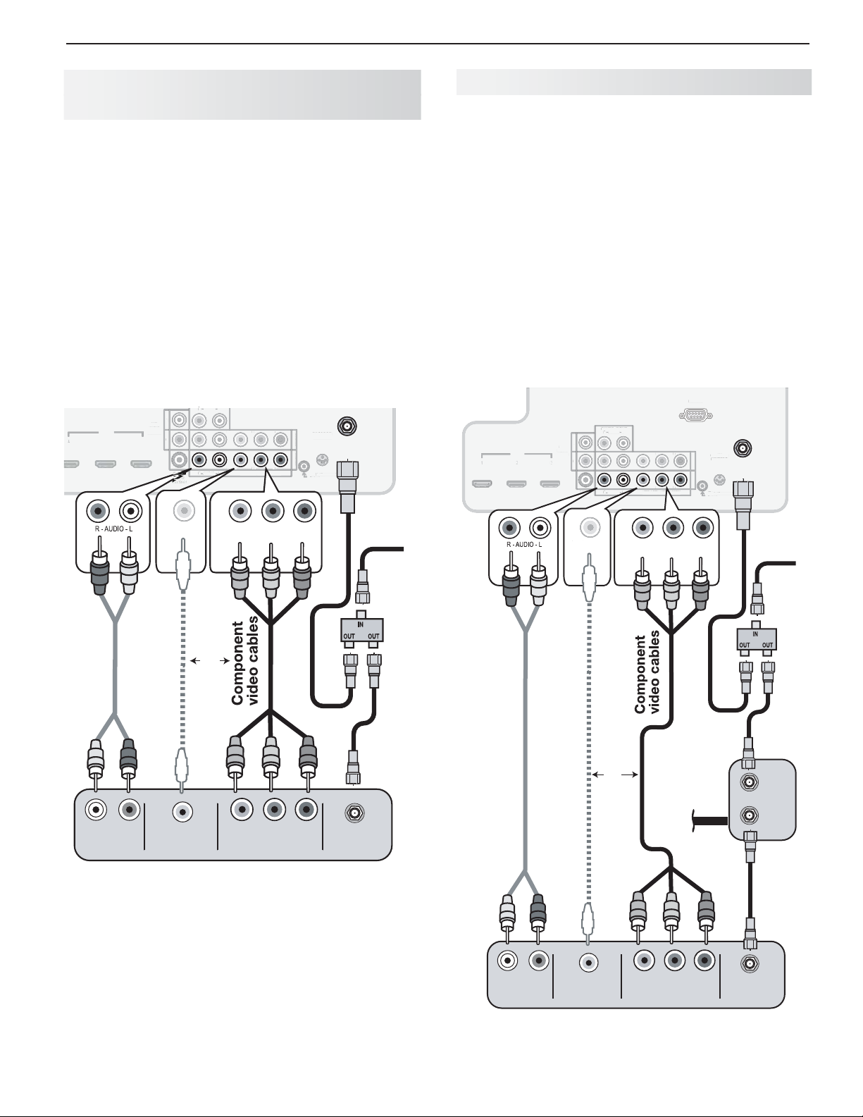
VCR or DVD Recorder to an
Antenna or Wall Outlet Cable
Required:
Two-way RF splitter
Two coaxial cables
Right and left analog audio cables
Component or composite video cables
Note:
• Use composite video only if component
video or HDMI are unavailable. For an
HDMI connection between the TV and
recorder, see page 17 .
• If your recording device has an analog-only
tuner, you must use a digital converter box
to enable recording of digital broadcasts.
R
L
AVR
AUDIO
AUDI
OUTPUT
HDMI
2
1
UTPU
R
3
Y/ VIDEOY/ VID
Y/ VIDEO
Y/ VIDE
Y/ VIDEO
Y/ VIDEO
L
R
AUDIO
AUDI
Y/ VIDEO
Pr
Pb
Pr
Pb
(480i / 480p / 720p / 1080i)
480i / 480p / 720p / 1080i
Pb
T
NP
INPUT 2
T 1
INPUT 1
INP
Pr
3D
3
GLASSES
EMITTER
IR-
NetCommand
-
Output
utpu
VC R or DVD Recorder to a Cable Box
Required:
Two-way RF splitter
Three coaxial cables
Right and left audio cables
Composite or component video cables
Video and audio cables required to connect the TV
to the cable box.
Notes: Use composite video if only if component video
or HDMI are unavailable. For an HDMI connection between the TV and recorder, see page 17 .
R
When using this connection confi guration, it is
possible to view live cable programs through the
recording device. For best picture quality always
view live cable programs directly from the TV input
connected to the cable box device.
TV main panel
AVR
VR
AUDIO
AUDI
HDMI
OUTPUT
INPUT
DVI/PC
AUDIO
AUDI
L
R
L
T
R
DIGITAL
ITAL
AUDIO
UDI
OUTPUT
Y/ VIDEOY/ VID
Y/ VIDEO
VID
Y/ VIDEO
Y/ VIDEO
L
R
(480i / 480p / 720p / 1080i)
480i / 480p / 720p / 1080i
AUDIO
UDI
T
Y/ VIDEO
RS-232C
ANT
ANT
ANT
3D
Pr
P
Pb
Pr
Pb
Pb
D
GLASSES
EMITTER
MITTE
INPUT 2
INPUT
T
INPUT 1
INP
R
IR-
NetCommand
-
utpu
Output
Pr
or
Audio
cables
Composite
video cable
L
R
AUDIO OUT
COMPOSITE
VIDEO OUT
DVD Recorder or VCR
COMPONENT
VIDEO OUT
ANTENNA
IN
RF Splitter
Audio
cables
L
R
AUDIO OUT
COMPOSITE
or
Composite
video cable
VIDEO OUT
DVD Recorder or VCR
Audio and
video from
cable box
directly to TV
COMPONENT
VIDEO OUT
Cable
Box
IN
OUT
ANTENNA
IN
RF Splitter
Page 20
20 2. TV Connections
HDMI
R
O
OUTPUT
P
b
Y/
O
r
P
b
P
r
2
U
L
O
O
T
C
A
O
(
)
(pp)
L
INPUT
A
O
Y/ VIDE
O
3D
GLASSES
R
T
RS-232C
NetCommand
O
t
INPUT
O
INPUT
R
O
O
T
b
O
P
r
b
P
r
U
2
DIG
L
A
O
OUTPUT
DVI/PC
O
(
)
(pp)
L
R
O
Y/ VIDE
O
3
GLASSES
R
ANT
IR
NetCommand
Output
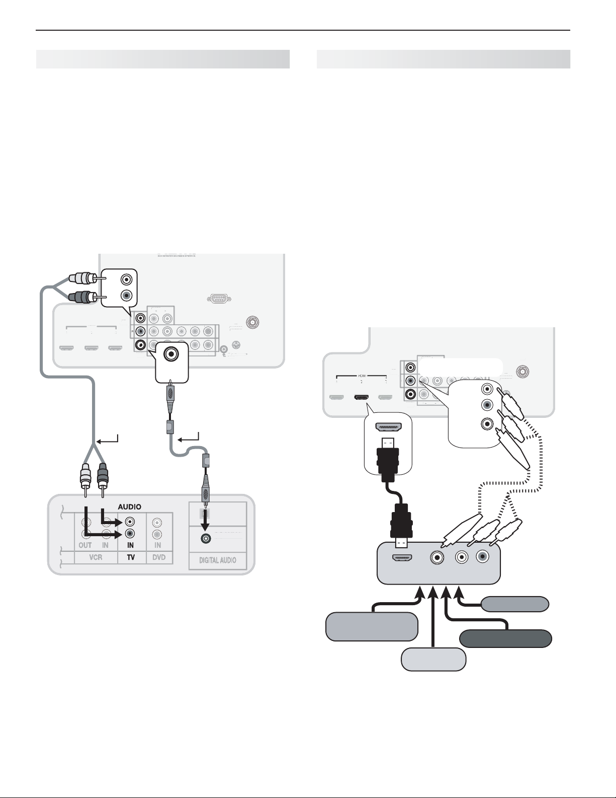
A/ V Receiver
Most setups require either a digital audio cable or
analog stereo audio cables. To send audio from TV
channels received on the
nected directly to the TV, you must use one of the
connections shown below. Usually, only one of these
connections is required.
The TV makes all audio available in digital and analog
formats:
Analog audio coming into the TV is available as •
output in digital stereo format on the
AUDIO OUTPUT
Digital incoming audio is available as analog output •
on the
AVR AUDIO OUTPUT L
L
AVR
AUDIO
OUTPUT
R
AVR
AV
AUDIO
AUDI
HDMI
OUTPUT
Stereo analog
cables
(for an analog
A/V receiver)
jack.
L
L
L
R
DIGITAL
DIGITA
DIGITAL
AUDI
AUDIO
AUDIO
UTPU
OUTPUT
OUTPUT
ANT
input or devices con-
and R jacks.
TV main panel
RS-232C
INPUT
DVI/PC
DVI/P
AUDIO
UDI
L
R
Pr
VIDE
Pb
Pb
(480i / 480p / 720p / 1080i)
480i / 480p / 720p / 1080i
P
INPUT 2
INPUT
T 1
INPUT 1
INP
Pr
Y/ VIDEO
Y/ VIDEO
L
R
AUDIO
UDI
DIGITAL
AUDIO
OUTPUT
Digital coaxial cable
(for a digital A/V
receiver)
DIGITAL
ANT
AN
3D
GLASSES
EMITTER
EMITTE
R
IR-
NetCommand
-
utpu
Output
A/ V Receiver with HDMI Output
Required: One HDMI-to-HDMI cable
This option allows you to view content from devices
connected to an A/V receiver. The A/V receiver can
send audio and video to the TV over a single HDMI
cable. You can use an HDMI connection as described
here in addition to an audio connection from the TV’s
audio output. The optional audio connection allows you
to hear, through the A/V receiver, devices connected to
the TV only, e.g., an antenna on the
You may be able to use the TV’s remote control (in
TV
mode) to operate connected CEC-enabled HDMI
devices. Experiment with your equipment to determine
which functions are available to the TV’s remote control.
See Appendix C , page 66 .
837 Series:
This setup allows you to use NetCommand-controlled audio and video switching over the
HDMI cable. See “Case 3: Automatic Audio and Video
Switching via HDMI” on page 54 .
INPUT
INPUT
DVI/PC
AUDIO
AUDI
L
L
R
L
L
AVR
AV
AUDIO
AUDI
OUTPUT
HDMI
2
1
UTPU
3
TV main panel
R
R
DIGITAL
ITA
DIGITAL
R
AUDIO
AUDI
UDI
AUDIO
AUDIO
OUTPUT
OUTPUT
Y/ VIDEO
Y/ VIDE
Y/ VIDEO
L
Optional analog or
ANT
input.
Pr
Pb
AVR
AUDIO
Pb
(480i / 480p / 720p / 1080i)
480i / 480p / 720p / 1080i
OUTPUT
GLASSES
T
EMITTER
EMITTE
INPUT 2
INP
L
INPUT 1
INPUT 1
Pr
IR-
NetCommand
-
R
Output
DIGITAL
AUDIO
OUTPUT
digital audio
connection
ANT
3D
D
R
A/V receiver back panel
Note:
On rare occasions, an HDMI signal may be •
copy-restricted and cannot be output from
the TV as a digital signal. To hear these copyprotected signals through the A/V receiver, use
the connection for an analog A/V receiver.
Check the A/V receiver’s Owner’s Guide for •
information concerning use of the digital input
and switching between digital sound and
analog stereo sound from the TV.
OPTICAL
PTICAL
INPUT
COAXIAL
COAXIAL
COAXIAL
INPUT
INPUT
A/V receiver
with HDMI
output
High-definition
DVD player
HDMI OUT
Cable box
DIGITAL
AUDIO
LR
VCR
DVD player
Page 21
Using TV Features
3
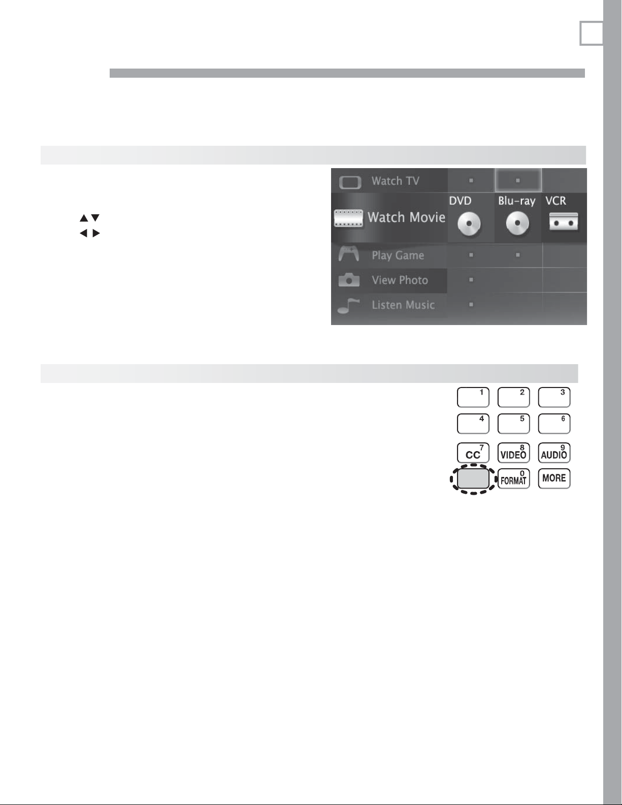
Selec ting an Input
The A ctivity menu lets you switch TV inputs. The inputs are
organized into groups based on possible ways to use them.
Press the
1.
Use
2.
Use
3.
Press
4.
To change the list of inputs shown in each activity group, •
see Inputs > Activity, page 40 .
To assign or change the names of input icons, use the •
Inputs > Name menu, page 40 .
ACTIVIT Y
to move through groups of TV inputs.
to select an input.
ENTER
key.
to switch to the input.
21
S leep Timer
The Sleep Timer turns the TV off after the length of time you set.
To set the TV to turn on at a certain time of day, see the Initial > Timer menu on page
38 .
Setting the Sleep Timer
Press
1.
2.
3.
Viewing or Changing the Sleep Timer
1.
2.
3.
MORE
on the remote control. The TV’s MORE menu will display.
Press
CANCEL
The maximum is 120 minutes.
Press
BACK
appear.
Press
MORE
Press
CANCEL (SLEEP).
Press
CANCEL
TV powers off.
(SLEEP) repeatedly to increase the time in 30-minute increments.
or wait five seconds without pressing any keys for the message to dis-
.
(SLEEP) additional times to change the number of minutes before the
SLEEP
With the MORE menu
displayed, press the
CANCEL key on the
remote control to
activate/deactivate the
Sleep feature.
Page 22
22 3. Using TV Features
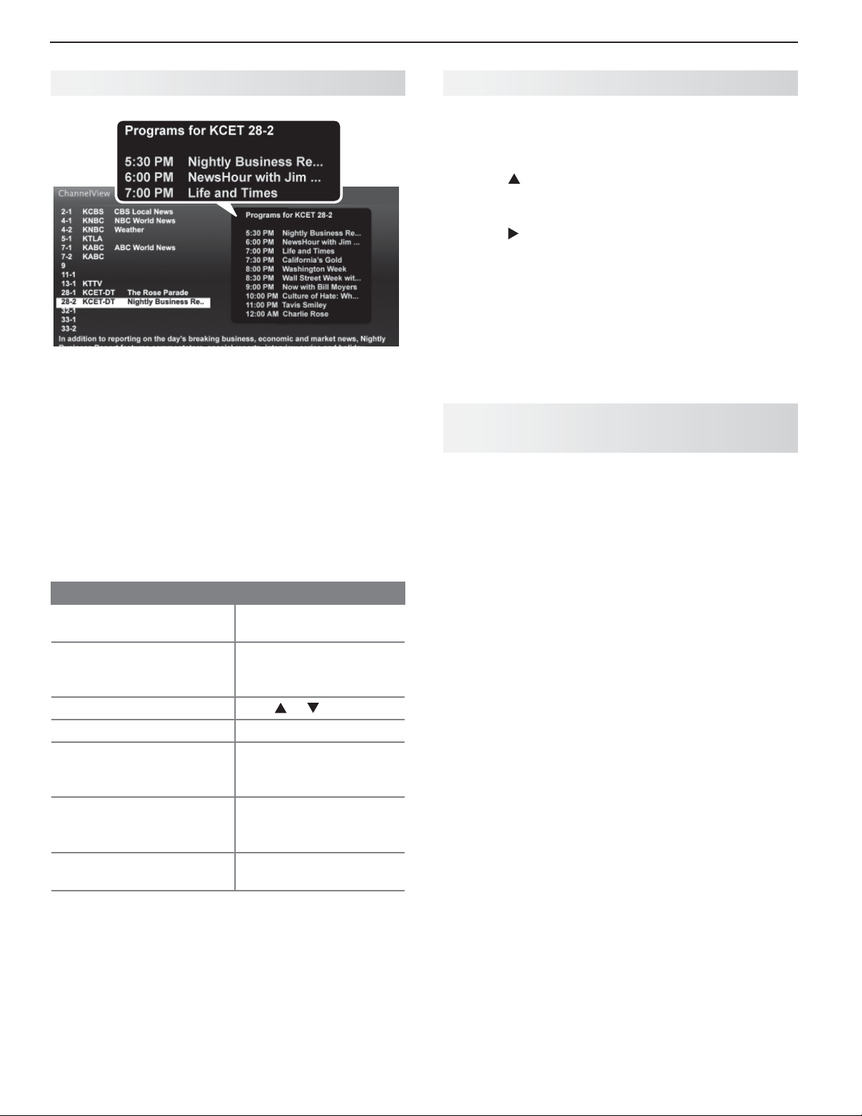
Ch annelView Channel Listings
ChannelView. Programs for the tuned channel are
listed on right side of screen.
ChannelView™ shows memorized channels on the
input. It displays channel names and program information for digital channels as sent by broadcasters or your
local cable service provider (information may be incomplete). No program information is displayed for analog
channels.
ANT
Redirecting Audio Output
Selecting an Audio Output Device
Press
1.
2.
3.
MORE
and then
Press
ers option will display only if there is a connection
on a TV audio output.
Press
phones, or TV.
to show the Speakers option. The Speak-
to select either AV Receiver, Head-
9
(AUDIO)
.
Disconnecting an Analog A/V Receiver
When you disconnect an analog A /V receiver, change
the Speakers setting to TV to hear sound from the TV
speakers. Change the setting using the remote control’s
MORE > 9
Speakers menu.
C ontrolling A/V Receiver Sound
(AUDIO )key or the Adjust > Audio >
Volume
Use one of the methods below to control sound volume from
an A/V receiver.
Note: You must set the TV Clock ( page 38 )
ChannelView listings for the current channel.
Using ChannelView
Feature Instructions
Receive updates for a
digital channel.
Display/hide ChannelView
listings from the ANT
input.
Scan channels one by one.
Scan channels quickly.
Jump to listings for a specific channel.
See more of the program
description for the current
channel (if available).
Tune to the highlighted
channel.
Tune to the channel.1.
Press the 2.
GUIDE
Hold or
Hold PAGE UP/PAGE DN
Enter the channel 1.
number.
Press 2.
ENTER
INFO
ENTER
t
o receive
INFO
key.
.
With a Standard TV Setup
Recommended Method:• Program the TV’s
remote control for your A/V receiver and enable the
Audio Lock feature. See page 60 .
Program the TV’s remote control for your A/V •
receiver and set the TV remote control’s mode to
AUDIO
. Return the control mode to TV to control the
TV.
Use the remote control that came with the A/V •
receiver.
With HDMI Control (CEC-Enabled HDMI
A/V Receiver)
The TV’s remote control may control some functions of
the A/V receiver. See Appendix C , “HDMI Control of
CEC Devices,” page 66 .
With NetCommand IR Control
837 Series. Set up NetCommand control of the A/V
receiver’s volume functions in the Inputs > AVR menu.
The TV’s remote will then control A/V receiver volume.
See page 52 .
Page 23
3. Using TV Features 23
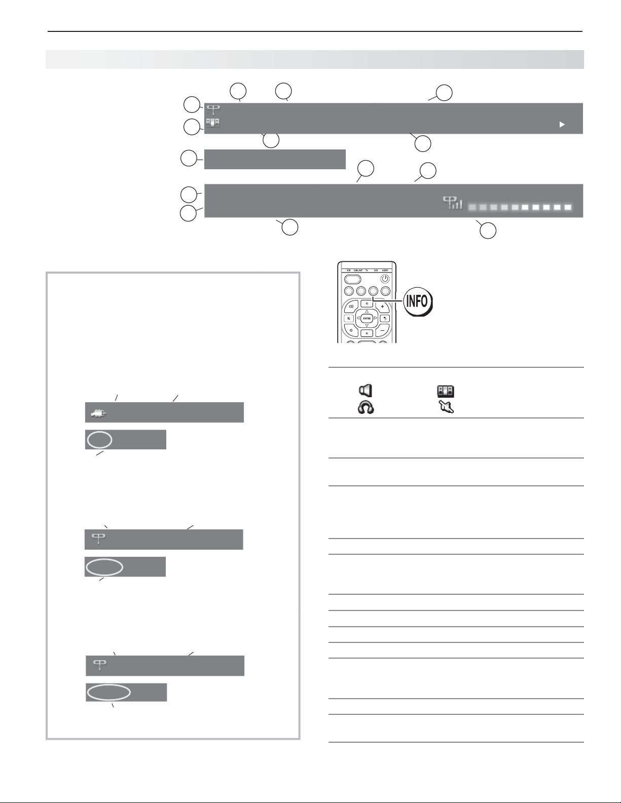
St atus Display
3
Press the
INFO
key to see
the on-screen status
display. The most
1
2
402-101 KABC Monday Night Football
TV-PG DLSV St. Louis vs. Tampa Bay, played in Tampa for
common displays are
shown here.
Sample information
from the on-screen
status display
8
Sleep 30 min
Tuesday 9:10 PM
9
HD 1080i Standard
10
About Channel Numbers
Channel Numbers for Over-the-Air Reception or
Reception by Direct Cable
Note: All signals are automatically converted to
1080p for display.
Standard-Definition Analog Channels
Cable Reception
Cable 3
480i Stretch
Receiving Standard-Definition
Analog Signal (480i)
Standard-Definition Digital Channels
Over-the-Air
Antenna
Reception
Ant 7-1 KABC-SD
SD 4:3 Stretch
Receiving Standard-Definition
Digital Signal (SD)
High-Definition Digital Channels
Over-the-Air
Antenna
Reception
Ant 7-1 KABC-HD
HD 16:9 Stretch
Receiving High-Definition
Digital Signal (HD)
Channel 3
Main Channel 7
Sub-Channel 1
Main Channel 7
Sub-Channel 1
4
5
12
6
7
13
Surround English
11
ACTIVITY
GUIDE MENU INFO BACK
14
1. Current Input
2. Audio Indicator. Key:
TV speakers External sound system
Headphones Mute
3. Channel number (antenna source only)
Digital channel includes major and sub-channel
numbers.
4. Digital channel name (if broadcast); antenna
source only.
5.
V-Chip rating
Antenna source only for digital signal•
Antenna or •
VIDEO
composite jack for
analog
signal
6. Program name (if broadcast); digital source only
7. Program description (if broadcast); digital
source,
antenna only. Press the
INFO
key additional
times to see more of the description.
8. Sleep Timer remaining time
9. Day and time
10. Signal type being received
11. Screen format in use
12. Program Audio indicator (antenna source only)
Digit•
al source: Stereo, Surround, Dual Mono
Anal•
og source:
Stereo, Stereo SAP, SAP
13. Available language (digital source, antenna only)
14. Signal-strength indicator (digital source,
antenna only)
Page 24
24 3. Using TV Features
TV Signals and Display Formats
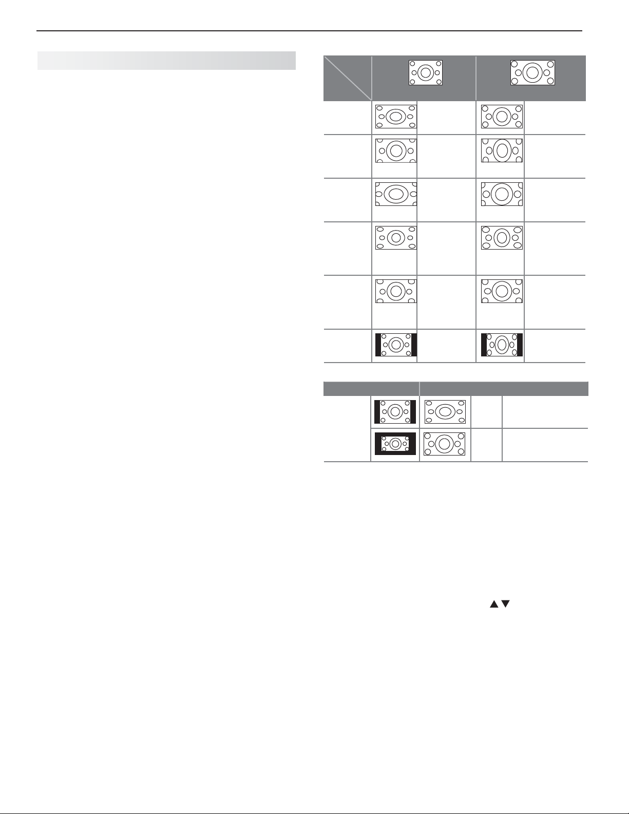
This is a 16:9 widescreen TV suitable for images available
from HDTV and many DVDs. You can view older-style, squarish images (4:3 aspect ratio) using one of the display formats
described on this page. Press the
0 key (
FORMAT
) to cycle through available display formats.
The TV remembers the format you last used for each input.
DVD Image Definitions
Image information may be stated on the DVD case. Some
DVDs support both of the formats described below.
Anamorphic (or Enhanced for WideScreen TV)
Indicates DVDs recorded to show widescreen images properly on 16:9 TV sets using the TV’s Standard format mode
(recommended)
.
Non-Anamorphic (or 4:3, 1.33:1, Letter Box, or
Full Screen)
Indicates DVDs recorded for viewing on squarish TV
screens. They may be full screen (4:3 or 1.33:1) which
crops movies to fit the narrow TV, or letter box, which
adds black top and bottom bars.
Signal Definitions
480i: Older type of interlaced signals from the
composite
VIDEO
, component
480p: Progressive-scan DVD signals on component
Pr
or
HDMI
jacks.
720p and 1080i: High-definition signals received through
component
Y Pb Pr
or
HDMI
always 16:9 (widescreen).
1080p: High-definition signals from a PC or Blu-ray player,
HDMI inputs only.
SD 4:3: Standard-definition squarish-screen-format
signals from digital channels on the
SD 16:9: Standard-definition widescreen-format signals
from digital channels on the
HD 16:9: High-definition 16:9 widescreen signals from
digital channels on the
ANT
TV Display Format Definitions
Standard: The full-screen format used by HDTV signals.
Use this format to display anamorphic DVDs with a 1.78:1 or
1.85:1 aspect ratio. Anamorphic DVDs with a 2.35:1 aspect
ratio are displayed correctly but with top and bottom black
bars. Squarish (4:3) images are stretched evenly from side to
side. Available for all signals.
Expand: Enlarges the picture to fill the screen by cropping
the top and bottom; useful for reducing the letter box top and
bottom bars of non-anamorphic DVD images.
Zoom: Enlarges the picture to fill the screen by cropping the
sides, top, and bottom to eliminate black bars.
480i/480p and SD 4:3 signals:• Eliminates top and bottom
bars on anamorphic DVDs with a 2.35:1 aspect ratio.
720p, 1080i, SD 16:9, and HD signals:• Eliminates bars
added to squarish 4:3 images.
MORE
key and then the
ANT
Y Pb Pr
, or
HDMI
jacks.
jacks. These signals are
ANT
input.
ANT
input.
input.
input,
Y Pb
Original
Signal
TV
Display
Standard
Expand
Zoom
Stretch
Stretch
Plus
Narrow
Non-anamorphic or SD 4:3
Distorted.
Not recommended.
Recommended for
letterbox. See
Note 1.
Distorted.
Not recommended. See
Note 1.
Recommended for
standard
broadcasts.
See Note 1.
Recommended for
standard
broadcasts.
See Note 1.
See Note 1 Distorted; not
Anamorphic DVD
Recommended
Distorted; not
recommended.
See Note 1.
Recommended
for anamorphic
2.35:1 images.
See Note 1.
Distorted; not
recommended.
See Note 1.
Distorted; not
recommended.
See Note 1.
recommended.
See Note 1.
Note 1: Available for 480i, 480p, and digital SD 4:3 signals only.
Original Signal Display Formats
SD 16:9 or
HD Digital
720p, 1080i,
1080p Signal
TV Display Formats. Press the
repeatedly press the 0
key (
available for the current program. Press the
Wide
Expand
Zoom
Recommended to remove side bars.
Recommended to remove bars from the top,
bottom, and sides.
MORE
key and then
FORMAT) to see the displays
INFO
key to see
the name of the display format in use.
Stretch: Stretches a squarish 4:3 image across the
screen to display the entire image with less distortion
than the Standard format.
Stretch Plus:
Similar to Stretch, but minimizes distortion on the sides by expanding the picture to crop off
portions of the top and bottom. Use to adjust the
vertical position of the picture.
Narrow: Displays narrow 4:3 images in their original
shape. Adds black side bars to fill the screen.
Wide Expand: Enlarges the picture, cropping the image
on both sides. Removes or reduces black side bars added
to narrow images converted to 16:9 signals for digital
broadcast.
Note: All high-definition channels send widescreen
(16:9) signals, but not all programming was created for
the widescreen format. The broadcaster may stretch
the image or add side bars to fill the widescreen area.
Page 25
3. Using TV Features 25
3D
GLASSES
EMITTER
3 D Video
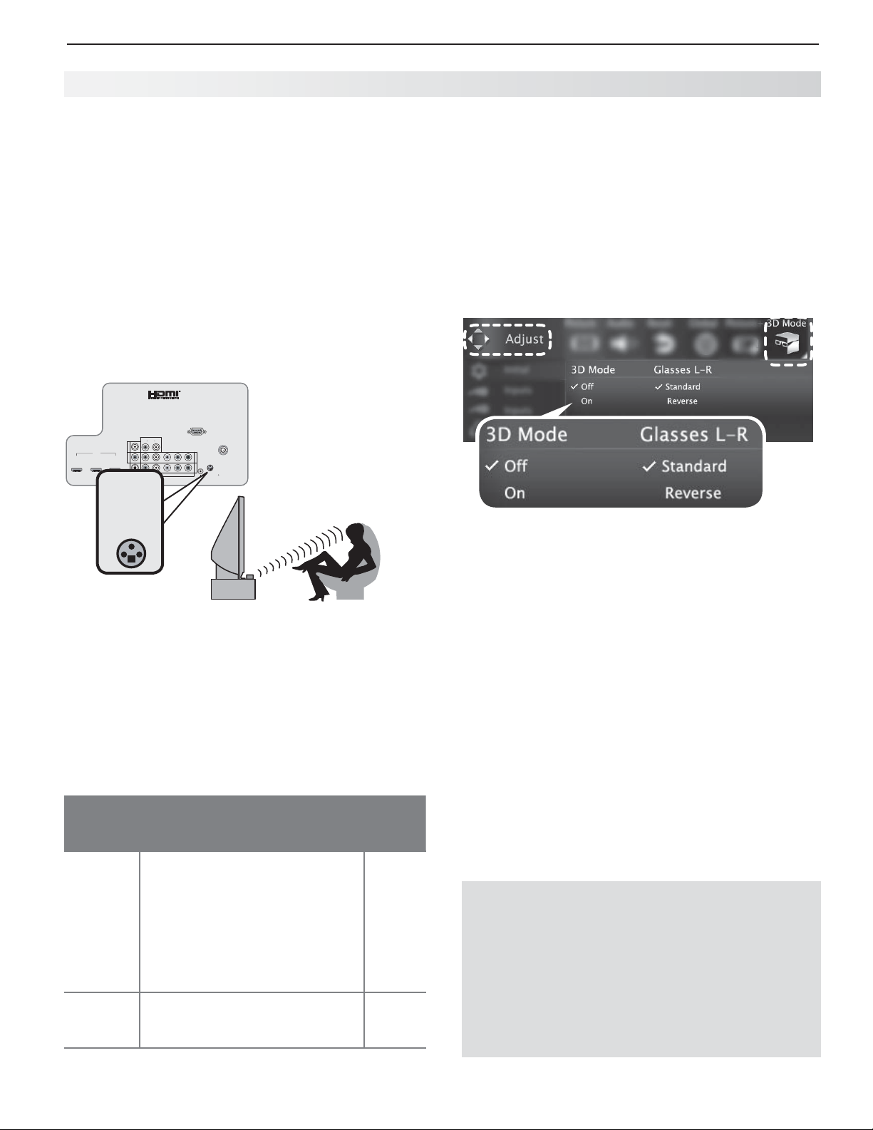
This section provides Instructions for viewing 3D
video using 3D glasses and the TV’s 3D feature. The
3D options are found in the Adjust > 3D Mode menu
described on page 34 .
Initial Setup
Check if your HDMI 3D video source device outputs
1.
a 1080p 60 Hz signal. This information will be
needed when you assign an input name in the New
Device Found screen.
If your 3D glasses came with an emitter box,
2.
connect the emitter box to the
EMITTER
jack. Place the box in front of the TV
where there is an unobstructed path to the glasses.
RS-232C
INPUT
DVI/PC
AUDIO
L
R
L
AVR
AUDIO
Y/ VIDEO
OUTPUT
HDMI
R
2
1
3
Pb
Y/ VIDEO
Pb
L
DIGITAL
R
(480i / 480p / 720p / 1080i)
AUDIO
AUDIO
OUTPUT
ANT
3D
Pr
GLASSES
EMITTER
INPUT 2
INPUT 1
Pr
R
IR-
NetCommand
Output
3D GLASSES
Watching 3D Video
Note: 3D glasses are required.
Press
1.
2.
3.
4.
Use the Adjust > 3D Mode menu to enable 3D video.
ACTIVIT Y
.
Highlight the icon for the 3D video device and press
ENTER
.
Press
MENU
and select the Adjust > 3D Mode
menu.
Select
On. The On setting will be memorized for
the current input when you exit this menu.
Power on the TV and the source device.
3.
Connect the source device to the TV’s HDMI input.
4.
When the
5.
New Device Found screen displays,
name the input according to the table below.
The signal type and choice of name are important
because the TV will process the video signal
differently depending on the name you assign.
If your source device is a Blu-ray disc or game
console, the signal must be 1080p at 60 Hz.
Source
of 3D
3D Video Signal
Video
Computer Recommended: 1080p 60 Hz
(1920 X 1080). The image will fill
the TV screen.
Other 60-Hz computer video
signals compatible with the TV
will display with black bars. See
“Computer Display Formats” on
page 27 .
Any other
3D video
To see 3D video, the signal must
be 1080p 60 Hz
source
Press
6.
BACK
to close the New Device Found screen.
Assign
Name
PC
Any
other
name
Press
5.
6.
BACK
to close the menu.
If the image does not appear correct
appear to be moving in instead of out),
(e.g., objects
open the
Adjust > 3D Mode menu and set Glasses L-R to
Reverse.
To Watch Regular (non-3D) Video
The 3D Mode setting is memorized for each input.
When you want to watch non-3D video on the input
selected above, open the Adjust > 3D Mode menu and
set 3D Mode to Off.
Important Note About 3D Images
To display 3D images, Mitsubishi Home Theater DLP
TVs require that source devices support checkerboard display formats for 3D gaming or 3D cinema
content. A 3D standard format does not currently
exist for Blu-ray or DVD prepackaged media. Future
3D standards may be incompatible with Mitsubishi
Home Theater DLP TVs. Please visit mitsubishi-tv.
com for updates and information.
Page 26
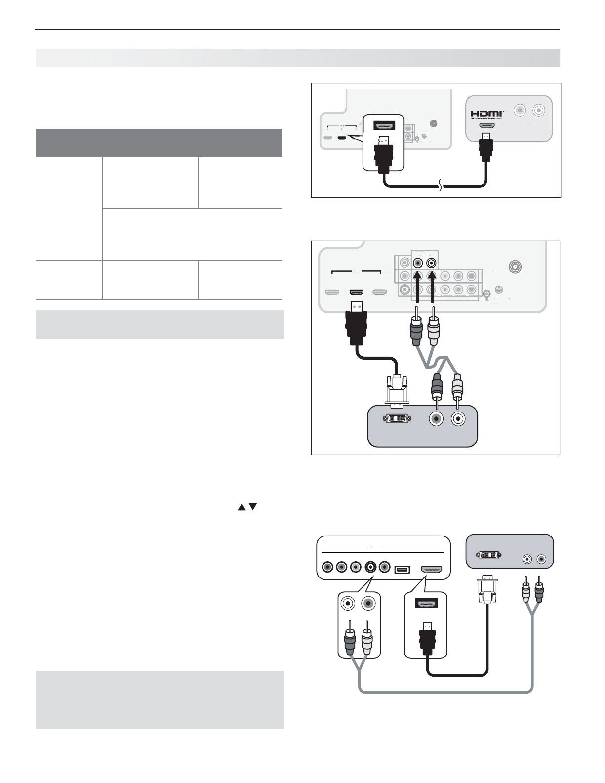
26 3. Using TV Features
P
r
2
)
)
3D
S
IR
NetCommand
Outp
O
R
L
2
3
O
O
T
P
bY/
O
P
r
P
b
U
2
U
1
L
AUDIO
O
T
DVI/PC
O
(
)
(pp)
R
L
UT
O
Y/ VIDE
O
3
GLASSES
NetCommand
O
t
R
Using the TV with a Pe rsonal Computer
Connecting a Computer to the TV
Use one of the connection methods listed below based
on your computer’s video output.
Computer
Video Output
Video Connection
Digital DVI DVI-to-HDMI cable
or an HDMI cable
with an HDMI-toDVI adapter
Note: If the computer’s audio output
is a single mini jack, a mini audio-toRCA-male “Y” adapter cable is also
required.
HDMI HDMI-to-HDMI
cable
IMPORTANT
This TV accepts digital computer signals only.
Connect the computer’s digital signal output to one
1.
of the TV’s
HDMI
jacks. See the connection dia-
grams for the method suited to your equipment.
Connect the computer’s audio output using one of
2.
these options:
• For digital DVI signals, connect analog left/right
audio to the TV’s
DVI/PC INPUT AUDIO
• For HDMI signals, no additional audio connection is required.
Power on the TV and computer. The TV will detect
3.
the connection and display the New Device Found
screen.
In the
4.
New Device Found screen, press to
highlight PC in the list of device types. It is important to use the name PC so that the TV processes
the video signal correctly.
Press
5.
BACK
to close the New Device Found screen.
Audio
Connection
Stereo audio
cables
No additional
audio connection is required.
jacks.
TV main
panel
INPUT
Y/ VIDEO
HDMI
2
1
3
Pb
Y/ VIDEO
Pb
L
(480i / 480p / 720p / 1080i)
OUTPUT
ANT
3D
Pr
GLASSE
GLASSES
EMITTER
INPUT 2
INPUT 1
INPUT 1
Pr
R
1080i
IR-
NetCommand
-
ut
Output
R L
AUDIO
AUDI
Computer
with HDMI
audio and
video output
An HDMI-to-HDMI connection carries all video and
audio on a single cable.
INPUT
INPUT
INPUT
INP
DVI/PC
DVI/PC
DVI/PC
AUDIO
AUDI
AUDIO
AUDIO
L
L
L
R
R
R
L
AVR
AUDI
AUDIO
OUTPUT
HDMI
HDMI
HDMI
2
2
2
1
1
1
UTPU
R
3
3
3
DIGITAL
DIGITA
AUDIO
OUTPUT
UTPU
Y/ VIDEO
Y/ VIDEO
L
R
AUDIO
AUDI
VIDE
Pb
Pb
(480i / 480p / 720p / 1080i)
480i / 480p / 720p / 1080i
Pr
T
NP
INPUT 2
T
NP
INPUT 1
Pr
3D
GLASSES
EMITTER
EMITTER
IR-
NetCommand
IR-
utpu
Output
ANT
ANT
D
R
TV main panel
1.
1.
2.
2.
Computer with
DVI OUT
RL
AUDIO
DVI and stereo
audio outputs
A DVI connection from a personal computer requires a
separate audio connection. A computer connected to
the TV main connector panel is shown above.
Computer with DVI and
TV convenience inputs
INPUT 3
LR
Pb
Y/ VIDEO
Pr
AUDIO
USB HDMI 4
stereo audio outputs
DVI OUT
AUDIO
RL
Note: If your computer provides digital audio out-
put (coaxial or optical), you can connect it
directly to a digital A/V receiver and bypass
the TV.
HDMI 4
HDMI-to-DVI cable
837 Series: Computer with DVI output connected to
the convenience panel.
Page 27
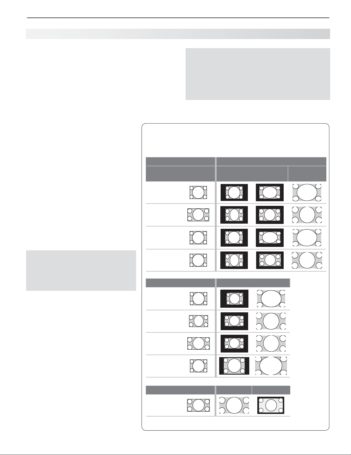
3. Using TV Features 27
Using the TV with a Personal Computer
Co mputer Video Adjustments
Power on the computer.
1.
Select
2.
press
highlight to the PC icon, and press
Working from the computer, change the resolution
3.
of the computer image. View the computer image
on the TV and maximize the computer resolution
while maintaining a suitable aspect ratio for the
image.
Perform TV video adjustments.
4.
MORE
to access video-adjustment options.
The following additional adjustments
are available for computer video:
Horiz Position (Horizontal Position).
Manually adjust the horizontal
position.
Vert Position (Vertical Position).
Manually adjust the vertical position.
Press
5.
repeatedly to find the picture format
(aspect ratio) best suited to the image.
See the chart on this page showing
how different computer resolutions
can be displayed on the TV.
PC from the Activity menu. To do this,
ACTIVIT Y
then press 8 (VIDEO) repeatedly
MORE
to open the Activity menu, move the
ENTER.
Press
then press 0 (FORMAT)
Tip
Set the computer’s screen saver to display a pattern
after several minutes of inactivity. This acts as a
reminder that the TV is powered on and the lamp
is in use. The lamp is in use whenever the TV is
powered on, even if the screen appears dark.
C omputer Display Formats
Press
MORE
then press 0 (FORMAT) repeatedly to cycle through the
TV displays available for your computer’s video signal.
Computer Signal
Original Format
VGA
640 X 480
WVGA
848 X 480
SVGA
800 X 600
As Displayed on TV Screen
4 X 3
Standard
16 X 9
Standard
Zoom
Distortion in Computer Images
Computer images may show distortion
when viewed on the TV, e.g., lines that
should be straight may appear slightly
curved.
Image Resolution
Your Mitsubishi TV can display the resolutions shown in the chart from standard
VGA (640 x 480) through 1920 x 1080
signals at a refresh rate of 60 Hz. The
resolution of 1920 x 1080 is supported at
refresh rates of 24, 30, and 60 Hz.
In most cases, the computer will select
the best resolution match to display on
the TV. You can override this setting if you
wish. Refer to your computer operating
system’s instructions for information on
changing the screen resolution.
You may need to restart the computer for
changes to take effect.
WSVGA
1064 X 600
Original Format Standard Zoom
XGA
1024 X 768
PC 720p
1280 X 720
WXGA
1360 X 768
SXGA
1280 X 1024
Original Format Standard Reduce
PC 1080p
1920 X 1080
Page 28
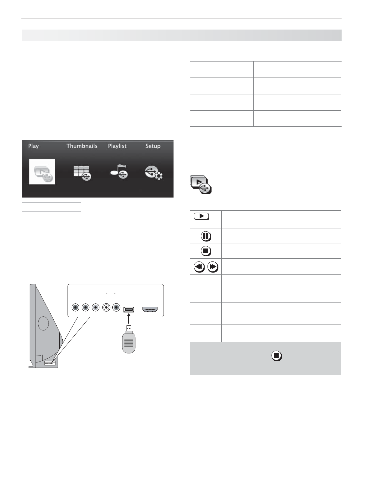
28 3. Using TV Features
USB HDMI 4
INPUT 3
AUDIO
LR
Pb
Y/ VIDEO
Pr
Camera Images and M usic Files
837 Series TVs Only
The TV can read photo or music files from a USB •
device. Photos must be in JPEG format and music
files must be in mp3 or wma formats. To play
music files while displaying a photo slide show, see
“USB Media Setup Menu” on the opposite page .
The TV can display files of still or moving images •
from a camera through the
Y/V I D EO
The USB Media Player Menu
port.
To use the USB Media Player menu:
3.
Activate any of the
menu options
Display the Activity
menu.
Display the main
menu.
Display status for the
file source.
To resume use of the USB port after switching the
4.
TV to a different input, press
Highlight an icon and press
ENTER
.
Press
ACTIVIT Y.
Press again to
clear.
Press
MENU.
Press again to
clear.
Press
INFO.
Press
BACK
clear.
ACTIVIT Y
, choose View
Photos, and select the USB port.
to
Displaying the Menu
Back up the data on your USB drive before con-
1.
necting it to the TV. Mitsubishi is not responsible
for any file damage or data loss.
Connect your USB card reader or USB drive to the
2.
TV’s USB port.
The USB Media Player menu displays while files
are being read. Wait until icons appear in the menu
before continuing.
837 series TVs can read photo and
music files from the USB port.
Playing a Slide Show or Playlist
Use these keys while playing a slide show or playlist.
Replays the slide show or playlist.
or
ENTER
Pauses a slide show or playlist.
Stops a slide show or playlist.
Displays the previous or next slide.
GUIDE
BACK
MENU
ACTIVIT Y
INFO
Always stop playback with
to a different TV input before disconnecting your
USB device.
Rotates an image clockwise in 90˚ increments.
Displays the USB Media Player menu.
Displays the main menu.
Displays the Activity menu.
Displays slide name or track name. Press
BACK
to clear.
IMPORTANT
(
STOP
) or change
Page 29
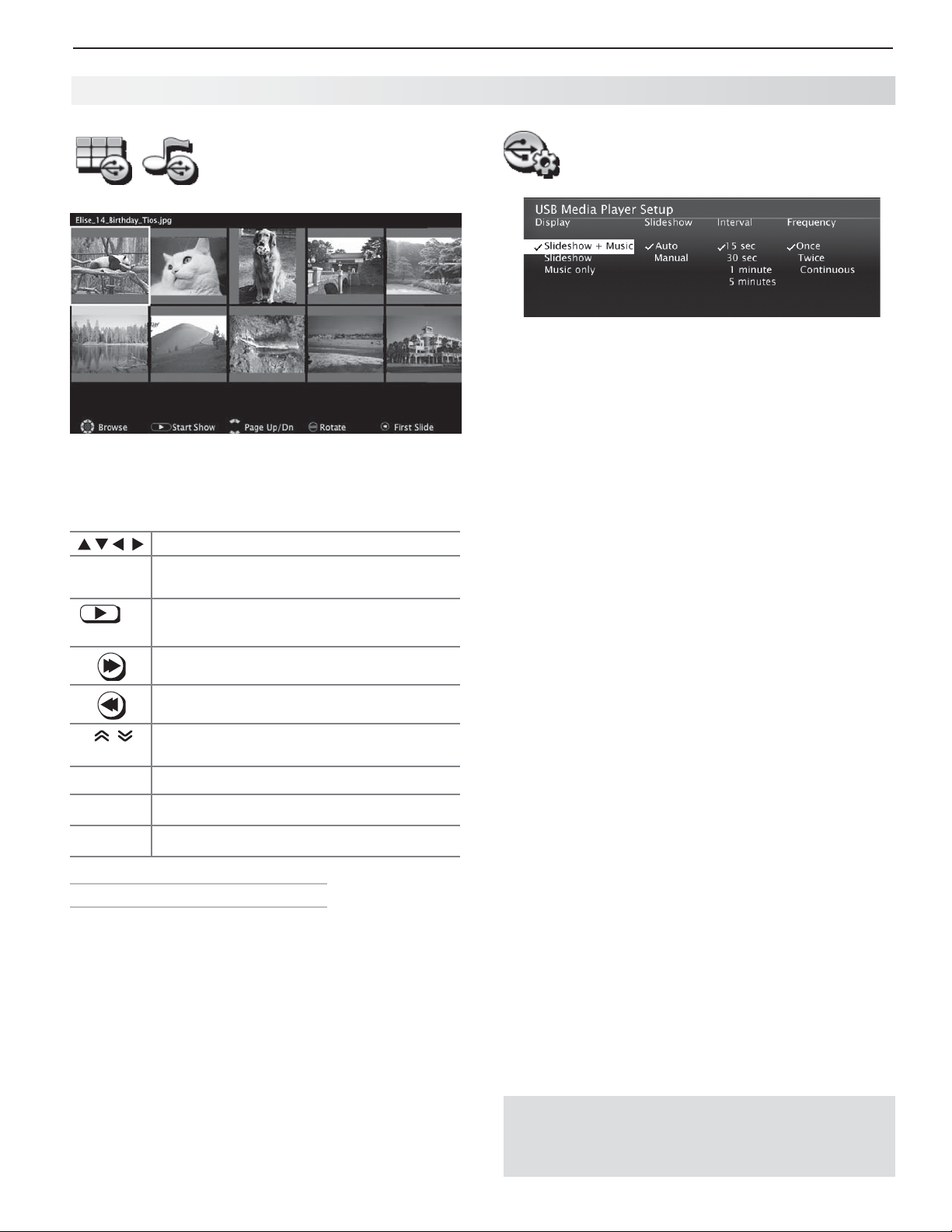
3. Using TV Features 29
Camera Images and Music Files, continued
Thumbnail and Playlist
Menus
JPEG Thumbnail Menu
Use these keys while viewing JPEG thumbnail images
or the music tracks in a playlist.
GUIDE
ENTER
Moves the highlight from item to item.
Rotates a thumbnail clockwise in 90˚
increments
Plays the slide show or playlist starting
or
with the highlighted item.
Selects the last item on the current page.
Selects the first item on the current page.
Use the USB Media Setup menu set up play of a slide
show or playlist.
• If JPEG image files and wma/mp3 files are on the
U SB Media Setup Menu
USB device, choose:
Slideshow + Music Slideshow Music only -
Slideshow.• Select either Auto or Manual advance
for the slide show. During manual operation, press
ENTER
to advance to the next slide.
Interval.• For automatic advance, select the time
interval for display of each slide. The interval you
select here is the minimum time between slides;
actual time may be longer for larger files.
Frequency.•
number of times (frequency) to play the complete slide
show and/or playlist:
Press •
BACK
return to the Media Player menu.
For automatic advance, select the
Once, Twi c e, or Continuous.
to close the Media Setup menu and
PAGE UP/DN
BACK
MENU
ACTIVIT Y
USB Port Compatible Picture Files
• Still images recorded on digital cameras using the
Exchangeable Image File Format, version 2.1 (EXIF
2.1) standard for digital still cameras and Design
Rules for Camera File Systems version 1.0 (DCF 1.0)
• Some images opened and resaved on a computer
may not play back or may not display in the thumbnail list. This happens if the files were resaved in an
incompatible format.
• Full path file names can be no longer than 50 characters and must end in a .jpg extension. Only the
first 20 of the 50 characters will display.
• Images on storage devices with a capacity of over
256 MB can take a longer initial time to display.
Displays the next or previous page of
items.
Displays the USB Media Player menu.
Displays the main menu.
Displays the Activity menu.
Notes on Using the USB Port
• The TV ignores all commands while reading files.
for icons to appear in the USB Media Player menu
before continuing.
• Large files or high-capacity storage devices may take a
long time to display. The screen will be blank while files
are read.
• Use only one source device at a time.
• Back up the data on your USB drive before connecting it to the TV. Mitsubishi is not responsible for any
file damage or data loss.
Note:
The TV can read JPEG files as created by the
camera. If you edit a picture file on a computer
and resave the image, the TV may be unable to
read the resaved file.
Some manufacturers’ devices may be incompatible with the TV. If the TV is unable to display your
photos, you can:
• Transfer
• Use your digital camera’s composite video
output. See page 30 .
files to a different USB device.
Wait
Page 30
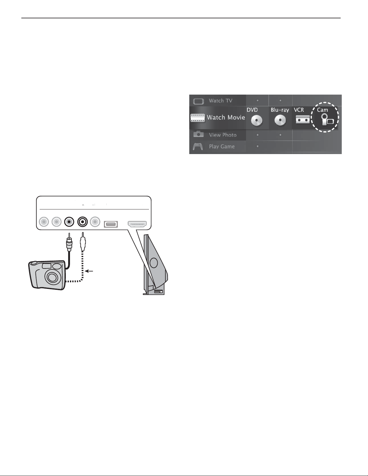
30 3. Using TV Features
US
H
4
INPUT 3
O
LRP
b
Y/
O
P
r
Phot os and Moving Video
as Composite Video
Connect the camera to the TV using a composite video
cable if:
• You are unable to see images using the USB port.
•
You wish to view moving video from the camera.
Control the slide show or movie through the camera as
the TV’s USB Media Player menu will be unavailable.
The display resolution will be standard-definition (480i).
Refer to the owner’s manual supplied with the
1.
camera for instructions needed for this setup.
Set the camera’s output signal type to
2.
put the camera into playback mode.
With the camera still turned on, connect your digital
3.
camera’s composite video cable (usually yellow) to
the TV’s
camera’s audio output cable to the
Pr
Y/V I D EO
INPUT 3
Pb
Y/ VIDEO
VIDE
Y/ VIDEO
jack. To hear audio, connect the
LR
L
AUDIO
AUDI
AUDIO
USB HDMI 4
B
NTSC and
AUDIO L
DMI
jack.
4.
When the
New Device Found screen displays,
assign the name Camcorder.
5.
6.
7.
BACK
Press
Press
press
to close the New Device Found screen.
ACTIVIT Y,
ENTER
select Watch Movie > Cam, and
.
If viewing photos, advance through the images
manually or set the camera to advance automatically.
Optional
Audio Cable
Camera connection using a composite video cable
Page 31
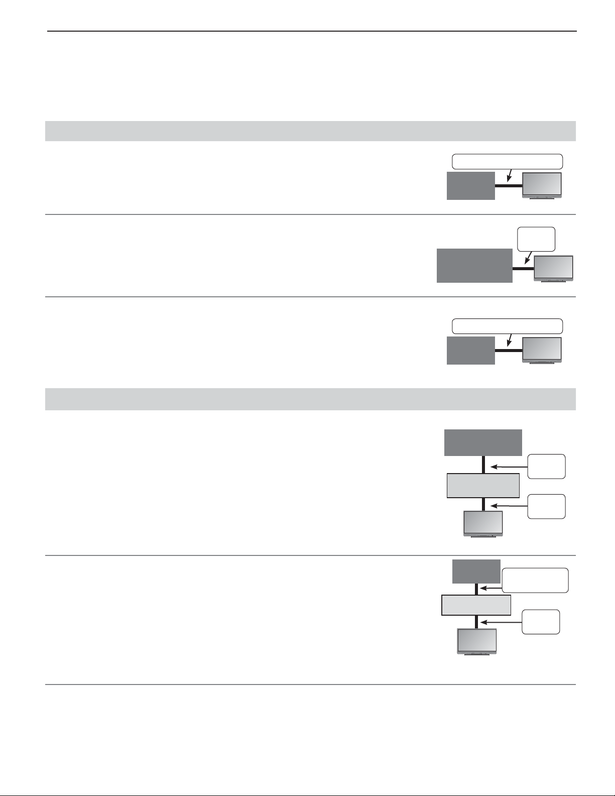
3. Using TV Features 31
Introduction to H ome-Theater Control
This TV offers a choice on home-theater-control systems. This summary offers some examples of the control
methods available using the TV’s remote control. You may wish to use one or more of these methods in your
home theater after completing Auto Input Sensing.
Source device connected directly to the TV
Remote Control Programming (Any Connection Type)
Program the remote control to operate the A/V device. To control the device, set
the remote control to the correct mode for the device type. See Appendix B , “ Programming the Remote Control .” In the case of an A/V receiver, use the Audio Lock
Any Connection Type
A/V
Device
feature, page 60 .
C EC-Enabled HDMI Device (HDMI Connection Only)
See Appendix C , “HDMI Control of CEC Devices,” page 66 .
837 Series: NetCommand IR Control (Any Connection Type)
Set up Net Command IR control of the device’s keys as desired. See “IR Emitter
Placement,” page 46 , and “Initial NetCommand Setup,” page 47 .
CEC-Enabled
A/V Device
Any Connection Type
A/V
Device
Source device connected to an A/V receiver connected to the TV
CEC-Enabled
Source Device
CEC-Enabled HDMI A/V Receiver
The TV’s remote control may operate some functions of a connected A/V device.
You can switch to the device by selecting its icon in the TV’s Activity menu. See
Appendix C , “HDMI Control of CEC Devices,” page 66 .
A/V Receiver
TV
HDMI
Cable
TV
TV
HDMI
Cable
HDMI
Cable
TV
837 Series: A/V Receiver with HDMI Output (no CEC)
Set up Net Command IR control of the 1. A / V receiver’s keys as desired. See “IR
Emitter Placement,” page 46 , and “Setting Up A/V Receiver Control,” page 52 .
Set up Net Command IR control of the 2. source device’s keys as desired. See
“NetCommand Control of a Device Connected to an HDMI A/V Receiver,” page
55 .
Source
Device
A/V Receiver
TV
Any Con-
nection Type
HDMI
Cable
Page 32
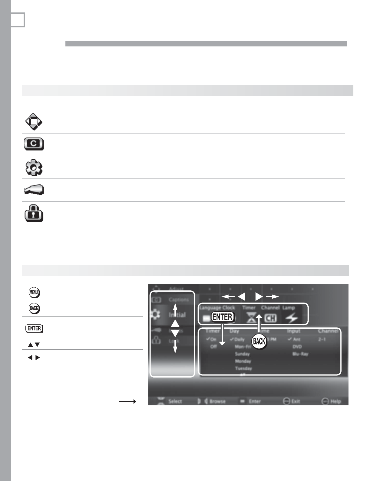
32
4
Ma in Menu
Press
MENU
TV Menus
on the remote control to open the main menu and then select from one of these categories.
Adjust
Captions
Initial
Input
Lock
Menu Navigation
Displays or clears the main menu.
Customize picture and sound settings. 33
Turn closed captions on and off; customize caption displays. 37
Perform basic TV setup. Set language, scan (memorize) channels and edit
channel options, set the TV clock, set Lamp Mode, set auto-on TV Timer.
Assign names to TV inputs, enable HDMI Control, assign activities to inputs.
837 Series. Perform Net Command IR “learning.”
Restrict TV use. Disable the control-panel buttons. Set a pass code. 42
38
40
Moves up one menu level.•
Clears the current menu.•
Moves navigation into options •
area.
Selects an item.•
Moves the highlight within menus.
Makes adjustments in some
menus.
Look for the key guide at
the bottom of each menu.
Page 33
4. TV Menus 33
A djust
Picture
Audio
Reset
Gl obal Video Mute
See page 35 for picture adjustments.
See page 36 for audio adjustments.
Resets audio and picture adjustments for the current input. Highlight the • Reset icon and press
ENTER
twice
Reset• has no effect on settings for Balance, Listen To, Language, Film Mode, and Advanced
Picture.
(non-antenna
inputs only)
Audio
Screensaver
.
On Displays a solid colored background when there is no video signal
from the current input. The colored screen reminds you that the
TV is powered on when there is no picture. The TV will power off
after five minutes without receiving a video signal.
Off The screen appears black when there is no video signal from the
current input.
On, Off Select On to display a random pattern while playing an audio-only
input. To use this feature, the input must be either
Named • CD or MP3 Player and selected under the Listen
Music activity.
or
Be the •
ANT
input.
Film Mode
(480i and 1080i
signals only)
Smooth 120Hz Off, On
Blue Glow
(837 series)
Te st P i ct u re
Auto, Off
On, Off Select On to see blue accent lighting when the TV is powered on.
Displays a test picture for use by TV servicers.
Note: When playing an audio-only input, the TV will power off
after 12 hours of inactivity.
In
Auto
, the TV automatically detects and applies film-decoding correction to movies filmed at 24 frames per second. Try the
if images show many jagged edges.
When On, Smooth 120Hz™ reduces motion blur in action scenes but
may show pixel structure during slower motion or in still images.
Off
setting
Page 34
34 4. TV Menus
Adjust, continued
P icture+
PerfectColor Sliders
PerfectColor
Using PerfectColor:
Highlight the PerfectColor™ icon and press
retained independently for each TV input.
Using PerfecTint (837 Series):
• To switch between PerfectColor™ and PerfecTint™ adjustments, highlight Adjust Mode and
press
.
• Press to move from one color bar to the next.
• Press to change settings.
• Press
• Press
CANCEL
MENU
to return to the main menu.
Adv anced
Picture
Press 1.
MENU
. Under Picture+, highlight the Advanced Picture icon and press
With 2. Picture Mode highlighted, press
837 Series: Choose
Use 3.
to
Press 4.
Use 5.
Press 6.
current input.
to change settings.
to
MENU
to close the menu
PerfectTint Sliders
(837 series)
ENTER
to restore default settings.
Advanced Picture allows you to save highly customized picture adjustments
for each input. Mitsubishi recommends a professional installer make
these adjustments.
ENTER
ADV1
(daytime settings) or
highlight an option you wish to change and press ENTER
navigate through the screen to additional options and press
. The
Advanced Picture adjustments will be in effect for the
Adjusts the saturation (intensity) of six colors for
the current image source.
Adjusts six hues for the current image source
to display the PerfectColor menu. Settings are
ENTER
.
to change
ADV2 (nighttime settings)
from blank (undefined)
.
to change settings
to
ADV
.
.
3 D Mode
To use the custom Picture Mode at a later time
Press
MENU
and go to Adjust > Picture > Picture Mode and:
737 and C9 Series 837 Series
Select •
SPECIAL if settings were saved by
your professional installer.
Otherwise select • ADV.
To return to the default values for Advanced Picture
Display the Picture+ > Advanced Picture menu and:
737 and C9 Series 837 Series
Highlight RESET Pic Mode and press
3D Mode
Glasses L-R Standard,
On, Off
Reverse
ENTER
.
Use the On setting for video games and movies that require 3-D
glasses. This setting applies only to the current input.
Note: 3D options are available only for 1080p 60-Hz video
sources connected to an HDMI input.
Synchronizes the 3D glasses with the image on screen to provide
the best 3D effect. Try
Sele•
saved by your professional installer.
Otherwise select • ADV1 or ADV2.
Highlight the 1. Advanced Picture mode to change.
H2. ighlight RESET Pic Mode and press
Repeat this separately for both ADV1 and ADV2.
ct ISF Day or ISF Night if settings were
ENTER
Reverse
if
Standard
seems incorrect.
.
Page 35
4. TV Menus 35
Adjust, continued
Pic ture
P icture
Mode
Contrast
Assign names to TV inputs before making
video adjustments (New Device Found or
Inputs > Name menu). Adjustments will be
reset to the defaults if you name or rename
inputs afterwards. To make picture adjustments:
From the • Adjust > Picture menu:
Brilliant
Game
Bright For most daytime viewing and x.v.Color sources
Natural For most nighttime viewing and x.v.Color sources
Special
ISF Day,
ISF Night
Low contrast shows a variety of shades in darker images•
In most home lighting situations, medium contrast looks best.•
High contrast shows darker images more uniformly black and •
makes colors appear more vibrant. High contrast is good for
brightly lit environments.
For use under bright light; unavailable when the current
input is named
Optimizes picture and video processing for gaming
consoles. Available only when the name of the input is
Game or PC.
Advanced Picture Modes. Contact your professional installer for setup or see “Advanced Picture
on the opposite page
737, C9 series: Special/ADV
837 series: ISF Day/ADV1, ISF Night/ADV2
Game
or PC.
.
Press 1.
Press 2. to adjust.
Pre3.
ss
While watching TV:• Press the
8
(VIDEO) in the on-screen menu. Press to
select the video option you want to change. Press
to change settings.
to highlight an option.
BACK
when finished
Set the Picture Mode first
before changing other video
settings, as some settings are
stored independently for each
Picture Mode. Use Picture
Modes to get the best image
under different viewing conditions.
Adjusts the white-to-black level
Settings are stored independently for each Picture Mode.
.
MORE
key and then
”
Brightness
Color Adjusts overall color intensity from no color to fully saturated.
Tint Adjusts the red-to-green ratio.
Sharpness
Color
Temp
Video
Noise
SharpEdge
DeepField
Imager
Adjusts overall picture brightness. Settings are stored independently for each Picture Mode.
Adjusts picture detail and clarity.
High
Low Gives white images a warm cast. Natural/Color Temp
High
Medium
Low
Off
On, Off 737, 837 Series. SharpEdge™ adds special edge enhancements to make the image
On, Off 737, 837 Series. DeepField™ Imager dynamically enhances black levels in portions of
Demo For comparison, displays a split picture to show On (right side) and Off (left side).
Gives white images a cool cast. May provide the most
realistic picture under bright lighting.
at the low setting displays video at approximately the
6500K industry standard for NTSC pictures.
Use High with poor-quality signals.
Use
Medium
Use Low with good-quality signals.
Use Off to leave the picture unaltered.
appear sharper. Saved by input.
the screen to provide strong contrast with detail over mixed screen content.
for moderate noise reduction.
Adjusts the white balance.
Settings are stored independently for each Picture Mode.
Reduces minor noise (graininess) in the picture. Saved by
input. This adjustment is not
available if the current input is
named PC or Game or when 3D
is active.
Page 36
36 4. TV Menus
Adjust, continued
To make audio adjustments:
From the • Adjust > Audio menu:
Au dio
Speakers The Speakers option displays only if an A/V receiver or headphone connection has been
Press 1.
Press 2.
Pre3.
ss
While watching TV:• Press the
(AUDIO) in the on-screen menu. Press to select
the audio option you want to change. Press to
change settings.
detected. Detection occurs on the right
jack. An A/V receiver can also be detected on an HDMI jack.
TV Turns on the internal TV speakers.
to highlight an option
to adjust.
BACK
when finished.
MORE
key and then
9
AVR AUDIO OUTPUT
jack and the
DIGITAL AUDIO OUT
AV Receiver
Headphones
Bass Controls volume of low-pitched sound from the TV speakers.
Treble Controls volume of high-pitched sound from the TV speakers.
Balance Controls audio balance between the right and left TV speakers
Sound Mode Stereo No special audio effects from the TV speakers
Surround Modifies audio from the TV speakers.
Li sten To
Available only
for analog
channels from
the
ANT
input
La nguage Selects the current language for a digital program from the
Stereo The TV plays stereo broadcasts in stereo and mono broadcasts in mono. The
Mono Reduces background noise. Use when receiving a weak stereo audio signal. All
SAP
(Second
Audio
Program)
include from zero to seven language choices.
Turns off the TV speakers so you hear sound only from a connected A/V receiver.
Note: When you disconnect an analog A/V receiver, be sure to change the
Speakers setting to TV to hear sound from the TV speakers.
Turns off the TV speakers so you hear sound only from connected headphones.
See “7. AVR AUDIO OUTPUT,” page 16 . This option is not available if
AUDIO OUTPUT
• For monaural (non-stereo) programs, creates a simulated stereo effect.
• For stereo programs, creates a simulated surround sound effect.
word Stereo is displayed when you tune to a channel broadcasting in stereo.
audio is played as mono with this setting.
Selects an additional monaural sound track not audible during normal TV viewing.
The SAP signal might be related to the program (such as a sound track in a foreign
language), or it might be unrelated (such as a weather report). If an SAP signal is
broadcast, the letters SAP are displayed when you tune to the channel.
is connected.
ANT
DIGITAL
input. Each digital program may
Available only for digital channels from the
Level Sound On, Off Reduces differences in sound volume between programming segments, such as
the difference between regular broadcast programs and commercial segments.
ANT
input.
Page 37
4. TV Menus 37
C aptions
Captions on Analog Channels
The TV can decode captions from the
the composite
either standard closed captions or text service. Standard
closed captions follow the dialogue of the program and
display in a small section of the screen. Text-service closed
captions often conta
news and cover a large portion of the screen.
VIDEO
jacks. Broadcast
in information such as weather or
ANT INPUT
ers can send
and
Captions on Digital Channels
The TV can decode captions from the ANT input only.
Broadcasters can send up to six different captioning
selections or can send analog captions for a program
that originated in analog format. A TV station may broadcast only one or two types of captions or none at all
Services
Effects
(for captions
from digital
channels)
Digital On if Mute
Caption 1–
Caption 6
Off
Analog
Analog Background
Font
Font Size
Font Color White, Black, Magenta, etc. Guidelines for setting digital captions:
Font Opacity Translucent, Opaque, Flashing,
Background
Color
Background
Opacity
On if Mute
CC 1–CC 4
Tex t 1–Text 4
Off
Gray, Black Selects either a gray or black text background to make analog
Default
Font 1–Font 7
Large
Medium
Small
Transparent
White, Black, Magenta, etc.
Translucent, Opaque, Flashing,
Transparent
.
closed captions easier to read.
Default changes settings to those selected by the captions pro-
vider, or, if none, to the TV’s own caption defaults. Use Fonts 1
through 7 to give captions on digital channels a custom appearance.
Large is the recommended size.
IMPORTANT
• Analog text-service options display a large
black or gray box on the screen when no
signal is being broadcast.
• The content of captions is determined by the
broadcaster. If captions show strange characters, misspellings, or odd grammar, it is not
a malfunction of the TV.
•
Closed-caption signals are not available through
HDMI or component jacks. See the menus for
devices connected to these inputs for closedcaption decoding.
On if Mute:• Displays digital closed-caption signal Caption 1
when audio from the TV speakers is muted. When watching
TV, press
Caption 1–Caption 6: • Caption signals sent by the broad-
caster
On if Mute: • Displays analog closed captions signal CC 1
when audio from the TV speakers is muted. When watching
TV, press
CC 1–CC 4:• Standard closed-caption signals
Tex t 1–Text 4: • Text-service signals
MUTE
to turn closed captions on/off.
MUTE
to turn captions on/off.
• A white font on a black translucent
background makes an easy-to-read
combination.
• Use contrasting colors for captions and
background.
Page 38
38 4. TV Menus
Initial
La nguage
Cl ock Set the TV clock to:
English
Spanish
Use the TV Timer to power on the TV automatically at a preset time•
Receive correct updates to ChannelView listings•
Note: When the Daylight Savings Time change occurs, you must open this menu and set the TV’s
clock ahead or back.
Time
Date
Time Zone
DST On, Off Daylight Savings Time. Select the setting for your area.
Displays on-screen menus in either English or Spanish.
Note:
Listen To > SAP (analog signal) or Language (digital signal) on page 36 .
With the hour highlighted, press 1. to change the hour and the AM/PM indicator.
Press and hold to change the hour display quickly.
Press 2.
With the minutes highlighted, press 3. to change the minutes. Press and hold to
change the minutes display quickly.
With the month highlighted, press 1. to select. Press ENTER
With the day highlighted, press 2. to select. Press
With the year highlighted, press 3.
Eastern, Central, Mountain, Pacific, etc. The correct time zone is required for accurate
ChannelView updates.
To listen to audio in other languages (when available), see
ENTER
to set the hour.
ENTER
to select the current year.
correct DST setting is required for accurate ChannelView updates.
Adjust > Audio >
to set.
to set.
The
Timer
Ti mer On, Off Select On to enable the Timer.
The Timer tells the TV to power on automatically at a time you set. Use this menu to set a day, time,
input, and channel for the Timer. If the TV is already on at the requested time, the TV will automatically change to the designated channel or input.
• The TV clock must be set before you can use the Timer feature.
• To remind you that the TV Timer has been set, the
slowly while the TV is powered off.
• When the Timer turns on the TV, press any key on the remote control to keep it on. Otherwise,
the TV will turn off after five minutes.
Day Daily, Mon-Fri, (every) Sunday, (every) Monday, (every) Tu es d ay, etc.
Select the day or days of the week for the Timer to turn on the TV.
Time To set the time for the TV to come on:
With the hour highlighted, press 4.
PM indicator. Press and hold to change the hour display quickly.
Press 5.
ENTER
to highlight the minutes.
t
Press 6.
Input Ant, DVD, VCR, etc.
Select the input you want displayed when the TV comes on. Choose from the defined
and enabled inputs that appear in the Activity menu.
o change the minutes. Press and hold to change the minutes display quickly.
POWER
indicator on the front of the TV flashes
repeatedly to change the hour and the AM/
Channel
If the source is the
hold to scroll through channels.
ANT
input, select a channel number by pressing or press and
Page 39
4. TV Menus 39
Initial, continued
Channel
(Channel
Management)
Notes on Sca n and channel memorization
• Channel memorization may take up to 15 minutes
to complete.
•
To stop channel memorization before completion,
press
• When watching TV, press CH to move through
memorized channels.
•
To add a digital channel that does not appear in the
Edit menu without repeating channel memorization:
Ant Air,
Ant Cable
Scan
E dit After channel scan, Edit lets you add and delete memorized channels.
CANCEL. Channels already added are retained
Look up the 1. physical channel number for
the new digital channel. See the website
www.antennaweb.org for help.
Press 2.
ACTIVIT Y
You must perform a channel scan to receive digital channels. Scan searches for broad-
cast channels and adds them to TV memory. To start channel scan
Highlight one of the input selections based on your connection to the1.
Air• when connected to an indoor or outdoor antenna.
Cable• when connected to direct cable (no cable box)
Press 2. to highlight SCAN.
Press 3.
ENTER
to start channel memorization.
• Press
• Press
and select the
PAGE DN/UP
to move through all channel numbers, one at a time.
ANT
to jump to the next or previous page of channel numbers.
input.
:
ANT input
Use the number keys and 3.
the physical channel number followed by “-1”
and
ENTER
. For example, for physical channel
36, press
.
The TV will search for a digital channel on the channel
36 frequency. When it finds the channel, it will:
Rememorize channels if you move the TV to a differ-•
ent geographic area with a different channel line-up.
3 6
a. Add the channel to memory.
b. Change the channel number to the virtual
channel number sent by the broadcaster.
c. Add to memory any associated sub-
channels.
1
CANCEL
key to enter
ENTER
.
:
Adding/Deleting Channels Using the Channel Edit Menu
Channels marked with a check are in memory.•
To add or delete a channel from • memory, highlight the channel number and press
To add a single digital channel not in the list, see the notes under • Scan on this page .
Digital channels are listed by virtual channel number with the physical channel number shown in small gray text. •
See below for an explanation of these terms.
Virtual - Channel Number (digital channels only). A channel number sent by a local broadcaster. Usually the
virtual number is associated with the corresponding analog channel number. For example, a broadcaster may
associate digital channel 2-1 with their analog channel 2.
Physical Digital Channel Number. - The channel number officially assigned to the actual broadcast frequency;
shown on screen in gray text.
Lamp La mp Standard,
Bright
Standard is for most viewing conditions. Use Bright in brightly lit rooms.
You may notice increased fan noise when using the Bright setting.
ENTER
.
Page 40
40 4. TV Menus
Input s
N ame
General Notes
When you change an input name in the Name menu and then exit the Name menu:
The name is changed•
The icon in the • Activity menu is changed
Audio and video settings are changed to the defaults for the new device type.•
837 Series:• All previous Net Command IR “learning” for the input is erased.
Notes for HDMI devices
Disconnecting an HDMI device:• When you disconnect an HDMI device, the icon remains in the Activity menu until
you remove it. Select Delete in the Inputs > Name menu to remove an unwanted icon for an HDMI input.
If the • New Device Found screen does not display as expected when you connect an HDMI device, see “Reac-
tivating Auto Input Sensing for an HDMI Input,” page 11 .
HDMI Control and CEC-Enabled Devices:• See Appendix C , “HDMI Control of CEC Devices,” page 66 .
If case of CEC conflicts:• Turn off CEC signals in one of these ways:
Turn off the TV’s HDMI Control signals to the device. Turn off each device’s internal CEC capability. -
See Appendix C for the TV’s HDMI Control or, to turn on/off a specific device’s response to CEC signals, see
the device owner’s manual.
Cablebox, Cam(corder), CD, DVD
(DVD, DVD2, Blu-ray), DVR, Game
(Game, PS, Xbox, Wii), MP3 Player,
PC, Satellite, VCR, AVR
Delete (deactivated HDMI only)
On/Off (ANT only)
Lets you assign or • change names of inputs appearing in
the Activity menu.
Press - to move between inputs.
Press - to select a name.
You cannot change the name of the current input; you must first switch to another input. If you have only one
input, such as a cable box, make sure the Ant input is
On and switch to Antenna in the Activity menu before
renaming the single input.
Lets you turn the • Ant input On/Off (to display/hide it in the Activ-
ity menu).
Lets you delete unused HDMI inputs from the • Activity menu.
A CEC-enabled tuner can be named either •
Satellite
A CEC-enabled DVD player can be named •
Blu-ray.
.
Cable Box
DVD, DVD2
or
, or
Learn
AVR
HD MI Control On, Off Select On or Off to enable or disable the TV’s control of a CEC-enabled device.
A ctivity
837
Series
Sets up or changes Net Command IR control of the current viewing device.
See “About NetCommand IR Control,” page 45 .
837
Series
Sets up or changes Net Command IR control of an A/V receiver.
See “NetCommand IR Control of an A/V Receiver” on page 51 .
See Appendix C for use of this feature.
Lets you • customize the Activity menu choices for the current input.
Highlight the activity name and press •
See • “How is the Activity Menu Generated?” on the opposite page .
ENTER
to make changes.
Page 41
4. TV Menus 41
Inputs, continued
How is the Ac tivity Menu Generated?
The TV automatically generates the Activity menu
based on recognized inputs. If the inputs have been
named as device types, the TV groups the device types
based on how they can be used. The device names
used for groupings are those assigned in the New
Device Found menu or the Inputs > Name menu. The
table below summarizes the device groupings that can
appear in the Activity menu.
Key
Activity assignments made automatically by the TV.
X Activity assignments you can make using the
Inputs > Activity menu.
Antenna
AV Receiver
Blu-ray
Cable Box
Camcorder
CD/Audio
DVD
DVD2
DVR
Game
MP3 Player
PC
PS
Satellite
USB
VCR
Wii
Xbox
Watch TVWatch
Movie
Play
Game
View
Photos
Listen
Music
9
99
9
XX
9
9
9
9
9
X
X
9
9
99
9
X
9
99
XX
X
9
9
X
9
X
X
9
9
Page 42
42 4. TV Menus
L ock
TV Locks
Parental
Time Lock by Time
Panel
Other
Lock by Program Ratings
Restricts access using U.S.-based ratings
sent by broadcasters.
Restricts TV use by time of day.
Lock Control Panel
Disables the buttons on the TV’s control
panel. Use this option if small children
in the home try to press control-panel
buttons.
Lock by Other Program Ratings
Restricts access using non-U.S.-based
ratings sent by broadcasters.
Pa ss Codes
Setting a Pass Code
You are prompted to enter a pass code whenever you
select Lock on the main menu. To set a pass code for
the first time:
Press 1.
MENU
and highlight Lock. A screen prompt-
ing you for a pass code will display.
Input a four-digit pass code using the number keys 2.
on the remote control.
Press •
CANCEL
back one space.
Press •
MENU
setting a pass code.
Press 3.
ENTER
Resetting a Pass Code
See the procedure in Appendix A .
to delete a number and move
or
BACK
to close the menu without
to set the pass code.
P arental Menu
The TV comes from the factory with the rating locks
turned off and with pre-set U.S. ratings TV-PG and
movie rating PG. Turn on blocking for U.S. ratings
to activate these rating restrictions. Use the Lock >
Parental menu to change the level of blocking with U.S.
ratings.
Any time you change the channel or device, it may take
up to five seconds for the rating restrictions to take
effect.
Other Menu (Alternate Rating System)
This TV can recognize new rating systems that may
come into effect in the future. The Other menu allows
you to block digital programming when such systems
come into effect.
The first time you tune to a channel broadcasting an
alternate rating system, the TV defaults to the most
restrictive setting if the Lock menu > Other Lock
option is set to On. Use this menu to change the
allowed rating if you are unable to watch a program
rated with an alternate system.
Bypassing TV Locks
If you try to watch a blocked program or the TV is •
locked by time, a notice will appear prompting you
for a pass code. To use the TV, input your four-digit
pass code and press
To reactivate the locks after using a pass code, power the TV off and then on.
To reactivate only the parent ratings lock, change to a different channel or device.
If a program is blocked, you can still use the TV •
without entering a pass code. Change to a channel
airing an allowed program or change to another
device.
ENTER
.
Important Notes on Rating Locks
•
Parental menu rating locks apply only to channels and signals received on the ANT
posite
• Other
nels received on ANT
• When viewing a cable box, satellite receiver,
or other device connected to the component
Y Pb Pr
owner’s guide for parental locks.
VIDEO
jacks.
menu rating locks apply only to digital chan-
.
or
HDMI
inputs, check the device’s
and com-
Page 43
4. TV Menus 43
Lock, continued
Par ental
Lock Off, On
Start
Time
Stop
Time
TV
Rating
FV Fantasy Violence. Applies to TV-Y7 only.
DSexual Dialog. Applies in differing degrees to TV-PG and TV-14.
L
S
VViolence (graphic or realistic). Applies in differing degrees to TV-PG,
Movie
Rating
Sets the time of day for enforcement of rating restrictions set in the Parental menu.
Highlight the hour digits for 1. Start Time.
Press 2.
and hold to move quickly through the numbers.
Press 3.
With the minutes digits highlighted, press 4.
press and hold to move quickly through the numbers.
Highlight the 5. Stop Time digits and set the time as described above.
Note: To make rating restrictions active 24 hours a day, make Start Time and Stop Time the same.
TV-Y Youth. For children under 7. Highlight the rating level
TV-Y7 Youth 7 and older.
TV-G General Audience. For the entire family.
TV-PG Parental Guidance. Parental Guidance recommended; may
TV-14
TV-MA Mature Audience. For adults only.
Adult Language. A
Sexual Situations. Applies in differing degrees to TV-PG, TV-14, and TV-MA.
TV-14, and TV-MA.
G General Audience. Designed for the entire family.
PG
PG-13 Parental Guidance, 13 and Older. Not recommended for children under 13.
R
NC-17 No Children 17 or Under. Restricted in theaters to 18 years old and older.
XAdult. Designed for and restricted in theaters to adult audiences only.
Disables or enables blocking based on V-Chip signals and the U.S. rating system.
repeatedly to change the hour and associated AM/PM indicator. You can also just press
ENTER
to highlight the minutes.
repeatedly to change the minutes. You can also just
not be suitable for some children.
Adolescent 14 and older. Not recommended for children under 14.
pplies in differing degrees to TV-PG, TV-14, and TV-MA.
Parental Guidance. Parental Guidance recommended; may not be suitable for some children.
Restricted. Restricted in theaters to 17 years old and older unless accompanied by an adult.
you wish to change and
press
ENTER
to block it
(
) or allow it (
You can apply supplemental content blocking
to the age-based ratings
by using the TV content
categories listed below.
TV Content
Categories
).
Not Rated No MPAA rating assigned
Page 44
44 4. TV Menus
Lock, continued
Blocks all use of the TV during the time period you specify. You must enter a pass code to use the
TV when the time lock is in effect.
Time
Lock by Time
Lock Time,
Unlock Time
Enables/disables Lock by Time.
To set the lock and unlock times:
Highlight the hour digits for the 1. Lock Time.
Press 2.
move quickly through the numbers, just press and hold.
Press 3.
With the minutes highlighted, press 4. repeatedly to change the minutes. To
move quickly through the numbers, just press and hold.
Highlight the 5. Unlock Time digits and set the time as described above.
repeatedly to change the hour and associated AM/PM indicator. To
ENTER
to set the hour and highlight the minutes.
Panel
Other
Note: T
Off, On On locks and Off unlocks the buttons on the TV’s control panel. Use this option if
small children try to press TV buttons.
Other Menu Options (alternate rating system)
This TV can recognize new rating systems that may come into effect in the future. The Other option
remains grayed out until the TV receives a signal using an alternate rating system. Such alternate
rating systems will apply only to digital programming received on the
Lock On, Off Enables/disables program blocking.
System Name
Group Rating groups available in the rating system shown on the screen. Rating groups are
Rating Rating restrictions available in the selected rating system and group. Highlight the
The rating system available for the channel
defined by the rating system in effect.
rating and press
o make Lock by Time active 24 hours a day, make Start Time and Stop Time
the same.
To • release the Panel Lock from the TV’s control panel, press and hold the
ACTIVIT Y
lock releases to make the TV power on.
To reactivate the lock, return to this menu and change the setting to • On.
button for ten seconds. If the TV is powered off, press
ANT
input.
ENTER
to check (block) or uncheck (allow) rated content.
POWER
after the
Page 45

Net Command IR Control
5
About Net Command IR Control
45
Net Command IR home-theater control is avail-•
able on 837 series models.
IR emitter cables are available for purchase •
from Mitsubishi.
800-553-7278 and
242D483020 - (two-ended ca ble)
299P254020 - (four-ended cable).
Net Command setup is optional.•
You can perform Net Command setup when the TV •
first recognizes a device during Auto Input Sensing
or at any convenient time afterward.
Visit www.mitsuparts.com or call
request one of the following:
Net Command operates by sending remote control •
signals from the TV to your other devices via the
IR (infrared) emitters, telling the devices to play,
record, change inputs, adjust volume, change channels, or perform other functions. All this is accom-
TV
plished with the TV’s remote control left in
You may wish to use Net Command IR control to •
supplement control of CEC-enabled devices.
Important Note on NetCommand
Be sure to connect the IR emitter cable to the
TV and properly place the emitters so that
NetCommand can control your devices.
mode.
Page 46
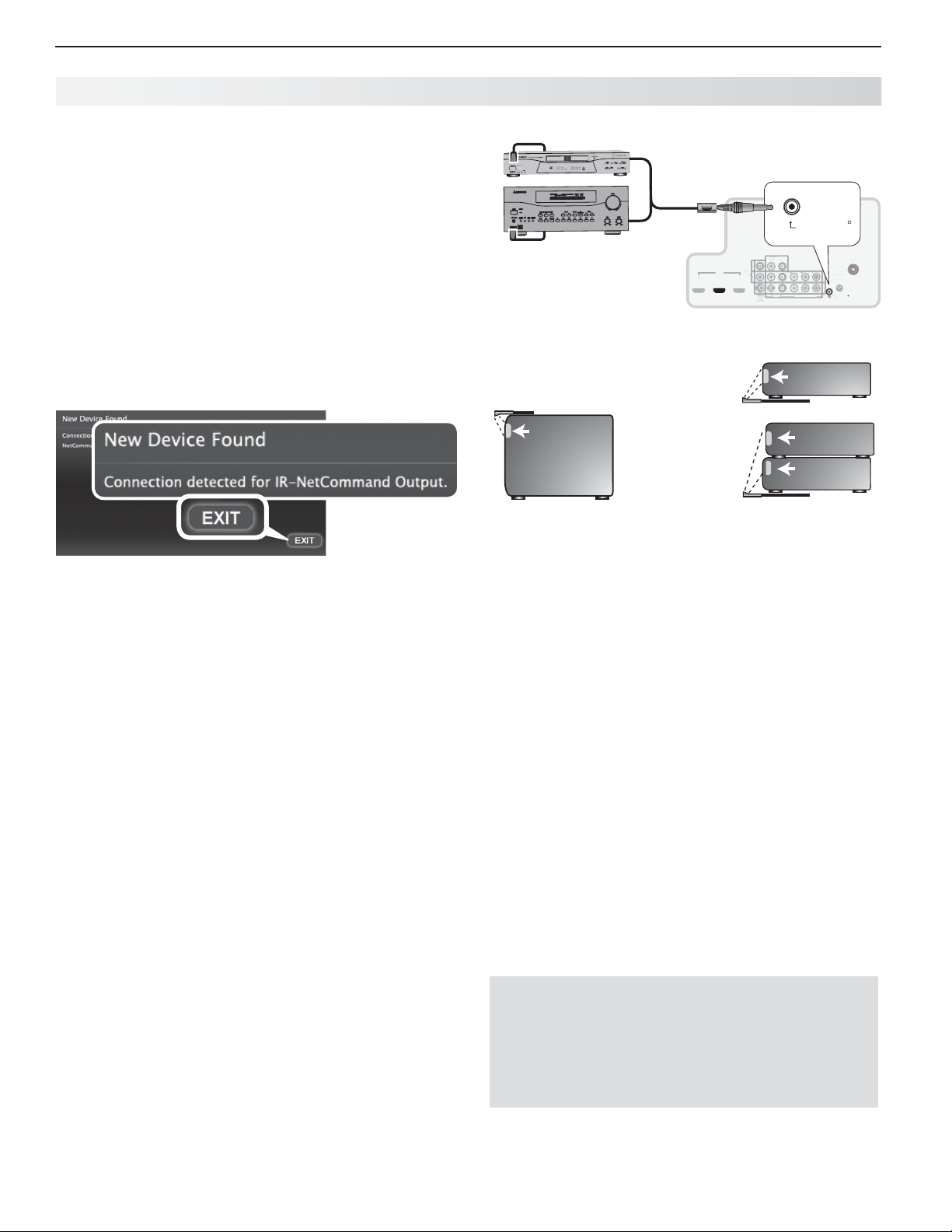
46 5. NetCommand IR Control (837 Series)
3
O
T
L
R
b
Y/ VIDE
O
b
2
U
1
C
AUDIO
(
)
(pp)
L
T
O
Y/ VIDE
O
3
GLASSES
NetCommand
Output
R
IR E mitter Placement
The Net Command system uses emitters connected
to the
IR–Net Command Output
jack to control other
devices such as DVD players, cable boxes, satellite
receivers, and VCRs.
IR emitter cables are available for purchase from
Mitsubishi. Request either part number 242D483020
(two-ended cable) or part number 299P254020 (fourended cable).
Connect the plug end of the supplied IR emitter
1.
cable to the
IR—Net Command Output
jack on the
TV back panel.
When the
2.
highlight EXIT and press
New Device Found screen displays,
ENTER
.
The New Device Found screen displays when you
connect the IR emitter.
Other A/V Device
S
H
C
L
A
IT
IG
D
D
N
U
O
R
R
SU
IR-
Output
NetCommand
R
A/V Receiver
INPUT
DVI/PC
DVI/P
TV Main
Panel
INPU
AUDIO
AUDI
L
R
L
AVR
AUDIO
AUDI
Y/ VIDEO
OUTPU
OUTPUT
HDMI
HDMI
HDMI
R
2
2
1
3
1
3
Pb
Y/ VIDEO
Pb
L
(480i / 480p / 720p / 1080i)
480i / 480p / 720p / 1080i
AUDIO
ANT
3D
D
Pr
GLASSES
EMITTER
INPUT 2
T
INPUT 1
INP
Pr
R
R
IR-
NetCommand
-
IR-
NetCommand
Output
Output
Connecting IR–Net Command Output
*3TFOTPS
*3TFOTPS
*OGSPOUPGBTJOHMF
BWFSBHFTJ[FEEFWJDF
0OUPQPGBTJOHMF
UBMMEFWJDF
*OGSPOUTIBSFECZ
UXPBWFSBHFTJ[FE
EFWJDFT
*3TFOTPS
*3TFOTPS
*3TFOTPS
Place IR emitters so the signal can be “seen” by the IR
sensor on each device.
If You are Unable to Locate
a Device’s IR Sensor
Position the emitter end with the emitter bulb facing
3.
the device’s remote control sensor. The bulb emits
infrared light in a cone-shaped pattern. Place the
bulb far enough from the sensor to allow the cone
pattern to reach the sensor.
In some cases, the emitter works better facing
downward from the top of the device. Experiment
to find what works best.
Secure the emitter ends in place using double-
4.
sided tape.
5.
Place any unused ends behind the devices to
prevent stray signals from reaching the IR sensors.
The IR sensor is usually behind the plastic window •
of the front display panel. Using a flashlight, you
may be able to see it as a round or square cutout.
If you cannot see the sensor and the device’s •
Owner’s Guide does not specify the location, do
the following using the device’s remote control.
Starting at one end of the plastic window, hold 1.
the device’s remote control about one-half
inch from the front of the device and press the
POWER
key.
If the device does not respond, move the 2.
remote control one inch toward the center and
try again. Repeat until the device responds.
Repeat the previous steps starting at the other 3.
end of the window. The sensor will be between
these two points.
IMPORTANT
Position IR emitters so that each device’s
sensor “sees” the signal from only one emitter.
Otherwise, a device receiving signals from
multiple sources (remote controls, IR emitters)
may not respond at all.
Page 47
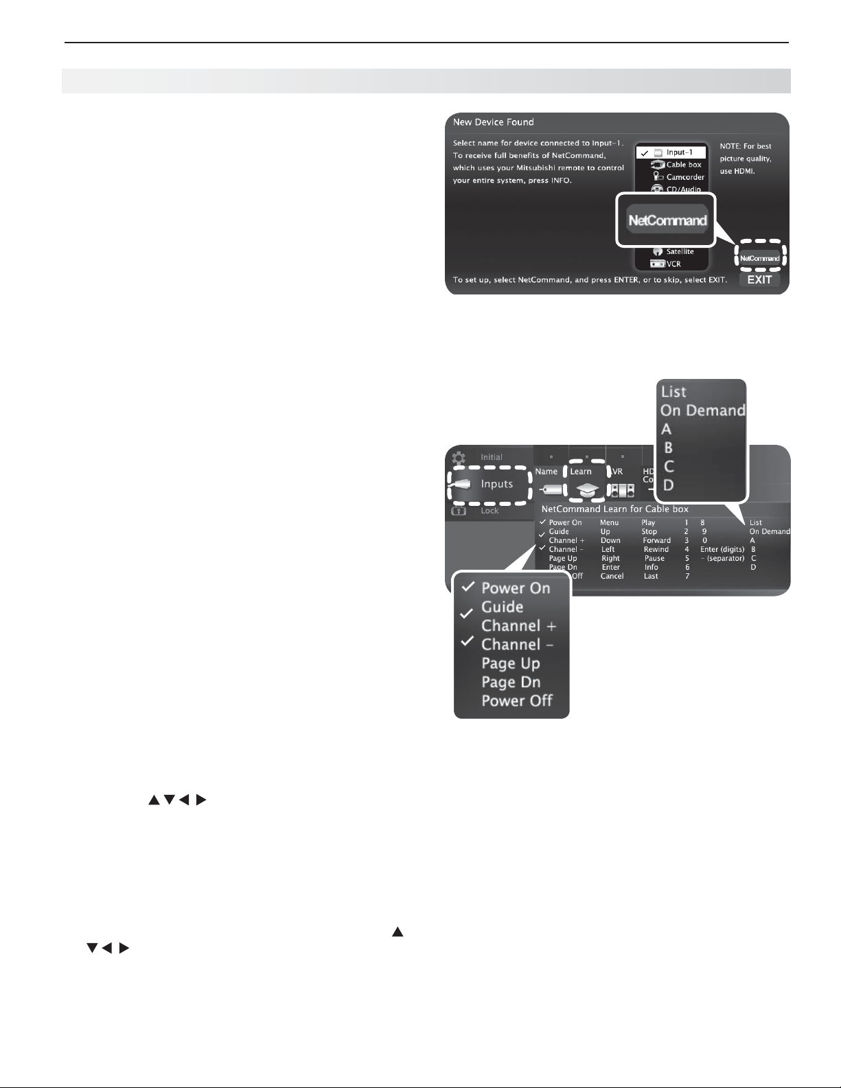
5. NetCommand IR Control (837 Series) 47
Initial Net Command Setup
To perform this procedure, you need:
The remote controls for both the TV and the •
device you want to control.
An IR emitter cable available from Mitsubishi•
Note: To set up an A/V receiver, see “Setting Up A/V
Receiver Control,” page 52 .
Connect and position the IR emitters for the
1.
devices you wish to control. See “IR Emitter Placement” on the opposite page .
Set the
2.
on the TV.
Open the Net Command
3.
TV’s remote control to TV mode and power
Learn screen as follows:
If working from the • New Device Found screen
after the device is first detected, highlight
NetCommand and press
Learn screen for the device.
If performing Net Command setup at any time •
after the device has been recognized through
Auto Input Sensing:
a. Press
b. Highlight the desired input icon and press
c. Press
ACTIVIT Y.
ENTER
to switch to that input.
MENU
, highlight Inputs, and highlight
Learn to open the Inputs > Learn screen
for the device.
ENTER
to open the
.
From the New Device Found screen, highlight
NetCommand and press ENTER to open the Learn
screen.
Device-specific keys in the
rightmost column can be accessed
with the MORE key after “learning.”
The first function highlighted in the
4.
is always Power On. Aim the TV’s remote control
at the TV and press
function.
When the
5.
device’s
key until a check mark appears next to Power On.
Press the
6.
to highlight other keys on the list. Repeat steps
4 and 5 for each additional function you wish to
control through Net Command.
Note: Device keys in the far right column will be asso-
If the device has a separate
7.
on the TV’s remote to highlight Power Off.
Repeat the earlier steps to “learn” the
If the device has no
Press
8.
current device.
Power On
remote control at the TV and hold the POWER
If the text stops flashing before the check mark •
appears, repeat the previous step.
To remove the key from Net Command control, •
press the
highlighted.
keys on the TV’s remote control
ciated with the remote control’s
“learned.” See the table on page 49 .
BACK
to finish Net Command “learning” for the
ENTER
to begin learning for that
text starts flashing, aim the
CANCEL
key while the key name is
POWER OFF
POWER OFF
Learn screen
MORE
key when
key, press
POWER OFF
key, skip this step.
key.
Inputs > Learn screen
Key names marked with a
check have been “learned.”
Adding or Removing Device Keys from
Net Command Control
Switch the TV to the device. Press
1.
light the device’s icon, and press
Open the
2.
When the
3.
Inputs menu and highlight the Learn icon.
Learn screen displays:
To add keys: • Continue as described earlier
under “Initial NetCommand Setup” on this
page .
To delete keys:• Highlight the name of the key
you wish to delete and press
TV‘s remote control to clear the check mark.
ACTIVIT Y
ENTER
CANCEL
, high-
.
on the
Page 48
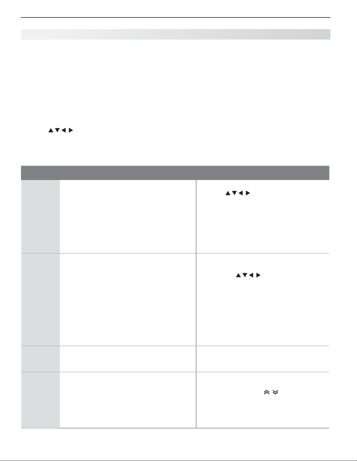
48 5. NetCommand IR Control (837 Series)
Operating Net Command-Controlled Devices
Controlling Most Device Types
As an example of NetCommand control, if you are
watching your cable box and you wish to tune to the
next channel higher, press
then sends the “learned” channel-up control signal to
the cable box.
Perform NetCommand setup for the device as
1.
described in this chapter.
When you wish to use the device, press
2.
Press
3.
4.
Press
to highlight the icon for the device.
ENTER
to switch the TV to the device.
CHANNEL UP
. NetCommand
ACTIVIT Y
.
S pecial Operation Methods
Key Name in
Learning Screen
Power On Manual Power On/Off
Special Operation Description and Setup How to Use
Use for devices that have only one
POWER
Note: if you have set up automatic input switching for
the A/V receiver, the A/V receiver will automatically switch to the correct input for the device.
key.
5.
To operate the device using the
control, press the side button to put the remote
control into
Point the remote control at the
6.
and press the key for the desired function.
Press the
7.
tions you may have “learned” for the device.
TV
mode.
MORE
key to access additional key func-
Press 1.
ACTIVIT Y
Press 2. to highlight the icon for the
device to be powered on or off.
With the 3. Activity menu still displayed, press
POWER
to send the power signal; you may
need to press
.
POWER
TV’s remote
TV (not the device)
twice.
Power On
Power Off
Menu Displaying a Menu for the Current Device
Guide Displaying the On-Screen Program Guide
Automatic Power On/Off
This feature is only for devices that have separate
POWER ON
remote controls. If your device does not have a
separate
Off learning position; use only the Manual Power
ON/OFF method described above.
In the NetCommand Learn screen:
a. “Learn” the Power On command in the
b. “Learn” the Power Off command in the
“Learn” the
Menu learning position.
(cable box or satellite receiver)
and
POWER OFF
POWER OFF
Power On learning position.
Power Off learning position.
MENU
key on the original remote in the
“Learn” the 1.
the Guide learning position.
Learn the 2.
original remote in the Page Up and Page
Down learning positions.
GUIDE
PAGE UP
keys on their original
key, do not use the Power
key on the original remote in
and
PAGE DOWN
keys of the
Note: If you press
menu displayed, the TV will turn off.
Press 4.
ENTER
To Power On the Device•
Press 1.
Press 2. to highlight the icon for
the device to be powered on or off.
Press 3.
device and NetCommand will send the
Power On command to the device.
To Power Off the Device•
When you turn the TV off, the TV sends all
learned Power Off commands to all devices.
Press
MORE
and then 1 to send the menu
command to the current device.
While watching the device, press 1.
display the guide.
Press 2.
PAGE UP/DOWN
Up/Dn commands for the guide.
POWER
without the Activity
to switch the TV to the device.
ACTIVIT Y
ENTER
.
to switch the TV to the
GUIDE
( ) to send the Page
to
Page 49
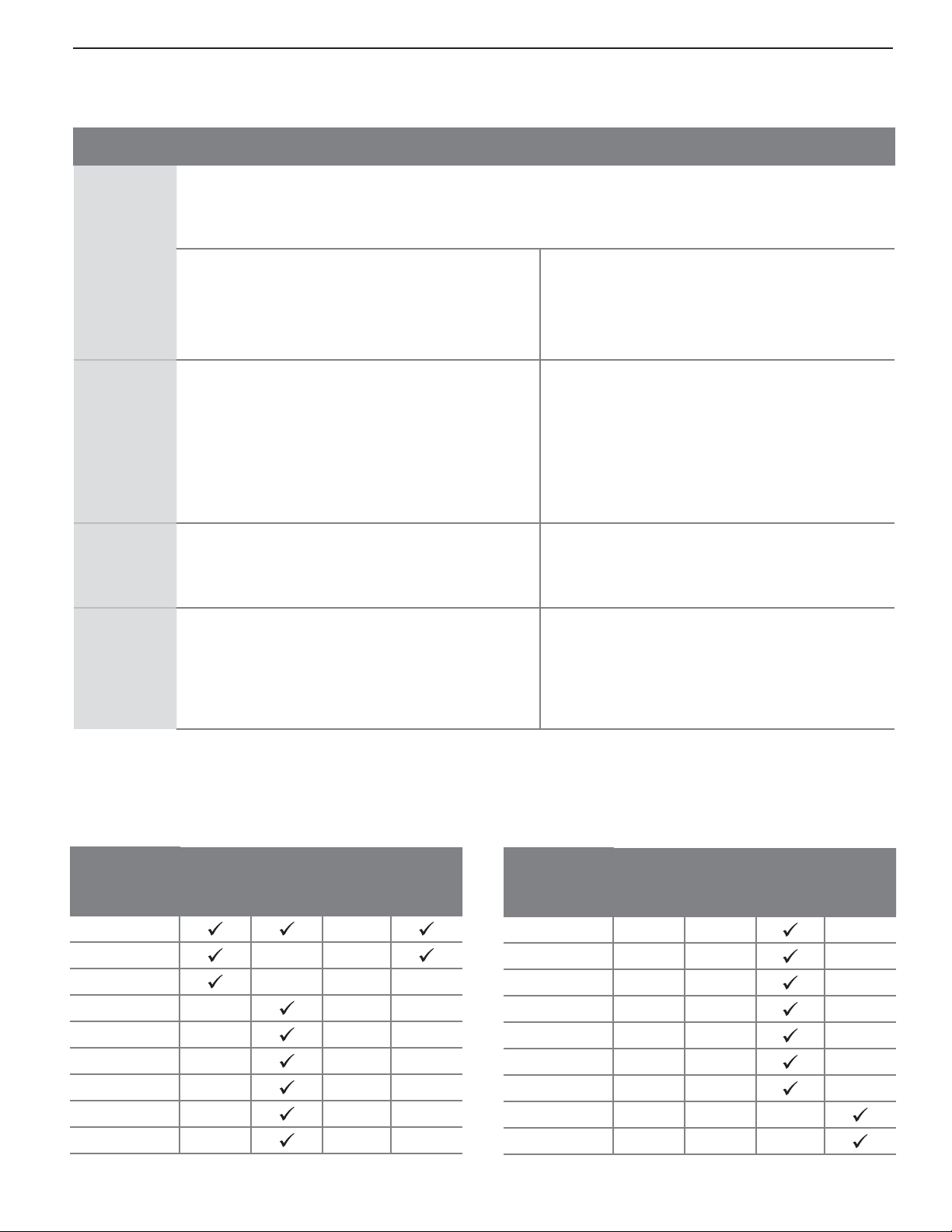
5. NetCommand IR Control (837 Series) 49
Key Name in
Learning Screen
Special Operation Description and Setup How to Use
Enter ENTER-Key Functions (cable boxes, satellite receivers, etc.)
Some devices have two keys that have “enter” functions. One key is for menus and is often labelled
Enter (digits)
SELECT
uses the same
When
when the original remote control uses the same
key for menus and channel selection:
Learn the
NetCommand Enter learning position.
When
nal remote control has a separate
this function):
Learn the
or OK. A second key is for use with number keys for direct channel selection. NetCommand
ENTER
key for both operations.
ENTER
has a menu or guide function or
Press 1.
menu or guide.
Press 2.
ENTER, SELECT,
or OK key in the
NetCommand will send the Enter signal for
menus.
ENTER
is for channel changes, i.e., the origi-
ENTER
key for
Press digit key(s) and then press
NetCommand will send the Enter signal for
channel selection.
ENTER
key for channel selection in
the NetCommand Enter (digits) learning posi-
tion. Use this learning position only if the original
remote control has separate keys for Enter in
menus and Enter for channel selection.
Cancel CANCEL as the Cancel or Exit Function
“Learn” the Cancel or Exit function in the
NetCommand Cancel learning position
Press 1.
guide.
Press 2.
the Cancel or Exit signal.
—
(separator)
The symbol “—” can serve as the separator
between a digital channel’s main and sub-channel
digits, e.g., digital channel 12-1 (main channel is
Press digit key(s) and press
NetCommand will send the channel-separator
signal.
12, sub-channel is 1).
“Learn” the channel separator function in the
NetCommand – (separator) learning position.
MENU
or
GUIDE
ENTER
within the menu and
MENU
or
GUIDE
to display the menu or
CANCEL
and NetCommand will send
to display the device’s
ENTER
.
CANCEL
.
The MORE Key Menu and NetCommand
Perform NetCommand setup for these device-specific
keys and then access their functions with the
Device
Key
VCR
Cable/
SAT
M enu
Input
SP/EP
List
On Demand
A
B
C
D
DVD/
DVR
MORE
A/V
key.
Receiver
Device
Key
Top Me n u
Angle
Audio (DVD)
Subtitle
Repeat
Bonus View
Setup
Surround
Night
VCR
Cable/
SAT
DVD/
DVR
A/V
Receiver
Page 50
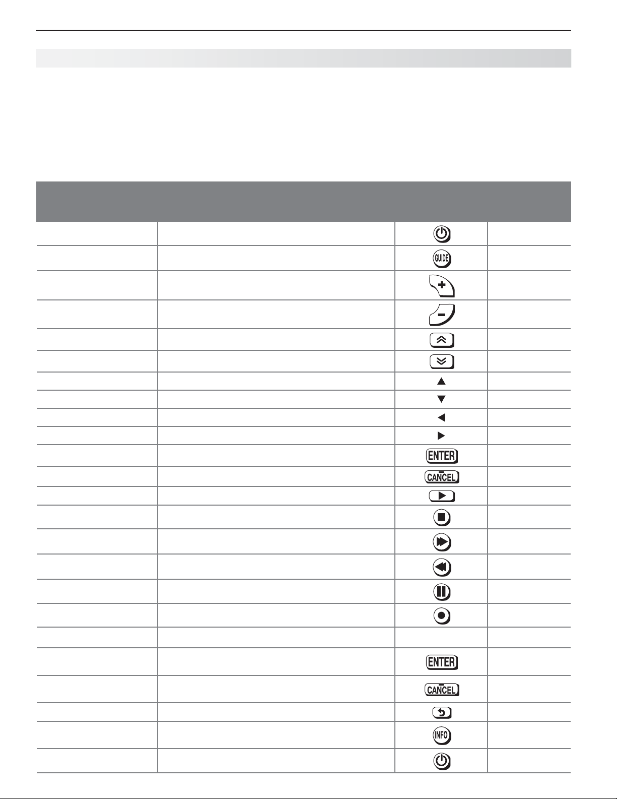
50 5. NetCommand IR Control (837 Series)
Operating NetCommand-Controlled Devices, continued
NetC ommand Specialized Device Keys
Refer to this chart when “learning” device keys. “Learn”
some, all, or none of the keys used for each device
type.
See page 48 for more on keys marked in the “Special
Operation Method” column.
Key Name in
Learning Screen
Power On Power On or Power ON/OFF (toggle)
Guide On-Screen Program Guide or DVD Disc Menus
Channel + Next Channel Higher
Channel – Next Channel Lower
Page Up Page Up in Guides
Page Dn Page Down in Guides
Up Arrow up
Down Arrow down
Left Arrow left
Right Arrow right
Enter Enter or Select (menus)
Cancel Cancel or erase (menus)
Play Start playback
Function
Name on TV
Remote Control
See Special
Operation
Method Table
9
9
9
9
Stop Stop playback
Forward Fast Forward
Rewind Rewind/Fast Reverse
Pause Pause playback
Record Start Recording
1, 2, 3, 4, 5, 6, 7, 8, 9, 0 Digits
Enter (digits) Use after entering digits to tune directly to a
channel by number
- (separator) Add digital channel separator between main
channel number and sub-channel number
Last Last Channel Recall
Info On-screen status display or information display May require two
Power Off Power Off
1, 2, 3, 4, 5, 6, 7, 8, 9, 0
9
9
keypresses
9
Page 51

6
51
Net Command IR Control of an A/V
Receiver
Several types of A/V receiver control can be set up
using the Inputs > AVR menu.
Power and volume.• See the next page .
Audio switching.• For most equipment setups, see
“Case 1: Automatic A/V Receiver Switching to the
TV Audio Input” page 53 .
Audio switching and surround sound.• To set up
switching to a surround sound device, see “Case
2: Automatic A/V Receiver Switching to a Surround
Sound Device” page 54
Audio and video switching over HDMI• . If your
A/V receiver has an HDMI output, it may be convenient to send audio and video to the TV over a
single HDMI cable through the A/V receiver. See
“Case 3: Automatic Audio and Video Switching via
HDMI,” page 54 .
Note: To set up control of other device types, see
“Initial NetCommand Setup,” page 47 .
Controlling an A/V Receiver
after NetCommand Setup
Switching Audio to and from the A/V
Receiver
Press
1.
2.
3.
Controlling A/V Receiver Power
With Any Connection Type
1.
2.
3.
4.
With an HDMI Connection
1.
2.
3.
MORE
and then
Press
Press
Press
Press
Press
Point the remote control at the
receiver) and press
receiver on or off.
Press
Highlight the A/V receiver icon.
Press
to show the Speakers option.
to select either AV Receiver or TV.
MORE
and then
to show the Speakers option.
to select AV Receiver.
ACTIVIT Y
POWER
.
.
9
(AUDIO)
9
(AUDIO)
POWER
to power the A/V
.
.
TV (not the A/V
Controlling Other A/V Receiver Functions
With the A/V receiver powered on and selected, the
TV’s remote control operates the volume and mute
functions. Also, when you switch to a device in the
Activity menu, the A/V receiver automatically switches
to the correct audio input for the device.
Page 52
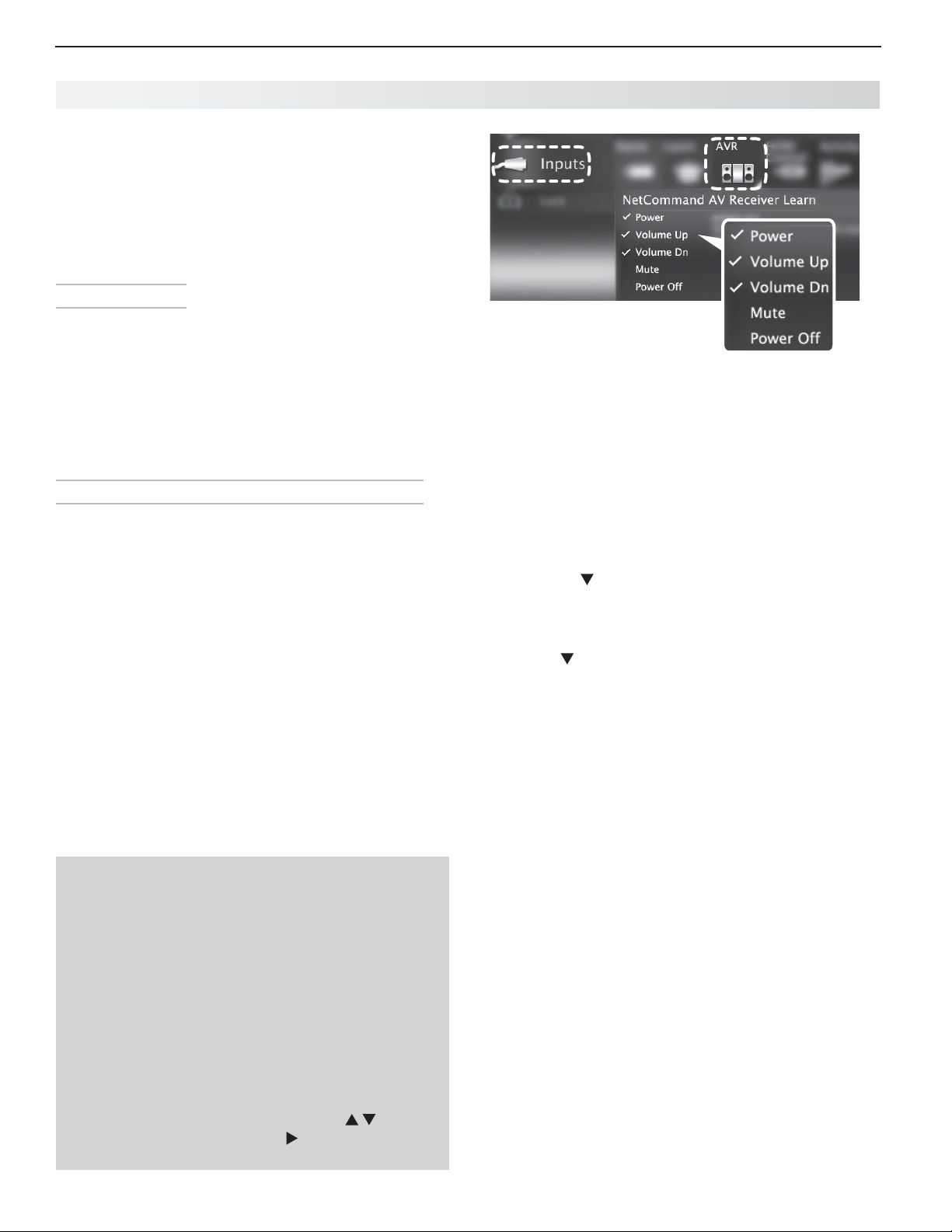
52 6. NetCommand Control of an A/V Receiver (837 Series)
Setting Up A/ V Receiver Control
Pow er and Volume
Perform this setup to control the A/V receiver power
and volume with the TV’s remote control.
To perform this setup you need:
The remote controls for both the TV and the •
A/V receiver.
An IR emitter cable available from Mitsubishi.•
Before You Begin
Connect your A/V receiver to the TV and any addi-
1.
tional devices. See “Setting Up TV Inputs,” page 10
and “TV Connections,” page 14 .
Connect the IR emitter cable to the TV and position
2.
the IR emitter where it can send signals to the A/V
receiver. See “IR Emitter Placement,” page 46 .
Set the
3.
side button.
Setu p to Control A/V Receiver Power and Volume
Open the
1.
The first function highlighted in the
2.
always Power. Aim the TV’s remote control at the
TV and press
TV’s remote control to TV mode using the
Inputs > AVR screen in one of two ways:
If using the • New Device Found screen for the
A/V receiver, highlight NetCommand and press
ENTER
to open the AVR screen.
If performing Net Command setup at any time •
after Auto Sensing:
Press
MENU
, highlight Inputs, and highlight AVR
to open the AVR menu.
AVR screen is
ENTER
to begin learning for Power.
Inputs > AVR screen. Perform
Net Command IR “learning” for A/V
receiver power and volume keys.
When the
3.
receiver’s remote control at the TV and hold the
POWER
next to Power.
Press the 4. key on the TV’s remote control to highlight
other keys in the list. Repeat steps 2 and 3 for each additional function you wish to control through Net Command.
If the A/V receiver has a separate
5.
press on the TV’s remote to highlight Power Off.
Repeat steps 2 and 3 to “learn” the
If the device has no
When finished “learning” the power and volume
6.
keys, either
Power text starts flashing, aim the A/V
or
POWER ON
If the text stops flashing before the check mark •
appears, repeat this step.
To remove the key from Net Command control, •
press the
highlighted.
To watch TV, press •
To continue with Net Command setup to control •
switching of A/V receiver inputs, highlight
NEXT and press
key until a check mark appears
CANCEL
key while the key name is
POWER OFF
POWER OFF
POWER OFF
BACK
ENTER
key, skip this step.
.
.
key,
key.
IMPORTANT
To hear audio sent from the TV to the A/V receiver,
you must have:
Physically connected the TV to the A /V receiver •
via the analog or digital audio output.
Assigned, if needed, the name AVR if using an •
HDMI A/V receiver.
“•
Learned” the IR codes for the A/V receiver
inputs.
Assigned the TV’s audio output to the correct •
input in the Net Command Inputs > AVR menu.
Selected the A/V receiver as the audio source. •
Press MORE then 9 (AUDIO), then
the Speakers option,
Receiver.
then
to select the A/V
to show
Page 53
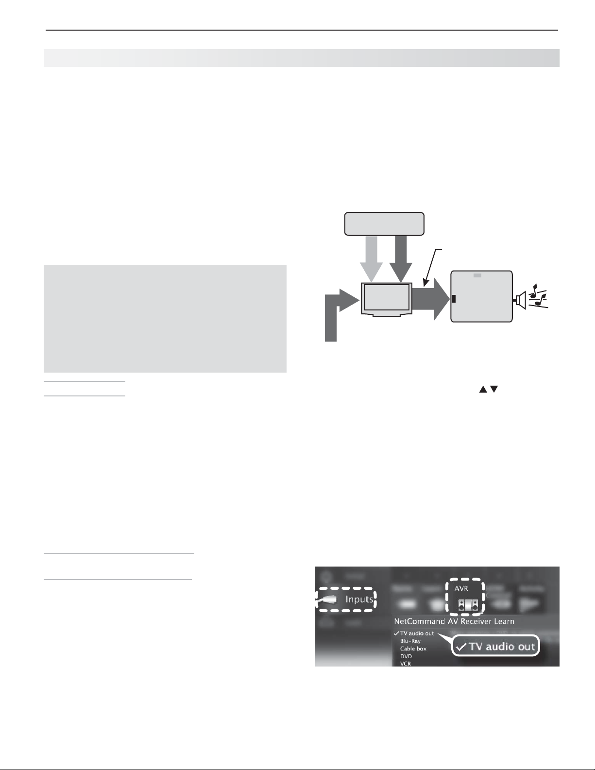
6. NetCommand Control of an A/V Receiver (837 Series) 53
Setting Up A/V Receiver Control, continued
Automatic Au
The following setups enable the A/V receiver to switch
automatically to the correct input when you select a
device in the TV’s Activity menu.
Three different connection arrangements are described
here. Review the descriptions to find the setup needed
for your equipment.
To hear digital surround sound from a source device
you must use the setup described for Case 2
To set up control of an A/V receiver you need:
The remote controls for the TV and A/V receiver.•
An IR emitter cable available from Mitsubishi.•
Connecting cables•
All audio from what you are watching on the TV is
always available from both the TV’s AVR AUDIO
OUTPUT and DIGITAL AUDIO OUTPUT jacks.
To use the digital surround sound capabilities of
your A/V receiver however, you must connect the
audio output from your DVD player, satellite receiver,
or cable box directly to the A/V receiver.
dio or Audio/Video Switching
.
IMPORTANT
Analog Stereo Audio. •
analog stereo output (such as a VCR) can be sent either
directly to the A/V receiver or through the TV first.
Mitsubishi recommends you send audio through the
TV as shown in the example. The TV converts analog
audio to digital format to send to a digital A/V receiver.
HDMI Digital Stereo Audio. • Digital stereo audio
from an HDMI connection is available both in digital
and analog format from the TV’s analog and digital
audio output jacks.
VCR with
Analog Audio Output
video
analog audio
TV
Incoming Coaxial Cable
audio + video
to TV’s ANT input
Important:
audio output to the A/V receiver’s TV audio input jack.
To use this setup, you must connect the TV’s
Audio from sources with only
audio output from
TV (digital or analog)
DVD audio
TV audio
out
input
TV audio input
A/V Receiver
Before You Begin
Connect your A/V devices to the TV and connect
1.
your A/V receiver to the audio outputs on the TV
and the DVD player. Note the name of the device
connected to each A/V receiver input. See initial
setup, page 10 , and “TV Connections,” page 14 .
Position Net Command IR emitters as described in
2.
“IR Emitter Placement,” page 46 .
Set the TV’s remote control to
3.
side button.
Open the
4.
and press
menu.
Case 1: Automatic A/V Rec eiver
Switching to the TV Audio Input
Most devices are set up to use the TV’s audio output like
the VCR in this example; analog audio from the device is
sent through the TV to the A/V receiver’s TV audio input.
Use this setup for:
Audio Available from TV only. • Send audio from
the
analog or digital audio output.
Use this setup to make the A/V receiver switch to its
designated TV audio input when viewing programming
from the
Inputs > AVR menu, highlight NEXT
ENTER
to display the device-key-learning
ANT
input to the A/V receiver from the TV’s
ANT
input.
TV
mode using the
In the
1.
2.
3.
4.
5.
Case 1: Net Command setup for controlling A/V
receiver switching to the A/V receiver’s audio input from
the TV. The list displayed represents inputs in use. The
device names are those you assigned during Auto Input
Sensing or in the Inputs > Name menu..
Inputs > AVR menu, press to highlight
TV audio out as the A/V receiver input to control.
Press
ENTER
on the TV’s remote control.
While the text
hold the
control.
When a check appears next to
release the
If the text stops flashing before the check mark •
appears, repeat this step.
To erase the IR code just “learned,” press •
CANCEL
Press
MENU
for another audio source.
TV audio out is flashing, press and
TV INPUT
key on the A/V receiver’s remote
TV audio out,
TV INPUT
while the name is highlighted.
if finished or continue with Case 2 setup
key.
Page 54
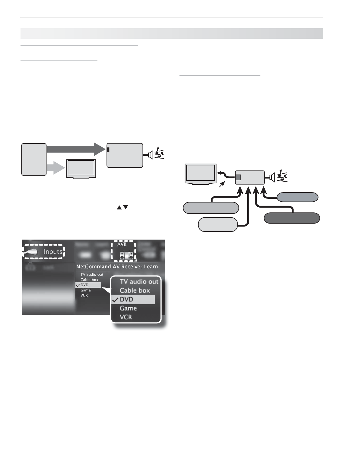
54 6. NetCommand Control of an A/V Receiver (837 Series)
Setting Up A/V Receiver Control, continued
Ca se 2: Automatic A/V Receiver Switching
to a Surround Sound Device
Note: Use this setup to send digital surround sound
from a device directly to your sound system.
A device can send digital surround sound such as Dolby
Digital or DTS directly to the A/V receiver. The device might
be a DVD player, cable box, or satellite receiver, and could
have HDMI output. A DVD player is used in this example.
Your setup may include additional devices with digital
surround sound connected directly to the A/V receiver.
These devices might be a DVD player plus a cable box
or satellite receiver.
%7%1MBZFS
XJUI
%JHJUBM
4VSSPVOE
4PVOE
Case 2: A/V receiver audio from a device providing
surround sound directly to the A/V receiver
In the
1.
the name of the A/V receiver input to control. In this
example, it is the DVD input.
Press
2.
EJHJUBMTVSSPVOETPVOE
WJEFP
Inputs > AVR menu, press to highlight
ENTER
57
on the TV’s remote control.
%7%BVEJP
JOQVU
"73FDFJWFS
5.
If finished, highlight
continue to set up additional A/V receiver audio
sources.
Case 3: Automatic Audio and
Vi deo Switching via HDMI
If your A/V receiver has an HDMI output, it may be
convenient to route video signals from multiple devices
over a single cable to the TV. Use this procedure to set
up NetCommand control of the A/V receiver’s audio
and video switching over a single HDMI cable. The
connected source devices can be analog, digital, or a
mixture or the two. When this setup is complete, you
can use the TV’s Activity menu to select a video device
connected to the A/V receiver.
TV
HDMI Cable
EXIT and press
A/V Receiver
HDMI
Output
ENTER
or
VCR
Blu-ray player
DVD player
Cable box
Case 2: Net Command setup for
controlling A/V receiver switching
to the A/V receiver’s DVD input. The list contains
connected inputs with names assigned during Auto
Input Sensing.
While the text
3.
DVD INPUT
When a check appears next to
4.
DVD INPUT
If the text stops flashing before the check mark •
appears, repeat this step.
To erase the IR code just “learned,” press •
CANCEL
DVD is flashing, press and hold the
key on the A/V receiver’s remote control.
DVD, release the
key.
while the name is highlighted.
More About Using an HDMI Connection
Audio from devices connected directly to the TV •
can be heard from the TV speakers only. To send
audio to the A/V receiver from such devices, use
one of the optional audio connections shown in the
diagram on the opposite page . For example, use
an optional audio connection if you wish to use the
A/V receiver speakers to hear audio from:
The -
ANT
input
A game or camcorder connected to the conve- nience input (
In some circumstances, audio from a device con-•
nected to the A/V receiver may not be passed over
the HDMI cable to the TV speakers. In these cases
you must use the A/V receiver speakers to hear
audio.
Before You Begin
To complete these steps you will need:
The remote controls for both the TV and the •
A/V receiver.
An IR emitter cable available from Mitsubishi.•
An HDMI-to-HDMI cable to connect the A/V •
receiver to the TV and cables necessary to
connect devices to the A/V receiver.
INPUT 3
).
Page 55
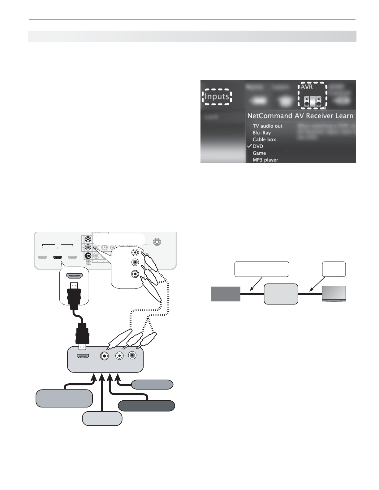
6. NetCommand Control of an A/V Receiver (837 Series) 55
I
AVR
O
OUTPU
L
Y/
O
r
P
b
P
r
2
U
1
C
A
O
(
)
(pp)
INPUT
AUDIO
Y/ VIDE
O
3D
GLASSES
EMITTER
NetCommand
O
t
R
Setting Up A/V Receiver Control, continued
Connect your audio/video devices to the A/V
1.
receiver. Note the name of the device connected
to each A/V receiver input. This information will be
needed later to set up NetCommand’s automatic
input switching.
Connect the A/V receiver to the TV with an HDMI-to-
2.
HDMI cable.
Connect the IR emitter cable to the TV and position
3.
the IR emitter where it can send signals to the A/V
receiver. See “IR Emitter Placement,” page 46 .
Se tup to Control Automatic Audio
and Video Switching via HDMI
Power on the A/V receiver.
1.
Set the
2.
side button.
Power on the TV.
3.
When the
4.
device name AVR if it is not recognized automatically.
Navigate to the
5.
within the New Device Found screen, highlight
NetCommand and press
TV’s remote control to TV mode using the
New Device Found screen displays, select
Inputs > AVR menu or, from
ENTER
.
INPUT
DVI/PC
DVI/P
AUDIO
L
R
R
L
L
T
R
DIGITAL
R
AUDIO
OUTPUT
TV main panel
Y/ VIDEO
Y/ VIDEO
L
AUDIO
UDI
VIDE
Pb
Pb
AVR
AUDIO
Pb
(480i / 480p / 720p / 1080i)
480i / 480p / 720p / 1080i
OUTPUT
Pr
P
L
Pr
R
DIGITAL
AUDIO
OUTPUT
INPUT 2
INPUT
T
INPUT 1
INP
AVR
AUDI
AUDIO
HDMI
HDM
HDMI
1
OUTPUT
2
3
Optional analog or
digital audio
connection
GLASSES
EMITTER
IR-
NetCommand
-
utpu
Output
ANT
3D
R
6.
Perform the procedure in
“Case 2: Automatic A/V
Receiver Switching to a Surround Sound Device”
on the opposite page .
To set up A/V switching over HDMI, choose your
devices from a list. Unlike the device list described for
Case 2, this generic list contains more than just the
devices detected in your setup.
Net Command Control of a Device Connected to an HDMI A/V Receiver
Use this setup to have Net Command control a device
sending audio and video through the A/V receiver to the
TV via HDMI.
Source
Device
Any Connection
Type
A/V
Receiver
HDMI
Cable
TV
The A/V receiver’s remote control key for the input must
have been “learned” previously using “Setup to Control
Automatic Audio and Video Switching via HDMI” on this
page .
A/V receiver
with HDMI
output
HDMI OUT
DIGITAL
AUDIO
LR
VCR
High-definition
DVD player
DVD player
Cable box
Multiple video inputs through a single H DMI cable. You can
connect multiple video devices to an A/V receiver that has
an HDMI output. The optional audio connection allows you
to hear, through the A/V receiver, devices connected to the
TV only, e.g., an antenna on the
ANT
input.
Set up Net Command control of A/V receiver audio/
1.
video switching via HDMI as described on this
page .
Press
2.
BACK
to close any open menus and return to
normal TV viewing.
Press
3.
4.
ACTIVIT Y
.
Highlight the icon for the A/V receiver input you
wish to control.
Press
5.
ENTER
to switch the TV to the A/V receiver
and the A/V receiver to the device.
Open the
6.
Perform Net Command “learning” for the device by
7.
Inputs > Learn menu.
following the steps in “Initial NetCommand Setup,”
page 47 .
Page 56

56
Appendices
Appendix A : Bypassing the Parental Lock .............. 57
Appendix B : Programming the Remote Control ........... 59
Appendix C : HDMI Control of CEC Devices .............. 66
Appendix D : TV Care ........................... 69
Appendix E : Troubleshooting ...................... 72
Page 57
Appendices 57
Appendix A: Bypassing
the Parental Lock
Mitsubishi DLP Projection TV
C9 Series
737 Series
837 Series
Bypassing the Parental Lock
After you set the lock, you must use your pass code to:
View a locked program•
View the locked TV•
Cancel the lock•
Enter the • Lock menus
If you forget your pass code, you can view the locked
TV without entering your pass code. When prompted
for the pass code, press the number
keys on the TV remote control at the same time. This
process temporarily unlocks the TV.
When entering the Lock menu, you are prompted to
enter a pass code.
• To change the pass code, press
at the same time. Either enter a new pass code to
open the Lock menu and make changes or press
BACK
to close the menu.
9
and
9
and
(
LAST
(
LAST
)
)
Lock Bypass Instructions Have Been Filed for
Future Reference
IMPORTANT
Cut along the dotted line and file bypass
instructions in a safe place for future
reference.
• If any of the locks are turned on and you exit the
menus when prompted for a new code, the old
code and all lock settings are retained.
• If all locks are turned off and you exit the menus
when prompted for a new code, then the previous
code is erased.
IMPORTANT
When changing or deleting your pass code,
you must use the remote control included
with this TV. You cannot use a Mitsubishi
remote control from another component or a
“universal” remote.
Page 58

58 Appendices
This page intentionally left blank
Page 59
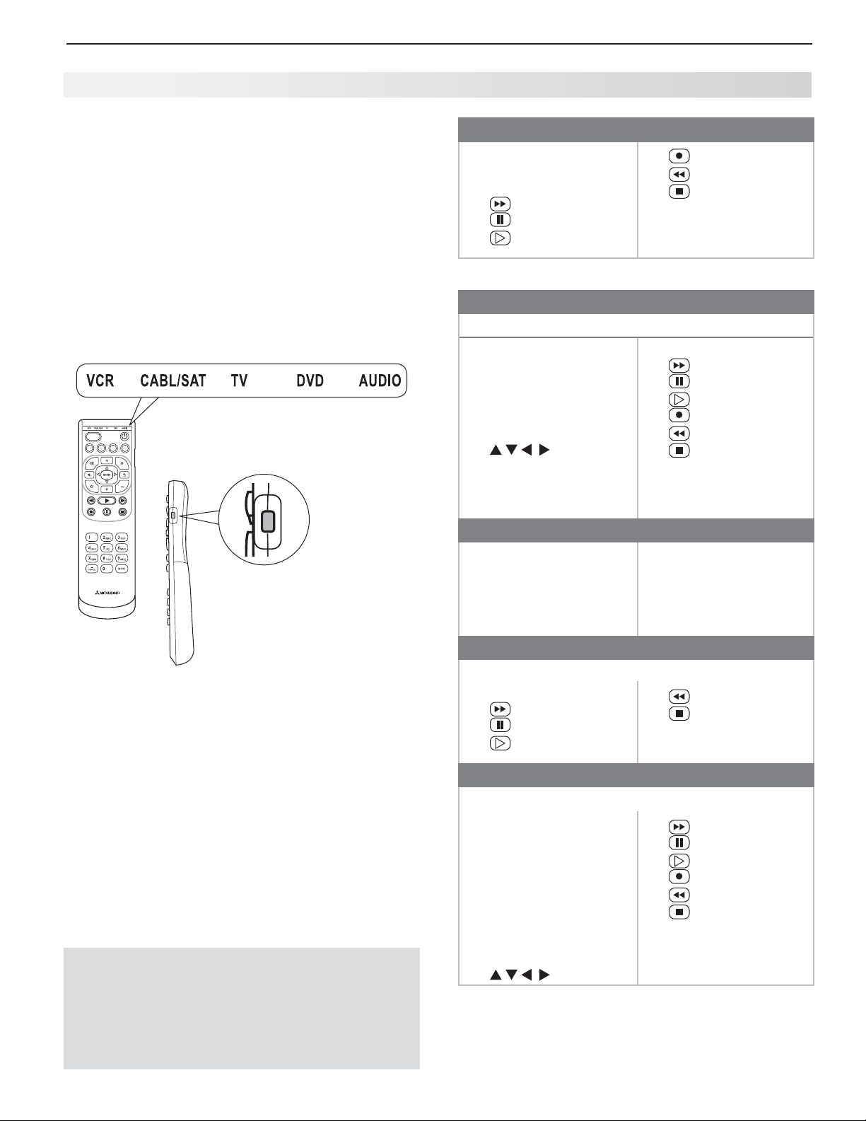
Appendices 59
Appendix B: Programming the Remote Control
This appendix explains programming the TV’s remote
control to operate other A/V devices. This is distinct
from Net Command control.
Functions Available for Other A/V Devices
The TV’s remote control can be programmed to operate
other types and brands of A/V products. The functions
performed in each switch position vary depending on
the product. Not all functions work for all models. The
most common functions available are listed on this
page.
ACTIVITY
GUIDE MENU INFO BACK
TV modes
To use the remote after
programming, press the side
button to change the control
mode to match the device
type.
The M ORE Menus
The
MORE
key displays a menu showing additional key
functions available for a device type after programming
the remote control.
VCRs and DVRs
•
CHANNEL UP/DN
•
POWER
•
SLEEP (from
• (
•
• (
FAST FORWARD
(
PAUSE
PLAY
MORE menu)
)
)
)
•
• (
• (
•
•
•
(
RECORD
REVERSE
STOP
GUIDE
MENU
0–9
Number Buttons
)
)
)
(DVR only)
(DVR only)
Mitsubishi VCRs are compatible with some additional keys.
Cable Boxes and Satellite Receivers
(not all functions for all models)
•
PAGE UP/DOWN
•
CANCEL
•
CHANNEL UP/DN
•
ENTER
•
GUIDE
•
POWER
•
•
LAST (ENTER
; for chan-
The record/playback keys:
• (
• (
•
• (
• (
• (
FAST FORWARD
PAUSE
)
(
PLAY
)
RECORD
REVERSE
STOP
)
)
)
)
nels on some models)
•
0–9
Number Keys
A/V Receivers
•
MUTE
•
POWER
•
SLEEP (from
•
VOLUME
•
0–9
MORE menu)
Number Buttons
• Direct Input Selection
buttons: numbers
and
LAST
(on some
Mitsubishi models)
CD Players
(not all functions for all models)
•
SLEEP (from
• (
• (
• (
FAST FORWARD
PAUSE
PLAY
MORE menu)
)
)
)
• (
• (
•
0–9
REVERSE
STOP
)
)
Number Buttons
DVD Players
(not all functions for all models)
IMPORTANT
Some manufacturers may change their
products or they may use more than one
remote control system. The TV’s remote
control may be unable to operate your A/V
equipment in these cases.
•
CANCEL
(on some
models)
•
CHANNEL UP/DN
track skip on some
models)
•
ENTER
•
MENU
•
POWER
•
SLEEP (from
•
(for
MORE menu)
• (
•
• (
• (
• (
• (
•
0-9
FAST FORWARD
(
PAUSE
)
PLAY
)
RECORD
REVERSE
STOP
)
)
)
Number Keys
)
Page 60
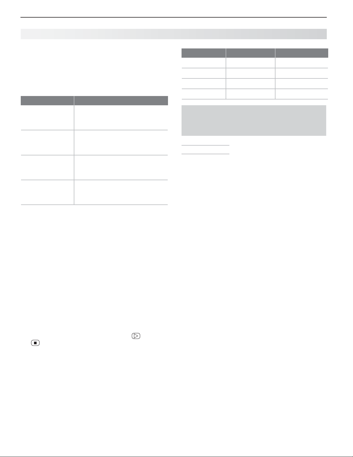
60 Appendices
Appendix B: Programming the Remote Control, continued
Program ming the Remote Control
Press the side button on the remote control to
1.
change to the correct mode for the product you
want to control. Refer to the table below. Only
one of each device type can be controlled in each
mode.
Mode Affected Device
CABLE/SAT
VCR
DVD
AUDIO
Press and hold
2.
several seconds until the mode indicator blinks
twice and goes off.
Release the
3.
Enter the first five-digit code listed for your equip-
4.
ment.
The mode indicator blinks twice when you •
start to enter the code and then once for each
additional keypress.
The mode indicator blinks twice when you finish •
entering a valid code.
If you need to start over or wish to exit pro-•
gramming mode, temporarily change to a
different mode using the side button.
Point the remote control at the equipment and
5.
press
POWER
function, press a different key, such as (
(
STOP
),
If the equipment responds, the remote control •
is properly programmed.
If the equipment does not respond, repeat •
steps 2–4 with the next five-digit code listed for
your equipment.
Once you have found the correct code, write it in
6.
the space below for future reference.
Cable Box
DTV Receiver
Satellite Receiver
VCR
DVR
DVD Player/Recorder
DVD Player/Recorder
DVR
VCR
A/V Receiver
Audio Amplifier
CD Player
POWER
on the remote control for
POWER
key.
. If the product has no power on/off
VOLUME UP
, or
MUTE.
PLAY
),
Mode
CABLE/SAT
VCR
DVD
AUDIO
You may need to reprogram the remote control after
changing the batteries. Record the codes for each
mode in the space provided to make this faster.
Code Verification
To determine the code programmed for any mode:
Set the mode to the one you wish to verify.
1.
Press and hold
2.
several seconds until the
and goes off.
Press keys
3.
Press
4.
5.
1
and count the blinks of the power key.
Write down the number of blinks as the first digit of
the code.
Repeat step 4 for the second, third, fourth, and fifth
digits of the code.
Device Type Code
IMPORTANT
POWER
on the remote control for
mode indicator
9 9 0
blinks twice
Au dio Lock: Universal A/V Receiver
Control
With Audio Lock enabled, the remote control operates
volume and mute on the A/V receiver in all modes set by
the side button. Activate Audio Lock if you normally use
an A/V receiver with your TV and other A/V equipment.
Program
1.
described in “Programming the Remote Control” on
this page .
With the remote control in
2.
on the remote control for several seconds until the
mode indicator blinks twice and goes off.
Press keys
3.
The mode indicator will blink twice to indicate Audio
Lock is active.
To Reset the Remote Control to Operate Volume
and Mute for the TV Speakers
Press and hold
1.
mode indicator blinks twice and goes off.
Press keys
2.
The mode indicator will blink four times to indicate
Audio Lock has cleared.
AUDIO
mode for your A/V receiver as
AUDIO
mode, hold
9 9 3 ENTER
POWER
for several seconds until the
9 9 3 VOLUME UP
.
POWER
Page 61

Appendices 61
Appendix B: Programming the Remote Control, continued
Programming Codes
Audio Amplifi ers
Adcom 41100, 40577
Altec Lansing 41742
Bel Canto
Design
Bose 40674
Carver 40892
Cary Audio
Design
Classe 41461
Flextronics 41879
Halcro 41934
Harman/
Kardon
JVC 40331
Krell 41837
Left Coast 40892
Lexicon 41802, 41145
Marantz 40892
Mark
Levinson
Parasound 41934
Philips 40892
Polk Audio 40892
Victor 40331
Yamah a 40 3 54
Cable Boxes
A-Mark 10144, 10008
ABC 10237, 10008
Acorn 10237
Action 10237
Active 10237
Americast 10899
Amino 11822, 11602
Archer 10237
Bell South 10899
Century 10008
Cisco 11982, 11877, 10877
Comcast 11982
Digeo 12187
Director 10476
GE 10144
General
Instrument
GoldStar 10144
Hitachi 10008
i3 Micro 11602
Insight 10476
Jerrold 10476
Memorex 10000
Mo t oro la 11376 , 112 5 4, 10 476
Myrio 11822, 11602
Nova Vision 10008
Novaplex 10008
Pa ce 118 77, 10 87 7, 10 23 7,
Panasonic 11982, 10144, 10008,
41583
41879
40892
41483
10476
10008
10000
Cable Boxes
Paragon 10525, 10008, 10000
Penney 10000
Philips 11305
Pione er 11877, 10877, 10533,
10144
Pulsar 10000
Quasar 10000
Runco 10000
Samsung 10144
Scientific
Atlanta
Sejin 11602
Sony 11006
Sprucer 10144
Toshiba 10000
US Electronics
Videoway 10000
Zenith 10899, 10525, 10000
CD Players
Acoustic
Research
Akai 40083
Burmester 40420
California
Audio Labs
DKK 40000
Fisher 40000
Garrard 40420
Hafler 40173
Harman/
Kardon
Inkel 40180
Integra 40101
JVC 41294, 40072
Kenwood
KLH 41711, 41318
Koss 41317
LG 41208
Magnavox 40038
Marantz 40626, 40435, 40180,
McIntosh 41703
MCS 40029
Memorex 40420, 40000
MGA 40083
Miro 40000
Mitsubishi 40098, 40083
Modulaire 40420, 40180, 40087,
MTC 40420
NAD 41208
Onkyo 41327, 40101
Optimus 40420, 40087, 40037,
Panasonic 40752, 40388, 40029
1187 7, 10 8 77, 10 47 7,
10237, 10008, 10000
10008
40420
40029
41202, 40173, 40100,
40083
40626, 40190, 40037,
40029, 40000
40038, 40029
40000
40000
CD Players
Parasound 40420
Penney 40029
Philips 40626
Pioneer 41087
Proceed 40420
Quasar 40029
RadioShack 40420, 40180, 40000
RCA 40420
Realistic 40420, 40180, 40087,
40000
Roksan 40435
Rotel 40420
Sansui 40000
Sanyo 40087, 40000
Sharp 40180, 40037
Sherwood 41950, 40180
Sony 41364, 40490, 40185,
40100, 40000
Symphonic 40180
Tasca m 40420
TDK 41208
Teac 40490, 40420, 40180
Techn i cs 40 029
Victor 40072
Wards 40087
Yamaha 41292, 40490, 40036
Yorx 40000
A/V Receivers
ADC 40531
Aiwa 416 41, 41405, 41388,
41243, 40189, 40121
Alco 41390
AMC 41077
Anam 41609, 41074
Arcam 41189
Audiotronic 41189
Audiovox 41390
Bose 41933, 41841, 416 29,
4125 3 , 41229, 40 6 39
Cairn 40189
Capetronic 40531
Carver 41289, 41189, 40189,
40121
Curtis
Mathes
Daewoo 41250
Denon 4136 0, 4130 6, 41142,
Emerson 40531
Fisher 41801
Grundig 40189
Harman/
Kardon
Hitachi 41801
In signia 42169, 41893, 41077,
40014
40121
41306, 4130 4, 41289,
40891, 40189, 40110
41030
Page 62
62 Appendices
Appendix B: Programming the Remote Control, continued
Programming Codes, continued
A/V Receivers
In te g ra 41805, 41320, 41298,
40842
JBL 41306, 40110
JVC 42331, 41643, 41495,
41374, 41282, 41058
Kawasaki 41390
Kenwood 41570, 41569, 41313
KLH 41428, 41390
LG 42197, 41293
Linn 40189
Magnavox 41514, 41269, 41266,
41189, 40531, 40189
Marantz 41289, 41269, 41189,
40891, 40189
McIntosh 41289
Micromega 41189, 40189
Mi tsubishi 41957, 419 2 2, 41921,
41920, 41393
Myryad 41189
Nakamichi 41313
Onkyo 41905, 41805, 41320,
41298, 40842
Optimus 41074, 41023, 40531,
40121, 40014
Pa n a sonic 42967, 41764, 41763,
41633, 41548, 41518,
41509, 41316, 41308,
4128 8, 41275
Ph ilips 41269, 4126 6, 41189,
40891, 40531, 40189
Pi o n e er 419 35, 41384, 41123,
41023, 40630, 40531,
40150, 40014
Polaroid 41508
Polk Audio 41289, 40189
Proscan 41254
RadioShack 41609
RCA 4160 9, 41511, 41390,
4125 4, 41123, 41074,
41023, 40531
Realistic 41609, 40121
Revox 40189
Rio 41869
Samsung 41500, 413 0 4, 412 9 5
Sansui 41189, 4018 9
Sanyo 41801
Sherwood 42169, 4190 5, 41077
Sherwood
Newcastle
Sonic Blue 41869
Sony 41858, 41822, 41759,
Stereophonics
Sunfire 41313
Tea c 413 9 0, 41074
42169
41758, 41658, 416 2 2,
41558, 41441, 41382,
4125 8 , 41131, 41058
41023
A/V Receivers
Technics 41518, 413 0 8
Thorens 41189
Toshiba 41788, 41123, 40842
Venturer 41390
Wards 40189, 40014
Yam aha 41815, 41476, 41376 ,
41375, 41331, 41276,
41176, 41023, 4 0176
YBA 41921
Zenith 41293
Satellite Receivers
Bell ExpressVu
Chaparral 10216
Cr os sdi gi tal 1110 9
DirecTV 11856, 11749, 11640,
Dish
Network
System
Dishpro 11775, 11505, 10775
Ech ost ar 117 75 , 115 05, 11170,
Expressvu 11775, 10775
Fortec Star 11821
Funai 11377
GE 10566
GOI 11775, 10775
Hitachi 11250, 10819, 10749
Houston 10775
HTS 11775, 10775
Hughes
Network
Systems
Humax 11790, 11781
Innova 10099
JVC 11775, 11170, 10775
LG 11414
Magnavox 10722
Mitsubishi 10749
Netsat 10099
Panasonic 10701, 10247
Pansat 11807
Phi lip s 1174 9 , 114 42 , 11142,
Proscan 10566, 10392
RadioShack 10775, 10566
RCA 1144 2, 1139 2, 11142,
Sa msu ng 116 09, 11442 , 1137 7,
11170, 10775
116 39, 116 09, 11442 ,
11414, 1139 2, 11377,
11142, 1110 9, 10 819,
10749, 10639, 10566,
10392, 10247, 10099
11775 , 115 0 5, 1117 0,
10775
10775
11749 , 114 4 2, 11142,
10749
10775, 10749, 10722,
1009 9
10855, 10775, 10566,
10392, 10143
11276 , 11142 , 1110 9
Satellite Receivers
SKY 10099
So ny 1164 0, 1163 9, 10 6 39
Thomson 10566, 10392
Ti vo 1144 2 , 11142
Toshiba 11749, 10790, 10749
Ul t ima teT V 1164 0, 113 9 2
Uniden 10722
Ze n ith 1185 6 , 11810
VCRs
A-Mark 20278, 20046, 20037,
20000
ABS 21972
Accurian 20000
Admiral 20479, 20209, 20060,
20048, 20047, 20039
Adventura 20037, 20000
Aiko 20278
Aiwa 20124, 20037, 20000
Akai 20242, 20175
Alba 20278, 20209
Alienware 21972
Allegro 20039
America
Action
American
High
Amstrad 20000
Astra 20035
Audiovox 20278, 20038, 20037
Avis 20000
Bell &
Howell
Bell
ExpressVu
Broksonic 20479, 20209, 20184,
Calix 20037
Candle 20038, 20037
Canon 20035
Carver 20081, 20035
CCE 20278
Cineral 20278
Citizen 20479, 20278, 20209,
Classic 20037
Colortyme 20278, 20060, 20045,
Colt 20000
Craig 20047, 20037
Criterion 20000
Crosley 20081, 20035, 20000
Crown 20278
Curtis
Mathes
CyberPower 21972
Daewoo 20278, 20046, 20045,
20278
20081, 20035
20479, 20048, 20046,
20039, 20035, 20000
21944
20121
20037, 20035, 20000
20035
20432, 20278, 20162,
20060, 20035, 20000
20037
Page 63

Appendices 63
Appendix B: Programming the Remote Control, continued
Programming Codes, continued
VCRs
Daytron 20278, 20037
Dell 21972
Denon 20081, 20042
DirecTV 20739
Dish
Network
System
Dishpro 21944
Dual 20000
Durabrand 20039, 20038
Dynatech 20000
Echostar 21944
Electrohome
Electrophonic
Emerald 20184, 20121
Emerex 20032
Emerson 21593, 20593, 20479,
Expressvu 21944
Fisher 20047, 20046, 20039,
Fuji 20035, 20033
Fujitsu 20000
Funai 21593, 20593, 20278,
Garrard 20000
Gateway 21972
GE 20060, 20048, 20035,
Gemini 20060
Genexxa 20278, 20037, 20000
GFM 21593
Go Video 20614, 20432
GOI 21944
GoldStar 20278, 20039, 20038,
Goodmans 20278, 20081, 20037,
Gradiente 20000
Granada 20081, 20042
Grundig 20081
Harley
Davidson
Harman/
Kardon
Headquarter 20046
Hewlett
Packard
HI-Q 20047, 20035, 20000
Hitachi 20089, 20045, 20042,
Howard
Computers
HP 21972
21944
20209, 20060, 20043,
20037, 20000
20037
20278, 20209, 20184,
20121, 20043, 20037,
20000
20000
20037, 20000
20000
20037, 20035, 20000
20000
20000
20081, 20075, 20038
21972
20037, 20035, 20000
21972
VCRs
HTS 21944
Hughes
Network
Systems
Humax 21988, 21797, 20739
Hush 21972
Hytek 20047, 20000
iBUYPOWER
Instant
Replay
Jensen 20067
JVC 21944, 20067
KEC 20278, 20037
Kenwood 20067, 20046, 20038
Kodak 20037, 20035
KTV 20000
LG 20038, 20037
Linksys 21972
Lloyd’s 20038, 20000
Loewe 20081
Logik 20000
Lumatron 20278
Luxor 20046
LXI 20067, 20042, 20037,
Magnasonic 20593, 20278, 20037,
Magnavox 21593, 20618, 20593,
Marantz 20081, 20038, 20035
Marta 20037
Matsui 20209, 20037
Matsushita 20162, 20081, 20035
Media
Center PC
MEI 20035
Memorex 20479, 20278, 20209,
Metz 20037
MGA 20060, 20043
Microsoft 21972
Mind 21972
Minolta 20042
Mitsubishi 20443, 20242, 20214,
Motorola 20048, 20035
MTC 20000
MTX 20000
Multitech 20039, 20000
NEC 20067, 20038
Nikko 20278, 20037
20739, 20042
21972
20035
20000
20000
20563, 20081, 20048,
20039, 20037, 20035,
20000
21972
20162, 20048, 20047,
20046, 20039, 20037,
20035, 20000
20173, 20075, 20067,
20060, 20048, 20047,
20043, 20042, 20000
VCRs
Nikkodo 20278, 20037
Niveus
Media
Northgate 21972
Olympus 20162, 20035
Onkyo 20222
Optimus 21062, 21048, 20593,
Orion 20479, 20278, 20209,
Panama 20035
Panasonic 21062, 20616, 20614,
Penney 20162, 20081, 20067,
Pentax 20042
Philco 20479, 20209, 20081,
Philips 21181, 21081, 20739,
Pilot 20037
Pioneer 20162, 20081, 20067,
Polk Audio 20081
Portland 20278
Presidian 21593
Proscan 20060
Protec 20000
Pulsar 20278, 20039
Quarter 20046
Quartz 20047, 20046, 20035
Quasar 20162, 20035
RadioShack 20162, 20048, 20047,
Radix 20037
Randex 20037
RCA 20880, 20060, 20048,
Realistic 20278, 20162, 20121,
ReplayTV 20616, 20614
Ricavision 21972
Runco 20039
Salora 20075
Samsung 20739, 20432, 20060,
Sanky 20048, 20039
21972
20432, 20162, 20048,
20047, 20037, 20035,
20000
20184, 20121, 20000
20225, 20162, 20035,
20000
20047, 20042, 20038,
20037, 20035, 20000
20035, 20000
20618, 20616, 20209,
20162, 20081, 20048,
20045, 20035, 20000
20042
20046, 20037, 20035,
20000
20045, 20042, 20035,
20000
20048, 20047, 20046,
20037, 20035, 20000
20045, 20038, 20000
Page 64
64 Appendices
Appendix B: Programming the Remote Control, continued
Programming Codes, continued
VCRs
Sansui 20479, 20209, 20067,
20000
Sanyo 20479, 20159, 20047,
20046, 20000
Scott 20184, 20121, 20045,
20043
Sears 20209, 20162, 20067,
20060, 20048, 20047,
20046, 20045, 20043,
20042, 20039, 20037,
20035, 20033, 20000
Sharp 20848, 20048, 20047,
20032, 20000
Shintom 20039, 20000
Siemens 20037
Signature 20479, 20060, 20048,
20046, 20037, 20035,
20000
Singer 20037
Sonic Blue 20616, 20614
Sonographe 20046
Sony 21972, 21032, 20636,
20067, 20047, 20046,
20035, 20033, 20032,
20000
Soundmaster
Stack 9 21972
STS 20042
SV2000 20000
SVA 20000
Sylvania 21593, 20593, 20081,
Symphonic 21593, 20593, 20000
Systemax 21972
Tagar
Systems
Tandy 20000
Tashiko 200 37
Tatung 20081, 20067, 20048,
Teac 20067, 20000
Technics 20162, 20037, 20035,
Teknika 20037, 20035, 20000
Tevion 2047 9
Thomas 20000
Thomson 20060
Tisonic 20278
Tivo 21944, 20739, 20636,
TMK 20000
TNIX 20037
Toshiba 21988, 21972, 21008,
Tosoni c 20278
Totevision 20037
20000
20043, 20035, 20000
21972
20000
20000
20618
20209, 20045, 20043,
20000
VCRs
Touch 21972
Trix 20 037
Ultra 20278, 20045
Vector 20045
Vector
Research
Victor 20067
Video Concepts
Videomagic 20037
Videosonic 20000
Viewsonic 21972
Villain 20000
Voodoo 21972
Wards 20479, 20081, 20060,
Wharfedale 20593
White
Westinghouse
World 20479, 20209
XR-1000 20035, 20000
Yamah a 2 0 038
Zenith 21139, 20479, 20278,
ZT Group 21972
DVD and Blu-ray Players
3D LAB 30539, 30503
Accurian 31416, 30675
Acoustic
Solutions
Adcom 31094
Afreey 30698
Aiwa 30641, 30533
Akai 31089, 30770, 30705,
Alba 30717, 30672
Alco 30790
Allegro 30869
Amphion
Media
Works
AMW 30872
Apex Digital 31061, 31056, 31020,
Arrgo 31023
Aspire
Digital
Astar 31489
Audiovox 31041, 30790, 30717
Awa 30730
20184, 20038
20242, 20045
20048, 20047, 20046,
20045, 20043, 20042,
20038, 20037, 20035,
20033, 20000
20479, 20278, 20209,
20000
20209, 20039, 20037,
20033, 20000
30730
30695
30872
31004, 30797, 30796,
30794, 30755, 30717,
30672, 30533
31168, 31407
DVD and Blu-ray Players
B & K 30662, 30655
BBK 31224
Bel Canto
Design
Blaupunkt 30717
Blue Parade 30571
Blue Sky 30699, 30695
Bose 32023, 31895
Brandt 30651
Broksonic 30695
California
Audio Labs
Celestial 31020
Centrex 31004, 30672
Cinea 30831
CineVision 30869, 30833
Citizen 32116, 31587, 31277,
Clairtone 30571
Coby 31351, 31177, 31165,
Craig 30831
Creative 30539, 30503
Curtis
Mathes
CyberHome 31537, 31502, 31129,
Cytron 30705
Daewoo 31242, 31234, 31172,
Dansai 30770
Daytek 30872
Decca 30770
Denon 32258, 30634, 30490
Denver 30778
Desay 31407
DigitalMax 31738
Digitrex 30672
Disney 31270, 30675
DiViDo 30705
Dual 31068, 30675
Durabrand 31127, 31023
DVD2000 30521
Electrohome 32116, 31003
Emerson 31268, 30675, 30591
Enterprise 30591
Entivo 30539, 30503
Enzer 30770
ESA 31268
Firstline 30651
Fisher 30670
Funai 31268, 30675
Gateway 31158, 31077, 31073
GE 30815, 30717, 30522
31571
30490
31003, 30695
31107, 31086, 31077,
30852, 30778
31087
31117, 31024, 31023,
30874, 30816
31169, 30869, 30833,
30784, 30770, 30705
Page 65

Appendices 65
Appendix B: Programming the Remote Control, continued
Programming Codes, continued
DVD and Blu-ray Players
GFM 31268, 30675
Go Video 31730, 31304, 31158,
31144, 31099, 31075,
31044, 30869, 30833,
30783, 30744, 30741,
30717, 30715, 30573
GoldStar 30869, 30741
Goodmans 30790
GPX 30769, 30699
Gradiente 30651, 30490
Greenhill 30717
Grundig 30705, 30539
Harman/
Kardon
Hello Kitty 30831
Hitachi 30664, 30573
Hiteker 30672
Humax 31588, 31500
iLo 31348
Initial 30717
Insignia 32095, 31268, 30675
Integra 31769, 30627, 30571
IRT 30783
JBL 30702
JMB 30695
JSI 31423
JVC 31550, 31275, 31164,
jWin 31049
Kawasaki 30790
Kenwood 30534, 30490
KLH 31149, 31020, 30790,
Kloss 30533
Koss 31423, 31061, 30769,
Lasonic 30798, 30627
Lecson 31533
Lenoxx 31127
LG 30869, 30741, 30591
LiteOn 31738, 31656, 31440,
Loewe 30741, 30511
Logix 30783
Magnasonic 30675, 30651
Magnavox 31506, 31354, 31268,
Marantz 30675, 30539, 30503
McIntosh 31533, 31273
Medion 30651
Memorex 31270, 30831, 30695
Microsoft 32083, 30522
Minato 30752
Mintek 30839, 30717
Mitsubishi 31521, 30521
Mustek 30730
30702, 30582
30867, 30623, 30558
30717
30651
31416, 31158, 31058
30675, 30646, 30539,
30503
DVD and Blu-ray Players
Myryad 30894
NAD 30741
Naiko 30770
NEC 30869, 30785
Nesa 30717
NexxTech 31402
Norcent 31265, 31107, 31003,
30872
Onkyo 31769, 30627, 30503
Oppo 31224, 30575
Optimus 30571
Oritron 30651
Palsonic 30852, 30672
Panasonic 31762, 31641, 30703,
30632, 30571, 30503,
30490
Philco 30675
Philips 32084, 32056, 31506,
31354, 31340, 31267,
31158, 30675, 30646,
30539, 30503
Phonotrend 30699
PianoDisc 31024
Pioneer 31571, 31512, 31460,
30632, 30631, 30571,
30525, 30142
Polaroid 31086, 31061, 31020
Polk Audio 30539
Portland 30770
Presidian 31738, 30675
Proceed 30672
Proscan 30522
Prosonic 30699
ProVision 30778
Qwestar 30651
Radionette 30741
RadioShack 30571
RCA 31769, 30822, 30790,
30717, 30571, 30522
Realistic 30571
Reoc 30752
Revoy 30699
Rio 30869
Rotel 31178, 30623
Rowa 31004
Saba 30651
Sampo 30752, 30698
Samsung 31075, 31044, 30820,
30744, 30573, 30490,
30199
Sansui 30695
Sanyo 30873, 30695, 30675,
30670
Schneider 30783
Schwaiger 30752
Sensory
Science
31158
DVD and Blu-ray Players
Sharp 32250, 31256, 30752,
30675, 30630
Sharper
Image
Sher wood 31077, 31043, 30770,
Sherwood
Newcastle
Shinsonic 30839, 30533
Slim Art 30784
SM Electronic
Sonic Blue 31099, 30869, 30783,
Sony 31536, 31533, 31516,
Sungale 31074
SVA 30860, 30717
Sylvania 31268, 30675
Symphonic 31268, 30675
TAG
McLaren
Tatung 30770
Teac 30790, 30717, 30571
Technics 30703, 30490
Techn i ka 3 07 70
Technosonic 30730
Tevion 30 651
Theta Digital 30571
Thomson 30522, 30511
Tivo 31588, 31512, 31503
Toshiba 31769, 31608, 31588,
Tredex 308 00
Unimax 30770
United 30730
Universum 30591
Urban Concepts
US Logic 30839
V 31226, 31064
Venturer 30790
Vizio 31226, 31064
Wesder 30699
Xbox 32083, 30522
Yamaha 30646, 30545, 30539,
Yamak awa 30872
Zenith 30869, 30741, 30591,
Zeus 30784
Zoece 31265
31117
30633
31077
30730
30715, 30573
31431, 31070, 31033,
30864, 30533
30894
31515, 31510, 31503,
31154, 30695, 30573,
30539, 30503
30539, 30503
30497, 30490
30503
Page 66
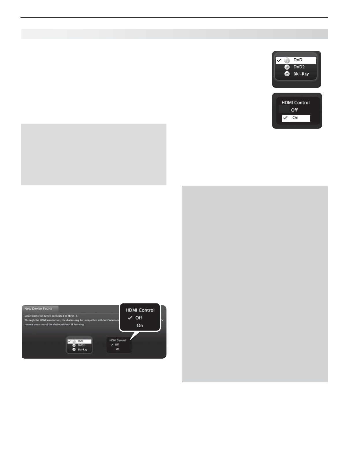
66 Appendices
Appendix C: HDMI Control of CEC Devices
Many new HDMI devices have a feature called Consumer Electronics Control (CEC) or HDMI Control.
HDMI Control allows one device, such as the TV, to
control other devices, such as an A/V receiver or disc
player. Use of CEC is optional.
Each manufacturer chooses which CEC functions to
support so it is difficult to predict which devices and
features are compatible with Mitsubishi’s HDMI Control.
You may find that CEC functions for a specific device are
limited.
To use HDMI Control, you must enable it in both
the TV and the device.
In the TV.• Enable HDMI control from the New
Device Found screen or from the Inputs > HDMI
Control menu.
I•
n the Device. Most devices with HDMI CEC com-
patibility let you turn it on or off in the device menus,
where it is typically listed as “HDMI Control.”
Enabling HD MI Control of CEC Devices
To ensure proper detection
Power on HDMI devices before connecting them to •
the TV.
Connect and set up HDMI devices one at a time.•
Power on the device and allow it to complete the
1.
power-on sequence (boot up). Stop any playback.
Connect the device to one of the TV’s HDMI inputs.
2.
When the TV detects the connection, the
3.
Device Found screen will appear.
Note: See “If the New Device Found Screen Displays
No HDMI Control Option” on this page if there is
no HDMI Control option.
New Device Found screen with HDMI Control option.
This screen displays only if the device’s HDMI Control is
enabled
.
New
If prompted for a name,
4.
highlight the name you want
to assign the device.
Highlight
5.
Highlight
7.
Device Found screen.
Note: At any time after completing Auto Input Sens-
On.
EXIT and press
ing, you can set the TV’s HDMI control on or off
in the Inputs > HDMI Control menu.
ENTER
to close the New
If the New Device Found Screen
Displays No HDMI Co ntrol Option
If the New Device Found screen shows no option for
HDMI Control, one of these conditions applies:
HDMI Control is turned off in the menus of the •
new device
Action:
Highlight a. EXIT and press
New Device Found screen.
Display the device’s setup menus and enable b.
the device’s CEC capabilities.
Wait for the TV’s c. New Device Found screen
to appear again.
If the d. New Device Found screen still has no
HDMI Control option, power off the device.
Power on the device and wait for the New
Device Found screen to display with the
HDMI Control option.
The device does not have CEC compatibility•
Action:
Control the device with its own remote control or program the TV’s remote control to
operate the device.
837 Series. - Use the TV’s NetCommand IR
control ( page 45 ).
ENTER
to close the
Page 67
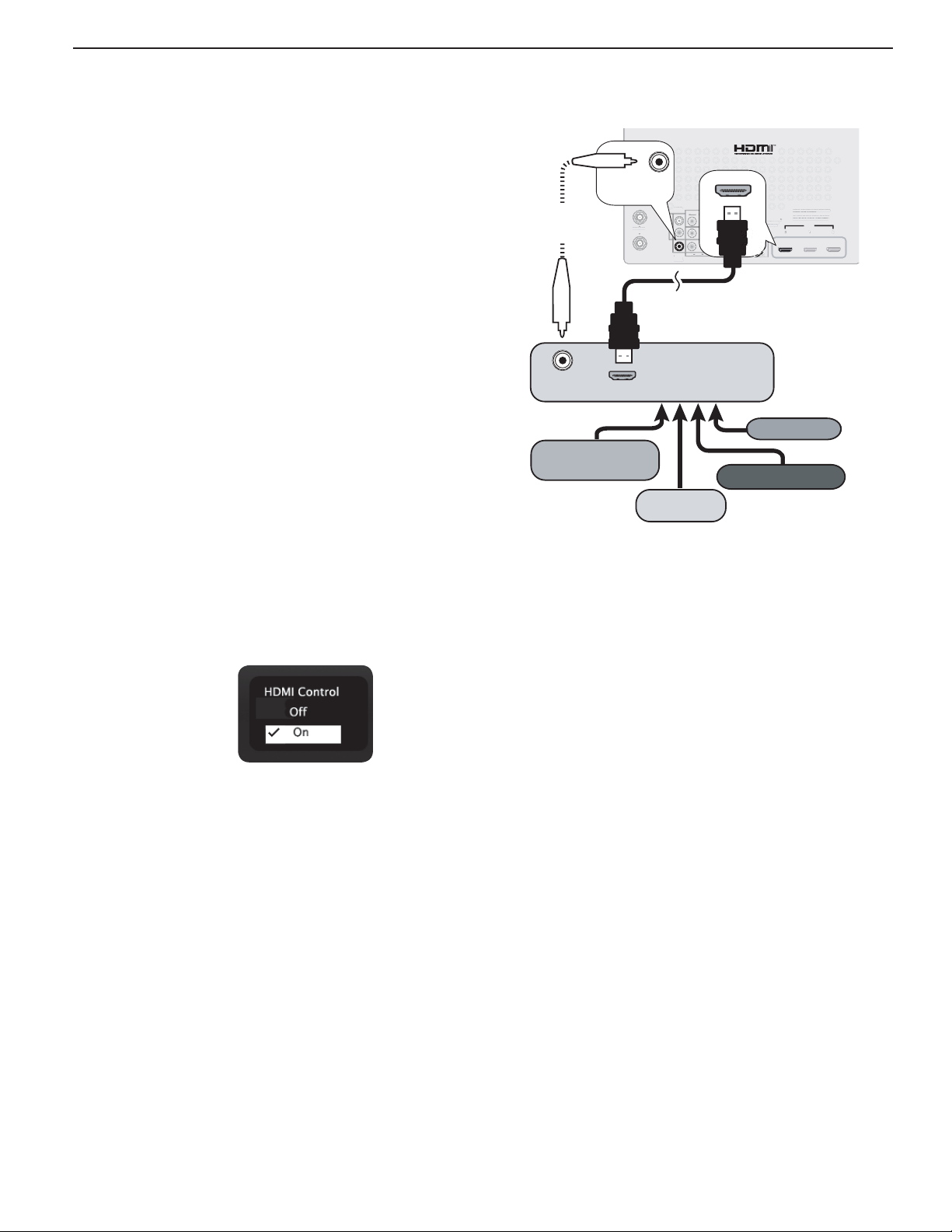
Appendices 67
HDMI
3
GLASSES
O
OUTPU
L
O
T
L
R
DVI/PC
AUD
V
p
AUDIO
P
X
HDMI
NetCommand
O
A
l
HDMI Control of an HDMI A/V
Receiver and Connected Devices
Note: Connect the A/V receiver to the TV before con-
necting any other device to the A/V receiver.
Enable HDMI Control for the A/V receiver as
1.
described in “Enabling HDMI Control of CEC
Devices” on the opposite page .
Power on the HDMI device you wish to connect to
2.
the A/V receiver (such as a disc player, cable box,
or satellite receiver). Allow the device to complete
the power-on sequence (boot up). Stop playback if
the device starts playing.
Connect the device to the A/V receiver with an
3.
HDMI cable.
Select the device’s HDMI input on the A/V receiv-
4.
er’s front panel controls or remote control.
When the TV detects the connection, the
5.
Device Found screen will appear.
Note: If the TV is unable to detect the device, either
the device’s CEC capability is not enabled or
the device is not CEC compatible. Enable
HDMI control through the device’s menus
before continuing. You may need to temporarily connect the device directly to the TV to view
device menus.
New
3D
D
GLASSES
EMITTER
DIGITAL
AUDIO
OUTPUT
Optional
digital audio
connection
ANT 2 / AUX
NT 2 / AUX
ANT 1 / MAIN
ANT 1 / MAIN
AVR
AUDIO
AUDI
OUTPUT
T
DVI/PC INPUT
L
AUDIO
R
VIDEO
L
R
AUDIO
L
R
L
R
AUDIO
AUDI
DIGITAL
DIGITA
DIGITAL
AUDIO
AUDIO
AUDIO
OUTPUT
OUTPUT
UTPU
Y
Y/ VIDEO
(480i / 480p / 720p / 1080i)
INPUT 3
Pb
Pb
IR-
NetCommand
Output / External
Controller Input
VIDEO: 480i/480p/720p/1080i/1080p
IDEO: 480i/480p/720p/1080i/1080
AUDIO: PCM STEREO
PC: VGA, W-VGA, SVGA, W-SVGA,
C: VGA, W-VGA, SVGA, W-SVGA,
R
XGA, W-XGA, SXGA, 720p/ 1080p
GA, W-XGA, SXGA, 720p/ 1080p
1
: PCM STEREO
HDMI
HDMI
HDMI
2
3
TV back pane
A/V receiver with
DIGITAL
AUDIO
OUTPUT
HDMI OUT
HDMI output
VCR
High-definition
DVD player
DVD player
Cable box
Connecting HDMI devices. The optional digital audio
connection allows you to hear audio through the A/V
receiver from devices connected to the TV only.
Highlight
6.
7.
Highlight
On.
EXIT and press
ENTER
to close the New
Device Found screen.
Optional: Connect the TV’s
8. DIGITAL AUDIO
OUTPUT
to an input on the A/V receiver. Use this
additional connection if:
You want the ability to switch between the A/V •
receiver speakers and the TV speakers.
You want to use the A/V receiver to listen to •
devices connected to the TV only, e.g., an
antenna input or camcorder.
837 Series.
9.
If desired, perform NetCommand IR
Learning to supplement CEC functions. You must
first connect and place IR emitters for the devices.
See page 45 .
Page 68
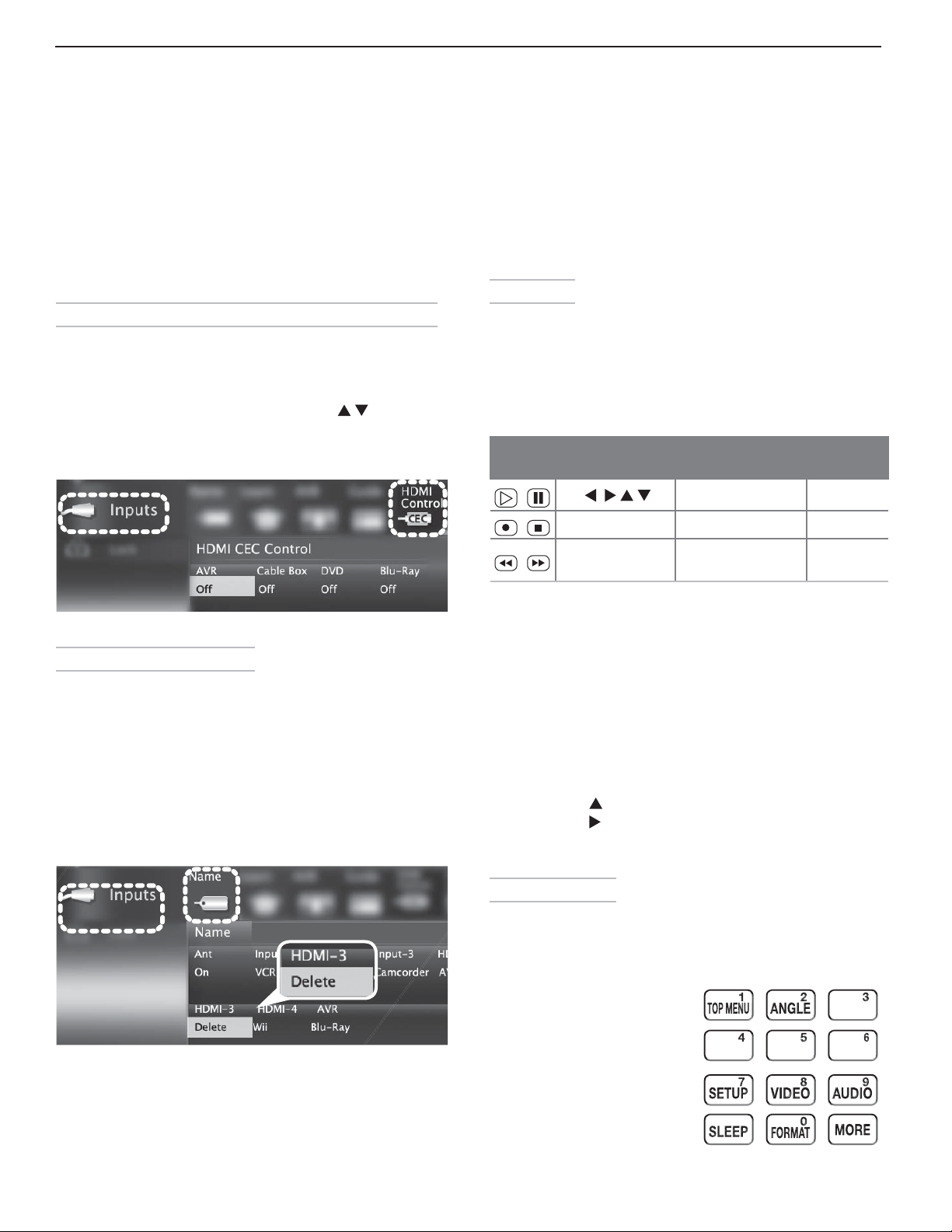
68 Appendices
Resolving CEC Conflicts
Because each manufacturer selects which CEC functions to support, some devices can conflict with other
devices. If control conflicts arise, you can:
Turn off TV control of an individual CEC-enabled •
device (see below).
Turn off CEC in the setup menu of one of the •
devices.
Turning Off the TV’s HDMI Control of a CEC Device
Press
1.
2.
3.
4.
MENU
on the TV remote control.
Highlight
to open the menu.
Move to the device name and press
Off to turn off the TV’s ability to control the device.
Press
Inputs > HDMI Control and press
MENU
to clear the menu.
ENTER
to select
Using H DMI Control
As an example of using HDMI Control, press
the device itself to:
Power on the TV•
Switch to the device (no need to display the •
Activity menu)
Begin play of the device•
Direct Keys
Test your equipment with the TV’s remote control to
find additional supported commands. See the table
below for commands that may be available, depending
on the individual device.
CEC-enabled VCR, DVD, and DVR functions that
may be available:
Record/
Playback
Menu
Navigation
ENTER
CANCEL
(to cancel)
Channel Tuning Other
CHANNEL UP/DN GUIDE
Digits
0–9, CANCEL MENU
ENTER
PLAY
on
Inputs > HDMI Control menu
Remo ving an HDMI Device
Power off the device.
1.
Disconnect the HDMI cable.
2.
Press
3.
4.
5.
6.
MENU
on the TV remote control to enter the
TV main menu.
Highlight
the menu.
Select
Press
Inputs > Name and press
Delete from the HDMI input names.
MENU
to clear the menus.
ENTER
to open
If you have a CEC-enabled A/V receiver, CEC-enabled
devices connected to the A/V receiver with an HDMI
cable may also be controllable. They can be selected
from the TV’s Activity menu.
CEC-enabled A/V receiver functions that may be
available:
Try the •
keys.
To open the A/V receiver menu, follow these steps:•
The MORE Menu
Press
of additional supported functions for the current
CEC-enabled device. To issue a command, press the
number key indicated in the menu.
VOLUME UP/DOWN, MUTE
While watching TV, press 1.
Press 2.
Press 3. to select AVR as the source.
Press 4.
menu.
MORE
until the Speakers option displays.
MORE
and then
on the TV’s remote control to see a menu
, and menu-navigation
MORE
then 9 (AUDIO).
1 (MENU)
to display the
Inputs > Name menu with Delete selected for HDMI-3.
MORE key: Sample menu for
a CEC-enabled DVD player
Page 69
Appendices 69
Appendix D: TV Care
La mp-Cartridge Replacement and Cleaning
CAUTION: If the television is on, press POWER to turn it off. Unplug the television and
allow it to cool for at least one hour before attempting to replace the lamp cartridge.
Lamp
The light source for this television is a
lamp, which is part of a lamp cartridge
assembly. The life of the lamp can
vary, based on the lamp itself, the air
temperature around the TV while it is
operating, the selected lamp mode, and
your viewing patterns. Warmer air or
poor ventilation shorten the lamp life,
as does use of the
and turning the television on and off
frequently. Mitsubishi warrants the lamp for one (1) year from the date of
original TV purchase at retail.
To Order a New Lamp
To Receive a Replacement Lamp Under Warranty
Visit our website at www.mitsuparts.com.•
Call (800) 553-7278. Please have model number, serial number, •
and TV purchase date available.
Important: All lamps replaced under warranty must be returned to
Mitsubishi where they will be inspected for defect verification.
Bright
lamp mode
tridge housing. Keep lamp cartridge horizontal during removal. Do
BURN DANGER! HOT SURFACES INSIDE!
Touch lamp cartridge handle only. Do not touch lamp or lamp car-
not tilt as glass may come out and cause injury. Replace lamp car-
tridge only with the same part number 915B403001.
CAUTION
WARNING
THE ACCESS PANEL IS
PROVIDED WITH AN INTERLOCK
TO REDUCE THE RISK OF
EXCESSIVE ULTRAVIOLET
RADIATION. DO NOT DEFEAT
ITS PURPOSE OR ATTEMPT TO
SERVICE WITHOUT REMOVING
PANEL COMPLETELY.
To Purchase a Replacement Lamp After Warranty
Visit our website at www.mitsuparts.com or call (800) 553-7278. Order the following:
Lamp Part Number 915B403001
Lamp-Substitution Alert
MDEA recommends that you use only genuine Replacement Lamp Assemblies purchased directly from Mitsubishi or a
Mitsubishi Authorized Dealer or Mitsubishi Authorized Service Center. MDEA advises that replacement lamps obtained
separately from the Lamp Cartridge and/or Lamp Assemblies obtained from unauthorized sellers may be incorrect for
your television, may not fit or perform properly and may even damage your television. MDEA can not be responsible
for the performance, reliability or safety of any replacement lamps that are obtained from unauthorized sources.
WARNING
• Do not remove the lamp cartridge immediately after turning off the television. You may get burned because the
lamp is very hot. Allow the television to cool for at least one hour before replacing the lamp cartridge.
• Do not remove the lamp cartridge except when replacing it. Careless treatment can result in injury or fire.
• Do not touch the lamp glass element. It may be very hot and break, causing injuries or burns.
•
Be sure not to insert any metal or flammable object into the lamp cartridge opening, as it may cause fire or electrical
shock. If a foreign object is inserted into the opening, unplug the AC cord of the TV and contact your dealer for service.
• Install the lamp cartridge securely. Failure to do so may cause a fire.
• Do not touch the lamp glass elements. Oils from your fingers may cause premature lamp failure.
THE LAMP INSIDE THIS PRODUCT CONTAINS MERCURY AND MUST BE RECYCLED OR
Hg
= MERCURY
DISPOSED OF ACCORDING TO LOCAL, STATE OR FEDERAL LAWS. For disposal or recycling information, please contact your local authorities or the Electronic Industries Alliance at
www.eiae.org
Page 70
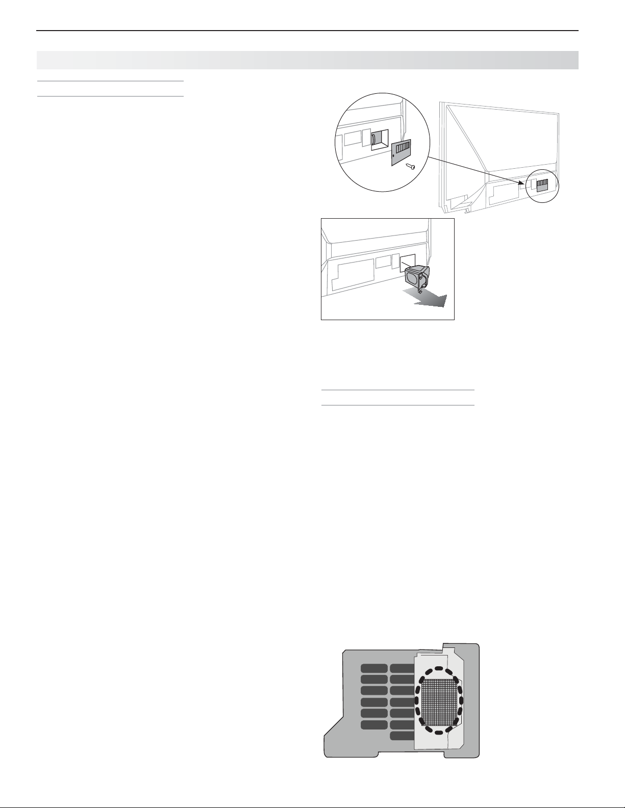
70 Appendices
Appendix D: TV Care, continued
Lamp-Cartridge Replacement
Removing the Old Lamp Cartridge
Turn off TV power and unplug the TV. Allow the
1.
lamp to cool for at least one hour before proceeding.
After the lamp has cooled, remove the cover of the
2.
lamp compartment, located on the back of the TV.
Refer to figures 1 and 2. Use a #2 (medium) Phillips
screwdriver to loosen the screw securing the cover.
Keep the screw and cover for re-installation
Wi
3.
th a medium Phillips screwdriver, loosen the two
screws securing the lamp cartridge until they disengage from the mating threads. These are captive
screws and cannot be separated from the lamp
cartridge.
Fully open the bag supplied with the replacement
4.
lamp and set the opened bag aside.
Gently grasp the handle of the lamp cartridge and
5.
pull the old cartridge straight out. See figure 3.
CAUTION: Do not tilt or rotate the cartridge, as
small glass fragments may fall out.
Without tilting or putting down the lamp cartridge,
6.
insert it into the opened bag. Close the bag while
being careful not to let any glass particles fall out.
Installing the New Lamp Cartridge
Do not touch the glass parts of the new lamp car-
1.
tridge. Insert the new cartridge into the TV in the
same orientation as the old cartridge. Push on the
cartridge housing until it is fully seated.
Gently tighten the screws with the screwdriver.
2.
AVOID OVERTIGHTENING!
Replace the plastic cover and retaining screws.
3.
WASH YOUR HANDS THOROUGHLY, AS THIS
4.
LAMP CONTAINS MERCURY.
Disposal of the Old Lamp Cartridge
Lamp under warranty: All lamps replaced under warranty must be returned to Mitsubishi. Use the return
shipping label provided and send to Mitsubishi Digital
Electronics, America, 625 Braselton Parkway, Suite 200,
Braselton, GA 30517.
Figure 1
Figure 2
Figure 3
Use only replacement lamp part number
915B403001.
Lamp-Cartridge Filter Cleaning
If the TV shuts off after displaying the message “TV
will shut down in a few seconds. Please check if the
air flow is blocked” and/or the
air filter may need cleaning. The air filter is part of the
lamp cartridge. Use the following procedure to clean
the filter.
Remove the lamp cartridge from the TV as
1.
described under “Removing the Old Lamp Cartridge.” Do not tilt or rotate the cartridge. Do not
touch the glass parts of the lamp cartridge.
Holding the lamp cartridge horizontal (do not tilt or
2.
rotate), use a soft dry brush or vacuum cleaner to
remove any dust that may be present on the mesh
filter. Do not use liquids. See figure 4.
Reinstall the lamp cartridge as described under
3.
“Installing the New Lamp Cartridge.”
STATUS
LED is yellow, the
IMPORTANT: Lamps found to be without defect will
be returned and charged back to the sender.
Lamp no longer under warranty:
local authorities or the Electronic Industries Alliance at
www.eiae.org for lamp-disposal or recycling instructions.
Do not dispose of the old lamp with common trash.
Contact your
Figure 4
Keep lamp
cartridge horizontal
and remove dust
from the mesh filter
using a vacuum
cleaner or soft dry
brush.
Page 71

Appendices 71
Appendix D: TV Care, continued
Cl eaning Recommendations
Normally, light dusting with a dry, non-scratching duster
will keep your TV clean. If cleaning beyond this is
needed, please use the following guidelines:
First, turn off the TV and unplug the power cord from
the power outlet.
Occasionally clean dust build-up from the air-intake
grilles on the back and sides of the TV. Clean using a
vacuum cleaner with a brush attachment.
Top and Sides of the TV
Gently wipe down your TV with a soft, non-abrasive •
cloth such as cotton flannel, microfiber, or a clean
cloth diaper, lightly moistened with water. Dry with
a second dry, soft, non-abrasive cloth.
For oily dirt, add a few drops of mild liquid deter-•
gent, such as dishwashing detergent, to the water
used to moisten the cloth. Rinse with a second
cloth moistened only with water. Dry with a third
dry, soft, non-abrasive cloth.
Screen
Follow the instructions for the top and sides, wiping •
gently in an up and down motion.
Clean the entire screen evenly, not just sections of •
the screen.
Do not allow liquid to drip down the screen, as •
some liquid may enter the TV through the gap
between the screen and screen frame.
You may purchase Mitsubishi Screen Cleaner, part •
number CLEANER-VSS, by calling (800) 553-7278.
Care of the Remote Control
Remote Control Tips
For longer life, use alkaline batteries.•
Do not mix old and new batteries.•
Be within 20 feet of the equipment.•
Do not press two or more keys at the same time •
unless instructed to do so.
Do not allow the unit to get wet or become heated.•
Keep the unit out of direct sunlight.•
Avoid dropping on hard surfaces.•
Do not use harsh chemicals to clean. Use only a •
soft, lightly moistened cloth.
Resetting the Remote Control
If
TV
mode is selected and the TV does not respond
properly, reset the remote control.
Press and hold
1.
mode indicator blinks twice and goes off.
Release the
2.
Press keys
3.
blink twice when you finish entering the code.
When entering the code, pause for a moment
between each key press to ensure it is recognized.
Low-Battery Indicator
If you press a key and the mode indicator blinks five
times, replace the remote control’s batteries.
POWER
for several seconds until the
POWER
key.
0 0 9 3 5
and the mode indicator will
General Cleaning Precautions
DO NOT allow liquid to enter the TV through the •
ventilation slots or any crevice.
DO NOT use any strong or abrasive cleaners, as •
these can scratch the surfaces.
DO NOT use any cleaners containing ammonia, •
bleach, alcohol, benzene, or thinners, as these can
dull the surfaces.
DO NOT spray liquids or cleaners directly on the •
TV’s surfaces.
DO NOT scrub or rub the TV harshly. Wipe it gently.•
Page 72
72 Appendices
Appendix E: Troubleshooti ng
ANT
TV Reset Comparison Guide
You can resolve many common TV problems using
the reset functions described in the following table.
See also the troubleshooting suggestions later in this
appendix.
IMPORTANT
Before you change sound or picture settings: If
picture or sound settings seem wrong for a broadcast
Reset Name When to Use How to Use Resulting Action
channel (a channel from the
satellite receiver), first check other channels from the
same input before changing settings. If most other
channels from the same input seem correct, there is
likely a problem with the broadcast rather than with the
TV. Use care in this case, as changes you make to fix
problems on individual channels also affect all other
channels on the same input.
input, a cable box, or
Format When the picture
shape seems
incorrect, use
PerfectColor
Reset
or
PerfectColor™/
PerfecTint™
Reset (837
Series)
(for the single
input currently
being watched)
A/V Memory
Reset
(for the single
input currently
being watched)
™
MORE > 0
change the shape of
the picture.
When the color
intensities seem out
of balance, use the
PerfectColor/PerfecTint
reset to reset the color
balances to the original
factory settings.
Both PerfectColor and
PerfecTint are reset at
the same time.
When audio and/
or video settings for
a single input seem
incorrect, use A/V
Memory Reset to
return the input to
the original factory
settings.
(FORMAT) to
MORE
Press the
edly press
through the available aspect ratios.
While viewing the input to 1.
be reset, press
go to Adjust > Picture+ >
PerfectColor.
Press 2.
PerfectColor adjustment screen.
Press 3.
While viewing the input to reset, 1.
press
Reset.
Press 2.
Reset icon.
Press 3.
key and then repeat-
0
(FORMAT) to cycle
MENU
and
ENTER
to display the
CANCEL
MENU
ENTER
ENTER
to reset the colors.
and go to Adjust >
to highlight the
again to reset.
The last-used format for a signal
type is memorized for each input.
The next time the same input and
the same signal type is viewed,
the last-used format will be
recalled.
All PerfectColor/PerfecTint
sliders are reset to the original
center position. The PefectColor/
PerfecTint settings for other
inputs remain unchanged.
All Audio and Video settings
for the individual input are
reset except for the Listen To,
Language, audio Balance,
Closed Caption, and Advanced
Picture settings.
Service and Customer Support
Service
If you are unable to correct a problem with your TV,
consult your Mitsubishi dealer or Mitsubishi Consumer Relations at (800) 332-2119.
• DO NOT adjust any controls other than those
described in this Owner’s Guide.
• DO NOT remove the protective back cover of
your TV.
Customer Support
• To order replacement or additional remote controls or lamp cart
mitsuparts.com or call (800) 553-7278.
• For questions:
Important
All lamps replaced under warranty must be returned
to Mitsubishi where they will be inspected for defect
verification.
ridges,
visit our website at www.
Page 73

Appendices 73
Appendix E: Troubleshooting, continued
Reset Name When to Use How to Use Resulting Action
A /V Reset
(for all inputs)
Channel
Memorization
Lock Menu
Pass Code
Control-Panel
Lock Release
Auto Input
Sensing for
HDMI
To reset audio and
video adjustments for
all inputs to the original
factory settings.
To erase and
re-memorize channels
on the
To change your Lock
menu pass code
To re-enable the
control-panel buttons
after activation of the
Control-Panel Lock
When connecting an
HDMI device does
not trigger Auto Input
Sensing.
ANT
input.
While viewing the TV, press the
control-panel buttons
VOLUME DOWN
While viewing the TV, press 1.
MENU
Navigate to the 2. Initial> Channel
menu.
Press 3.
Highlight the reception mode, 4.
e.g. Ant Air.
Highlight 5. Scan.
Press 6.
memorization.
See the
page 57 .
Press and hold the
on the control panel for over eight
seconds. This works even if the TV
is powered off.
Disconnect the HDMI device.1.
Delete the HDMI input in the 2.
Inputs > Name menu (see page
40 ).
Power on and connect the new 3.
device.
at the same time.
to display the main menu.
ENTER.
ENTER
cutout page from Appendix A ,
ACTIVIT Y
to start channel
ACTIVIT Y
and
button
All Audio and Video settings are
returned to the original factory
settings, including Listen To,
Language, audio Balance,
Closed Captions, Format and
Advanced Picture settings.
All previously memorized channels for the antenna input are
erased and a new set of memorized channels is created. To add
or delete individual channels, see
Initial > Channel > Edit menu
instructions on page 39 .
Allows establishment of a new
code.
Allows the control panel to be
unlocked if the remote control is
misplaced.
The New Device Found screen
will display.
System Reset If the TV does not turn
on or off, does not
respond to the remote
control or controlpanel buttons, or has
audio but no video.
TV Reset
IMPORTANT:
Use this reset
only if all other
resets have been
unsuccessful.
To reset all consumeraccessible settings
and all memories to
the original factory
defaults.
CAUTION: All ownerperformed setups and
adjustments will be
erased.
Press and hold the
the control panel for ten seconds.
While viewing the TV, press 1.
MENU
to display the TV main
menu.
With the main menu displayed, 2.
press number keys 1 2 3 to
display the Reset menu.
READ THE ON-SCREEN 3.
WARNING AND INSTRUCTIONS.
If you do not wish to use this •
reset, press
back out.
If you do wish to use the •
reset, press
all memories and settings.
POWER
BACK
ENTER
button on
or
MENU
to erase
The TV will turn off and the green
LED will flash quickly for about
one minute. When the green
LED stops flashing, you may turn
on the TV. The changes you
made most recently, before using
SYSTEM RESET
The TV will start the initialization
process. The TV will then turn
off and the front green LED will
start flashing. When the LED
stops flashing, you can turn on
the TV again. All memory and
settings outlined in this Owner’s
Guide will need to be set again.
to
, may be lost.
Page 74
74 Appendices
Appendix E: Troubleshooting, continued
General TV Operation
Symptom Remarks
1. A fan is running even while the TV is powered
off.
2.
The fan gets louder after the TV is shut off.
3.
The TV remote control does not work. Check that the batteries are fresh and installed correctly.•
4.
When I try to use the remote control, the
POWER key blinks five times.
5.
TV does not respond to the remote control or
to control-panel buttons and TV will not power
on or off.
6.
When a device is selected from the Activity
menu, the screen is blue or black (no signal
source).
7.
You have forgotten your Lock menu pass code. See “Bypassing the Parental Lock” , Appendix A .
8.
Rating restrictions are not working.
9.
On-screen displays appear each time you
change a function.
10. A warning message appeared on screen
stating, “TV will shut down in a few seconds.
Please check if the air flow is blocked.”
I have turned on CEC for my HDMI devices but
11.
control is erratic and I wish to disable it.
The room is too warm. When the TV is off, internal components
continue to draw power and must be cooled by the fan.
Normal operation. The fan speeds up to cool the lamp quickly
after the TV has been shut off.
Check that the control mode on the remote is set to TV.•
Be no more than 20 feet from the TV when using the remote control.•
Program the remote control to operate the TV or other device.•
Reset the remote control.•
Replace the batteries.
Unplug the AC power cord for 10 seconds.•
Press and hold the POWER button on the control panel to •
perform system reset.
• Make sure the selected device is turned on.
• Begin play of the device.
Open the Lock > Parental Lock menu and:
• Verify that the ratings locks are active.
• Check the Lock Time/Unlock Time to check if rating restrictions are disabled.
• Rating restrictions apply only to content on the ANT input.
Normal TV operation.
• Internal TV temperature has exceeded proper levels. Cool
the room.
• The TV has overheated. Clear blocked air vents and ensure
at least four inches of clearance on all sides of the TV.
• Clean the air filter on the lamp cartridge.
First •
turn off the TV’s HDMI control for the specific device. Open
the Inputs > HDMI Control menu, select the device, select Off.
Disable CEC on the device itself. See the device’s instructions.•
If the problem persists, do the following:•
Disconnect the device from the TV.1.
Reconnect the device to the TV and Auto Input Sensing will 2.
recognize the device with CEC disabled.
Page 75
Appendices 75
Appendix E: Troubleshooting, continued
TV Channels
Symptom Remarks
1.
The TV takes several seconds to respond to
channel changes.
2.
You cannot access a channel.
3. When ChannelView list is displayed, informa-
tion appears incomplete
It is normal for digital channels to take longer to tune in.•
Press ENTER after entering a channel number to avoid •
delays.
Use a 4-digit number for an over-the-air digital channel.•
Use a 6-digit number for digital cable channels if your cable •
service is able to recognize 6-digit channel numbers.
Use number keys instead of CHANNEL Up/Down.•
Be sure the channel you want to view is in memory.•
Check that the TV is switched to the correct device or •
antenna for that channel by pressing the ACTIVITY key.
Make sure the Lock > Parent menu lock is set to Off.•
If you cannot tune to a virtual digital channel even though the •
TV has already memorized digital channels, tune to the physical channel number used by the broadcaster. The virtual
channel will then be automatically added to memory.
You may be trying to tune to an analog channel that is no •
longer broadcasting.
Press INFO to update the display for the highlighted channel.•
Program information is displayed only for the currently tuned •
channel.
Available information is sent from the broadcaster or cable •
provider. No other data is available.
Make sure the TV clock is set correctly.•
TV Power On/Off
Symptom Remarks
1. TV takes an excessively long time to power
on.
2. You cannot program the TV to turn on auto-
matically (Timer function)
3. TV turned itself off and the light on the front
panel started to blink.
4. TV will not power off. Press the POWER button on the control panel for ten seconds
When powered on, the TV needs time to boot up, just as a computer does. Also, the TV’s lamp requires a few moments to heat
up to full brightness.
The TV may be locked.•
The clock may not be set.•
Momentary power fluctuation caused the TV to turn off to •
prevent damage. Wait for the green light to stop flashing
and turn the TV on again.
If the TV does not stay on, press the POWER button on the •
control panel for at least eight seconds to perform System
Reset. If this happens frequently, obtain an AC line power
conditioner/surge protector.
An unusual digital signal may have been received, triggering a •
protection circuit. Wait for the light to stop flashing and turn TV
on.
to perform System Reset.
Page 76
76 Appendices
Appendix E: Troubleshooting, continued
Picture
Symptom Remarks
1. Picture does not look like a high-definition
picture.
2. TV has sound but no picture. Check that all video inputs are plugged in firmly.•
3. Picture has become dimmer. • The lamp is nearing the end of its life. Order a new lamp.
4. There is a large black or gray rectangle on
the screen.
5. You cannot view a picture when playing a
VHS tape.
6. VCR or DVD player’s on-screen menus jitter
up and down.
7. When viewing a stopped VCR, white lines
are rolling on the screen.
8. A color program appears as a black and
white image, or the colors are dim, or the
screen is black.
9. Picture from an HDMI input is noisy (poor
quality).
10. The image from a computer appears dis-
torted when viewed on the TV.
Not all signals are high-definition signals. To receive high-definition programming from your cable or satellite provider, you must
subscribe to the provider’s high-definition service. Some overthe-air broadcasts are in high-defi nition and can be received with
a high-quality antenna suited to your location.
Press and hold the POWER button on the control panel for •
ten seconds to perform System Reset.
• Adjust picture brightness and contrast to maximum levels.
• Change Lamp Energy from Standard to Bright.
The TV’s analog closed captioning has been set to “text” mode
in the Captions menu. Turn off because there is no text information being broadcast.
Check your VCR’s owner’s guide for further troubleshooting.
Stop playback. Possible cause: Many VCRs and DVD players
provide on-screen menus at only half-resolution that may
appear to jitter up and down.
• Turn off video mute for the VCR.
• Begin playing the tape.
• Change the VCR input from Line 1 to the VCR antenna input.
The PerfectColor color balance has been incorrectly set. Reset
the PerfectColor balance.
Upgrade a Category 1 (unmarked) HDMI cable to a Category 2
high-speed HDMI cable.
Normal TV operation. The TV does not correct distortion in •
the picture from a computer because the correction process
may cut off the edges of the image.
The aspect ratio may be wrong for the image. Press MORE •
and then 0 (FORMAT) to change.
Sound
Symptom Remarks
1. There is no sound even when the
volume is turned up.
• Check if the MUTE key is on.
• The TV’s “Listen to:” setting may be set to SAP (analog program
from the ANT input).
• Check that the Speakers option is set to TV to hear sound from the
TV speakers. Sound may be being sent to one of the audio outputs
for an A/V receiver or headphones.
• If using an A/V receiver, check that the Speakers option is set to AV
Receiver to hear sound from the A/V receiver speakers.
•
Press and hold the POWER button on the control panel for 10
seconds to perform System Reset.
Page 77

Appendices 77
Appendix E: Troubleshooting, continued
Sound
Symptom Remarks
2. The sound does not match the screen
picture.
3. The sound from my A/V receiver does
not match the screen picture (I should
hear the correct audio from my A/V
receiver).
4. Cannot select an audio-only device; it
does not appear in the Activity menu.
The TV’s “Listen to:” setting may be set to SAP
the ANT input)
Check that DIGITAL AUDIO OUTPUT and/or AVR AUDIO •
OUTPUT on TV’s main panel is connected to the A/V receiver.
Without this connection, devices connected only to the TV (and
not the A/V receiver) can be heard only from the TV speakers.
Note that this includes the ANT input, a device (such as a
camcorder) connected to the convenience panel, and any other
device sending audio to the TV only.
If using a NetCommand-controlled A/V receiver, NetCommand •
may be selecting the wrong A/V receiver audio input. Check the
A/V receiver’s NetCommand setup in the Inputs > AVR menu.
If playing MP3 files from a USB device, check that the TV’s audio •
output is connected to the A/V receiver.
Plug an unused video plug into the
Input Sensing and make the audio device selectable in the Activity
menu.
.
Y/V I D EO
(analog program from
jack to activate Auto
N etCommand IR Control (NetCommand-equipped models only)
Symptom Remarks
1. Cannot see the menu from the A/V Receiver. A/V Receiver Set Up for Audio-Only Switching•
The A/V Receiver is not connected to any video input of the
TV. To check the A/V Receiver menu, temporarily plug into
an unused input of the TV, such as Input 3. Exit the New
Device Found screen and select Input 3 from the Activity
menu. Press MENU on the A/V receiver’s remote control.
A/V Receiver Set Up for Audio and Video Switching over •
HDMI
Use the MENU key on the A/V receiver’s remote control.
A/V Receiver with • HDMI Control
Switch the remote control to AUDIO mode. Press the
MORE key and then 1 (Menu).
2. NetCommand unable to learn specific device
keys.
A/V Device does not use IR format for remote control •
signal. ITT and RF formats cannot be learned.
Room lighting may affect the signal. Have the remotes very •
close (6 inches or less) to the TV during Learning.
If learning a Mitsubishi remote control, make sure mode is •
not set to TV.
Some, but not all, device key functions can be learned by •
NetCommand. For example, POWER and PLAY may be
learned, but other functions may not.
The signal from the remote control may not be strong •
enough. Insert fresh batteries and try Learning again.
Page 78
78 Appendices
Appendix E: Troubleshooting, continued
N etCommand IR Control (NetCommand-equipped models only)
Symptom Remarks
3. The A/V receiver is the selected audio source
but there is no sound.
4. There is no sound from the A/V receiver
for my DVD player or other surround sound
device even though I learned the IR code for
the A/V receiver’s DVD input or other input.
(A/V Receiver Set Up for Audio-Only Switching)
5. There is no sound or picture from the A/V
receiver for my DVD player or other device
connected to the A/V receiver; the A/V
receiver should be sending video to the TV
over an HDMI cable.
(
A/V Receiver Set Up for Audio and Video
Switching over HDMI)
6. I’ve selected my DVD player or other sur-
round sound device in combination with the
TV speakers but hear no sound from the TV
speakers.
7. I “learned” the RECORD key for my VCR/DVR
but when I pressed the RECORD key, the
VCR/DVR did not record anything.
A/V Receiver Set Up for Audio-Only Switching•
Check to see if the A/V Receiver power is turned on. With A/V receiver power turned on, redisplay the Activ- ity menu and press ENTER to allow NetCommand to
correctly select the A/V Receiver input.
Incorrect setup in the Inputs > AVR menu. Check the device connection assigned in the AVR menu.
A/V Receiver Set Up for Audio and Video Switching over HDMI•
Check to see if the A/V Receiver power is turned on. If the device is connected only to the TV (e.g., on ANT or a front panel input), verify that the TV’s AUDIO
OUTPUT is connected to the A/V receiver.
The A/V receiver is not switching properly because you have not learned the IR codes for the A/V receiver
inputs to which your devices are connected.
NetCommand A/V receiver setup for the DVD player or digital
surround sound device or other device is not switching properly. See the owner’s guide and perform A/V receiver setup for
a digital surround sound device.
NetCommand A/V receiver setup is not switching audio and
video inputs properly. See the owner’s guide.
A/V Receiver Set Up for Audio-Only Switching•
If you have only an audio connection from the device to the
A/V receiver, a physical audio connection from the device
to the TV is also required.
Connect the left and right audio output from the device to the appropriate TV audio input. Now you can hear
audio from the device through either the TV speakers or
the A/V receiver.
To switch audio sources, press MORE 9 (Audio), press -
to show the Speakers option, then press to
select AV Receiver or TV.
A/V Receiver Set Up for Audio and Video Switching over HDMI•
With your DVD player connected to the A/V receiver, only
video is passed from the A/V receiver to the TV because of
copy-protection restrictions on the HDMI signal
Check that the VCR or DVR is receiving a signal directly from
your cable box or satellite receiver.
Page 79

Trademark and License Information 79
Trademark and License Information
LICENSOR’S SUPPLIERS DO NOT MAKE OR PASS ON TO END USER OR ANY OTHER THIRD PARTY, ANY
EXPRESS, IMPLIED OR STATUTORY WARRANTY OR REPRESENTATION ON BEHALF OF SUCH SUPPLIERS,
INCLUDING, BUT NOT LIMITED TO THE IMPLIED WARRANTIES OF NON-INFRINGEMENT, TITLE, MERCHANTABILITY OR FITNESS FOR A PARTICULAR PURPOSE.
®
Digital Light Processing
Manufactured under license from Dolby Laboratories. Dolby is a trademark of Dolby Laboratories.
™
HDMI
Licensing LLC.
The software in this TV is based in part on the work of the Independent JPEG Group, copyright © 1991-1998, Thomas
G. Lane, all rights reserved.
x.v.Color and the x.v.Color logo are trademarks of Sony Corporation.
ChannelView™, DeepField™ Imager, Easy Connect™, Net Command®, PerfectColor™, PerfecTint™, Plush 1080p®
5G, SharpEdge™, Smooth120Hz™ are trademarks of Mitsubishi Digital Electronics America, Inc.
the HDMI logo and High-Definition Multimedia Interface are trademarks or registered trademarks of HDMI
and DLP® are registered trademarks of Texas Instruments.
Page 80

80 Trademark and License Information
Mitsubishi TV Software
END-USER LICENSE AGREEMENT FOR EMBEDDED SOFTWARE
IMPORTANT – READ CAREFULLY: This License Agreement is a legal agreement between you (either an individual or an entity) and
Mitsubishi Digital Electronics America, Inc. (MDEA) for all software pre installed and/or provided along with this television (“Software”). By
utilizing this television and Software, you agree to be bound by the terms of this License Agreement.
The Software is protected by United States copyright laws and international treaty provisions, as well as other intellectual property laws
and treaties. The Software is licensed, not sold.
1. LICENSE GRANT. MDEA grants you a non-exclusive, non-transferable, limited right and license to use one copy of the Software
only with the Mitsubishi television model that included this owner’s guide and owned by you.
2. RIGHTS AND LIMITATIONS.
Software Not for Resale. You may not resell or otherwise transfer for value the Software, except in conjunction with a sale of the TV that
Software has been pre installed.
Prohibition on Reverse Engineering, Decompilation and Disassembly. The Software contains trade secrets or other proprietary material
in its human perceivable form and to protect them, you may not reverse engineer, decompile, or disassemble, or otherwise reduce the
Software to any human perceivable form, except to the extent that the foregoing restriction is expressly prohibited by applicable law.
Separation of Components. The Software is licensed as a single product. Its component parts may not be separated for use on more
than one TV.
No Rental. You may not rent, lease, lend, or sublicense the Software.
Trademarks. This License Agreement does not grant you any rights to any trademarks of MDEA.
3. VIOLATIONS. You understand that any use, copying or transfer of the Software, except as permitted pursuant to this License,
may subject you to serious criminal and civil penalties including damages and an award to MDEA of attorneys’ fees in connection with any
violation of this License. You further understand that you may be held legally responsible for any copyright infringement or other violation
of intellectual property rights that is caused, encouraged, or induced by your failure to abide by the terms of the License. This license
is effective until terminated, and will terminate immediately without notice from MDEA or judicial resolution if you fail to comply with any
provision of this License.
4. COPYRIGHT. All title and intellectual property rights in and to the Software (including but not limited to any images, photographs,
animations, video, audio, music, text, and “applets” incorporated into the Software), and any accompanying printed materials are owned
by or licensed to MDEA. All title and intellectual property rights in and to the content which may be accessed through use of the Software
is the property of the respective content owner and may be protected by applicable copyright or other intellectual property laws and
treaties. This License Agreement grants you no rights to use such content, except that you own the media on which the Software is
recorded, but MDEA and its licensors retain ownership of the Software itself. All rights not expressly granted are reserved by MDEA.
5. EXPORT RESTRICTIONS. MDEA is licensing the Software for use within the United States. You agree that you will not
export or re-export the Software. You specifically agree not to export or re-export the Software: (i) to any country to which the U.S. has
embargoed or restricted the export of goods or services, which currently include, but are not necessarily limited to Cuba, Iran, Iraq, Libya,
North Korea, Sudan, and Syria, or to any national of any such country, wherever located, who intends to transmit or transport the Software
back to such country; (ii) to any person or entity who you know or have reason to know will utilize the Software in the design, development,
or production of nuclear, chemical, or biological weapons; or (iii) to any person or entity who has been prohibited from participating in
U.S. export transactions by any federal agency of the U.S. government. You warrant and represent that neither the BXA nor any other U.S.
federal agency has suspended, revoked, or denied your export privileges.
6. DISCLAIMER OF WARRANTY. EXCEPT AS OTHERWISE PROVIDED IN THIS LICENSE OR IN THE LIMITED WARRANT Y
APPLICABLE TO THE TV, MDEA MAKES NO OTHER WARRANTIES OF ANY KIND WHATSOEVER REGARDING THE SOFTWARE
AND HEREBY EXPRESSLY DISCLAIMS ALL WARRANTIES OF ANY KIND WHATSOEVER, EXPRESS OR IMPLIED, WITH
RESPECT TO THE SOFTWARE. ALL IMPLIED WARRANTIES, INCLUDING, WITHOUT LIMITATION, THE IMPLIED WARRANTIES
OF MERCHANTABILITY AND FITNESS FOR A PARTICULAR PURPOSE ARE HEREBY EXPRESSLY DISCLAIMED BY MDEA . IN
NO EVENT SHALL MDEA BE LIABLE TO YOU OR ANY THIRD PARTIES, IN CONTRACT, IN TORT OR OTHERWISE, FOR ANY
DIRECT, INDIRECT, SPECIAL, INCIDENTAL OR CONSEQUENTIAL DAMAGES OF ANY KIND OR NATURE. BECAUSE SOME
JURISDICTIONS DO NOT ALLOW THE EXCLUSION OR LIMITATION OF IMPLIED WARRANTIES, THE ABOVE LIMITATION MAY
NOT APPLY TO YOU.
7. LIMITATION OF LIABILITY. MDEA SHALL NOT, UNDER ANY CIRCUMSTANCES BE LIABLE TO YOU OR ANY THIRD
PARTIES FOR ANY DAMAGES OF ANY NATURE, WHETHER INDIRECT, SPECIAL, INCIDENTAL, CONSEQUENTIAL OR
OTHERWISE, INCLUDING, BUT NOT LIMITED TO, ANY CL AIMS FOR LOST PROFITS, LOSS OF GOOD WILL OR EXPENDITURES
MADE OR COMMITTED FOR IN RELIANCE ON THE CONTINUATION OF THIS LICENSE. YOU AGREE THAT NEITHER MDEA’S
BREACH OF THIS LICENSE NOR ITS FAILURE TO REPAIR A DEFECT, ERROR OR BUG SHALL CONSTITUTE A FAILURE OF THE
ESSENTIAL PURPOSE OF THIS LICENSE. BECAUSE SOME JURISDICTIONS DO NOT ALLOW THE EXCLUSION OR LIMITATION
OF LIABILITY FOR CONSEQUENTIAL OR INCIDENTAL DAMAGES, THE ABOVE LIMITATIONS MAY NOT APPLY TO YOU. MDEA’s
liability to you for direct damages for any cause whatsoever and regardless of the form of the action, will be limited to the money
paid by you for the TV (based on fair market value of the TV) that caused the damages.
8. GENERAL. This License Agreement will be governed by the laws of the State of California.
WARNING: This product contains chemicals known to the State of California to cause cancer and/or birth defects
or other reproductive harm.
Page 81

Warranty 81
Mi tsubishi DLP Projection Television Limited Warranty
MITSUBISHI DIGITAL ELECTRONICS AMERICA, INC. (“MDEA”) warrants as follows to the original purchaser of this
television from an authorized MITSUBISHI Audio/Video Dealer, should it prove defective by reason of against defects
arising from improper workmanship and/or material:
a. Parts. The lenticular (i.e. front picture) screen is warranted against defects in materials and workmanship for a
period of thirty (30) days from the date of the original purchase at retail. The lamp and all other parts (except any software incorporated into this television) are warranted for a period of one (1) year from the date of the original purchase
at retail. We will repair or replace, at our option, any defective part without charge for the part. Parts used for replacement may be replaced with those of like kind and quality and may be new or remanufactured. Parts used for replacement are warranted for the remainder of the original warranty period.
b. Embedded Software. MDEA warrants that all software incorporated into this television set (the “Embedded
Software”) will perform in accordance with the functional description of Embedded Software in all material respects,
but MDEA does not warrant that the Embedded Software is error-free. The limited warranty contained in this section
shall continue for a period of one (1) year from the date of the original purchase at retail. If, after prompt notice within
the warranty period, MDEA determines that the Embedded Software has failed to perform in accordance with such
functional description in all material respects and if such failure is not due to accident, misuse, modification or misapplication of the Embedded Software, then MDEA shall modify or replace the nonconforming Embedded Software at
no charge to you, which at MDEA’s sole discretion may be fulfilled by means of modification or replacement software
contained on a replacement memory card for Customer installation. The foregoing shall be MDEA’s sole obligation
to you under this limited warranty. All rights under this limited warranty on the Embedded Software also subject to
your acceptance of and compliance with the terms of the Software License Agreement applicable to this television,
and this limited warranty on the Embedded Software shall be null and void if the Embedded Software is modified or
changed in any manner except as specifically authorized by MDEA.
c. Labor. For thirty (30) days after the original purchase at retail, we will repair or replace, at our option, the lenticular screen if it proves defective. For certain items that are designed to be replaced by the consumer, including (but
not limited to) some Embedded Software, the consumer is solely responsible for any replacement labor. For all other
parts, we will provide the labor for a warranty repair by an authorized MITSUBISHI service center without charge for
one (1) year from the original date of purchase at retail.
d. Notice. To obtain warranty service, you must notify an authorized MITSUBISHI service center of any defect within
the applicable warranty time period.
e. This DLP Projection Television uses a single DLP chip to create the screen image. This technology creates the
image using small dots, or picture elements (pixels). Your DLP Projection TV is manufactured to a high level of performance and quality, in fact, 99.99% perfect in the number of properly functioning pixels. As in other display technology, sometimes a pixel is continuously active, inactive or the incorrect color. Our standard is clear; MDEA warrants
only that the percentage of properly functioning pixels will be not less than 99.99% of all pixels.
BEFORE REQUESTING SERVICE, please review the instruction booklet to insure proper installation and
correct customer control adjustment. If the problem persists please arrange for warranty service.
1. TO OBTAIN WARRANTY SERVICE:
a. Contact your nearest authorized MITSUBISHI service center, whose name and address can be obtained from your
MITSUBISHI dealer, by writing at the address provided below, calling MDEA at the 800-332-2119, or by using the
support feature of our website at www.Mitsubishi-tv.com.
b. Warranty service will be provided in your home or, if required, at an authorized service shop, provided that your
television is located within the geographic territory customarily covered by an authorized MITSUBISHI service center.
If not, you must either deliver your television to an authorized service location at your own expense, or pay for any
travel and/or transportation costs the service center may charge to and from your home. Actual service labor will be
provided without charge.
c. Proof of purchase date from an authorized MITSUBISHI dealer is required when requesting warranty service.
Present your sales receipt or other document which establishes proof and date of purchase. THE RETURN OF THE
Page 82

82 Warranty
OWNER REGISTRATION CARD IS NOT A CONDITION OF COVERAGE UNDER THIS LIMITED WARRANTY. However,
please return the Owner Registration Card so that we can contact you should a question of safety arise which could
affect you.
d. To obtain a replacement lamp, order the lamp directly from the MDEA Parts Department at (800) 553-7278.
2. THIS LIMITED WARRANTY DOES NOT COVER:
a. Up to .01% pixel outages (small dot picture elements that are dark or incorrectly illuminated).
b. Damage to the lenticular screen or Fresnel lens, screen frame, cosmetic damage or to any other damage where
such damage is caused by unauthorized modification, alteration, repairs to or service of the product by anyone other
than an authorized MITSUBISHI service center; physical abuse to or misuse of the product (including any failure to
carry out any maintenance as described in the Owner’s Guide including air vent cleaning or any product damaged
by excessive physical or electrical stress); any products that have had a serial number or any part thereof altered,
defaced or removed; product use in any manner contrary to the Owner’s Guide; freight damage; or any damage
caused by acts of God or other factors beyond the reasonable control of MDEA, such as power surge damage
caused by electrical system or lightning. This limited warranty also excludes service calls where no defect in the
product covered under this warranty is found, service calls related to unsatisfactory audio or visual reception or signal
unless caused by a defect in the product that is covered under this limited warranty, all costs, expenses or any other
damages arising from product installation, or set-ups, any adjustments of user controls (including contrast, brightness, color, tint, fine tuning, sharpness), other adjustment necessary to prepare the unit for display or use, connection
with any external audio receiver, antenna, cable or satellite systems, or service of products purchased or serviced
outside the U.S.A. Please consult the operating instructions contained in the Owner’s Guide furnished with the
product for information regarding user controls.
3. ANY EXPRESS WARRANTY NOT PROVIDED HEREIN, AND ANY REMEDY WHICH, BUT FOR THIS PROVISION,
MIGHT ARISE BY IMPLICATION OR OPERATION OF LAW, IS HEREBY EXCLUDED AND DISCLAIMED. THE IMPLIED
WARRANTIES OF MERCHANTABILITY AND OF FITNESS FOR ANY PARTICULAR PURPOSE ARE EXPRESSLY
LIMITED TO A TERM OF ONE YEAR.
4. UNDER NO CIRCUMSTANCES SHALL MDEA BE LIABLE TO PURCHASER OR ANY OTHER PERSON FOR ANY
INCIDENTAL, SPECIAL OR CONSEQUENTIAL DAMAGES, WHETHER ARISING OUT OF BREACH OF WARRANTY,
BREACH OF CONTRACT, OR OTHERWISE.
5. Some states do not allow limitations on how long an implied warranty lasts, or the exclusion or limitation of incidental, special, or consequential damages, so the above limitations or exclusions may not apply to you.
6. This limited warranty gives you specific legal rights, and you may also have other rights which vary from state to
state.
7. In the event of any dispute under this limited warranty, jurisdiction and venue for resolving that dispute will be in the
state where the television was purchased and the laws of such state will govern.
MITSUBISHI DIGITAL ELECTRONICS AMERICA, INC.
9351 Jeronimo Road
Irvine, CA 92618-1904
Page 83

Index 83
Index
A
Accent Lighting 33
Activity Menu 21
Automatic Generation 41
Change Input Name 40
Customizing 40
NetCommand-Controlled Switch-
ing of A/V Receiver Inputs 48
Removing a Disconnected HDMI
Device 40
Anamorphic Picture Format 24
Antenna Input (ANT) 15, 16
Signal Strength for Digital Chan-
nels 23
Audio Lock (A/V receiver control) 60
Audio Output Jacks 15, 16
Auto Input Sensing 11
Auto-Off (Sleep Timer) 21
Auto-On (Timer) 38
A/V Receiver
and Speakers Option 36
and TV’s Remote Control 59
Audio Lock 60
Connecting 16, 20
Controlling Sound Volume 22
Disconnecting Analog 22
NetCommand IR Control 51, 52
Controlling a Device Connected
to the A/V Receiver 31, 55
Video and Audio Switching via
HDMI 55
B
Batteries 7
Blue Glow 33
Bright (Lamp Mode) 39
Brightness (picture adjustment) 35
C
Cable Box
and TV’s Remote Control 59
Connecting 17, 18, 19
Captions Menu 37
CEC (Consumer Electronics Control)
31, 66
A/V Receiver 22, 67, 77
Troubleshooting 74
Channels
antennaweb.org 39
Physical/Virtual Channel Num-
bers 39
Scan (memorize) 10, 39
Troubleshooting 75
ChannelView™ Channel Listings 22
Cleaning 71
Clock, Set Date and Time 38
Closed Captions 37
Color Adjustments 34
Reset Color 34, 72
Computer
and Display Formats 27
Connecting 26
Contrast 35
Control Panel 9
Control Panel Lock 9, 44
D
Date.
See
Clock
Default Settings, Returning to 72
DIGITAL AUDIO OUT 16
Dolby Digital 16, 54
DVD Player
and TV’s Remote Control 59
Connecting 17, 18
DVI Device, Connecting 18
F
Fan Noise 4
Film Mode 33
Filter, Air (on lamp cartridge) 70
Font (digital closed captions) 37
FORMAT (aspect ratio, MORE menu)
24
Freeze Picture (PAUSE key) 8
Front Panel
Blue Glow Accent Lighting 33
Controls 9
G
Game
3D Video 25
Game Picture Mode 35
HDMI Cables for Games 16
GUIDE Key
ChannelView 22
HDMI Control 68
NetCommand Control 48, 50
H
HD (High-Defi nition) Signal) 24
HDMI
Changing Out an HDMI Device
and Auto Input Sensing 11
Connecting an HDMI Device 17
A/V Receiver with HDMI 20
HDMI Cable Categories 16
HDMI Control of CEC Devices 66
HDMI Jack 16
Removing an HDMI Device from
the Activity Menu 40
Headphones
Jack 16
Speakers Option 36
I
INFO Key
ChannelView 22
USB Menu 28
IR Emitter Placement 46
IR NetCommand Output (jack) 16
L
Lamp Cartridge Replacement 69
Lamp Mode 39
Language
Changing the Menu Language
38
in Digital Programs 36
SAP (Second Audio Program) 36
Learn 40.
Control
Letter Box Image Display 24
Level Sound 36
Listen To 36
Listings 22
Lock TV
See also
NetCommand IR
Bypassing the Lock 57
Lock by Ratings 43
Lock by Time 44
Lock Control Panel 44
Preset V-Chip Blocking 42
M
Memorizing Channels 10, 39
Add Single Channel to Memory
39
MP3 Player (audio-only connection)
15
Mute
Closed Captions 37
MUTE Key 8
Video Mute 33
N
Name (Inputs > Name menu) 40
NetCommand IR Control
About 45
A/V Receiver Control 52
Initial Setup for Most Devices 47
Operating 48
Troubleshooting 77
P
Parental Menu 43
Pass Code
Resetting 57
Setting 42
PAUSE Key 8
PerfectColor 34
PerfectTint 34
Photo Viewing 29
Page 84

84 Index
Picture
Picture+ Adjustments 34
Picture Menu Adjustments 35
Picture Quality and Film Mode
33
Troubleshooting 76
Power On/Off 9, 12
Troubleshooting 75
R
Ratings (TV and Movie) 43
Remote Control
Batteries 7
Keys and Functions 8
Programming Codes (reference
chart) 61
Programming Instructions 60
Reset 71
Reset
A/V Memory Reset (for the cur-
rent input) 72
A/V Reset (for all inputs) 73
HDMI Auto Input Sensing 11
Pass Code 57
PerfectColor/PerfecTint 72
Remote Control 71
Remote Control Audio Lock 60
System Reset 9
TV Reset Comparison Guide 72
RS-232C 16
System Reset 9, 73
T
Test Picture 33
3D GLASSES EMITTER Jack 16
3D Video 25, 34
See
Time.
Timer (auto-on) 38
Time Zone.
Troubleshooting 72
Clock
See
Clock
U
USB Menu 29
V
V-Chip Ratings
Defi nitions 43
In Status Display 23
VCR
Connecting 19
Troubleshooting 76
Video from a Digital Camera 30
Video Game.
Video Mute 33
Viewing Device.
See
Game
See
Activity Menu
X
x.v.Color 16, 17, 35
S
Safety Instructions 5
SAP (second audio program) 36
Satellite Receiver
and the Remote Control 59
Connecting 17, 18
Scan (memorize channels) 39
ScreenSaver 33
SD (Standard-Defi nition Signal) 24
Service and Support 72
Signal Defi nitions 24
Signal Strength Indicator 23
Sleep Timer 21
Sound
Controlling A/V Receiver Volume
(NetCommand) 52
Audio Lock 60
Level Sound 36
Sound Mode (audio effects) 36
Speakers Option 36
Standard-Defi nition Signal 24
Standard Lamp Mode 39
Stand Part Number 4
Status Display 23
Stereo System.
Surround Sound 53, 54
Simulated Surround Sound 36
TV Audio Outputs 16
See
A/V Receiver
Page 85

Page 86

Website:
www.mitsubishi-tv.com
E-mail:
For questions, call Consumer Relations at
800-332-2119
To order replacement or additional
remote controls or lamp cartridges,
Visit our website www.mitsuparts.com
or call
800-553-7278
If the TV does not respond to the remote control,
control-panel buttons, or will not power on/off, press
and hold the
ten seconds.
The green LED will flash quickly for about one
minute. When the green LED stops flashing, you may
turn on the TV. Settings changes you made most
recently, before using
V41_V41+_V41C_IB_20 0 90325
© 2009 Mitsubishi Digital Electronics America, Inc.
SYSTEM RESET
POWER
button on the control panel for
SYSTEM RESET
, may be lost.
 Loading...