

Nikon AF-S VR Micro-Nikkor 105mm Service Manual
作成承認印 配布許可印
JAA63051-R.3689.A
Copyrighc2006 by Nikon Corporation.
All Rights Reserved.
無断転載を禁ず
!!
Printed in Japan Mar.2006
AF-S VR Micro Nikkor
105mm / f2.8G
JAA63051
(MADE IN JAPAN)
REPAIR MANUAL

JA63051-R.3689.A
- M1・AF-S VR 105/2.8G -
Specications
Type of lens: G-type AF-S Micro-Nikkor lens with built-in CPU and Nikon bayonet mount
Focal length: 105mm
Maximum aperture: f/2.8
Lens construction: 14 elements in 12 groups (1 ED glass and 1 Nano Crystal Coat-deposited
lens elements)
Picture angle: 23°20’ [15°20’ with Nikon digital cameras (Nikon DX format); 18°40’ with
IX240 system cameras]
Reproduction ratio: 1:10 to 1:1 (life-size)
Distance information: Output to camera body
Focusing: Nikon Internal Focusing (IF) system (utilizing an internal Silent Wave
Motor); manually via separate focus ring
Focusing limit switch: Provided; two ranges available: Full ( ‡-0.314m) or‡-0.5m
Vibration reduction: Lens-shift method using voice coil motors (VCMs)
Shooting distance scale: Graduated in meters and feet from 0.314m (1 ft.) to innity ( ‡)
Closest focus distance: 0.314m (1 ft.) (life-size)
No. of diaphragm blades: 9 pcs. (rounded)
Diaphragm: Fully automatic
Aperture range: f/2.8 to f/32
Exposure measurement: Via full-aperture method
Attachment size: 62mm (P = 0.75mm)
Dimensions: Approx. 83mm dia. x 116mm extension from the camera’s lens mount
ange
Weight: Approx. 790g (27.9 oz)
Specications and designs are subject to change without any notice or obligation on
the part of the manufacturer.

JAA63051-R.3689.A
- D1・ AF-S VR MC 105/2.8G -
Removing the 1-1st lens group or 5th lens group of this lens needs the lens alignment work after the assembly.
Therefore, at service facilities where the lens alignment cannot be performed, do NOT remove the 1-1st lens
group nor 5th lens group.
On this lens, the VR (vibration-reduction) unit is mounted to correct the picture blur.
In order to maintain the functional accuracy of the picture blur correction, if detaching the VR
(vibration-reduction) unit and gyro base plate or if removing the main PCB unit, be sure to adjust the VR by
using the VR lens adjustment equipment (J15380).
However, if disassembling the parts except the above, the VR adjustment is NOT necessary.
At service agencies where the "VR lens adjustment equipment" is not prepared, do NEITHER disassemble
NOR repair the products of the above case.
Caution:
① When disassembling, make sure to memorize the processing state of wires, screws to be xed and their types, etc.
② Because prototypes are used for "Disassembly/(Re)assembly/Adjustment", they may differ from the actual
products in forms, etc.
③ Because pictures are processed by a special method, they may differ from the actual ones in texture.
・Lead-free solder is used for this product.
・For soldering work, the special solder and soldering iron are required.
・Do NOT mix up lead-free solder with traditional solder.
・Use the special soldering iron respectively for lead-free solder and lead solder.
They cannot be used in common.
Points to notice for Lead-free solder products
※ Before Disassembly / (Re)assembly / Adjustment
JAA63051-R.3689.A
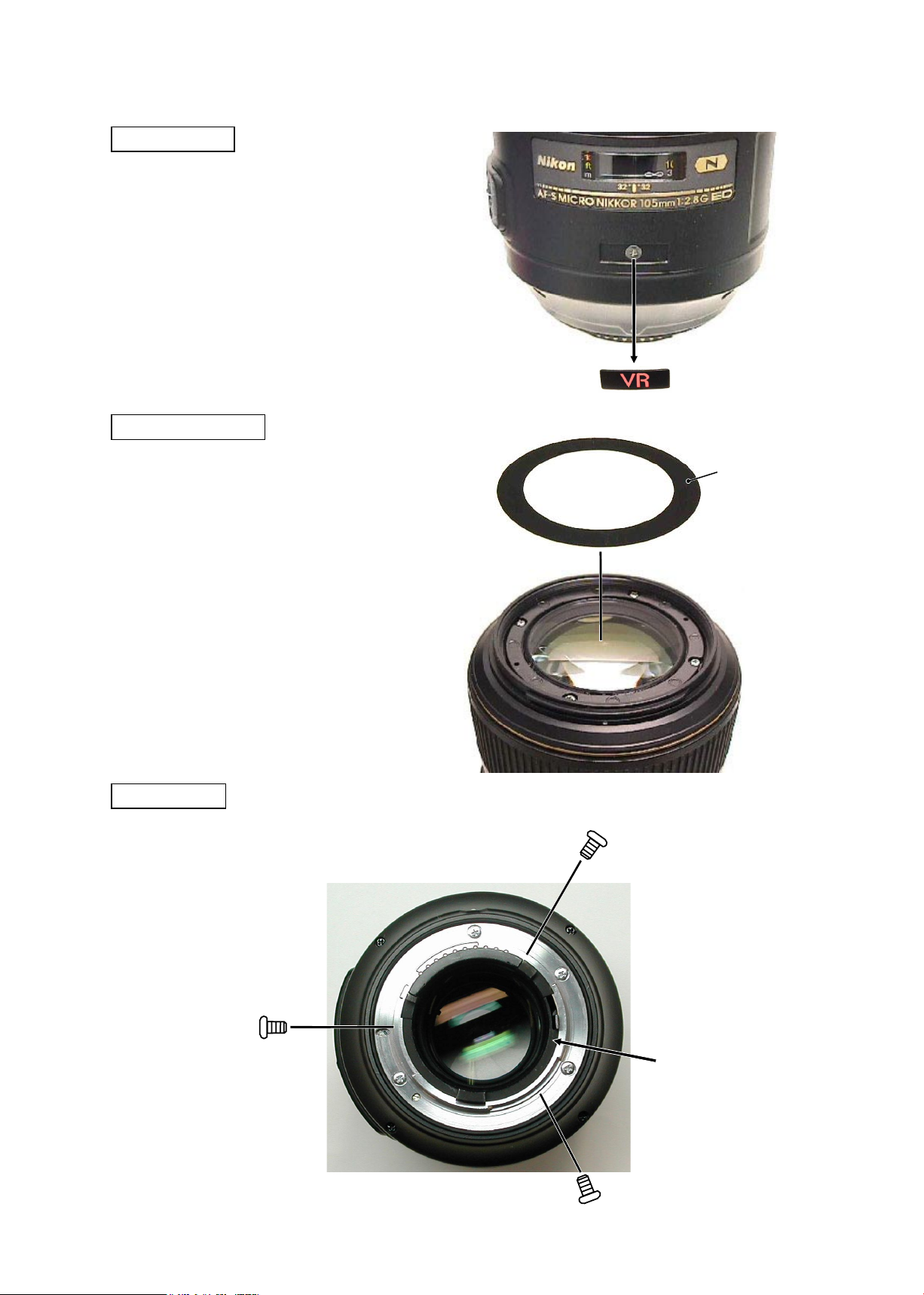
- D2・ AF-S VR MC 105/2.8G -
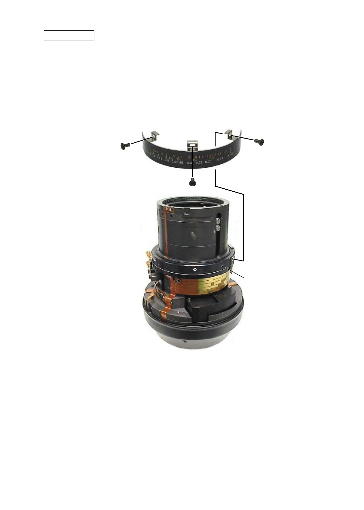
Rear cover ring
#38×3
Rear cover ring
Front cover sheet
・
Remove the front cover sheet (which is attached
with the adhesive double-coated tape).
Front cover sheet
VR name plate
・
Remove the VR name plate (which is attached
with the adhesive double-coated tape).
VR name plate
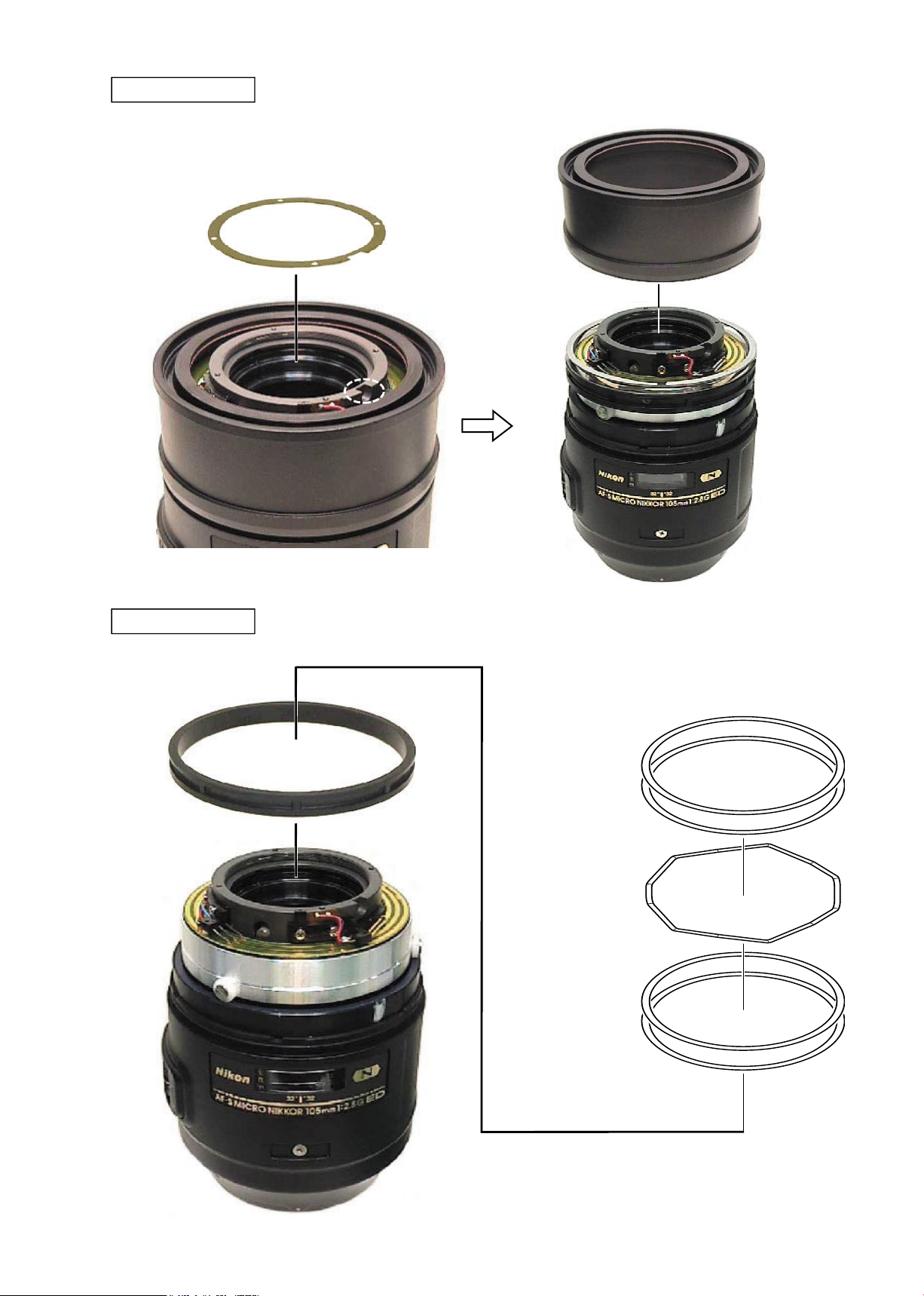
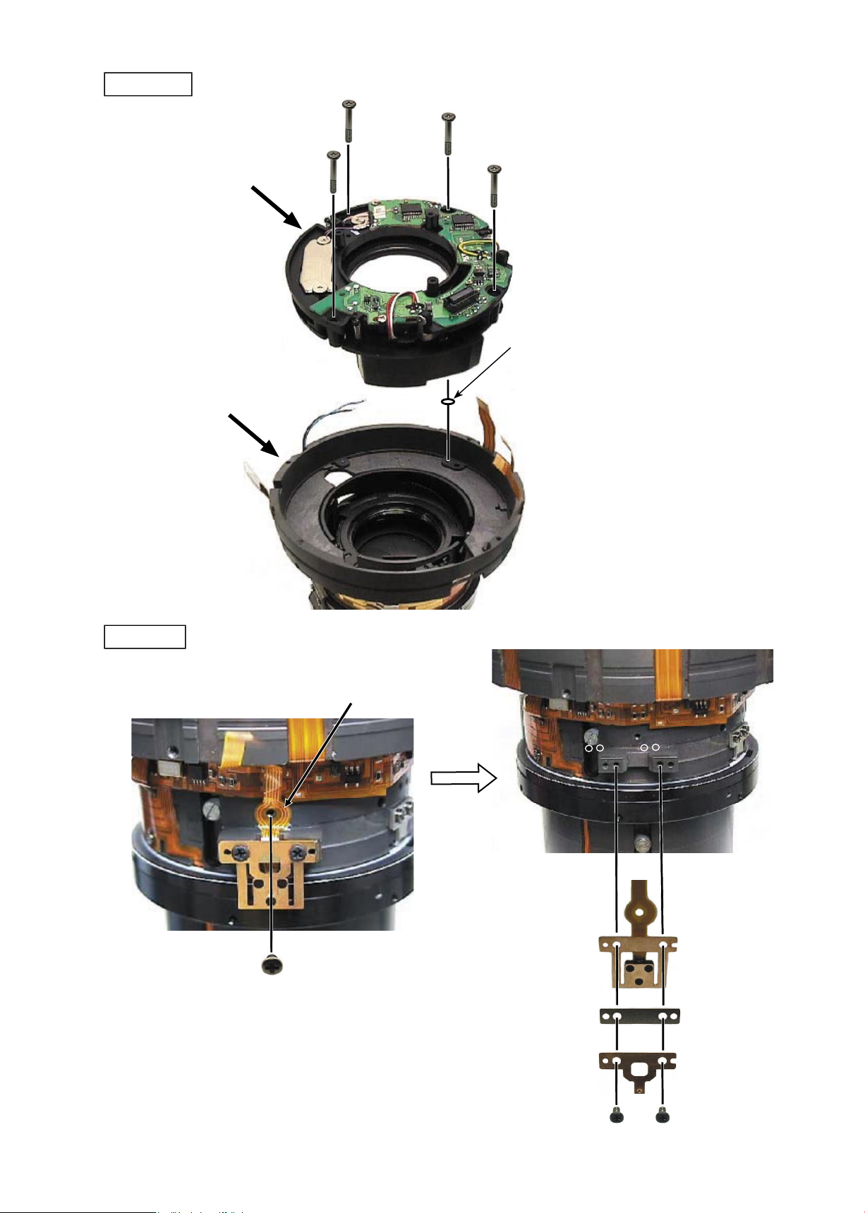
1. DISASSEMBLY
JAA63051-R.3689.A
- D3・ AF-S VR MC 105/2.8G -
5th lens group
#113×3
#151×3
5th lens group
Lens body
①
Take out the two screws (#66) to remove the
contact unit.
②
Take out the four screws (#136) to remove the
bayonet mount.
③
Take out the washer (#176).
Bayonet mount
Caution:
Removing the 5th lens group needs the lens alignment work after the assembly.
Therefore, at service facilities where the lens alignment cannot be performed, do NOT remove the 5
th
lens
group.
Contact unit
#66×2
Bayonet mount
#176
#136×4

JAA63051-R.3689.A
- D4・ AF-S VR MC 105/2.8G -
VR lens group unit
Concave
portion
Pin × 2
Hole×2
Contact
unit
③
Remove the VR lens group and washer(s) (#138 selected from A~J) with the VR lens-assembling tool
(★J11324).
④
Remove the VR- xing tool
( ★
J11321) from the lens.
VR lens
G-assembling tool
(★J11324)
VR lens group
#138A~J
★
J11321
★
New tool
★
J11321
①
Turn the VR SW to OFF.
②
Align the concave portion of the VR- xing tool (★J11321)
and the FPC of the contact unit, and t the two pins of the
tool into the two holes of the lens. Then assemble the VR-
xing tool into the lens.
JAA63051-R.3689.A
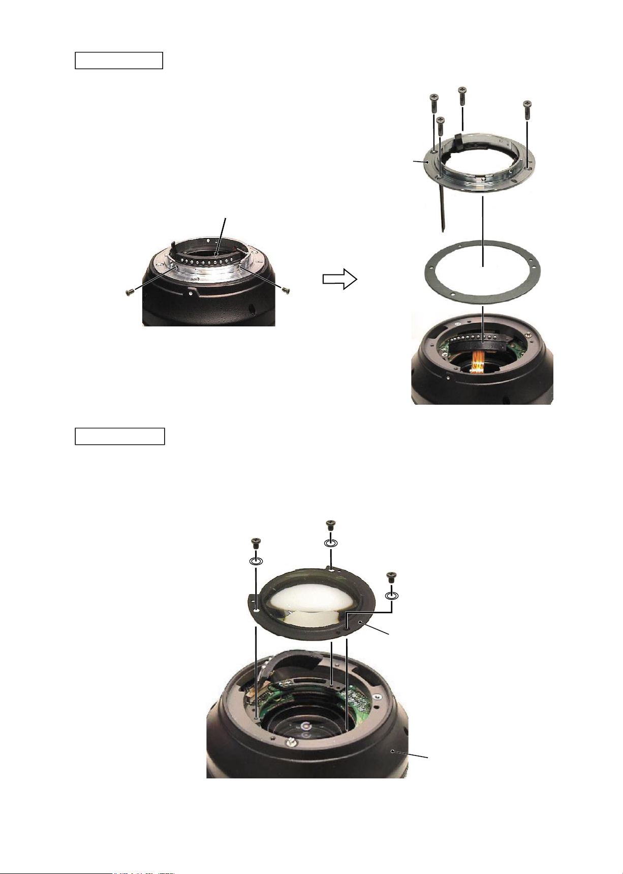
- D5・ AF-S VR MC 105/2.8G -
3rd lens group
3rd lens group
3rd lens-G
assembling tool
(★J11323)
2nd lens group, 1-2nd lens group, 1-1st lens group
Removing the 1-1st lens group needs the lens alignment work after the assembly.
Therefore, at service facilities where the lens alignment cannot be performed, do
NOT remove the 1-1
st
lens group.
①
Take out the four screws (#142) and the four washers (#151). Then
remove the 1-1st lens group and the washer(s) (#152 selected from
A-J).
②
Remove the 1-2nd lens group and the washer(s) (#137 selected from
A-J) with the 1-2nd lens-G assembling tool (★J11320).
③
Remove the 2nd lens group.
#142×4
#151×4
1-1st lens G
#152A~J
1-2nd lens G
#137A~J
2nd lens G

JAA63051-R.3689.A
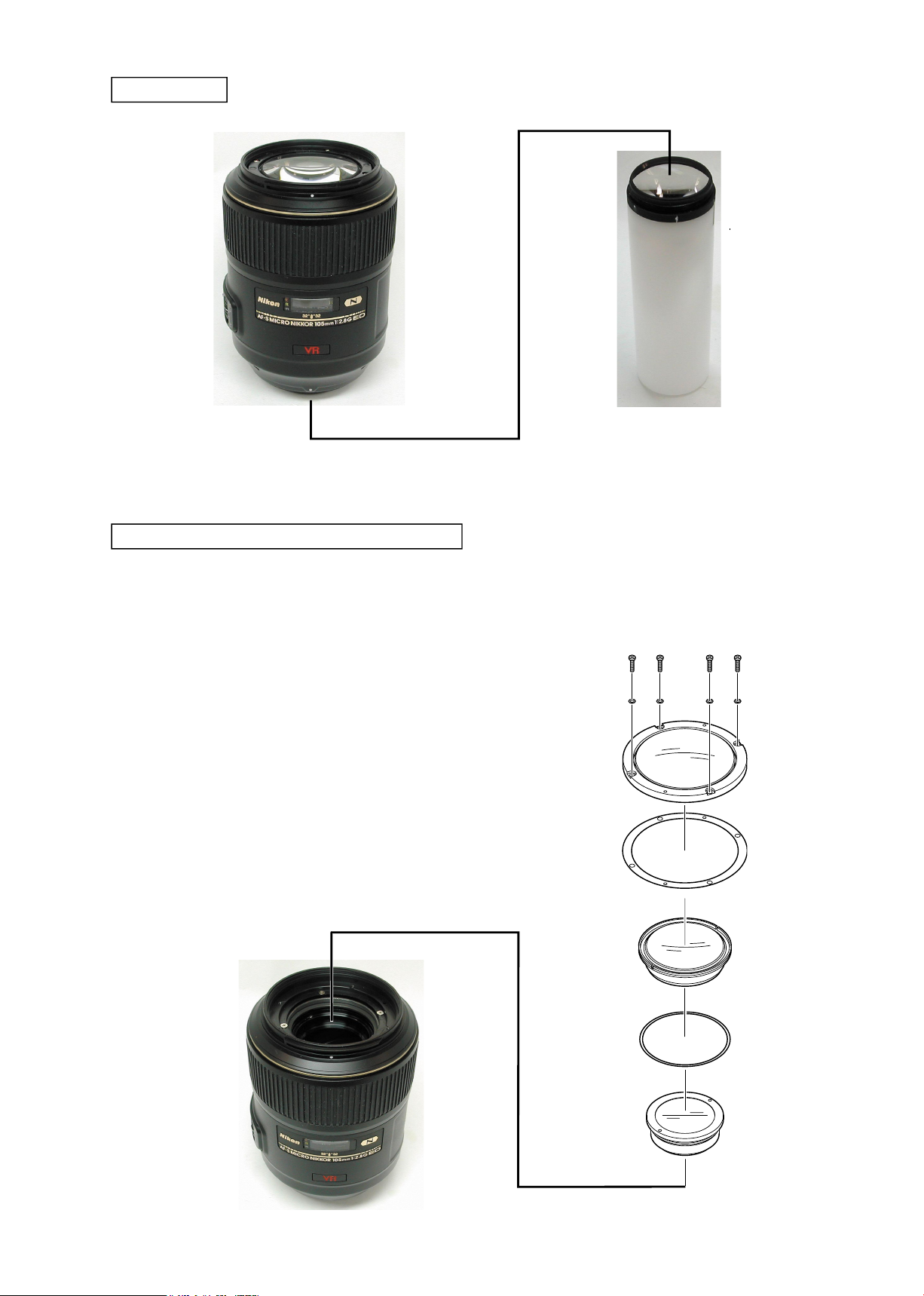
- D6・ AF-S VR MC 105/2.8G -
Rubber ring
Rubber ring
Filter ring unit
#69×4
Filter ring unit
JAA63051-R.3689.A
- D7・ AF-S VR MC 105/2.8G -
Focus ring (2) unit
Focus ring (2) unit
#175
Focus ring (1) unit
Focus ring (1) unit
#139×2
#27
#139×2
JAA63051-R.3689.A
- D8・ AF-S VR MC 105/2.8G -
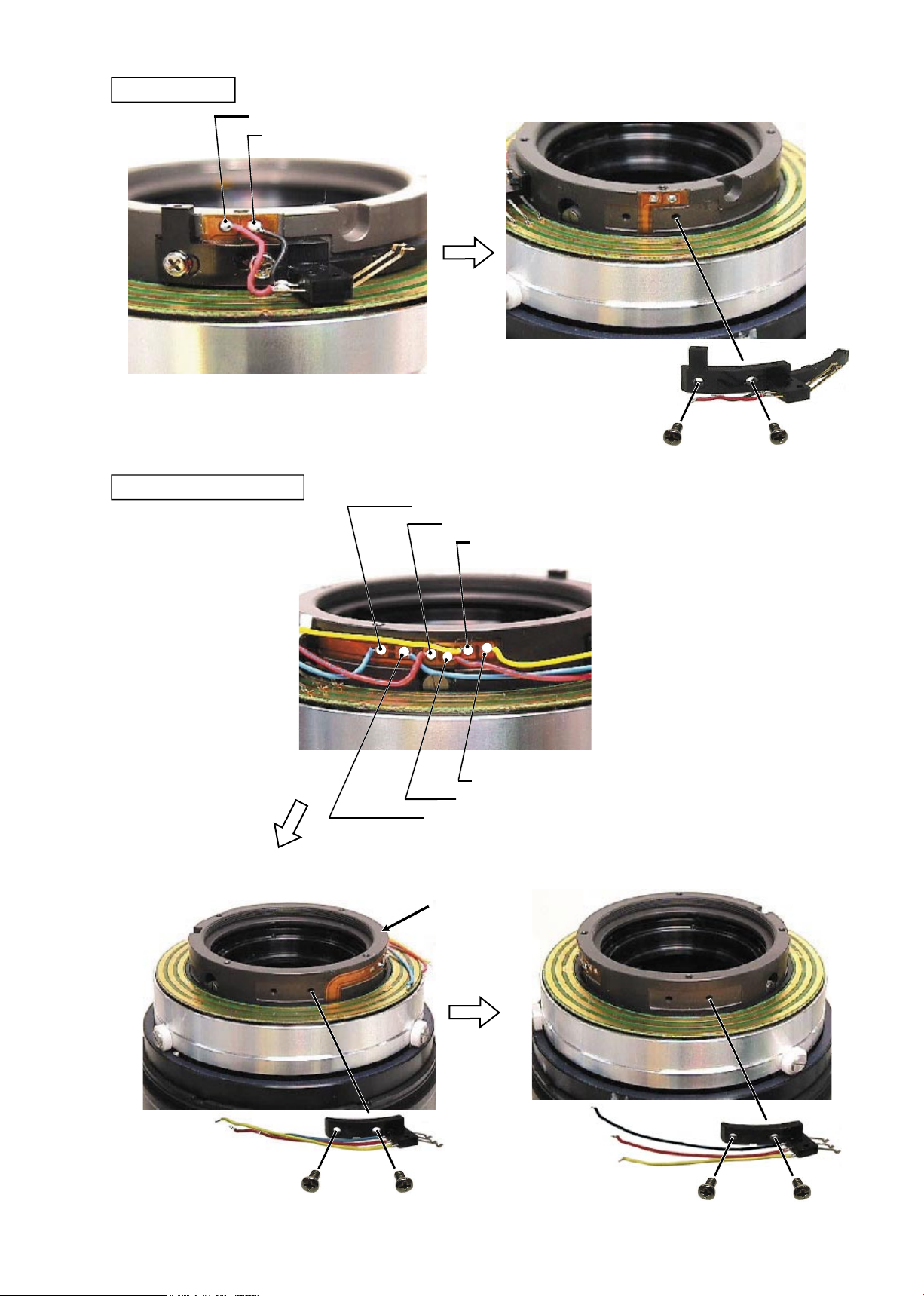
MF brush unit
Red: MF brush unit
Black: MF brush unit
#163×2
Black: Power source brush unit 1
Red: Power source brush unit 1
Yellow: Power source brush unit 1
Yellow: Power source brush unit 2
Red: Power source brush unit 2
Black: Power source brush unit 2
Power source brush unit
FS40(#56)
#163×2
#163×2
Caution: After removing the wires, suck the solder off completely. Otherwise, the SWM
unit cannot be removed.
JAA63051-R.3689.A
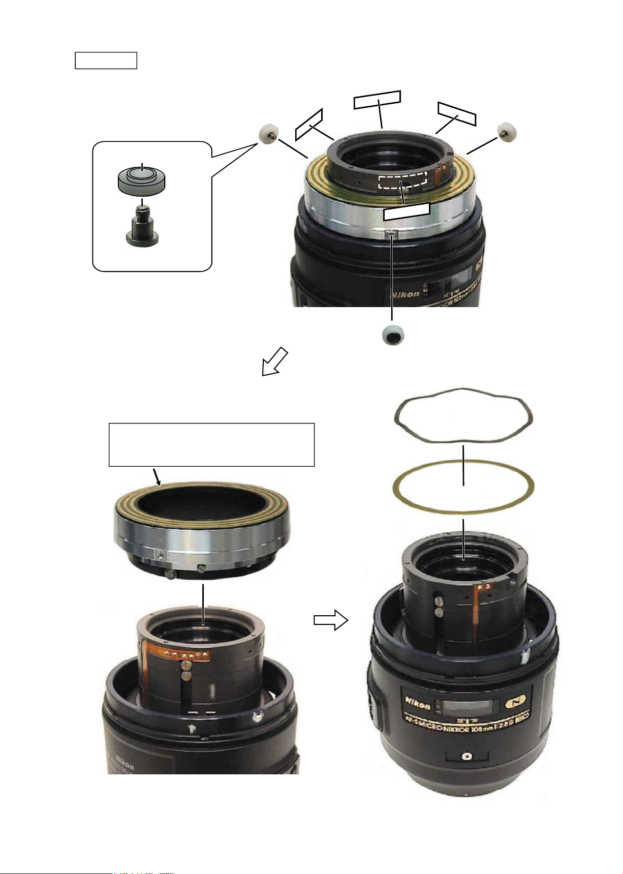
- D9・ AF-S VR MC 105/2.8G -
SWM unit
#166
#167
Caution:
When disassembling, Do NOT touch the upper
surface of the pattern.
SWM unit
#148
#147
#211×4
#148×3
#147×3
JAA63051-R.3689.A
- D10 ・ AF-S VR MC 105/2.8G -
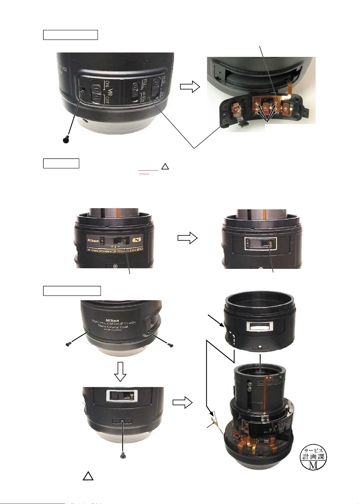
Name plate
②
Remove the focus window (#94) (which is
attached with the adhesive double-coated
tape).
①
Remove the name plate (#95) (which is attached with
the adhesive double-coated tape).
#94
#95
Change SW unit
Change-SW unit
#132
Soldering bridge×4
SW FPC
Caution: The name plate and focus ring do not have to be removed except the case when parts are replaced.
External tube unit
#118
#119×2
External
tube unit
SW FPC
window
(Misdescription)
May. 26. 2006
Changed page
× 1
JAA63051-R.3689.A
- D11 ・ AF-S VR MC 105/2.8G -
Focus index unit
#83×3
GMR unit
Focus index unit
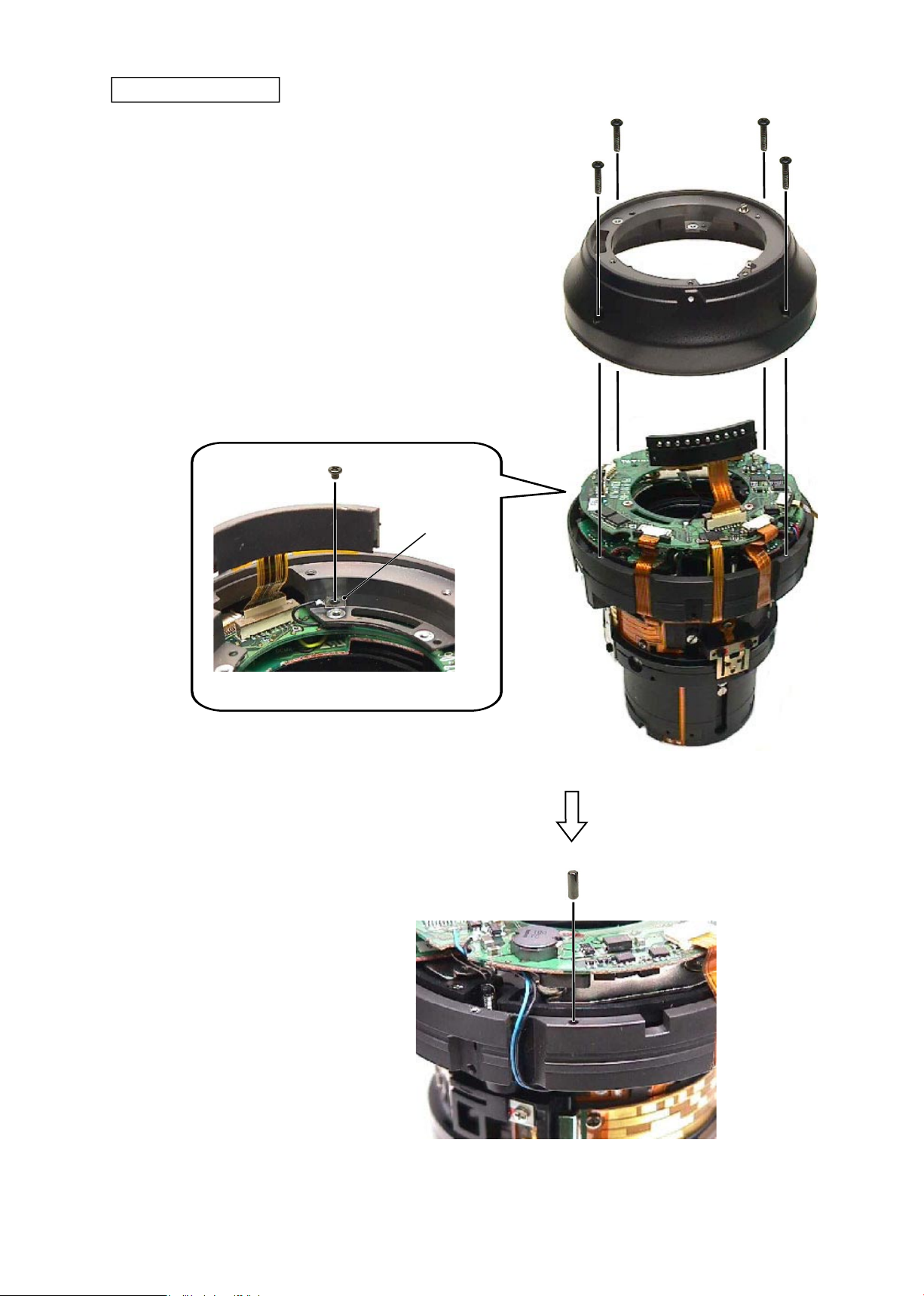
JAA63051-R.3689.A
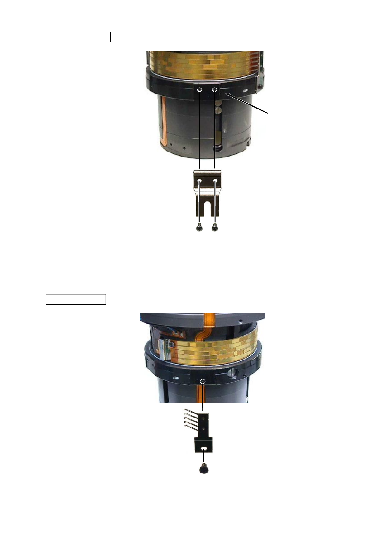
- D12 ・ AF-S VR MC 105/2.8G -
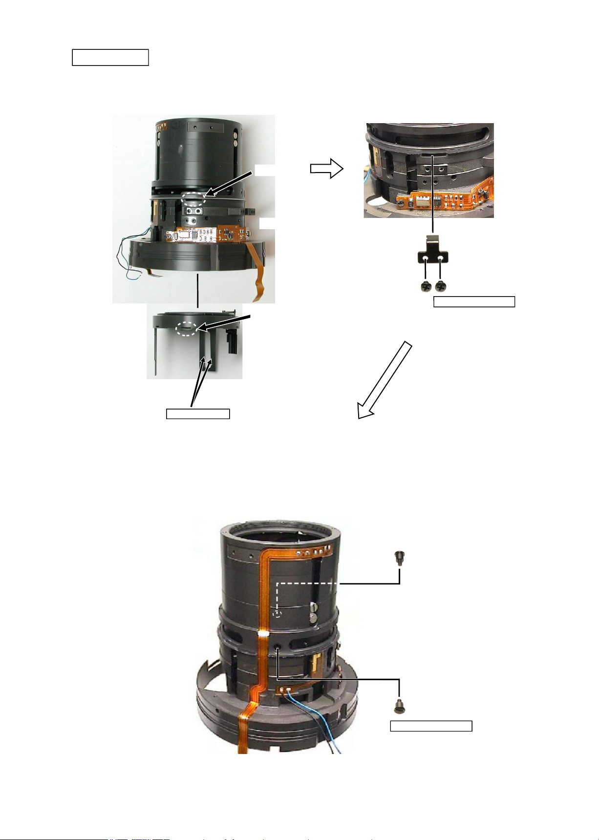
①
Take out the screw (#144), and remove the lug plate.
(ref. Fig. 1)
②
Take out the four screw (#154), and remove the rear outer
tube unit.
Fig. 1
Lug plate
#144
Rear outer tube unit
③
Remove the positioning pin (#97).
#97
Rear outer tube unit
#154×4
JAA63051-R.3689.A
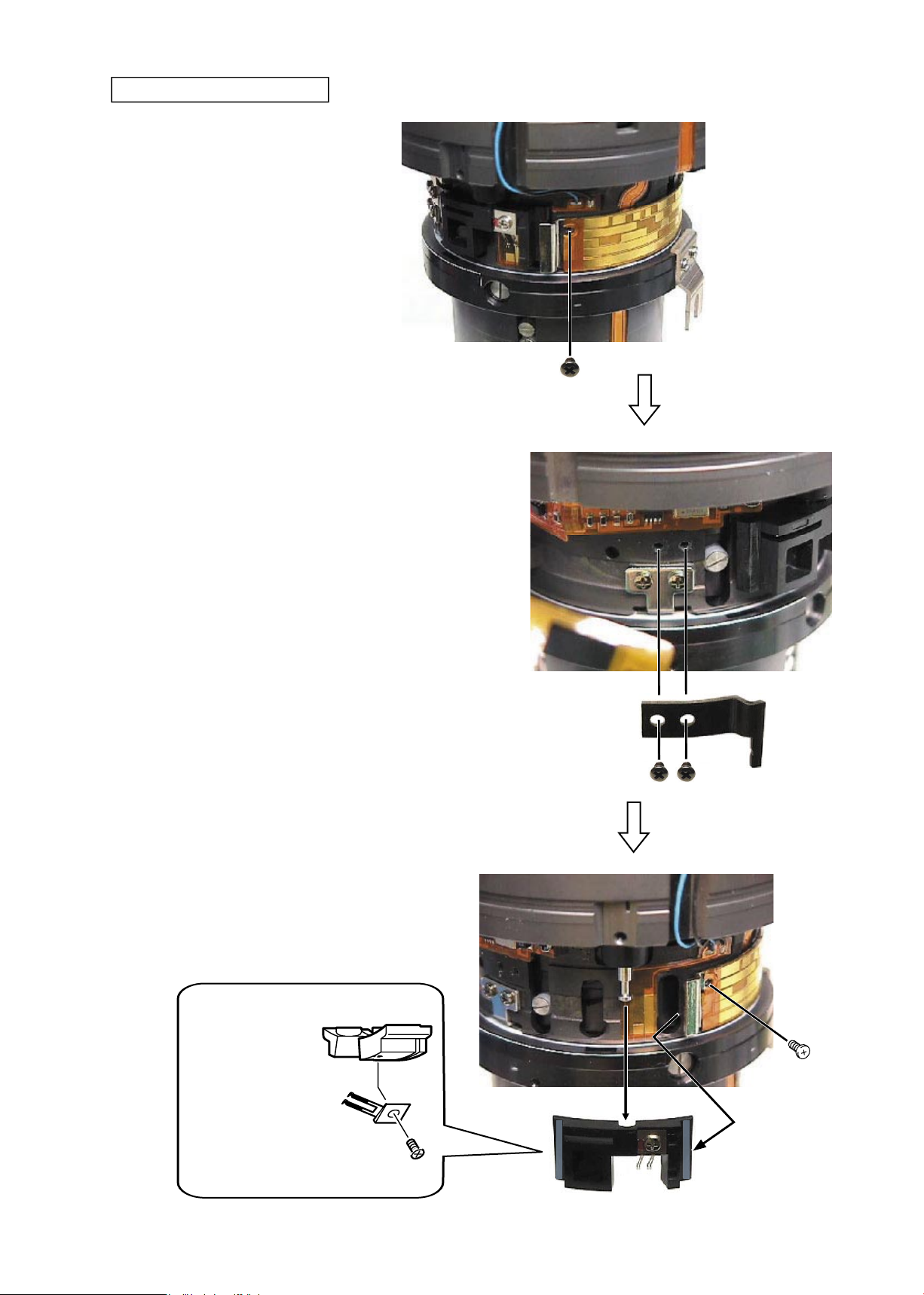
- D13 ・ AF-S VR MC 105/2.8G -
#113×2
Mechanical-coupled block
③
Remove the mechanical-coupled block. Then attach the screw
(#113) temporarily that was taken out in ①.
Mechanical-coupled
block
VR ON/OFF-change
brush
#169
②
Take out the two screws (#113), and remove the
block-retaining plate (#184).
#184
①
Take out the screw (#113).
#113
#113
JAA63051-R.3689.A
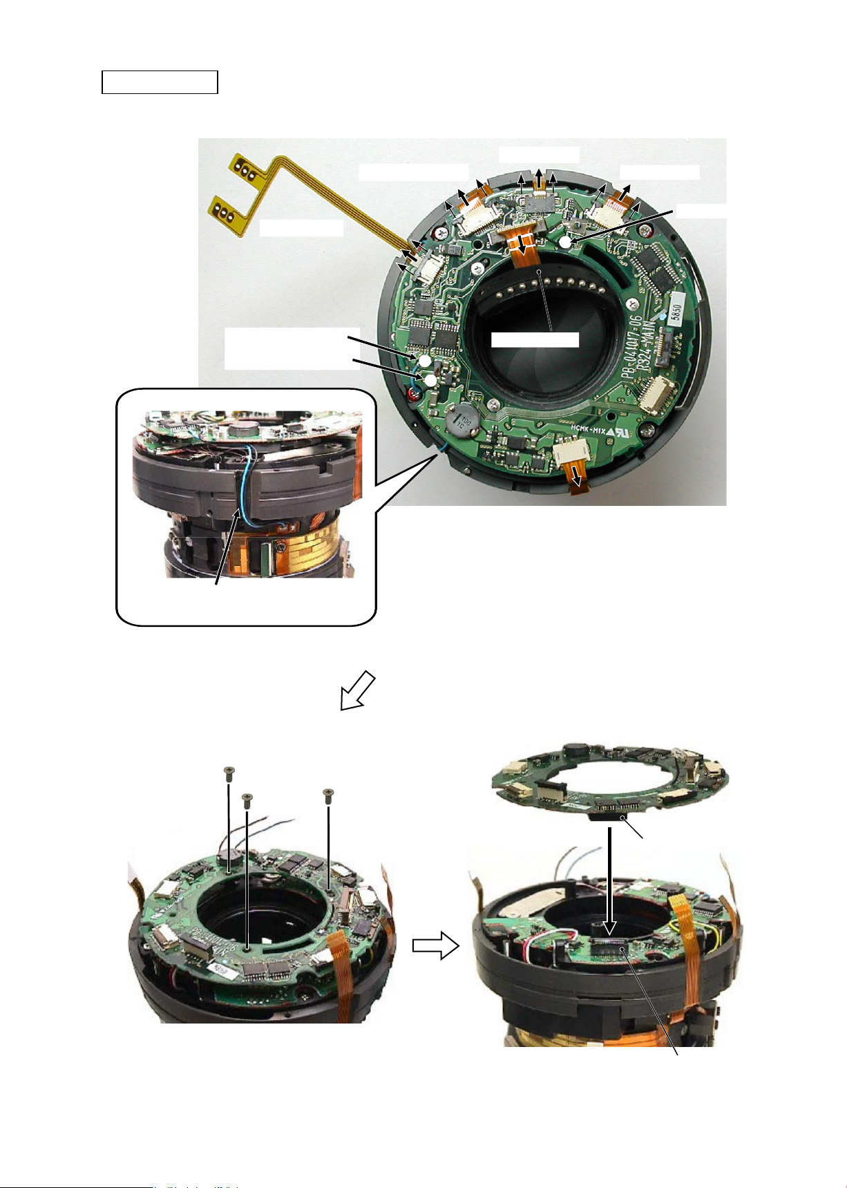
- D14 ・ AF-S VR MC 105/2.8G -
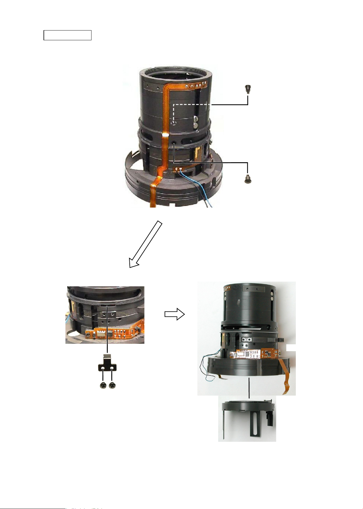
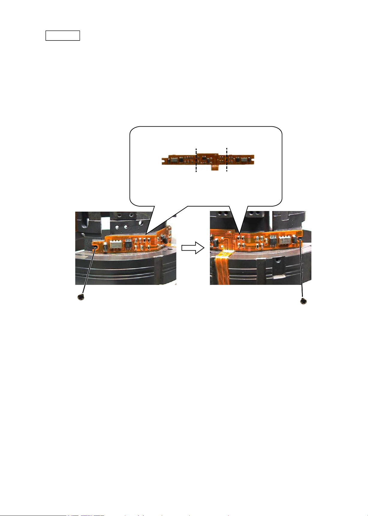
Main PCB unit
#140×3
Connector of VR unit
SW FPC
Gyro-FPC
MR FPC
Black: Lug plate
Blue: VR FPC
Black: VR FPC
Contact unit
SWM power FPC
Peel off the adhesive double-coated tape.
Focus FPC
Connector of the main PCB
JAA63051-R.3689.A
- D15 ・ AF-S VR MC 105/2.8G -
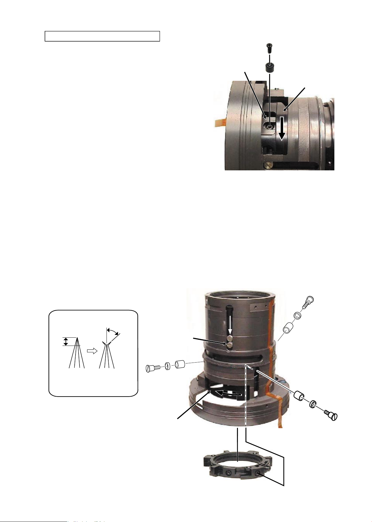
VR unit
#144
GMR FPC
#83×2
#123
#124
GMR unit
GMR unit
#160×4
VR unit
Fixed tube
Caution:
The washer(s) (191: selected from A~G)
is/are put in some VR units.
When the VR unit is NOT replaced, insert
this wahser as it is.
When the VR unit is replaced, perform
"Slant check of VR unit" on Page A12.
JAA63051-R.3689.A
- D16 ・ AF-S VR MC 105/2.8G -
Focus coupling key
Focus coupling key
#163×2
GMR tape unit
Focus brush unit
Focus brush unit
#83
JAA63051-R.3689.A
- D17 ・ AF-S VR MC 105/2.8G -
Caution 1:
Do NOT touch the tape of the GMR tape unit directly
with hands.
GMR tape unit
①
Take out the two screws (#98) through the holes
of the GMR tape unit, and remove the two rollers
(#99) and the two washers (#96).
②
Rotate the GMR tape unit in the direction of the
arrow "A" all the way to the limit, then remove it
upwards.
GMR tape unit
#98×2
GMR tape
#99×2
#96×2
Fixed tube
Focus restriction section
A
Focus restriction section
#120
Fixed tube
#79
#134
#133
Fixed tube
JAA63051-R.3689.A
- D18 ・ AF-S VR MC 105/2.8G -
Focus FPC unit
②
Peel off the focus FPC from the xed tube.
①
Peel off the focus FPC from the xed tube.
Fixed tube
Focus FPC
Focus FPC
④
Take out the left-side screw (#113) of the focus
FPC unit, and remove the focus FPC unit.
③
Take out the right-side screw (#113) of the
focus FPC unit.
#113
Focus FPC unit
#113
JAA63051-R.3689.A
- D19 ・ AF-S VR MC 105/2.8G -
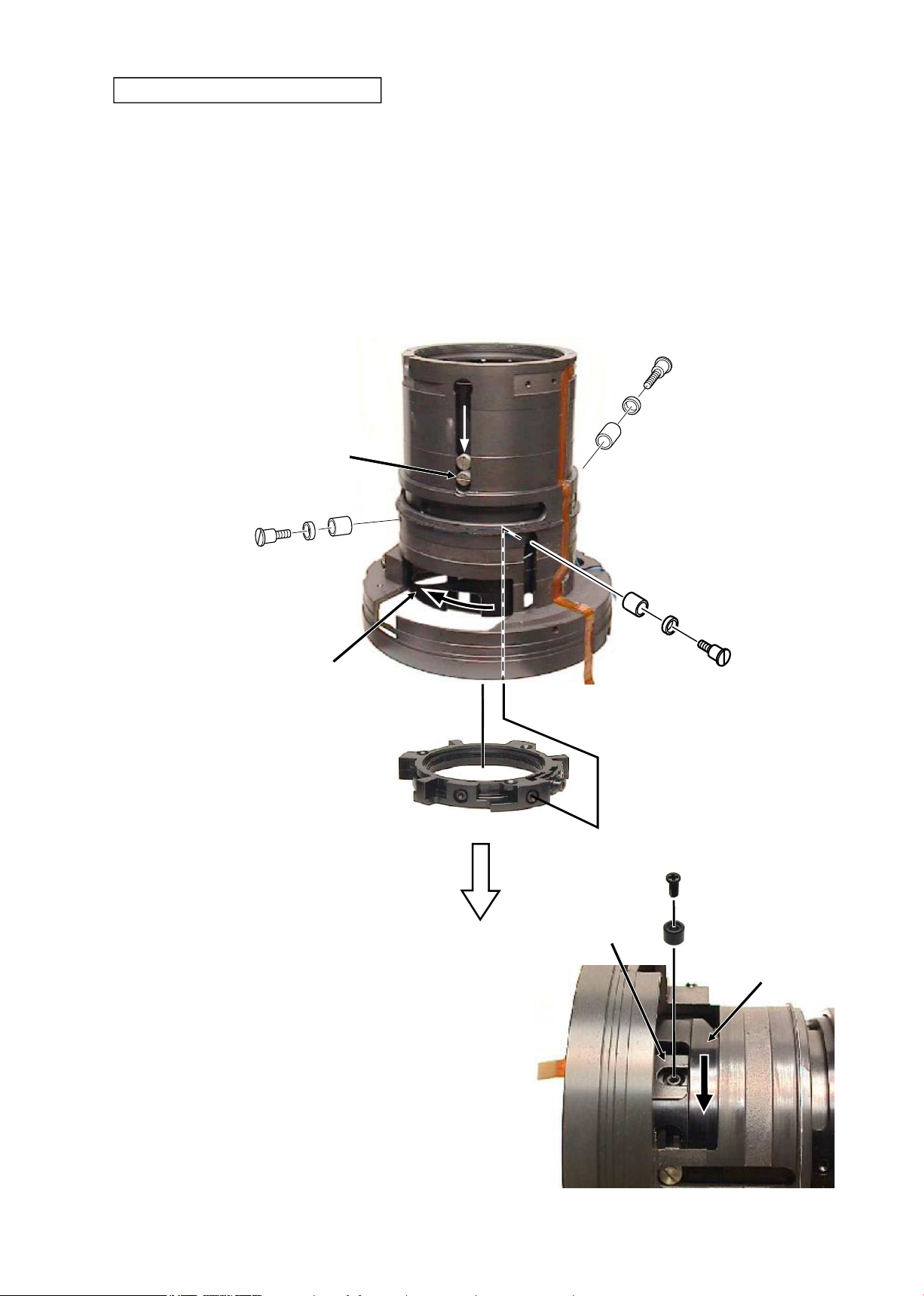
③
Rotate the cam ring in the direction of the arrow until the roller (B28) is positioned
lowered.
④
Take out the three screws (#78).
⑤
Remove the three pairs of the roller (#77 selected from A-F) and the roller (#76
selected from A-F) with the new tool, X-type slim tweezers (★J11326), or an
equivalent tool.
⑥
Remove the 3rd lens-G movement frame unit.
3rd lens-group movement-frame unit
Roller (B28)
#78×3
#77A~F×3
#76A~F×3
Cam ring
3rd lens-G movement frame unit
①
Rotate the cam ring in the direction of the arrow
until the hole of the 3rd lens-G movement frame
unit can be seen from the groove of the aperture
unit.
②
Take out the screw (#158), and remove the roller
(#157A~D).
Aperture unit
#158
#157A~D
Cam ring
Approx.1.5mm
Approx.70°~80°
★
New tool
● Fold the tip of the X-type slim tweezers
(★J11326) as below, and use it.
Folding of X-type slim
tweezers
JAA63051-R.3689.A
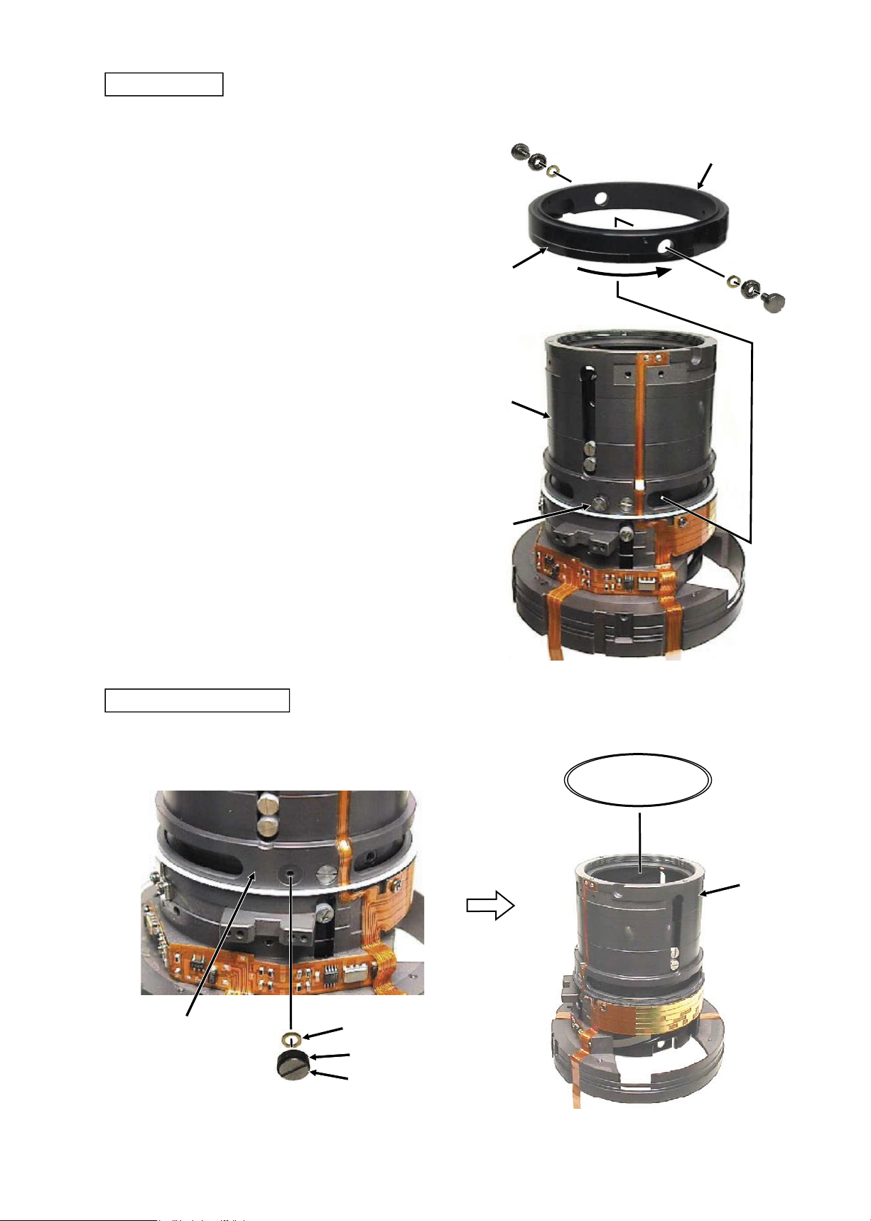
- D20 ・ AF-S VR MC 105/2.8G -
Aperture unit
#114
Aperture unit
#113×2
#92×2
Lens body
JAA63051-R.3689.A
- D21 ・ AF-S VR MC 105/2.8G -
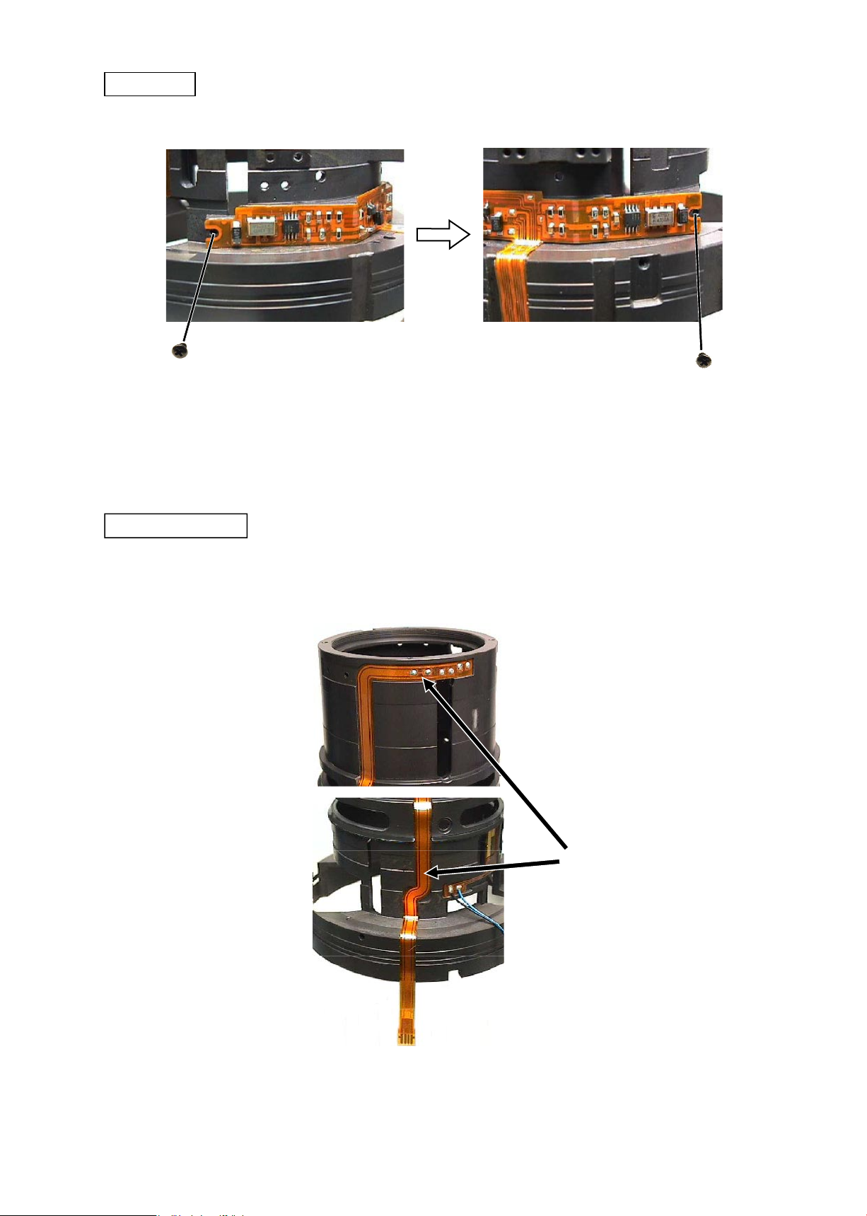
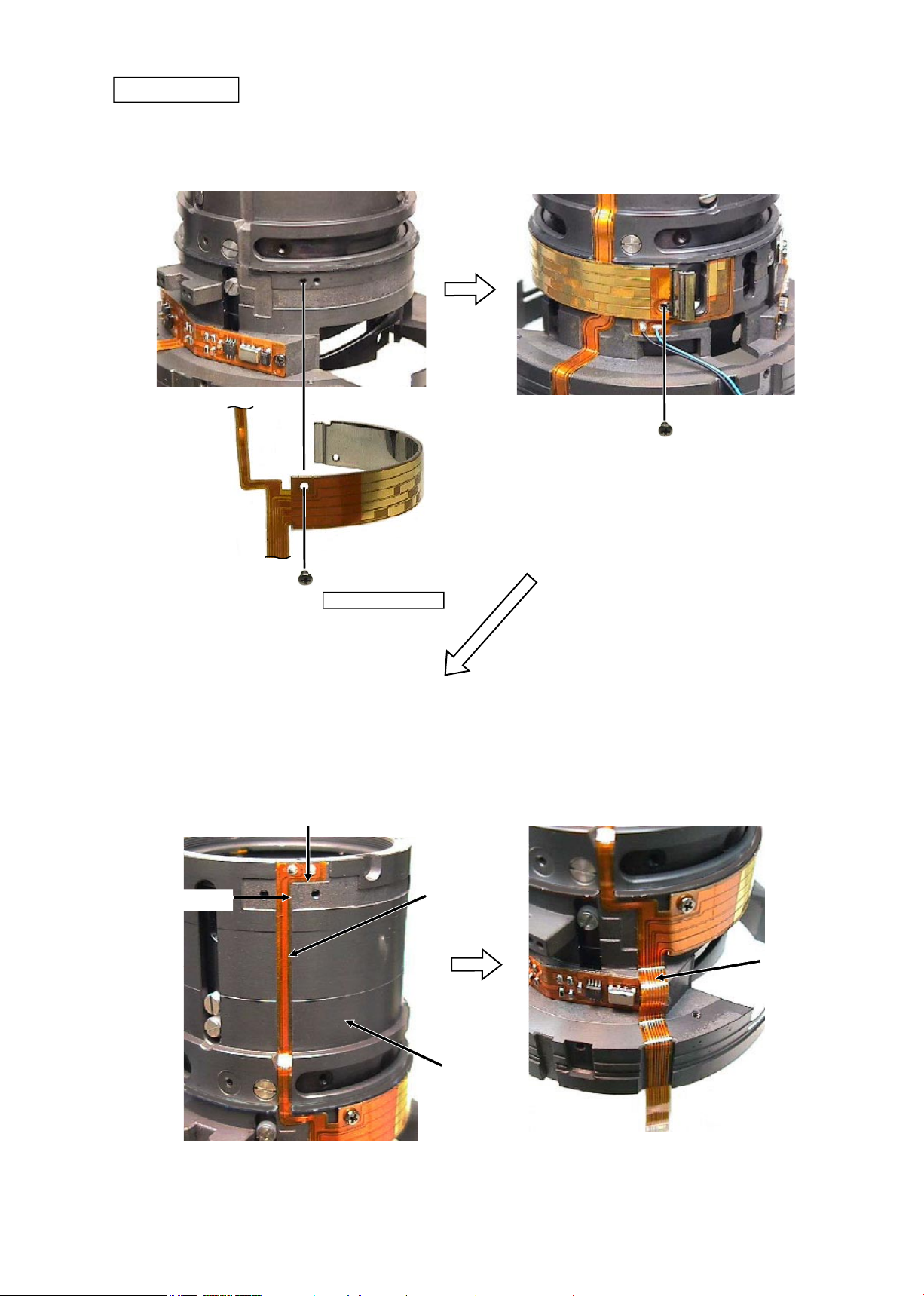
Gyro-FPC
#113
#113
・
Peel off the SWM power FPC from the xed tube unit.
(
SWM power FPC is attached with the adhesive double-coated tape.)
SWM power FPC
SWM power FPC
JAA63051-R.3689.A
- D22 ・ AF-S VR MC 105/2.8G -
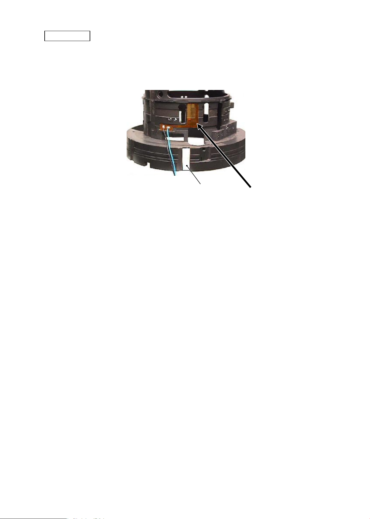
VR FPC
・
Peel off the VR FPC from the xed-tube unit.
(
VR FPC is attached with the adhesive double-coated tape.
)
VR FPC
Adhesive double-coated tape (#183)
JAA63051-R.3689.A
- A1・ AF-S VR MC 105/2.8G -
2 ASSEMBLY / ADJUSTMENT
VR FPC
・
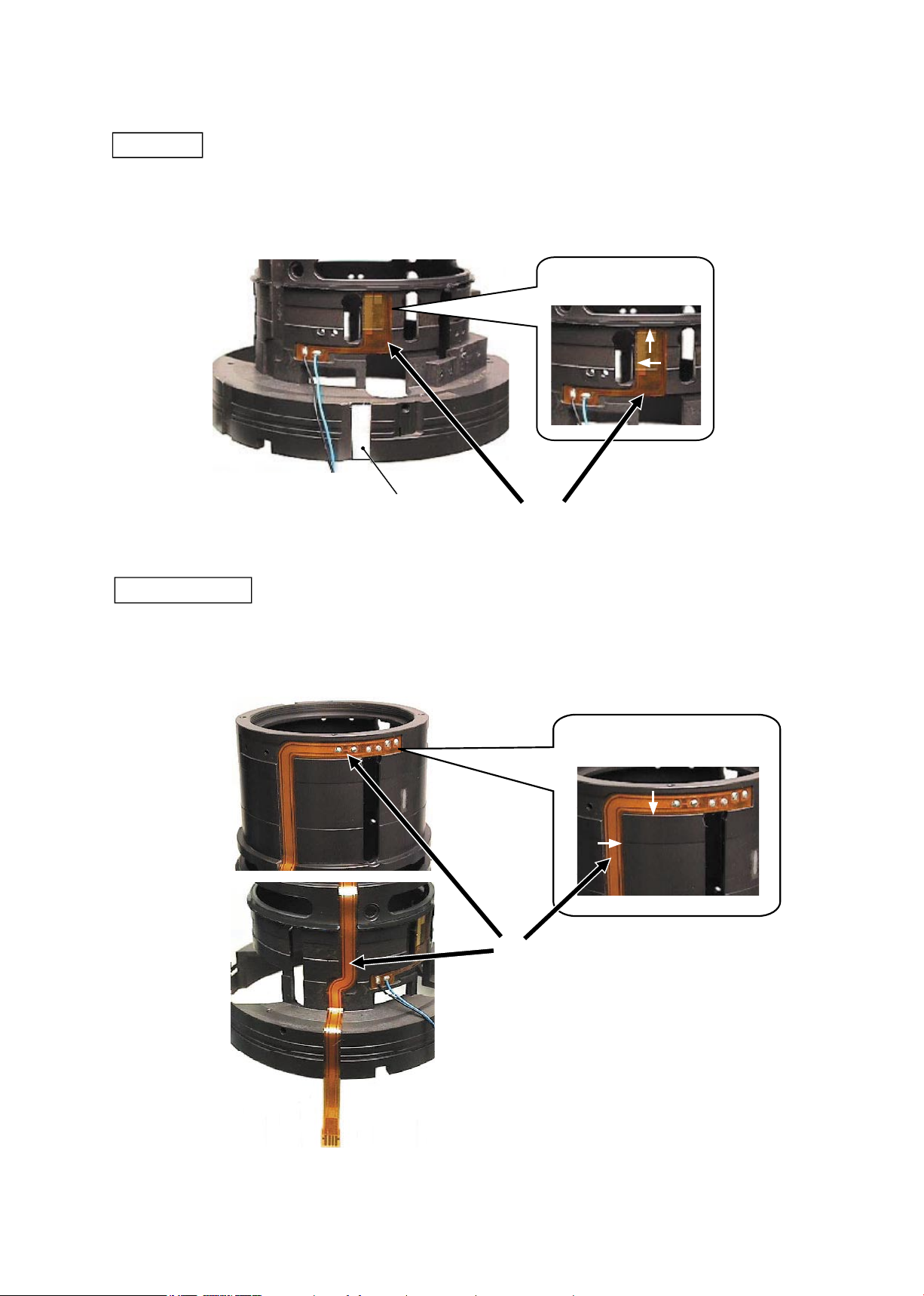
Attach the VR FPC on the xed lens-barrel unit.
(VR FPC already has the adhesive double-coated tape adhered.)
・
Attach the adhesive double-coated tape (#183) at the below position.
Reference position for
attachment
VR FPC
Adhesive double-coated tape (#183)
・
Attach the SWM-power FPC on the xed lens-barerl unit.
(SWM-power FPC already has the adhesive double-coated tape adhered.)
Reference position for attachment
SWM power FPC
SWM-power FPC
JAA63051-R.3689.A
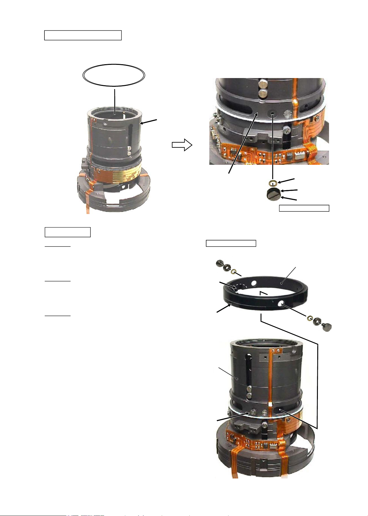
- A2・ AF-S VR MC 105/2.8G -
#113
#113
Gyro-FPC
①
Attach the gyro-FPC on the xed lens-barrel unit.
(Gyro-FPC already has the adhesive double-coated tape adhered.)
②
Fix it with the two screws (#113).
Mountain-fold Mountain-fold
JAA63051-R.3689.A
- A3・ AF-S VR MC 105/2.8G -
#114
#113×2
#92×2
Aperture unit
①
Align the grooves of the aperture unit and the lens
body, and assemble them.
②
Set the key (#114) by tting its upper part in the
groove of the aperture unit. Then x it with the two
screws (#113).
Lens body
Groove
Aperture unit
Grease: G92KA
Adhesive:Lockend B
Apply to groove.
Groove
③
Fix the aperture unit with the two screws (#92).
Adhesive:Lockend B
JAA63051-R.3689.A
- A4・ AF-S VR MC 105/2.8G -
#78×3
#77A~F×3
#76A~F×3
#158
#157A~D
①
Rotate the cam ring in the direction of the arrow until the roller (B28) is positioned lowered.
②
Put the 3rd lens-G movement-frame unit inside the cam ring as shown below.
③
Fix three pairs [of the roller (#76 selected from A
-
F) and the roller (#77 selected from A
-
F)] with the
three screws (#78).
Caution: Choose rollers
(
#76 and #77) which are slightly tight for each groove.
3rd lens-group movement-frame unit
Roller B28
Cam ring
3rd lens-G movement frame
④
Rotate the cam ring in the direction of the arrow until
the screw hole of the 3rd lens-G movement frame
can be seen from the groove of the aperture unit.
⑤
Fix the roller (#157 selected from A
~
D) with the
screw (#158).
Aperture unit
Cam ring
JAA63051-R.3689.A
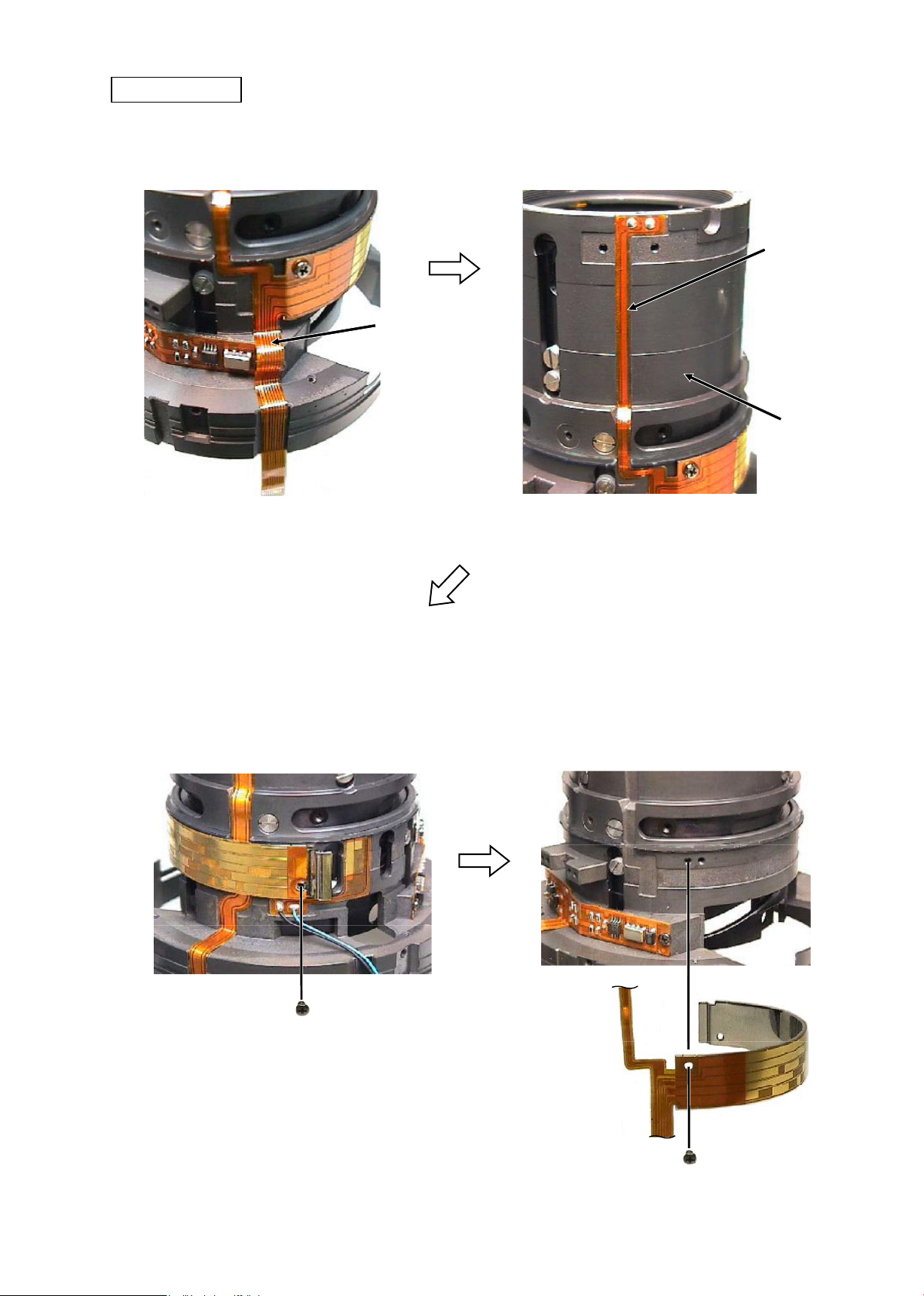
- A5・ AF-S VR MC 105/2.8G -
#113
#113
Focus FPC
Focus FPC unit
①
Fix the left side of the focus FPC unit with the
screw (#113).
②
Tighten the right side of the focus FPC unit with
the screw (#113) temporarily.
Tighten temporarily
Adhesive:Lockend B
Focus FPC unit
③
Attach the focus FPC on the xed tube,
according to the reference position.
④
Attach the focus FPC by conforming to the shape
of the xed tube.
Reference position
Reference position
Fixed tube
Focus FPC
JAA63051-R.3689.A
- A6・ AF-S VR MC 105/2.8G -
#120
#79
#134
#133
#98×2
#99×2
#96×2
Focus restriction section
①
Assemble the teon sheet (#120) in the xed tube.
②
Fix the restriction rubber (#134) and the washer
(#79) on the xed tube with the screw (#133).
Fixed tube
Adhesive:Lockend B
Fixed tube
Caution 1
:
Do NOT touch the tape of the GMR tape unit
directly with hands.
Caution 2
:
The ball-bearing visible side of the roller (#99) must
come to the washer (#96)-side.
Caution 3
:
The chamfered side of the washer (#96) must come
to the roller (#99)-side.
GMR tape unit
①
Align the concave portion of the GMR tape unit
with the focus restriction portion, then assemble
the GMR tape unit into the xed tube.
GMR tape unit
Concave
portion
GMR tape
Fixed
tube
Focus restriction section
Adhesive:Lockend B
②
Fix each two pairs [roller (#99) and
washer (#96)] with the screws (#98)
by passing the body of the screws
(#98) through the holes of the GMR
tape unit.
 Loading...