

Page 1

NO/TG-7
NIGHT OPTICS USA
THERMAL
GOGGLES
OPERATOR’S MANUAL
The NO/TG-7 Goggle/Binocular is a rugged, lightweight, and powerful InfraRed
device that can be hand held or mounted on a headgear. By using the 2x internal
digital zoom and adding an optional a-focal germanium optical magnication
lens, the NO/TG-7 provides up to 9x long-range thermal surveillance and
acquisition.
Page 2

TABLE OF CONTENTS
Revision Notices 2
Table of Contents 3
Warnings and Cautions
Chapter 1: Introduction
1-1. Description 5
1-2. What is Infrared? 5
1-3. Theory of operation 5
Chapter 2: System Components
2-1.Standard Conguration 6-7
2-2. Optional Accessories 7
Chapter 3: System Controls
3-1. Power Source 8
3-2. Activation (IR/pull Position) 8
3-3. Reset/OFF-ON-IR/pull Position 8
3-4. Focus Adjustment 8
3-5. White-Hot/Black-Hot button switch 9
3-6. 2X Digital Zoom 9
3-7. Head Mount Assembly with Brow Pads 9
Chapter 4: Receipt, deactivation, cleaning and storing the system
4-1. Service upon receipt of material
4-2. Deactivation 10
4-3. Battery Removal 10
4-4. Cleaning Outer Unit 10
4-5. Cleaning Optics 10
4-6. Purging 10
4-7. Storage 11
4-8. Inspection 11
Chapter 5: System Operations
5-1. Display Graphics 12
5-2. Operation with External Power 12
5-3. Operation using Video Output Cable 13
Chapter 6: Specications
6-1. Detector 14
6-2. Performance 14
6-3. Physical Features 14
6-4. Additional Features 14
Chapter 7: Operator Preventive Maintenance Checks and Troubleshooting
7-1. Preventive Maintenance Checks 15
7-2. Discrepancies, Probable Cause and Suggested Actions 16
4
Appendix A: Electronic Block Diagram 17
Page 3

CHAPTER 6. SYSTEM SPECIFICATIONS
6-1. Detector
• FPA Format: 160 x 120
• Type and Material: Amorphous Silicon Microbolometer
• Cooling: Uncooled
• Spectral Response Sensitivity: 7 – 14 μm
• NETD (Thermal Sensitivity): < 50mK
• Refresh Rate: Real-time 30Hz
6-2. Performance
• Detect Stationary Man: 475+ meters
• Optics: 25mm, 1.5X, f1.0
• Magnication (standard): 1.5X
• Magnication (with 2X digital zoom): 3.0X
• Continuous Operation (AA Batteries): 4 hours
6-3. Physical Features
• Diopter Adjustment: -6 to +2
• Eye Relief: 17mm
• Weight: 17.1 oz (485 g)
• Dimensions: 6in x 6in x 4in
• Power Requirement: (3) CR123 batteries
• Lens: High Grade Germanium
• Output Video output NTSC Composite
• Eyepiece Adjustment: Focus & Interpupillary distance
6-4. Additional Features
• Polarity Control: Black Hot/White Hot
• Display: 640 X 480 pixels
• Temperature Reading: Yes
• Colorization: Gray Scale Color available on
request
• Video Output: NTSC (STD) PAL (on request)
• Video display Battery level indicator (lower right)
Page 4

WARNINGS AND CAUTIONS
CAUTION (Section I):
Do not remove the housing. There are no user serviceable parts inside. Refer all servicing to
Night Optics USA, Inc.
WARNING (para. 3-1):
Ensure that the switch is in the OFF position before installing or removing batteries, and
connecting or disconnecting to any external power source.
WARNING (para 3-1):
Ensure that the input power does not exceed 24VDC: use a power converter if needed.
WARNING (para 4-1):
Breaking the seal on the Back Plate (see b above) invalidates the warranty.
DO NOT BREAK THE SEAL.
WARNING (para 4-6):
Purging is not user level maintenance. Contact Night Optics or your Support Maintenance
activity.
CAUTION (para 4-7):
Do not store the NO/TG-7 with the batteries installed.
WARNING (para 5-2):
Do not connect the NO/TG-7 to any external power source while the unit is turned on.
EXPORT RESTRICTIONS:
Export of Thermal devices is subject to United States Export rules and regulations. Valid
export licenses may be issued by the U.S. Department of Commerce or the U.S. Department of
State, Directorate of Trade Controls, in accordance with the International Trac in Arms
Regulations (ITAR), Title 22, Code of Federal Regulations 120-130. Consult Night Optics USA,
Inc. for additional information regarding export requirements.
Page 5

SECTION I: OPERATOR INSTRUCTIONS
CAUTION
DO NOT REMOVE THE HOUSING.
THERE ARE NO USER SERVICEABLE PARTS INSIDE.
REFER ALL SERVICING TO NIGHT OPTICS USA, INC.
Chapter 1. Introduction
1-1. Description:
The NO/TG-7 Thermal Goggle/Binocular is a rugged, lightweight and powerful Infrared optic that can be
hand-held, helmet mounted, or mounted on a head harness. By using the 2X internal digital zoom and
adding an optional afocal germanium optical lens, the NO/TG-7 provides potent 6X long-range thermal
surveillance and acquisition.
The sensitive uncooled thermal detector and high resolution display provides crisp “white hot” or “black
hot” images regardless of ambient conditions. A colorized capability is available at user request. While
night vision technology relies on amplication of ambient light or assisting illumination, thermal
devices are completely passive, sensing extremely minute temperature dierentials. The NO/TG-7
Thermal Goggle therefore acquires targets in daylight and complete darkness while “seeing through”
obscurants such as smoke and haze which often hinder image intensication devices.
Designed for law enforcement, military and commercial use, the NO/TG-7 is ideal for reconnaissance and
surveillance, perimeter security, wildlife observation and control, locating oil spills, and geo-thermal
event monitoring in addition to a wide variety of other applications.
1-2. What is Infrared?
Infrared energy, often referred to as “infrared” or “IR”, is electromagnetic radiation that travels in a
straight line through space, the same as visible light. Although infrared energy shares some of the
properties of visible light, its dierent wavelength has several unique characteristics. For instance,
materials that are opaque to visible light may be transparent to infrared, and vice versa. An example of
this dierence is the ability of light intensication devices to see through glass and plastic while thermal
detection devices cannot. Unlike visible light, given o by ordinary objects only at very high
temperatures (e.g. light bulbs), long-wavelength infrared (7-14 mm) is emitted by all objects at ordinary
temperatures. This means that infrared energy surrounds us all the time, even in the dark. Dierent
objects emit varying amounts of infrared energy depending on the temperature of the object. The
NO/TG-7 is designed to sense diering contrasts of long-wavelength infrared energy and display the
scene in real time for the user.
1-3. Theory of Operation:
The NO/TG-7 combines a highly sensitive, 30μm 160x120 uncooled, Amorphous Silicon Microbolometer
detector yielding a real-time 30Hz frame rate with a 640 X 480 LED display integrated and sealed in a
modied PVS-7 housing. With thermal sensitivity of less than 50mK, the sensor has a 7-14μm spectral
response. The 1°x8° eld of view provided by the 25mm lens facilitates detection of human activity to
475 meters. Additional integrated features include focus adjustment, white-hot/black-hot polarity
options, contrast and brightness adjustment, 2x digital zoom, hand-held battery operation, NTSC
video-out capability and external power function. The sealed system has a nitrogen purge screw in the
rear cover assembly.
Page 6

CHAPTER 4. RECEIPT, DEACTIVATION, CLEANING AND STORING THE SYSTEM CONT
4-7. Storage:
Replace lens caps, as required. Wrap the lanyard around the NO/TG-7 and store in the carrying
case. For extended storage, remove all batteries.
Do not store the NO/TG-7 with the batteries installed.
4-8. Inspection:
Conduct an inventory of the case and its contents and report missing or damaged items for
replacement. Once the components are clean, dry and inventoried, close the case and place it
in secure storage. The Mil Spec storage case is highly recommended.
CAUTION
Page 7

Chapter 2. System Components
2-1. Standard conguration
The NO/TG-7 ships with the following standard components:
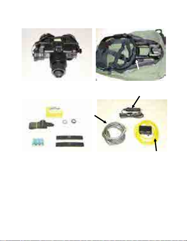
NO/TG-7 Thermal Goggle System (g. 1) (1)
Soft Carrying Case (g. 2a) (1)
3v CR123 Batteries (g.3a) (3)
Demist Shield (g. 3b) (2)
Shoulder Strap (g. 3c) (1)
Lens Tissue (g.3e) (1)
Eye-Cups (g. 1b) (2)
Lens Cap (g. 1a) (1)
Lanyard (g. 1c) (1)
Operator’s Manual (not pictured) (1)
Video Output Cable (VOC) (Silver) (g. 4a) (1)
External Power Cable (EPC) (Cigarette Lighter Adapter) (g.4b) (1)
Integrated Power Video Connection (IPVC) (Yellow) (g. 4c) (1)
Page 8
CHAPTER 2. SYSTEM COMPONENTS contd
(c)
(b)
(c)
(a) (d) (a)
Optional Accessories:
Headmount Assembly (g. 2b) with Brow Pads
3X Magnier Lens (not shown)
Mil Spec Carrying Case (not shown)
(a)
fig. 1 fig. 2
(e)
(b)
fig. 3 fig. 4
(b)
VOC
(c)
(a)
EPC
(b)
(c)
IPVC w/Cable
Page 9
CHAPTER 3. SYSTEM CONTROLS
The NO/TG-7 is very easy to operate: See paragraphs 3-1 to 3-6 below for detailed instructions. Contact
Night Optics USA Inc. at (714)-899-4475 for additional information or assistance.
3-1. Power source:
The electronic circuit is powered by three (3) replaceable CR123 batteries, or external power (6-24VDC).
Rechargeable batteries can be used but will not charge while an external power source is used. Batteries
can remain in the system while in operation using external power. For installation in darkness, be aware
that the positive (+) end (nipple end) of each battery must be inserted rst into the battery
compartment. Operation using an external (6-24VDC) power source can be accomplished without
removing the batteries.
WARNING
Ensure that the switch is in the OFF position before installing or removing batteries, and connecting or
disconnecting to any external power source.
WARNING
Ensure that the input power does not exceed 24VDC: use a power converter if needed.
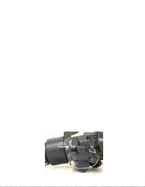
3-2. Activation (IR/pull position) (g.5a):
• To turn the unit on, turn the switch one click clockwise.
• Pull the switch out (switch is partially spring-loaded) and rotate one additional click clockwise to the IR
position. The Night Optics logo will appear for a few seconds in the display. The active thermal image
will then be displayed.
3-3. Reset/O-ON-IR/pull Power Switch (g.5a):
When the switch is in the OFF position, the NO/TG-7 is not energized.
3-4. Focus adjustment (g. 6d):
First, carefully rotate the objective lens clockwise or counterclockwise to sharpen focus. The user should
be able to focus from a minimum of three feet (3 ft) to a maximum of innity. Next, focus each eyepiece,
in accordance with your specic optical correction. Close one eye and rotate the eyepiece to adjust for
the sharpest image of the temp reading in the upper right hand corner. Close the other eye and repeat
the process. Finally, slide either or both of the eyepieces towards or away from your nose so that one
distinct image is viewed.
CAUTION
Do not touch the lens face
fig.5
(a)
Page 10
CHAPTER 3: SYSTEM CONTROLS
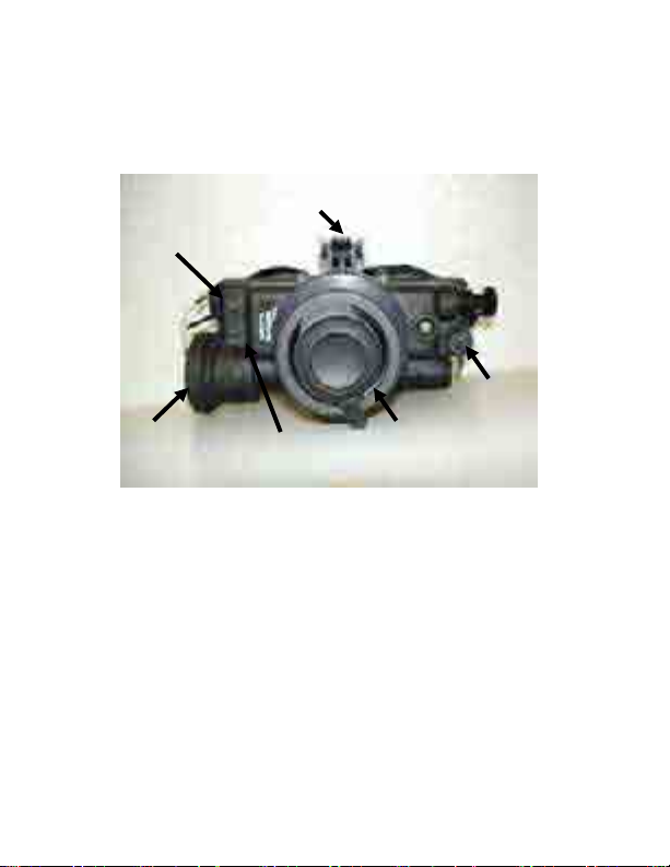
3-5. White-Hot/Black-Hot button switch (g. 6a):
The NO/TG-7 always starts in the white-hot mode. The NO/TG-7’s white hot/black hot polarity is
selected by using the bottom spring-loaded button on the front-right side of the unit. Briey
press the bottom button to switch between WHITE-HOT and BLACK-HOT polarities.
Latch
(b)
(c)
(a)
fig. 6
3-6. 2X Digital Zoom (g. 6b):
The 2X switch is a digital zoom that switches the unit from 1.5X to 3X when the top button is
depressed. When changing from 1.5X to 3X the objective focus will need to be adjusted slightly
for optimal performance. The unit always starts in the 1.5X mode.
3-7. Head Mount Assembly with Brow Pads (g. 2c, g. 3d):
Adjustable head assembly that secures the NO/TG-7 to the operator’s head providing
hands-free operation.
(d) (e)
Page 11

CHAPTER 4. RECEIPT, DEACTIVATION, CLEANING AND STORING THE SYSTEM
4-1. Service upon receipt of material
a. Inspect the equipment for possible damage incurred during shipment. If the equipment has been
damaged, contact Night Optics USA, Inc. immediately.
b. One of the bottom screws on the Back Plate is sealed. Breaking the seal invalidates the warranty.
Ensure the seal is intact before using.
Breaking the seal on the Back Plate (see b above) invalidates the warranty.
c. Check the equipment against the packing list to ensure the shipment is complete. Report all
discrepancies immediately to Night Optics USA, Inc.
d. The NO/TG-7 Thermal Goggle should be ready for use upon receipt and insertion of batteries as
prescribed in Chapter 3.
4-2. Deactivation:
Turn o the system by rotating the switch two clicks counterclockwise (CCW) to the OFF position. View
through the eyepiece to conrm the system is indeed o. Verify that the LED Indicator is not illuminated,
either RED or GREEN.
4-3. Battery removal (g. 6e):
Unscrew the battery compartment hatch, remove all three CR123 batteries, and store in the carrying case
or bag. Close the battery compartment. If disposal of the batteries is required, please follow your
organization’s hazardous materiel disposal procedures.
4-4. Cleaning outer unit
Use a moistened clean cloth to wipe the outside of the NO/TG-7, EXCEPT FOR THE OPTICAL SURFACES. A
very dilute detergent solution is permissible. Dry with a soft clean cloth, or allow unit to air-dry before
storing.
4-5. Cleaning optics
Clean lens surfaces only when visibly dirty. Avoid touching any exposed lens faces as skin acid from
ngerprints can damage coatings and lenses. After blowing air across the surface to remove any sand or
abrasive particles, clean any residue on the optical surfaces with a soft cotton cloth and mild neutral soap
diluted with lukewarm distilled water (1 part soap to 100 parts water), followed by reagent-grade
isopropyl alcohol swab. Remove dust gently with an alcohol swab.
Note: Avoid swabs that incorporate plastic stems.
4-6. Purging:
The housing of the NO/TG-7 goggle is lled with dry nitrogen and sealed to prevent dirt and moisture
from degrading performance during use.
Purging is not user level maintenance. Contact Night Optics or your Support Maintenance
WARNING
DO NOT BREAK THE SEAL.
WARNING
activity.
Page 12

CHAPTER 5. SYSTEM OPERATIONS
The NO/TG -7 is designed to be used as a hand-held, helmet-mounted or headmounted thermal system
that runs on battery or external power for extended operations. It is also unique in allowing the user to
stream active video to a laptop, video display or other device while being used. Because the NO/TG-7
does not have menu options, it is very user friendly.
5-1. Display Graphics
There are three indicators seen while viewing the display with the screen active: temperature, crosshair
and low battery.
• Temperature: Located in the upper right corner of the display screen. Displays the temperature of the
scene that is in the center eld of view dependent on the distance between the viewer and the object
being viewed. It is not the actual temperature of an object at its location. This can be used to help
locate an object not readily viewable.
• Battery: Visible in the lower right hand corner of the display screen. Indicates the approximate level
of remaining battery power.
5-2. Operation with External Power
There are 2 button switches located on the right side of the TG-7 goggles. They control the 2x
digital magnication, black hot/white hot polarity, brightness and contrast.
• Polarity/Contrast Control: Lower Button (g. 6a) With one button push the scene changes
from hot objects appearing white against a darker background to hot objects appearing dark
against a lighter (white) background. Contrast is activated by holding the button down until a
red, slowly blinking LED is seen in the left eyepiece at the 9 o’clock position. While the LED is
blinking use either button to increase or decrease the level of contrast between Black/white
• Digital 2x Magnication/Display Brightness: Upper Button (g. 6b) One button push will
magnify the scene by 2 power (2x). Display brightness is activated by holding the button down
until a red, rapidly blinking LED is seen in the left eyepiece at the 9 o’clock position. Adjust the
display brightness by while the LED is blinking.
Note: Control will revert back to Polarity/Digital Magnication if no adjustments are made for
approximately 2 seconds.
5-3. Operation with External Power
The NO/TG-7 can be powered for extended periods of time by the external power cable attached to a
source between 6-24 VDC. The internal batteries need not be removed during this operation. Before
attaching the EPC (g. 5b) to an active external power source - e.g., cigarette lighter, vehicle power port,
or power converter/inverter - ensure that the NO/TG-7 is turned completely o!!!
Sequence for connecting external power:
1. Turn power switch on NO/TG-7 to OFF position.
2. Connect the IPVC to the external IPVC jack (g. 6c); observe proper alignment of the plug and jack.
3. Connect the EPC to the “12V DC IN” port on the IPVC.
4. Connect the EPC to the external power source port on the IPVC.
5. Turn on the NO/TG-7.
WARNING
Do not connect the NO/TG-7 to any external power source while the unit is turned ON.
Sequence for disconnecting external power: Reverse the connection sequence to properly disconnect
external power.
Page 13

CHAPTER 5. SYSTEM OPERATIONS CONT
5-4. Operation using Video Output Cable (VOC)
One of the unique features of the NO/TG-7 is its ability to stream live video to a laptop,
camcorder, or video display without interfering with operations. This mode of operation gives
the operator the advantage of providing live thermal images to others via the web or of
retaining those images for future use.
Sequence for connecting video output:
1. Turn power switch on NO/TG-7 to the OFF position.
2. Connect the IPVC to the external IPVC jack (g. 6c); observe proper alignment of the plug
and jack.
3. Connect the VOC to the “VIDEO IN” port on the IPVC.
4. Connect the VOC to the device (laptop, camcorder, video display, etc).
5. Turn on the NO/TG-7.
Sequence for disconnecting video output: Reverse the connection sequence to properly
disconnect video output.
IPVC w/Cable
EPC
VOC
Page 14

CHAPTER 7. OPERATOR PREVENTIVE MAINTENANCE CHECKS AND TROUBLESHOOTING
7-1. Preventive Maintenance Checks: The table of Preventive Maintenance Checks provides
inspection criteria t o ensure proper operator-level mainten ance of the NO/TG-7 system and required
evacuation for additional maintenance services.
Seq
Interval
Item to Check
Procedure
Evacuate to
Maintenance if:
1
Before/
After
Optical surfaces
Inspect all lenses for dirt, fingerprint
residue, chips or cracks. If necessary,
clean and dry len ses as prescribed in
4-5 above.
Scratches or cracks
hinder vision with
goggle turned on, or if
cracks are present.
2
Before/
After
External surfaces
Inspect for cracks or damages.
Scratches and gouges are OK if
operation is not affected.
Cracked or damaged.
3.
Before/
After
Battery
compartment
Ensure battery cap, battery cap
retainer and o-ring are present.
Cap or o-ring is missing
or contacts are
damaged or corroded.
4.
Before/
After
Diopter
Adjustment
Rings
Rotate diopter rings to ensu re
eyepieces move freely and are not
loose. Range is alm ost ½ turn.
Binding, not moving
freely or too loose.
5.
Before/
After
Eyecups
Inspect for: dirt, cracke d or torn cups;
bent, broken or improperly fitting
eyecup ring. If necessary, clean with
water.
6.
Before/
After
Interpupillary
Adjustment
Slide each eyepiece back and forth to
check for binding or looseness.
Inability to achieve o r
maintain interpupillary
adjustment.
7.
Before/
After
Object lens
focus.
Rotate objective lens to ensure free
movement (range is approximately
1/3 turn).
Not free moving.
8.
Before/
After
RESET/OFF-ONIR/PULL Switch
Knob
Remove any batteries and turn the
switch knob from RESET/off to ON to
IR/PULL. Each pos ition should have a
definite stopping point. Inspect for
broken or missing knob.
Switch has no definite
stopping points or
knob broken or
missing.
9.
Before/
After
Latch
Inspect for damag e.
Damaged.
10.
Before/
After
Neck cord and
Lens Cap
Inspect for cracked , torn, or missing
lens cap. Inspect co rd for cut,
damage, or frayed ends. Re-tie ends if
necessary.
11.
Before/
After
Viewed image.
With fresh batteries inserted, turn ON
as per 3-2.
12.
Before/
After
Lenses
Inspect for indication of moisture
inside housing.
Any indication of
moisture inside
housing.
The operator of the NO/TG-7 is restricted to the simple cleaning of the exterior body and optical
surfaces; exchange of batteries; and replacement of the objective lens- cap, eyepiece and neck lanyard.
Refer all other discrepancies to support maintenance. If the equipment malfu nction is not listed or
actions listed do not correct the fault, notify the next higher echelon of maintenance or Night Optics
USA, Inc.
Page 15

Chapter 7. Operator Preventive Maintenance Checks and Troubleshooting (cont’d)
Discrep ancy
Probab le Cause(s)
Corrective A ction
7-2. Follo wing is a list of possible discrepa ncies, their possib le causes, and suggested operato r
procedu res to correct them:
Unit will not turn on Discharg ed batteries.
Unit will not turn on
No disp lay through eyepie ce
Partial s cene
Foggy or fu zzy picture Dirty or g reasy eyepiec e.
Scene out of focus
Undene d scene Moistur e in system.
Optics h ard to turn, o r grinding Dirty th reads. Evacuat e to mainten ance.
Batteries installed
backwa rds.
Objectiv e lens-cap s till
on.
Mud or debris on
objectiv e lens.
Incorrect lens/diopter
setting(s).
Replace and discard old
batteries.
Reinstall with proper
orientat ion.
Remove.
Remove/c lean per cleaning
procedu re.
Clean w ith wet & dry lens
paper. R ecommend using
Demist Shield.
Refocus objective, then
diopter settings.
Return t o maintenan ce facility
for nitroge n purging.
Recommend u sing Demist
Shield.
Page 16

APPENDIX A: ELE CTRONIC BLOCKDIAGRAM
ZOO M
PO LAR IT Y
OF F
ON LC D
ON TH ER MA L
AS 362 0
Power S upply
Video out
D+
D-
+3V
Ex ternal P ower
LC D drive r
Low B attery
LC D
LC D
 Loading...