

Page 1
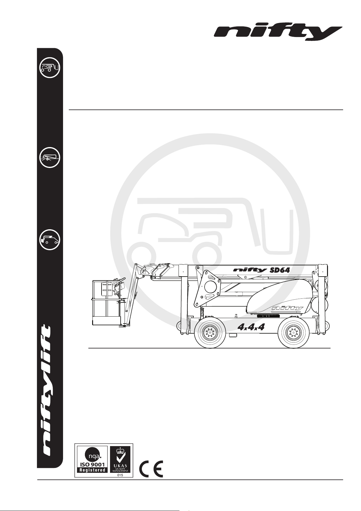
SD64
Operating & Safety Instructions
MODEL SD64 SERIES
.com
i n f o @ n i f t y l i f t . c o m
M50407/04
SCALE1.000
Niftylift Limited
1525 S. Buncombe Road
Greer
SC 29651
USA
www.niftylift.com
e-mail: [email protected]
Tel: 864-968-8881
Fax: 864-968-8836
Page 2

Page 3

SD64 Series
1
Operating & Safety Instructions
Table of Contents
1 Introduction and General Information 2
1.1 FOREWORD 2
1.2 SCOPE 3
1.3 INTRODUCING THE NIFTYLIFT SELF-DRIVE (SD) SERIES 3
1.4 GENERAL SPECIFICATION 4
1.5 IDENTIFICATION (USA PLATE) 6
1.6 EC DECLARATION OF CONFORMITY (Typical) 7
2 Safety 8
2.1 MANDATORY PRECAUTIONS 8
2.2 ENVIRONMENTAL LIMITATIONS 11
2.3 NOISE AND VIBRATION 12
2.4 TEST REPORT 12
3 Preparation and Inspection 13
3.1 UNPACKING 13
3.2 PREPARATION FOR USE 13
3.3 PRE-OPERATIONAL SAFETY CHECK SCHEDULES 14
3.4 PLACARD, DECALS & INSTALLATION 17
3.5 TORQUE REQUIREMENTS 20
4 Operation 21
4.1 CONTROL CIRCUIT COMPONENTS 21
4.2 SETTING UP PROCEDURES 23
4.3 GROUND CONTROL OPERATION 24
4.4 BASKET CONTROL OPERATION 27
4.5 DRIVING CONTROLS 31
4.6 OUTRIGGERS 32
4.7 BASKET WEIGH SYSTEM (Optional) 33
4.8 TRANSPORTING, TOWING, CRANEAGE, STORAGE AND SETTING TO WORK 34
5 Emergency Controls 37
5.1 GENERAL 37
5.2 IN THE EVENT OF AN INCAPACITATED OPERATOR 37
5.3 IN THE EVENT OF MACHINE FAILURE 37
5.4 TOWING 39
5.5 INCIDENT NOTIFICATION 42
6 Responsibilities 43
6.1 CHANGES IN OWNERSHIP 43
6.2 MANUAL OF RESPONSIBILITIES 43
6.3 INSPECTION/SERVICE/PRE-HIRE CHECK LIST 44
USA – 04/16
Issue 04
Page 4

SD64 Series
2
Operating & Safety Instructions
1 Introduction and General Information
1.1 FOREWORD
The purpose of these manuals is to provide the customer with appropriate safety operating and
maintenance instructions essential for proper machine operation.
All information in these manuals should be READ and fully UNDERSTOOD before any attempt is made
to operate the machine. THESE MANUALS ARE VERY IMPORTANT TOOLS - Keep them with the
machine at all times.
The manufacturer has no direct control over machine application and use, therefore conformance with
good safety practices is the responsibility of the user and his operating personnel.
All information in these manuals is based on the use of the machine under proper operating conditions.
Alteration and/or modification of the machine are strictly forbidden.
One of the most important facts to remember is that any equipment is only as safe as those who
operate it.
DANGER, WARNING, CAUTION, IMPORTANT, INSTRUCTIONS AND NOTICE
Any place these topics may appear, either in this manual or on the machine, are defined as follows:
DANGER: If not correctly followed there is a high probability of serious injury or death to personnel.
WARNING OR CAUTION: If not correctly followed there is some possibility of serious injury or death to
personnel.
THE 'SAFETY ALERT' SYMBOL IS USED TO CALL ATTENTION TO POTENTIAL
HAZARDS THAT MAY LEAD TO SERIOUS INJURY OR DEATH, IF IGNORED.
IMPORTANT AND INSTRUCTIONS: Denotes procedures essential to safe operation and prevention of
damage to or destruction of the machine.
NOTICE: Indicates general safety rules and/or procedures relating to the machine.
It is the owner's/user's responsibility to know and comply with all applicable rules, regulations, laws,
codes and any other requirements applicable to the safe use of this equipment.
USA – 04/16
Issue 04
Page 5

Operating & Safety Instructions
3
1.2 SCOPE
These operating instructions contain all the necessary information required to allow the safe operation
of any Niftylift SD64 4x4x4, powered by a diesel (D) engine.
For further technical information, circuit diagrams and specific instructions for all maintenance which
may need to be carried out by specialist trained personnel, see the associated Workshop and Parts
manual for your model of Niftylift Self-Drive.
1.3 INTRODUCING THE NIFTYLIFT SELF-DRIVE (SD) SERIES
Please note at the time of going to press all information, illustrations, details and descriptions contained
herein are valid. Niftylift reserves the right to change, alter, modify or improve its products without any
obligations to install them on previously manufactured machines.
If, after reading this manual you require further information, please do not hesitate to contact us at your
nearest office.
SD64 Series
Niftylift Inc, 1525 S. Buncombe Road, Greer, SC 29651 USA
Driven from the basket, the Niftylift SD64 4x4x4 is an extremely versatile articulated boom platform of
unique and simple design. It is capable of placing two men and their tools up to a working height of
69ft 7in or an outreach (past outriggers) 32ft 2in.
High traction or ground sensitive pneumatic tires and powerful hydraulic wheel motors give
unsurpassed performance with the option of fast drive speed when the booms are in the drive position.
High drive isolation and audible alarms activated by a ten-degree tilt sensor help to prevent the operator
from working on unsafe terrain whilst driving using the high-drive function.
The Niftylift SD64 4x4x4 provides a fast, safe, cost effective method of access, both inside and out, for
a multitude of applications where overhead working is required
Models include the following:
D: - DIESEL
USA – 04/16
Issue 04
Page 6

SD64 Series
4
FEATURE
SD64 4x4x4
MAXIMUM HEIGHT - WORKING
70ft 2in
MAXIMUM HEIGHT - BASKET
64ft
MAXIMUM HEIGHT – STOWED
(Galaxy 33/1550-16.5 Tires)
7ft 3in
MAXIMUM HEIGHT – STOWED FOR TRANSPORTING
(Galaxy 33/1550-16.5 Tires)
7ft 5in
MAXIMUM LENGTH - STOWED
21ft 2in
MAXIMUM LENGTH – STOWED FOR TRANSPORTING
17ft 11in
MAXIMUM OUTREACH – PAST OUTRIGGERS
35ft
MAXIMUM WIDTH – STOWED
(Galaxy 33/1550-16.5 Tires)
6ft 7in
MAXIMUM CAPACITY
500lbs
TURRET TAIL SWING
0ft 0in
TRAVEL SPEED – LOW REVS
2.2mph
TRAVEL SPEED – HIGH REVS
4.7mph
BASKET SIZE – LENGTH x WIDTH
68in x 28in
GROUND CLEARANCE - DRIVING
12in
GROSS VEHICLE WEIGHT
9083lbs
TURRET ROTATION
355º
CONTROL SYSTEM
Fully Proportional Booms
HYDRAULIC PRESSURE – BOOMS
3190 psi
HYDRAULIC PRESSURE – DRIVE
3625 psi
TIRES – SIZE
Trelleborg 380/55-17
TIRES – PRESSURE
32 psi
MAXIMUM FLOOR LOAD ON ONE FOOT
7194 lbf
MAXIMUM PRESSURE ON ONE FOOT
7725 lb/ft2
MAXIMUM FLOOR PRESSURE/WHEEL @ 32 psi
3968 lb/ft2
Operating & Safety Instructions
1.4 GENERAL SPECIFICATION
USA – 04/16
Issue 04
Page 7
SD64 Series
5
FEATURE
SD64 4x4x4
GRADEABILITY
45%
24º
TRAVERSING SLOPE
17%
10º
FUEL TANK CAPACITY
21 US gallons
TURNING RADIUS (INSIDE) – 2 WHEEL STEER
11ft 10ins
TURNING RADIUS (INSIDE) – 4 WHEEL STEER
5ft 3ins
CONTROL SYSTEM VOLTAGE – MAXIMUM
12V
CURRENT – MAXIMUM
125A
PULL FORCE – MAXIMUM AT BASKET
400N
90lbf
TILT ANGLE - BOOMS
0º
TILT ANGLE - DRIVE
10º
ENGINE – KUBOTA 1505D
25kW
33.5hp
Operating & Safety Instructions
USA – 04/16
Issue 04
Page 8
SD64 Series
6
Operating & Safety Instructions
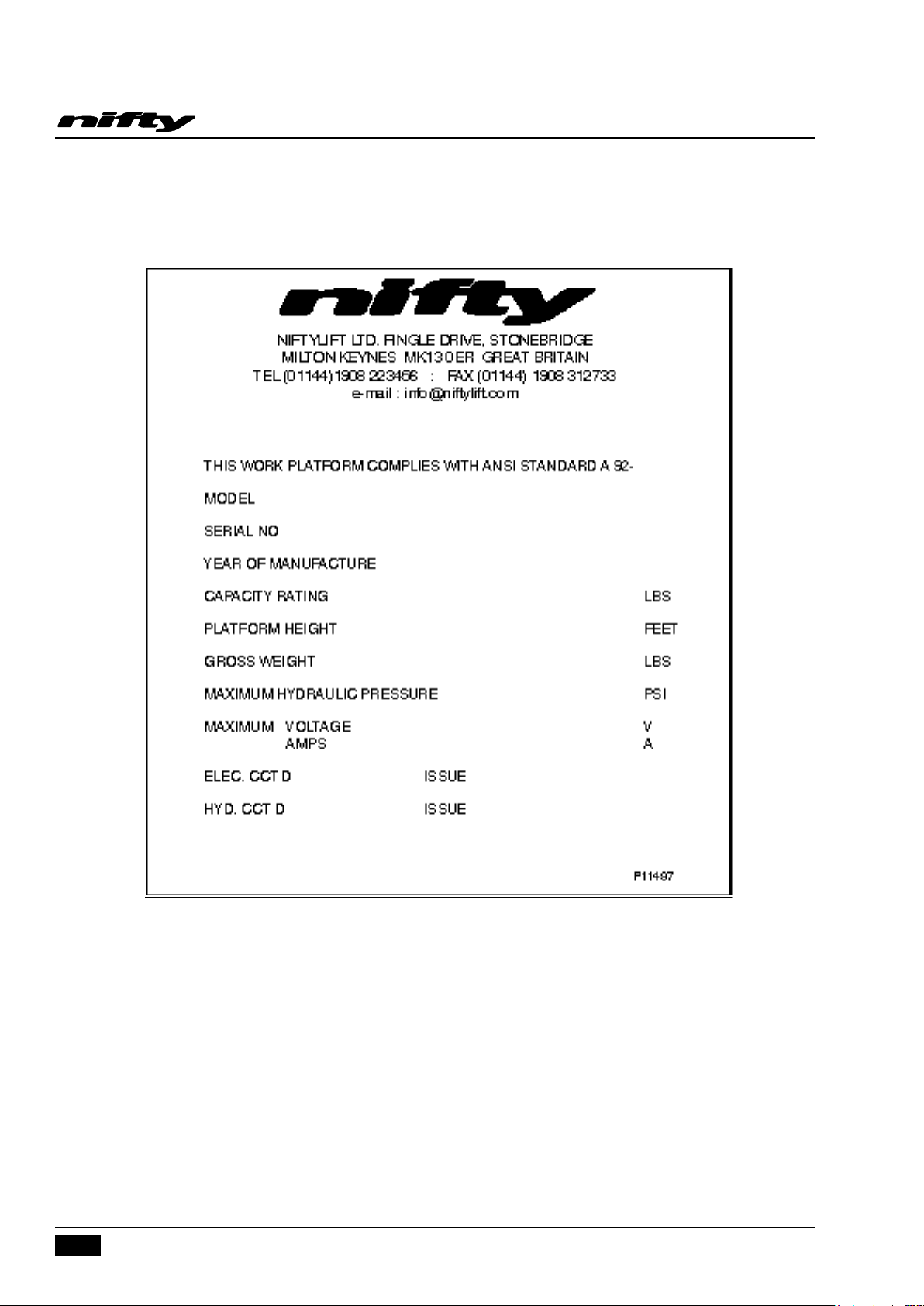
1.5 IDENTIFICATION (USA PLATE)
This manufacturer’s plate is attached to the Base on each machine at the time of
manufacture on every Niftylift. Please ensure all sections have been stamped and are legible.
USA – 04/16
Issue 04
Page 9
Operating & Safety Instructions
7
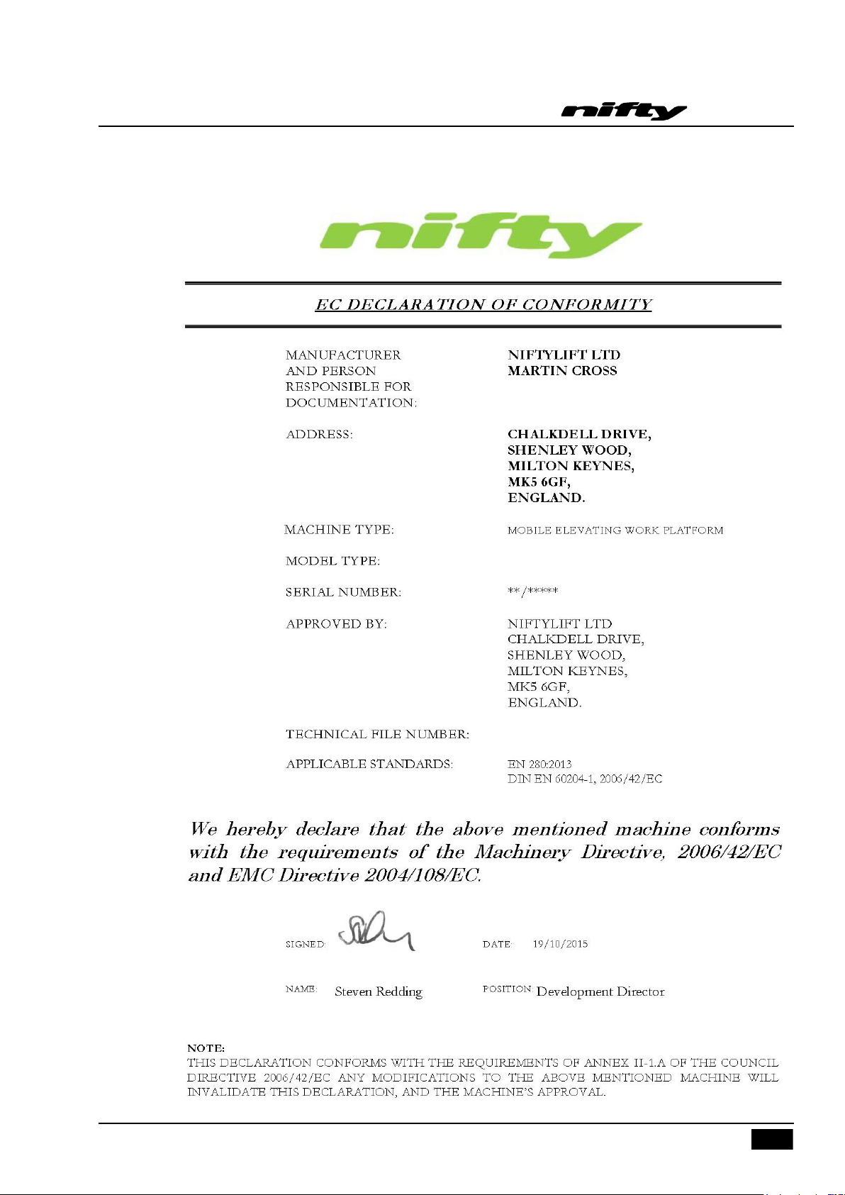
1.6 EC DECLARATION OF CONFORMITY (Typical)
SD64 Series
USA – 04/16
Issue 04
Page 10

SD64 Series
8
Operating & Safety Instructions
2 Safety
2.1 MANDATORY PRECAUTIONS
When operating your Niftylift, your safety is of utmost concern. In order to fully appreciate all aspects
of the machine’s operation it should be ensured that each operator has READ and fully UNDERSTOOD
the relevant manual covering machine use, maintenance and servicing. If any doubts exist concerning
any points covered in your manual, contact your local dealer or Niftylift Ltd.
Before using any Niftylift, thoroughly inspect the machine for damage or deformation to all major
components. Likewise, check the control systems for hydraulic leaks, damaged hoses, cable faults or
loose covers to electrical components. At no time should damaged or faulty equipment be used Correct all defects before putting the basket to work. If in doubt, contact your local dealer or Niftylift Ltd
(see front cover for address).
THE MANUFACTURER HAS NO DIRECT CONTROL OVER THE MACHINE
APPLICATION AND USE. THEREFORE CONFORMATION WITH GOOD SAFETY
PRACTICES IS THE RESPONSIBILITY OF THE USER AND HIS OPERATING
PERSONNEL. FAILURE TO UNDERSTAND AND FOLLOW ALL SAFETY RULES
COULD RESULT IN SERIOUS INJURY OR DEATH.
2.1.1 Only trained persons will be permitted to operate the Niftylift.
2.1.2 Always operate the Niftylift in full accordance with the manufacturer’s Operating & Safety Instructions
for that model.
2.1.3 Before use each day and at the beginning of each shift the Niftylift shall be given a visual inspection
and functional test including, but not limited to, operating and emergency controls, safety devices,
personal protective clothing, including fall protection, air, hydraulic and fuel system leaks, cables and
wiring harness, loose or missing parts, tires and wheels, placards, warnings, control markings and
Operating and Safety Manuals, guards and guard rail systems and all other items specified by the
manufacturer.
2.1.4 Any problems or malfunctions that affect operational safety must be repaired prior to use of the basket,
with specific regard to any safety components refer to the Parts Manual for part numbers and details. If
in doubt, contact Niftylift Ltd (Details on page 3).
2.1.5 Always ensure that all warning labels, instructions, placards, control markings and Safety Manuals are
intact and clearly legible. If replacements are required contact your local dealer or Niftylift. Always
observe and obey safety and operating instructions on such labels.
2.1.6 Do not alter, modify or disable in any way the controls, safety devices, interlocks or any other part of
the machine.
2.1.7 Before the Niftylift is used and during use the user shall check the area in which it is to be used for
possible hazards such as, but not limited to, uneven ground drop-offs, holes, bumps, obstructions,
debris, floor and overhead obstructions, high voltage conductors, wind and weather, unauthorised
persons and any other possibly hazardous conditions.
2.1.8 Never exceed the maximum basket capacity, as indicated on the decals and machine serial plate.
USA – 04/16
Issue 04
Page 11
SD64 Series
9
Operating & Safety Instructions
2.1.9 Never position any part of the Niftylift within the Minimum Approach Distances of any electrical power
line, conductor, or similar stated in Occupational Safety and Health Administration Regulations for CFR
1910.333(c) for Minimum Approach Distance for electrical wires.
1910.333(c)(3)(i)(A)(1): For voltages to ground 50kV or below - 10 feet (305 cm);
1910.333(c)(3)(i)(A)(2): For voltages to ground over 50kV - 10 feet (305 cm) plus 4 inches (10 cm) for every 10kV over 50kV.
THIS MACHINE IS NOT INSULATED.
If in doubt, contact the appropriate authorities.
2.1.10 On entering the basket ensure that the sliding midrail is fully down in its correct “closed” position.
2.1.11 Use of an approved safety belt and lanyard, hardhat and appropriate safety clothing is strongly
recommended for operator safety. Fasten harness to designated harness securing points within the
basket and do not remove until leaving the basket whilst in the stowed position.
Always remain standing within the basket. Do not attempt to increase your height or
reach by standing and/or climbing on the basket guardrails or any other object. KEEP
YOUR FEET ON THE BASKET FLOOR. Do not sit, stand or climb on the guardrail, mid
rail or boom linkage. Use of planks, ladders or any other devices on the Niftylift for
achieving additional height or reach is prohibited.
2.1.12 Do not use the basket levelling system to artificially increase the outreach of the Niftylift. Never use
boards or ladders in the basket to achieve the same result.
2.1.13 Do not use the basket to lift overhanging or bulky items that may exceed the maximum capacity or
carry objects that may increase the wind loading on the Niftylift. (e.g. Notice boards etc.)
2.1.14 The Niftylift shall not be operated from a position on trucks, trailers, railway cars, floating vessels,
scaffolds or similar equipment unless Niftylift Ltd in Great Britain approves the application in writing.
2.1.15 Always check below and around the basket before lowering or rotating the booms to ensure that the
area is clear of personnel and obstructions. Care should be taken when rotating the booms out into
areas where there may be passing traffic. Use barriers to control traffic flow or prevent access to the
machine.
2.1.16 Stunt driving or horseplay, on or around the Niftylift, shall not be permitted.
2.1.17 When other moving equipment and vehicles are present, special precautions shall be taken to comply
with local ordinances or safety standards established for the work place. Warnings such as, but not
limited to, flags, roped off areas, flashing lights and barricades shall be used.
2.1.18 Under all travel conditions the operator shall limit travel speed according to conditions of ground
surface, congestion, visibility, slope, location of personnel and other factors causing hazards of
collision or injury to personnel.
2.1.19 The Niftylift shall not be driven on grades, side slopes or ramps exceeding those for which the
manufacturer rates the aerial basket.
2.1.20 The aerial platform is not equipped for or intended for use on a public highway.
USA – 04/16
Issue 04
Page 12

SD64 Series
10
Operating & Safety Instructions
2.1.21 It shall be the responsibility of the user to determine the hazard classification of any particular
atmosphere or location. Aerial platforms operated in hazardous locations shall be approved and of the
type required. (For the USA refer to ANSI/NFPA 505)
2.1.22 The operator shall immediately report to his supervisor any potentially hazardous location(s)
(environment) which become evident during operation.
2.1.23 If an operator encounters any suspected malfunction of the Niftylift or any hazard or potentially unsafe
condition relating to capacity, intended use or safe operation he shall cease operation of the Niftylift
and request further information as to safe operation from his management, or owner, dealer or
manufacturer before further operation of the Niftylift.
2.1.24 The operator shall immediately report to his superior any problems or malfunctions of the Niftylift,
which becomes evident during operation. Any problems or malfunctions that affect the safety of
operation shall be repaired prior to continued use.
2.1.25 The boom and basket of the Niftylift shall not be used to jack the wheels off the ground.
2.1.26 The Niftylift shall not be used as a crane.
2.1.27 The Niftylift shall not be positioned against another object to steady the basket.
2.1.28 Care should be taken to prevent rope, electric cords and hoses from becoming entangled in the Niftylift.
2.1.29 Batteries shall be recharged in a well-ventilated area free of flame, sparks or other hazards (e.g. do not
smoke near the machine) that may cause explosion. Highly explosive hydrogen gas is produced during
the charging process.
2.1.30 When checking electrolyte levels great care should be taken to protect eyes, skin and clothing. Battery
acid is highly corrosive and protective glasses and clothing is recommended.
2.1.31 When the machine is not in use always stow the booms correctly. NEVER LEAVE THE KEYS IN THE
MACHINE, if it is to be left for any period of time. Use wheel chocks if leaving on an incline.
2.1.32 If the basket or elevating assembly becomes caught, snagged or otherwise prevented from normal
motion by adjacent structure or other obstacles, such that control reversal does not free the basket, all
personnel shall be removed from the basket safely before attempts are made to free the basket using
ground controls.
2.1.33 The engine must be shut down while fuel tanks are being filled. Fuelling must be done in a well-
ventilated area free of flame, sparks or any other hazard that may cause fire or explosion. GASOLINE
LIQUID PROPANE AND DIESEL FUELS ARE FLAMMABLE.
NEVER START THE NIFTYLIFT IF YOU SMELL GASOLINE, LIQUID PROPANE OR
DIESEL FUEL. THESE FUELS ARE HIGHLY FLAMMABLE.
2.1.34 The operator must ensure that engine powered machines are used in a well-ventilated area to minimise
the risk of carbon monoxide poisoning.
2.1.35 The operator shall implement means provided to protect against use by unauthorised persons.
2.1.36 Never remove anything that may affect the stability of the machine such as, but not limited to, batteries,
covers, engines, tires or ballast.
USA – 04/16
Issue 04
Page 13
SD64 Series
11
Operating & Safety Instructions
2.1.37 The operator must ensure that the controls are not obstructed (e.g. by tools or equipment) and clear
access to the Emergency Stop is available at all times.
2.1.38 All persons in the basket must take suitable precautions to prevent items falling or being ejected from
the basket. E.g. Tethering tools to the machine or operator if practical and an assessment of any
resulting risks is acceptable.
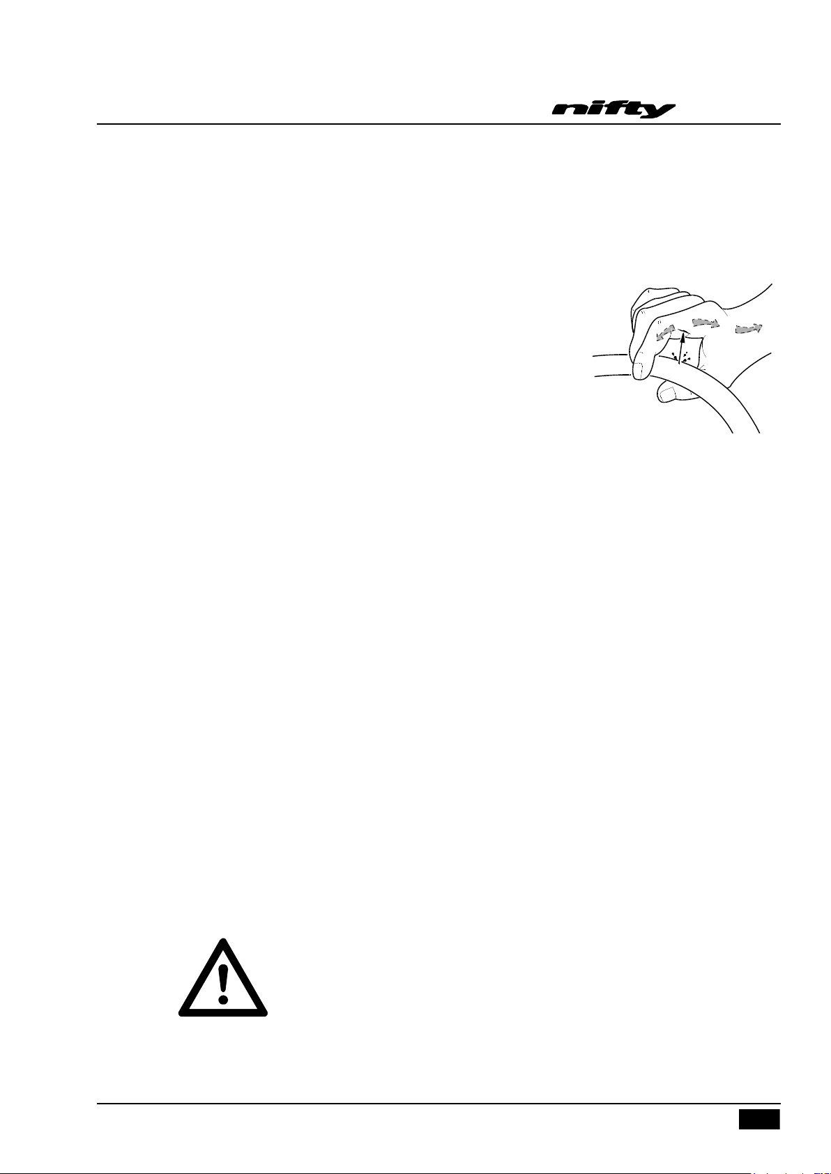
2.1.39 Hydraulic oil escaping under pressure can penetrate the skin and
cause serious injury. Do not allow hydraulic oil to squirt or spray.
Seek immediate medical attention in the event of hydraulic oil
penetrating the skin. Wear chemical-resistant protective gloves
and suitable eye protection when handling hydraulic oil. Relieve
system pressure before removing any hydraulic connections, undo
fittings slowly to make sure there is no residual pressure. If pressure
is detected, allow it to be released slowly before completely
removing hose. Fluid leaks may not be visible to the naked eye. Use
a piece of cardboard to check for leaks, not your hand. Never install hydraulic lines or components that
are damaged.
2.2 ENVIRONMENTAL LIMITATIONS
Unless specifically configured otherwise, the machine will have a short operational time in extreme
temperatures such as freezers and cold storage, due to reduced battery performance. For electrical
cables and components, the temperature must be within the range -5°C to 60°C.
The machine is limited in high temperatures because of the cooling requirement for engines and
hydraulic oil. Coolant temperatures must be within the range -37°C to 110°C (at 50% mixture of water
to anti-freeze). Oil temperature is not to exceed –23°C to 93°C.
The recommended operational range for these machines is - 5°C to +40°C. Please contact
Niftylift Ltd for special considerations if the machine is required to operate outside these
temperatures.
Extended operation in dusty environments is not recommended and frequent cleaning will be
necessary. All dust, dirt, salt encrustation, excess oil or grease should be removed. Deposits of paint or
bitumen, particularly on legends or labels should also be removed.
All standard Niftylift machines are rated for a wind speed of 28mph or force 6 on the Beaufort scale. No
attempt should be made to operate a Niftylift in wind strengths above this limit and if the operator has
any doubts over the wind speed he / she should cease operation immediately until it can be established
that the wind speed has fallen to a safe level.
DO NOT USE THE NIFTYLIFT IN ELECTRICAL STORMS.
USA – 04/16
Issue 04
Page 14

SD64 Series
12
Operating & Safety Instructions
2.3 NOISE AND VIBRATION
The airborne noise emission on the Self-drive range of machines does not exceed 79dB(A), measured
at a perpendicular distance of 4m, under equivalent continuous A-weighted sound pressure test
conditions. This was based on a Diesel powered machine, working under load. All other models will
exhibit significantly lower emissions than this figure, dependant on power option.
In normal operation the Vibration level to which the operator is subjected will not exceed a weighted
root mean square acceleration value of 2.5 m/s2.
2.4 TEST REPORT
All Niftylift machine models are subjected to a comprehensive ‘type test’ which duplicates all
combinations of safe working load (SWL), overload, windage, inertia and pull force to assess the
various safe stability criteria. Self propelled machines are also subjected to kerb and braking tests at
the SWL to satisfy additional ‘worse case’ stability requirements.
Each individual machine is then subjected to static overload tests on flat level ground with 150% of the
SWL, exceeding the requirements of EN280 for power operated MEWPs. Self propelled machines are
also tested at the maximum working angle plus 0.5º with a test load of 125% of the SWL. Finally, on all
machines, a functional test is performed with 110% of SWL.
All safety devices are checked for correct operation, operating speeds are checked against benchmark
figures and the dynamic functions ensure that all acceleration and deceleration forces are within
acceptable limits. All noted defects are rectified and recorded before the machine is permitted to enter
into service.
USA – 04/16
Issue 04
Page 15
SD64 Series
13
Operating & Safety Instructions
3 Preparation and Inspection
3.1 UNPACKING
Since the manufacturer has no direct control over the shipping or carriage of any Niftylift it is the
responsibility of the dealer and/or owner and/or leaser to ensure the Niftylift has not been damaged in
transit and a Pre-operational Report has been carried out by a qualified engineer before the aerial
basket is put into service.
1) Remove all ropes, straps and or chains used to secure the aerial basket during transit.
2) Ensure any ramp, loading dock or forklift used is capable of supporting or lifting the aerial
basket.
3) If the Niftylift is to be driven off, please ensure that the operator has read and fully understood
this entire manual. Refer to the appropriate section for precise operating instructions.
***Carry out the Pre-operational Report before placing machine in service.
3.2 PREPARATION FOR USE
Whilst every effort has been made at the Niftylift factory to ensure your machine
arrives in a safe and operable condition it is necessary to carry out a systematic
inspection prior to putting the Niftylift into service.
THIS IS NOT A REQUEST IT IS MANDATORY.
To assist the user in this task you will find enclosed an Inspection Check List (see section 6.3), which
must be filled out upon delivery/receipt of the machine.
Before the user carries out the Inspection Check List he must have read and fully understood all the
contents of the Operating, Safety and Maintenance Manual.
WARNING - DO NOT OPERATE A POTENTIALLY DEFECTIVE OR
MALFUNCTIONING MACHINE. CORRECT AND REPAIR ANY DEFECTS BEFORE
OPERATING YOUR NIFTYLIFT.
USA – 04/16
Issue 04
Page 16

SD64 Series
14
Operating & Safety Instructions
3.3 PRE-OPERATIONAL SAFETY CHECK SCHEDULES
Before use at the beginning of the work shift, the Niftylift shall be given a visual inspection and
functional tests including, but not limited to the following. It is recommended that these be performed at
regular intervals as indicated on each checklist.
3.3.1 DAILY SAFETY CHECKS
1) Check that all labels (decals) are in place and legible.
2) Visually inspect the machine for damaged or loose components.
3) If fitted, check that batteries are charged (if applicable) i.e. Charger has a solid green light and a
pulsing red light.
4) Check the fuel level (if applicable).
5) Check that canopies/covers and guards are in place and secure.
6) Check that the boom rest switch is operable.
7) Check that control levers are secure and operate freely.
8) Check that operating buttons and emergency stop buttons function properly.
9) Check the operation of the emergency hand pump.
10) Visually inspect all hydraulic hoses and fittings for damage or leaks.
11) Check operation of the outrigger alarm.
12) Check that outrigger footpads are secure.
13) Check that the basket pivot pins and their swing bolts are secure.
14) Check that SiOPS is functioning correctly (Refer to Section 4.4.2).
15) Check the operation of the basket weigh system (If fitted). See section 4.7.3 for testing and
verification procedure.
3.3.2 WEEKLY SAFETY CHECKS
1) Inspect tires and wheels for damage and wear.
2) Check tires for correct pressure. 32 psi (2.2 bar)
3) Check suspension and dampers for damage and leaks.
4) Check that the joystick is secure.
5) Check battery fluid levels and specific gravity (after charging) and general condition.
6) Check hydraulic oil level, Grade 32.
7) Inspect the engine air filter and clean or replace if necessary.
8) Check operation and security of outrigger micro switches in conjunction with the alarm system.
9) Inspect hose track for damage or missing parts.
USA – 04/16
Issue 04
Page 17

15
3.3.3 MONTHLY SAFETY CHECKS
1) Check the engine oil level (if applicable).
2) Check the wheel nuts (torque 110ft lbs / 150Nm).
3) Check that the bolts holding the wheel motors to the chassis are secure.
4) Check outriggers for condition, security and operation.
5) Check that the rotation gear worm is secure and correctly in mesh. Clean and re-grease.
6) Grease the rotation gear and worm gear.
7) Inspect the engine fuel tank for damage or leaks.
8) Check telescopic boom wear pads and nylon studs (if applicable).
9) Check and adjust if necessary the Nylatron studs around the telescope boom.
10) If fitted, every three months check and verify the calibration of the basket weigh system. See
section 4.7.4 for the calibration procedure.
SD64 Series
Operating & Safety Instructions
11) Every Six months perform a thorough examination in accordance with the ‘Lifting Operation
and Lifting Equipment Regulations’ (LOLER) 1998, Regulation (9)(3)(a).
3.3.4 ANNUAL SAFETY CHECKS
1) Check that all pivot pins and their swing bolts are secure.
2) Inspect for any cracks or badly rusted areas on booms and chassis.
3) Change the hydraulic oil and the oil filters.
4) Check the bushes in the front wheel hubs for wear.
5) Check that ringbolts are secured (torque 220ft lbs. / 300Nm).
Toughcage
Niftylift toughcage is fully UV stabilised for outdoor use in the most demanding climates. However, the
user and machine owner should consider the following;
Discolouration of the material may occur; this is a natural aging process which does not
significantly alter the material properties.
Degredation to the floor may occur as a consequence of product use and effect of UV exposure.
The toughcage’s multi-layer construction means degradation of the top surface may occur over
time without compromising the structural strength of the internal and base layers.
The rate at which the toughcage floor ages is dependant upon the machines application and its
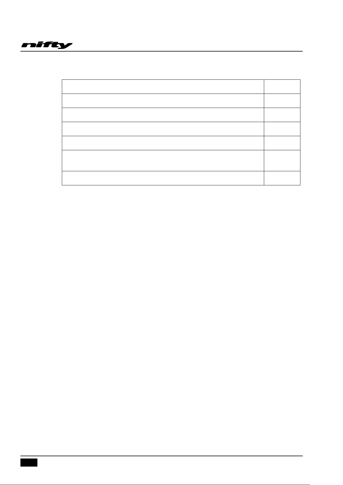
country of use (Typical levels of UV exposure). Refer to table below for aging rate applicable to your
specific area.
USA – 04/16
Issue 04
Page 18
SD64 Series
16
UK, NETHERLANDS, GERMANY, POLAND, SCANDINAVIA, CANADA, RUSSIA
14 years
FRANCE, ITALY, USA (NORTH EAST STATES)
11 years
SPAIN, GREECE, TURKEY, CHINA, USA (MID WEST STATES), AUSTRALIA (TASMANIA)
9.5 years
MALAYSIA, INDONESIA
8 years
USA (SOUTH STATES), SOUTH AMERICA, AUSTRALIA (VICTORIA, NEW SOUTH WALES)
7.5 years
USA (WEST STATES), SOUTH AFRICA, INDIA, PAKISTAN, IRAN, AUSTRALIA (WESTERN,
SOUTH, QUEENSLAND)
7 years
NORTH AFRICA, SAUDI, DUBIA, AUSTRALIA (NORTHERN TERRITORY)
6 years
Operating & Safety Instructions
Note: The date of manufacture of the toughcage floor is located on its underside.
Niftylift recommends that the user and machine owner regularly inspect the toughcage floor for
damage. If any significant damage is found then the floor must be replaced. For further guidance please
contact Niftylift Limited.
USA – 04/16
Issue 04
Page 19

17
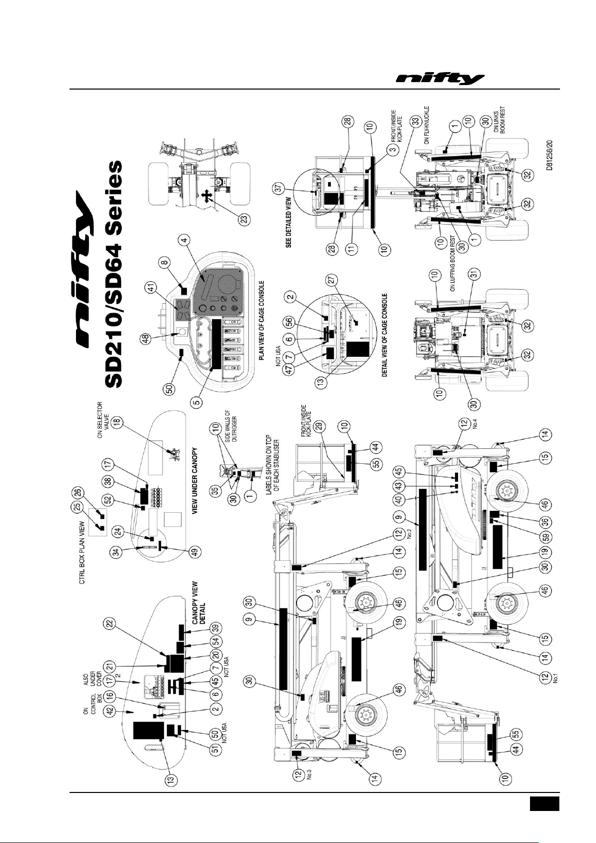
3.4 PLACARD, DECALS & INSTALLATION
ITEM
DESCRIPTION
NUMBER
QTY
1
No Step
P14785
6 2 E-Stop Warning
P14864
2
3
Footswitch
P14884
1
4
Cage Control Panel
P23666
1
5
Hydraulic Controls – 6 Levers
P14020
1
6
If Tilt Alarm Sounds
P18842
2
7
Overload Warning
P18848
2
8
Head Protection
P14921
1
9
Nifty SD64 - Grey
P19421
2
10
Hazard Tape
A/R
11
Niftylift.Com
P14390
2
12
‘1,2,3,4’ Grey
P17000
1
13
General Warning
P24900
2
14
Tie Down Points
P17556
4
15
Outriggers Warning
P14841
4
16
Base Controls
P16752
1
17
Hydraulic Controls – 6 Levers
P22042
2
18
Booms/Drive Selector
P23093
1
19
4x4x4 - Grey
P17437
2
20
Daily Safety Check List
P14908
1
21
Battery - Isolator
P18600
1
22
Battery Drain
P19850
1
23
Travel Directions
P14784
1
24
Hydraulic Oil
P17226
1
25
Trip – Push To Reset
P19056
1
26
Electric Luffing/Levelling
P17559
1
27
Read Manual
P14892
1
28
Harness Points
P14883
2
29
Swl 225 Kg
P17328
1
30
General Crush
P14782
10
31
Diesel
P14414
1
32
Jack Point
P17557
4
33
10 Degree Lateral Tilt
P21049
1
34
Oil Level
P14676
1
35
Point Load – 25 kN
P17558
4
36
Serial Plate
P15383
1
37
Cage Gate Warning
P18335
1
38
Manual Descent
P19605
1
39
Chain Inspection
P16535
1
SD64 Series
Operating & Safety Instructions
USA – 04/16
Issue 04
Page 20

SD64 Series
18
40
Noise Warning
P17124
1
41
Outrigger Controls
P19192
1
42
General Notice
P21941
1
43
Hot surfaces/Moving machinery
P22314
1
44
Cage Tie-Down Warning
P21404
2
45
Rotating Machinery (USA)
P15010
2
46
Gearbox Disengage
P19180
4
47
SiOPS Instructions
P22820
1
48
Horn
P23739
1
49
Pressurised Tank
P16365
1
50
Clunk Click
P19961
2
51
IPAF Are you trained?
P22055
1
52
Emergency Controls Location
P22877
1
54
Emergency Controls Location
P21700
1
55
ToughCage
P21816
2
56
Objects on Controls
P21511
1
59
Compliance statement (USA)
P25250
1
Operating & Safety Instructions
USA – 04/16
Issue 04
Page 21
SD64 Series
19
Operating & Safety Instructions
USA – 04/16
Issue 04
Page 22

SD64 Series
20
BOLT QUALITY/SIZE
Tightening torque in lbs ft (Nm)
Plated
Unplated
Grade
8.8
10.9
12.9
8.8
10.9
12.9
M 6
5 (7)
8 (10)
9 (12)
6 (8)
8 (11)
10 (13)
M 8
13 (17)
18 (25)
22 (29)
14 (19)
20 (27)
23 (32)
M 10
25 (34)
36 (49)
43 (58)
27 (37)
40 (54)
46 (63)
M 12
43 (58)
63 (85)
73 (99)
47 (63)
69 (93)
80 (108)
M 14
68 (93)
100 (135)
117 (158)
74 (101)
109 (148)
127 (172)
M 16
106 (143)
154 (209)
180 (245)
115 (156)
168 (228)
197 (267)
M 20
212 (288)
301 (408)
352 (477)
224 (304)
328 (445)
384 (521)
M24
362 (491)
515 (698)
602 (806)
383 (519)
561 (760)
656 (889)
WHEEL NUTS
110 ft lbs (150 Nm)
WHEEL MOTOR NUTS
99 ft lbs (135 Nm)
SLEW RING BOLTS
220 ft lbs (300 Nm)
Operating & Safety Instructions
3.5 TORQUE REQUIREMENTS
This torque chart is based on the following assumptions:
1) Bolts to ISO 898-1 "Mechanical properties of fasteners made of carbon steel and alloy steel"
2) For "unplated" bolts, all grades:
Hex head bolts
Black oxide steel bolt with a rolled & oiled thread, no finish on steel nut
Prevailing torque includes Nylock (minimum prevailing torque figure assumed)
Medium Clearance holes to ISO 273
Bolt tightening condition = Yield factor of 75%
3) For "plated" bolts, all grades:
Hex head bolts
Zinc plated oiled (rolled or cut) steel external thread with no finish on steel internal thread
Prevailing torque includes Nylock (minimum prevailing torque figure assumed)
Medium Clearance holes to ISO 273
Bolt tightening condition = Yield factor of 75%
Figures quoted in Nm have been calculated in Nm and then rounded to the nearest whole number.
Figures quoted in lb-ft have been calculated in Nm, converted using a factor of 0.737561 and then
rounded.
USA – 04/16
Issue 04
Page 23
SD64 Series
21
Operating & Safety Instructions
4 Operation
4.1 CONTROL CIRCUIT COMPONENTS
4.1.1 MAIN CONTROL BOARD: - Situated under the left-hand superstructure cover, the encapsulated control
board comprises a PCB (printed circuit board) design that incorporates all of the circuit to control the
machine operation. The control boards are common to all models, and contain functions that might not
be utilised on your particular machine.
4.1.2 BASKET OVERLOAD: If the Niftylift is fitted with a basket overload sensing device located between the
basket bracket and the basket itself. This device is preset at the factory and must only be reset or
adjusted by a qualified Niftylift representative. If the basket payload of 500lbs is exceeded, the sensor
will immediately shut off the diesel engine preventing further use of the machine. The diesel engine
cannot be restarted until the payload is reduced to a mass of 500lbs or less.
4.1.3 TILT ALARM: - There is a 10 tilt alarm fitted to the superstructure underneath the base controls cover,
which is a solid-state sensor that monitors the inclination of the machine. This tilt alarm operates a
sounder and warning lamp on the basket control panel warning the operator that the machine is
operating on a slope greater than or equal to 10º. Great care must be taken at all times when
manoeuvring any machine on slopes greater than 10º. If in any doubt as to the stability of the
machine whilst operating across a slope partially deploy the downhill outriggers for additional safety.
WARNING – Continuing to drive across slopes in excess of a 10 inclination
with the tilt sensor activated could result in the machine rolling over causing
serious injury or death!
4.1.4 SOUNDER: - Situated on the front of the base control box is a small piezo electric sounder, which is
used to provide an intermittent alarm whenever the machine is in operation. Pushing the green "power
control" button, or depressing the foot switch in the basket (if fitted) will energise this sounder. This
serves to warn personnel of the operation of the machine.
4.1.5 HORN: - Located on the side of the base control box is a horn, which is used as a manual alert, by
pushing the "Horn" button at the Basket control position.
4.1.6 SIREN: - Also located on the side of the base control box is a device that sounds continuously if the Tilt
Alarm Sensor detects excessive inclination when the allowable ground slope is exceeded while driving.
It will also sound when the low fuel warning light comes on.
Lastly it will sound when any of the stabiliser feet lifts free from the ground.
4.1.7 MAIN CONTROL VALVE: - The main control valve contains the steer valve and the brake release
system. Should any of these functions require overriding, use the hand pump, (see Section 5.3).
4.1.8 BOOM CONTROL VALVE: - The boom control valve contains the ON/OFF solenoid and PRV for the
boom controls. Should any of these functions require overriding, use the hand pump, (see
Section 5.3).
4.1.9 BOOM-SWITCHES: - Mounted on the tele-knuckle and the booms down/centralising post located on
the top of the base, and operated by any of the booms raising and/or the telescopic boom extending,
these switches control both the operation of the Tilt Alarm Sensor, and the drive speed control function.
USA – 04/16
Issue 04
Page 24

SD64 Series
22
Operating & Safety Instructions
With the booms in the stowed position, the operator is allowed to drive the machine and negotiate
slopes up to 10 without activating the tilt alarm (Refer to 4.1.3).
Because of the restricted visibility over the engine canopy, an electric luffing switch has been provided.
Using this switch on the basket console permits the operator to elevate the luffing boom to a restricted
safe height for driving the machine thus providing better visibility.
Before elevating the booms, the operator must first deploy and set up each of the outriggers using the
switches on the basket console until the base is level. The level of the machine can be checked using
the spirit level located on top of the base. To ensure that all of the stabiliser feet are correctly deployed,
check that the light on each of the stabiliser switches has turned off.
Once the outriggers are correctly set up, the operator can use all boom functions. Should an outrigger
foot come clear of the ground, an audible siren will sound as well as a flashing warning light on the
basket console. Also the light on the switch that controls that particular outrigger will light up again
indicating which one has gone light. If this happens, return all booms to their stowed position. This will
return control to the outriggers allowing them to be reset.
4.1.10 BATTERY MANAGEMENT: - Under no circumstances should a machine be left fully discharged or
severe battery damage can occur in a relatively short time.
4.1.11 BATTERY ISOLATOR: - A battery disconnect plug is located beneath the base control canopy, which
allows the machine control and power circuits to be isolated from the batteries themselves. Under
normal operation, the machine Key Switch should be used to isolate the machine, with the Battery
Isolator plug only being required for emergencies to disconnect the batteries in the event of a short
circuit, or during servicing of the machine to ensure that the power is disconnected. The battery is
grounded to the chassis.
4.1.12 DIESEL ENGINE: -
1) 125A fuse near the diesel engine battery (starter motor and alternator).
2) 10A circuit breaker - (main control system).
3) 35A circuit breaker - (heavy-duty circuit for diesel throttle/Glow plug).
4) 15A circuit breaker – (all solenoid functions).
4.1.13 LOAD SENSING CONSOLE (SiOPS
senses if the operator has been pushed or has fallen against the console. If the load applied to the front
of the console is greater than the pre-determined amount, the footswitch will be disabled to increase
operator safety and reduce the possibility of sustained involuntary operation of the cage controls. For
further information refer to Section 4.4.2.
TM
) : - This machine incorporates a load sensing cage console that
USA – 04/16
Issue 04
Page 25
23
4.2 SETTING UP PROCEDURES
FAILURE TO DEPLOY THE OUTRIGGERS CORRECTLY COULD RESULT
IN DEATH OR SERIOUS INJURY.
ALL MODELS
1) Read and fully comply with all safety precautions and operating instructions in the Operating and
Safety manual and the warning decals on the machine.
2) Position Niftylift on firm ground, bearing in mind range of boom movement so that any overhead
obstructions or possible hazards such as, but not limited to, power cables, telephone lines,
drains, manhole covers, etc. can be safely avoided
3) If the load bearing capacity of the ground is in any doubt the machine must NOT be used.
4) Levelling the machine using the hydraulic outriggers can accommodate a slope of up to 12
degrees, if necessary using suitable load bearing pads to support the downhill jacks. Do not
elevate the platform unless the base can be corrected to within three degrees of level.
SD64 Series
Operating & Safety Instructions
5) Chock wheels and cordon off area using appropriate cones, barriers and flags.
6) Check all red emergency stops are not engaged i.e. fully out.
7) Ensure Base/Basket selector is turned up to basket position.
8) From the basket control station depress the footswitch to give hydraulic power to the outriggers.
Note: No power will be available if the booms are not stowed onto the boom rest.
9) Using the four outrigger control switches, lower each outrigger onto a firm, level surface and
level machine base ensuring each outrigger foot is taking equal weight with the wheels clear off
the ground. Each switch has a light that will turn off once the outrigger foot has been correctly
deployed.
10) Check machine is level using spirit level on the base, visible from the basket.
11) The booms can now be operated from the basket control station by depressing the footswitch.
Note: If no power is available check each outrigger is lowered and each footpad is taking equal
weight.
12) Always lower booms fully before adjusting, raising, retracting or moving the outriggers in any
way.
13) Never alter, modify or block any of the safety circuits on the Niftylift.
THIS MACHINE IS NOT ELECTRICALLY INSULATED. DO NOT WORK WITHIN
10FT OF OVERHEAD CABLES EXCEEDING 415 VOLTS
USA – 04/16
Issue 04
Page 26

SD64 Series
24
Operating & Safety Instructions
4.3 GROUND CONTROL OPERATION
ALWAYS ALLOW THE ENGINE TO WARM UP BEFORE OPERATION.
4.3.1 GROUND CONTROL INSTRUCTIONS
ALL MODELS
1) Check below, above and around the basket for any obstructions or hazards before operating any
function.
2) Ensure all red emergency stops are out.
3) Turn Base/Basket selector at ground control station to Ground (Clockwise).
DIESEL ENGINE
4) For a cold engine start go to step 5) or for a warm engine start go to step 6).
5) COLD ENGINE: - turn the Diesel Glow/Start selector to the Glow position (anti-clockwise). This
engages the glow plug pre-heat system. Hold for 3-5 seconds then turn the key to the Start
position (fully clockwise) and the engine will fire. If the engine doesn’t fire, then repeat this step
6) WARM ENGINE: - turn the Diesel Glow/Start selector to the Start position (clockwise) and the
engine will fire.
ALL MODELS
7) Push and hold green power button.
8) Select the boom function required and operate hand levers in full accordance with
manufacturer’s Operating and Safety manual.
9) To change control to the basket turn the Base/Basket selector to the Basket position (anti-
clockwise).
10) When not in use return machine to stowed position. Note: Fully lower the Link booms first
(Lever 4) followed by the Upper boom (Lever 5) for smooth operation. Fully raise and stow all
outriggers, turn the Base/Basket selector to the centre “OFF” position, remove key and chock
wheels.
EMERGENCY PROCEDURES
11) Push in red emergency stop to shut down all functions.
12) Use emergency hand pump (located under control canopy) to provide motive power and
manoeuvre the machine as normal using the hand levers (Basket or Base).
USA – 04/16
Issue 04
Page 27

SD64 Series
25
1 Emergency Stop
PUSH to stop machine
TURN CLOCKWISE to release
2 Diesel Glow/Start Selector
TURN ANTI-CLOCKWISE – Glow; Release or Off
TURN CLOCKWISE – Start positions
3 Basket Overload Alarm
Light ON – Payload in basket exceeds 225kg
4 Base/Basket Selector
UP for Basket Controls
DOWN for Base Controls
5 Green Power button
PUSH and hold to energise machine
Operating & Safety Instructions
BASE CONTROL STATION
BOOM FUNCTIONS
1) Push and hold green power button.
USA – 04/16
Issue 04
Page 28
SD64 Series
26
1 Operates Basket levelling
UP for backwards
DOWN for forward
2 Operates Flyboom
UP for up
DOWN for down
3 Operates Telescoping
UP for out
DOWN for in
4 Operates Links
UP for up
DOWN for down
5 Operates Luffing boom
UP for up
DOWN for down
6 Operates Boon Rotation
UP for right
DOWN for left
Operating & Safety Instructions
2) Select lever 1, 2, 3, 4, 5 or 6 for desired boom function.
ALWAYS ENSURE THE AERIAL BASKET IS ON A FIRM SURFACE AND THE AREA
IS FREE OF ANY OVERHEAD OBSTRUCTIONS.
ENGAGING THE RED EMERGENCY STOP BUTTON WILL SHUT DOWN THE
ENGINE AND THE ELECTRIC CIRCUIT PREVENTING OPERATION OF ANY
FUNCTION.
USA – 04/16
Issue 04
Page 29

27
4.4 BASKET CONTROL OPERATION
NEVER START THE NIFTYLIFT IF YOU SMELL GASOLINE, LIQUID PROPANE OR
DIESEL. THESE FUELS ARE FLAMMABLE.
BEFORE OPERATING THE NIFTYLIFT ENSURE THAT EACH OPERATOR HAS READ
AND FULLY UNDERSTOOD THE OPERATING MANUAL. FAILURE TO DO SO MAY
RESULT IN DEATH OR SERIOUS INJURY.
***FOR COLD START PROCEDURES SEE SECTION 4.4.1***
ALWAYS ALLOW THE ENGINE TO WARM UP BEFORE OPERATING.
4.4.1 BASKET CONTROL INSTRUCTIONS
ALL MODELS
1) NEVER exceed the maximum basket capacity.
2) Check below, above and around the basket for any obstruction or hazards before operating any
function.
SD64 Series
Operating & Safety Instructions
3) Ensure all red emergency stops are out.
4) Turn Base/Basket selector at ground control station to Basket (Anti-clockwise).
5) Turn selector switch (2) on basket controls to I (clockwise).
DIESEL ENGINE
6) For a cold engine start go to step 7) or for a warm engine start go to step 8).
7) COLD ENGINE: - turn the Diesel Glow/Start selector to the glow position (anti-clockwise). This
engages the glow plug pre-heat system. Hold for 3-5 seconds then turn the key to the Start
position (fully clockwise) and the engine will fire. If the engine doesn’t fire, then repeat this step
8) WARM ENGINE: - turn the On/Off Diesel Start selector to the Start position (clockwise) and
the engine will fire.
ALL MODELS
9) Depress the footswitch.
10) Select the boom function required and operate hand levers in full accordance with
manufacturer’s Operating and Safety manual.
11) To change control to the base turn the Base/Basket selector to the base position (clockwise).
12) When not in use return machine to stowed position. Note: Fully lower the Link booms first
(Lever 4) followed by the Upper boom (Lever 5) for smooth operation. Fully raise and stow all
outriggers, turn the Base/Basket selector to the centre “OFF” position, remove key and chock
wheels.
EMERGENCY PROCEDURES
1) Push in red emergency stop to shut down all functions.
2) Use emergency hand pump (located under control canopy) to provide motive power and
manoeuvre the machine as normal using the hand levers (Basket or Base).
USA – 04/16
Issue 04
Page 30
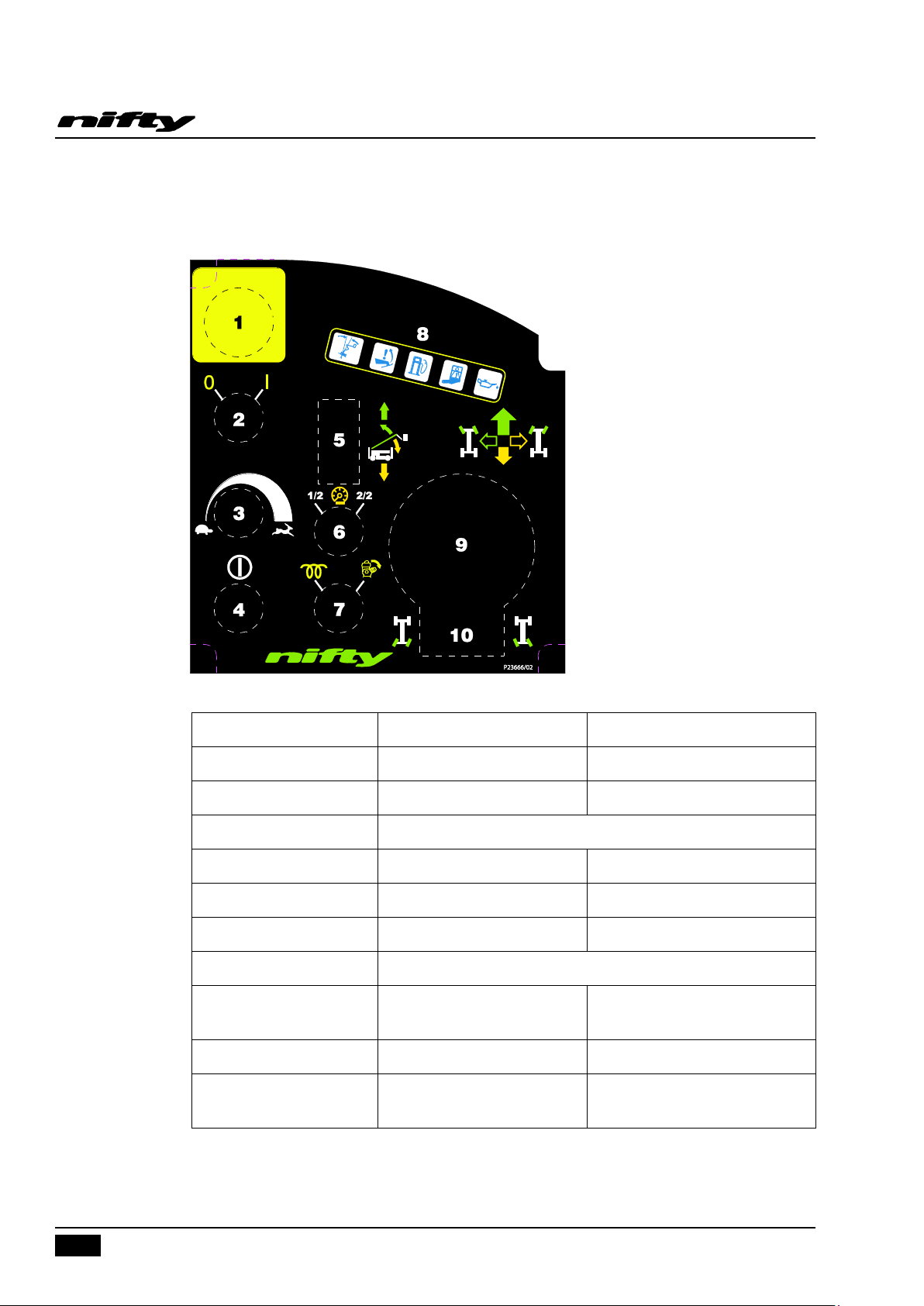
SD64 Series
28
1 Emergency Stop
Push to Stop machine
Turn clockwise to release
2 Cage enable
Left = OFF
Right = ON
3 Variable Speed Control
Clockwise increases speed
Anti-clockwise decreases speed
4 Green Power Button
Push to energise machine
5 Electric Luffing
UP to elevate luffing boom
DOWN to lower luffing boom
6 Hi/Low Engine Speed
Left = Low Revs
Right = High Revs
7 Diesel Glow/Engine Start
Left = Engine Glow
Right = Engine Start
8 Warning LED’s
Tilt; Leg light, Low Fuel; Cage Overload; Low Oil Pressure
9 Joystick
Switch on top of Joystick
Forward = Drive forward
Left = Left
Backward = Drive reverse
Right = Right
10 Rear Steer
Left = Left
Right = Right
Jackleg switches
(Above Control Panel)
Depress Outer Edge = Deploy
Depress Inner Edge = Retract
Operating & Safety Instructions
BASKET CONTROL STATION
USA – 04/16
Issue 04
Page 31
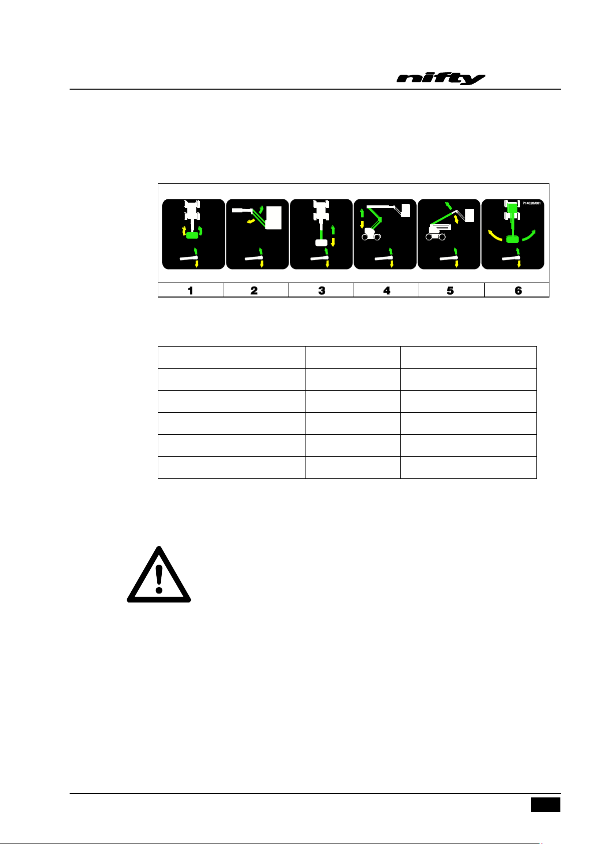
SD64 Series
29
1 Operates Basket Rotation
UP for clockwise
DOWN for anti-clockwise
2 Operates Flyboom
UP for up
DOWN for down
3 Operates Telescoping
UP for out
DOWN for in
4 Operates Links
UP for up
DOWN for down
5 Operates Luffing boom
UP for up
DOWN for down
6 Operates Boom Rotation
UP for right
DOWN for left
Operating & Safety Instructions
BOOM FUNCTIONS
1) Push and hold green "Power Control" button.
2) Select lever 1, 2, 3, 4, 5 or 6 for desired function.
4.4.2 SiOPS
This machine incorporates a load sensing cage console that senses if the operator has been pushed or
has fallen against the console. If the load applied to the front of the console is greater than the predetermined amount, the footswitch will be disabled to increase operator safety and reduce the
possibility of sustained involuntary operation of the cage controls.
Note: The green button will illuminate once the footswitch has been disabled, but continues to be
TM
- LOAD SENSING CONSOLE (If fitted)
WHEN OPERATING THIS MACHINE THE USER MUST BE AWARE OF ANY
OVERHEAD OBSTRUCTIONS.
available for use at all times. This allows the operator to use the cage control functions and
manoeuvre the machine to a safe position.
USA – 04/16
Issue 04
Page 32

SD64 Series
30
Operating & Safety Instructions
To reset the footswitch:
1) Release the load from the front of the console.
2) Ensure cage controls are in the neutral position and clear of objects.
3) Raise foot clear of footswitch then lower foot onto footswitch.
4) Footswitch is now active and full control has been restored.
Note: If SiOPSTM has been activated and the footswitch is not reset within 15 seconds, then the
blue warning beacon will flash (If fitted, located on underside of the cage) and a warning
announcement will sound until the footswitch is reset as described previously.
USA – 04/16
Issue 04
Page 33

31
4.5 DRIVING CONTROLS
Do not operate the Niftylift whilst elevated unless on a firm, level surface
free from any possible obstructions or hazards both at ground level and
overhead.
1) Using the electric luffing switch on the basket console, elevate the basket to the drive position
for better visibility. This elevates the basket approximately 1m above the ground.
2) Check proposed route for possible hazards, obstructions and personnel.
3) Depress switch located on the front of the joystick.
4) Use the Drive Speed selectors on the basket control station to determine speed.
1/2 (Tortoise) - gives low speed and low engine revs.
2/2 (Hare) - gives high speed and high engine revs.
Set the variable speed control knob as required.
SD64 Series
Operating & Safety Instructions
5) Select drive joystick located on the basket console.
Push forward for FORWARD DRIVE
Pull backward for REVERSE DRIVE
Front steering is controlled by the rocker-switch button on the top of the joystick
Left for STEER LEFT
Right for STEER RIGHT
Rear steering is controlled by the rocker-switch button located in front of the joystick
Left for STEER LEFT
Right for STEER RIGHT
All control levers give a fully proportional response therefore the more the lever is moved away from
the centre OFF position the faster the function will become.
Maximum drive speed is only attainable when the variable speed control knob is set to maximum and
the joystick is pushed fully forward.
When driving with the booms fully stowed, the Niftylift can be driven up and down slopes with an
inclination of 24. However, the tilt alarm operates a sounder and warning lamp on the basket control
panel, warning the operator that the machine is operating on a slope greater than or equal to 10º. Great
care must be taken at all times when manoeuvring any machine on slopes greater than 10º. If
in any doubt as to the stability of the machine whilst operating across a slope, partially deploy the
downhill outriggers for additional safety.
Under no circumstances should any SD64 series machine be driven on slopes exceeding the
gradeability in the general specification.
USA – 04/16
Issue 04
Page 34

SD64 Series
32
Operating & Safety Instructions
4.6 OUTRIGGERS
Before elevating the booms, the operator must first deploy and set up each of the outriggers using the
switches on the basket console until the base is level. The level of the machine can be checked using
the spirit level located on top of the base. To ensure that all of the outrigger feet are correctly deployed,
check that the light on each of the outrigger switches has turned off.
As soon as any one of the outrigger feet makes contact with the ground and starts taking load, then the
operating speed is reduced. This is to provide safer and smoother control of the outriggers.
Once the outriggers are correctly set up, the operator can use all boom functions. Should an outrigger
foot come clear of the ground while any of the booms are out of its stowed position, an audible siren
will sound as well as a flashing warning light on the basket console. Also the light on the switch that
controls that particular stabiliser will light up again indicating which one has gone light. If this happens,
return all booms to their stowed position. This will return control to the outriggers allowing them to be
reset.
USA – 04/16
Issue 04
Page 35
33
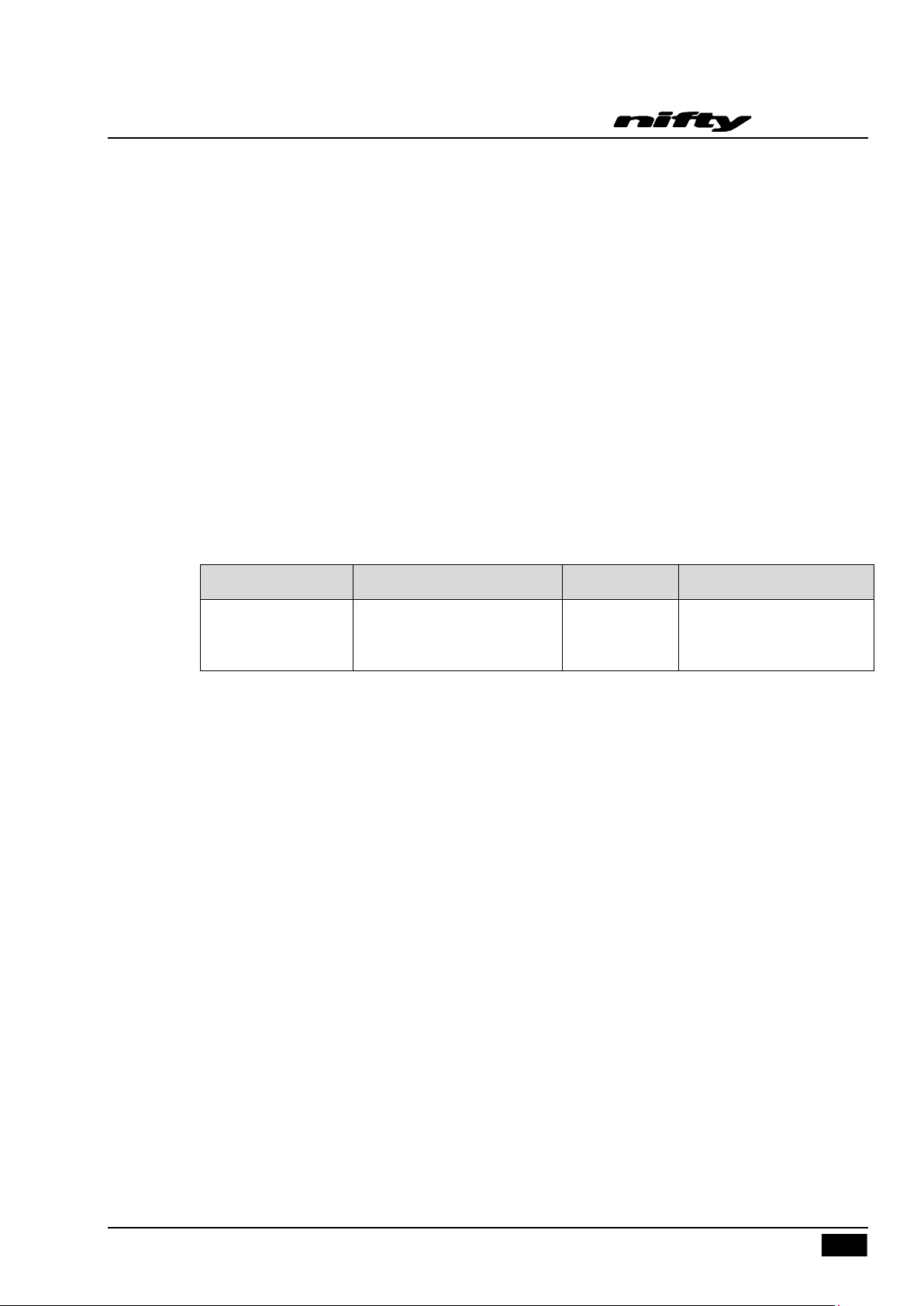
Lamp
Description
Load value
Machine Behaviour
Flashing red (Safety
Warning Lamp)
Load in the basket has
exceeded safe working load
Above 225kg
Controls isolated –
safely remove excess load
to restore normal operation
4.7 BASKET WEIGH SYSTEM (Optional)
4.7.1 LOAD CELL VERSION
The Niftylift SD210 is fitted with an electronic load cell. This load cell is a moment-independent,
redundant design. This means that independent of the load position inside the basket of the machine,
the actual load is measured and if pre-configured limit values are exceeded, warnings will be activated.
“Redundant design” means that the load cell design incorporates dual channels that monitor each
other. The design of the unit meets the requirements of both BS EN280 and ISO 13849 with a safety
integrity level of "Category 3 PL d.
4.7.2 FUNCTION
The machine informs the operator, via the load cell output, of the current state of the machine with
regard to basket load. The red lamps warning the operator of an overload condition are located on the
basket control panel (see section 4.4.1) and the base control panel (see section 4.3.1). Refer to
following table;
SD64 Series
Operating & Safety Instructions
4.7.3 CALIBRATION, INSPECTION AND MAINTENANCE
Calibration, maintenance and repair of the Niftylift SD210 basket load cell require specialist knowledge
and equipment. For this reason, no part of the electronic cage-weigh system can be adjusted,
repaired or inspected by the operator.
All enquiries relating to calibration, inspection or maintenance should be directed to Niftylift or one of
Niftylift’s approved dealers. Contact details are listed in Section 1.4.
USA – 04/16
Issue 04
Page 36

SD64 Series
34
Operating & Safety Instructions
4.8 TRANSPORTING, TOWING, CRANEAGE, STORAGE AND SETTING TO WORK
4.8.1 TRANSPORTING
If a Niftylift is to be moved over a longer distance, whether the machine is trailer mounted, vehicle
mounted, self propelled or tracked, the following procedure should be read before restraints are
attached to the machine. Cross loading is most frequently the cause of problems, as the method of
loading is no longer under the control of our own personnel. The recommendations made herein
should be passed on to subsequent carriers, such that the entire journey is carried out without incident.
Always ensure the truck or trailer you are loading or towing the Niftylift with can carry it legally.
If loading by crane the use of shackles and an adequately rated spreader beam, with four leg
slings around indicated slinging points on base, is MANDATORY.
When loading or un-loading from the side of the vehicle, the use of the forklift pockets to retain
one of the forks is recommended. (If fitted). Spread the forks to their widest capacity, with
due regard to the components fitted to the Niftylift. Never forklift or crane an entire Niftylift
under the booms, always lift beneath the spine or under the ends of the axle mountings in the
case of a self-propelled unit. Ensure forklift is adequately rated for the load to be carried.
Once positioned on the transport carrier, ratchet straps should be used to secure the Niftylift.
Pass the strap over the bosses located in the bottom of all four outrigger housings on the base
and secure to the transport carrier. The Niftylift should be positioned to allow easy access
around the machine in transit, and to ensure that ‘creepage’ during transport does not permit
the machine to come into contact with other goods being shipped, or the container itself.
Some movement of the Niftylift structure might occur during transit, which could lead to
fretting or other damage.
If the Niftylift is equipped with a transit device such as a boom clamp etc, this should be
securely applied.
Strap booms carefully to constrain them from sideways movement. When using straps or
chains, adequate packing should be applied to stop any damage to the structure and
paintwork. Due regard of the movement of the straps or chains must be taken into account.
Where a Niftylift has designated points for strapping, lifting or forking, these can be used for
tie-down duty. When they are absent, the major structure of the Niftylift can be used, giving
due consideration to the design and function of the area chosen. Where possible, use the
spine of the Niftylift or axle mounts over which to apply the holding down forces. Using a
single plate, such as an outrigger or stabiliser support plate might be unsuitable. If the
component was clearly not designed to accommodate a side load, one should not be applied.
Under no circumstances should straps or chains be applied over booms or through the basket
support structure or the basket itself. The relative strength of the carrying structure is not
conducive to the massive forces capable of being applied through ratchet chains or slings.
Severe damage to the steelwork can be caused, as well as deformation to sensitive
mechanisms such as basket weigh assemblies, which would render them useless. Such
catastrophic damage to say, an electronic load cell would require the component to be
replaced before the machine would function.
USA – 04/16
Issue 04
Page 37

35
4.8.2 TOWING
4.8.3 CRANEAGE
1) Observe all of the limitations relating to straps and chains stated above under ‘Transporting’.
(4.8.1)
2) When utilising the designated lifting points never apply a ‘snatch’ load, i.e. lift slowly to take up
the load before raising. Similarly, do not drop machine when positioning after lifting.
SD64 Series
Operating & Safety Instructions
DO NOT TOW MACHINE WITHOUT FOLLOWING THE TOWING PROCEDURE AS
DESCRIBED IN SECTION 5.4 OF THIS MANUAL.
3) If the machine is to be lifted by crane, use the designated lifting points and observe the
recommendations regarding spreader beams. Individual drawings are available for each machine
type, on request. (See list below.)
4.8.4 STORAGE
If being stored for any length of time without use, then the machine should be thoroughly inspected for
the following: -
1) Grease all bearings /slides, worm drives, etc.
2) If machine is to be left on an incline, chock wheels to prevent creep.
3) If machine is to be left outdoors or in a hostile environment, cover with suitable weatherproof
media to prevent deterioration.
D81489 SD34T
D80891 SD50
D81338 SD64
USA – 04/16
Issue 04
Page 38

SD64 Series
36
Operating & Safety Instructions
4.8.5 SETTING TO WORK
Before use each day and at the beginning of each shift the machine shall be given a visual and
functional test including, but not limited to, the following;
1) Check all lubrication points for adequate application of grease, oil etc.
2) Inspect all threads for ease or operation.
3) Check level and quantity of oil. Remove any contaminants - water, etc.
4) Check battery for electrolyte and state of charge.
5) Check electrics for damage and insulation.
6) Using base controls, cycle machine over complete envelope in accordance with the Operating
Instructions. Cure any defects.
7) Ensure that all safety devices and controls operate in accordance with the instructions.
8) If necessary, perform a load test to establish the machine stability before putting the Niftylift to
work.
9) On completion of an extended period of road transport, the Niftylift might need additional
inspection to identify any transit degradation, which could render the machine unsafe. Perform
a P.D.I. inspection on the unit before it enters service. Record any faults found and rectify them
immediately.
10) If left un-attended for an extended period, it is likely that the hydraulic basket levelling will
become un-pressurised. Normal operation is then lost, with a noticeable delay in the forwards or
backwards motion as the booms move. To restore normal function, the basket needs to be fully
levelled forwards and backwards, using the basket-levelling lever whilst not standing in the
basket (i.e. with the operator standing adjacent to the basket side whilst simultaneously
operating the lever and green button to move the basket). Take care not to become trapped
between the moving basket and a fixed object, and ensure those around you are clear of the
moving basket. When the system has been charged in both directions, the basket levelling
function should be restored. If the system operates but is ‘jerky’ in either direction, this
indicates air in the system. Repeat the procedure as described above until the movements are
smooth and un-interrupted. If in doubt, contact our Service Department for further advice.
Niftylift Limited is not liable for any third party damage caused during transport. Careful attention to
correct procedures will prevent many of the small snags that can happen in transit. Re-work is both
expensive and time consuming. A defective machine arriving at the place of work is a poor
advertisement for our product, the company’s reputation and those of our dealers and clients. The
responsibility for safe and damage-free transport rests with the haulier or his representatives.
USA – 04/16
Issue 04
Page 39
Operating & Safety Instructions
37
5 Emergency Controls
5.1 GENERAL
CHECKING THE OPERATION OF THE EMERGENCY CONTROLS EVERY DAY
AND/OR BEFORE EACH SHIFT IS AN ESSENTIAL PART OF THE OPERATOR'S
DUTIES
The operator and all ground personnel must be thoroughly familiar with the location and operation of
the EMERGENCY CONTROLS.
5.2 IN THE EVENT OF AN INCAPACITATED OPERATOR
Turn the Base/Basket Selector in the ground control station to ground (clockwise). Then lower on the
ground controls as detailed under section 4.3 Ground Control Operation.
5.3 IN THE EVENT OF MACHINE FAILURE
SD64 Series
Operate manual hand pump (located under control cover) and lower basket to the ground using either
basket or base controls. If initial movement of the machine allows the master alarm to reset, normal
controls will be available. This is then the fastest method of lowering the basket to the ground.
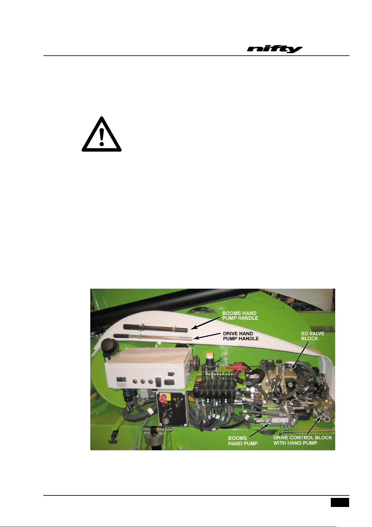
Opening the nearside machine canopy reveals the ground controls, plus the dedicated hydraulics for
emergency recovery of the machine.
Primarily there are two emergency hand pumps, the first is mounted separately and adjacent to the
ground control valve block and is used for the boom functions, jack legs and rear steer. The second
hand pump is incorporated into the Drive Control Valve Block and is used for the brake release and
front steering.
USA – 04/16
Issue 04
Page 40
SD64 Series
38
Operating & Safety Instructions
5.3.1 BOOM OVERRIDE
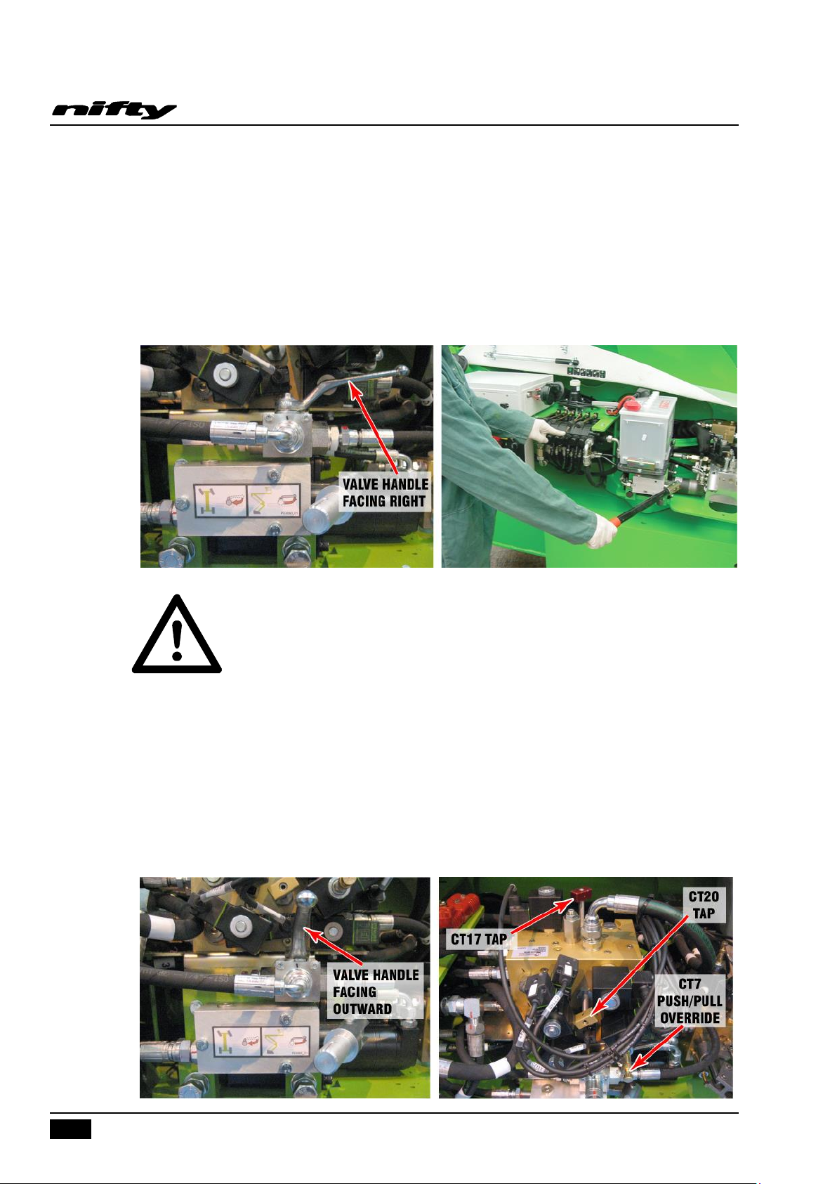
Ensure the Diverter Valve handle is turned to the right (see below). Operate the appropriate function,
and using the Booms Hand Pump, manoeuvre the booms as required. If desired, the Basket operator
can hold the appropriate lever to manoeuvre the machine, whilst a ground operative provides the
motive power using the booms hand pump. When not in use, the handle should be stowed back in its
clips.
FOLLOWING AN EMERGENCY DESCENT RECOVERY OF THE BASKET, FULLY
EXTEND AND RETRACT ALL CYLINDERS FROM GROUND CONTROL STATION
BEFORE USING THE MACHINE
5.3.2 REAR STEER OVERRIDE
Ensure the Diverter Valve handle is turned towards the operator (see below) and that the CT17 Tap
(Red) is fully open and either push the CT7 Override fully in and hold, or pull fully out and hold. Now
use the Booms Hand Pump to operate the rear steer function. The push or pull function of the CT7
Override determines either left or right steer operation. Return the handle to booms position (facing
right) to allow canopy to close. This ensures that the hand pump always defaults to ‘booms’ position
when needed’.
USA – 04/16
Issue 04
Page 41
39
5.3.3 FRONT STEER OVERRIDE
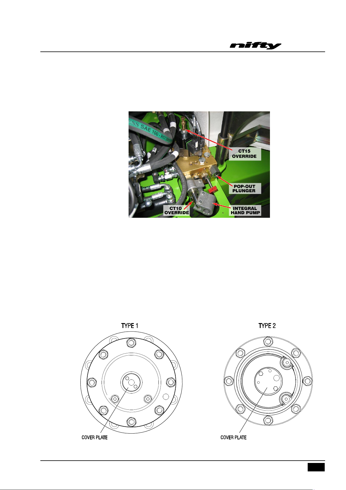
Push the CT15 Override fully in and hold, or pull fully out and hold. Now use the Integral Hand Pump to
operate the front steer function. The push or pull function of the CT15 Override determines either left or
right steer operation.
SD64 Series
Operating & Safety Instructions
5.4 TOWING
If the Niftylift needs to be towed in case of an emergency, it will be necessary to chock the wheels
before commencing gearbox disengagement.
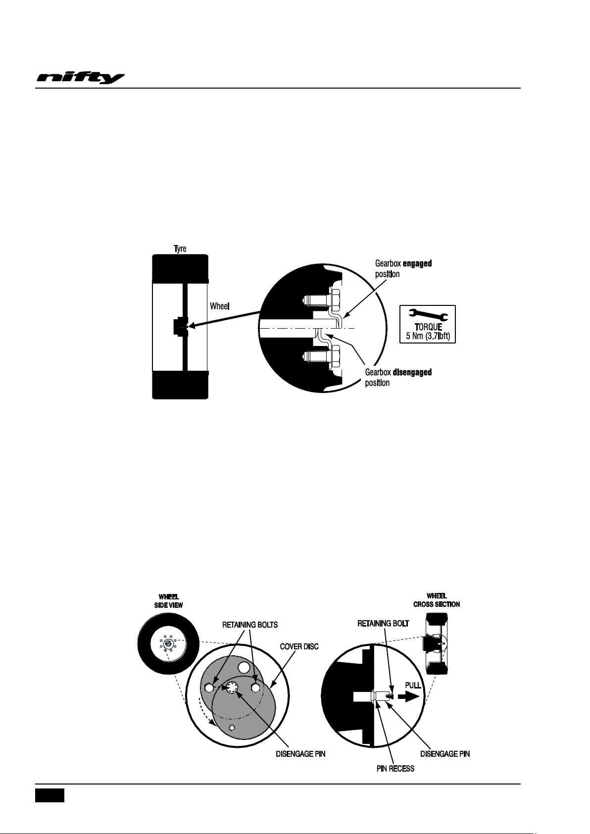
5.4.1 IDENTIFYING GEARBOX TYPE
In order to safely tow the SD210, the drive mechanism will need to be bypassed. Identify the type of
gearbox fitted to the machine then refer to the relevant procedure for disengagement of the gearboxes.
USA – 04/16
Issue 04
Page 42
SD64 Series
40
Operating & Safety Instructions
5.4.2 GEARBOX DISENGAGEMENT (TYPE 1)
The drive gearboxes located on the front and rear wheel hubs must be disengaged as follows;
1) To disengage the gearbox, remove both screws from the cover plate, turn it upside down (as per
the diagram below), re-tighten the M5 screws to a torque of 5 Nm (3.7lbft).
2) Before attempting to re-engage the gearbox, ensure that the machine is jacked up so the relevant
wheel is clear of the ground in order to prevent damage. Note; Damage caused by failure to
comply with this notice will not be covered by the manufacturer’s warranty.
5.4.3 GEARBOX DISENGAGEMENT (TYPE 2)
The drive gearboxes located on the front and rear wheel hubs must be disengaged as follows;
1) Remove both retaining bolts that secure the cover disc to the centre of the wheel hub.
2) Partially screw one of the retaining bolts into the end of the central disengage pin and pull the pin
out fully, ensuring the recess on the pin is visible.
3) Place the cover disc over the pin, ensuring the retaining disc is engaged in the pin recess and
secure in place using the remaining retaining bolt.
4) To re-engage the gearbox, complete the above instructions in reverse order, ensuring gearbox
drive is free to engage before pushing the pin ‘home’. If necessary, jack up each wheel & rotate
slightly to allow re-engagement of pin.
USA – 04/16
Issue 04
Page 43
41
5.4.4 BRAKE RELEASE FOR TOWING
To tow the machine it is necessary to bypass the parking brakes. First, ensure that the machine is
restrained against running away, i.e. suitably position the towing vehicle and attach a rigid tow bar to
the towing hoops located at both ends of the chassis and adequately chock on two or more wheels in
both directions. Moving the Niftylift must not be attempted until adequate means to prevent it
from rolling away are in place.
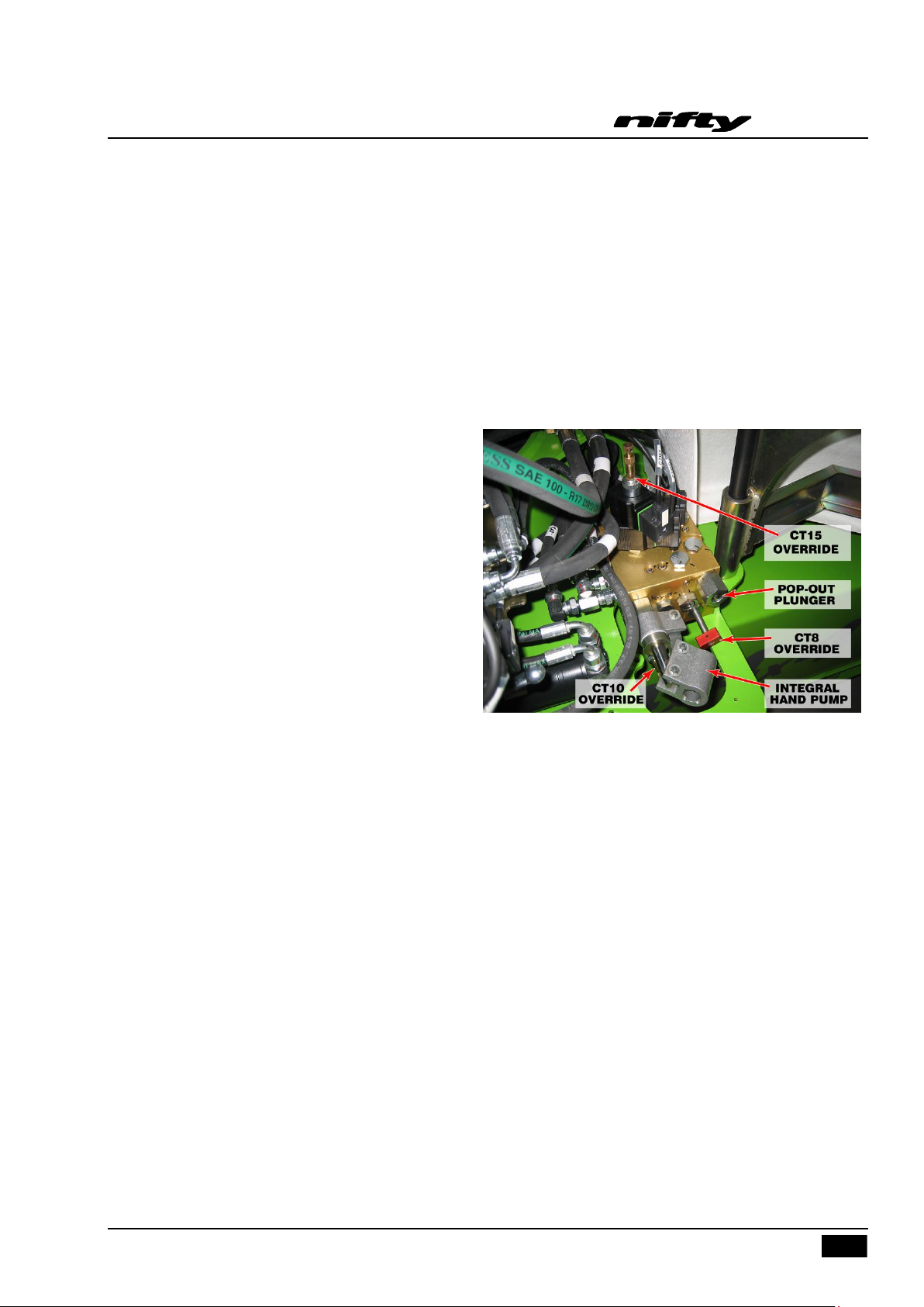
Fit the hand pump handle to the Integral Hand Pump. Push and hold down the CT10 Override whilst
pumping the handle. When brake pressure is generated, the brake Pop-Out Plunger will be exposed.
The brakes are now bypassed and the
Niftylift is capable of being towed at a low
speed.
To re-set the parking brakes, the CT8
Override Tap should be fully opened (turn
anti-clockwise). This is the red knob on
the side of the Drive Control Valve block.
Opening this knob allows the brake
pressure to dissipate from the bypass
circuit, re-setting the parking brakes and
de-energizing the tow valve. The Niftylift
will now lock the wheels and deny any
attempt at towing.
SD64 Series
Operating & Safety Instructions
Once complete ensure that the CT8 Tap is returned to its fully closed position.
For safety, the Niftylift should not be left with the brakes bypassed. If the Niftylift has to be left with the
brakes bypassed, ensure wheels are chocked and suitable placards are attached to the Niftylift to warn
operators of this condition.
USA – 04/16
Issue 04
Page 44
SD64 Series
42
Operating & Safety Instructions
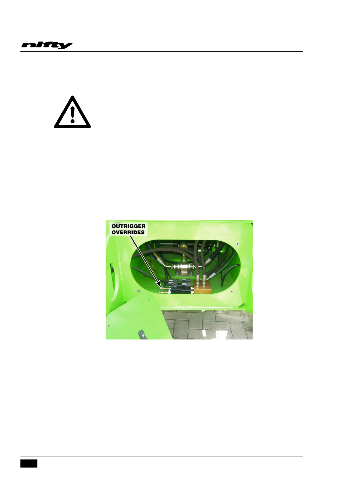
5.4.5 MANUAL OUTRIGGER RECOVERY
IMPORTANT: ALWAYS STOW ALL OF THE BOOMS BEFORE USING THIS
FUNCTION. FAILURE TO DO THIS CAN RESULT IN SERIOUS INJURY OR
DEATH!
Note; Two persons are required for this procedure. To manually recover the outriggers in the event
of loss of power, ensure the Diverter Valve handle is turned towards the operator (see Section 5.3.2)
and both the CT17 Tap (red) and CT20 Tap (gold) are fully closed. Next either push the outrigger
override fully in and hold, or pull fully out and hold. Now use the Booms Hand Pump to operate the
outrigger function. The push or pull function of the Outrigger Overrides determine whether the
outriggers are deployed or retracted. The two Outrigger Overrides operate either the left or right
outrigger and are located in both ends of the chassis by removing the end covers. Return the diverter
valve handle to booms position (facing right) to allow canopy to close. This ensures that the hand
pump always defaults to ‘booms’ position when needed’.
5.5 INCIDENT NOTIFICATION
It is a mandatory requirement that any accident or incident involving a Niftylift is reported by telephone
directly to Niftylift, regardless of whether any party received injury or property was damaged. Failure to
do so may render any warranty on the machine void.
USA – 04/16
Issue 04
Page 45

43
6 Responsibilities
6.1 CHANGES IN OWNERSHIP
When a change of ownership of a Niftylift occurs, it shall be the responsibility of the seller to notify
Niftylift direct of the unit, model and serial number and the name and address of the new owner within
60 days. This important step is required so that all future Technical Bulletins are able to reach the
registered owner of each Niftylift without delay. Please note warranties are not transferable.
6.2 MANUAL OF RESPONSIBILITIES
You are required by ANSI/SIA 92.5 2006, to read and understand your responsibilities before you use
or operate this aerial basket.
Please read the enclosed document, as failure to do so could result in death or serious injury.
Wherever any contradiction may appear, the Manual of Responsibilities shall take precedence over all
other documents.
SD64 Series
Operating & Safety Instructions
USA – 04/16
Issue 04
Page 46
SD64 Series
44
TOWING
PASS
FAIL
N/A
Check brakes are released or…
Check wheel gearboxes disengaged
OUTRIGGERS
Micro-switches secure
Operation of each micro-switch and klaxon
Operation of outrigger control valve and buttons
Operation of each hydraulic outrigger
Operation of boom rest micro-switch
AXLES, WHEELS AND BRAKES
Axles are secure
Wheels are secure, tire condition acceptable
Axle holding bolts secure
Tire pressure correct
Wheel nut torque correct
BASE
Operation of Emergency Stop button
Operation of base control valve and buttons
Operation of all booms over full range
Cylinders are silent
Basket is level over full range
Booms, levelling rods not damaged or distorted
Booms, levelling, cylinders not fouling
Hoses not tight, kinked or fouled
Operation of emergency hand pump
BOOM ROTATION
Boon rotation assembly and motor are secure
Worm/wheel mesh correct, no excessive wear
No end float of worm in housing
Boom rotation gear wheel bolts secured
Boom rotation gear guards secure
Operating & Safety Instructions
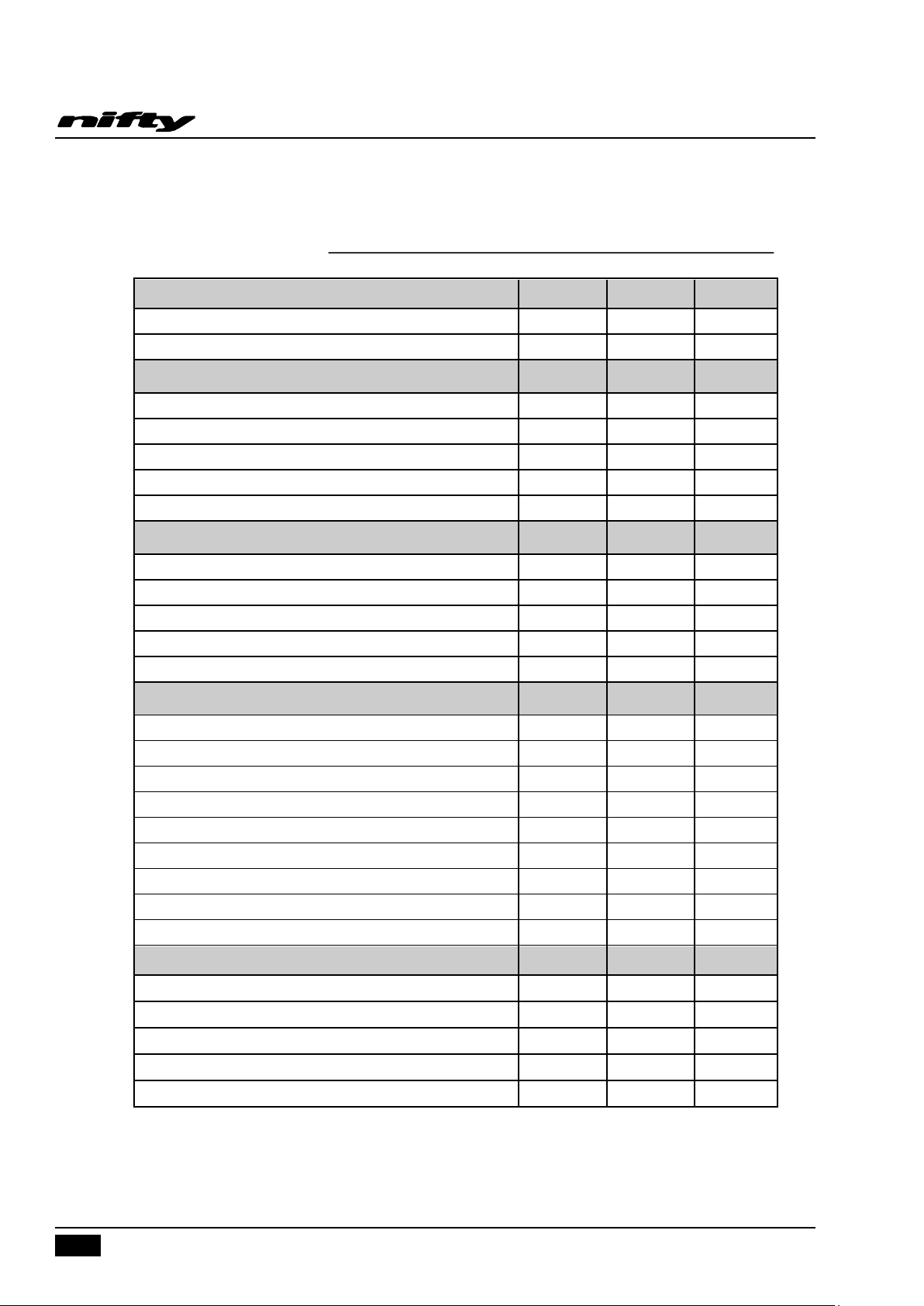
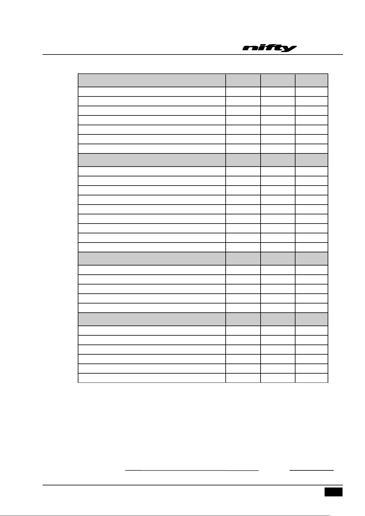
6.3 INSPECTION/SERVICE/PRE-HIRE CHECK LIST
MACHINE SERIAL NO
USA – 04/16
Issue 04
Page 47
SD64 Series
45
BASKET
PASS
FAIL
N/A
Operation of Emergency Stop button
Operation of control valve and buttons
Operation of SiOPS
Operation of all booms over full range
Cylinders are silent
Basket levelling over full range
Boom rotation smooth over full range
INTERNAL (POWER PACK)
Power pack and all components secure
All cables and terminals secure
All hose connections secure
Hoses not kinked or fouled
Charger/control box secure
Battery secure
Electrolyte level and specific gravity
Charger operation
Hydraulic oil level
FINISH
Serial plate against documentation
Swing bolts
Correct decals, all visible
Canopy/bonnets
Grease nipples (Tow coupling, Boom rotation gear ring)
LEAK CHECK
Cylinders (Lift, Outriggers, Telescope, Levelling)
Control valves
Check valves
Power pack/pump
Boom rotation motor
Hose connections
Operating & Safety Instructions
Comments, remedial work required etc;
INSPECTED BY: DATE: / /
USA – 04/16
Issue 04
Page 48

 Loading...