


AUTOMATIC
FOOD SERVICE
EQUIPMENT
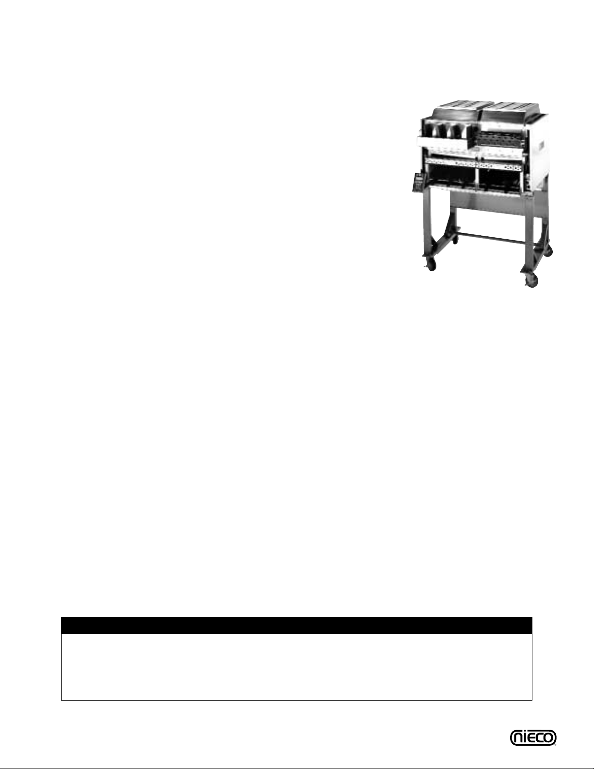
AUTOMATIC GAS BROILER
MODEL 8025
OWNERS MANUAL
IMPORTANT: RETAIN THIS MANUAL IN A SAFE PLACE
FOR FUTURE REFERENCE.
Broiler area must be kept free of combustible materials, and the flow of combustion and ventilation air
must not be obstructed. Operating personnel must not perform any maintenance or repair functions.
Contact your Nieco Authorized Dealer.
In a prominent location, post instructions to be followed in the event the user smells gas.This information shall be obtained by consulting your local gas supplier.
FOR Y OUR SAFETY:
Do not store or use gasoline or other flammable vapors or liquids in
the vicinity of this or any other appliance.
WARNING: Improper installation, adjustment, alteration, maintenance
can cause property damage, injury, or death. Read the installation,
operating and maintenance instructions thoroughly before installing
or servicing this equipment.
DRAFT
REV. 2
4/16/02

2
TABLE OF CONTENTS
A. General Information . . . . . . . . . . . . . . . . . . . . . . . . . . . . . . . . . . . . . . . . .3
A.1 Description . . . . . . . . . . . . . . . . . . . . . . . . . . . . . . . . . . . . . . . . . . .3
A.2 Warranty Information . . . . . . . . . . . . . . . . . . . . . . . . . . . . . . . . . . .3
A.3 Service/Technical Assistance . . . . . . . . . . . . . . . . . . . . . . . . . . . . .4
A.4 Safety Information . . . . . . . . . . . . . . . . . . . . . . . . . . . . . . . . . . . . .4
B. Machine Installation . . . . . . . . . . . . . . . . . . . . . . . . . . . . . . . . . . . . . . . . .6
B.1 Pre-Installation . . . . . . . . . . . . . . . . . . . . . . . . . . . . . . . . . . . . . . . .6
B.2 Mounting . . . . . . . . . . . . . . . . . . . . . . . . . . . . . . . . . . . . . . . . . . . .6
B.3 Leveling . . . . . . . . . . . . . . . . . . . . . . . . . . . . . . . . . . . . . . . . . . . . .6
B.4 Hood Requirements . . . . . . . . . . . . . . . . . . . . . . . . . . . . . . . . . . . .7
B.5 Clearance . . . . . . . . . . . . . . . . . . . . . . . . . . . . . . . . . . . . . . . . . . .7
B.6 Gas Connection . . . . . . . . . . . . . . . . . . . . . . . . . . . . . . . . . . . . . . .8
B.7 Flexible Gas Line Installation . . . . . . . . . . . . . . . . . . . . . . . . . . . . .8
B.8 Restraining Device . . . . . . . . . . . . . . . . . . . . . . . . . . . . . . . . . . . . .9
B.9 Electrical Connection . . . . . . . . . . . . . . . . . . . . . . . . . . . . . . . . . . .9
B.10Pre-Operation Check . . . . . . . . . . . . . . . . . . . . . . . . . . . . . . . . . . .9
C. Troubleshooting Guide . . . . . . . . . . . . . . . . . . . . . . . . . . . . . . . . . . . . . .35
D. Operation . . . . . . . . . . . . . . . . . . . . . . . . . . . . . . . . . . . . . . . . . . . . . . . . .13
D.1 Controls and Indicators . . . . . . . . . . . . . . . . . . . . . . . . . . . . . . . . .13
D.2 Step-by-Step Lighting Procedure . . . . . . . . . . . . . . . . . . . . . . . . .15
D.3 Shutdown Procedure . . . . . . . . . . . . . . . . . . . . . . . . . . . . . . . . . .17
D.4 Control Operation . . . . . . . . . . . . . . . . . . . . . . . . . . . . . . . . . . . . .18
E. Assembly/Disassembly and Cleaning . . . . . . . . . . . . . . . . . . . . . . . . . .21
F. Broil Chain Tension & Link Removal . . . . . . . . . . . . . . . . . . . . . . . . . . .38
G. Parts and Locations . . . . . . . . . . . . . . . . . . . . . . . . . . . . . . . . . . . . . . . .39
G.1 Main Chamber Removable Parts . . . . . . . . . . . . . . . . . . . . . . . . .39
G.2 Flex Chamber Removable Parts . . . . . . . . . . . . . . . . . . . . . . . . . .40
G.3 Feed End View Components . . . . . . . . . . . . . . . . . . . . . . . . . . . . .41
G.4 Main Chamber Side View Components . . . . . . . . . . . . . . . . . . . . .42
G.5 Flex Chamber Side View Components . . . . . . . . . . . . . . . . . . . . .43
G.6 Model 8025 Parts List . . . . . . . . . . . . . . . . . . . . . . . . . . . . . . . . . .44
H. Wiring Diagram . . . . . . . . . . . . . . . . . . . . . . . . . . . . . . . . . . . . . . . . . . . .45
I. Specifications . . . . . . . . . . . . . . . . . . . . . . . . . . . . . . . . . . . . . . . . . . . . .46
J. Warranty Information . . . . . . . . . . . . . . . . . . . . . . . . . . . . . . . . . . . . . . .48
Nieco Corporation - Model 8025
3
A. GENERAL INFORMATION
A.1 Description
The Nieco®Model 8025 automatic broiler, utilizes dual broil chambers, high
release convection burners, electric elements, a new, simplified ignition system,
easy cleaning and a state-of-the-art computer control to help eliminate broiling
problems and provide the operator with even greater control over the broiling
environment.The 8025 is return-flow, with an automatic product return system,
allowing for space savings, while delivering product to the feed end of the broiler.The 8025 is also equipped with a heated product holding unit which allows
for limited product holding.
This manual provides the safety, installation and operating procedures for the
Nieco Automatic Broiler Model 8025.We recommend that all information contained in this manual be read prior to installing and operating the broiler.
A.2 Warranty Information
Please read the full text of the limited Warranty in this manual.
If the unit arrives damaged, contact the carrier immediately and file a damage claim with them. Save all
packing materials when filing a claim. Freight damage claims are the responsibility of the purchaser and
ARE NOT covered under warranty.
The warranty does not extend to:
• Damages caused in shipment or damage as a result of improper use.
• Installation of electrical service.
• Normal maintenance as outlined in this manual.
• Malfunction resulting from improper maintenance not in accordance with the steps contained in
this manual and any applicable training.
• Damage caused by abuse or careless handling outside of the normal operating procedures
contained in this manual.
• Damage from moisture into electrical components.
• Damage from tampering with or removal of any safety device.
IMPORTANT!
Keep these instructions for future reference. If the unit changes ownership,
be sure this manual accompanies the equipment.
IMPORTANT
The Nieco Corporation reserves the right to change specifications and product design without
notice. Such revisions do not entitle the buyer to corresponding changes, improvements,
additions or replacements for previously purchased equipment.
Nieco Corporation - Model 8025
4
A.3 Service/Technical Assistance
If you experience any problems with the installation or operation of your broiler, contact your local
Authorized Nieco Distributor.
Fill in the information bellow and have it handy when calling your authorized service agency for assistance.
The serial number is on the broiler rating plate on the side of the unit.
Purchased from:
Date of Purchase:
Model No.:
Serial No.:
For the name of your local Authorized Nieco Distributor, please call (800) 821-2141.
Use only genuine Nieco replacement parts in your broiler.Use of replacement parts other than those sup-
plied by Authorized Nieco Distributors and Service Agencies will void the warranty and may significantly
alter the performance of your broiler. Your local Authorized Nieco Distributor and Service Agent has been
factory trained and has a complete supply of parts for your Nieco Automatic Broiler.
You may contact the factory direct at (707) 284-7100 if you have trouble locating your local Nieco
Distributor.
A.4 Important Safety Information
Throughout this manual, you will find the following safety words and symbols that signify important safety
issues with regards to operating or maintaining the equipment:
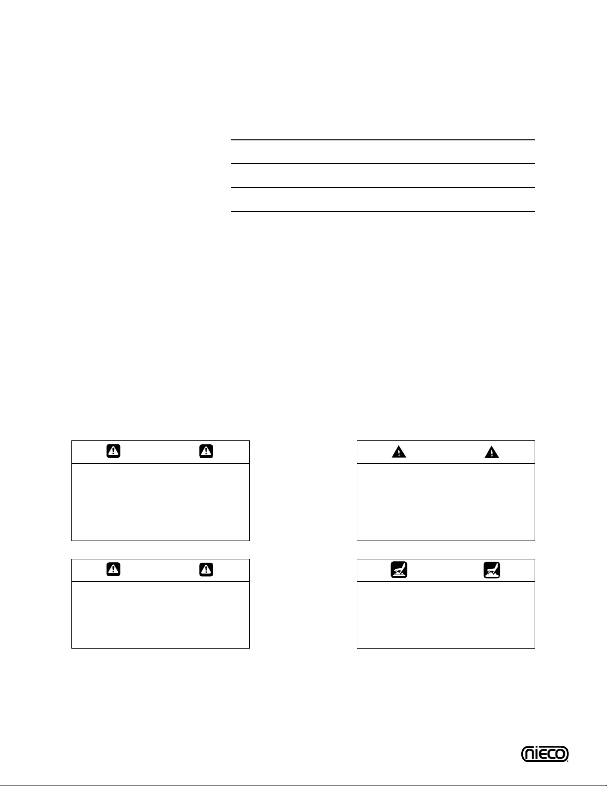
WARNING
GENERAL WARNING. Indicates
information important to the proper
operation of the equipment. Failure
to observe may result in damage to
the equipment and/or severe bodily
injury or death.
WARNING
ELECTRICAL WARNING. Indicates
information relating to possible
shock hazard. Failure to observe
may result in damage to the equipment and/or severe bodily injury or
death.
CA UTION
GENERAL CAUTION. Indicates
information important to the proper
operation of the equipment. Failure
to observe may result in damage to
the equipment.
WARNING
HOT SURFACE WARNING. Indicates
information important to the handling of equipment and parts.
Failure to observe caution could
result in personal injury.
Nieco Corporation - Model 8025

5
A.4 Important Safety Information (Cont.)
In addition to the warnings and cautions in this manual, use the following guidelines for safe operation of
your Nieco Automatic Broiler:
• Read and follow all instructions before using this equipment.
• Install or locate broiler only for its intended use as described in this manual.
• Do not operate this equipment if it has a damaged cord or plug, if it is not working properly or if it
has been otherwise damaged.
• This equipment should only be serviced by authorized personnel. Contact your local Nieco
Distributor for adjustment or repair.
• Use only genuine Nieco replacement parts for your broiler. Failure to do so will void the warranty
and may significantly alter the performance of your broiler.
The following warnings and cautions appear throughout the manual and should be carefully
observed:
• Turn the broiler off, close the main gas valve, and disconnect the plug before
performing any service, maintenance or cleaning on the broiler.
• Always allow the broiler to fully cool before performing any service, maintenance or
cleaning. Failure to wait for the broiler to cool fully may result in personal injury.
• The procedures in this manual may include reference to the use of chemical products.The
Nieco Corporation does not endorse the use of any particular cleaning/degreasing agent.
Use only those chemicals that are approved for use in your kitchen.
• The broiler should be grounded according to local electrical codes to prevent the
possibility of electrical shock. It requires a grounded receptacle with separate electrical
lines, protected by fuses or circuit breakers of the proper rating.
• All electrical connections must be in accordance with local electrical codes and any other
applicable codes.
• The use of adequate ventilation (as rated in this manual) with this broiler is mandatory.
Failure to adequately ventilate this unit and provide safe operating distances (as specified
in this manual) is a fire safety hazard. Follow the instructions for emergency broiler
shutdown in the event of an emergency.
• No attempt should be made to operate this appliance in the event of a power failure.
WARNING ELECTRICAL SHOCK HAZARD. FAILURE TO FOLLOW THESE INSTRUCTIONS COULD
RESULT IN SERIOUS INJURY OR DEATH:
_
Electrical ground is required on this appliance.
_
Check with a qualified electrician if you are in doubt as to whether the appliance is properly
grounded.
_
Do not use water on or near the control box located on the underside of the broiler for risk
of serious injury or death due to electrical shock.
WARNING,HIGH TEMPERATURES WITH HOT SURFACES. FAILURE TO FOLLOW THESE PROCEDURES COULD RESULT IN SERIOUS INJURY:
_
Do not attempt to clean, disassemble or perform maintenance on this broiler until it is fully
cooled as per the instructions contained in this manual.
Nieco Corporation - Model 8025
6
Nieco Corporation - Model 8025
B. INSTALLATION
B.1 Pre-Installation
Uncrate the broiler and inspect for shipping damage. Remove the tape securing the machine par ts, and
install the parts in their proper location. Refer to the Parts and Location section of this manual. If there
are obvious or concealed damages to any part of the broiler, please contact your freight carrier.The factory warranty does not cover freight damage.
B.2 Mounting
Follow the mounting instructions if this function is not performed by the installer.
B.3 Leveling
The grease drain system is based on a gravity-flow design. Therefore, it is extremely important to level
the broiler during installation. Use levelling shims (P/N 11936).
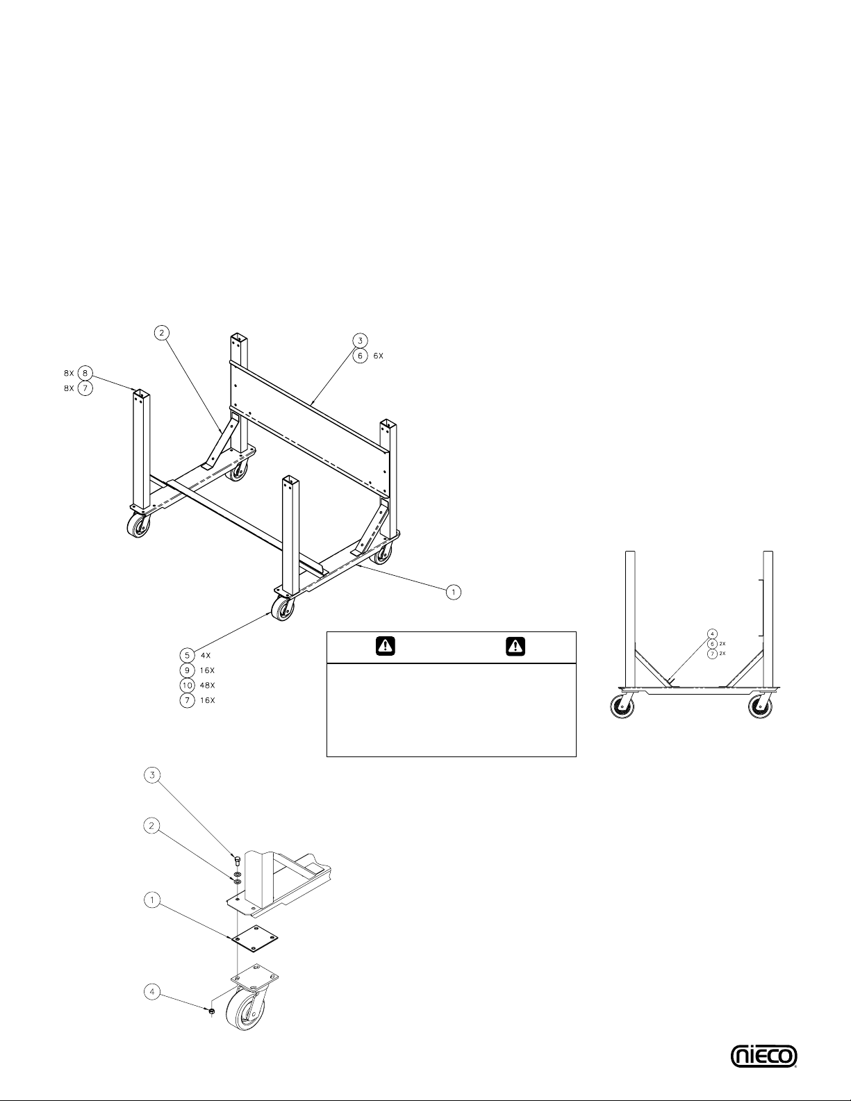
ITEM P/N QTY DESCRIPTION
1 11939 1 Left Stand Leg Assembly
2 11940 1 Right Stand Leg Assembly
3 10803 1 Shear Plate
4 10410 1 Freezer Stop
5 95099 4 Caster
6 11881 1 Control Pad Bracket
7 11089 1 Quick Release Pin
8 10476 8 3/8X7/8” Bolt
9 11888 16 3/8X1 1/4” Bolt
10 10475 8 3/8X2” Bolt
11 10477 16 3/8” Lock Nut
12 5599 32 3/8” Washer
CA UTION
Prior to mating stand to broiler, and
with stand in operating location, verify
that stand is level within 1/8”. If not,
shim as required.
SHIM INSTALLATION:
1. Prior to mating stand to broiler and with stand in operating position, verify
that stand is level within an 1/8”inch.
2. If shimming is required, determine which caster(s) should be shimmed.
3. Elevate side of stand to be shimmed off of floor.
4. Remove caster(s) to be shimmed.
5. When installing shims, remove existing hardware, discard washers (ITEM 2),
and reuse nuts and bolts.
6. After adding shim(s) and securing caster(s), lower broiler.
7. Check to verify that broiler is now level.
ITEM P/N QTY DESCRIPTION
1 11936 AR Stand Shim
2 5599 REF 3/8” Washer
3 11888 REF 3/8X1 1/4” Bolt
4 10477 REF 3/8” Locknut
7
Nieco Corporation - Model 8025
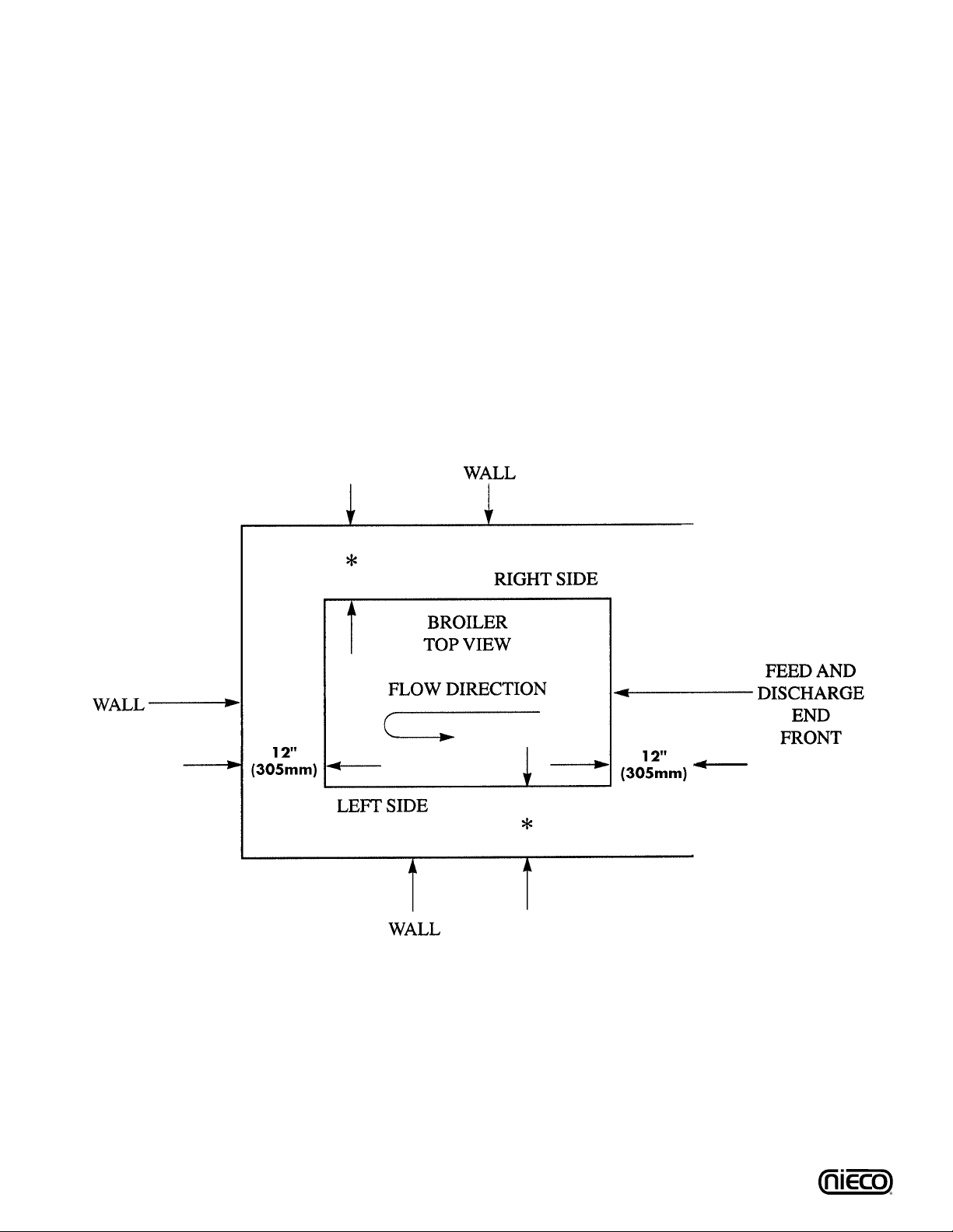
*
12” (305mm) Minimum, preferably 610 mm (24”) or more for service. Location clearances are from walls of broiler height.
B.4 Hood Requirements
This appliance must be installed under a ventilation hood of adequate size and the following minimum
capacity:
Model SCFM
8025 1050
Do not obstruct the flow of combustion and ventilation air. An adequate air supply must be available for
safe and proper operation.
B.5 Clearance
For proper installation the minimum clearance from combustible and non-combustible construction must
be 305 mm (12”) from the back and 305 mm (12”) from the front of the machine.Keep appliance area
free from combustibles.
To facilitate disassembly and service of the unit a minimum of 610 mm (24”) should be allowed on the
control panel (feed end) of the broiler, as well as in front and back of the broiler.
8
B.6 Gas Connection- 1” N.P.T. (Nieco P/N 11966; 1” Flexible Gas Line)
At rated input the gas supply should deliver a minimum pressure of at least 15 mbar (5" water column) at the broiler
connection for natural gas.Incoming gas supply pressure must not exceed 50 mbar (14" water column).
Note: The installation of this appliance must conform with local codes, or in the absence of local codes, with the
National Fuel Gas Code, ANSI Z223.1, Natural Gas Installation Code, CAN/CGA-B149.1 including:
1. The appliance and its individual shutoff valve must be disconnected from the gas supply
piping system during any pressure testing of that system at test pressures in excess of
1/2 psi (3.45 kPa).
2. The appliance must be isolated from the gas supply piping system by closing its
individual manual shutoff valve during any pressure testing of the gas supply piping
system at test pressures equal to or less than 1/2 psi (3.45 kPa).
By public initiative, the State of California has adopted legislation (Proposition 65) which requires manufacturers of many types of products, including gas appliances, to warn consumers of their products that contain chemicals or produce substances listed by the State of California to either cause cancer, birth defects
or other reproductive harm.
Nieco Corporation - Model 8025
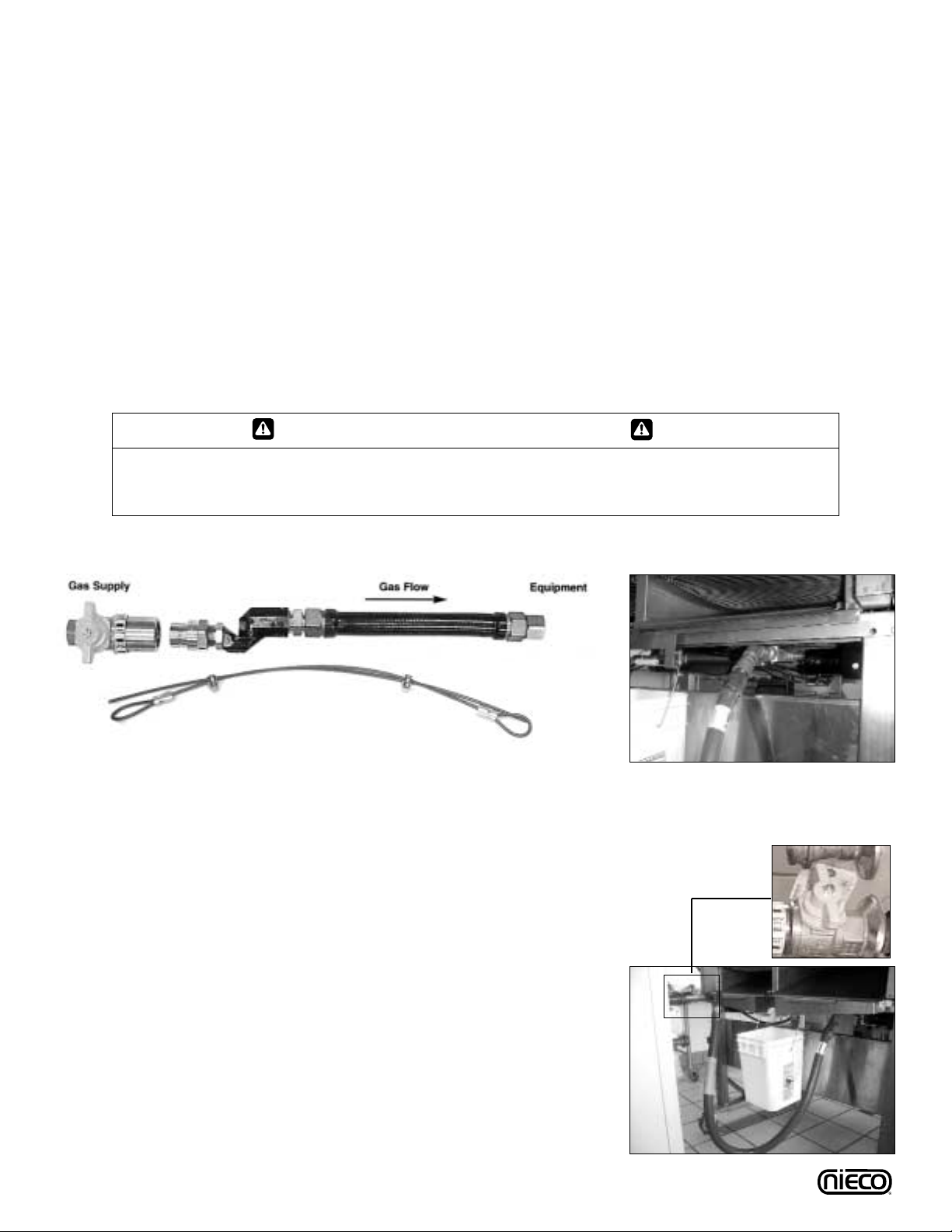
For safety in the kitchen area, and to insure maximum
service life, it is vitally important to correctly install connectors. The connector shall comply with the Standard for
Connectors for Moveable Gas Appliances, ANSI Z21.69 or
CAN/CGA-6.16 and a quick disconnect device that complies with the Standard for Quick-Disconnect Devices for
use with gas fuel, ANSI Z21.41 or CAN1-6.9
In order to avoid sharp kinks or excessiv e bends that could
have a damaging effect on the connector, it may be necessary to attach pipe elbows in order to bring the connector
into its proper plane. For easy movement of the appliance,
the connector should be installed with a "lazy" loop for minimum tension.
Note: Gas appliances should be disconnected prior to
maximum movement. (Minimal movement is possible
to connect hose.)
B.7 Installing Gas Appliance Connectors and Flexible Gas Lines Correctly
WARNING
If not installed, operated and maintained in accordance with the manufacturers instructions, this
product could expose you to substances in fuel or from fuel combustion which can cause cancer,
birth defects or other reproductive harm.
P/N 11966 - 1”Flexible Gas Line with Strain Relief Cable
8025 Equipment Side Gas
Connection
8025 Manual
Gas Valve
Correct Gas Line
Installation
9
Nieco Corporation - Model 8025
B.9 Electrical Connection
Power requirements are stated on the unit nameplate and must be connected accordingly.This appliance, when installed must be electrically grounded in accordance with local codes, or in the absence of
local codes, with the National Electrical Code, ANSI/NFPA 70, or the Canadian Electr ical Code, CSA
C22.2, as applicable.Before star ting broiler, tighten all electrical connections in control box. An electrical
wiring diagram can be found inside the control box.
Note: Disconnect power before servicing.
B.10 Pre-Operation Check
Be sure that all parts are installed in the proper location:
❏ Ventilation is turned on
❏ Broiler is plugged in
❏ Gas line is connected
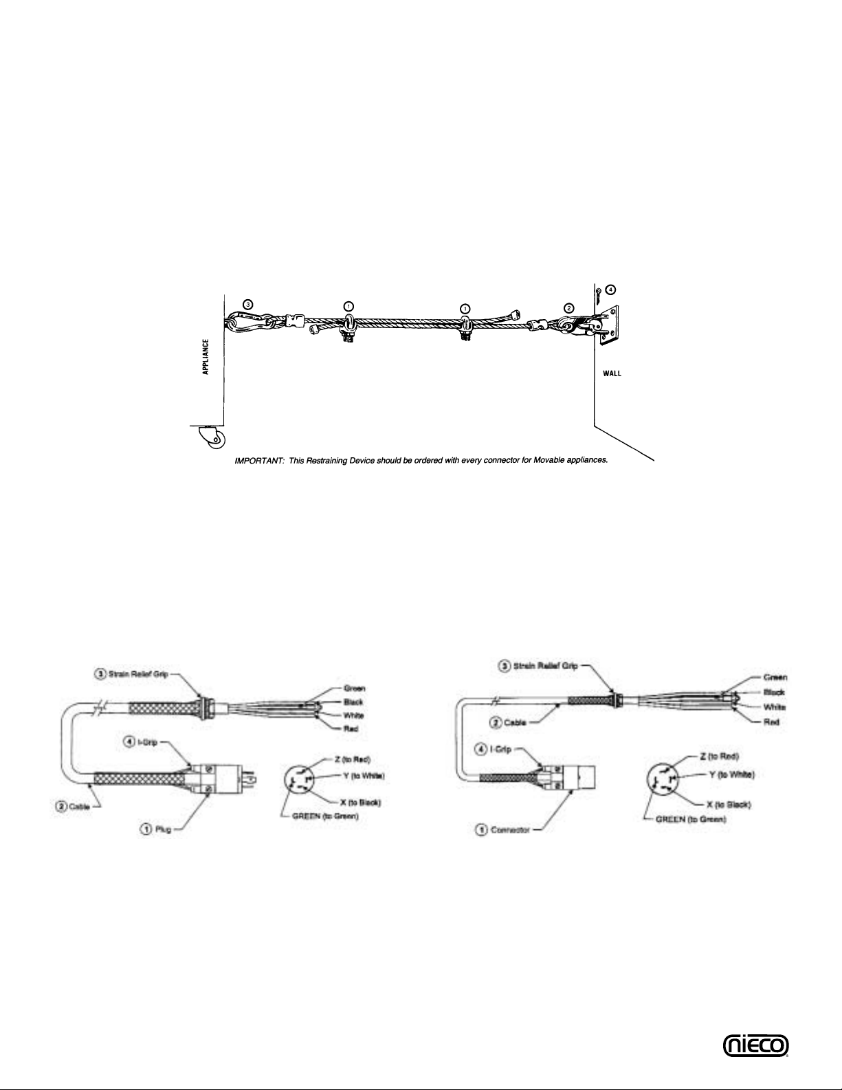
B.8 Restraining Device Installation and Use
This high strength restrainer is to be used with all moveable (castered) appliances. It fully complies with American
Gas Association requirements. References: Z21.69, Z83.11, and Z21.41 with current revisions. Installation is quick
and positive.In Canada, device is in accordance with CAN 1-6.9-M70 Quick Disconnect Devices for use with gas
fuel, and CAN 1-6.10-88 metal connectors for gas appliances.
Correct length for any appliance is simply a matter of loosening two adjuster clips (1) and re-tightening.(3" to 6"
shorter than appliance connector is desired length.)
Restrainer is made of heavy duty steel cable, with a strong scissor hood (2) at one end, and an equally strong
spring hook (3) at the other.Cotter pin (4) is supplied to secure the installation. For proper attachment to the broiler,
use the supplied hardware to attach the device to the holes in the shear plate of the broiler stand.
NOTE: If disconnection of the restraint is necessary, reconnect the restraint after the appliance has been
returned to its originally installed position.
P/N 11961 - 3ft Female Power Cord
30A 250V 3-Pole 4-Wire Grounding - NEMA L15-30P
P/N 11960 - 6ft Male Power Cord
30A 3Ø 250V 3-Pole 4-Wire Grounding NEMA L15-30P

C.TROUBLESHOOTING
Problem Solution
Pilots not lighting ❏ Check that broiler is plugged in, gas valve is
open and broiler is turned on
❏ The 5-minute time limit was exceeded -
press the timer reset button
❏ Manually light if it is not a timer problem
❏ Check for ignition
❏ Check for clogged pilot
Burners not
lighting
❏ Check for gas pressure, if there is pressure,
use the manual lighting procedure
❏ If no gas pressure, call for service
❏ Check for proper burner installation
❏ Check for plugged burner orifices
❏ Check for plugged pilot burner
Pilot not staying lit
❏ Hold in red pilot button longer
❏ Call for service as red pilot button or
thermocouple may need replacing
Broil chain jams
❏ Procedure to correct:
__ Push reset button on keypad once to
reverse chain
__ Push reset button a second time to run
chain forward
If chain jams again, check:
__ Arrestors for proper placement (Make
sure flex chamber arrestors are under
both chains)
__ For sag in the chain with arrestors in
place (Chain may need a link removed)
__ For an obstruction
Return chains not
moving
❏ Verify that return chains have correct side up
with drive shaft coupling lined up with
engagement pin
❏ Check for sag in the return chain (May need
to have a link removed)
10
Always verify that the broiler is properly assembled, the hood is on, gas valve open and broiler is plugged in.
Nieco Corporation - Model 8025

11
Return chain jams ❏ Remove any obstruction if needed
❏ Press the black reset button located on the
left (MAIN CHAMBER) side of the broiler
control box (underneath).
❏ Check the motor drive chain (bicycle chain)
for any obstructions or jams
Product not cooking to
proper temperature in
cookouts
❏ Adjust cook time
❏ Check that broiler is calibrated properly
❏ Check that all burners are lit
❏ Check that all parts are installed correctly,
and that lower burner holes are facing up
❏ Check that broiler is properly cleaned
and assembled
❏ Check ventilation
__ Make sure there isn’t excessive
exhaust or an air vent blowing on the
broiler
Problem Solution
Nieco Corporation - Model 8025
No display on
computer control
keypad
❏ If there is no text displayed on the keypad
but the backlighting is on, check the
connection at the keypad
❏ Call ser vice if necessar y
Alternative display
shown on computer
control keypad
❏ Depress select button on the keypad to
change view

12
Meat patties not
returning
❏ Check that patties have not gotten stuck on
the return slide
__ Remove awnings to check
__ Remove product from return slide if
necessary
__ Proper cleaning of retur n slide is
needed daily to remove buildup which
can cause patties to stick
❏ Check return chain to see if patties
are stuck in chain
__ Remove product, then check to make
sure the broiler has been assembled
properly (Awnings, return slide and
stripper blades)
Temperature on
display reads “OPEN”
❏ Inspect wire leads coming out of
temperature probe
__ Remove side panel located above
thermocouple
__ If wire is cut or exposed (insulation),
call service
Computer control
freezes or locks up
(screen doesn’t
change when you
press a button
❏ Reset
__ Turn main power switch off
__ Push and hold red pilot button on
main and flex chambers to relight
__ Turn on again; burners should relight
automatically. If not, follow lighting
procedure
Too much smoke/heat
in the kitchen
❏ Check that hood and fan are working
correctly
❏ Check that broiler is properly positioned
under the hood; check all sides of broiler
❏ Check condition of catalyst (after broiler is
turned off and cooled at end of night) clean if
necessary
❏ Check condition and placement of grease
extractors; clean daily and position properly
Grease on floor from
discharge end
❏ Check that grease troughs are facing into
the grease bucket
Problem Solution
Nieco Corporation - Model 8025
13
D. OPERATION
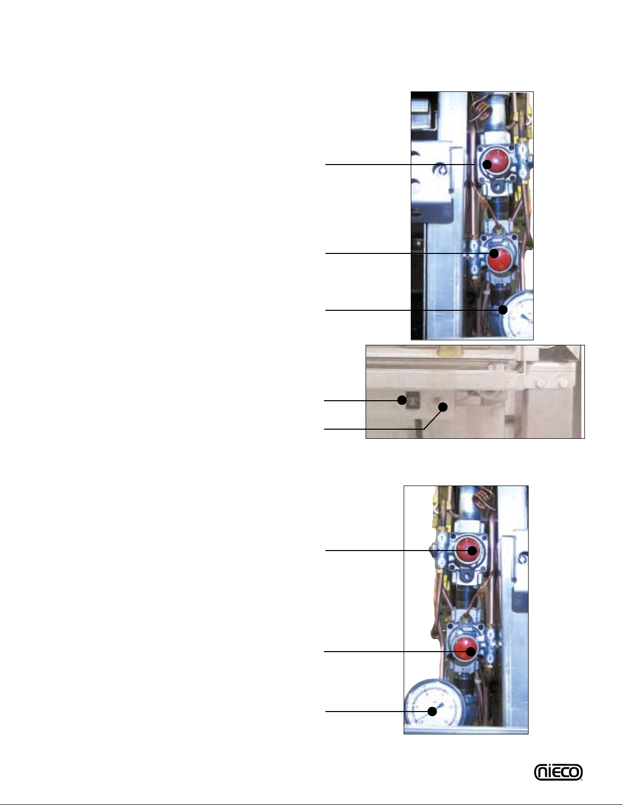
D.1 Controls and Indicators
ON THE FLEX CHAMBER SIDE
Upper Red Pilot Button (P/N 2123)
Lower Red Pilot Button (P/N 2123)
Gas Pressure Gauge (P/N 2001)
ON THE MAIN CHAMBER SIDE
Upper Red Pilot Button (P/N 2123)
Lower Red Pilot Button (P/N 2123)
Gas Pressure Gauge (P/N 2001)
Nieco Corporation - Model 8025
Main On/Off Switch (P/N 10503)
Ignitor Reset Button (P/N 11025)
14
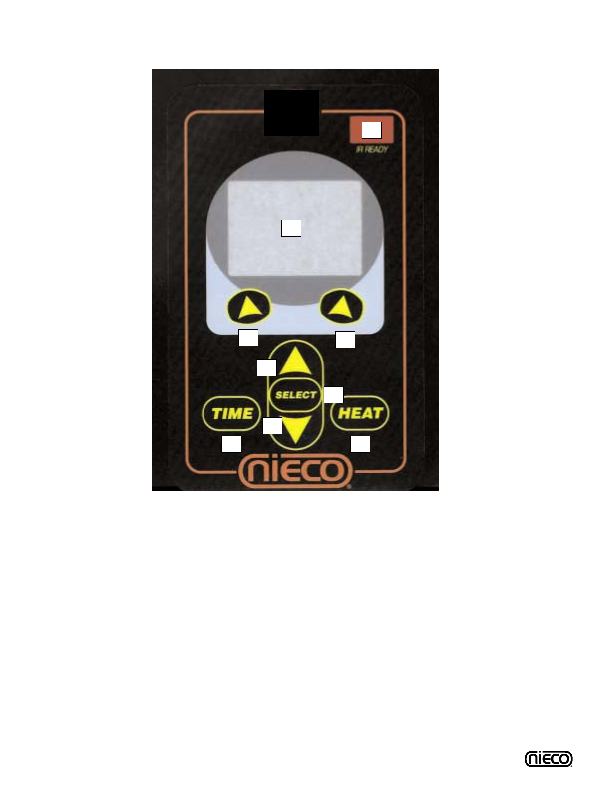
D.1 Controls and Indicators (Cont.)
Nieco Corporation - Model 8025
(1) IR READY - Infra-red port for remote control programming (not currently used).
(2) LED DISPLAY
(3) LEFT MENU SELECTION BUTTON
(4) RIGHT MENU SELECTION ARROW
(5) UP PRODUCT SELECTION BUTTON - Press to change active product selected.
(6) DOWN PRODUCT SELECTION BUTTON- Press to change active product selected.
(7) SELECT BUTTON - Press to enter selection.
(8) HEAT BUTTON - Press to change top heat settings for Flex chamber (belt 2) ONLY.
(9) TIME BUTTON - Press to change cook time of active chain.
(1)
(2)
(4)
(9) (8)
(5)
(6)
(7)
(3)
15
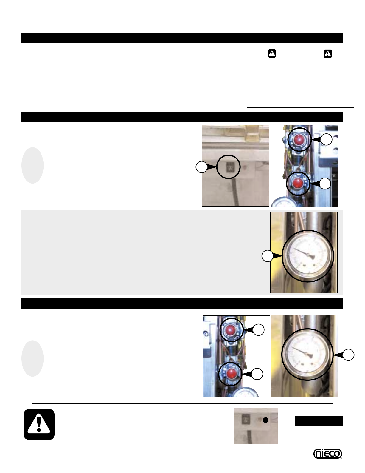
D.2 Lighting Procedures
1. Broiler is
centered under
hood and
plugged in
2. Gas valve is
open when
handle is in line
(parallel to) the
pipe
3. Turn ventilation
system on
PILOTS MUST BE LIT WITHIN 5 MINUTES; IF YOU EXCEED 5
MINUTES, PRESS THE RESET BUTTON NEXT TO THE ON/OFF
SWITCH AND REPEAT IGNITION PROCEDURES. IF REIGNITION FAILS, COMPLETELY SHUT OFF THE BROILER,WAIT 5
MINUTES AND REPEAT THE IGNITION PROCEDURES.
Reset Button
1
Turn the MAIN POWER SWITCH (a) on. Starting
with the MAIN CHAMBER RED PILOT BUTTONS,
push and hold the
LOWER BUTTON FIRST (b) for
30 seconds after the pilot has lit. Then press the
UPPER PILOT BUTTON (c) for 30 seconds after
the pilot has lit.
2
After releasing red pilot buttons; check GAS PRES-
SURE GAUGE (a)
reading. Gauge should read 4”.If
not, follow troubleshooting tips in section E of this
manual.Verify that main chamber burners - upper
and lower - have lit.
NOTE: GAS PRESSURES ARE
YET TO BE DETERMINED.
3
Move to the FLEX CHAMBER RED PILOT
BUTTONS, push and hold the LOWER RED PILOT
BUTTON (a)
for 30 seconds after the pilot has lit.
Release, and verify that the burners have lit.The
press and hold the UPPER RED PILOT BUTTON
(b)
for 30 seconds after the pilot has lit. Release,
and verify that the burners have lit. Verify that the
GAS PRESSURE GAUGE (c) reads 4”. NOTE:
GAS PRESSURES ARE YET TO BE DETERMINED.
a
WARNING
THE VENTILATION SYSTEM MUST
BE ON AT ALL TIMES DURING
BROILER OPERATION. OPERATING
BROILER WITHOUT PROPER
VENTILATION IS A SEVERE FIRE
HAZARD.
MAIN CHAMBER IGNITION
b
c
PRE-LIGHTING PREPARATION
FLEX CHAMBER IGNITION
a
c
Nieco Corporation - Model 8025
a
b
 Loading...