

Nieco 650G Installation Manual

B UILT-IN R EFRIGERATION
INSTALLATION INSTRUCTIONS
CONTENTS
Installation Recommendations 3
Installation Specifications 4
nstallation Instructions 8
I
Framed Panel Installation 12
Overlay Panel Installation 16
Completing the Installation 20
Service Information 23
Specifications are subject to change without notice.
Check our website, subzero.com, for the most
up-to-date specifications.
As you follow these instructions, you will
notice WARNING and CAUTION symbols.
This blocked information is important for the
safe and efficient installation of Sub-Zero
equipment. Ther
hazards that may occur during installation.
e are two types of potential
SUB-ZERO®is a registered trademark of Sub-Zero Freezer Company, Inc.
signals a situation where minor injury or
oduct damage may occur if you do not
pr
follow instructions.
states a hazard that may cause serious
y or death if pr
injur
followed.
Another footnote we would like to identify is
ANT NOTE: This highlights infor
T
IMPOR
tion that is especially r
ee installation.
fr
ecautions ar
elevant to a pr
e not
ma
oblem-
-

BUILT-IN INSTALLATION RECOMMENDATIONS
INSTALLATION
RECOMMENDATIONS
The importance of the installation of the
Sub-Zero Built-In unit cannot be overempha-
ized. Installation should be done by a
s
qualified installer.
Before you begin the installation process, it
is recommended that you read this entire
nstallation Instructions book. There are key
I
details that you should take special care to
observe during the installation. By reading
these instructions carefully, you will make the
installation process easier, problem-free and,
most importantly, safe.
Any questions or problems about the
installation should be directed to your
Sub-Zero dealer or the Sub-Zero Customer
Service Department at 800-222-7820 or e-mail
customerservice@subzero.com. You can also
visit our website at subzero.com.
TOOLS AND MATERIALS REQUIRED
he following is a list of tools and materials
T
that should be available for proper installation.
Phillips screwdriver set
lotted screwdriver set
S
Torx drive screwdriver set
4' (1.2 m) of
1
/4" copper tubing and saddle
valve for the water line—part #4200880
(do not use self-piercing valves)
Copper tubing cutter
Level—2' (.6 m) and 4' (1.2 m) recom-
mended
Appliance Dolly able to support 700 lbs
(317 kg) and adequate manpower to
handle the weight of the unit
Various sized pliers
Wrench set
Allen wrench set
5
/16" hex bolt nut driver
Crescent wrenches
Cordless drill and assorted drill bits
1
Masonite, plywood,
/8" pressed fiberboard,
cardboard or other suitable material to
otect finished flooring
pr
Appropriate materials to cover and protect
the home and its furnishings during installation
Dimensions in parentheses are in
millimeters unless otherwise specified.
3

BUILT-IN INSTALLATION SPECIFICATIONS
INSTALLATION
SPECIFICATIONS
Make sure that the actual equipment that was
shipped to you matches the design you are
xpecting to install. The Sub-Zero Built-In line
e
offers the following design alternatives—
framed, overlay and stainless steel models.
Each of these design options has specific
nstallation requirements, which means it is
i
vital that the unit match your planning and
space needs. Before you begin the installation
process, check the exact model number you
need against the model number on the
shipping carton.
If the unit you receive does not match your
requirements, contact your Sub-Zero dealer.
SITE PREPARATION
ake sure that the finished rough opening
M
where the Built-In unit is to be installed is
properly prepared. Refer to the Overall Dimen-
ions and Installation Specifications for your
s
specific model on the following pages. These
specifications are identical for each of the
design alternatives—whether your model is
framed, overlay or stainless steel. Make sure
that the rough opening dimensions, door
swing clearance, electrical service and
plumbing are correct for the model you are
about to install.
If you are installing Built-In units side by side,
a separating filler strip is recommended. Add
the filler strip width to the finished rough
opening dimension. Complete the installation
with the Anchoring Kit (part #4200900), see
page 21.
IMPORTANT NOTE:
To operate properly, the
door must open a minimum of 90˚. Use a
minimum 3" (76) filler in corner installations to
assure a 90˚ door opening. Allow enough clearance in front of the unit for full door swing.
IMPORTANT NOTE:
Make sure the floor under
the unit is level with the surrounding finished
floor.
4

36"
(914)
7
3"
(1854)
3
6"
(914)
7
3"
(
1854)
36"
(914)
24"
(610)
7
3"
(1854)
723/4" (1848)
ROUGH OPENING
HEIGHT TO
FINISHED
FLOORING
723/4" (1848)
MINIMUM HEIGHT
REQUIRED TO
FINISHED
FLOORING
(LEVELERS IN)
24"
(610)
ROUGH
O
PENING
DEPTH
11"
(279)
3"
(76)
24"
(610)
W
LOCATE WATER SUPPLY
WITHIN BOTTOM SHADED
AREA ONLY (601F ONLY )
LOCATE ELECTRICAL
WITHIN ENTIRE SHADED AREA
6"
(152)
E
SHUT-OFF
VALVE
EXTEND
WATER LINE
APPROX 36" (914)
FROM BACK WALL
(
601F ONLY )
351/2" (902)
ROUGH OPENING WIDTH
FRONT VIEW
TOP VIEW
361/16"
(916)
237/8"
(606)
BEHIND
FRAME
3
/8"(10)
FRAME
EXTENSION
90˚
BUILT-IN INSTALLATION SPECIFICATIONS
OVERALL DIMENSIONS
All Refrigerator | All Freezer Models
Model 601R
A
ll Refrigerator
Width 36" (914)
Height 73" (1854)
Depth 24" (610)
Model 601RG
A
ll Refrigerator
with Glass Door
Width 36" (914)
Height 73" (1854)
Depth 24" (610)
Model 601F
A
ll Freezer
Width 36" (914)
Height 73" (1854)
Depth 24" (610)
LL REFRIGERATOR
A
ALL FREEZER
M
odel 601R
A
ll Refrigerator
M
odel 601RG
A
ll Refrigerator
w
ith Glass Door
Model 601F
All Freezer
Illustrations shown in stainless steel design.
INSTALLATION SPECIFICATIONS
All Refrigerator | All Freezer Models
Models 601R and 601RG will not require the
water line connection.
Dimensions are for finished rough openings.
Door swing clearances are based on
stainless steel door and handle dimensions.
Dimensions in parentheses are in
millimeters unless otherwise specified.
5

30"
(762)
84"
(2134)
36"
(914)
84"
(2134)
30"
(762)
84"
(2134)
36"
(
914)
24"
(
610)
84"
(2134)
833/4" (2127)
ROUGH OPENING
HEIGHT TO
FINISHED
FLOORING WITH
STANDARD
11" (279) GRILLE
83" (2108)
MIN HEIGHT
REQUIRED TO
FINISHED
FLOORING
(LEVELERS IN)
751/2"
(1918)
7"
(178)
6"
(152)
A
ROUGH OPENING WIDTH
24"
(610)
R
OUGH
OPENING
DEPTH
E
3"
(76)
18"
(457)
W
LOCATE WATER SUPPLY
WITHIN SHADED AREA
LOCATE ELECTRICAL
WITHIN SHADED AREA
6"
(152)
SHUT-OFF
VALVE
FRONT VIEW
TOP VIEW
EXTEND
WATER LINE
APPROX 36" (914)
FROM BACK WALL
VER-AND-
B
23
7
/8"
(606)
BEHIND
FRAME
3
/8"(10)
FRAME
EXTENSION
90˚
O
UNDER
M
odel 611
Model 611G
w
ith Glass Door
Model 650
Model 650G
w
ith Glass Door
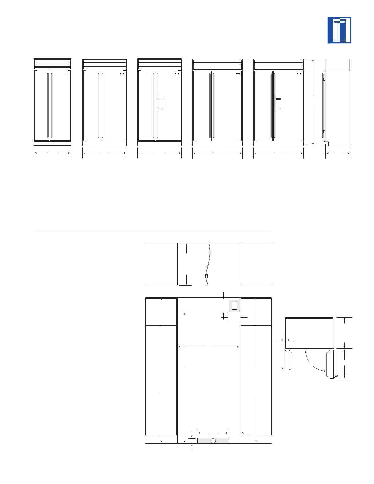
BUILT-IN INSTALLATION SPECIFICATIONS
OVERALL DIMENSIONS
Over-and-Under Models
Model 611
Width 30" (762)
Height 84" (2138)
Depth 24" (610)
Illustra
M
odel 611G
w
ith Glass Door
Width 30" (762)
Height 84" (2138)
Depth 24" (610)
tions shown in stainless steel design.
INSTALLATION SPECIFICATIONS
Over-and-Under Models
Model 611
A) Rough Opening Width 29
Min Door Clearance 301/8" (765)
B)
Model 611G
A)
Rough Opening Width 291/2" (749)
B) Min Door Clearance 30
Model 650
A) Rough Opening Width 35
B) Min Door Clearance 36
Model 650G
A) Rough Opening Width 35
B) Min Door Clearance 36
1
/2" (749)
1
/8" (765)
1
/2" (902)
1
/16" (916)
1
/2" (902)
1
/16" (916)
Model 650
Width 36" (914)
Height 84" (2138)
Depth 24" (610)
M
odel 650G
w
ith Glass Door
Width 36" (914)
Height 84" (2138)
Depth 24" (610)
6
Dimensions are for finished rough openings.
Door swing clearances are based on
stainless steel door and handle dimensions.
36"
(
914)
42"
(
1067)
4
8"
(1219)
42"
(1067)
48"
(
1219)
24"
(
610)
84"
(
2134)
833/4" (2127)
ROUGH OPENING
HEIGHT TO
FINISHED
FLOORING WITH
STANDARD
11" (279) GRILLE
83" (2108)
MIN HEIGHT
REQUIRED TO
FINISHED
FLOORING
(LEVELERS IN)
751/2"
(1918)
7"
(178)
6"
(152)
A
ROUGH OPENING WIDTH
24"
(610)
R
OUGH
OPENING
DEPTH
E
3"
(76)
18"
(457)
W
LOCATE WATER SUPPLY
WITHIN SHADED AREA
LOCATE ELECTRICAL
WITHIN SHADED AREA
6"
(152)
SHUT-OFF
VALVE
FRONT VIEW
TOP VIEW
EXTEND
WATER LINE
APPROX 36" (914)
FROM BACK WALL
B
23
7
/8"
(606)
BEHIND
FRAME
3
/8"(10)
FRAME
EXTENSION
90˚
BUILT-IN INSTALLATION SPECIFICATIONS
OVERALL DIMENSIONS
Side-by-Side Models
Model 661
Width 36" (914)
Height 84" (2138)
Depth 24" (610)
Model 642
Width 42" (1067)
Height 84" (2138)
Depth 24" (610)
INSTALLATION SPECIFICATIONS
Side-by-Side Models
Model 661
A) Rough Opening Width 35
Min Door Clearance 203/4" (527)
B)
Model 642
A)
Rough Opening Width 411/2" (1054)
B) Min Door Clearance 25
Model 685
A) Rough Opening Width 41
B) Min Door Clearance 25
Model 632
A) Rough Opening Width 47
B) Min Door Clearance 29
1
/2" (902)
9
/16" (649)
1
/2" (1054)
9
/16" (649)
1
/2" (1207)
1
/4" (743)
Model 685
I
ce | Water Dispensing
Width 42" (1067)
Height 84" (2138)
Depth 24" (610)
Model 632
Width 48" (1219)
Height 84" (2138)
Depth 24" (610)
Model 695
I
ce | Water Dispensing
Width 48" (1219)
Height 84" (2138)
Depth 24" (610)
Illustra
tions shown in stainless steel design.
SIDE-BY-SIDE
Model 661
Model 642
Model 685
Ice | Water Dispensing
Model 632
Model 695
Ice | Water Dispensing
Model 695
A)
Rough Opening Width 471/2" (1207)
B) Min Door Clearance 29
Dimensions are for finished rough openings.
Door s
stainless steel door and handle dimensions.
Dimensions in parentheses are in
millimeters unless otherwise specified.
1
wing clearances are based on
/4" (743)
7

BUILT-IN INSTALLATION INSTRUCTIONS
ELECTRICAL REQUIREMENTS
A 115 V AC, 60 Hz, 15 amp circuit breaker and
lectrical supply are required. A separate
e
circuit, servicing only this appliance, is
required.
All Sub-Zero Built-In models are equipped with
a power supply cord with a 3-prong grounding
lug, which must be plugged into a mating
p
3-prong grounding-type wall receptacle. Follow
the National Electrical Code and local codes
and ordinances when installing the receptacle.
For location of the electrical supply, refer to the
Installation Specifications illustration for your
specific model on pages 5–7.
IMPORTANT NOTE:
A ground fault circuit
interrupter (GFCI) is not recommended and
may cause interruption of operation.
Do not use an extension cord or twoprong adapter. Electrical ground is
required on this appliance. Do not remove
the power supply cord ground prong.
PLUMBING REQUIREMENTS
For Built-In models with an automatic ice
aker, rough in the water supply line. Connect
m
1
a
/4" OD copper line to the house supply. Use
an easily accessible shut-off valve between the
water supply and the unit. This valve is usually
placed about 6" (152) from the compression
fitting. Do not use self-piercing valves. A
saddle valve kit (part # 4200880) is available
from your Sub-Zero dealer.
The water line should be routed up through
the floor within
1
/2" (13) from the back wall and
no higher than 3" (76) off the floor. If the water
supply is brought in from behind the unit,
route the water line through the back wall, no
more than 3" (76) from the floor. Regardless of
the routing, allow 3' (1 m) of excess copper
tubing to remain outside the wall or floor for
easy connection to the unit. For location of the
water supply, refer to the Installation Specifications illustration for your specific model on
pages 5–7.
A line filter is required when water conditions
have a high sediment content. The ice maker
operates on water pressure of 20 psi (1.4 bar)
to 100 psi (6.9 bar).
The outlet must be checked by a qualified
electrician to be sure that it is wired with
the correct polarity. Verify that the outlet
ovides 115 volts and is properly
pr
grounded.
A reverse osmosis system can be used,
provided there is a consistent water pressure
of 20 psi (1.4 bar) to 100 psi (6.9 bar) supplied
to the water valve at all times.
IMPORTANT NOTE:
In some cases a reverse
osmosis water filter system may not be able to
maintain the minimum water pressure consistently.
Good water is impor
tant for high quality ice.
It is not recommended that the ice maker be
connected to a softened water supply. Water
softener chemicals, such as salt fr
om a
malfunctioning softener, can damage the ice
maker mold and lead to poor ice quality. If a
softened water supply cannot be avoided, it is
important that the water softener be well maintained and operating properly.
Dimensions in parentheses are in
millimeters unless otherwise specified.8
 Loading...