

Nieco 624 Installation Manual
INSTALLATION & OPERATING
INSTRUCTIONS
Raytherm™
Heating
Boilers
Models 133–4001
Type H
WARNING: Improper installation, adjustment, alteration, service or maintenance can
cause property damage, personal injury or loss of life. Refer to this manual.
Installation and service must be performed by a qualified installer, service agency or
the gas supplier.
FOR YOUR SAFETY: Do not store or use gasoline or other flammable vapors and
liquids or other combustible materials in the vicinity of this or any other appliance. To
do so may result in an explosion or fire.
WHAT TO DO IF YOU SMELL GAS:
• Do not try to light any appliance.
• Do not touch any electrical switch; do not use any phone in your building.
• Immediately call your gas supplier from a neighbor's phone. Follow the gas
supplier's instructions.
• If you cannot reach your gas supplier, call the fire department.
Installation and service must be performed by a qualified installer, service agency or
the gas supplier.
This manual should be maintained in legible condition and kept adjacent to the heater or in a safe place for future
reference.
CATALOG NO. 2000.50AG Effective: 09-16-10 Replaces: 01-06-10 P/N 240035 Rev. 34

Rev. 34 reflects the following:
Changes to: Clarification of Note 1 and Note 2 on page 7, Fig. 26 on page 21, Warranty info on page 42
Additions: None
Deletions: None
2

CONTENTS
WARNINGS 4
Pay Attention to These Terms 4
MODEL IDENTIFICATION 5
RECEIVING EQUIPMENT 6
CERTIFICATIONS 6
BOILER TYPES 6
Type H1 - Mechanical Modulating 6
Type H2 - Motorized Modulating 6
Type H3 - 2-Stage Controls 6
Type H4 - On-Off Controls 6
Type H5 - Mechanical Modulating 6
Type H9 - 4-Stage 6
INSTALLATION 6
Installation Codes 7
Installation Base 7
Clearances 7
Outdoor Boilers 8
High-Wind Conditions (Outdoor Units Only)8
Combustion and Ventilation Air 8
(Indoor Units Only) 8
Venting 9
Indoor Installations 10
Vent Piping 13
Vent Damper Installation 15
Plumbing 16
Gas Supply Connections 16
CONTROLS 21
Economaster Controls 21
Electronic Ignition 21
Operating Controls 21
Limit Controls 23
ELECTRICAL CONNECTIONS 24
START-UP 25
Before Start-Up 25
General 25
Filling System - Heating Boilers 25
Ethylene Glycol Systems Heating Boilers 25
Initial Start-Up - Pump And Motor 25
For Models with Automatic Gas Valves 28
After Start-Up 28
Standing Pilot Checkout
Procedure 28
Intermittent Pilot System
Checkout (S8600) 28
Inspections 29
Burners 29
Controls 29
Suggested Inspection Schedule 29
LOW NOx BOILERS 30
Models 181 to 401 30
Operation 30
Start-Up (S8600M) 30
Blower Adjustment 30
Visual Inspection 30
Electrical 30
Flame Roll-Out Safety Switch 31
Service 31
Burner Tray Removal 31
Gas Valve Removal 31
Main Burner and Orifice Removal 31
Pilot Removal 32
Combustion Fan Removal 32
TROUBLESHOOTING 33
Service 38
Repair Section 38
REPLACEMENT PARTS 41
WARRANTY 42
3
WARNINGS—Pay Attention to These Terms
ANGER:
D
WARNING:
CAUTION:
NOTE:
DANGER: Make sure the gas on which the heater
will operate is the same type as that specified on the
heater rating plate.
WARNING: Should overheating occur or the gas
supply valve fail to shut, do not turn off or disconnect
the electrical supply to the heater. Instead, shut off
the gas supply at a location external to the heater.
WARNING: Do not use this heater if any part has
been under water. Immediately call a qualified
service technician to inspect the heater and to
replace any part of the control system and any gas
control which has been under water.
Indicates the presence of immediate hazards which will cause severe
personal injury, death or substantial property damage if ignored.
Indicates the presence of hazards or unsafe practices which could cause
severe personal injury, death or substantial property damage if ignored.
Indicates the presence of hazards or unsafe practices which could cause
minor personal injury or product or property damage if ignored.
Indicates special instructions on installation, operation, or maintenance which
are important but not related to personal injury hazards.
WARNING - CALIFORNIA PROPOSITION
65: This product contains chemicals known to the
State of California to cause cancer, birth defects or
other reproductive harm.
WARNING: To minimize the possibility of improper
operation, serious personal injury, fire, or damage to
the heater:
• Always keep the area around the heater free of
combustible materials, gasoline, and other
flammable liquids and vapors.
• Heater should never be covered or have any
blockage to the flow of fresh air to the heater.
WARNING: This unit contains refractory ceramic
fiber (RCF) insulation in the combustion chamber.
RCF, as manufactured, does not contain respirable
crystalline silica. However, following sustained
exposure to very high temperatures (>2192F), the
RCF can transform into crystalline silica
(cristabolite). The International Agency for Research
on Cancer (IARC) has classified the inhalation of
crystalline silica (cristabolite) as carcinogenic to
humans.
When removing the burners or heat exchangers,
take precautions to avoid creating airborne dust and
avoid inhaling airborne fibers. When cleaning spills,
use wet sweeping or High Efficiency Particulate Air
(HEPA) filtered vacuum to minimize airborne dust.
Use feasible engineering controls such as local
exhaust ventilation or dust collecting systems to
minimize airborne dust. Wear appropriate personal
protective equipment including gloves, safety
glasses with side shields, and appropriate NIOSH
certified respiratory protection, to avoid inhalation of
airborne dust and airborne fiber particles.
WARNING: Risk of electrical shock. More than one
disconnect switch may be required to de-energize
the equipment before servicing.
CAUTION: Operation of this heater in low
temperature systems requires special piping.
Harmful internal condensation will occur if the inlet
water temperature does not exceed 105°F. Warranty
claims will be denied when condensation occurs.
CAUTION: If this heater is to be installed above
radiation level, it must be provided with a low water
cut-off device at the time of heater installation.
CAUTION: This heater requires forced water
circulation when the burner is operating. See
minimum and maximum flow rates. Severe damage
will occur if the heater is operated without proper
water flow circulation.
CAUTION: If this heater is to be installed in a
negative or positive pressure equipment room, there
are special installation requirements. Consult factory
for details.
4

MODEL
MODEL NUMBER EXAMPLE:
H 3 - 0 5 1 4 A
Series
Model Size
Representative of approximate MBTUH input
(Model 0514 has input of 511,500 BTUH)
Firing Mode
1 Mechanical Modulation
2 Motorized Modulation
3 2-Stage Firing
4 On-Off Firing
5 Low Temperature Mechanical Modulation
9 4-Stage Firing
Application
H = Heating Boiler
Boiler rating plate showing model number
IDENTIFICATION
he model number of a boiler can be found on the
T
Sales Order and the boiler's rating plate. The example
below identifies what the characters of the model number represent.
5

RECEIVING EQUIPMENT
BOILER TYPES
On receipt of the equipment, visually check for exter-
al damage to the carton or the shipping crate. If either
n
is damaged, make a note on the Bill of Lading and
eport the damage to the Carrier immediately. Remove
r
the boiler from the carton or the shipping crate.
On occasion, items are shipped loose. Be sure that
you receive the number of packages indicated on the
Bill of Lading.
When ordering parts, you must specify the Model and
Serial Number of the boiler. When ordering under warranty conditions, you must also specify the date of
installation.
Raypak recommends that this manual be reviewed
thoroughly before installing your Raypak boiler. If there
are any questions which this manual does not answer,
please contact the factory or your local Raypak representative.
Claims for shortages and damages must be filed with
carrier by consignee. Permission to return goods must
be factory authorized and are subject to a stocking
charge.
Purchased parts are subject to replacement only
under the manufacturer's warranty. Debits for defective replacement parts will not be accepted and will be
replaced in kind only per our standard warranties.
Type H1 - Mechanical
Modulating, Models 133-1826
Central heating boiler with 150°-210°F mechanical
modulating gas valve(s). The number of valves varies
with the model size.
Type H2 - Motorized
Modulating, Models 514-4001
Central heating boiler with a motorized modulating gas
valve. Modulating controller optional.
Type H3 - 2-Stage Controls,
Models 181-4001
Central heating boiler with single 2-stage gas valve
and optional 2-stage controller.
Type H4 - On-Off Controls,
Models 181-4001
Central heating boiler with on-off firing.
Type H5 - Mechanical
Modulating, Models 181-1826
CERTIFICATIONS
The Raypak hydronic boilers are design certified and
tested under the latest requirements of the American
National Standard, ANSI Z21.13. Each boiler has been
constructed and pressure tested in accordance with
the requirements of Section IV of the American Society
of Mechanical Engineers Code, and factory fire tested.
All models are National Board approved. Temperature
and pressure gauge is standard. Model 0133 has a 4pass heat exchanger, 1 tube per pass. Models
0181-1826 have 2-pass heat exchangers, 5 tubes first
pass, 4 tubes second pass. Models 2100-4001 have
2-pass heat exchangers, 9 tubes per pass. Models
926-4001 have optional single-pass heat exchangers
with cast iron headers only.
Central heating boiler with 110°-170°F mechanical
modulating gas valve(s).
Type H9 - 4-Stage, Models 5144001
Central heating boiler with 4-stage firing. Controller
optional.
INSTALLATION
Installation Codes
The installation must conform with these instructions
and the latest editions of the National Fuel Gas Code
ANSI Z223.1, the National Electric Code ANSI/NFPA
70 and local codes. All boiler installations must conform to ASME boiler code. Hot water pipes must be
installed with minimum clearances to combustible
material as required by code.
6

Installation Base
Boiler Model No. Base Part No. Boiler Model No. Base Part No.
926*
1083*
1178*
1287*
1414*
1571*
1758*
962
1125
1223
1336
1468
1631
1826
001749
058313
058314
058315
058316
056199
056200
056201
056202
133
182/181
260/261
330/331
400/401
514
624
724
824
054597
054598
054599
054600
054601
058378
058379
059233
059234
059235
059236
059237
059238
059239
MODEL
133
181 to
401
514 to
824
926 to
1826
2100 to
4001
The boiler should be mounted on a level, non-combustible surface. Boiler must not be installed on
carpeting. The boiler can be installed on a combustible
surface only when a suitable floor shield base is pro-
ided. Raypak offers an optional floor shield base
v
which can be factory installed on all indoor models
except Model 133; the Model 133 floor shield base is
shipped loose and must be installed by the contractor.
Do NOT use the shipping crate base as an installation
base.
NOTE: For Models 2100-4001, a factory-installed
floor shield is standard. Table B provides the floor
shield ordering information for other models.
NOTE: The boiler should be located in an area
where water leakage will not result in damage to the
area adjacent to the appliance or to the structure.
When such locations cannot be avoided, it is
recommended that a suitable drain pan, adequately
drained, be installed under the appliance. The pan
must not restrict air flow.
In addition, the boiler shall be installed such that the
gas ignition system components are protected from
water (dripping, spraying, rain, etc.) during appliance
operation and service (circulator replacement, control
replacement, etc.).
Fig. 2: Alternate Method for Providing a Non-
Combustible Base
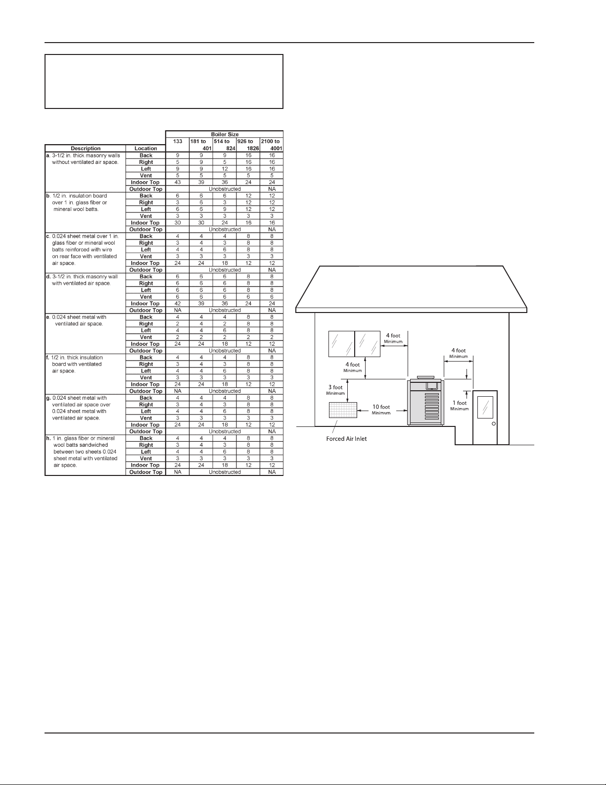
Clearances
All dimensions are in inches.
Derived from National Fuel Gas Code, Table 6.2.3(a)
*Vent includes factory-supplied drafthood and does not include fieldsupplied vent systems above the drafthood. On Models 2100-4001
drafthood is built into boiler.
Table C: Clearances from Combustible Surfaces
* Models with factory-installed floor shield as standard.
BOLD type indicates Low NOx models.
Table B: Combustible Floor Shield Ordering
Information
NOTE 1: Combustible floor shield is required when
boiler is to be installed on a combustible surface. (See
ordering information in Table B.)
NOTE 2: Servicing Clearances: Provide at least 24"
(Models 133-1826), 48" (Models 2100-4001) in front of
unit for removal and servicing of the Controls & Burner
Tray. Provide at least 18" on side opposite water
connections for deliming of Heat Exchanger Tubes.
7
NOTE: The boiler shall be installed in a space large
n comparison to the size of the boiler. Large space
i
is defined as having a volume at least sixteen (16)
times the total volume of the boiler.
Outdoor Boilers
These boilers are design certified for outdoor installation. Boilers must not be installed under an overhang
within three (3) feet from the top on the boiler. Three
(3) sides must be open in the area under the over-
ang. Roof water drainage must be diverted away
h
from the boilers with the use of gutters.
The point from where the flue products exit the boiler
must be a minimum of four (4) feet below, four (4) feet
horizontally from or one (1) foot above any door, window or gravity inlet to a building. The top surface of the
boiler shall be at least three (3) feet above any forced
air inlet, or intake ducts located within ten (10) feet horizontally.
Derived from National Fuel Gas Code, Table 6.2.3(b)
Table D: Reduction of Clearances to Protected
Surfaces
Fig. 3: Minimum Distances to Building Openings from
Where Flue Products Exit the Boiler
High-Wind Conditions (Outdoor Units Only)
In areas where high winds are frequent, it may be necessary to locate the boiler a minimum of 3' from high
vertical walls, or install a wind break so the boiler is not
in direct wind current.
Combustion and Ventilation Air
(Indoor Units Only)
The boiler must have both combustion and ventilation
air. Minimum requirements for net free air supply
openings are 12 inches from ceiling for ventilation and
12 inches from the floor for combustion air as outlined
in Z223.1 - latest edition and any local codes that may
have jurisdiction.
8
CAUTION: Combustion air must not be
(Part of heater)
ontaminated by corrosive chemical fumes which
c
can damage the boiler and void the warranty.
Venting
Outdoor Installations
a. All Air From Inside The Building:
Each opening shall have a minimum net free
square inches as noted in Table E.
Model Sq. Inches Model Sq. Inches
133 136 1125 1125
182/181 181 1223 1223
260/261 264 1336 1337
330/331 334 1468 1467
400/401 399 1631 1630
514 512 1826 1826
624 627 2100 2100
724 726 2500 2499
824 825 3001 3000
962 962 3500 3500
4001 4000
Table E: Minimum Net Free Air from Inside Building
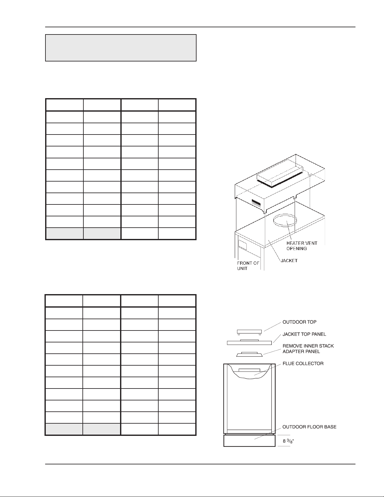
Model 133
1. Remove the front (4) screws.
2. Line up outdoor top vent opening over heater vent
opening.
3. Lower outdoor top onto unit lining up slots in the
outdoor top with screw holes in jacket top.
4. Reinstall (5) screws to secure jacket top and outdoor top to unit.
b. All Air From Outdoors:
When air is supplied directly from outside of building, each opening shall have a minimum net free
square inches as noted in Table F.
Model Sq. Inches Model Sq. Inches
133 34 1125 282
182/181 46 1223 306
260/261 66 1336 335
330/331 84 1468 367
400/401 100 1631 408
514 128 1826 457
624 157 2100 525
724 182 2500 625
824 207 3001 750
962 241 3500 875
4001 1000
Fig. 4: Installing Outdoor Top—Model 133
Models 181-401 & 182-400
Outdoor Top Installation
Table F: Minimum Net Free Air from Outside Building
Fig. 5: Installing Outdoor Top—Models 181-401 & 182-
400
9
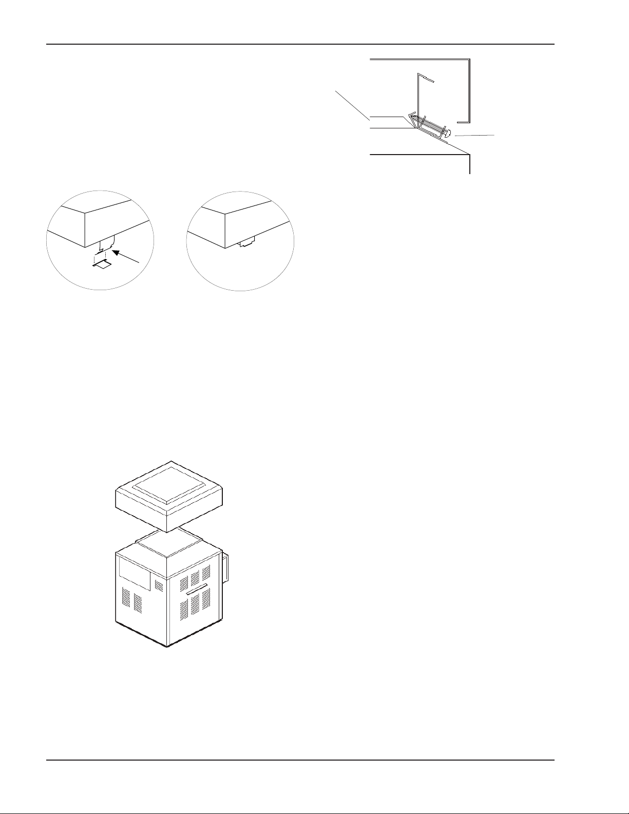
1. Remove jacket top panel.
Outdoor Top
(Shipped Loose with Heater)
Detail A Detail B
JACKET TOP
F
ASTENING
SCREW
2. Remove and discard inner stack adapter panel.
3. Install jacket top panel.
4. Insert tabs of outdoor top into keyholes located on
jacket top panel (4 places). See Detail A.
5. Snap tabs on outdoor top into the locked position
of the keyhole so the top will not pull out. See
Detail B.
Fig. 8: Installing Outdoor Top Detail—Models 514–824
Models 926-1758
Boilers are shipped with outdoor vent terminal factory
installed.
Indoor Installations
Model 133
1. Shut-off main electrical power switch to boiler.
Fig. 6: Installing Outdoor Top—Models 181-401 & 182-
400
Models 514-824
1. Lower outdoor top onto unit. Position top so it is
centered on unit from side to side and front to rear.
2. Turn heater manual switch located in upper control
panel to the "OFF" position.
3. Shut-off gas supply and water supply to the boiler.
4. Mount drafthood on boiler and attach with the
sheet metal screws provided. Drafthood should be
positioned with the vent sensor located on the
front left side (see next page).
5. Remove plastic plug from left side of boiler jacket
and install the plastic grommet provided.
6. Route flue sensor wire harness through the grommet installed in Step 5.
7. Remove door and locate wire from roll-out sensor
to high limit with the male/female connector.
8. Disconnect male/female connector and attach to
the 2 wires from drafthood vent sensor harness.
2. Tighten the (4) screws (as indicated in Fig. 8) until
Fig. 7: Installing Outdoor Top—Models 514–824
they come in contact with the unit jacket top, then
evenly tighten all (4) screws to secure to unit.
10
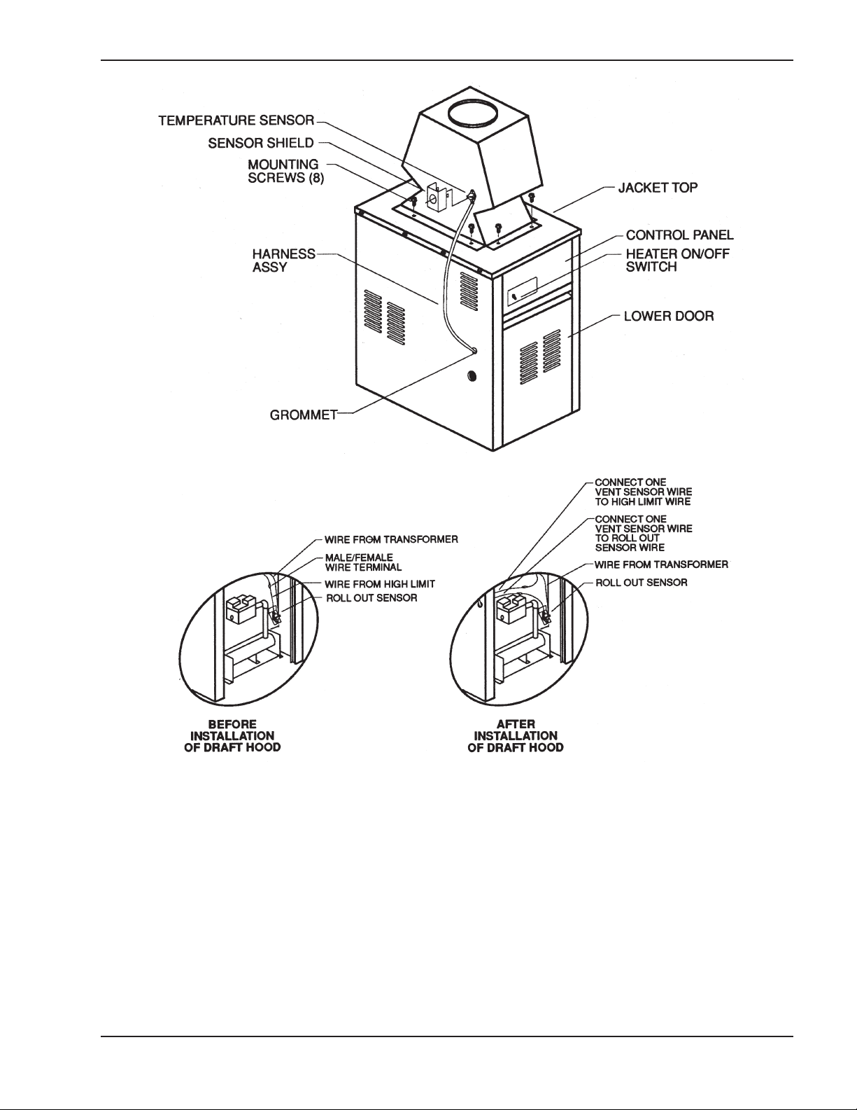
Fig. 9: Indoor Installation—Model 133
Models 181-401 & 182-400
Indoor Stack Installation
1. Remove the louvered jacket top by removing four
(4) #10 flathead screws.
2. If originally installed, remove outdoor top from the
louvered jacket top.
3. Place the inner stack adapter panel over the flue
collector inside the heater. Make sure the flanged
side of the flue opening is up.
4. Turn the stack (drafthood) upside down and set it
down bottom side up.
5. Turn the jacket top panel (removed in step 1)
upside down and place it over the stack.
6. Attach the three (3) mounting brackets to the stack
using the screws provided and the holes that are
pre-drilled in the stack. Make sure the brackets
are positioned with the flange near the top side
of the stack (see Fig. 10). Caution must be
taken not to over tighten and strip the screw
threads.
11
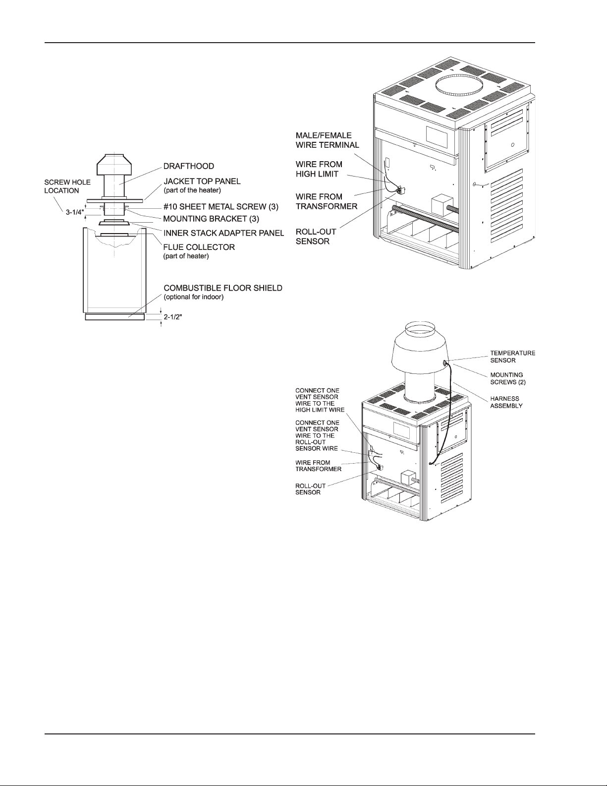
7. Turn the assembled stack and jacket top, rightside
up. The jacket top will be trapped between the
brackets and the top of the stack. Place the stack
over the inner stack adapter panel flanged hole
and lower the louvered jacket top panel back into
its original position. Reinstall the four (4) #10 flathead screws removed in step 1 above.
Fig. 10: Indoor Installation—Models 181-401 & 182-400
Fig. 11: Boiler Before Drafthood Installation—Models
181-401 & 182-400
Models 181-401 & 182-400
1. Shut-off main electrical power switch to boiler.
2. Turn heater manual switch located in upper control
panel to the "OFF" position.
3. Shut-off gas supply and water supply to the boiler.
4. Mount drafthood on top of boiler as shown in Fig.
12. Drafthood should be positioned with the vent
sensor located on the front right side as shown.
5. Remove plastic plug from left side of boiler jacket
and install plastic grommet provided.
6. Route flue sensor wire harness through the grommet installed in Step 5.
7. Remove door and locate wire from roll-out sensor
to high limit with the male/female connector.
8. Disconnect male/female connector and attach to
the 2 wires from drafthood vent sensor harness.
Fig. 12: Boiler After Drafthood Installation—Models
181-401 & 182-400
Models 514-824
Locate and assemble as shown in Fig. 13. Secure with
screws supplied in envelope in carton.
12
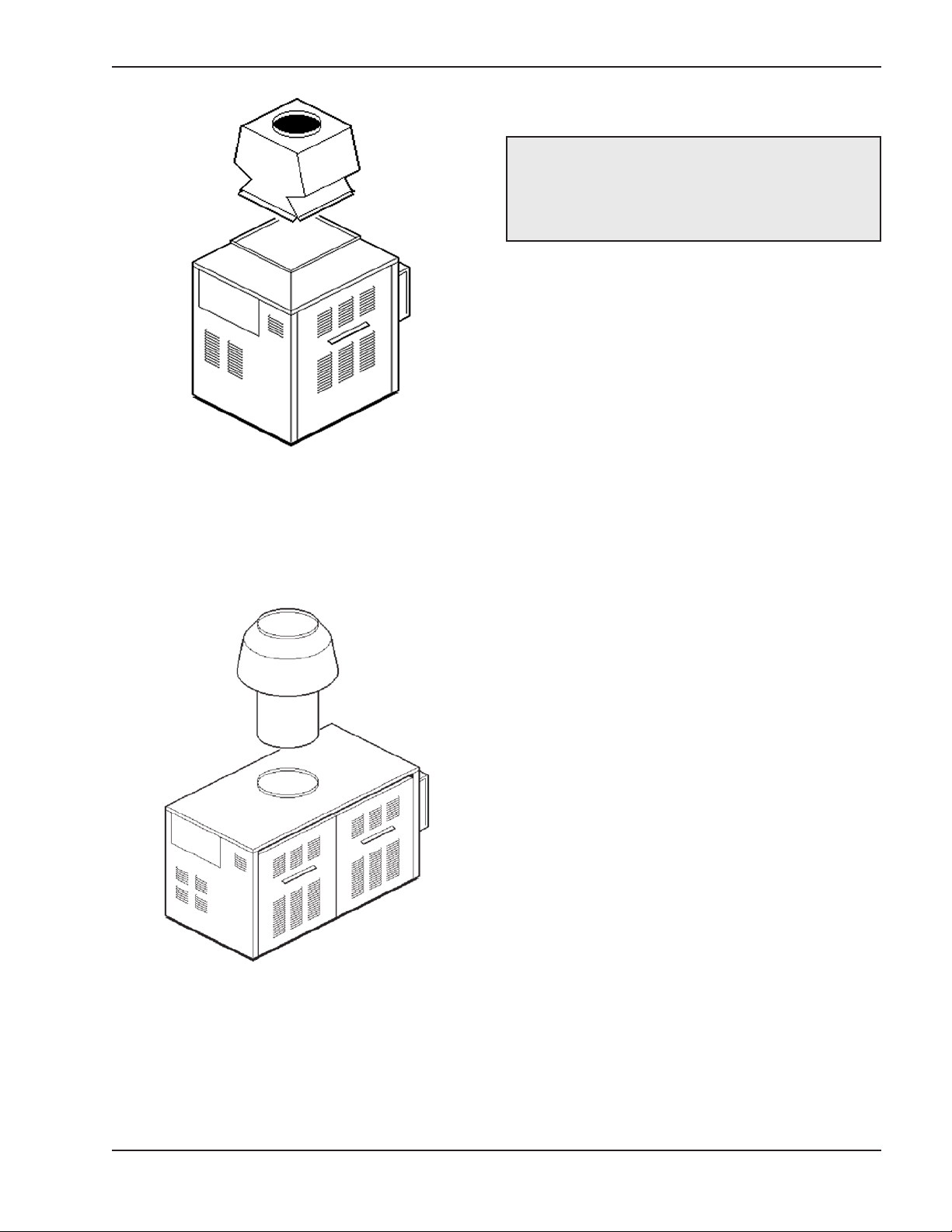
Fig. 13: Drafthood Installation—Models 514–824
Models 962-1826
Locate and assemble as shown in Fig. 14. Secure with
screws supplied in envelope in carton.
Vent Piping
WARNING: Indoor boilers require a drafthood
that must be connected to a vent pipe and properly
vented to the outside. Failure to follow this
rocedure can cause fire or fatal carbon monoxide
p
poisoning.
Vent piping the same size or larger than the drafthood
outlet is recommended, however, when the total vent
height is at least 10 ft. (drafthood relief opening to vent
terminal), the vent pipe size may be reduced as specified in Chapter 10 of the latest edition of the National
Fuel Gas Code, ANSI Z223.1.
As much as possible, avoid long horizontal runs of
vent pipe and too many elbows. If installation requires
horizontal non-vertical runs, the vent pipe must have a
minimum of 1/4 inch per foot rise and should be supported at not more than 5 ft. intervals. Plumbers tape,
criss-crossed, will serve to space both horizontal and
vertical piping.
Gas vents supported only by the flashing and extending above the roof more than 5 ft. should be securely
guyed or braced to withstand snow and wind loads.
Fig. 14: Drafthood Installation—Models 962–1826
Models 2100-4001
These models have built-in drafthoods. For proper
operation, the drafthood outlet must be connected to
the venting system.
We recommend the use of insulated vent pipe spacers
through the roof and walls.
For protection against rain or blockage by snow, the
vent pipe must terminate with a vent cap which complies with the local codes or, in the absence of such
codes, to the latest edition of the National Fuel Gas
Code, ANSI Z223.1.
The discharge opening must be a minimum of 2 ft. vertically from the roof surface and at least 2 ft. higher
than any part of the building within 10 ft.
Vent stack shall be at least 5 ft. in vertical height above
the drafthood outlet. The vent cap location shall have
a minimum clearance of 4 feet horizontally from, and
in no case above or below, unless a 4-foot horizontal
distance is maintained, from electric meters, gas
meters regulators and relief equipment.
The weight of the vent stack or chimney must not rest
on boiler drafthood. Support must be provided in compliance with applicable codes. The boiler top and
drafthood must be readily removable for maintenance
and inspection. Vent pipe should be adequately supported to maintain proper clearances from combustible
construction.
13

Type "B" double-wall or equivalent vent pipe is recom-
5' MIN
2' MIN
10' OR LESS
2' MIN
VENT CAP
VENT PIPE
DRAFT HOOD
H
EATER
mended. However, single-wall metal vent pipe may be
used as specified in the latest edition of the National
Fuel Gas Code ANSI Z223.1.
Manifolds that connect more than one boiler to a common chimney must be sized to handle the combined
load. Consult available guides for proper sizing of the
manifold and the chimney. At no time should the area
be less than the area of the largest outlet.
Fig. 16: Venting Clearances
hoods and bathroom exhausts, so they will operate at maximum speed. Do not operate a summer
exhaust fan. Close fireplace dampers.
Fig. 15: Common Venting
At the time of removal of an existing boiler, the following steps shall be followed with each appliance
remaining connected to the common venting system
placed in operation, while the other appliances remaining connected to the common venting system are not
in operation.
(a) Seal any unused openings in the common venting
system.
(b) Visually inspect the venting system for proper size
and horizontal pitch and make sure there is no
blockage or restriction, leakage, corrosion and
other deficiencies which could cause an unsafe
condition.
(c) As much as possible, close all building doors and
windows and all doors between the space in which
the appliances remaining connected to the common venting system are located and other spaces
of the building. Turn on clothes dryers and any
appliance not connected to the common venting
system. Turn on any exhaust fans, such as range
(d) Place in operation the appliance being inspected.
Follow the lighting instructions. Adjust thermostat
so appliance will operate continuously.
(e) Test for spillage at the drafthood relief opening
after 5 minutes of main burner operation. Use the
flame of a match or candle, or smoke from a cigarette, cigar or pipe.
(f) After it has been determined that each appliance
remaining connected to the common venting system properly vents when tested as outlined above,
return doors, windows, exhaust fans, fireplace
dampers and any other gas burning appliance to
their previous conditions of use.
(g) Any improper operation of the common venting
system should be corrected so that the installation
conforms with the latest edition of the National
Fuel Gas Code, ANSI Z223.1. When re-sizing any
portion of the common venting system, the common venting system should be re-sized to
approach the minimum size as determined using
the appropriate tables in Part 11 of the National
Fuel Gas Code, ANSI Z223.1.
For special venting applications that require reduced
vent sizes and through-the-wall venting, the Type D
Induced Draft Assembly can be used. Consult the factory or your local Raypak representative.
14
 Loading...