

Nieco 615E Parts List

AUTOMATIC
FOODSERVICE
EQUIPMENT
FLEXI-CHEF SYSTEM
®
AUTOMATIC ELECTRIC BROILER
MODEL 615E
OPERATING
INSTRUCTIONS
IMPORTANT: RETAIN THIS MANUAL IN A SAFE PLACE FOR FUTURE REFERENCE.
Broiler area must be kept free of combustible materials, and the flow of combustion and ventilation air
must not be obstructed. Operating personnel must not perform any maintenance or repair functions.
Contact your Nieco Authorized Dealer.
TABLE OF CONTENTS
INSTALLATION . . . . . . . . . . . . . . . . . . . . . . . . . . . . . . . . . . . . . . . . . . . . . . . . . . . . . . . . . .2
CONTROLS AND INDICATORS . . . . . . . . . . . . . . . . . . . . . . . . . . . . . . . . . . . . . . . . . . . . .3
PARTS AND LOCATION . . . . . . . . . . . . . . . . . . . . . . . . . . . . . . . . . . . . . . . . . . . . . . . . . . .4
CLEANING INSTRUCTIONS . . . . . . . . . . . . . . . . . . . . . . . . . . . . . . . . . . . . . . . . . . . . . . . .6
CONVEYOR BELT REMOVAL . . . . . . . . . . . . . . . . . . . . . . . . . . . . . . . . . . . . . . . . . . . . . .7
WIRING DIAGRAM . . . . . . . . . . . . . . . . . . . . . . . . . . . . . . . . . . . . . . . . . . . . . . . . . . . . . . . .8
TROUBLE SHOOTING GUIDE . . . . . . . . . . . . . . . . . . . . . . . . . . . . . . . . . . . . . . . . . . . . . .9
SPECIFICATIONS . . . . . . . . . . . . . . . . . . . . . . . . . . . . . . . . . . . . . . . . . . . . . . . . . . . . . . .11
FOR YOUR SAFETY:
Do not store or use gasoline or other flammable vapors or
liquids in the vicinity of this or any other appliance.

2
INSTALLATION
PRE-INSTALLATION
Uncrate the broiler, and inspect for shipping damage. Contact the factory if there is obvious damage. Remove the
tape securing the machine parts, and install the parts in their proper location. If you find concealed damage to any
part of this unit, contact your freight carrier immediately. The factory warranty does not cover freight damage.
MOUNTING
If the broiler was shipped with a tubular stand, refer to separate tubular stand assembly instructions.
Note: The four legs of the broiler stand are equipped with casters. Always set the brakes on the casters to
prevent the broiler from shifting during operation or cleaning.
HOOD REQUIREMENTS
This appliance must be installed under a ventilation hood of adequate size and capacity (approximately 400 CFM).
The hood should be at least 6" larger in all dimensions than the appliance top, and be 12" to 18" above the top. Do
not obstruct the flow of combustion and ventilation air. An adequate air supply must be available for safe and proper
operation.
Note: See the National Fire Prevention Association booklet on ventilation of cooking equipment. Write to:
NFPA, 470 Atlantic Ave., Boston, MA 02210. Local codes on venting must also be complied with.
CLEARANCE
For proper installation, the minimum clearance from combustible and non-combustible construction is 6" from the
back and 6" from the front of the machine. Keep appliance area free from combustibles.
To facilitate disassembly and service of the unit a minimum of 24" should be allowed on each end of the broiler to
allow the drip trays and reflectors to be removed.
ELECTRICAL CONNECTION
Power requirements are stated on the unit nameplate and must be connected accordingly. Before starting broiler,
tighten all electrical connections in control box.
Note: This appliance must be electrically grounded in accordance with local codes or in the absence of local
codes, the National Electrical Code, ANSI/NFPA No. 70-1990. In Canada, in accordance with the Canadian
Electrical Code CSA 22.1 part 1, or local codes.
WARNING: This appliance should be connected with a five-wire (3 phase, neutral, ground) plug for
your protection against shock hazard. Be sure to plug directly into a properly grounded five-prong
receptacle. Do not cut or remove grounding prong from plug.
Note:
This appliance cannot be safely operated in the event of a power failure. No attempt should be made
to operate during a power failure. Disconnect power supply before servicing.
PRE-OPERATION CHECK
Be sure that all parts are installed in the proper location. Refer to OPERATION section for starting procedure. Start
broiler and test for proper operation.

3
CONTROLS AND INDICATORS
MODEL 615E OR 815E
A. 5 Amp fuse D. Digital Speed Controller (2 - 615, 3 - 815)
B. Power On Indicator Light (Red) E. Motor On/Off Switches (White) (2 - 615, 3 - 815)
C. Main Power On/Off Switch (Red)
STARTING PROCEDURE
Before starting broiler, ensure that all parts are installed in the proper location, the plug is properly
inserted in the socket, and the ventilation hood is turned on.
1. Turn on the power to the broiler by pulling out the red On/Off switch (C).
2. Turn on the motor switches (E) and set the cook times on the digital speed controller (D).
SHUTDOWN PROCEDURE
For EMERGENCY Shutdown, turn the Main Power Switch off. (PUSH Red Switch in.)
For planned shutdowns, perform the following procedure:
1. Clear machine of all food products.
2. Turn Main Power Switch off.
3. Turn Motor Switches off.
CAUTION: Always turn machine completely off before unplugging power cord.
CAUTION: Allow machine to cool before removing any parts.
A
B
C
DE
4
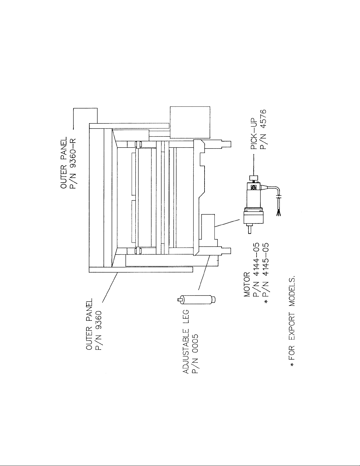
PARTS AND LOCATION
MODEL 615E - FEED END VIEW
 Loading...