


AUTOMATIC
FOOD SERVICE
EQUIPMENT
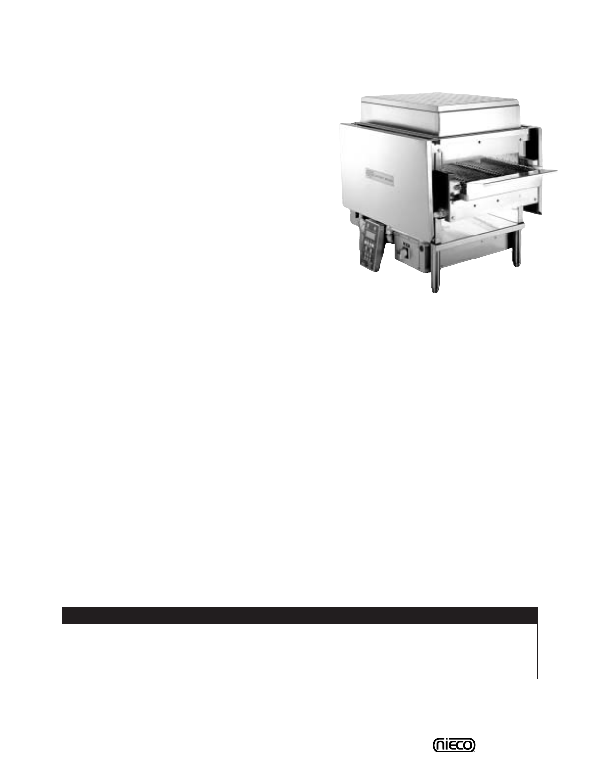
AUTOMATIC GAS BROILER
MODEL N1731 AND N1725
OWNERS MANUAL
IMPORTANT: RETAIN THIS MANUAL IN A SAFE PLACE
FOR FUTURE REFERENCE.
Broiler area must be kept free of combustible materials, and the flow of combustion and ventilation air must not
be obstructed. Operating personnel must not perform any maintenance or repair functions. Contact your Nieco
Authorized Dealer.
In a prominent location, post instructions to be followed in the event the user smells gas.This information shall
be obtained by consulting your local gas supplier.
FOR Y OUR SAFETY:
Do not store or use gasoline or other flammable vapors or liquids in
the vicinity of this or any other appliance.
WARNING: Improper installation, adjustment, alteration, maintenance
can cause property damage, injury, or death. Read the installation,
operating and maintenance instructions thoroughly before installing
or servicing this equipment.

2
Table of Contents
A. General Information....................................................................................................................3
A.1 Description..........................................................................................................................3
A.2 Warranty Information...........................................................................................................3
A.3 Service/Technical Assistance .............................................................................................4
A.4 Important Safety Information ..............................................................................................4
B. Machine Installation ...................................................................................................................6
B.1 Pre-Installation...................................................................................................................6
B.2 Mounting............................................................................................................................6
B.3 Leveling..............................................................................................................................6
B.4 Hood Requirements ...........................................................................................................6
B.5 Clearance...........................................................................................................................6
B.6 Gas Connection.................................................................................................................6
B.7 Electrical Connection.........................................................................................................7
B.8 Pre-Operation Check.........................................................................................................7
B.10 Installing Gas Connectors.................................................................................................8
C. Operation.....................................................................................................................................9
C.1 Controls and Indicators.......................................................................................................9
C.2 Step-by-Step Lighting Procedure......................................................................................10
C.3 Shutdown Procedure........................................................................................................11
C.4 Control Operation .............................................................................................................12
C.5 Assembly/Disassembly & Cleaning ..................................................................................17
D. Conveyor Chain Removal........................................................................................................22
E. Troubleshooting........................................................................................................................23
F. Model 1725 Parts & Locations ................................................................................................25
G. Specifications...........................................................................................................................27
H. Wiring Diagram............................................................................................................... ..........29
I. Warranty Information ...............................................................................................................30
Model 1725/1731
3 Model 1725/1731
A. GENERAL INFORMATION
A1. Description
The Nieco N Series Broilers have been designed with flexibility, and ease of use in mind.The Models 1731 and 1725
feature dual belt, electric elements on top and high release
convection burners on the bottom.This combination of gas
and electric broiling gives the operator more broiler control
than ever before.The 1731 & 1725 are designed to broil a
wide variety of products.
This manual provides the safety, installation and operating
procedures for the Nieco Automatic Broiler Models N1725 &
N1731.We recommend that all information contained in this
manual be read prior to installing and operating the broiler.
A2. Warranty Information
Please read the full text of the limited Warranty in this manual.
If the unit arrives damaged, contact the carrier immediately and file a damage claim with them. Save all
packing materials when filing a claim. Freight damage claims are the responsibility of the purchaser and
ARE NO T covered under warranty.
The warranty
does not extend to:
• Damages caused in shipment or damage as a result of improper use.
• Installation of electrical service.
• Normal maintenance as outlined in this manual.
•Malfunction resulting from improper maintenance.
• Damage caused by abuse or careless handling.
•Damage from moisture into electrical components.
• Damage from tampering with or removal of any safety device.
IMPORTANT! Keep these instructions for future reference. If the unit changes ownership,
be sure this manual accompanies the equipment.
IMPORTANT
The Nieco Corporation reserves the right to change specifications and product design without
notice. Such revisions do not entitle the buyer to corresponding changes, improvements, additions
or replacements for previously purchased equipment.
4 Model 1725/1731
A3. Service/Technical Assistance
If you experience any problems with the installation or operation of your broiler, contact your local
Authorized Nieco Distributor.
Fill in the information bellow and have it handy when calling your authorized service agency for assistance.
The serial number is on the broiler rating plate on the side of the unit.
Purchased from:
Date of Purchase:
Model No.:
Serial No.:
For the name of your local Authorized Nieco Distributor, please call (800) 821-2141.
Use only genuine Nieco replacement parts in your broiler.Use of replacement parts other than those sup-
plied by Authorized Nieco Distributors and Service Agencies will void the warranty.Your local Authorized
Nieco Distributor and Service Agent has been factory trained and has a complete supply of parts for your
automatic broiler.
You may contact the factory direct at (707) 284-7100 if you have trouble locating your local Nieco
Distributor.
A. GENERAL INFORMATION (Continued)
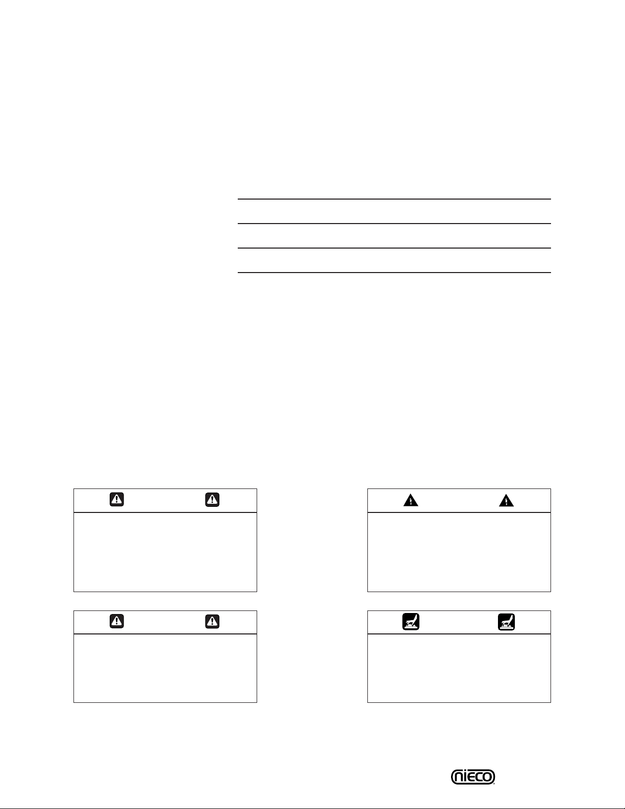
A4. Important Safety Information
Throughout this manual, you will find the following safety words and symbols that signify important safety
issues with regards to operating or maintaining the equipment:
WARNING
GENERAL WARNING. Indicates
information important to the proper
operation of the equipment. Failure
to observe may result in damage to
the equipment and/or severe bodily
injury or death.
WARNING
ELECTRICAL WARNING. Indicates
information relating to possible
shock hazard. Failure to observe
may result in damage to the equipment and/or severe bodily injury or
death.
CA UTION
GENERAL CAUTION. Indicates
information important to the proper
operation of the equipment. Failure
to observe may result in damage to
the equipment.
WARNING
HOT SURFACE WARNING. Indicates
information important to the handling of equipment and parts.
Failure to observe caution could
result in personal injury.

5 Model 1725/1731
A4. Important Safety Information (Continued)
In addition to the warnings and cautions in this manual, use the following guidelines for safe operation of
your Nieco Automatic Broiler:
• Read and follow all instructions before using this equipment.
• Install or locate broiler only for its intended use as described in this manual.
•Do not operate this equipment if it has a damaged cord or plug, if it is not working properly or if it
has been otherwise damaged.
• This equipment should only be serviced by authorized personnel. Contact your local Nieco
Distributor for adjustment or repair.
• Use only genuine Nieco replacement parts for your broiler. Failure to do so will void the warranty
and may damage the broiler.
The following warnings and cautions appear throughout the manual and should be carefully
observed:
•Turn the broiler off, and close the main gas valve and disconnect the power cord before
performing any service, maintenance or cleaning on the broiler.
•Always allow the broiler to fully cool before performing any service, maintenance or
cleaning. Failure to wait for the broiler to cool fully may result in personal injury.
• The procedures in this manual may include reference to the use of chemical products.The
Nieco Corporation does not endorse the use of any particular cleaning/degreasing agent.
• The broiler should be grounded according to local electrical codes to prevent the
possibility of electrical shock. It requires a grounded receptacle with separate electrical
lines, protected by fuses or circuit breakers of the proper rating.
•All electrical connections must be in accordance with local electrical codes and any other
applicable codes.
• The use of adequate ventilation (as rated in this manual) with this broiler is mandatory.
Failure to adequately ventilate this unit and provide safe operating distances (as specified
in this manual) is a fire safety hazard. Follow the instructions for emergency broiler
shutdown in the event of an emergency.
WARNING ELECTRICAL SHOCK HAZARD. F AILURE T O FOLLOW THESE INSTRUCTIONS COULD
RESULT IN SERIOUS INJURY OR DEATH:
_
Electrical ground is required on this appliance.
_
Check with a qualified electrician if you are in doubt as to whether the appliance is properly
grounded.
_
Do not use water on or near the control box located on the side of the broiler for risk
of serious injury or death due to electrical shock.
WARNING, HIGH TEMPERATURES WITH HOT SURFACES. FAILURE TO FOLLOW THESE PROCEDURES COULD RESULT IN SERIOUS INJURY:
_
Do not attempt to clean, disassemble or perform maintenance on this broiler until it is fully
cooled as per the instructions contained in this manual.
A. GENERAL INFORMATION (Continued)
6 Model 1725/1731
B. INSTALLATION
B.1 Pre-Installation
Uncrate the broiler and inspect for shipping damage. Remove the tape securing the machine parts, and
install the parts in their proper location. Refer to the Parts and Location section of this manual. If there
are obvious or concealed damages to any part of the broiler, please contact your freight carrier.The factory warranty does not cover freight damage.
B.2 Mounting
Follow the mounting instructions if this function is not performed by the installer.
B.3 Leveling
The grease drain system is based on a gravity-flow design. Therefore, it is extremely important to level
the broiler during installation.
B.4 Hood Requirements
This appliance must be installed under a ventilation hood of adequate size and the following minimum
capacity:
Model SCFM
1725 800
1731 800
Do not obstruct the flow of combustion and ventilation air. An adequate air supply must be available for
safe and proper operation.
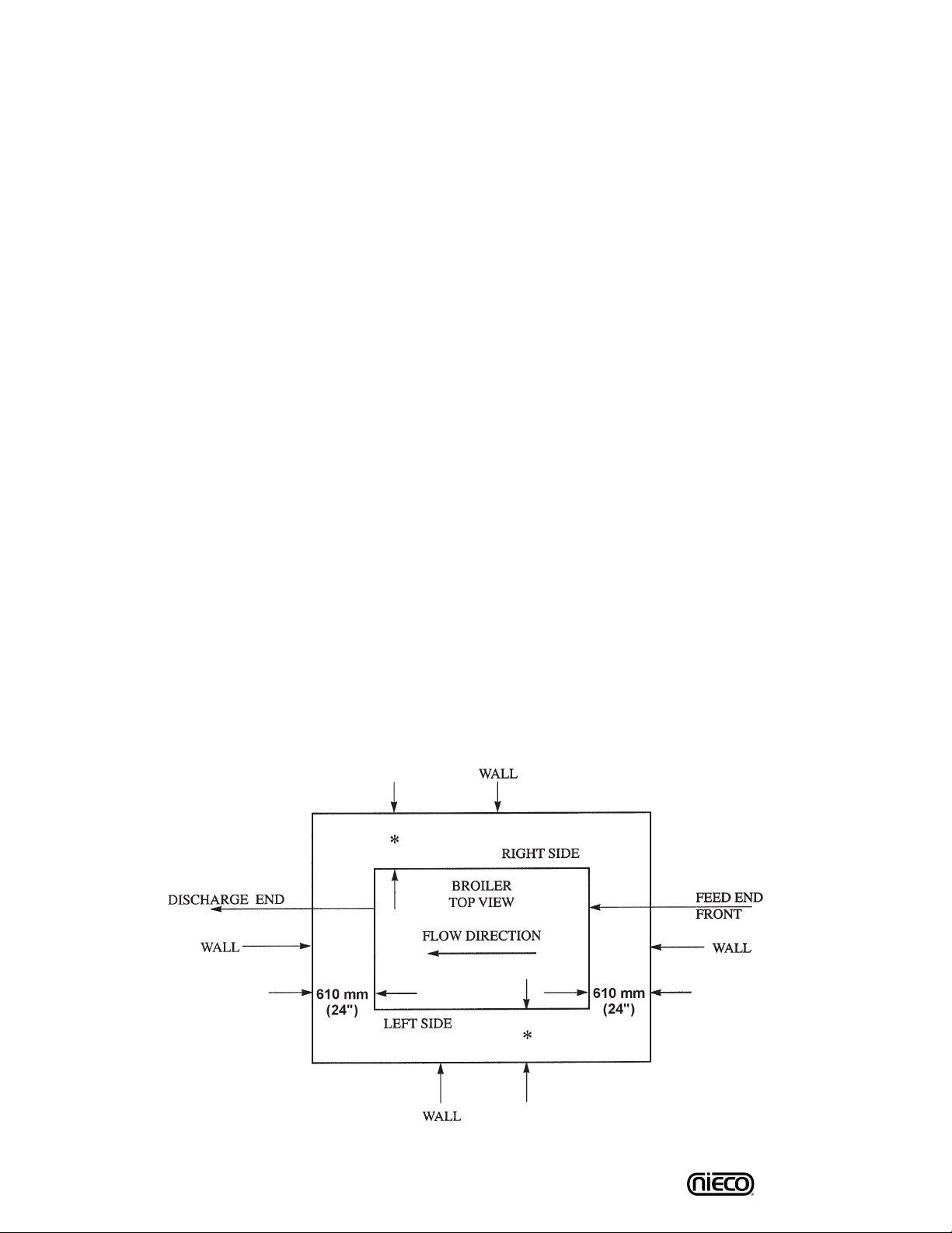
B.5 Clearance
For proper installation the minimum clearance from combustible and non-combustible construction must
be 152 mm (6”) from the back and 152 mm (6”) from the front of the machine.Keep appliance area free
from combustibles.
To facilitate disassembly and service of the unit a minimum of 610 mm (24”) should be allowed on the
control panel (feed end) of the broiler, as well as in front and back of the broiler.
B.6 Gas Connection- 3/4” N.P.T.
At rated input the gas supply should deliver a pressure of at least 15 mbar (6" water column) at the
broiler connection for natural gas.Incoming gas supply pressure must not exceed 50 mbar (20" water
column).
*
152 mm (6”) Minimum, preferably 610 mm (24”) or more for service. Location clearances are from walls of broiler height.

7 Model 1725/1731
Note: Appliance installation must conform with all local codes. Check all fittings for gas leaks,
including pilot tubing and inlet connections as soon as the appliance is connected to the gas
supply.
Note: This appliance must be isolated from the gas supply piping system during any pressure
testing of the gas supply piping system with test pressure of 3.45 kPa (0.5 psig) or more.
B.7 Electrical Connection
Power requirements are stated on the unit nameplate and must be connected accordingly.Before starting broiler, tighten all electrical connections in control box. An electrical wiring diagram can be found
inside the control box.
Note: Disconnect power before servicing.
B.8 Pre-Operation Check
Be sure that all parts are installed in the proper location:
❏ Ventilation is turned on
❏ Broiler is plugged in
❏ Gas line is connected
8 Model 1725/1731
INSTALLING GAS APPLIANCE CONNECTORS
AND FLEXIBLE GAS LINES CORRECTLY
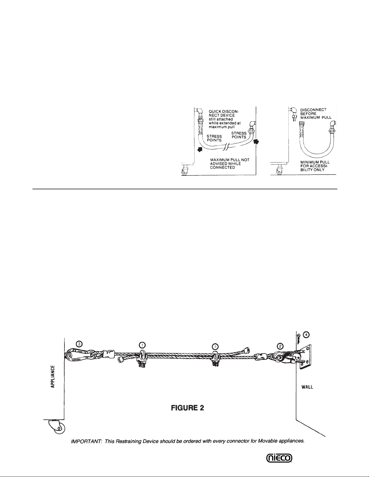
RESTRAINING DEVICE
INSTALLATION AND USE
This high strength restrainer is to be used with all moveable (castered) appliances. It fully complies with
American Gas Association requirements. References: Z21.69, Z83.11, and Z21.41 with current revisions.
Installation is quick and positive.In Canada, device is in accordance with CAN 1-6.9-M70 Quick
Disconnect Devices for use with gas fuel, and CAN 1-6.10-88 metal connectors for gas appliances.
Correct length for any appliance is simply a matter of loosening two adjuster clips (1) and re-tightening.
(3" to 6" shorter than appliance connector is desired length.)
Restrainer is made of heavy duty steel cable, with a strong scissor hood (2) at one end, and an equally
strong spring hook (3) at the other.Cotter pin (4) is supplied to secure the installation.
For safety in the kitchen area, and to insure maximum service life, it is vitally important to correctly
install connectors.
In order to avoid sharp kinks or excessive bends
that could have a damaging effect on the connector, it may be necessary to attach pipe elbows in
order to bring the connector into its proper plane.
For easy movement of the appliance, the connector should be installed with a "lazy" loop for minimum tension.
Note: Gas appliances should be disconnected
prior to maximum movement. (Minimal movement is possible to connect hose.)
WRONG
Avoid sharp bends and
kinks when pulling equipment away from wall.
RIGHT
Minimum pull of equipment is permissible for
accessibility to quick disconnect device.
9 Model 1725/1731
C. OPERATION
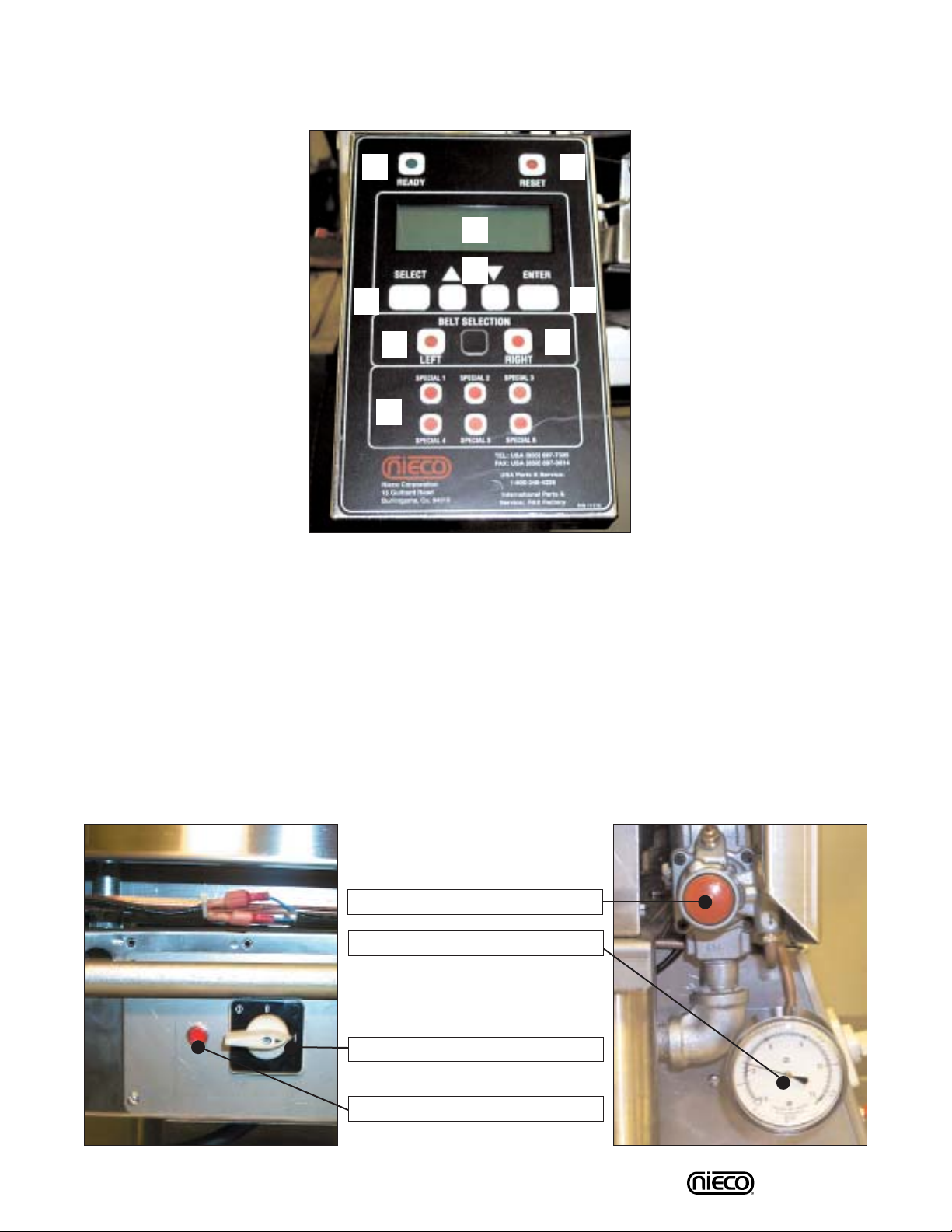
Controls and Indicators
MAIN ON/OFF SWITCH
GAS SYSTEM
PUSHBUTTON SAFETY VALVE
GAS PRESSURE GAUGE
IGNITION RESET SWITCH
CONTROL PAD
A. READY LIGHT - Indicates broiler is on
B. RESET - Use to reset certain control functions
C. LED Display
D. UP/DOWN ARROW KEYS - For cursor movement
E. SELECT - Make control selections
F. ENTER
G. LEFT - For selecting the left belt
H. RIGHT - For selecting the right belt
I. PRESET BUTTONS - For selecting preset settings for
different products
A B
C
D
F
E
G
H
I
10 Model 1725/1731
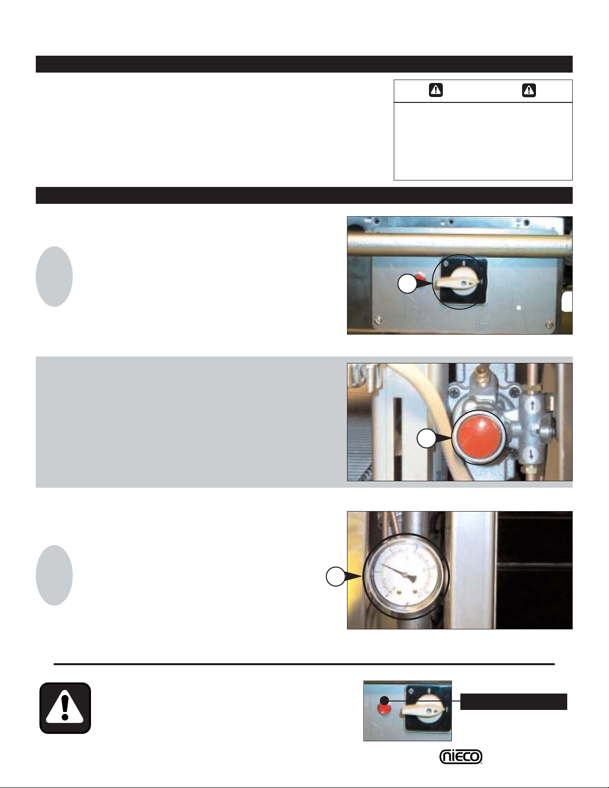
a
C.1 Lighting Procedures
1. Broiler is
centered under
hood and
plugged in
2. Gas valve is
open when
handle is in line
(parallel to) the
pipe
3. Tur n ventilation
system on
PILOTS MUST BE LIT WITHIN 2 MINUTES; IF
YOU EXCEED 2 MINUTES, PRESS THE RESET
BUTTON NEXT TO THE ON/OFF SWITCH AND
REPEAT IGNITION PROCEDURES
Reset Button
1
Turn the MAIN POWER SWITCH (a) on.
2
Push and hold the SAFETY PUSH BUTTON
VALVE (a) for 30 seconds. Release and verify that
the burners have lit.
3
Check the GAS PRESSURE GAUGE (a), verify that
it reads 4’.
Allow the broiler 30 minutes to
warm up.
WARNING
THE VENTILATION SYSTEM MUST
BE ON AT ALL TIMES DURING
BROILER OPERATION. OPERATING
BROILER WITHOUT PROPER
VENTILATION IS A SEVERE FIRE
HAZARD.
IGNITION PROCEDURES
PRE-LIGHTING PREPARATION
a
a
 Loading...