


Nieco 1450 User Manual
AUTOMATIC
FOODSERVICE
EQUIPMENT
AUTOMATIC CHAR BROILER
MODEL 1424/1450 GAS - “B” Series
OWNER’S MANUAL
IMPORTANT: RETAIN THIS MANUAL IN A SAFE PLACE
FOR FUTURE REFERENCE.
Broiler area must be kept free of combustible materials, and the flow of combustion and ventilation air must not
be obstructed. Operating personnel must not perform any maintenance or repair functions. Contact your Facilities
Maintenance Department.
In a prominent location, post instructions to be followed in the event the user smells gas. This information shall be
obtained by consulting your local gas supplier.
FOR YOUR SAFETY:
Do not store or use gasoline or other flammable vapors or liquids in
the vicinity of this or any other appliance.
WARNING: Improper installation, adjustment, alteration, maintenance
can cause property damage, injury, or death. Read the installation,
operating and maintenance instructions thoroughly before installing
or servicing this equipment.


1
TABLE OF CONTENTS
A. General Specifications.................................................................................................................2
B. Machine Installation.....................................................................................................................5
Pre-Installation
Mounting
Hood Requirements
Clearance
Gas Connection
Electrical Connection
Pre-Operation Check
Gas Connectors and Restraining Device
C. Operation ......................................................................................................................................8
Controls and Indicators
Gas System Controls
Step-by-Step Lighting Procedure
Shutdown Procedure
Automatic Temperature Control
ATC Temperatures
Broiler Set-up Chart
Bun Platen Adjustment
D. Assembly/Disassembly and Cleaning........................................................................................13
E. Conveyor Belt Removal...............................................................................................................17
F. Conveyor Belt Tension................................................................................................................18
Broil Belt Problems
G. Parts and Location.......................................................................................................................19
Model 1424
H. Trouble Shooting Guide ..............................................................................................................22
I. Wiring Diagrams...........................................................................................................................24
2
A. GENERAL SPECIFICATIONS
Model 1424/1450 Gas
MODEL 1424/1450 AUTOMATIC CHAR BROILER
Configured exclusively for the Carl’s Jr.
system, the Model 1424 includes accessories and
features that are proprietary and unique for
Carl's’ Jr. product needs.
MODEL 1424G SPECIFICATIONS:
• Single 22” broil belt
• Natural gas, propane, or electric
• Broil belt extension
• Extended product guides
• Enhanced bun grill speed
• Split bun platen
• 3” W.C Gas for low pressure
5” W.C. Gas for high pressure
• Automatic Temperature Control (ATC)
• #50 Main burner orifices
• 2:30 Cook time (approximate)
• Carl’s Jr. Chicken reverberators
OPTIONS:
• Carl’s Jr. Tubular stand (design for
Carl’s only)
AUTOMATIC CHAR BROILER
MODEL 1424/1450G
THE STAR CHAR FOR CARL’S JR.
®
MODEL 1450G SPECIFICATIONS:
• Dual broil belts
10” belt on the outboard (non-manifold)
side
12” belt on the inboard side
• Natural gas, propane, or electric
• Broil belt extension
• Extended product guides
• Enhanced bun grill speed
• Split bun platen
• 3” W.C Gas for low pressure
5” W.C. Gas for high pressure
• Automatic Temperature Control (ATC)
• #50 Main burner orifices
• Selector switch for belt speeds
• Carl’s Jr. Chicken reverberators
OPTIONS:
• Carl’s Jr. Tubular stand (design for
Carl’s only)
3
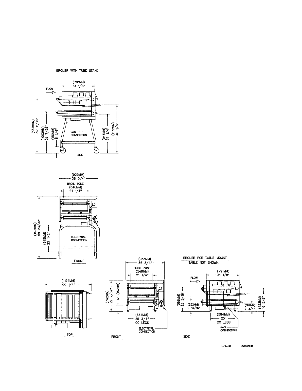
Model 1424/1450G SPECIFICATION DRAWINGS
DIMENSIONS INCH MM
Length 44 1/4 1124
Height 29 7/32 742
Width 36 3/4 933
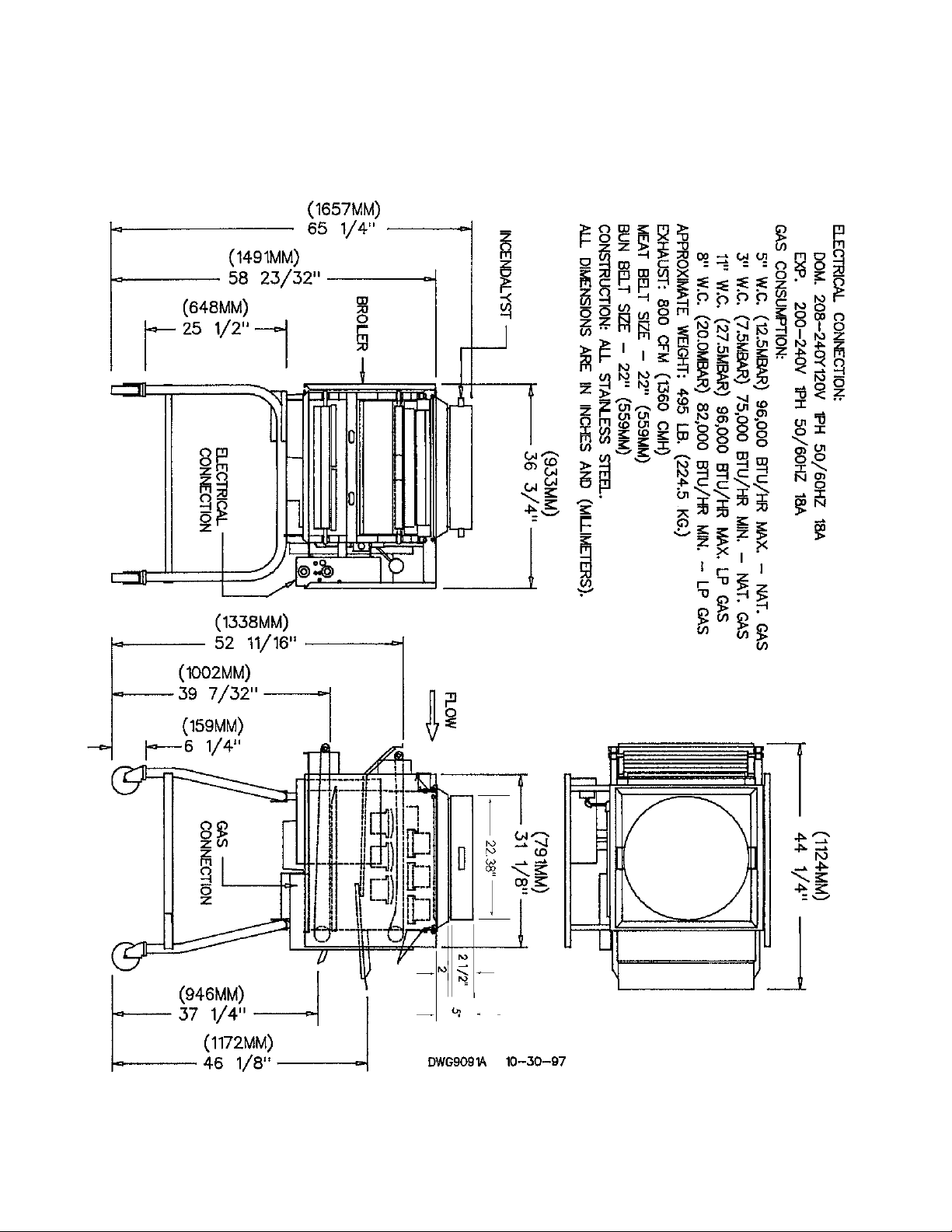
ENERGY - GAS MODELS
Gas Connection 3/4” N.P.T.
Electrical Connection (specify exact voltage)
Domestic 208-240Y120V 1Ø 50/60Hz 18A
Export 200-240V 1Ø 50/60Hz 18A
Avg. kW/hr 1.8
Natural Gas 3” W.C. 5” W.C.
BTU/hr 75,000 96,000
KCAL/hr 18,900 24,192
Liquid Propane 8” W.C. 11” W.C.
BTU/hr 82,000 96,000
KCAL/hr 20,664 24,192
WEIGHT LB KG
Shipping 525 240
EXHAUST CFM CMH
Typical 800 1360
NOTE - FOR ALTITUDE INSTALLATION ONLY: Equipment
installation at an altitude above 5,000 feet may require minor adjustments
depending upon the BTU content of incoming natural gas. Propane gas is
not recommended for units installed above 7,000 feet Electric is
recommended.
4
Model 1424/1450G with Incendalyst
SPECIFICATION DRAWINGS

5
B. INSTALLATION
PRE-INSTALLATION
Uncrate the broiler, and inspect for shipping damage. Contact the factory if there is obvious damage.
Remove the tape securing the machine parts, and install the parts in their proper location. Refer to the
Parts and Location section of this manual. If you find concealed damage to any part of this unit, contact
your freight carrier immediately. The factory warranty does not cover freight damage.
MOUNTING
If the broiler was shipped with a tubular stand, refer to separate tubular stand assembly instructions.
Note: The four legs of the broiler stand are equipped with casters. Always set the brakes on the
casters to prevent the broiler from shifting during operation or cleaning.
LEVELING
Make sure that the broiler is level. Factory stands are equipped with adjustable casters.
HOOD REQUIREMENTS
This appliance must be installed under a ventilation hood of adequate size and capacity:
Model CFM CMH
1424/1450 800 1360
The hood should be at least 6" (152MM) larger in all dimensions than the appliance top, and be 12" to
18" (305MM - 457MM) above the top. Do not obstruct the flow of combustion and ventilation air. An adequate air supply must be available for safe and proper operation.
Note: See the National Fire Prevention Association booklet on ventilation of cooking equipment.
Write to: NFPA, 470 Atlantic Ave., Boston, MA 02210. Local codes on venting must also be complied with.
CLEARANCE
For proper installation, the minimum clearance from combustible and non-combustible construction is 6"
(152MM) from the back and 6" (152MM) from the front of the machine. Keep appliance area free from
combustibles.
To facilitate disassembly and service of the unit a minimum of 24" (610MM) should be allowed on the
control panel (right) side of the broiler, as well as in front of the broiler.
GAS CONNECTION
At rated BTU capacity, the gas supply should deliver a pressure of at least 6" water column at the broiler
connection for natural gas, and 11" water column for propane gas. Incoming gas supply pressure must
not exceed 14" water column for either type of gas.
The appliance was shipped from the factory ready for gas supply hook-up to the shutoff valve under the
broiler. For disconnect, a manual valve must be located in the gas supply line upstream from the connecter.
If the machine is installed on a moveable stand; (1) the installation shall be made with a connector that
complies with the Standard for Connectors for Moveable Gas Appliances, ANSI Z21.69-1987, and
Addenda, Z21.6a-1989, and a quick disconnect device that complies with the Standard for QuickDisconnect Devices for Use With Gas Fuel, ANSI Z21.41-1989, and (2) adequate means must be provided to limit the movement of the appliance without depending on the connector and the quick-disconnect
device or its associated piping to limit the appliance movement. (See figures on page 6.)
Note: Appliance installation must conform with all local codes, or in the absence of local codes,
with the National Fuel Gas Code ANSI Z223.1-1988. Check all fittings for gas leaks, including
pilot tubing and inlet connections as soon as the appliance is connected to the gas supply.

6
Note: This appliance and its individual shutoff valve must be disconnected from the gas supply
piping system during any pressure testing of that system at test pressures in excess of 1/2 psig
(3.45 kPa).
Note: This appliance must be isolated from the gas supply piping system by closing its individual
manual shutoff valve during any pressure testing of the gas supply piping system at test pressures equal to or less than 1/2 psig (3.45 kPa).
In Canada, installation shall be in accordance with CAN/CGA-B149.1 Natural Gas or CAN/CGA-B149.2
Propane Gas, and local codes where applicable.
By public initiative, the State of California has adopted legislation (Proposition 65) which requires manufacturers of many types of products, including gas appliances, to warn consumers of their products that
contain chemicals or produce substances listed by the State of California to either cause cancer, birth
defects, or other reproductive harm.
WARNING: If not installed, operated, and maintained in accordance with the manufacturer's
instructions, this product could expose you to substances in fuel, or from fuel combustion which
can cause cancer, birth defects, or other reproductive harm.
ELECTRICAL CONNECTION
Power requirements are stated on the unit nameplate and must be connected accordingly. Before starting broiler, tighten all electrical connections in control box. An electrical diagram is located inside the control box.
Note: This appliance must be electrically grounded in accordance with local codes or in the
absence of local codes, the National Electrical Code, ANSI/NFPA No. 70-1990. In Canada, in
accordance with the Canadian Electrical Code CSA 22.1 part 1, or local codes.
WARNING: This appliance should be connected with a four-pronged grounding plug for
your protection against shock hazard. Be sure to plug directly into a properly grounded
four-prong receptacle. Do not cut or remove grounding prong from plug.
Note:
This appliance cannot be safely operated in the event of a power failure. No attempt
should be made to operate during a power failure. Disconnect power supply before servicing.
PRE-OPERATION CHECK
Be sure that all parts are installed in the proper location. Refer to OPERATION section for lighting procedure. Start broiler and test for proper operation.
7
INSTALLING GAS APPLIANCE CONNECTORS
AND FLEXIBLE GAS LINES CORRECTLY
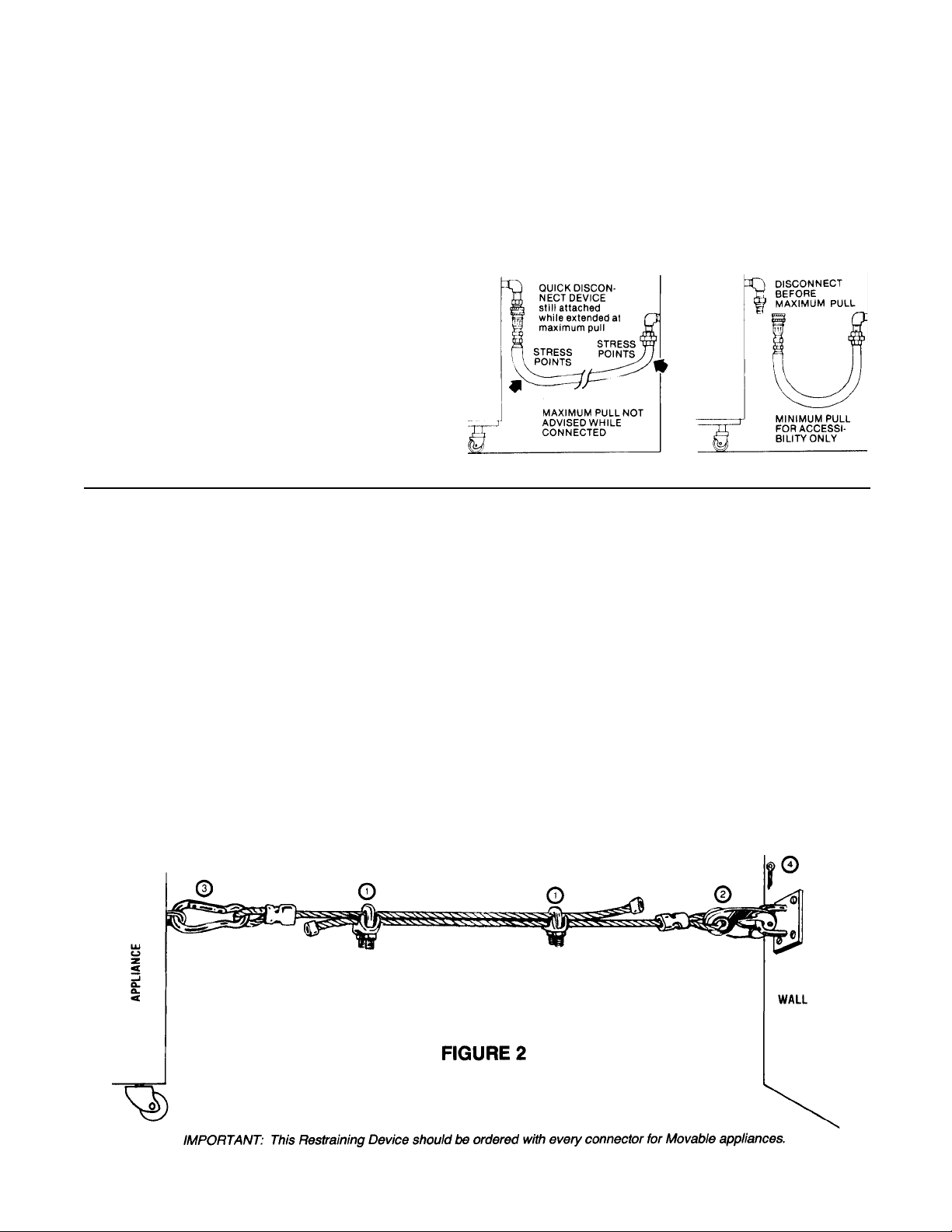
RESTRAINING DEVICE
INSTALLATION AND USE
This high strength restrainer is to be used with all moveable (castered) appliances. It fully complies with
American Gas Association requirements. References: Z21.69, Z83.11, and Z21.41 with current revisions.
Installation is quick and positive. In Canada, device is in accordance with CAN 1-6.9-M70 Quick
Disconnect Devices for use with gas fuel, and CAN 1-6.10-88 metal connectors for gas appliances.
Correct length for any appliance is simply a matter of loosening two adjuster clips (1) and re-tightening.
(3" to 6" shorter than appliance connector is desired length.)
Restrainer is made of heavy duty steel cable, with a strong scissor hood (2) at one end, and an equally
strong spring hook (3) at the other. Cotter pin (4) is supplied to secure the installation.
For safety in the kitchen area, and to insure maximum service life, it is vitally important to correctly
install connectors.
In order to avoid sharp kinks or excessive bends
that could have a damaging effect on the connector, it may be necessary to attach pipe elbows in
order to bring the connector into its proper plane.
For easy movement of the appliance, the connector should be installed with a "lazy" loop for minimum tension.
Note: Gas appliances should be disconnected
prior to maximum movement. (Minimal movement is possible to connect hose.)
WRONG
Avoid sharp bends and
kinks when pulling equipment away from wall.
RIGHT
Minimum pull of equipment is permissible for
accessibility to quick disconnect device.