

Nieco 1020G Parts List

AUTOMATIC
FOODSERVICE
EQUIPMENT
Automatic Cheese Melter
Model 820 & 1020 GAS
OWNER’S MANUAL
Sandwiches ◆Soups ◆Salads
IMPORTANT: RETAIN THIS MANUAL IN A SAFE PLACE FOR FUTURE REFERENCE.
Broiler area must be kept free of combustible materials, and the flow of combustion and
ventilation air must not be obstructed. Operating personnel must not perform any maintenance or repair functions. Contact your Nieco Authorized Dealer.
In a prominent location, post instructions to be followed in the event the user smells gas.
This information shall be obtained by consulting your local gas supplier.
FOR YOUR SAFETY:
Do not store or use gasoline or other flammable vapors or liquids in the
vicinity of this or any other appliance.
WARNING: Improper installation, adjustment, alteration, maintenance
can cause property damage, injury, or death. Read the installation,
operating and maintenance instructions thoroughly before installing
or servicing this equipment.

TABLE OF CONTENTS
General Information
..................................................................................................................................................................................................
3
Description
Machine Installation
................................................................................................................................................................................................
4
Pre-Installation
Mounting
Hood Requirements
Clearance
Gas Connection
Electrical Connection
Pre-Operation Check
Gas Connectors and Restraining Device
Operation
........................................................................................................................................................................................................................................
7
Step-by-step Lighting Procedure
Emergency Shutdown Procedure
Parts and Location
......................................................................................................................................................................................................
9
Exploded Drawings
Replacement Parts List
Cleaning Instructions
............................................................................................................................................................................................
13
Conveyor Belt Removal
Condensed Cleaning Instructions
Trouble Shooting Guide
..................................................................................................................................................................................
17
Specifications
......................................................................................................................................................................................................................
18
Wiring Diagram
..................................................................................................................................................................................................................
19
2
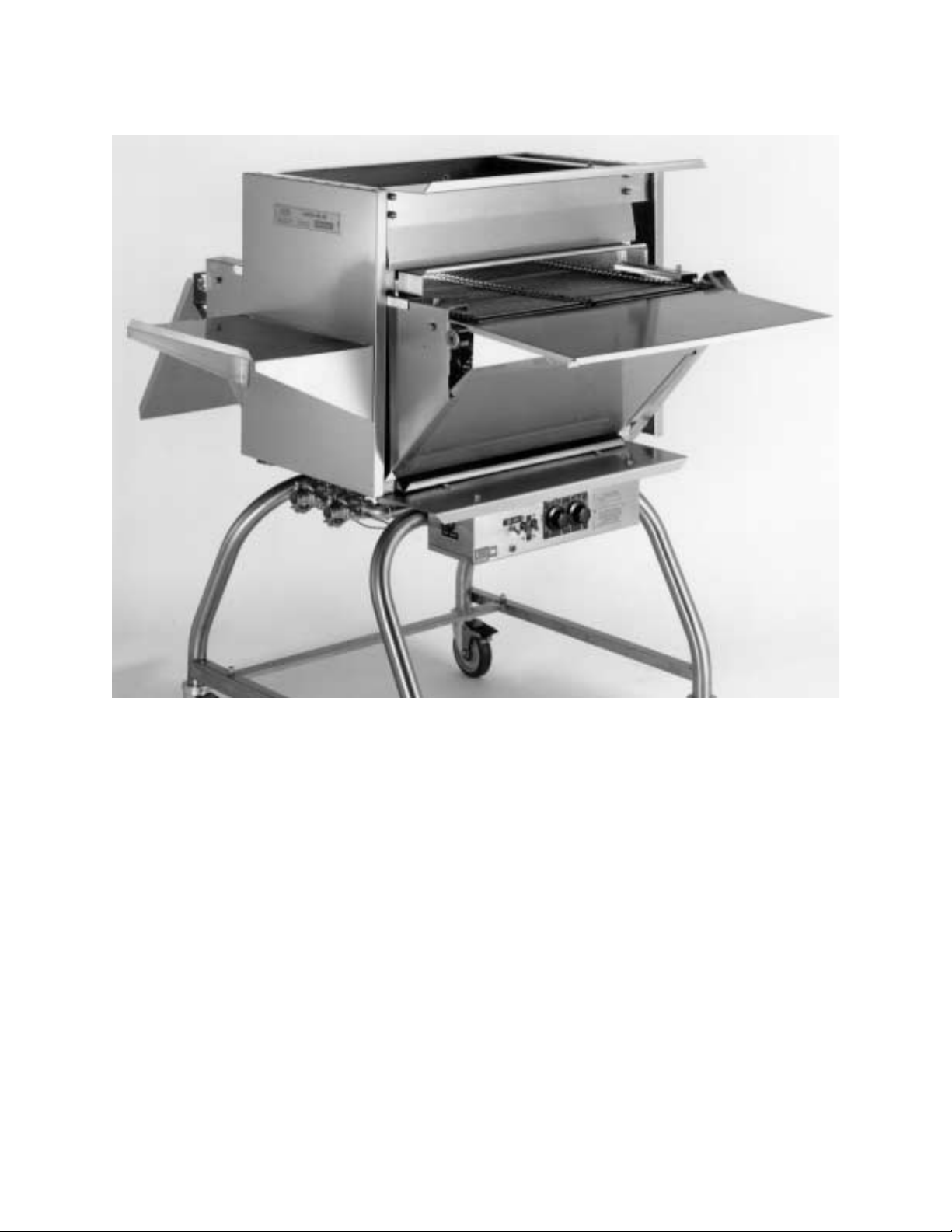
AUTOMATIC CHEESE MELTER
Model 820
DESCRIPTION
The Nieco Model 820 and 1020 Cheese Melter is a compact, self contained, flow
through unit that is designed to melt cheese and to toast buns. The unit employs dual
12" wide rod belts, or a single 24” wide belt that flow through the cheese melter in opposite directions between the three upper and one lower burner or four upper and two
lower burners in the Model 1020. Each belt is independently driven and controlled.
3

4
INSTALLATION
PRE-INSTALLATION
Uncrate the machine, and inspect for shipping damage. Contact the factory if there is
obvious damage. Remove the tape securing the machine parts, and install the parts in
their proper location. Refer to the Parts and Location section of this manual. If you find
concealed damage to any part of this unit, contact your freight carrier immediately. The
factory warranty does not cover freight damage.
MOUNTING
If the cheese melter was shipped with a tubular stand, refer to separate tubular stand
assembly instructions.
HOOD REQUIREMENTS
This appliance must be installed under a ventilation hood of adequate size and capacity
(approximately 600 CFM). The hood should be at least 6" larger in all dimensions than
the appliance top, and be 12" to 18" above the top. Do not obstruct the flow of combustion and ventilation air. An adequate air supply must be available for safe and proper
operation.
Note: See the National Fire Prevention Association booklet on ventilation of
cooking equipment. Write to: NFPA, 470 Atlantic Ave., Boston, MA 02210. Local
codes on venting must also be complied with.
CLEARANCE
For proper installation, the minimum clearance from combustible and non-combustible
construction is 6" from the back and 6" from the front of the machine. Keep appliance
area free from combustibles.
To facilitate disassembly and service of the unit a minimum of 24" should be allowed on
the control panel (right) side of the cheese melter, as well as on the feed and discharge
ends of the cheese melter.
GAS CONNECTION
At rated BTU capacity, the gas supply should deliver a pressure of at least 6" water column at the cheese melter connection for natural gas, and 11" water column for propane
gas. Incoming gas supply pressure must not exceed 14" water column for either type of
gas.
This appliance was shipped from the factory ready for gas supply hook-up to the shutoff
valve under the cheese melter. For disconnect, a manual valve must be located in the
gas supply line upstream from the connecter.
If the machine is installed on a moveable stand; (1) the installation shall be made with a
connector that complies with the Standard for Connectors for Moveable Gas
Appliances, ANSI Z21.69-1987, and Addenda, Z21.6a-1989, and a quick disconnect
device that complies with the Standard for Quick-Disconnect Devices for Use With Gas
Fuel, ANSI Z21.41-1989, and (2) adequate means must be provided to limit the movement of the appliance without depending on the connector and the quick-disconnect
device or its associated piping to limit the appliance movement. (See figures on
page 6.)

Note: Appliance installation must conform with all local codes, or in the absence
of local codes, with the National Fuel Gas Code ANSI Z223.1-1988. Check all fittings for gas leaks, including pilot tubing and inlet connections as soon as the
appliance is connected to the gas supply.
Note: This appliance and its individual shutoff valve must be disconnected from
the gas supply piping systems during any pressure testing of that system in
excess of 1/2 psig (3.45 kPa).
Note: This appliance must be isolated from the gas supply piping system by
closing its individual manual shutoff during any pressure testing of that system at
test pressures equal to or less than 1/2 psig (3.45) kPa).
In Canada, installation shall be in accordance with CAN/CGA-B149.1 Natural Gas or
CAN/CGA-B149.2 Propane Gas, and local codes where applicable.
By public initiative, the State of California has adopted legislation (Proposition 65) which
requires manufacturers of many types of products, including gas appliances, to warn
consumers of their products that contain chemicals or produce substances listed by the
State of California to either cause cancer, birth defects, or other reproductive harm.
WARNING: If not installed, operated, and maintained in accordance with the manufacturer's instructions, this product could expose you to substances in fuel, or
from fuel combustion which can cause cancer, birth defects, or other reproductive harm.
ELECTRICAL CONNECTION
Power requirements are stated on the unit nameplate and must be connected accordingly. Before starting cheese melter, tighten all electrical connections in control box.
Note: This appliance must be electrically grounded in accordance with local
codes or in the absence of local codes, the National Electrical Code, ANSI/NFPA
No. 70-1990. In Canada, in accordance with the Canadian Electrical Code CSA
22.1 part 1, or local codes.
WARNING: This appliance should be connected with a three-pronged
grounding plug for your protection against shock hazard. Be sure to plug
directly into a properly grounded three-prong receptacle. Do not cut or
remove grounding prong from plug.
Note:
This appliance cannot be safely operated in the event of a power failure.
No attempt should be made to operate during a power failure. Disconnect power
supply before servicing.
PRE-OPERATION CHECK
Be sure that all parts are installed in the proper location. Refer to OPERATION section
for lighting procedure. Start cheese melter and test for proper operation.
5
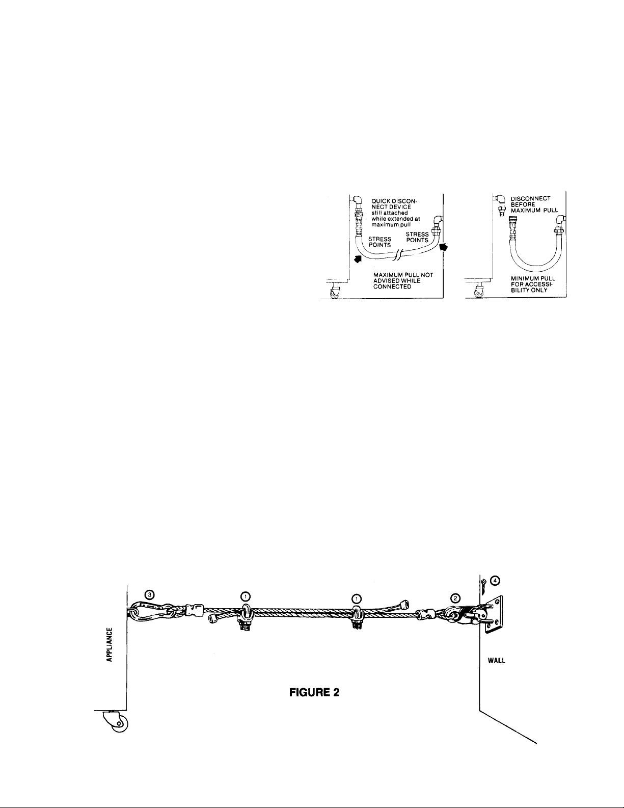
INSTALLING GAS APPLIANCE CONNECTORS
AND FLEXIBLE GAS LINES CORRECTLY
RESTRAINING DEVICE
INSTALLATION AND USE
This high strength restrainer is to be used with all moveable (castered) appliances. It
must fully comply with International Approval Services requirements. References:
Z21.69, Z83.11, and Z21.41 with current revisions. Installation is quick and positive. In
Canada, device is in accordance with CAN 1-6.9-M70 Quick Disconnect Devices for
use with gas fuel, and CAN 1-6.10-88 metal connectors for gas appliances.
Correct length for any appliance is simply a matter of loosening two adjuster clips (1)
and re-tightening. (3" to 6" shorter than appliance connector is desired length.)
Restrainer is made of heavy duty steel cable, with a strong scissor hood (2) at one end,
and an equally strong spring hook (3) at the other. Cotter pin (4) is supplied to secure
the installation.
For safety in the kitchen area, and to
insure maximum service life, it is vitally
important to correctly install connectors.
In order to avoid sharp kinks or excessive
bends that could have a damaging effect
on the connector, it may be necessary to
attach pipe elbows in order to bring the
connector into its proper plane. For easy
movement of the appliance, the connector
should be installed with a "lazy" loop for
minimum tension.
Note: Gas appliances should be disconnected prior to maximum movement. (Minimal movement is possible
to connect hose.)
WRONG
Avoid sharp bends and
kinks when pulling equipment away from wall.
RIGHT
Minimum pull of equipment is permissible for
accessibility to quick
disconnect devic
e.
6
IMPORTANT: This Reastraining Device should be odered with every connector for Moveable appliances
OPERATION
In the following section, a brief step-by-step sequence of lighting and operating procedure is given. For reference, a condensed lighting procedure is located on the front of
the control panel.
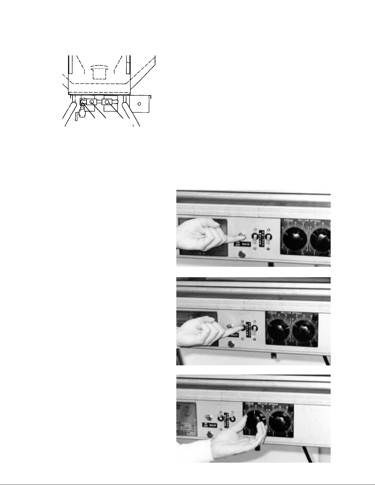
Step-By-Step Lighting Procedure
1. Turn on Main Power Switch.
2. Turn on Motor Power Switches.
3. Set Motor Speed Controls to desired
cook time.
Note: Your cheesemelter is equipped
with a constant burning pilot. After
the initial lighting, the cheesemelter
is shut down and re-lit simply by
turning the main power siwtch on
and off.
1. Main Gas Valve controls the flow of
incoming gas. Valve is open when handle is
in-line with the piping, and closed when it is
perpendicular.
2. Solenoid Valve automatically shuts off
gas supply if power fails.
3. Pushbutton Gas Valves (2) control the
flow of gas to the upper and lower burners.
3a is for the lower burner, and 3b is for the
upper burners.
7
1 2 3a 3b
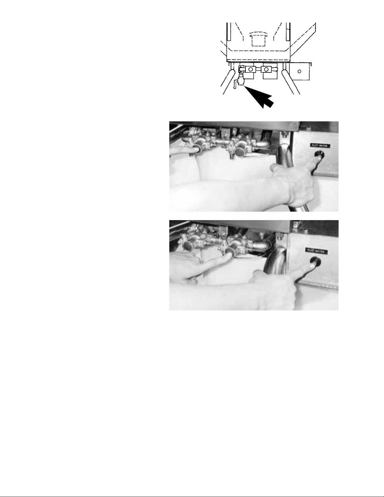
4. Open Main Gas Valve located on the
lower left side of the machine. Valve is open
when the handle is in-line with the valve.
5. Light the Lower Pilot Burner by
holding in the red button marked bottom pilot and simultaneously pressing the red Pilot Ignition button. After
pilot ignites, continue to hold the bottom pilot button in for about 20 seconds to insure pilot remains lit.
6. Repeat step 5 with the Upper
Pilot Burner. After 20 seconds
release pilot button and the main
burners will ignite.
If the pilot lights are burning:
1. Turn on the exhaust hood above the cheesemelter.
2. Turn on the Main Power Switch. At this time, the main burners should ignite.
3. Turn on the Motor Switches, and set the cook times with the Motor Speed
Control Knobs.
If the pilot lights are not lit then follow the Step-byStep Lighting Procedure starting on
page 7 of this manual.
8
 Loading...