


kio
istruzioni e avvertenze per l’installatore
Instructions and warnings for the fitter
Instructions et recommandations pour l’installation
Anweisungen und hinweise für den installateur
Instrucciones j advertencias para el instalador
Instrukcja dla instalatora
Key-operated selector switch
with cord-type release


kio
Warnings
This manual has been especially written for use by qualified installation
technicians. No information given in this manual can be considered as
being of interest to end users. Read these instructions carefully before
proceeding with the installation, as they provide important information
regarding safety, installation, use and maintenance.
Any use or operation not explicitly provided for in these instructions is not
permitted. Improper use may cause damage and personal injury.
KIO is not suitable for use in potentially explosive atmospheres.
page
6 Testing 5
7 Maintenance 5
8 Disposal 6
9 Technical features 6
GB
3
Table of contents: page
1 Description 4
2 Dimensions 4
3 Fixing instructions 4
4 Electrical connection 5
5 Manual manoeuvres 5

4
1. Turn the key 90° in the required direction; Fig. 3
2. Open the release handle 90°; Fig. 4
3. Unscrew the protection panel screw and remove it; Fig. 5
4. Remove the protection panel counter spring; Fig. 6
5. Place the switch against the wall and mark the screw hole positions;
6. Drill four holes and fix the switch to the wall using the 4 screws
and suitable dowels; Fig. 7
7. Pass the steel wire as far as the release system leaving 20mm of
wire outside the sheath;
8. Remove the cover very carefully (A) and move the cursor to the
position shown in the illustration, and unscrew the grub screw;
Fig. 8
9. Insert the steel wire block it in position with the grub screw;
SCREW VERY TIGHTLY; Fig. 8b
10. Adjust the wire tension keeping in mind that the automatism will
result unblocked in the present position;
11. Replace the cover in position as in point 8;
12. Insert the spring in its housing and replace the protection guard
(B). Fixing it in position with the screws Fig. 9
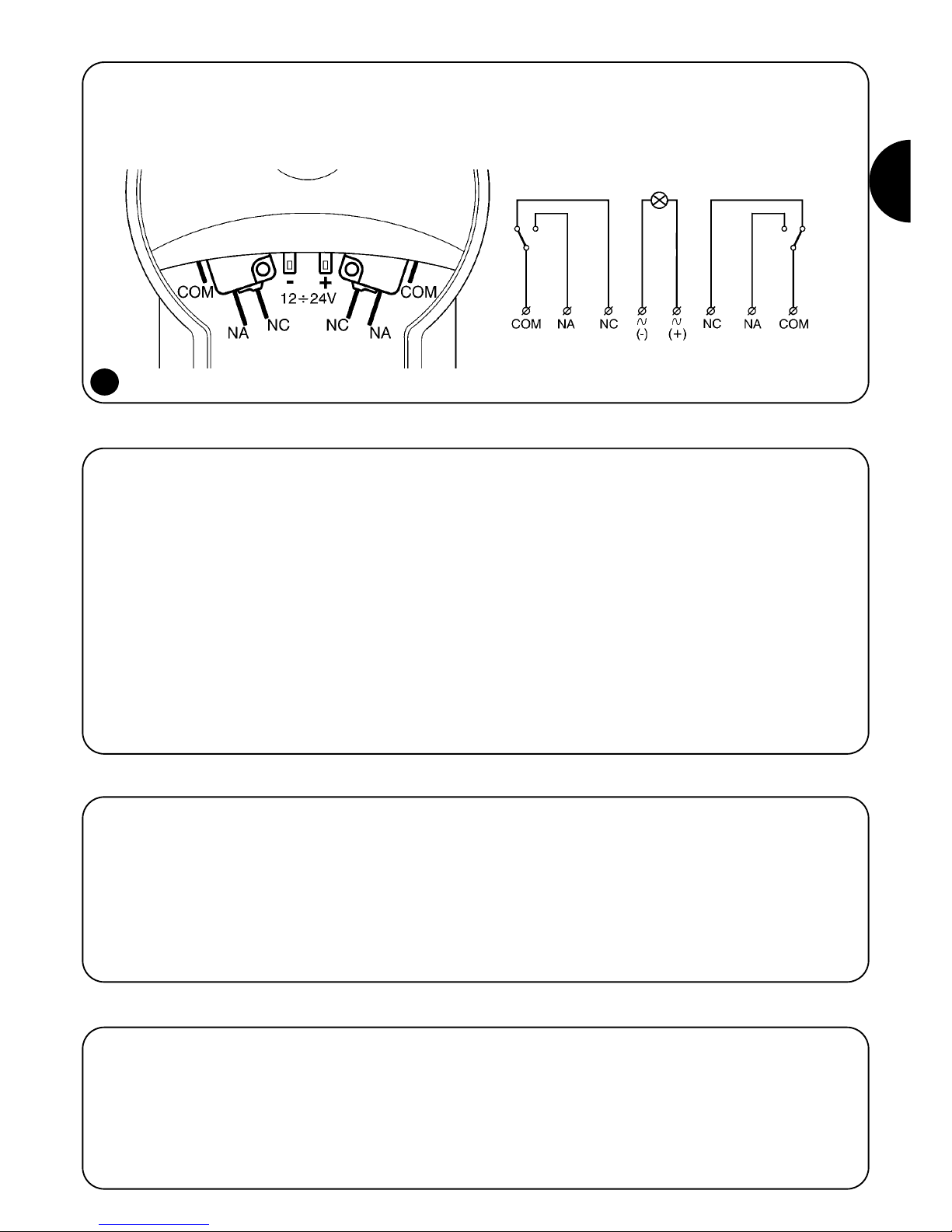
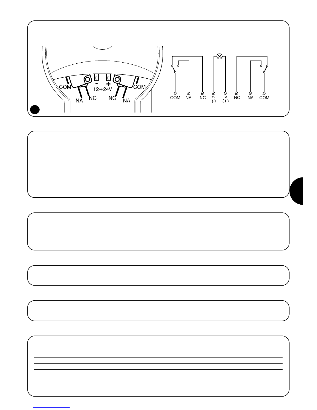
1) Description
KIO can be operated using a key switch with courtesy light or a
release switch. When the key is turned from vertical psition about
30°, two contacts are available: one in clockwise direction, and the
other in the opposite direction. When the key is turned further (in
either direction) the handle will open, and the release system will
function.
2) Dimensions
3) Fixing instructions
1
2
Release Release
Op Cl

GB
5
Use the contacts available for your equipment control. Never try to
command the motor directly. Fig. 10
4) Electrical connection
To release the gearmotor proceed as follows:
1. Manual operation must be performed when the gate is closed.
2. Turn the key completely using the finger to guide the release
handle; Fig. 11
3. Open the release handle 90° Fig. 12. In this case there should
be sufficient cable run to release the RONDO automatism. However, if the automatism requires a longer run, proceed as follows;
4.
With the handle open, pull the knob back towards yourself; Fig. 13
5. Turn it in a clockwise direction until it is blocked. Fig. 14
6. Open or close the gate manually;
7. To block the speed reducer, turn the knob in an anticlockwise
direction until it is blocked.
8. Re-insert the knob in the handle.
9. Close the handle with slight pressure. The handle can be closed
even with the motor released.
5) Manual manoeuvres
10
OPEN
COURTESY
LIGHT
CLOSE
To test the KIO follow this procedure:
•Make sure that the fusible elements are in good condition.
• Check that the lock is not rusted and that no friction exists when
the key is turned.
•Check that the release manoeuvre is performed easily.
•Check that there are no rusted parts inside the selector switch.
• Check that all electrical connections are in good condition.
• Check that all screwed connections are well tightened..
• Check correct contact operation.
6) Testing
KIO does not require any special maintenance, apart from a regular
scheduled maintenance control at least every six months to check
condition as described above (presence of damp, rust, etc) followed
by the standard test procedure.
7) Maintenance

6
KIO is composed of several different types of material some of which
can be recycled. Request information on product recycling or disposal methods according to local current laws and regulations.
8) Disposal
9) Technical features
Type : Key-operated selector switch with cord-type release
Courtesy light supply : Between 12V and 36Vdc, 12V and 28Vac
Protection class : IP55
Working temperature : Between -20 and +50°C (without ice forming)
Maximum contact voltage : 50Vac - Vdc
Maximum contact current : 1 A
Lock Combinations : 250.000
Nice S.p.a. reserves the right to make changes to its products at any time as it deems necessary.

kio
pag.
6 Collaudo 9
7 Manutenzione 9
8 Smaltimento 10
9 Caratteristiche tecniche 10
Indice: pag.
1 Descrizione del prodotto 8
2 Dimensioni d’ingombro 8
3 Fissaggio 8
4 Collegamenti elettrici 9
5 Manovra manuale 9
Avvertenze
Il presente manuale è destinato solamente al personale tecnico qualificato per l’installazione. Nessuna informazione contenuta nel presente
fascicolo può essere considerata d’interesse per l’utilizzatore finale.
E’ necessario leggere attentamente le istruzioni prima di procedere all’installazione, in quanto forniscono importanti indicazioni riguardanti la
sicurezza, l’installazione, l’uso e la manutenzione.
Tutto quello che non è espressamente previsto in queste istruzioni non è
permesso. L’uso improprio potrebbe essere fonte di danni e situazioni di
pericolo.
KIO non è adatto all’uso in atmosfera potenzialmente esplosiva.
I
7

8
1. Ruotare la chiave di 90° nel senso desiderato; Fig. 3
2. Aprire di 90° la maniglia di sblocco; Fig. 4
3. Svitare la vite fissa carter e toglierlo; Fig. 5
4. Togliere la molla spingi carter; Fig. 6
5. Appoggiare sulla parete il selettore e segnare la posizione dei
fori;
6. Eseguire quattro fori e fissare tramite 4 viti con relativi tasselli il
selettore alla parete; Fig. 7
7. Far arrivare allo sblocco il cavo d’acciaio lasciandolo sporgere di
20mm dalla guaina;
8. Togliere con delicatezza il coperchio (A) e portare il cursore in
posizione indicata in figura e svitare il grano; Fig. 8
9. Inserire il cordino d’acciaio bloccandolo con il grano; SERRARE
A FONDO; Fig. 8b
10. Registrare la tensione del cavo, tenendo presente che in questa
posizione, l’automatismo risulterà sbloccato;
11. Re inserire il coperchio tolto al punto 7;
12. Inserire la molla nell’apposita sede e posizionare il carter (B) fissandolo con la vite (C). Fig. 9
1) Descrizione del prodotto
KIO ha la funzione sia di selettore a chiave con luce di cortesia, che
di sblocco manuale. Ruotando la chiave di circa 30° dalla posizione
verticale, avremo a disposizione due contatti: uno in senso orario e
uno antiorario. Continuando la rotazione della chiave (in entrambi i
sensi), la maniglia si aprirà e si potrà effettuare la manovra di sblocco.
La corsa massima del cursore all’interno della maniglia è di 60mm.
2) Dimensioni d’ingombro
3) Fissaggio
1
2
Sblocco Sblocco
Ap Ch
I
9
Utilizzare i contatti disponibili per comandare la vostra apparecchiatura. Non utilizzare mai per comandare direttamente il motore. Fig. 10
4) Collegamenti elettrici
Per sbloccare il motoriduttore occorre:
1. La manovra manuale va eseguita a portone fermo
2. Ruotare completamente la chiave accompagnando con un dito
l’apertura della maniglia di sblocco; Fig. 11
3. Aprire di 90° la maniglia di sblocco Fig. 12. In questo caso si
avrà ottenuto una corsa della fune sufficiente a sbloccare l’automatismo RONDO. Se invece, l’automatismo da sbloccare,
necessita di una corsa maggiore, agire come segue;
4. A maniglia aperta, tirare verso di se il pomello; Fig. 13
5. Ruotarlo in senso orario fino al bloccaggio; Fig. 14
6. Aprire o chiudere manualmente il portone;
7. Per bloccare il motoriduttore, ruotare il pomello in senso antiorario fino bloccaggio;
8. Re inserire il pomello dentro la maniglia;
9. Chiudere la maniglia con una leggera pressione. E’ possibile
richiudere la maniglia anche a motore sbloccato
5) Manovra manuale
Per il collaudo del KIO eseguire questa procedura
•Verificare che le fusioni siano i buono stato.
•Verificare che la serratura non sia ossidata e la rotazione della chia-
ve non presenti punti d’attrito.
•Verificare che la manovra di sblocco avvenga in maniera agevole.
•Verificare che all’interno del selettore non ci siano parti ossidate.
•Verificare che i collegamenti elettrici siano in buono stato.
•Verificare che i collegamenti a vite siano ben stretti.
•Verificare il corretto funzionamento dei contatti.
6) Collaudo
10
APRE
LUCE DI
CORTESIA
CHIUDE
KIO non necessita di accorgimenti particolari, ma è necessaria una
manutenzione programmata almeno ogni 6 mesi nella quale venga
verificato lo stato dello stesso (presenza di umidità, ossidi, ecc.) e
rieseguita la procedura di collaudo.
7) Manutenzione

10
KIO è costituito da varie tipologie di materiali, alcuni possono essere
riciclati. Informatevi sui sistemi di riciclaggio o smaltimento del prodotto attenendosi alle norme vigenti a livello locale.
8) Smaltimento
9) Caratteristiche tecniche
Tipologia : Selettore a chiave con sblocco a fune
Alimentazione luce di cortesia : Da 12V a 36Vdc, da 12V a 28Vac
Grado di protezione : IP55
Temperatura di funzionamento : Da –20 a +50°C (senza formazione di ghiaccio)
Tensione massima contatti : 50Vac – Vdc
Corrente massima contatti : 1A
Combinazioni serratura : 250.000
Nice S.p.a. si riserva il diritto di apportare modifiche ai prodotti in qualsiasi momento riterrà necessario

kio
page
6 Essai de fonctionnement 13
7 Maintenance 13
8 Mise au rebut 14
9 Caractéristiques techniques 14
Table des matières: page
1 Description 12
2 Dimensions d’encombrement 12
3 Fixation 12
4 Branchements électriques 13
5 Manœuvre manuelle 13
Recommandations importantes
Ce manuel est destiné exclusivement au personnel technique qualifié
pour l’installation. Aucune information contenue dans ce fascicule ne
peut être considérée comme intéressante pour l’utilisateur final. Il est
nécessaire de lire attentivement les instructions avant de procéder à
l’installation, étant donné qu’elles fournissent d’importantes indications
au sujet de la sécurité, de l’installation, de l’utilisation et de la maintenance.
Tout ce qui n’est pas expressément prévu dans ces instructions, est
interdit. L’utilisation impropre pourrait être la cause d’endommagements
et de situations dangereuses.
KIO n’est pas approprié à l’utilisation en atmosphère potentiellement
explosive
F
11

12
1. Tourner la clé de 90° dans le sens désiré; Fig. 3
2. Abaisser le corps de la poignée de débrayage à 90°; Fig. 4
3. Dévisser la vis de fixation du carter et l’enlever; Fig. 5
4. Enlever le ressort de blocage du carter; Fig. 6
5. Poser le sélecteur sur le mur et marquer la position des trous;
6. Percer quatre trous, appliquer les chevilles et fixer le sélecteur au
mur à l’aide des 4 vis; Fig. 7
7. Faire arriver le câble en acier au débrayage en laissant dépasser
20mm de la gaine;
8. Enlever délicatement le couvercle (A) et mettre le curseur dans la
position indiquée dans la figure puis dévisser le goujon; Fig. 8
9. Insérer le cordon en acier et le bloquant avec le goujon, SER-
RER À FOND; Fig. 8b
10. Régler la tension du câble en tenant compte du fait que dans
cette position l’automatisme sera débrayé;
11. Remettre en place le couvercle enlevé au point 8;
12. Introduire le ressort dans son logement et positionner le carter
(B) en le fixant avec la vis (C). Fig. 9
1) Description
KIO a la fonction à la fois de sélecteur à clé avec éclairage de fonctionnement, et de débrayage manuel. La rotation de la clé d’environ
30° par rapport à la position verticale permet d’obtenir deux
contacts: un dans le sens des aiguilles d’une montre, l’autre dans le
sens contraire. En continuant la rotation de la clé (dans les deux
sens) le corps de la poignée s’abaisse et on pourra effectuer la
manœuvre de débrayage.
La course maximum du curseur à l’intérieur de la poignée est de
60mm.
2) Dimensions d’encombrement
3) Fixation
1
2
Débrayage Débrayage
Ou Fe

F
13
Utiliser les contacts disponibles pour commander votre appareil.
Ne jamais utiliser les contacts pour commander directement le
moteur. Fig. 10
4) Branchements électriques
Pour débrayér l’opérateur il faut:
1. La manœuvre manuelle doit être effectuée avec le tablier du
rideau métallique ou de la porte à l’arrêt.
2. Tourner la clé à fond en accompagnant d'un doigt l'ouverture de
la poignée de débrayage; Fig. 11
3. Abaisser le corps de la poignée de débrayage à 90° Fig. 12.
Dans ce cas, on aura obtenu une course du câble suffisante
pour débrayer l’automatisme RONDO. Si par contre, l’automatisme à débrayer a besoin d’une course plus longue, agir de la
façon suivante;
4. Avec le corps de la poignée abaissée, tirer vers soi la poignée
proprement dite; Fig. 13
5. La tourner dans le sens des aiguilles d’une montre jusqu’au blocage; Fig. 14
6. Ouvrir ou fermer manuellement le rideau métallique ou la porte;
7. Pour bloquer l’opérateur, tourner la poignée dans le sens
contraire aux aiguilles d’une montre jusqu’au blocage;
8. Enfoncer la poignée à l’intérieur de son logement;
9. Fermer le corps de la poignée avec une légère pression; on peut
le refermer même avec le moteur débrayé.
5) Manœuvre manuelle
10
OUVRE
ÉCLAIRAGE
AUTOMATIQUE
FERME
Pour l’essai du sélecteur KIO, procéder de la façon suivante:
• Vérifier que les parties moulées sont en bon état.
• Vérifier que la serrure n’est pas oxydée et que la rotation de la clé
ne présente pas de points de frottement.
• Vérifier que la manœuvre de débrayage s’effectue facilement.
• Vérifier qu’il n’y a pas de parties oxydées à l’intérieur du sélecteur.
• Vérifier que les connexions électriques sont en bon état.
• Vérifier que les assemblages par vis sont bien serrés.
• Vérifier le fonctionnement correct des contacts.
6) Essai de fonctionnement
KIO ne nécessite pas d’entretien particulier mais il faut procéder toutefois tous les 6 mois à une maintenance programmée durant laquelle il faudra vérifier la présence d’humidité, d’oxydations, etc. et effectuer de nouveau l’essai de fonctionnement.
7) Maintenance

14
KIO est constitué de différents types de matériaux dont certains peuvent être recyclés. Informez-vous sur les systèmes de recyclage ou
de mise au rebut du produit en respectant les normes locales en
vigueur.
8) Mise au rebut
9) Caractéristiques techniques
Typologie : Sélecteur à clé avec débrayage par câble
Alimentation éclairage automatique : De 12V à 36Vcc, de 12V à 28Vca
Indice de protection : IP55
Température de fonctionnement : De -20 à +50°C (sans formation de glace)
Tension maximum contacts : 50Vca - Vcc
Courant maximum contacts : 1A
Combinaisons serrure : 250 000
Nice S.p.a. se réserve le droit d’apporter des modifications aux produits à tout moment si elle le jugera nécessaire.

kio
S.
6 Endprüfung 17
7 Wartung 17
8 Entsorgung 18
9 Technische Merkmale 18
Inhaltsverzeichnis S.
1 Beschreibung 16
2 Gesamtabmessungen 16
3 Befestigung 16
4 Elektrische anschlüsse 17
5 Handbedienung 17
Hinweise
Die vorliegende Anleitung ist nur für technisches Personal bestimmt, das
für die Installation qualifiziert ist. Keine im vorliegenden Heft enthaltene
Information kann als interessant für den Endbenutzer betrachtet werden.
Die Anweisungen vor der Installation genau lesen, da sie wichtige Hinweise liefern, was Sicherheit, Installation, Bedienung und Wartung
betrifft.
Alles nicht ausdrücklich in diesen Anweisungen vorgesehene ist unzulässig. Ein unsachgemäßer Gebrauch könnte Schäden und Gefahren
verursachen.
KIO ist für den Gebrauch in potentieller EX-Atmosphäre ungeeignet.
D
15

16
1. Den Schlüssel um 90° in der gewünschten Richtung drehen;
Abb. 3
2. Den Entriegelungsgriff auf 90° öffnen; Abb. 4
3. Die Schraube, mit der das Gehäuse befestigt ist, losschrauben
und das Gehäuse entfernen; Abb. 5
4. Die Gehäuse-Schiebefeder entfernen; Abb. 6
5. Den Schlüsseltaster an die Wand legen und die Bohrungen aufzeichnen;
6. Vier Bohrungen machen und den Schlüsseltaster mit 4 Schrauben und den jeweiligen Dübeln an der Wand befestigen; Abb. 7
7. Das Stahlseil zur Entriegelung führen und 20mm aus dem Mantel herausragen lassen;
8. Den Deckel (A) behutsam entfernen und den Schieber in die auf
der Abbildung gezeigte Stellung bringen und die Stiftschraube
losschrauben; Abb. 8
9. Das Stahlseil einfügen mit der Stiftschraube blockieren; FEST
ANZIEHEN; Abb. 8b
10. Die Seilspannung registrieren, dabei berücksichtigen, dass der
Automatismus in dieser Stellung entriegelt ist;
11. Den in Punkt 8 entfernten Deckel wieder anbringen;
12. Die Feder in ihren Sitz einfügen und das Gehäuse (B) anbringen
und mit der Schraube (C) befestigen. Abb. 9
1) Beschreibung
KIO dient sowohl als Schlüsseltaster mit zusätzlicher Beleuchtung
als auch als manuelle Entriegelung. Wenn man den Schlüssel um ca.
30° aus der vertikalen Stellung dreht, wird man zwei Kontakte zur
Verfügung haben: einen im Uhrzeigersinn, den anderen gegen den
Uhrzeigersinn. Wenn der Schlüssel weiter gedreht wird (in eine der
beiden Richtungen) wird sich der Griff öffnen und man kann die Entriegelung ausführen.
Der maximale Lauf des Schiebers im Griff ist 60mm.
2) Gesamtabmessungen
3) Befestigung
1
2
Entriegelung Entriegelung
Öf Sc

D
17
Die zur Verfügung stehenden Kontakte zum Steuern Ihrer Apparatur
verwenden. Nie den Motor direkt damit steuern. Abb. 10
4) Elektrische anschlüsse
Entriegelung des Getriebemotors:
1. Die Handbedienung muss mit stillstehendem Tor erfolgen.
2. Den Schlüssel ganz drehen, dabei die Öffnung des Entriegelungsgriffs mit einem Finger unterstützen - Abb. 11
3. Den Entriegelungsgriff auf 90° öffnen Abb. 12. In diesem Fall
wird das Stahlseil so weit gleiten, dass der Automatismus RONDO entriegelt wird. Wenn der Automatismus dagegen mehr Seil
benötigt, um entriegelt zu werden, ist wie folgt vorzugehen;
4. Mit geöffnetem Griff, den Knauf zu sich ziehen; Abb. 13
5. Im Uhrzeigersinn drehen, bis er blockiert ist; Abb. 14
6. Das Tor von Hand öffnen bzw. schließen;
7. Zum Blockieren des Getriebemotors, den Knauf gegen den Uhrzeigersinn drehen, bis er blockiert ist;
8. Den Knauf wieder in den Griff einfügen;
9. Den Griff mit leichtem Druck schließen. Der Griff kann auch mit
entriegeltem Motor geschlossen werden.
5) Handbedienung
10
ÖFFNET
ZUSÄTZLICHE
BELEUCHTUNG
SCHLIEßT
Zur Endprüfung des KIO ist wie folgt vorzugehen:
• Prüfen, dass die Teile aus Aludruckguss in gutem Zustand sind.
• Prüfen, dass der Schlüsseltaster keine Roststellen aufweist und
dass die Schlüsseldrehung ohne Reibungen erfolgt.
• Prüfen, dass der Entriegelungsvorgang leicht erfolgt.
• Prüfen, dass sich keine verrosteten Teile im Schlüsseltaster befin-
den.
• Prüfen, dass die elektrischen Verbindungen in gutem Zustand
sind.
• Prüfen, dass die Schraubverbindungen fest angezogen sind.
• Die korrekte Funktionsweise der Kontakte überprüfen.
6) Endprüfung
KIO bedarf keiner besonderen Wartungsarbeiten, trotzdem ist mindestens alle 6 Monate eine programmierte Wartung erforderlich, mit
Überprüfung des Zustandes der Vorrichtung (Feuchtigkeit, Roststellen, usw.), gefolgt von der erneuten Durchführung der Endprüfung.
7) Wartung

18
KIO besteht aus verschiedenen Werkstoffen, von denen einige recycled werden können. Informieren Sie sich, wie Sie das Produkt unter
Einhaltung der örtlich gültigen Vorschriften recyclen oder entsorgen
können.
8) Entsorgung
9) Technische Merkmale
Typik : Schlüsseltaster mit Seilentriegelung
Versorgung, zusätzliche Beleuchtung : von 12V bis 36Vdc, von 12V bis 28Vac
Schutzart : IP55
Betriebstemperatur : von -20 bis +50°C (ohne Eisbildung)
Höchstspannung, Kontakte : 50Vac - Vdc
Höchststrom, Kontakte : 1A
Schlosskombinationen : 250.000
Nice S.p.a behält sich das Recht vor, jederzeit Änderungen am Produkt anzubringen.
kio
pág.
6 Ensayo 21
7 Mantenimiento 21
8 Desguace 22
9 Características técnicas 22
Índice: pág.
1 Descripción 20
2 Medidas exteriores máximas 20
3 Fijación 20
4 Conexiones eléctricas 21
5 Maniobra manual 21
Advertencias
Este manual está destinado sólo al personal técnico cualificado para la
instalación. Ninguna información contenida en este manual puede ser
considerada de interés para el usuario final. Es necesario leer con atención las instrucciones antes de comenzar con la instalación, porque
estas ofrecen indicaciones importantes acerca de la seguridad, instalación, uso y mantenimiento.
Está prohibido todo aquello que no esté expresamente previsto en estas
instrucciones. El empleo inadecuado puede ser causa de averías y
situaciones peligrosas.
KIO no es adecuado para su uso en atmósfera con riesgo de explosión.
E
19

20
1. Gire la llave 90° hacia la dirección deseada; Fig. 3
2. Abra 90° la manilla de desbloqueo; Fig. 4
3. Desenrosque el tornillo que fija el cárter y quítelo; Fig. 5
4. Quite el muelle de empuje del cárter; Fig. 6
5. Apoye sobre la pared el selector y marque la posición de los
agujeros;
6. Realice cuatro taladros y fije el selector a la pared con 4 tornillos
y sus tacos respectivos; Fig. 7
7. Haga llegar al dispositivo de desbloqueo el cable de acero y
déjelo que sobresalga 20mm de la vaina;
8. Quite con cuidado la tapa (A), coloque el cursor en la posición
indicada en la figura y desenrosque el tornillo sin cabeza; Fig. 8
9. Introduzca el cable de acero bloquéelo con el tornillo sin cabeza; APRIETE HASTA EL FONDO; Fig. 8b
10. Regule la tensión del cable, teniendo en cuenta que en esta
posición el automatismo estará desbloqueado;
11. Monte de nuevo la tapa que ha quitado en el punto 7;
12. Introduzca el muelle en su alojamiento y coloque el cárter (B)
fijándolo con el tornillo (C); Fig. 9
1) Descripción
KIO cumple la función tanto de selector de llave con luz de cortesía
como de desbloqueo manual. Girando la llave alrededor de 30° desde la posición vertical, tendremos a disposición dos contactos: uno
en sentido horario y el otro en sentido antihorario. Si se sigue girando la llave (en ambos sentidos), la manilla se abrirá y se podrá efectuar la maniobra de desbloqueo.
La carrera máxima del cursor en el interior de la manilla es de 60mm.
2) Medidas exteriores máximas
3) Fijación
1
2
Desbloqueo Desbloqueo
Ab Ce

E
21
Utilice los contactos disponibles para accionar el equipo. Nunca utilice los contactos para accionar directamente el motor. Fig. 10
4) Conexiones eléctricas
Para desbloquear el motorreductor, siga estos pasos:
1. La maniobra manual se debe realizar con el cerramiento detenido.
2. Gire completamente la llave acompañando conun dedo la apertura de la manilla de desbloqueo; Fig. 11
3. Abra 90° la manilla de desbloqueo Fig. 12. En este caso se habrá
obtenido una carrera del cable suficiente para desbloquear el
automatismo RONDO. Si por el contrario, para desbloquear el
automatismo se requiere una carrera mayor, siga estos pasos;
4. Con la manilla abierta, tire del pomo hacia Ud.; Fig. 13
5. Gírelo en sentido horario hasta que se bloquee; Fig. 14
6. Abra o cierre manualmente el cerramiento;
7. Para bloquear el motorreductor, gire el pomo en sentido antihorario hasta que se bloquee;
8. Introduzca de nuevo el pomo adentro de la manilla;
9. Cierre la manilla presionando ligeramente. Es posible cerrar la
manilla incluso con el motor desbloqueado.
5) Maniobra manual
10
ABRIR
LUZ DE
CORTESÍA
CERRAR
Para el ensayo de KIO siga este procedimiento
• Controle que todos los componentes metálicos estén en buenas
condiciones.
• Controle que la cerradura no esté oxidada y que la llave gire sin
presentar puntos de fricción.
• Controle que la maniobra de desbloqueo se pueda realizar fácil-
mente.
• Controle que en el interior del selector no haya piezas oxidadas.
• Controle que las conexiones eléctricas estén en buenas condicio-
nes.
• Controle que las conexiones roscadas estén bien apretadas.
• Controle que los contactos funcionen correctamente.
6) Ensayo
KIO no requiere cuidados especiales, pero es necesario realizar un
mantenimiento programado por lo menos cada 6 meses para verificar el estado de los componentes (presencia de humedad, oxidación, etc.) y volver a realizar el ensayo.
7) Mantenimiento
22
KIO está formado de distintos tipos de materiales, algunos de estos
pueden reciclarse. Infórmese sobre los sistemas de reciclado o desguace del producto respetando las normas locales vigentes en
materia.
8) Desguace
9) Características técnicas
Tipo : Selector de llave con desbloqueo por tirador
Alimentación de la luz de cortesía : De 12V a 36Vdc, de 12V a 28Vac
Grado de protección : IP55
Temperatura de funcionamiento : De -20 a +50°C (sin formación de hielo)
Tensión máxima en los contactos : 50Vac - Vdc
Corriente máxima en los contactos : 1A
Combinaciones cerradura : 250.000
Nice S.p.a. se reserva el derecho de modificar los productos cuando lo considere necesario.
kio
pag.
6 Test odbiorczy 25
7 Czynności konserwacyjne 25
8 Utylizacja 25
9 Dane techniczne 25
Spis: pag.
1 Opis 24
2 Wymiary Gabarytowe 24
3 Mocowanie 24
4 Połączenia Elektryczne 25
5 Ruch Ręczny 25
Ostrzeżenie
Niniejsza instrukcja przeznaczona jest wyłącznie dla technika
instalatora z odpowiednimi kwalifikacjami. Żadna z informacji
zawartych w niniejszej instrukcji nie służy użytkownikowi. Przed
przystąpieniem do instalowania automatyki należy uważnie
przeczytać całą instrukcję, ponieważ dostarcza ona ważnych
informacji związanych z bezpieczeństwem, instalacją, użytkowaniem
i czynnościami konserwacyjnymi.
Inne czynności poza tymi zawartymi w niniejszej instrukcji nie są
dozwolone. Niewłaściwe użytkowanie może być źródłem uszkodzeń i
niebezpiecznych sytuacji.
Siłownik RONDO nie jest przeznaczony do użytku w środowisku
zagrożonym eksplozją.
PL
23

24
1. Przekręcić kluczem o 90 w żądanym kierunku; Rys. 3
2. Przekręcić uchwyt wysprzęglenia o 90; Rys. 4
3. Odkręcić i wyciągnąć wkręt mocujący osłonę; Rys. 5
4. Odczepić sprężynę naciskającą osłonę; Rys. 6
5. Dosunąć do ściany selektor i zaznaczyć pozycję otworów;
6. Wywiercić cztery otwory i przymocować selektor do ściany 4
wkrętami, pamiętając o założeniu podkładek; Rys. 7
7. Podłączyć do wysprzęglenia linkę stalową, której 20 mm ma
wystawać z powłoki;
8. Delikatnie odczepić pokrywkę (A) i ustawić wodzik na pozycji
wskazanej na rysunku, po czym odkręcić śrubkę; Rys. 8
9. Założyć stalową linkę i zablokować śrubką; DOKR CIĆ DO
OPORU; Rys. 8b
10. Zarejestrować natężenie linki mając na uwadze, że w tej
pozycji automatyka jest odblokowana;
11. Założyć pokrywkę, o której mowa w punkcie 7;
12. Założyć na miejsce sprężynkę i ustawić osłonę (B) I przykręcić
wkrętem (C). Rys. 9
1) Opis
KIO służy jako selektor kluczowy ze światełkiem nocnym i jako
ręczne wysprzęglenie. Przekręcając kluczem o kąt około 30 od
pozycji poziomej będziemy mieć do dyspozycji dwa wyłączniki:
jeden w kierunku zegarowym i drugi w kierunku przeciwnym.
Kontynuując przekręcanie klucza (w dowolnym kierunku) uchwyt
otworzymy i będzie można wykonać ruch wysprzęglenia.
Maksymalna długość ruchu wodzika wewnątrz uchwytu wynosi
60mm.
2) Wymiary Gabarytowe
1
2
Wysprzęglenie Wysprzęglenie
Ot Za
PL25PL
Do sterowania waszego urządzenia należy zastosować
odpowiednie kontakty. Nigdy nie stosować ich do bezpośredniego
sterowania silnika. Rys. 10
4) Połączenia Elektryczne
1. Ruch ręczny należy wykonać przy bramie zamkniętej.
2. Całkowicie przekręcić kluczem uchwyt wysprzęgający
pomagając sobie palcem; Rys. 11.
3. Otworzyć do 90 uchwyt wysprzęglenia. Rys. 12 W tym
wypadku uzyska się wystarczającą długość ruchu linki do
odblokowania automatyki RONDO. Gdy jednak do
odblokowania automatyki wymagana jest dłuższa długość
ruchu należy postąpić następująco;
4. Gdy uchwyt jest otwarty pociągnąć pokrętło w kierunku do
siebie; Rys. 13
5. Przekręcić do oporu w kierunku zegarowym; Rys. 14
6. Otworzyć i zamknąć ręcznie bramę;
7. Aby zablokować siłownik przekręcić pokrętłem do oporu w
kierunku przeciwnym;
8. Ponownie założyć pokrętło do uchwytu;
9. Zamknąć uchwyt lekkim naciśnięciem. Można zamknąć
uchwyt nawet, gdy silnik jest odblokowany.
5) Ruch Ręczny
10
OTWIERA
ŚWIATEłKO
OSTRZEGAWCZE
ZAMYKA
Test odbiorczy KIO wykonać według poniższej procedury:
• Sprawdzić stan odlewow.
• Sprawdzić czy zamek nie jest zardzewiały i czy klucz przekręca
się swobodnie.
• Sprawdzić czy ruch wysprzęglania odbywa się swobodnie.
• Sprawdzić czy wnętrze wyłącznika nie jest zabrudzone osadem.
• Sprawdzić stan połączeń elektrycznych.
• Sprawdzić stan połączeń śrubowych.
• Sprawdzić funkcjonowanie złączy.
6) Test odbiorczy
KIO nie wymaga specjalnej uwagi, ale należy wykonywać
czynności konserwacyjne zaprogramowane co najmniej co 6
miesięcy należy wówczas sprawdzić jego stan (obecność
wilgotności, osadów, itp.) i należy powtórzyć próby ostateczne.
7) Czynności konserwacyjne
KIO zbudowany jest z wielu rodzajów surowców, niektóre z nich
można przerobić. Zapoznać się z obowiązującymi miejscowymi
normami zbytu produktu.
8) Utylizacja
9) Dane techniczne
Typologia : Wyłącznik na klucz z linowym wysprzęglaniem
Zasilenia do światełka nocnego : Od 12V do 36Vdc, od 12V do 28Vac
Stopień zabezpieczenia : IP 55
Temperatura funkcjonowania : Od -20 do + 55°C (bez zamrażania)
Maksymalne napięcie w kontaktach : 50Vac - Vdc
Maksymalny prąd w kontaktach : 1A
Kody zamknięcia : 250.000
Nice zastrzega sobie prawo do wprowadzenia zmian w produktach w każdym momencie, kiedy będzie uważała za niezbędne.

6
9
3 4 5
12
7
8b
13
8
11
14
A
B
C

15
KIO
rif. mod. art.
1 BMG0796 34567
2 BMG0798 34567
3 BMM0797 34567
4 PPD0805 4540
5 PPD0802 4540
6 PPD0824 4540
7 PPD0823 4540
8 PPD0799 4540
9 PPD0803 4540
10 PPD0800 4540
11 PPD0801 4540
12 PPD0804 4540
13 PMD0806 4610
14 PMD0807 4610
15 V4x10-B 5102
16 V4.2x9 5101
17 MO-0922 2640
18 V3.5x25 5101
19 V3.5x13 5101
20 R05 5120
21 PMCS42 4630
22 G5x6 5123
23 MO-0923 2640
24 PMD0925 4610
25 PMCSE8 4630
26 MICROI-C 1617
27 GOR-E 5501
28 GOR-A 5501
29 149-A 8001
30 CM-H 1630
31 MO-0924 2640
32 MPTASS-A 5101

Dichiarazione CE di conformità / EC declaration of conformity
Amministratore delegato
(General Manager)
Lauro Buoro
Numero / Number: 169/KIO Data / Date: 04/2003 Revisione / Revision: 0
Il sottoscritto Lauro Buoro, Amministratore Delegato, dichiara che il prodotto:
The undersigned Lauro Buoro, General Manager, declares that the product:
Nome produttore / Producer name: NICE S.p.a.
Indirizzo / Address: Via Pezza Alta 13, 31046 Z.I. Rustignè - ODERZO - ITALY
Tipo / Type: selettore a chiave con sblocco a fune / Control Unit for 1 motor 24Vd.c. for sectional doors
Modello / Model: KIO
Accessori / Accessories: Nessun accesssorio / No accessory
Risulta conforme a quanto previsto dalle seguenti direttive comunitarie / Complies with the following community directives
Riferimento n° Titolo
Reference n° Title
89/336/CEE DIRETTIVA 89/336/CEE DEL CONSIGLIO del 3 maggio 1989, per il riavvicinamento delle legislazioni degli Stati membri
relative alla compatibilità elettromagnetica.
Council Directive 89/336/EEC of 3 May 1989 on the approximation of the laws of the Member States relating to
electromagnetic compatibility
Oderzo, 4 Aprile 20003
IST RN 4865 REV. 00
www.niceforyou.com
Nice S.p.a. Oderzo TV Italia
Via Pezza Alta, 13 Z.I. Rustignè
Tel. +39.0422.85.38.38
Fax +39.0422.85.35.85
info@niceforyou.com
Nice Padova Sarmeola I
Tel. +39.049.89.78.93.2
Fax +39.049.89.73.85.2
info.pd@niceforyou.com
Nice Roma I
Tel. +39.06.72.67.17.61
Fax +39.06.72.67.55.20
info.roma@niceforyou.com
Nice Belgium
Leuven (Heverlee) B
Tel. +32.(0)16.38.69.00
Fax +32.(0)16.38.69.01
info@nicebelgium.be
Nice España Madrid E
Tel. +34.9.16.16.33.00
Fax +34.9.16.16.30.10
kamarautom@nexo.es
Nice France Buchelay F
Tel. +33.(0)1.30.33.95.95
Fax +33.(0)1.30.33.95.96
info@nicefrance.fr
Nice France Sud Aubagne F
Tel. +33.(0)4.42.62.42.52
Fax +33.(0)4.42.62.42.50
info.marseille@nicefrance.fr
Nice Rhône-Alpes
Decines Charpieu F
Tel. +33.(0)4.78.26.56.53
Fax +33.(0)4.78.26.57.53
info.lyon@nicefrance.fr
Nice Polska Pruszków PL
Tel. +48.22.728.33.22
Fax +48.22.728.25.10
nice@nice.com.pl
 Loading...