

Nice HYKE HK7224, HYKE HK7024HS, HYKE HK7024, HYKE HK7224HS Instructions And Warnings For Installation And Use
EN - Instructions and warnings for installation and use
IT - Istruzioni ed avvertenze per l’installazione e l’uso
FR - Instructions et avertissements pour l’installation et l’utilisation
ES - Instrucciones y advertencias para la instalación y el uso
DE - Installierungs-und Gebrauchsanleitungen und Hinweise
PL -Instrukcjeiostrzeżeniadoinstalacjiiużytkowania
NL - Aanwijzingen en aanbevelingen voor installatie en gebruik
Swing gate opener
HYKE
HK7024
HK7224
HK7024HS
HK7224HS

1 2
3
4
320 mm
210 mm 290 mm

1
3 2
5
76
0
150 175 200 225 250 275 300 325 350 375 400 425 450 475
50
B
A
100
150
200
250
300
350
400
450
90°-95°
95°-100°
100°-105°
105°-110°
90°-95°
95°-105°
8

1 2
a
b
3
9
b
a
9
b
a
a
b
x 4
c
a
4
5
1
2
3
4
90°
90°
10
OK
OK
7
6
8

9
1 2
a
b
3
10
b
x 4
c
a
4
5
8
b
a
10
1
2
3
13
11
6
OK
OK
7

1
2
90°
3
90°
12-A
90°
2
1
3
12-B
3
NO
2
NO
4
OK
3
NO
2
NO
11
1
4
OK
3
NO
2
NO
3
2
54

FLASH ELS S.C.A. OPEN CLOSEBLUEBUS
TX
24V 4W
RX
P. P.
NC NO CC NO NC
STOP
P. P. STOP
+–
24 Vcc
13
1
2
14
1 2
5
1
2
3 4

6
1
2
87
15
1 3
5
1
2
2
4
16
17
1
2
76
OPEN STOP CLOSE
L1 L2 L3 L4 L5 L6 L7 L8
1
2
1
2
18
1 3
5
1
2
2
2
1
4
19
1 2

1
2
20
1
4
1
2
3
2
21
1 3
5
1
2
2
4
6
2
1
3
7

EN
English – 1
ENGLISH
1.1 - Safety warnings
• IMPORTANT! – This manual contains important instructions and
warnings regarding safety. Incorrect installation may cause serious injury.
Before commencing work, all sections of the manual must be read carefully.
If in any doubt, suspend installation and call the Nice Support Service for
clarification.
• IMPORTANT! – This manual contains important instructions. Keep it
for future maintenance work and disposal of the product.
• IMPORTANT! – Under the latest European legislation, automatic door
and gate installations must be compliant with the standards specified
in Directive 2006/42/EC (formerly 98/37/EC) (the Machinery Directive)
and the standards EN 12445, EN 12453, EN 12635 and EN 13241-1 in
particular, which enable conformity of the automated functionality to
be de clared. In the light of the above, all work involving installation,
connection, testing and maintenance of the product must be carried
out exclusively by qualified and competent technicians!
1.2 - Warnings for installation
• Before commencing the installation, check if the product is suitable for the de sired
type of use (see “Usage limitation” paragraph 3.2 and the “Product te chnical specifications”). If it is not suitable, DO NOT continue with the installation.
• The contents of this manual refer to a standard system as described in fig. 3.
• All installation and maintenance work must be carried out with the
au to mation system disconnected from the electricity supply. If the
power discon nection device cannot be seen from where the automation system is po sitioned, then before starting work a notice must be attached to the
disconnection device bearing the words “CAUTION! MAINTENANCE IN PROGRESS”.
• The Control unit must be connected to an electricity supply line equipped
with protective earthing.
• Handle the product with care during installation, taking care to avoid crushing, denting or dropping it, or contact with liquids of any kind. Keep the
product away from sources of heat and naked flames. Failure to observe the
above can damage the product, and increase the risk of danger or malfunction. Should this occur, suspend installation work immediately and contact
the Nice Support Service.
• Do not modify any part of the product. Prohibited modifications can only
lead to malfunctions. The manufacturer declines all responsibility for damage
re sulting from unauthorized changes made to the product.
• If the gate or door being automated has a pedestrian gate, then the system
must include a control device that will inhibit the operation of the motor when
the pedestrian gate is open.
• The product’s packaging material must be disposed of in full compliance with
local regulations.
1.3 - Warnings for use
• The product is not intended for use by persons, including children, with limited physical, sensory or mental capacities, or who lack experience or knowledge, unless supervised or trained in the use of the product by a person
responsible for their safety.
• Any children near the automation system must be kept under supervision to
ensure that they do not play with it.
• Do not allow children to play with the fixed control devices. Keep remote
control devices out of the reach of children.
WARNINGS AND GENERAL PRECAUTIONS
1
Contents
Images
1 - WARNINGS AND GENERAL PRECAUTIONS ...................................... 1
1.1 - Safety warnings ..................................................................................... 1
1.2 - Installation warnings .............................................................................. 1
1.3 - Operation warnings ............................................................................... 1
2 - PRODUCT DESCRIPTION AND INTENDED USE ................................ 1
3 - INSTALLATION ...................................................................................... 2
3.1 - Preliminary installation checks ............................................................... 2
3.2 - Application limits ................................................................................... 2
3.3 - Preliminary installation set-up work ........................................................ 2
3.4 - Installation of gearmotor mod. HK7024 - HK7224 - HK7024HS -
HK7224HS .................................................................................................... 2
3.5 - Mechanical limit switch adjustment ........................................................ 3
3.6 - Manually releasing and locking the gearmotor ....................................... 4
4 - ELECTRICAL CONNECTIONS .............................................................. 4
4.1 - Electrical connections of gearmotor with control unit mod. HK7024 -
HK7024HS .................................................................................................... 4
4.2 - Connection of gearmotor without control unit mod. HK7224 -
HK7224HS .................................................................................................... 4
4.3 - Connection of other devices .................................................................. 4
4.4 - Routing connected devices ................................................................... 5
4.5 - Initial start-up and connection check ..................................................... 5
4.6 - Learning of the connected devices ........................................................ 5
4.7 - Mechanical limit switch positioning learning ........................................... 5
4.8 - Gate leaf movement check .................................................................... 6
5 – TESTING AND COMMISSIONING ........................................................ 6
5.1 - Testing .................................................................................................. 6
5.2 - Commissioning ..................................................................................... 6
6 – CONTROL PANEL PROGRAMMING .................................................... 7
6.1 - Level 1 programming (ON-OFF functions) .............................................. 7
6.2 - Level 2 programming (adjustable parameters) ....................................... 8
6.3 - Special functions ................................................................................... 9
6.4 - Deleting the memory ............................................................................. 9
7 – TROUBLESHOOTING... (troubleshooting guide) ............................... 9
8 - FURTHER INFORMATION................................................................... 11
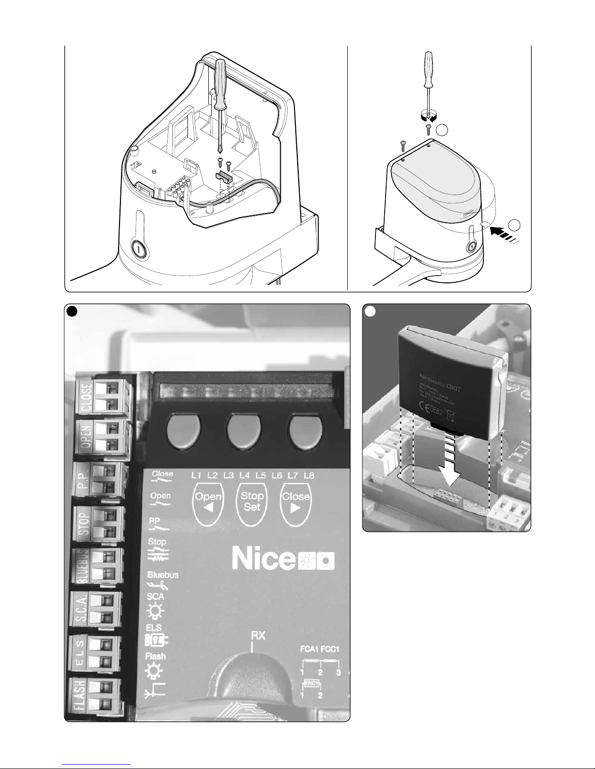
8.1 - Connecting a radio receiver ................................................................. 11
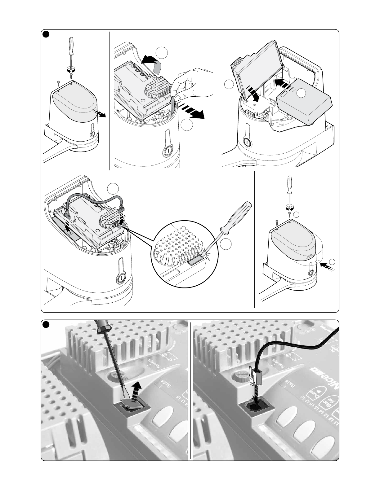
8.2 - Connecting and installing the buffer battery mod. PS124 .................... 11
8.3 - Connecting the Oview programmer ..................................................... 11
8.4 - Connecting the solar power system Solemyo ...................................... 11
8.5 - Connecting the external release system Kio ........................................ 11
9 - PRODUCT MAINTENANCE ................................................................ 12
PRODUCT DISPOSAL .............................................................................. 12
Product lifetime ........................................................................................ 12
TECHNICAL SPECIFICATIONS OF PRODUCT ....................................... 13
CE DECLARATION OF CONFORMITY .................................................... 14
APPENDIX .................................................................................................... I
Instructions and warnings for the user ........................................................... II
The devices comprising this product are designed to automate a gate or door
with one or two leaves. IMPORTANT! – Any other use apart from that
described herein, including in different environmental conditions from
those described in this manual is to be considered improper use and is
not permitted!
The principal component of the automation system comprises one or two electric gearmotors (according to the number of leaves to be automated), each
equipped with a direct current motor and epicyclic reduction gear. One of the
gearmotors (mod. HK7024 - HK7024HS) has a control unit that controls its
operation. The Control unit consists of a board with a radio receiver for receiving the commands sent by the transmitter.
The control unit is designed for connection to several devices belonging to the
Opera system, the Bluebus system and the Solemyo solar powered system,
see chapter 8 - Further information
If it is mains powered, it can house a back-up battery (mod. PS124, optional
accessory) which in the event of a power cut (electricity black-out) guarantees
that the automated device will perform certain manoeuvres in the hours that follow.
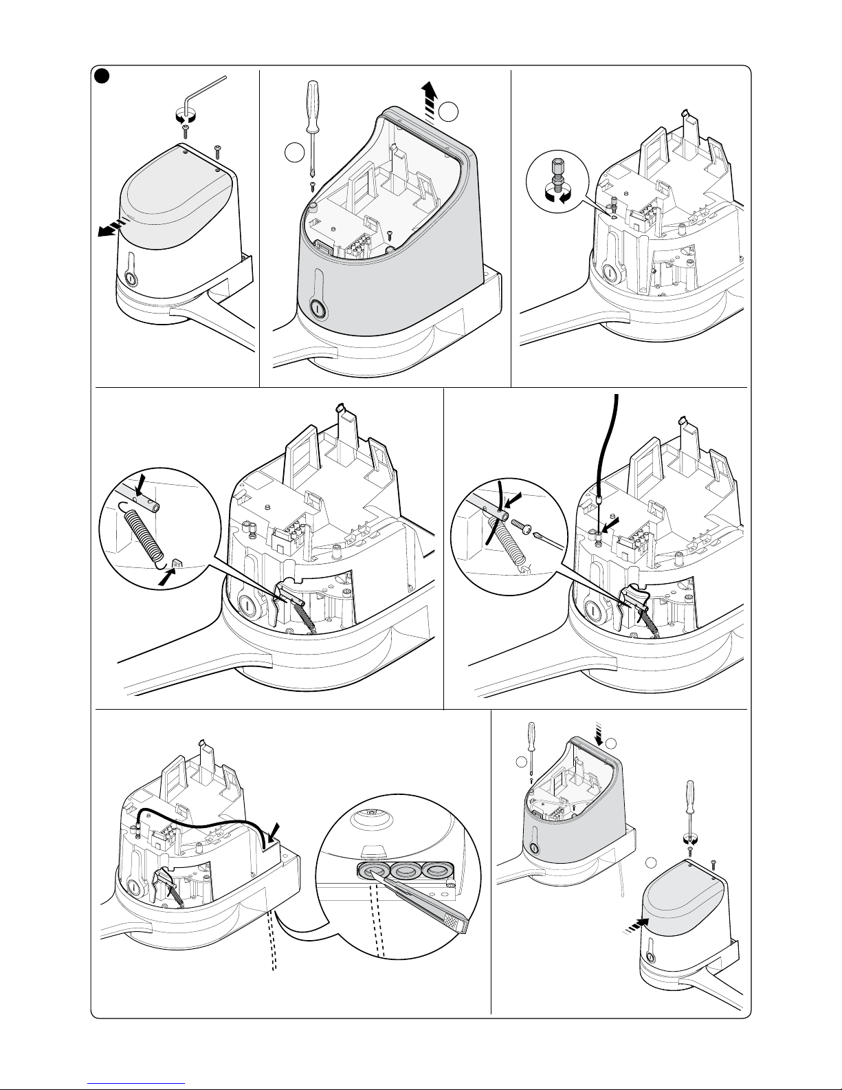
In the event of a power cut, the gate leaves can be moved by releasing the
gearmotor with the dedicated key; to perform the manoeuvre manually please
see chapter 3.6.
Other available accessories include the receivers designed with “SM” connectors (SMXI, OXI, etc.), see chapter 8 - Further information.
PRODUCT DESCRIPTION AND
INTENDED USE
2
Instructions translated from Italian

EN
2 – English
set at the LONG length. In these conditions, the maximum leaf opening can
reach 110°.
350
150
100
1,822,533,5
200
250
300
GRAPH 1
For full length
arm
For shortened
arm
WIDTH (m.)
WEIGHT (kg.)
3.3 - Preliminary installation set-up work
Fig. 3 provides an example of an automation system, produced using Nice
components (some components may not be present in the kit):
a - Gearmotor with control unit model HK7024 - HK7024HS
b - Gearmotor without control unit model HK7224 - HK7224HS
c - Flashing light
d - Pair of photocells model MOFB
e - Digital keypad (mod. MOTB) - Transponder badge reader (mod. MOMB) –
Key-operated selector switch (mod. MOSE)
f - Pair of posts for photocells
g - Mechanical stop on closing
h - Electric lock
These parts are positioned according to a typical standard layout. With reference to fig. 3, locate the approximate position for installation of each component envisaged in the system. Important – Before installation, prepare the
electric cables required for the system, with reference to fig. 4 and “Tab l e 1
- Technical specifications of electric cables”.
Caution! – When laying the ducting for routing the electrical cables, also take
into account that due to possible deposits of water in the routing ducts, the
connection pipelines must not create condensate in the control unit, with consequent damage to the electronic circuits.
3.4 - Installation of gearmotor mod. HK7024 - HK7224 - HK7024HS
- HK7224HS
WARNINGS
• Incorrect installation may cause se rious phy sical inj ury to those
working on or using the system.
• Before starting automation assembly, make the preliminary checks
as described in paragraphs 3.1 and 3.2.
Before starting installation, determine the length of the gearmotor arm with reference to paragraph 3.4.1.
3.4.1 - Determining the length of the gearmotor arm
01. Assemble the components of the motor arm as shown in fig. 5.
02. Establish the position of the gearmotor in the VERTICAL direction:
on the column, trace a horizontal line at the same height as the designated
position of the fixing bracket for the arm on the leaf after installation (fig. 6).
03. Establish the position of the gearmotor in the HORIZONTAL direc-
tion (position A):
3.1 - Pre-installation checks
Before going ahead with the installation, check the integrity of the product
components, and ensure the model chosen is suitable for its intended use and
for the environment in which it is to be installed.
• Check that all the material to be used is in excellent condition and suitable for
its intended use.
• Check that the ground-mounted mechanical stops (not supplied), are present both when opening and closing the automation system.
• Check that the mechanical structure of the gate is suitable for the installation
of automation and compliant with locally applicable regulations (if necessary,
refer to the label on the gate). This product cannot be used to automate a
gate which is not already in good, safe working order, neither can it fix faults
caused by incorrect installation or poor maintenance of the gate.
• Check that the operating conditions of the devices are compatible with the
usage limitation declared (see paragraph 3.2).
• Move the gate leaves manually in both directions and ensure that the resistance to movement is constant at all points of travel (there should not be any
points where more force or less is required).
• Bring the gate leaves manually into a position at random, then let go and
check that they remain stationary.
• Check that the gearmotor fixing zone is compatible with its overall dimensions (fig. 1).
• Check that the place where the gearmotor is to be installed allows enough
space for its arm to execute its full range of movement.
• Check that there is sufficient room around the gearmotor for it to be released
manually when required.
• Ensure that the surfaces on which the various devices are to be installed are
strong and capable of ensuring a firm hold.
• Ensure that each device is installed in a position which is protected and does
not expose it to accidental impacts.
• Ensure that all the electrical cables to be used are the type listed in Table 1.
3.2 - Application limits
Before installing the gearmotor, ensure that the specifications meet the
requirements in terms of application limits as stated below and within the limits
as specified in “Product Technical Specifications”.
With the LONG motor arm:
- maximum leaf width: 3.50 m (= maximum leaf weight: 200 kg)
With the SHORT motor arm:
- maximum leaf width: 3.00 m (= maximum leaf weight: 180 kg)
HS VERSION:
With motor arm in FULL and REDUCED length:
- maximum leaf width: 3.00 m (= maximum leaf weight: 180 kg)
• Checks to perform: note on Graph 1 alongside, the weight and width of the
leaf; trace two lines from this point and check that these intersect within one
of the two grey areas of the graph. Caution! - If the lines intersect in the white
area, this product cannot be used to automate the gate.
• To enable installation of the gearmotor, the minimum column width must be
210 mm.
• The arm fixing bracket must be located in a resistant area of the leaf (for
example the frame), to guarantee a solid and safe fixture;
• Check position “E” (fig. 2):
- If position “E” is between 300 mm (minimum) and 650 mm (maximum),
the gearmotor arm must be set at the SHORT length. In these conditions,
the maximum leaf opening can reach 90°.
- If position “E” is equal to or over 650 mm, the gearmotor arm must be
INSTALLATION
3
TABLE 1 - Technical specifications of electric cables (fig. 4)
Connection Cable type Maximum admissible length
A: Cable CONTROL UNIT POWER SUPPLY 1 Cable 3 x 1,5 mm
2
30 m (note 1)
B: ELECTRIC LOCK Cable 1 Cable 2 x 1 mm
2
6 m
C: BLUEBUS DEVICE cable 1 Cable 2 x 0,5 mm
2
20 m (note 2)
D: KEY-OPERATED SELECTOR SWITCH cable 2 Cables 2 x 0,5 mm
2
(note 3) 50 m
E: GEARMOTOR POWER SUPPLY Cable
ENCODER CONNECTION cable
1 Cable 3 x 1,5 mm
2
(note 4)
1 Cable 2 x 1 mm2 (note 4)
10 m
10 m
F: FLASHING LIGHT with aerial cable 1 Cable 2 x 0,5 mm
2
1 RG58 type shielded cable
20 m
20 m (less than 5 m recommended)
Note 1 – If the power cable exceeds a length of 30 m, use a cable with a larger section (3x2.5 mm2); in this case earthing is required in the vicinity of the automation.
Note 2 – If the Bluebus cable exceeds a length of 20 m, up to a maximum of 40 m, use a cable with a larger section (2 x 1 mm
2
).
Note 3 – These 2 cables may be replaced with a single cable of 4 x 0,5 mm
2
.
Note 4 – These cables may be replaced with a single cable of 5 x 1,5 mm
2
.
CAUTION! – The cables used must be suited to the type of environment of the installation site.
 Loading...