

Nice HK7024, HYKE, HK7224, HK7024HS, HK7224HS Instructions And Warnings For Installation And Use

Nice
HYKE
HK7024
HK7224
HK7024HS
HK7224HS
Swing gate opener
EN - Instructions and warnings for installation and use

ENGLISH
Translation of the original instructions in full
CONTENTS
1
1 GENERAL SAFETY WARNINGS AND PRECAUTIONS
1.1 GENERAL WARNINGS
a
PRECAUTIONS
WARNING! Important safety instructions. Observe
all the instructions as improper installation may
cause serious damages.
GENERAL SAFETY WARNINGS AND
1 GENERAL SAFETY WARNINGS AND PRECAUTIONS . . . . . 2
1.1 General warnings . . . . . . . . . . . . . . . . . . . . . . . . . . . . . . . . . 2
1.2 Installation warnings . . . . . . . . . . . . . . . . . . . . . . . . . . . . . . 3
2 PRODUCT DESCRIPTION AND INTENDED USE. . . . . . . . . . 3
2.1 List of constituent parts . . . . . . . . . . . . . . . . . . . . . . . . . . . . 3
3 INSTALLATION. . . . . . . . . . . . . . . . . . . . . . . . . . . . . . . . . . . . . 4
3.1 Pre-installation checks . . . . . . . . . . . . . . . . . . . . . . . . . . . . . 4
3.2 Product usage limits . . . . . . . . . . . . . . . . . . . . . . . . . . . . . . 4
3.2.1 Product durability . . . . . . . . . . . . . . . . . . . . . . . . . . . . . . 5
3.3 Product identification and overall dimensions . . . . . . . . . . . 5
3.4 Pre-installation works . . . . . . . . . . . . . . . . . . . . . . . . . . . . . . 6
3.5 Installing the gearmotor . . . . . . . . . . . . . . . . . . . . . . . . . . . . 6
3.5.1 Determining the length of the gearmotor arm . . . . . . . . . 7
3.5.2 Installing the gearmotor with FULL-LENGTH ARM . . . . . 7
3.5.3 Installing the gearmotor with REDUCED-LENGTH ARM 9
3.6 Adjusting the mechanical limit switches . . . . . . . . . . . . . . 12
3.7 Manually unlocking and locking the gearmotor . . . . . . . . . 12
4 ELECTRICAL CONNECTIONS . . . . . . . . . . . . . . . . . . . . . . . 13
4.1 Preliminary checks . . . . . . . . . . . . . . . . . . . . . . . . . . . . . . . 13
4.2 Wiring diagram and description of connections . . . . . . . . 15
4.2.1 Wiring diagram . . . . . . . . . . . . . . . . . . . . . . . . . . . . . . . 15
4.2.2 Description of connections . . . . . . . . . . . . . . . . . . . . . . 15
5 FINAL CHECKS AND START-UP. . . . . . . . . . . . . . . . . . . . . . 16
5.1 Power supply connection . . . . . . . . . . . . . . . . . . . . . . . . . 16
5.2 Device learning . . . . . . . . . . . . . . . . . . . . . . . . . . . . . . . . . 16
5.3 Motor selector . . . . . . . . . . . . . . . . . . . . . . . . . . . . . . . . . . 17
5.4 Learning of the mechanical stop positions . . . . . . . . . . . . 17
5.4.1 Learning in automatic mode . . . . . . . . . . . . . . . . . . . . . 18
5.4.2 Learning in manual mode . . . . . . . . . . . . . . . . . . . . . . . 18
5.4.3 Learning in mixed mode . . . . . . . . . . . . . . . . . . . . . . . . 19
5.5 Checking the gate movement . . . . . . . . . . . . . . . . . . . . . . 19
5.6 Connecting other devices to the control unit . . . . . . . . . . . 20
6 TESTING AND COMMISSIONING . . . . . . . . . . . . . . . . . . . . . 20
6.1 Testing . . . . . . . . . . . . . . . . . . . . . . . . . . . . . . . . . . . . . . . . 20
6.2 Commissioning . . . . . . . . . . . . . . . . . . . . . . . . . . . . . . . . . 20
7 PROGRAMMING . . . . . . . . . . . . . . . . . . . . . . . . . . . . . . . . . . 21
7.2 Level 1 programming (ON-OFF) . . . . . . . . . . . . . . . . . . . . 21
7.2.1 Level 1 programming procedure . . . . . . . . . . . . . . . . . 21
7.1 Using the programming buttons . . . . . . . . . . . . . . . . . . . . 21
7.3 Level 2 programming (adjustable parameters) . . . . . . . . . 22
7.3.1 Level 2 programming procedure . . . . . . . . . . . . . . . . . 22
7.4 Special functions . . . . . . . . . . . . . . . . . . . . . . . . . . . . . . . . 24
7.4.1 “Move anyway” function . . . . . . . . . . . . . . . . . . . . . . . . 24
7.4.2 “Maintenance notice” function . . . . . . . . . . . . . . . . . . . 24
7.5 Memory deletion . . . . . . . . . . . . . . . . . . . . . . . . . . . . . . . . 24
8 TROUBLESHOOTING GUIDE . . . . . . . . . . . . . . . . . . . . . . . . 25
8.1 Signalling through warning light . . . . . . . . . . . . . . . . . . . . 25
8.2 Signals on the control unit . . . . . . . . . . . . . . . . . . . . . . . . . 26
8.3 Anomaly log . . . . . . . . . . . . . . . . . . . . . . . . . . . . . . . . . . . . 27
9.1 Adding or removing devices . . . . . . . . . . . . . . . . . . . . . . . 27
9.1.1 BlueBUS . . . . . . . . . . . . . . . . . . . . . . . . . . . . . . . . . . . . 27
9.1.2 STOP input . . . . . . . . . . . . . . . . . . . . . . . . . . . . . . . . . . 28
9.1.3 Photocells . . . . . . . . . . . . . . . . . . . . . . . . . . . . . . . . . . . 28
9.1.4 Learning of other devices . . . . . . . . . . . . . . . . . . . . . . . 28
9.2 Connecting an SM-type radio receiver . . . . . . . . . . . . . . . 29
9.3 Connecting and installing the back-up battery . . . . . . . . . 30
9.4 Connecting the external unlocking system Kio . . . . . . . . . 31
9.5 Connecting the Oview programmer . . . . . . . . . . . . . . . . . 32
9.6 Connecting the Solemyo solar energy system . . . . . . . . . 33
9 PRODUCT MAINTENANCE . . . . . . . . . . . . . . . . . . . . . . . . . . 34
10 PRODUCT DISPOSAL . . . . . . . . . . . . . . . . . . . . . . . . . . . . . . 34
11 TECHNICAL SPECIFICATIONS. . . . . . . . . . . . . . . . . . . . . . . 35
12 CONFORMITY . . . . . . . . . . . . . . . . . . . . . . . . . . . . . . . . . . . . 37
INSTRUCTIONS AND WARNINGS FOR THE USER . . . . . . 39
WARNING! Important safety instructions. It is
a
important to comply with these instructions to
ensure personal safety. Store these instructions
carefully.
According to the latest European legislation,
a
an automated device must be constructed in
conformity to the harmonised rules specied
in the current Machinery Directive, which allow
for declaring the presumed conformity of the
automation. Consequently, all the operations for
connecting the product to the mains electricity, its
commissioning and maintenance must be carried
out exclusively by a qualied and expert technician.
In order to avoid any danger from inadvertent
a
resetting of the thermal cut-off device, this
appliance must not be powered through an external
switching device, such as a timer, or connected to a
supply that is regularly powered or switched off by
the circuit.
WARNING! Please abide by the following warnings:
– Before commencing the installation, check the “Product
technical specications”, in particular whether this
product is suitable for automating your guided part.
Should it not be suitable, do NOT proceed with the
installation.
– The product cannot be used before it has been
commissioned as specied in the “Testing and
commissioning” chapter.
– Before proceeding with the product’s installation,
check that all the materials are in good working order
and suited to the intended applications.
– The product is not intended for use by persons
(including children) with reduced physical, sensory
or mental capacities, nor by anyone lacking sufcient
experience or familiarity with the product.
– Children must not play with the appliance.
– Do not allow children to play with the product’s control
devices. Keep the remote controls out of reach of
children.
– The system’s power supply network must include a
disconnection device (not supplied) with a contact
opening gap permitting complete disconnection under
the conditions envisaged by Overvoltage Category III.
– During the installation process, handle the product with
care by avoiding crushing, impacts, falls or contact
with liquids of any kind. Do not place the product
near sources of heat nor expose it to open ames. All
these actions can damage the product and cause it to
malfunction, or lead to dangerous situations. Should this
occur, immediately suspend the installation process
and contact the Technical Assistance Service.
2 – ENGLISH

– The manufacturer declines all liability for damages to
I
L
property, objects or people resulting from failure to
observe the assembly instructions. In such cases, the
warranty for material defects shall not apply.
– The weighted sound pressure level of the emission A is
lower than 70 dB(A).
– Cleaning and maintenance reserved for the user must
not be carried out by unsupervised children.
– Before intervening on the system (maintenance,
cleaning), always disconnect the product from the
mains power supply and from any batteries.
– Inspect the system frequently, in particular the cables,
springs and supports to detect any imbalances and
signs of wear or damage. Do not use the product if it
needs to be repaired or adjusted, because defective
installation or incorrect balancing of the automation can
lead to injuries.
– The packing materials of the product must be disposed
of in compliance with local regulations.
– Keep persons away from the gate when it is manoeuvred
using the control elements.
– When operating the gate, keep an eye on the automated
mechanism and keep all bystanders at a safe distance
until the movement has been completed.
– Do not operate the product if anyone is working nearby;
disconnect its power supply before permitting such
work to be done.
1.2 INSTALLATION WARNINGS
– Prior to installing the drive motor, check that all
mechanical components are in good working order
and properly balanced, and that the automation can be
manoeuvred correctly.
– If the gate being automated has a pedestrian gate, the
system must be equipped with a control device that
inhibits the motor’s operation when the pedestrian gate
is open.
– Make sure that the control elements are kept far from
moving parts but nonetheless directly within sight.
Unless a selector is used, the control elements must be
installed at least 1.5 m above the ground and must not
be accessible.
– If the opening movement is controlled by a re-sensing
system, make sure that any windows larger than 200
mm are closed using the control elements.
– Prevent and avoid any form of entrapment between the
moving and xed parts during the manoeuvres.
– Permanently afx the label concerning the manual
manoeuvre near its actuating element.
– After installing the drive motor, make sure that
the mechanism, protective system and all manual
manoeuvres function properly.
2
2 PRODUCT DESCRIPTION AND INTENDED USE
HYKE is a series of gearmotors with articulated arm and
external assembly, which can be used to automate residential
or industrial swing gates or doors. They are equipped with a
sturdy anti-shear aluminium arm and are ideal for intensive use.
The main part of the automation consists of one or more
electromechanical gearmotors (depending on the number of
leaves to be automated), each equipped with a direct-current
motor and a gear reducer with spur gears.
The HK7024 gearmotor is equipped with a control unit that
manages its operation.
The control unit is congured for being connected to the various
devices belonging to the Opera System, Bluebus system and
the Solemyo solar power system.
The control unit can also house a back-up battery (model
PS124, optional accessory) which, in case of a blackout, allows
the automation to carry out certain manoeuvres.In the event
of power outage, it is still possible to move the gate leaf by
unlocking the gearmotor with the appropriate key (see the “
Manually unlocking and locking the gearmotor” paragraph).
The automation allows for installing various accessories to
increase its functions and improve safety.
a
2.1 LIST OF CONSTITUENT PARTS
“Figure 1” shows the main parts making up the HK7024
gearmotor.
INTENDED USE
Any use of the product other than the intended use
described is not allowed!
1
A
M
B
C
D
F
G
H
E
PRODUCT DESCRIPTION AND
A Cover
B Back-up battery (accessory)
C Fuse
D Electronic control and command unit (present only on
HK7024 and HK7024HS)
E OXI receiver
F Power supply connector
G Locking/unlocking key
H Gearmotor
I Gearmotor xing bracket
L Arm xing bracket
M Arm
ENGLISH – 3
3
MIN 300 mm
350
Leaf weight (kg)
Width of the leaf (m)
3 INSTALLATION
INSTALLATION
3.1 PRE-INSTALLATION CHECKS
The installation must be carried out by qualied
a
personnel in compliance with the current legislation,
standards and regulations, and with the instructions
provided in this manual.
Before proceeding with the product’s installation, it is necessary
to:
– check the integrity of the supply
– check that all the materials are in good working order and
suited to the intended use
– make sure that the structure of the gate is suitable for being
automated
– make sure that the weight and dimensions of the gate leaf
fall within the operating limits specied in the “Product usage
limits” paragraph
– check that the installation location is compatible with the
overall clearance of the product (see “Figure 5“)
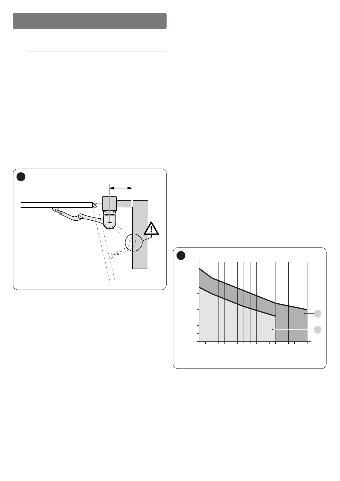
– make sure that there is enough space in the installation
location for the gearmotor’s arm to rotate fully (see “Figure 2“)
2
– keep the product away from heat sources and open ames and
acid, saline or potentially explosive atmospheres; these may
damage the product and cause malfunctions or dangerous
situations
– if there is an access door in the gate, or within its range of
movement, make sure that it does not obstruct the gate’s
normal path; install an appropriate interlock system if
necessary
– connect the control unit to an electricity supply line equipped
with a safety earthing system
– connect the gate to the earthing device in accordance with
the current legislation
– include a device on the electric power line ensuring
complete disconnection of the automation from the grid. The
disconnection device must have contacts with a sufcient
gap to ensure complete disconnection, under the Category
III overvoltage conditions, in accordance with the installation
instructions. Should it be necessary, this device guarantees
fast and safe disconnection from the power supply; it must
therefore be positioned in view of the automation. If placed in
a non-visible location, it must have a system that blocks any
accidental on unauthorised reconnection of the power supply,
in order to prevent dangerous situations. The disconnection
device is not supplied with the product.
3.2 PRODUCT USAGE LIMITS
Carry out the following checks before installing the gearmotor:
– check that the leaf to be automated falls within the specied
values (see “Figure 3“)
– maximumwidth of the leaf: 3,5 m (with weight up to 200 kg)
– maximumweight of the leaf: 330 kg (with width up to 1,8 m)
– verify the limits for the values shown in the “TECHNICAL
SPECIFICATIONS” chapter
– minimumwidthof the space reserved for the gearmotor’s
installation: 210 mm
– the arm’s xing bracket must be attached to a sturdy point of
the leaf (for example, the frame), to guarantee solid and safe
anchoring.
– verify that there are no points of greater friction during the
opening and closing movements along the entire gate path
– verify that the overrun mechanical stops are sturdy enough
and that they do not deform even if the leaf should strike them
forcefully
– verify that the gate leaf is well balanced: it must not move by
itself when left in any position
– make sure that the installation area is not subject to ooding; if
necessary, the product must be installed appropriately raised
above ground level
– verify that the area where the gearmotor is installed allows for
unlocking the latter and manoeuvring easily and safely
– verify that the mounting positions of the various devices are
protected against impacts and that the mounting surfaces are
sufciently sturdy
– prevent any parts of the automation from being immersed in
water or other liquids
3
300
250
200
150
100
1,8 2,0 2,2 2,4 2,6 2,8 3,0 3,2 3,4
A For arm with FULL length
B For arm with REDUCED length
A
B
4 – ENGLISH

3.2.1 Product durability
Durability in cycles (No.)
Severity index (%)
The product’s durability is its average economic life value and is
strongly inuenced by the degree of severity of the manoeuvres:
in other words, the sum of all factors that contribute to product
wear.
To estimate the durability of your automated device, proceed
as follows:
1. add the values of the items in “Table 1” relative to the
system’s conditions
2. in the graph shown in “Figure 4”, from the value obtained
above, trace a vertical line until it intersects the curve;
from this point trace a horizontal line until it intersects the
line of the “manoeuvre cycles”. The value obtained is the
estimated lifetime of your product.
The durability values shown in the graph can only be obtained
if the maintenance schedule is strictly observed – see the “
PRODUCT MAINTENANCE” chapter. The durability is estimated
on the basis of the design calculations and the results of tests
effected on prototypes. Being an estimate, therefore, it offers no
explicit guarantee of the product’s actual useful life.
Example of lifetime calculation: automation of a gate with
a 2,8 m-long leaf weighing 230 kg, for example with a solid
leaf.
“Table 1” shows the “severity indices” for this type of installation:
20% (“Door length”), 20% (“Door weight”) and 15% (“Solid leaf”).
These indicators must be added together to obtain the overall
severity index, which in this case is 55%. With the value
identied (55%), look at the horizontal axis of the graph (“severity
index”) and identify the value corresponding to the number of
“manoeuvre cycles” that the product can perform throughout its
lifetime – roughly 220.000 cycles.
Table 1
PRODUCT DURABILITY
Severity index
arm with
REDUCED
length
15%
20%
30%
30%
40%
-
< 1,8 m
Leaf length
Leaf weight
Ambient temperature greater
than 40°C or below 0°C, or
humidity greater than 80%
Solid leaf
Installation in windy areas
1,8 - 2,5 m
2,5 - 3,0 m
3,0 - 3,5 m
< 200 kg
200 - 250 kg
> 250 kg
arm with FULL
length
0%
15%
20%
30%
0%
20%
30%
20% 20%
15% 20%
15% 20%
4
500000
400000
300000
200000
10000
3.3 PRODUCT IDENTIFICATION AND OVERALL DIMENSIONS
The overall dimensions and the label (A), which allows for
identifying the product, are shown in “Figure 5”.
5
A
320 mm
210 mm 290 mm
Note The data refers to a properly balanced sectional door in
good working order.
ENGLISH – 5

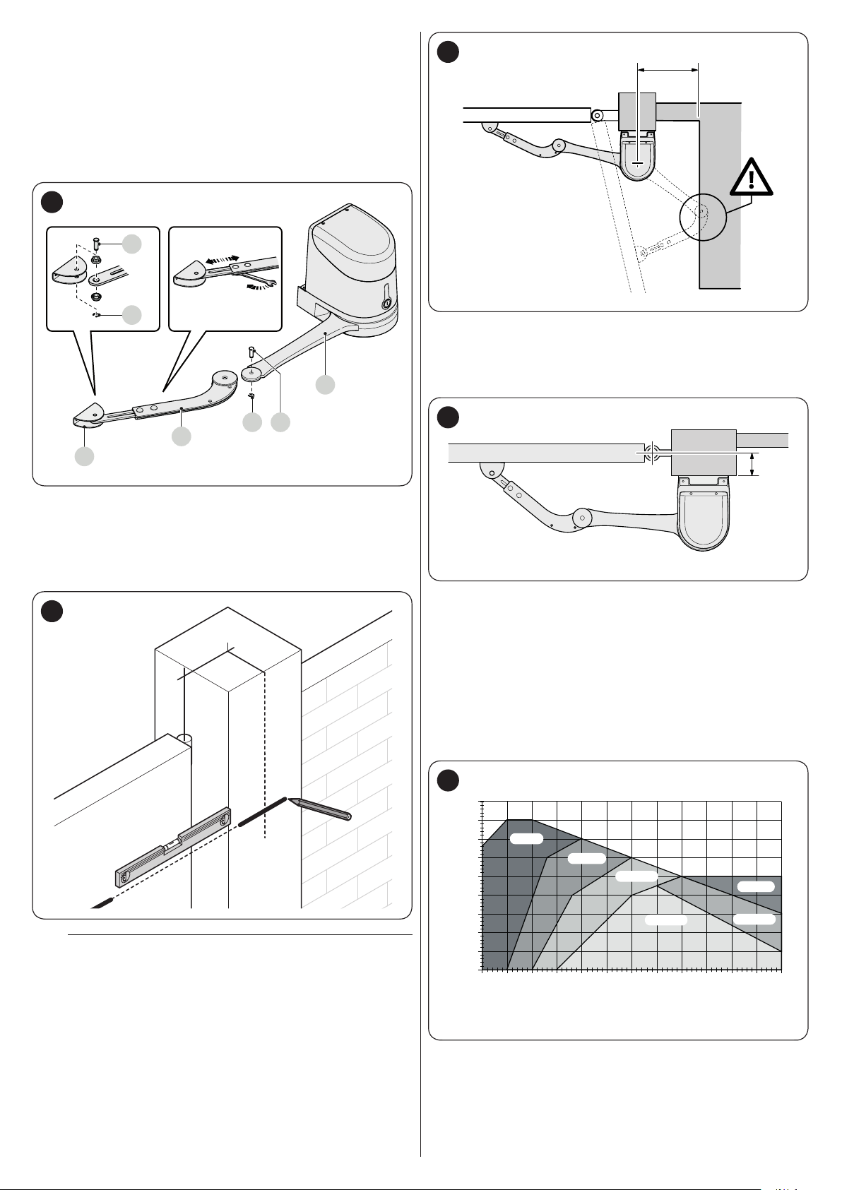
3.4 PRE-INSTALLATION WORKS
A B
4
ED G H AC C F
The gure shows an example of an automation system, constructed using Nice components.
6
2
3
4
A Photocells on column
B Gearmotor without control unit (models HK7224 and
HK7224HS)
C Photocells (model EPM)
D Mechanical stop at closed position
E Electric lock
F Warning light MLBT
G Gearmotor with control unit (models HK7024 and HK7024HS)
H Digital keypad (model EDSB) - Transponder reader (model
ETPB) - Key selector EKSU)
These above-mentioned components are positioned according
to a typical standard layout. Using the layout in “Figure 6” as
a reference, dene the approximate position in which each
component of the system will be installed.
Table 2
TECHNICAL SPECIFICATIONS OF ELECTRICAL CABLES
Identication no. Cable characteristics
1
2
3
4
5
6
7
CONTROL UNIT POWER SUPPLY cable
1 cable 3 x 1.5 mm
Maximum length 30 m [note 1]
WARNING LIGHT cable
1 cable 2 x 0.5 mm
Maximum length 20 m
ANTENNA cable
1 x RG58-type shielded cable
Maximum length 20 m; recommended < 5 m
BLUEBUS DEVICES cable
1 cable 2 x 0.5 mm
Maximum length 20 m [note 2]
KEY SELECTOR cable
2 cables 2 x 0.5 mm
Maximum length 50 m
ELECTRIC LOCK cable
1 cable 2 x 1 mm
Maximum length 6 m
GEARMOTOR POWER SUPPLY cable
1 cable 3 x 1.5 mm
Maximum length 10 m [note 4]
ENCODER CONNECTION cable
1 cable 2 x 1 mm
Maximum length 10 m [note 4]
2
2
2
2
2
2
2
[note 3]
67
Note 1 If the power supply cable is longer than 30 m, a cable
with larger cross-sectional area (3 x 2.5 mm
14 5
2
) must be
used and a safety earthing system must be installed
near the automation.
Note 2 If the BlueBus cable is longer then 20 m, up to maximum
40 m, it is necessary to use a cable with a greater crosssectional area (2 x 1 mm
Note 3 These two cables can be replaced by a single 4 x 0.5
mm
2
cable.
2
).
Note 4 This cable can be replaced by a single 5 x 1.5 mm
cable.
Before proceeding with the installation, prepare
a
the required electrical cables by referring to
“Figure 6” and to that stated in the “TECHNICAL
SPECIFICATIONS” chapter.
The cables used must be suited to the type of
a
environment of the installation site.
When laying the pipes for routing the electrical
a
cables, take into account that any water deposits in
the junction boxes may cause the connection pipes
to form condensate inside the control unit, thus
damaging the electronic circuits.
3.5 INSTALLING THE GEARMOTOR
Incorrect installation may cause serious physical
a
injury to the person working on the system or to its
future users.
Before starting to assemble the automation,
complete the preliminary checks described in the “
Pre-installation checks” and “Product usage limits”
paragraphs.
2
6 – ENGLISH
Before starting the installation, it is necessary to determine
E
E
450
B
A
450
the length of the gearmotor arm – refer to the paragraph “
Determining the length of the gearmotor arm”.
3.5.1 Determining the length of the gearmotor arm
Assemble the components making up the motor arm::
1. attach the curved arm (A) to the straight arm (B) using the
pin (C) and retaining ring (D). likewise, attach the xing
bracket for the gate leaf (E) to the curved arm (A)
7
C
D
B
9
3.5.2 Installing the gearmotor with FULL-LENGTH ARM
To install HYKE:
1. measure the distance (B)
D
C
A
2. to dene the position of the gearmotor VERTICALLY,
draw a horizontal line on the pillar at the same height at
which the arm’s xing bracket will be on the leaf, after the
installation
3. dene the position of the gearmotor HORIZONTALLY
[level A].
8
A
If there is a xed obstacle (wall, tree, etc.) near the
a
installation area, measure distance E then proceed
as follows:
– If distance (E) is equal to or above 650 mm, consult
the paragraph “Installing the gearmotor with FULL-
LENGTH ARM”
– If distance (E) is between 300 mm (minimum) and 650
mm (maximum), consult the paragraph “Installing the
gearmotor with REDUCED-LENGTH ARM”.
10
B
2. move the leaf to the desired maximum opening position
(maximum 110°) and check the resulting opening angle
3. mark the resulting distance (B) on the graph and, from
this point, draw a horizontal line intersecting the area that
includes the value of the measured opening angle
4. in the points of intersection between the horizontal line
and the area, draw a few vertical lines to determine the
values that can be used for level (A); choose in this range
a value for level (A). For example: if (B) is 200 mm and the
desired angle is 110°, level (A) will be between 300 mm
and 345 mm
11
400
350
300
250
200
150
100
50
90°-95°
95°-100°
100°-105°
105°-110°
0
150 175 200 225 250 275 300 325 350 400375 425
90°-95°
95°-105°
ENGLISH – 7

5. use the xing bracket (C), in the horizontal position, as a
template to determine the position of the four xing holes
8. attach the gearmotor to the bracket using the two screws
(D) provided
12
A
C
6. drill the bracket in the marked positions
13
15
D
9. unlock the gearmotor manually (see paragraph “Manually
unlocking and locking the gearmotor“)
10. decide where to attach the bracket to the gate leaf, by
extending the gearmotor arms as far as possible
7. attach the xing bracket (C) of the gearmotor to the wall
using adequate wall plugs, screws and washers (not
supplied)
14
It is important to position the bracket at the farthest
m
point with respect to the position of the gearmotor.
Make sure that the arm stops at its limit switch.
16
OK
OK
8 – ENGLISH
C
x 4

11. drill the leaf
450
B
A
450
12. separate the xing bracket from the curved arm by
removing the retaining ring and the relative pin
17
19
90°
2
90°
3
17. if the gate to be automated has two leaves, repeat all the
operations described above to install the other gearmotor.
13. fasten the bracket to the gate leaf in the horizontal position,
using adequate screws (not supplied)
18
14. fasten the arm to the bracket again using the pin and
retaining ring just removed
15. before locking the gearmotor, adjust the limit switches (see
paragraph “Adjusting the mechanical limit switches“)
16. manually bring the gate leaf to roughly midway along its
path and lock the gearmotor as explained in the paragraph
“Manually unlocking and locking the gearmotor”. Then
manually move the gate leaf by a few centimetres in the
opening direction
3.5.3 Installing the gearmotor with REDUCED-LENGTH ARM
With this conguration, the maximum allowed
m
opening angle for the leaf is 90°.
To install HYKE:
1. measure the distance (B)
20
B
2. mark the resulting distance (B) on the graph and, from this
point, draw a horizontal line intersecting the area between
90° and 95°
3. in the points of intersection between the horizontal line
and the area, draw a few vertical lines to determine the
values that can be used for level (A); choose in this range
a value for level (A). For example: if (B) is 200 mm and the
desired angle is 95°, level (A) will be between 400 mm
and 450 mm
21
400
350
300
250
200
150
100
50
90°-95°
95°-100°
100°-105°
105°-110°
0
150 175 200 225 250 275 300 325 350 400375 425
90°-95°
95°-105°
ENGLISH – 9

4. use the xing bracket (C), in the horizontal position, as a
template to determine the position of the four xing holes
7. attach the gearmotor to the bracket using the two screws
(D) provided
22
A
C
5. drill the bracket in the marked positions
23
25
D
8. unlock the gearmotor manually (see paragraph “Manually
unlocking and locking the gearmotor“)
9. draw the arm towards the leaf and place the xing bracket
on the latter
6. attach the xing bracket (C) of the gearmotor to the wall
using adequate wall plugs, screws and washers (not
supplied)
24
Push the curved arm against the leaf using your
m
hands, until the arm locks (maximum opening).
26
OK
OK
10 – ENGLISH
C
x 4

10. while keeping the bracket against the leaf with one hand,
move the leaf to the maximum opening position and check
that the arm does not collide with any obstacles
27
11. drill the leaf
12. separate the xing bracket from the curved arm by
removing the retaining ring and the relative pin
28
13. fasten the bracket to the gate leaf in the horizontal position,
using adequate screws (not supplied)
29
14. fasten the arm to the bracket again using the pin and
retaining ring just removed
15. before locking the gearmotor, adjust the limit switches (see
paragraph “Adjusting the mechanical limit switches“)
16. manually bring the gate leaf to roughly midway along its
path and lock the gearmotor as explained in the paragraph
“Manually unlocking and locking the gearmotor”. Then
manually move the gate leaf by a few centimetres in the
opening direction
30
90°
2
3
90°
3
~45°
17. if the gate to be automated has two leaves, repeat all the
operations described above to install the other gearmotor.
ENGLISH – 11
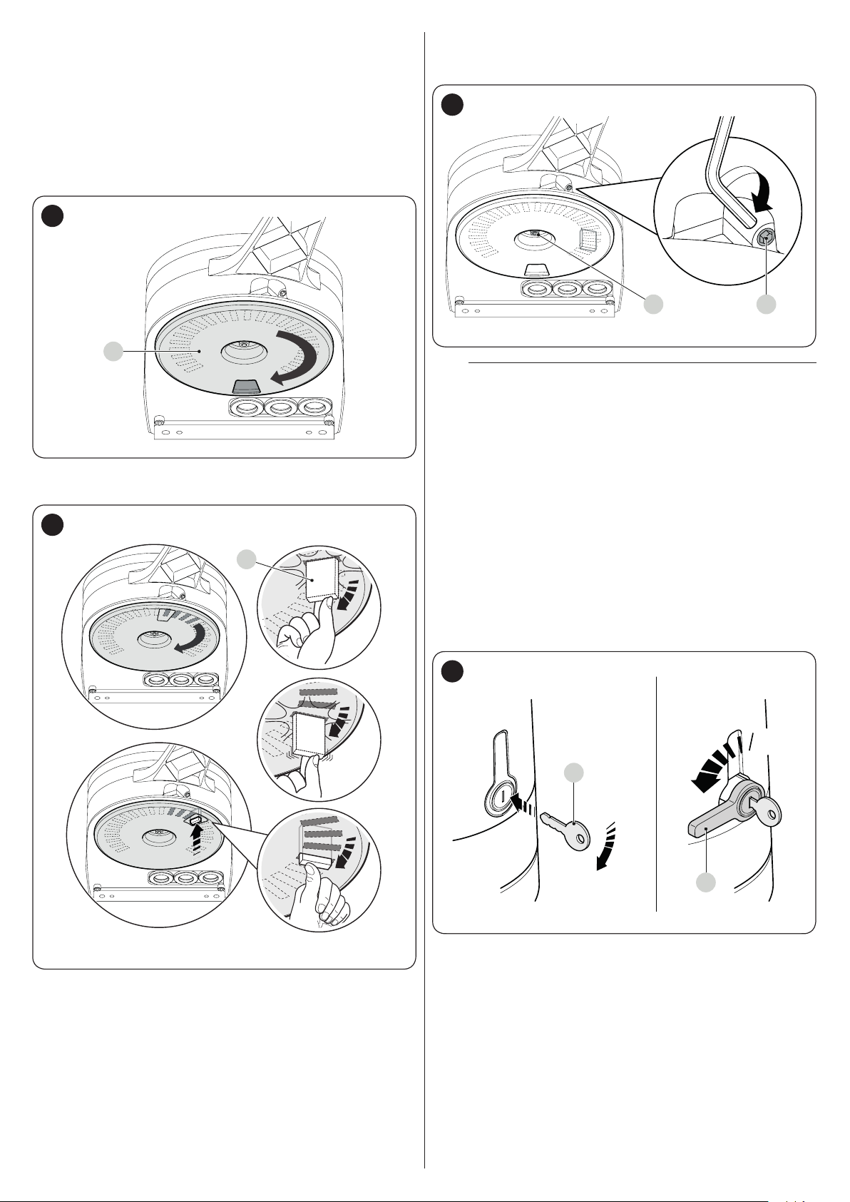
3.6 ADJUSTING THE MECHANICAL LIMIT
OK
NO
NO
SWITCHES
To adjust the limit switches, proceed as follows:
1. unlock the gearmotor with the relevant key provided (refer
to the “Manually unlocking and locking the gearmotor”
paragraph)
2. manually move the gate leaves to the fully open position
3. turn the plastic disc (A), located on the lower part of the
gearmotor, moving the slot under the arm to the position
shown
31
A
5. turn the disc (A) so that the limit switch does not fall and
move the slot towards the position shown in “Figure 31”.
For a ner adjustment, turn the adjustment screw (C)
33
CD
If the system has no closing stop on the ground,
m
the entire procedure must be repeated to adjust the
closing limit switch as well
6. fully tighten the nut fastening the disc (D) to prevent the
latter from turning accidentally.
4. insert the limit switch (B) in the rst available position: try
inserting it as indicated
32
B
3.7 MANUALLY UNLOCKING AND LOCKING THE GEARMOTOR
The gearmotor is equipped with a mechanical unlocking device
that can be used to open and close the gate manually.
These manual operations should only be performed in case of
a power outage, malfunctions or during the installation phases.
To unlock the device:
1. insert the key (A) and turn it clockwise by 90°
2. turn the lever (B) by 90° anti-clockwise which, by effect of
a spring, has come out of its housing
34
90°
A
90°
B
12 – ENGLISH
3. the gate leaf can now be moved manually to the desired
position.
To lock the device:
1. turn the lever (B) by 90° until it lies in the vertical position
2. push the lever until it slots into its housing
3. turn the key (A) by 90° anti-clockwise
4. remove the key.
4
4 ELECTRICAL CONNECTIONS
ELECTRICAL CONNECTIONS
4.1 PRELIMINARY CHECKS
All electrical connections must be made with the
f
system disconnected from the mains electricity and
with the back-up battery (if present) disconnected.
The connection operations must only be carried out
a
by qualied personnel.
Mount a device on the electric power line that
f
completely disconnects the automation from the
grid.
– The disconnection device must have contacts with a
sufcient gap to ensure complete disconnection, under
the Category III overvoltage conditions, in accordance
with the installation instructions.
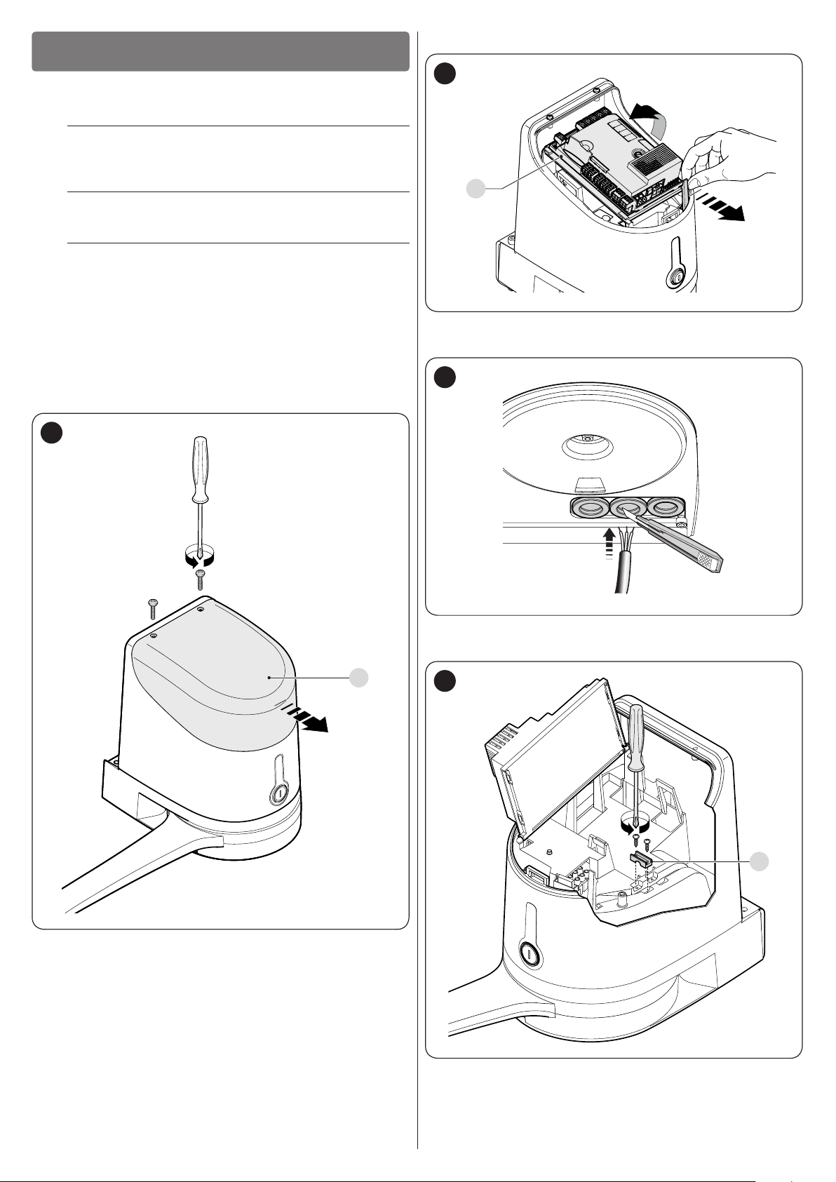
2. lift the control unit (B) of the gearmotor
36
B
3. pass the power cable and the other electrical cables
through the hole on the lower part of the gearmotor
To make the electrical connections:
1. open the gearmotor’s cover (A)
35
37
4. rst connect the motor’s power cable with control units
HK7024 and HK7024HS: loosen the cable clamp (C)
A
38
C
ENGLISH – 13

5. connect the power cable (D) and lock it in place with the
D
cable clamp (C)
39
C
6. use the same procedure to connect the power cable to the
motor without the control units HK7224 and HK7224HS
7. connect the cables of any supplementary devices, by
referring to “Figure 41” and to the “Photocells” paragraph
8. close the covers of the gearmotor.
40
A
14 – ENGLISH

4.2 WIRING DIAGRAM AND DESCRIPTION OF CONNECTIONS
4.2.1 Wiring diagram
41
FLASH
EL
ENC ENC
OGI
ELS
Flash
OGI
24V 4W
1 2 3 4 5 6 7 8 9
1011 12
TX
Bluebus Bluebus
Bluebus
Nice S.p.A.
Via Callalta, 1
31046 Oderzo
TV Italy
RX
NO
NC
8K2
CloseOpenSbSStop
NO
NONO NO
M M
M1
M M
M2
4.2.2 Description of connections
ELECTRICAL CONNECTIONS
Terminals Description
Connection of motor M1 [note 1]
Connection of motor M2
Flash
ELS
OGI
ENC
ENC
Bluebus
Output for warning light mounting a 12 V (maximum 21 W) lamp. The output can be programmed (refer to the “
Level 1 programming (ON-OFF)” paragraph).
Output for 12 Va (maximum 15 VA) electric lock. The output can be programmed (refer to the “Level 1
programming (ON-OFF)” paragraph).
“Open Gate Indicator” output for 24 V maximum 4 W signalling lamp. The output can be programmed (refer to the
“Level 1 programming (ON-OFF)” paragraph).
Motor 1 encoder input. No pole markings to observed
Motor 2 encoder input. No pole markings to observed
Radio receiver antenna connection
Input for compatible devices (for example: EPLB, EPLOB, EPLIOB, ETPB, EDSB). The devices must be connected
in parallel through two conductors carrying both the power supply and the communication signals. It is not
necessary to observe the pole markings. During the learning function, each device connected to the control unit
will be individually recognised thanks to a univocal code. Whenever a device is added or eliminated, the control
unit must run the learning procedure (see “Device learning” paragraph).
Table 3
Note 1 Not used for single-leaf gates (the control unit automatically recognises whether there is only one motor installed).
ENGLISH – 15

ELECTRICAL CONNECTIONS
Terminals Description
Input for devices that through their intervention trigger the immediate stoppage of the current manoeuvre followed
by a brief reversal. NO (normally open) contacts, NC (normally closed) contacts or devices with 8.2 kΩ xed
resistor output, such as sensitive edges, can be connected to this input. Each device connected to this input
will be individually recognised by the control unit during the learning phase (see “Device learning” paragraph).
Stop
SbS
Open
Close
5
5 FINAL CHECKS AND START-UP
It is advisable to position the leaf approximately halfway along its
path before starting the automation check and start-up phases,
so that the leaf is free to open and close.
FINAL CHECKS AND START-UP
During this phase, if the control unit detects any variation with respect to the learned status, it triggers a STOP.
One or more devices, even different from one another, can be connected to this input: any number of NO inputs in
parallel; any number of NC inputs in series; 2 devices with 8.2 kΩ xed resistor output in parallel. If there are more
than 2 devices, they must all be connected in cascade mode with a single 8.2 kΩ terminating resistor; 2 NO and
NC devices in parallel, putting an 8.2 kΩ resistor in series with the NC contact (this also allows for combining 3
devices: NO, NC and 8.2 kΩ).
Input for a NO (normally open) button, for sending commands in step-by-step mode.
Input for command devices that trigger the opening manoeuvre only, when they intervene. NO (normally open)
contacts can be connected to this input.
Input for command devices that trigger the closing manoeuvre only, when they intervene. NO (normally open)
contacts can be connected to this input.
5.1 POWER SUPPLY CONNECTION
For this to occur, the device learning procedure must be carried
out whenever a device is added or removed.
42
CloseOpenSbSStop
1 2 3 4 5 6 7 8 9
Bluebus
10 11 12
The power supply connections must only be made
a
by qualied and experienced personnel possessing
the necessary requirements and in full conformity
to the laws, regulations and standards in force.
As soon as the product is powered, a few simple checks should
be carried out:
1. check that the “BlueBUS” LED ashes regularly with one
ash per second
2. check that the LEDs on the photocells (both the TX and
RX) also ash; the type of ashing is irrelevant, since it
depends on other factors
3. check that the warning light connected to the FLASH
output is off.
If the above conditions are not satised, immediately switch
off the power supply to the control unit and carefully check the
electrical connections.
Further useful information on searching and diagnosing faults is
included in the “TROUBLESHOOTING GUIDE” chapter.
5.2 DEVICE LEARNING
After the initial start-up, the control unit must recognise the
devices connected to the “Bluebus” and “Stop” inputs.
The learning phase must be carried out even if no
l
device is connected to the control unit.
The control unit can individually recognise the various devices
connected, thanks to the learning procedure, and detect
possible anomalies.
S
L1
L2
LEDs “L1” and “L2” on the control unit (“Figure 42”) emit
some slow ashes to signal that the learning procedure must
be carried out.
To do this:
1. simultaneously press and hold the
g
2. release the buttons when LEDs “L1” and “L2” start
ashing quickly (after roughly 3 seconds)
3. wait a few seconds until the control unit has completed the
device learning phase
4. once this phase terminates, the “Stop” (S) LED must be lit
and LEDs “L1” and “L2” must switch off (LEDs “L3” and
“L4” could start ashing).
buttons
f
and
16 – ENGLISH

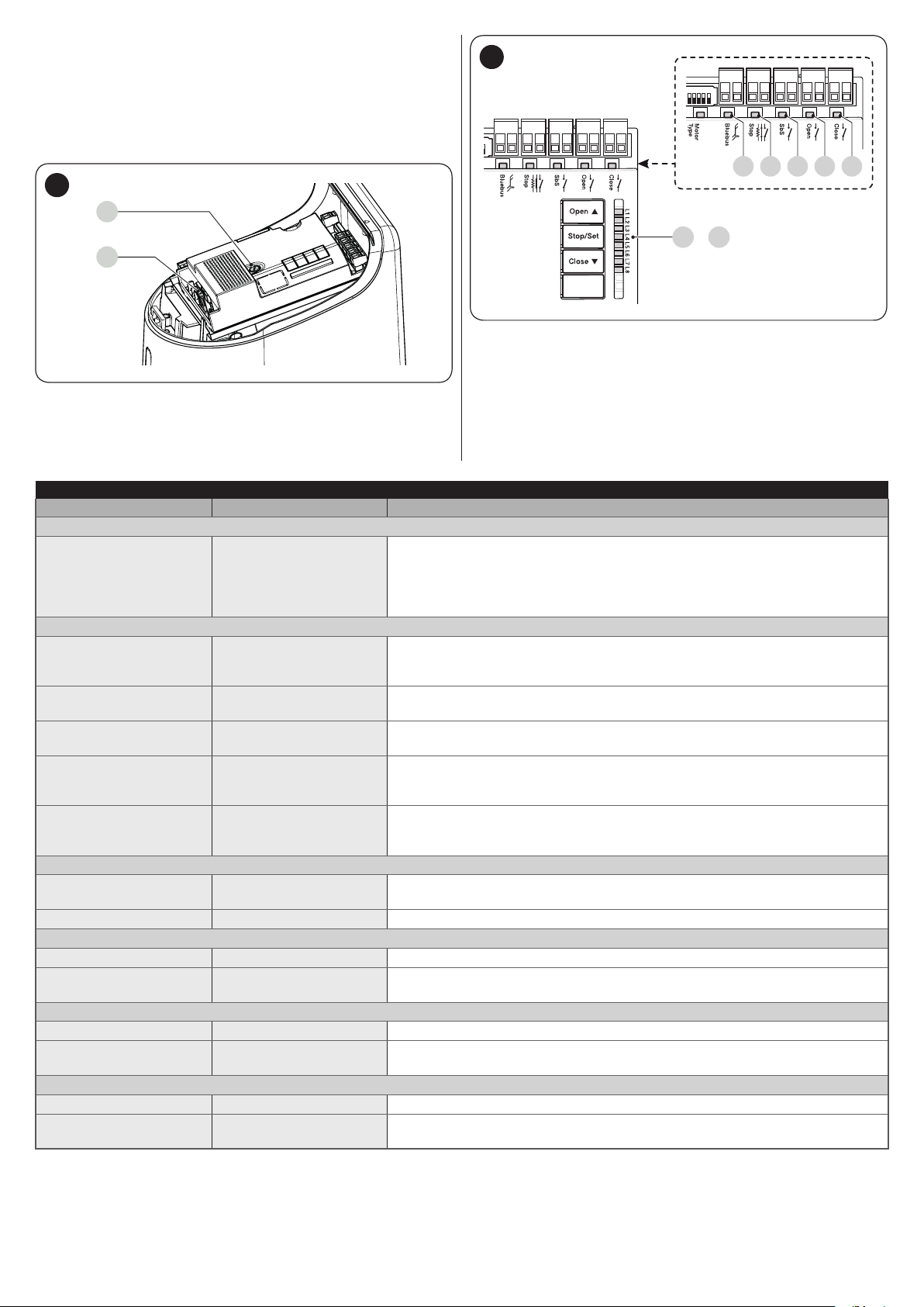
5.3 MOTOR SELECTOR
1
2 3 4 5 6 7 8 9 10 11 12
1
2 3 4 5 6 7 8 9 10 11 12
The control unit is equipped with a selector (A - “Figure 43”) that
allows for specifying which type of motor to use (see “Table 4”).
In the mixed mode, it is possible to perform the automatic
procedure and then, with the manual procedure, modify one or
more positions with the exception of the “0” and “1” positions,
which correspond to the mechanical stop positions.
43
A
Bluebus
1 2 3 4 5 6 7 8 9
The motor selector must be set before activating
m
10 11 12
CloseOpenSbSStop
the mechanical stop learning function.
Any conguration not appearing in “Table 4” is not
m
allowed.
Table 4
SELECTING THE MOTOR TYPE
Motor type Motor selector
O
HK7024
HK7024HS
N
O
N
Visualisation on
Oview
HYKE
HYKEHS
5.4 LEARNING OF THE MECHANICAL STOP POSITIONS
Once the connected devices have been learned, the mechanical
stop positions must be learned (maximum opening and
maximum closing). This procedure can be carried out in three
different ways: automatic, manual and mixed.
In automatic mode, the control unit learns the mechanical stops,
calculates the most appropriate gate leaf offsets and calculates
the slowdown points “SA” and “SC” (“Figure 44“).
Before starting the self-learning procedure in
a
automatic mode, verify that the motor force is suited
to the type of motor being used (see paragraph “
Level 2 programming (adjustable parameters) -
Function L5“).
In the manual mode, the positions (“Figure 44”) are programmed
one by one, by shifting the leaves to the desired points. The
position to be programmed can be identied when one of the
eight LEDs “L1...L8” ashes (see “Table 5“).
44
1 1
A
SC
SA
0 0
M1 M2
PROGRAMMING POSITIONS
Position LED Description
Position 0
(motor 1)
Position 0
(motor 2)
Position SA
(motor 2)
Position A
(motor 1)
Position A
(motor 2)
Position SC
(motor 1)
Position 1
(motor 1)
Position 1
(motor 2)
maximum closing position: when the
leaf relative to motor 1 strikes the
L1
closing mechanical stop
maximum closing position: when the
leaf relative to motor 2 strikes the
L2
closing mechanical stop
Offset on opening: when the leaf
associated with motor 2 moves
L3
beyond this position, leaf 1 will start
to open
Desired opening position: position in
which the leaf associated with motor
1 must stop at the end of an opening
manoeuvre. This position must
L4
not necessarily correspond to the
opening mechanical stop; it can be
chosen as desired between positions
“0” and “1”
Desired opening position: position in
which the leaf associated with motor
2 must stop at the end of an opening
manoeuvre. This position must
L5
not necessarily correspond to the
opening mechanical stop; it can be
chosen as desired between positions
“0” and “1”
Offset on closing: when leaf 1 is
below this position, leaf 2 will start to
L6
close
Maximum opening position: when
the leaf relative to motor 1 strikes the
L7
opening mechanical stop
Maximum opening position: when
the leaf relative to motor 2 strikes the
L8
opening mechanical stop
A
Table 5
ENGLISH – 17

5.4.1 Learning in automatic mode
45
L3
L4
To effect the automatic learning procedure:
1. simultaneously press and hold the and
g
buttons
h
2. release the buttons when LEDs “L3” and “L4” start
ashing quickly (after roughly 5 seconds)
3. check that the automation carries out the following
manoeuvre sequences:
a. slow closing of motor M1 up to the mechanical stop
b. slow closing of motor M2 up to the mechanical stop
c. slow opening of motor M2 and of motor M1 up to the
stop
d. fast closing of motors M1 and M2.
If the rst manoeuvre (a) fails to close the leaf
m
controlled by motor M1 but closes the one
controlled by M2, press
stop the learning phase. At this point, reverse the
connections of motors M1 and M2 on the terminals
on the control unit and those of the respective
encoders. Then repeat the self-learning procedure.
If the rst two manoeuvres (a and b) are not “closing”
m
but “opening” manoeuvres, press the
h
point, invert the control wires (external positions
with respect to the terminal) on the motor that
executed the opening manoeuvre and repeat the
self-learning procedure.
4. at the end of the closing manoeuvre (d) of the two motors,
LEDs “L3” and “L4” switch off to signal that the procedure
was performed correctly.
If, during the automatic learning procedure, the
m
photocells or one of the devices connected to the
“stop” input intervene, the procedure interrupts and
LED L1 starts ashing. In this case, the self-learning
procedure must be repeated from the beginning.
The automatic learning procedure can be run
l
again at any time, even after the installation phase;
for example, after modifying the position of the
mechanical stops.
button to stop the learning phase. At this
f
or
h
f
to
or
5.4.2 Learning in manual mode
The user has maximum 10 seconds to press
m
the buttons consecutively during the learning
procedure. After this time, the procedure terminates
automatically and memorises the changes made up
to that time.
46
L3
L4
When LEDs "L1..L8" ash, to shift between LEDs
l
simply press the
(the LED will ash to signal the current position).
While LEDs "L1..L8" ash, to move the motor in any
l
one direction, it is necessary to press and hold the
f
To effect the manual learning procedure:
1. simultaneously press and hold the and
or
f
h
or
button.
h
g
button briey
buttons
h
2. release the buttons when LED “L1” starts ashing (after
roughly 3 sec)
3. LED “L1” ashes: position 0 of M1
– to command and move motor 1 to position “0” (“Figure
44”): press and hold the
Once the position is reached, release the button to stop
the manoeuvre
– to memorise the position, press and hold the
button for at least 3 seconds then release it (after 2
seconds LED “L1” will remain lit and after the
button is released, LED “L2” will start ashing)
4. LED “L2” ashes: position 0 of M2
– to command and move motor 2 to position “0” (“Figure
44”): press and hold the
Once the position is reached, release the button to stop
the manoeuvre
– to memorise the position, press and hold the
button for at least 3 seconds then release it (after 2
seconds LED “L2” will remain lit and after the
button is released, LED “L3” will start ashing)
5. LED “L3” ashes: position SA of M2
– to command and move motor 2 to position “SA”
(“Figure 44”): press and hold the
h
release the button to stop the manoeuvre
– to memorise the position, press and hold the
button for at least 3 seconds then release it (after 2
seconds LED “L3” will remain lit and after the
button is released, LED “L4” will start ashing)
button. Once the position is reached,
f
f
or
h
or
h
button.
g
g
button.
g
g
f
g
g
or
18 – ENGLISH

6. LED “L4” ashes: position A of M1
– to command and move motor 1 to position “A” (“Figure
44”): press and hold the
Once the position is reached, release the button to stop
the manoeuvre
– to memorise the position, press and hold the
button for at least 3 seconds then release it (after 2
seconds LED “L4” will remain lit and after the
button is released, LED “L5” will start ashing)
7. LED “L5” ashes: position A of M2
– to command and move motor 2 to position “A” (“Figure
44”): press and hold the
Once the position is reached, release the button to stop
the manoeuvre
– to memorise the position, press and hold the
button for at least 3 seconds then release it (after 2
seconds LED “L5” will remain lit and after the
button is released, LED “L6” will start ashing)
8. LED “L6” ashes: position SC of M1
– to command and move motor 1 to position “SC”
(“Figure 44”): press and hold the
h
release the button to stop the manoeuvre
– to memorise the position, press and hold the
button for at least 3 seconds then release it (after 2
seconds LED “L6” will remain lit and after the
button is released, LED “L7” will start ashing)
9. LED “L7” ashes: position 1 of M1
– to command and move motor 1 to position “1” (“Figure
44”): press and hold the
Once the position is reached, release the button to stop
the manoeuvre
– to memorise the position, press and hold the
button for at least 3 seconds then release it (after 2
seconds LED “L7” will remain lit and after the
button is released, LED “L8” will start ashing)
10. LED “L8” ashes: position 1 of M2
– to command and move motor 2 to position “1” (“Figure
44”): press and hold the
Once the position is reached, release the button to stop
the manoeuvre
– to memorise the position, press and hold the
button for at least 3 seconds then release it (after 2
seconds, LED “L8” will remain lit and after the
button is released).
button. Once the position is reached,
f
f
f
f
or
h
or
h
or
h
or
h
button.
g
g
button.
g
g
f
g
g
button.
g
g
button.
g
g
5.4.3 Learning in mixed mode
The user has maximum 10 seconds to press
m
the buttons consecutively during the learning
procedure. After this time, the procedure terminates
automatically and memorises the changes made up
to that time.
47
or
To effect the learning procedure in mixed mode:
1. run the self-learning procedure in automatic mode as
described under the “Learning in automatic mode”
paragraph
2. simultaneously press and hold the and
L3
L4
g
h
3. release the buttons when LED “L1” starts ashing
4. briey press the
ashing LED (L1…L8) to the position to be programmed
5. repeat this last operation for all the other positions to be
modied
6. to terminate the manual learning procedure, press the
h
to beyond position “L8”.
f
button repeatedly to shift the LED that ashes
o
h
button to shift the
5.5 CHECKING THE GATE MOVEMENT
At the end of the learning phase, we recommend letting the
control unit run a few opening and closing manoeuvres to verify
whether the gate moves correctly and if there are any assembly
and adjustment defects.
48
buttons
If the system has a single motor only:
a
– proceed as described at points 1 and 2
– at points 3 and 9, press and hold the
for at least 3 seconds then release it
– after 2 seconds, the relative LED will remain lit until the
g
start ashing.
button is released. The next LED will then
g
Do not programme the positions relative to LEDs
L3 (SA of M2), L4 (A of M1) and L6 (SC of M1). To
shift between LEDs, simply press the
h
button briey (the LED will ash to signal
f
the current position).
button
or
1. To do this:
2. press the
the acceleration, constant-speed and slowdown phases
are present during the opening manoeuvre. Once the
manoeuvre terminates, the gate leaves must stop a few
centimetres from the opening mechanical stop
3. press the
the acceleration, constant-speed and slowdown phases
are present during the closing manoeuvre. Once the
manoeuvre terminates, the gate leaves must be perfectly
closed on the closing mechanical stop
4. check that all the previously adjusted functions have been
learned by the control unit.
f
h
button (“Figure 48”). Check that
button (“Figure 48”) and verify that
ENGLISH – 19

5.6 CONNECTING OTHER DEVICES TO THE CONTROL UNIT
In any additional devices belonging to the system (e.g.
transponder card reader, light for the key selector, etc.) must
be powered, they can be connected to the control unit using
terminals “SbS (positive)” and “Stop (negative)” (“Figure 41”).
The power supply voltage is 24 Vc with a maximum available
current of 200 mA.
The voltage available at the “SbS” and “STOP”
l
terminals remains even when the “Stand-by”
function is enabled on the board.
6
6 TESTING AND COMMISSIONING
These are the most important phases of the automation’s
construction, as they ensure maximum safety of the system. The
test can also be used to periodically verify the devices making
up the automation.
m
The additional devices must undergo specic testing, both in
terms of their functions and their proper interaction with the
control unit. Refer to the instruction manuals of the individual
devices.
TESTING AND COMMISSIONING
Testing and commissioning of the automation must
be performed by skilled and qualied personnel,
who are responsible for the tests required to
verify the solutions adopted according to the risks
present, and for ensuring that all legal provisions,
standards and regulations are met, in particular
all the requirements of the EN 12445 standard,
which denes the test methods for checking gate
automations.
6.2 COMMISSIONING
Commissioning can only be performed after all
a
testing phases have been successfully completed.
Before commissioning the automation, ensure that
a
the owner is properly informed of all residual risks
and hazards.
The gate cannot be commissioned partially or under
a
“temporary” conditions.
To commission the automation:
1. compile the automation’s technical le, which must
include the following documents: overall drawing of the
automation, wiring diagram, risk assessment and relative
solutions adopted, the manufacturer’s declaration of
conformity for all devices used and the declaration of
conformity compiled by the installer
2. afx a permanent label or sign near the gate specifying
the operations for unlocking the gate and manoeuvring it
manually “Figure 49“
49
90°
6.1 TESTING
To run the test:
1. verify that all the instructions stated in the “GENERAL
SAFETY WARNINGS AND PRECAUTIONS” chapter
have been strictly observed
2. unlock the gearmotor as indicated in the “Manually
unlocking and locking the gearmotor” paragraph
3. make sure that the leaf can be moved manually during
both the opening and closing phases with a force not
exceeding 390N (roughly 40 kg)
4. lock the gearmotor
5. using the control devices (transmitter, control button,
key selector, etc.), test the gate’s opening, closing and
stoppage movements to make sure that the leaves move
as intended. Several tests should be carried out to assess
the movement of the leaves and detect any defects in
the installation and adjustment, besides any points of
excessive friction
6. check, one-by-one, that all safety devices mounted on the
system (photocells, sensitive edges, etc.) work properly.
Each time a device intervenes, the “Bluebus” LED on
the control unit will emit two faster ashes to conrm the
recognition
7. if potentially dangerous situations due to the movement
of the leaves have been prevented by limiting the impact
force, the latter must be measured according to the EN
12445 standard and, if the “motor force” control is used to
aid the system in reducing the impact force, it is necessary
to test various adjustments to nd the one that gives the
best results.
3. afx a data plate on the gate specifying at least the
following data: type of automation, name and address of
the manufacturer (responsible for commissioning), serial
number, year of manufacture and CE mark
4. compile the declaration of conformity of the automation
and hand it to the owner of the automation
5. compile the User Manual of the automation and hand it to
the owner of the automation
6. compile and provide the owner with the automation’s
“Maintenance schedule”, containing the maintenance
instructions for all the automation’s devices.
For all the above-mentioned documentation, Nice –
l
through its technical assistance service – provides
the following: pre-completed forms.
20 – ENGLISH

7
7 PROGRAMMING
There are 3 buttons on the control unit:
h
the control unit during the testing phase and to programme the
available functions.
The
PROGRAMMING
(“Figure 50”) which can be used both to command
i
button is not used.
f, g
and
50
The available programmable functions are grouped into two
levels and their operating status is signalled by eight LEDs “L1
... L8” located on the control unit (LED lit = function enabled;
LED off = function disabled).
7.1 USING THE PROGRAMMING BUTTONS
f
Selection button during the programming phase.
g
If pressed for more than 5 seconds, it allows for entering
h
Selection button during the programming phase.
Button for commanding the gate opening
Button used to stop a manoeuvre
the programming mode.
Button for commanding the gate’s closure
i
– Button not used.
7.2 LEVEL 1 PROGRAMMING (ON-OFF)
All the Level 1 functions are factory-set to “OFF” and can be modied at any time. To check the various functions, refer to “Table 6”.
7.2.1 Level 1 programming procedure
The user has maximum 10 seconds to press the buttons consecutively during the programming procedure,
m
after which time the procedure terminates automatically and memorises the changes made up to then.
To perform Level 1 programming:
1. press and hold the
2. release the
3. press the
4. press the
– short ash = OFF
– long ash = ON
5. wait 10 seconds (maximum time) to exit the programming mode.
To set other functions to “ON” or “OFF”, while the procedure is running, repeat points 2 and 3 during the phase
l
g
f
g
g
button when LED “L1” starts ashing
or
button to change the status of the function:
itself.
LEVEL 1 FUNCTIONS (ON-OFF)
LED
Function Description
L1 Automatic closing
L2 Close after photo
L3 Always Close
L4 Stand-by all
Function ENABLED: after an opening manoeuvre there is a pause (equal to the set pause time), after which
the control unit automatically starts a closing manoeuvre. The pause time is set by default to 30 seconds.
Function NOT ENABLED: the system works in “semi-automatic” mode.
Function ENABLED: if the photocells intervene during the opening or closing manoeuvre, the pause time
drops to 5 seconds regardless of the set “pause time”. With “automatic closing” disabled, if the photocells
intervene during the opening or closing manoeuvre, the “automatic closing” activates with the set “pause
time”.
Function ENABLED: in the event of a blackout, even of short duration, 10 seconds after the electricity
is restored the control unit detects that the gate is open and automatically starts a closing manoeuvre,
preceded by 5 seconds of pre-ashing.
Function DISABLED: when the electricity is restored, the gate remains in the same position.
Function ENABLED: 1 minute after the manoeuvre is completed, the control unit will turn off the “Bluebus”
output (connected devices) and all the LEDs, with the exception of the Bluebus LED, which will ash at a
slower speed. When the control unit receives a command, it restores normal operation (with a short delay).
This function is used to reduce consumption – an important aspect when the unit is powered by batteries or
photovoltaic panels.
button until LED “L1” starts ashing
h
button to move the ashing LED to the LED associated with the function to be modied
Table 6
ENGLISH – 21

LEVEL 1 FUNCTIONS (ON-OFF)
LED
Function Description
Warning /
L5
Courtesy light
L6 Pre-ashing
“Close” becomes
L7
“Partial Open 1”
“Gate open
indicator” or
L8
“Maintenance
indicator”
Function ENABLED: the “electric lock” output switches its operation to “courtesy light”.
Function NOT ENABLED: the output functions as an electric lock.
Function ENABLED: the warning light starts ashing 3 seconds before the start of the manoeuvre to signal
in advance a dangerous situation.
Function NOT ENABLED: the warning light starts ashing when the manoeuvre starts.
Function ENABLED: the “Close” input of the control unit switches its operation to “Partial Open 1”.
Function ENABLED: the “gate open indicator” output of the control unit switches its operation to
“maintenance indicator”.
Function NOT ENABLED: the output functions as a “gate open indicator”.
7.3 LEVEL 2 PROGRAMMING (ADJUSTABLE PARAMETERS)
All the Level 2 parameters are factory-set as highlighted in “GREY” in “Table 7” and can be modied at any time. The parameters
can be set to a scale of 1 to 8. The check the value corresponding to each LED, refer to “Table 7”.
7.3.1 Level 2 programming procedure
The user has maximum 10 seconds to press the buttons consecutively during the programming procedure,
m
after which time the procedure terminates automatically and memorises the changes made up to then.
To perform Level 2 programming:
1. press and hold the
2. release the
3. press the
modied
4. press and hold the
– wait roughly 3 seconds, until the LED representing the current level of the parameter to be modied lights up
– press the
5. release the
6. wait 10 seconds (maximum time) to exit the programming mode.
g
f
g
g
or
g
f
button when LED “L1” starts ashing
or
button
button until LED “L1” starts ashing
h
h
button to move the ashing LED to the “entry LED” associated with the parameter to be
button. With the
button to shift the LED associated with the parameter’s value
g
button pressed:
To set multiple parameters during the procedure's execution, repeat the operations from point 2 to point 4
l
during the phase itself.
The set value highlighted in grey (“Table 7”) indicates that this value is the factory setting.
l
LEVEL 2 FUNCTIONS (ADJUSTABLE PARAMETERS)
Entry
LED
L1 Pause Time
Parameter
LED
(level)
L1 5 seconds
L2 15 seconds
L3 30 seconds
L4 45 seconds
L5 60 seconds
L6 80 seconds
L7 120 seconds
L8 180 seconds
Set value Description
Adjusts the pause time, in other
words, the time that elapses
before automatic re-closure.
It is only effective if the Close
function is enabled.
Table 7
22 – ENGLISH

LEVEL 2 FUNCTIONS (ADJUSTABLE PARAMETERS)
Entry
LED
Parameter
LED
(level)
Set value Description
L1 Open - Stop - Close - Stop
L2 Open - Stop - Close - Open
L3 Open - Close - Open - Close
CONDOMINIUM
During the opening manoeuvre, the “Step-by-Step” and
“Open” commands do not cause any effect; instead the
“Close” command causes the movement to reverse, namely
L4
the closing of the gate leaves.
During the closing manoeuvre, the “Step-by-Step” and
“Open” commands cause a reversal of the movement, namely
the opening of the gate leaves; instead the “Close” command
does not cause any effect.
CONDOMINIUM 2
L2
Step-by-Step
function
During the opening manoeuvre, the “Step-by-Step” and
“Open” commands do not cause any effect; instead the
“Close” command causes the movement to reverse, namely
the closing of the gate leaves. If the sent command remains
L5
for more than 2 seconds, a “Stop” command is executed.
During the closing manoeuvre, the “Step-by-Step” and
“Open” commands cause a reversal of the movement, namely
the opening of the gate leaves; instead the “Close” command
does not cause any effect. If the sent command remains for
more than 2 seconds, a “Stop” command is executed.
L6
STEP-BY-STEP 2 (less than 2 seconds causes partial
opening)
HOLD-TO-RUN
L7
The manoeuvre is only executed if the sent command
remains; if the command is interrupted, the manoeuvre stops.
L8 “Semi-automatic” opening, “hold-to-run” closing.
L1 Very slow
L2 Slow
L3 Medium
L3 Motor speed
L4 Fast
L5 Very fast
L6 Extremely fast
L7 Opens “Fast”; closes “Slow”
L8 Opens “Extremely fast”; closes “Medium”
L1 No discharge
L2 Level 1 - Minimum discharge (roughly 100 ms)
L3 Level 2 - ...
L4
Motor
discharge after
closing
L4 Level 3 - ...
L5 Level 4 - ...
L6 Level 5 - ...
L7 Level 6 - ...
L8 Level 7 - Maximum discharge (roughly 800 ms)
L1 Level 1 - Minimum force
L2 Level 2 - ...
L3 Level 3 - ...
L5 Motor force
L4 Level 4 - ...
L5 Level 5 - ...
L6 Level 6 - ...
L7 Level 7 - ...
L8 Level 8 - Maximum force
L1 Pedestrian 1 (the M2 gate leaf opens to 1/4 of the full length)
L2 Pedestrian 2 (the M2 gate leaf opens to 1/2 of the full length)
L3 Pedestrian 3 (the M2 gate leaf opens to 3/4 of the full length)
L4 Pedestrian 4 (full opening of gate leaf 2)
Partial 1 (the two gate leaves open to 1/4 of the “minimum”
opening level)
Partial 2 (the two gate leaves open to 1/2 of the “minimum”
opening level)
Partial 3 (the two gate leaves open to 3/4 of the “minimum”
opening level)
Partial 4 (the two gate leaves open to the “minimum” opening
level)
L6
Pedestrian or
partial opening
L5
L6
L7
L8
Controls the sequence of
commands associated with
the “SbS”, “Open” and “Close”
inputs or the radio control.
Note:
setting L4, L5, L7 and L8,
the behaviour of the “Open”
and “Close” commands also
changes.
Adjusts the motor speed during
normal travel.
Adjusts the duration of the
“brief reversal” of both motors,
after completing the closing
manoeuvre, to reduce the
residual nal thrust.
Adjusts the force of both motors.
Adjusts the type of opening
associated with the “partial
opening 1” command.
In levels L5, L6, L7 and L8,
“minimum” opening refers to
the smallest opening between
M1 and M2; for example, if M1
opens to 90° and M2 opens to
110°, the minimum opening is
90°.
ENGLISH – 23

LEVEL 2 FUNCTIONS (ADJUSTABLE PARAMETERS)
Entry
LED
L7
L8
Parameter
Maintenance
notication
List of
malfunctions
LED
(level)
L1 500
L2 1000
L3 1500
L4 2500
L5 5000
L6 10000
L7 15000
L8 20000
L1 Result of 1
L2 Result of 2
L3 Result of 3
L4 Result of 4
L5 Result of 5
L6 Result of 6
L7 Result of 7
L8 Result of 8
Set value Description
st
manoeuvre (most recent)
nd
manoeuvre
rd
manoeuvre
th
manoeuvre
th
manoeuvre
th
manoeuvre
th
manoeuvre
th
manoeuvre
Adjusts the number of manoeuvres after
which the automation maintenance request
is triggered (see the ““Maintenance notice”
function” paragraph).
Allows for verifying the type of anomaly that
occurred in the last 8 manoeuvres (see “
Anomaly log” paragraph).
7.4 SPECIAL FUNCTIONS
7.4.1 “Move anyway” function
This function can be used to operate the automation even one
or more some safety devices fail to work properly or are out of
order. The automation can be controlled in “hold-to-run” mode
by proceeding as follows:
1. send a command to operate the gate, using a transmitter
or key selector, etc. If everything functions properly, the
gate will move normally, otherwise proceed with point 2
2. within 3 seconds, press the control again and hold it down
3. after roughly 2 seconds, the gate will complete the
requested manoeuvre in “hold-to-run” mode, in other
words, it will continue to move so long as the control is
held down.
When the safety devices fail to work, the
l
warning light will emit a few ashes to signal
the type of problem. To verify the type of
anomaly, consult the “TROUBLESHOOTING...
(troubleshooting guide)” chapter.
7.4.2 “Maintenance notice” function
This function allows for signalling to the user when the automation
needs maintenance. The maintenance signal is given through a
lamp connected to the “OGI” output, if this output is congured
as a “Maintenance indicator”.
The conguration is only possible through the “Oview”
programmer (refer to the “Connecting the Oview programmer”
paragraph).
The various indicator lamp signals are shown in “
l
Table 8”.
Table 8
“MAINTENANCE INDICATOR” SIGNAL
Number of manoeuvres Signal
Below 80% of the limit
Between 81% and 100%
of the limit
Over 100% of the limit
Lamp stays lit for 2 seconds at the
start of the opening manoeuvre.
Lamp ashes for the entire duration
of the manoeuvre.
Lamp ashes continuously.
7.5 MEMORY DELETION
The procedure described below restores the control
m
unit’s default settings. All the custom settings will
be lost.
51
L1
L2
To delete the control unit’s memory and restore all the default
settings, proceed as described below:
1. press and hold the
f
LEDs “L1” and “L2” start ashing
2. release the buttons.
and
h
buttons until
24 – ENGLISH

8
5
8 TROUBLESHOOTING GUIDE
Some devices are congured for signalling the operating status or the presence of any anomalies.
(troubleshooting guide)
TROUBLESHOOTING...
8.1 SIGNALLING THROUGH WARNING LIGHT
If a warning light is connected to the FLASH output (A) on the
52
control unit, the light will ash once every 1 second while the
manoeuvre is being performed.
If any anomalies occur, the warning light will emit shorter ashes
which are repeated twice with a 1-second pause in between.
“Table 9” describes the cause and possible solution for each
A
type of anomaly signalled by the warning light.
SIGNALS OF THE WARNING LIGHT CONNECTED TO THE FLASH OUTPUT (“FIGURE 52”)
Flashes Anomaly Possible solution
The check to verify the devices connected to the BlueBus
1 short red ash
1-second pause
1 short red ash
2 short red ashes
1-second pause
2 short red ashes
3 short red ashes
1-second pause
3 short red ashes
4 short red ashes
1-second pause
4 short red ashes
5 short red ashes
1-second pause
5 short red ashes
6 short red ashes
1-second pause
6 short red ashes
7 short red ashes
1-second pause
7 short red ashes
8 short red ashes
1-second pause
8 short red ashes
9 short red ashes
1-second pause
9 short red ashes
10 short red ashes
1-second pause
10 short red ashes
BlueBus system error
Intervention of a photocell
Intervention of the “Obstacle
Detection” function through the force
limiter
Intervention of the STOP input
Error in the internal parameters of the
control unit
The maximum limit for consecutive
manoeuvres or manoeuvres per hour
has been exceeded
Electric circuit anomaly
A command that prevents other
commands from being executed is
already present
The automation was stopped by a
“Stop automation” command
Intervention of the “Obstacle
Detection” function from the encoder
system, run at the start of the manoeuvre, does not reveal the
same devices memorised during learning phase. There may be
some disconnected or faulty devices: check these and replace
them if necessary. Some changes were made: the device
learning procedure must be rerun.
One or more photocells do not consent to the movement or
have caused the latter to reverse. Check for any obstacles.
During the gate’s movement, the motors encountered more
resistance. Verify the cause and increase the motor force if
necessary.
At the start of the manoeuvre or during the movement itself, the
devices connected to the STOP input intervened. Identify the
cause.
Wait at least 30 seconds then try giving a command and
disconnect the power supply if necessary. If the condition
persists, there may be a serious malfunction and the electronic
board needs to be replaced.
Wait for a few minutes until the manoeuvre limiting device
drops to under the maximum limit.
Wait at least 30 seconds then try giving a command and
disconnect the power supply if necessary. If the condition
persists, there may be a serious malfunction and the electronic
board needs to be replaced.
Check the type of the “always present” command (for example,
it could be a command from a clock on the AUX input).
Unlock the automation mechanism by giving the “Unlock
automation” command.
The motors were hampered by greater friction during their
movement. Identify the cause.
OGI
ELS
Flash
M M
Table 9
ENGLISH – 25
8.2 SIGNALS ON THE CONTROL UNIT
The control unit has LEDs “L1-L8” on the buttons and LEDs “L9-
L13” on the control unit terminals (“Figure 54”).
Each of these LEDs can emit special signals both during normal
operation and in case on anomalies. “Table 10 and Table 11”
describe the cause and possible solution for each type of
anomaly.
53
F2
F1
SIGNALS OF THE LEDS ON THE CONTROL UNIT TERMINALS
Status Meaning Possible solution
All LEDs
Check for the presence of power; check that the fuses are not blown; if
No LED is lit
No power to the control
unit
BLUEBUS LED
Green LED always off Anomaly
Green LED always on Serious anomaly
1 ash per second of the
green LED
2 fast ashes of the
green LED
Everything normal
Variation of the status of
the inputs
Series of ashes of the
red LED divided by a
Various Refer to that shown in “Table 9”.
1-second pause
STOP LED
OFF
Intervention of the
“Stop” input
On All OK
SbS LED
OFF All OK
On
Intervention of the “SbS”
input
OPEN LED
OFF Everything normal
On
Intervention of the
“Open” input
CLOSE LED
OFF Everything normal
On
Intervention of the
“Close” input
necessary, identify the cause of the fault then replace them with fuses having
the same specications.
If also the “BlueBus” LED is not lit or ashing, there probably is a serious fault
that requires the control unit to be replaced.
Check for the presence of power; check that the fuses are not blown; if
necessary, identify the cause of the fault then replace them with fuses having
the same specications.
There is a serious problem: try disconnecting the power supply to the control
unit and if the condition persists, replace the electronic board.
Normal control unit operation.
This is normal if there is a change in one of the “SbS”, “Stop”, “Open” or
“Close” inputs, the control photocells intervene or a command is transmitted
with a transmitter.
Check the devices connected to the “Stop” input.
“Stop” input active.
“SbS” input not active.
Normal if the device connected to the “SbS” input is active.
“Open” input not active.
This is normal if the device connected to the “Open” input is active.
“Close” input not active.
This is normal if the device connected to the “Close” input is active.
54
Bluebus
Bluebus
8 9
1011 12
CloseOpenSbSStop
L1 L8
..
CloseOpenSbSStop
L9
L10L11L12L13
Table 10
26 – ENGLISH

SIGNALS OF LED (L1..L4) (“FIGURE 54”)
Status Meaning Possible solution
LEDs L1 - L2
Change in the number of
Slow ashing
LEDs L3 - L4
Slow ashing
devices connected to the
“BlueBus” or learning of
the device not executed.
The positions of the
mechanical stops were
never learned or after
the mechanical stop
learning procedure, the
dip-switch conguration
changed.
It is necessary to run the device learning procedure (refer to the “Device
learning” paragraph)
It is necessary to run the device learning procedure (refer to the “Device
learning” paragraph)
Table 11
8.3 ANOMALY LOG
The control unit can display any anomalies that have occurred
in the last 8 manoeuvres (for example, the interruption of a
manoeuvre due to the intervention of a photocell or sensitive
edge).
55
L1
L8
To check the list of anomalies:
1. press and hold the
2. release the
ashing
3. press and release the
shift ashing of the LED to “L8” (“Anomaly list” parameter)
4. keep the
pressed throughout phases 5 and 6)
5. wait roughly 3 seconds, after which LED “L1” –
corresponding to the outcome of the last manoeuvre – will
light up
6. press and hold the
the desired manoeuvre: the corresponding LED will emit
the same number of ashes as those normally emitted by
the warning light after an anomaly (see “Table 9”)
7. release the
g
g
g
button pressed down (it must be kept
f
g
button for roughly 3 seconds
button when the “L1” LED starts
f
or
button.
or
h
h
button to
button to select
9
9.1 ADDING OR REMOVING DEVICES
Once the automation has been assembled, it is possible to
add or remove devices at any time. In particular, various types
of devices can be connected to the “BlueBUS” and “STOP”
inputs, as described in the following paragraphs.
m
9.1.1 BlueBUS
BlueBUS is a technique that allows for connecting compatible
devices with only two wires which carry the electrical power and
the communication signals. All devices are connected in parallel
on the same 2 BlueBUS wires and without having to observe the
polarities; each device is recognised because it is assigned a
univocal address during the installation phase.
The following devices can be connected to the BlueBUS:
photocells, safety devices, control buttons, signalling lights,
etc. The control unit recognises all the connected devices
individually through an appropriate learning phase, and can
detect all possible anomalies with absolute precision.
For this reason, whenever a device is connected to or removed
from BlueBUS, the learning phase must be carried out on the
control unit, as described in the “Learning of other devices”
paragraph.
(Accessories)
After having added or removed devices, these must
be learned as described in the “Learning of other
devices” paragraph.
FURTHER INFORMATION
ENGLISH – 27
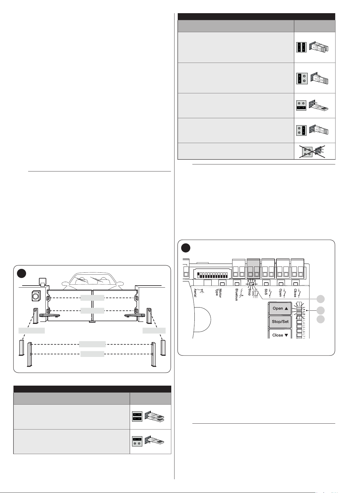
9.1.2 STOP input
STOP is the input that causes immediate stoppage of the
manoeuvre followed by its brief reversal. Devices with output
featuring normally open “NO” and normally closed “NC”
contacts, as well as devices with 8.2 kΩ xed resistor output,
such as sensitive edges, can be connected to this input.
As with the BlueBUS, the control unit recognises the type of
device connected to the STOP input during the learning phase
(see the “Learning of other devices” paragraph); subsequently
the control unit gives a STOP command when it detects a
variation with respect to the recognised status.
Multiple devices, even of different types, can be connected to
the STOP input if suitable arrangements are made:
– Any number of NO devices can be connected to each other
in parallel.
– Any number of NC devices can be connected to each other
in series.
– Two devices with 8.2 kΩ xed resistor output can be connected
in parallel; if there are more than 2 devices then they must all
be connected in cascade, with a single 8.2 kΩ terminating
resistor.
– It is possible to combine two NO and NC contacts by placing
them in parallel, while also mounting a 8.2 kΩ resistor in series
with the NC contact (this also allows for combining 3 devices:
NA, NC and 8.2 kΩ).
If the STOP input is used to connect devices with
a
safety functions, only those devices with 8.2 kΩ
xed resistor guarantee Category 3 safety against
faults in accordance with the EN 13849-1 standard.
PHOTOCELL ADDRESSES
Photocell
FOTO 1 (PHOTO 1)
Internal photocell h = 50 cm with activation
both during closing (stops and reverses the
movement) and during opening (stops and
restarts when the photocell disengages)
FOTO 1 II (PHOTO 1 II)
Internal photocell h = 100 cm with activation
both during closing (stops and reverses the
movement) and during opening (stops and
restarts when the photocell disengages)
FOTO 2 (PHOTO 2)
Internal photocell triggered during the
opening phase (stops and reverses the
gate’s movement)
FOTO 2 II (PHOTO 2 II)
Internal photocell triggered during the
opening phase (stops and reverses the
gate’s movement)
FOTO 3 (PHOTO 3)
CONFIGURATION NOT ALLOWED
At the end of the installation procedure, or after
m
Position of the
jumpers
photocells or other devices have been removed,
the learning procedure must be carried out (see
paragraph “Device learning“).
9.1.3 Photocells
To allow the control unit to recognise the devices connected
through the “BlueBUS” system, these devices must be
addressed.
This operation can be carried out by correctly positioning
the electrical jumper present in each device (also refer to
the instruction manual of each device). Shown below is an
addressing diagram for photocells, based on their type.
56
FOTO II
FOTO
FOTO 2 II FOTO 2
FOTO 1 II
FOTO 1
Table 12
PHOTOCELL ADDRESSES
Photocell
FOTO (PHOTO)
External photocell h = 50 activated during
the closing phase (stops and reverses the
gate’s movement)
FOTO II (PHOTO II)
External photocell h = 100 activated during
the closing phase (stops and reverses the
gate’s movement)
Position of the
jumpers
9.1.4 Learning of other devices
Normally the learning of devices connected to “BlueBUS” and
the “STOP” input takes place during the installation stage;
however, if new devices are added or old ones removed, the
learning process can be redone.
57
Bluebus
1 2 3 4 5 6 7 8 9
10 11 12
To do this:
1. simultaneously press and hold the
g
buttons
2. release the buttons when LEDs “L1” and “L2” start
ashing quickly (after roughly 3 seconds)
3. wait a few seconds until the control unit has completed the
device learning phase
4. once this phase terminates, the “Stop” (S) LED must be lit
and LEDs “L1” and “L2” must switch off (LEDs “L3” and
“L4” could start ashing).
After having added or removed devices, the
m
automation test must be carried out again as
specied in the “Testing” paragraph.
CloseOpenSbSStop
f
S
L1
L2
and
28 – ENGLISH

9.2 CONNECTING AN SM-TYPE RADIO RECEIVER
The control unit has a slot for mounting radio receivers with SM
connector (optional accessories), which can be used to remotely
control the control unit through transmitters that intervene on the
unit’s inputs.
Before installing a receiver, disconnect the power
f
supply to the control unit.
To install a receiver (“Figure 58”):
1. remove the cover of the control unit’s containment box
2. insert the receiver (A) in the appropriate slot (B) on the
control unit’s electronic board
3. put the cover of the control unit’s containment box back
on.
At this stage, the control unit can be powered again.
58
A
B
C
“Table 13” and “Table 14” show the “Receiver outputs” and the
“Control unit inputs” associated with each.
Table 13
SMXI / SMXIS OR OXI / OXIFM / OXIT / OXITFM IN MODE 1 OR MODE
2
Receiver output Control unit input
Output No. 1
Output No. 2
Output No. 3
Output No. 4
“SbS” (Step-by-Step) command
“Partial opening 1” command
“Open” command
“Close” command
OXI / OXIFM /OXIT / OXITFM IN MODE 2 EXTENDED
No. Command Description
1 Step-by-Step
2 Partial opening 1
3 Open
4 Close
5 Stop
Condominium
6
Step-by-Step
High priority Step-
7
by-Step
8 Partial open 2
9 Partial open 3
Opens and locks
10
the automation
Closes and locks
11
the automation
12 Lock automation
Release
13
automation
On Timer
14
Courtesy light
On-Off
15
Courtesy light
For further information, consult the specic manual
l
“SbS” (Step-by-Step) command
“Partial opening 1” command
“Open” command
“Close” command
Stops the manoeuvre
Command in condominium mode
Commands also with the automation
locked or the commands enabled
Partial opening (the M2 gate leaf
opens to 1/2 the full length)
Partial open (the two gate leaves
open to 1/2 the full length)
Triggers an opening manoeuvre
and, once this terminates, locks the
automation; the control unit will not
accept any command other than
“High priority Step-by-Step” and
automation “Unlock”, or (only from
Oview) the following commands:
“Unlock and close” and “Unlock and
open”
Triggers a closing manoeuvre and,
once this terminates, locks the
automation; the control unit will not
accept any command other than
“High priority Step-by-Step” and
automation “Unlock”, or (only from
Oview) the following commands:
“Unlock and close” and “Unlock and
open”
Triggers the stoppage of the
manoeuvre and locks the
automation; the control unit will not
accept any command other than
“High priority Step-by-Step” and
automation “Unlock”, or (only from
Oview) the following commands:
“Unlock and close” and “Unlock and
open”
Triggers unlocking of the automation
and restores normal operation
The courtesy light output switches on
with timer-based switching off
The courtesy light output switches on
and off in Step-by-step mode
of the receiver.
Table 14
ENGLISH – 29

9.3 CONNECTING AND INSTALLING THE BACKUP BATTERY
The electrical connection of the battery to the
f
control unit must be made only after completing
all the installation and programming stages, as the
battery is an emergency power supply.
Before installing a back-up battery, disconnect the
f
power supply to the control unit.
To install and connect the battery:
1. remove the cover (A)
2. lift the control unit (B) of the gearmotor
3. slide the battery (C) into its housing
59
A
4. insert the relative connector (E) in the housing (A) on the
control unit.
60
E
D
B
C
30 – ENGLISH

9.4 CONNECTING THE EXTERNAL UNLOCKING SYSTEM KIO
Kio must be connected to the gearmotor that drives
a
the leaf that starts moving rst (when the gate is
closed).
For the connection, proceed as follows:
1. remove the cover (A) and the plastic casing (B)
61
A
3. insert the steel cable (D) before the screw (C) and then
through the hole of pin (E)
4. lock the cable in place by tightening the pin (F)
63
D
C
FE
5. hook up the spring (G) by its two ends
64
B
2. insert the pin (C) through the unlocking shaft hole
62
C
G
6. thread the other end of the cable through the hole located
on the lower part of the gearmotor
65
7. connect the cable to Kio, by referring to the respective
instruction manual.
ENGLISH – 31
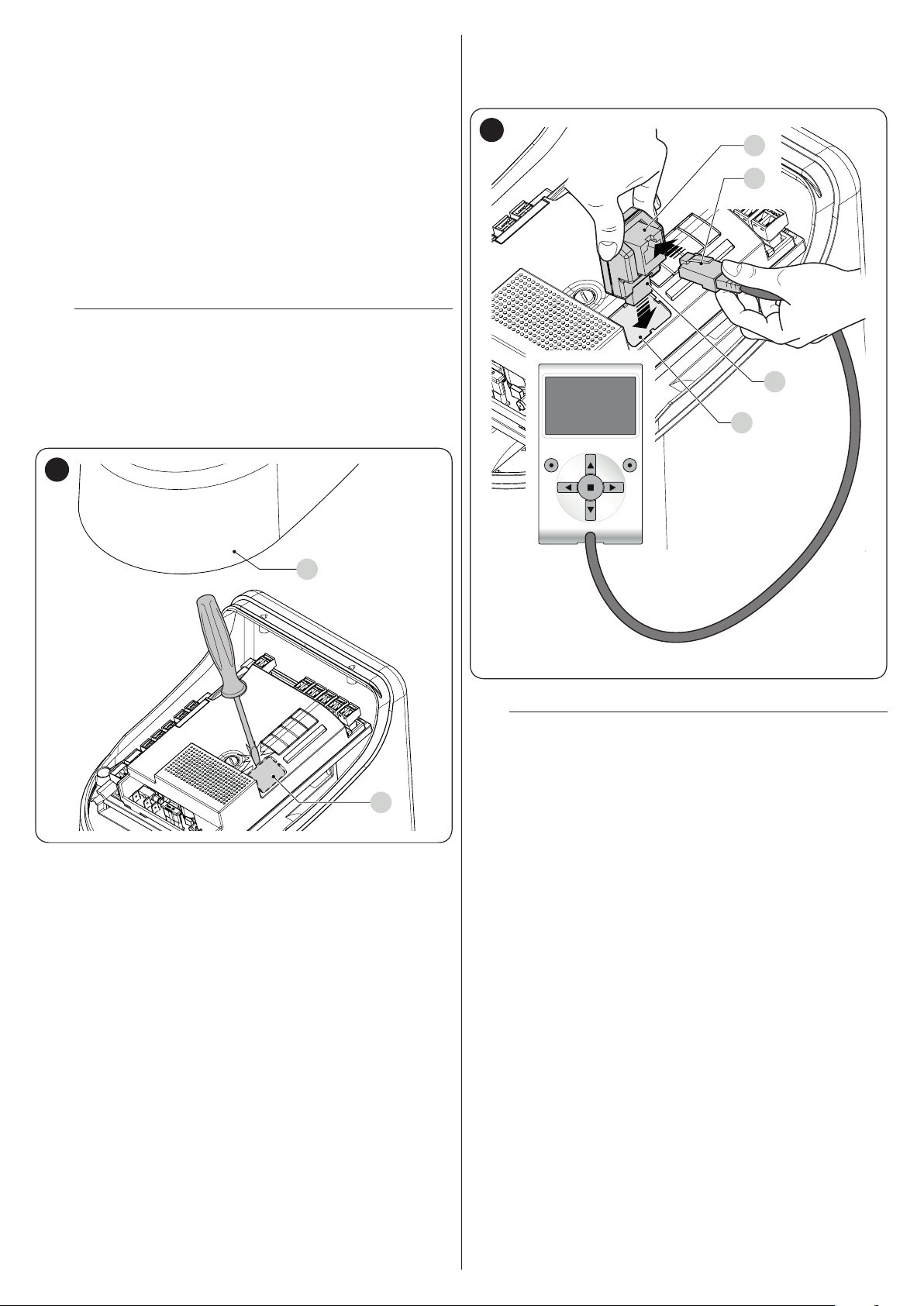
9.5 CONNECTING THE OVIEW PROGRAMMER
The “Oview” programming unit can be connected to the control
unit.
This unit allows for rapidly and fully programming the functions,
adjusting the parameters, updating the control unit rmware,
running the diagnostics to detect any malfunctions and
performing routine maintenance.
The “Oview” allows for operating on the control unit at a
maximum distance of roughly 100 m. If several control units are
networked with each other in a “BusT4” network, by connecting
the “Oview” to one of these units, it is possible to view on the
display all the networked control units (up to a maximum 16
units).
The “Oview” unit can also be left connected to the control unit
during normal operation of the automation, so that the user can
send commands using a specic menu.
Before connecting the IBT4N interface, it is
a
necessary to disconnect the control unit from the
power supply.
To install the interface:
1. remove the cover (A)
2. remove the plastic pre-cut element (B) and check that
there are no burrs
66
3. place the interface (C) in the appropriate slot (D) on the
control unit’s electronic board
4. insert the cable (E) in the appropriate slot (F) on the
interface.
67
F
E
C
D
A
At this stage, the control unit can be powered again.
For further information, consult the specic
l
manuals of the connected devices.
B
32 – ENGLISH

9.6 CONNECTING THE SOLEMYO SOLAR ENERGY SYSTEM
When the automation is powered by the “Solemyo”
f
system, IT MUST NOT BE POWERED by the
electricity grid at the same time.
68
For information on the “Solemyo” system, consult
l
the relevant instruction manual.
To connect the “Solemyo” system:
1. remove the cover (A)
2. insert the relative connector (C) in the housing (B) on the
control unit.
A
C
B
ENGLISH – 33

10
9 PRODUCT MAINTENANCE
The automation must be subjected to regular maintenance
to keep its safety level constant and guarantee long-lasting
operation; to this aim, HYKE has a manoeuvre counter and
maintenance warning system; refer to the ““Maintenance
notice” function” paragraph.
a
To carry out maintenance on the gearmotor:
1. Schedule maintenance interventions within maximum 6
2. disconnect all power supplies, including any back-up
3. check for any deterioration in the materials making up the
4. check the state of wear of moving parts: pinion, rack and
5. connect the power supplies again and run all the tests
PRODUCT MAINTENANCE
Maintenance must be carried out strictly in
compliance with the safety provisions provided in
this manual and in accordance with the laws and
regulations in force.
months or after maximum 20.000 manoeuvres from the
previous maintenance intervention
batteries
automation, with special emphasis on erosion or oxidation
of the structural parts; replace any parts that are not to
standard
all gate leaf components; replace any worn parts
and checks described in the “Testing” paragraph.
11
10 PRODUCT DISPOSAL
l
As with the installation, only qualied personnel must dismantle
the product at the end of its life.
This product is composed of different types of materials. Some
of these materials can be recycled; others must be disposed of.
Please enquire about the recycling or disposal systems in place
in your local area for this type of product.
a
l
PRODUCT DISPOSAL
This product is an integral part of the operator and
must therefore be disposed of with it.
WARNING
Some parts of the product may contain polluting or
dangerous substances. If not disposed of correctly,
these substances may have a damaging effect on
the environment and human health.
As indicated by the symbol shown
here, this product must not been
disposed of with household
waste. Separate the waste for
disposal and recycling, following
the methods stipulated by local
regulations, or return the product
to the seller when purchasing a
new product.
WARNING
a
Local regulations may impose heavy penalties if
this product is not disposed of in compliance with
the law.
34 – ENGLISH

12
11 TECHNICAL SPECIFICATIONS
l
TECHNICAL SPECIFICATIONS
All technical specications stated in this section refer to an ambient temperature of 20°C (± 5°C). Nice S.p.A.
reserves the right to apply modications to the product at any time when deemed necessary, without altering
its functions and intended use.
TECHNICAL SPECIFICATIONS
Description Technical specication
HK7024 HK7224 HK7024HS HK7224HS
Electromechanical gearmotor for
automatic gate and door systems with
Product type
Peak torque [corresponding to the ability to
develop a force capable of moving the leaf]
Nominal torque [corresponding to the ability
to develop a force capable of keeping the
leaf moving]
No-load speed (the control unit allow for
programming 6 speeds roughly equal to:
100, 85, 70, 55, 45, 30%)
Maximum frequency of operating cycles (at
nominal torque)*
Maximum continuous operating time (at
nominal torque)**
Application limits
Durability
Power supply HYKE 230Va (±10%) 50/60 Hz 24Vc (±10%)
Emergency power supply
Solar panel power supply
Maximum power draw at nominal torque
Maximum current draw
Power draw in “Stand-by-All” mode with
power supply from PS124 or SYKCE kit
(including OXI receiver)
Warning light output***
Electric lock output*** One 12 Va max 15 VA electric lock
Gate open indicator output***
BLUEBUS output
direct-current motor, epicyclic gear
reducer and mechanical unlocking
mechanism. Incorporated control unit and
OXI radio receiver
500 Nm
120 Nm
1,5 rpm 2 rpm 1,5 rpm 2 rpm
40 cycles/hour
7 minutes
The product can be
used on gates with
leaves weighing
up to 330 kg or for
lengths up to 3,5 m
Estimated between 150.000 cycles and 500.000 cycles, depending on the conditions
specied in the “Product durability” paragraph.
With optional accessory PS124 -
Conguration for SYKCE kit 300 W 140 W
1,5 A (3 A for version HK7024K/V1) 6 A for maximum 2 s
Below 30 mW -
One LUCYB warning light (12 Vc, 21 W)
lamp
One 24 V lamp maximum 4 W (the output
voltage can vary between -30 and +50%,
the output can also control small relays)
One output with maximum load of 15
Bluebus units
(maximum 6 pairs of photocells, e.g.
EPMB or EPLB, plus 2 pairs of photocells
addressed as opening devices plus
maximum 4 EDSB or ETPB control
devices)
The product can be
used on gates with
leaves weighing
up to 270 kg or for
lengths up to 3 m
Electromechanical gearmaotor for
automatic gate and door systems with
direct-current motor, epicyclic gear
reducer and mechanical unlocking
mechanism.
The product can be
used on gates with
leaves weighing
up to 330 kg or for
lengths up to 3,5 m
-
-
-
-
The product can be
used on gates with
leaves weighing
up to 270 kg or for
lengths up to 3 m
Table 15
ENGLISH – 35

TECHNICAL SPECIFICATIONS
Description Technical specication
HK7024 HK7224 HK7024HS HK7224HS
For normally closed or normally open
contacts or for 8.2 kΩ xed resistor
STOP input
contacts with self-learning (any variation
from the memorised status triggers the
STOP command)
For normally open contacts (closing of
Sbs input
the contact triggers the STEP-BY-STEP
command)
OPEN input
CLOSE input
Radio connector
Radio ANTENNA input
For normally open contacts (closing of the
contact triggers the OPEN command)
For normally open contacts (closing of the
contact triggers the CLOSE command)
SM connector for SMXI, OXI and OXIFM
receivers
50 Ω for RG58-type cable or similar -
-
-
-
8 ON-OFF functions and 8 adjustable
Programmable functions
functions (see “Level 1 programming
-
(ON-OFF)” paragraph)
Self-learning of the devices connected to
the BlueBus output
Self-learning of the type of “STOP” device
(Normally Open, Normally Closed contact
Self-learning functions
or 8.2 kΩ resistor)
Self-learning of the gate path and
-
automatic calculation of the slowdown
and partial opening points.
Self-learning of the operation with one or
two motors.
Assembly
Operating temperature
Use in highly acid, saline or potentially
explosive atmosphere
Protection rating
Dimensions (mm)
Weight (kg)
Vertical, with a dedicated xing plate
-20°C ÷ 55°C(at low temperatures, the gearmotor’s efciency decreases)
NO
IP 54 (with container intact)
210x290xh230h
10,5 kg 9,5 kg
* Frequency of cycles at the maximum temperature: 25 cycles/hour
** Maximum continuous cycle time at the maximum temperature: 8 minutes
*** The “Warning light” and “Electric lock” outputs can be programmed with other functions (see paragraph “Level 1
programming (ON-OFF)“), or paragraph “Connecting the Oview programmer“). The electrical characteristics of the
outputs can be adapted on the basis of the type of chosen function: warning light function: 12 Vc, 21 W max lamp; electric
lock function: 12 Va, 15 VA max; other outputs (all types): 1 lamp or relay 24 Vc (–30 e +50%), 4 W max.
36 – ENGLISH

13
EU Declaration of Conformity
Note - The contents of this declaration correspond to declarations in the ofcial document deposited at the registered ofces of Nice S.p.a. and in particular to the last revision available before
printing this manual. The text herein has been re-edited for ed
Number:
Manufacturer’s Name:
Address:
Authorized Person to constitute
technical documentation:
Type of product:
Model/Type:
Accessories:
The undersigned Roberto Griffa, in the role of Chief Executive Ofcer, declares under his sole responsibility that the product described above complies with the provisions
laid down in the following directives:
•
The product also complies with the following directives according to the requirements envisaged for “partly completed machiner
•
It is hereby stated that the relevant technical documentation has been compiled in accordance with annex VII B of Directive 2006/42/EC and that the following essential
requirements have been fullled: 1.1.1 - 1.1.2 - 1.1.3 - 1.2.1 - 1.2.6 - 1.5.1 - 1.5.2 -
The manufacturer undertakes to transmit to the national authorities, in response to a reasoned request, the relevant information on the “ partly completed machinery “, while
maintaining full rights to the related intellectual property.
Should the “ partly completed machinery” be put into service in a European country with an ofcial language other than that used in this declaration, the importer is obliged
to arrange for the relative translation to accompany this declaration.
The “partly completed machinery” must not be used until the nal machine in which it is incorporated is in turn declared as compliant, if applicable, with the provisions of
directive 2006/42/EC.
The product also complies with the following standards:
EN 60335-1:2012+A11:2014, EN 62233:2008, EN 60335-2-103:2015
Oderzo,
12 CONFORMITY
CONFORMITY
and declaration of incorporation of “partly completed machinery”
itorial purposes. A copy of the original declaration can be requested from Nice S.p.a. (TV) I.
334/HYKE Rev: 4 Language: EN
Nice s.p.a.
Via Callalta 1, 31046 Oderzo (TV) Italy
Electromechanical gear motor “HYKE” with incorporated control unit
Nice s.p.a.
HK7024, HK7224, HK7024HS, HK7224HS
Refer to the catalog
Directive 2014/30/EU (EMC), according to the following harmonized standards: EN 61000-6-2:2005, EN 61000-6-3:2007+A1:2011
Directive 2006/42/EC of the EUROPEAN PARLIAMENT AND COUNCIL of 17 May 2006 related to machinery and amending the Directive 95/16/EC (recast).
1.5.5 - 1.5.6 - 1.5.7- 1.5.8 - 1.5.10 - 1.5.11
05/09/2017
y” (Annex II, part 1, section B):
ENGLISH – 37

NOTES
38 – ENGLISH

&
INSTRUCTIONS AND WARNINGS FOR THE USER
Before using the automation for the rst time, ask the installer to
explain the origin of any residual risks and take a few minutes
to read this instruction manual and warnings for the user given
to you by the installer. Store the manual for future reference and
hand it to the new owner when transferring the automation.
WARNING!
a
Your automation is a machine that faithfully executes
commands imparted by the user. Negligence and
improper use may lead to dangerous situations:
– do not manoeuvre the gate if there are people, animals
or objects within its range of operation
– it is strictly forbidden to touch parts of the automation
while the gate or door is moving
– the photocells are not a safety device but only an
auxiliary aid to safety. They are built using highly reliable
technology but, in extreme conditions, may malfunction
or even become defective. In certain cases, the defect
may not be clearly evident. For these reasons, it is
important to follow all the instructions given in this
manual when using the automation
– periodically check that the photocells work properly.
IT IS STRICTLY FORBIDDEN to transit through the
a
gate while it is closing! It is only possible to transit
through the gate when it is fully open and the leaves
are at a standstill.
CHILDREN
a
An automation system guarantees a high degree
of safety. With its detection systems, it can control
and guarantee the gate’s movement in the presence
of people or objects. It is nonetheless advisable to
forbid children from playing near the automation
and not to leave remote controls near them to
prevent any unwanted activation of the system. The
automation is not a toy!
The product is not intended for use by persons,
including children, with limited physical, sensory
or mental capacities, or who lack experience or
knowledge, unless supervised or trained in the use
of the product by a person responsible for their
safety.
Anomalies: if the automation shows any signs of anomalous
behaviour, disconnect the power supply to the system and
manually unlock the motor (see instructions at the end of the
chapter) to manoeuvre the gate manually. Do not attempt any
repairs personally but contact your trusted installer.
Do not modify the system or the programming
l
and adjustment parameters of the control unit:
your installer is exclusively responsible for these
operations.
Failure or lack of power supply: while waiting for the installer
to intervene or the electricity to be restored, if the system
is not equipped with back-up batteries, the automation can
nonetheless be used by manually unlocking the motor (consult
the instructions at the end of the chapter) and moving the gate
leaf manually.
Safety devices out of order: the automation can also be used
when one or more safety devices are defective or out of order.
The gate can be operated in the “hold-to-run” mode in the
following way:
1. send a command to operate the gate using a transmitter
or key selector, etc. If everything works normally, the gate
will move regularly, otherwise the warning light will ash a
few times and the manoeuvre will not start (the number of
ashes depends on the reason for which the manoeuvre
cannot start)
2. in this case, within 3 seconds press the control again and
hold it down
3. after roughly 2 seconds, the gate will complete the
requested manoeuvre in “Hold-to-run” mode, in other
words, it will continue to move so long as the control is
held down.
If the safety devices are out of order, have the
m
system repaired as soon as possible by a qualied
technician.
The test, periodic maintenance and any repairs must be
documented by the person carrying out the work and the
documents must be stored by the owner of the automation. The
only interventions the user may carry out periodically include
cleaning of the photocell glass components (use a soft and
slightly damp cloth) and removing any leaves or stones that may
obstruct the automation.
Before carrying out any maintenance operations,
m
the user of the automation must manually unlock
the motor to prevent anyone from accidentally
triggering the gate’s movement (consult the
instructions at the end of the chapter).
Maintenance: in order to ensure constant levels of safety and
the longest useful life for the automation, routine maintenance
must be carried out (at least every 6 months).
Only qualied personnel is authorised to carry out
l
checks, maintenance operations and repairs.
Disposal: at the end of its useful life, the automation must be
dismantled by qualied personnel and the materials must be
recycled or disposed of in compliance with the local regulations
in force.
Replacing the remote control battery: if your remote control
appears to be working poorly after some time, or stops working
altogether, it may simply depend on at batteries (depending
on how much the device is used, the batteries may last from
several months to over a year). You will notice this by the fact
that the indicator light signalling the transmission fails to light up,
is weak or lights up only for a short time. Before contacting the
installer, try replacing the battery with that of another transmitter
that works properly: if the anomaly is resolved, simply replace
the at battery with one of the same type.
&
ENGLISH – 39

Unlocking and manual movement
The gate can only be unlocked once the leaf has
a
come to a standstill.
To unlock the device:
1. insert the key (A) and turn it clockwise by 90°
2. turn the lever (B) by 90° anti-clockwise which, by effect of
a spring, has come out of its housing
69
90°
A
90°
B
&
3. the gate leaf can now be moved manually to the desired
position.
To lock the device:
1. turn the lever (B) by 90° until it lies in the vertical position
2. push the lever until it slots into its housing
3. turn the key (A) by 90° anti-clockwise
4. remove the key.
40 – ENGLISH
&

NOTES
ENGLISH – 41

NOTES
42 – ENGLISH

NOTES
ENGLISH – 43

Nice SpA
Via Callalta, 1
31046 Oderzo TV Italy
info@niceforyou.com
IDV0670A00EN_01-10-2018
www.niceforyou.com
 Loading...