


FLOR
EN - Instructions and warnings for
installation and use
IT - Istruzioni ed avvertenze per
l’installazione e l’uso
FR - Instructions et avertissements
pour l’installation et l’utilisation
ES - Instrucciones y advertencias
para la instalación y el uso
DE - Installierungs-und Gebrauchs-
anleitungen und Hinweise
PL - Instrukcje i ostrzeżenia do
instalacji i użytkowania
NL - Aanwijzingen en aanbevelingen
voor installatie en gebruik
Receiver
FLOXR family


EN
English - 1
Original instructions
ENGLISH
1 – PRODUCT DESCRIPTION AND
INTENDED USE
This receiver is part of the “Flor” series by Nice spa. This
series of receivers is intended for use on the Control units
featured in automated systems for gates, garage doors and
road barriers. Any other use is to be considered incorrect
and forbidden! The manufacturer shall not be held liable
for damage due to improper use of the product other
than that specified in this manual.
2 – PRODUCT TECHNICAL
SPECIFICATIONS
• For all models
– The receiver handles “Flor” type radio encoding with a
variable code (rolling-code) and also recognises the C-
Code encoding of the Opera series for the basic functions.
– These models have 1 or 2 relays with clean contact output;
they can therefore be used with any type of Control unit.
3 – PRODUCT INSTALLATION
• For models with “NICE” connector
These models are connected to the Control system by
inserting their connector into the specific one featured on the
Control unit. Important! – Before connecting or removing
the receiver, cut off the electricity supply to the Control
unit.
In addition, you should install the aerial provided, connecting
it to the purpose-provided terminals on the Control unit.
WARNINGS
WORKING IN SAFETY!
CAUTION! – For personal safety it is important to
observe these instructions.
CAUTION! – Warning - Important safety instructions:
keep these instructions in a safe place.
CAUTION! – All product installation, connection,
programming and maintenance operations must be
performed exclusively by a qualified and skilled te chnician.
Observe the following warnings:
– Never make any modifications to part of the product
other than those specified in this manual. Unauthorised operations can be the source of hazards and
malfunctions. The manufacturer declines all liability for
damage caused by makeshift modifications to the
product.
– Keep this manual in a safe place to enable future product
maintenance and programming operations.
– The product packaging material must be disposed of in full
ob servance of current local legislation governing waste
disposal.
2 - English
EN
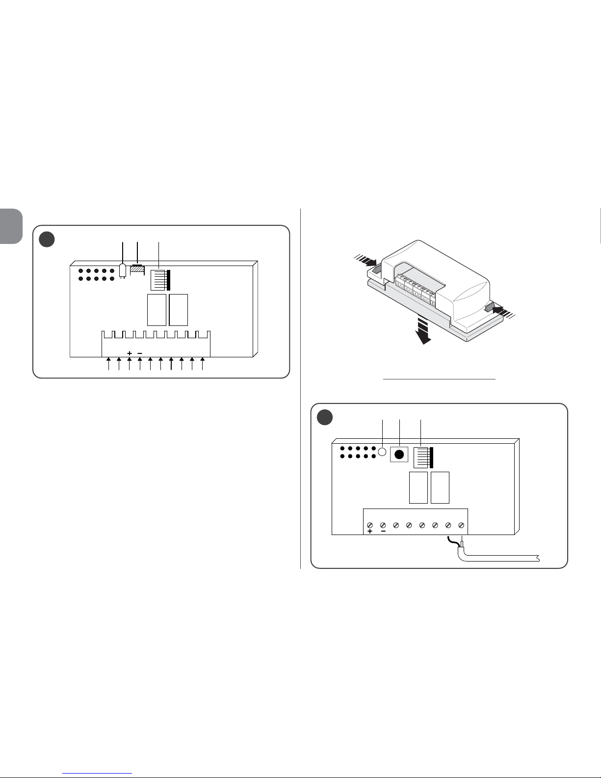
Fig. 1 illustrates the electrical connections on the connector:
A = not used
B = electricity supply
C = relay 1 output
D = relay 2 output
E = aerial
• For models with universal connection
These models with a terminal board make universal use possible; they can be wall-mounted using screws (not provided)
or using the adhesive on the bottom of the box.
––– Electrical connections
–––
Make the connections as follows (fig. 2):
2
12345612
L1 P1 BM
1
1
2
AERIAL
Opening of the box for receivers with universal connection:
L1 P1 BM
ABCDE
1
relay 1 relay 2
relay 1 relay 2
EN
English - 3
1-2 POWER SUPPLY 12/24 V direct or alternating.
3-4 1
st
RELAY OUTPUT: clean contact of a normally open
relay.
5-6 2
nd
RELAY OUTPUT: clean contact of a normally open
relay (only on receivers with 2 channels).
1-2 AERIAL: aerial signal input.
––– Installing an external aerial
–––
If the aerial provided is in an unfavourable position and the
radio signal is weak, we recommend you improve reception
by replacing the aerial through the installation of an external
one (mod. ABF or ABFKIT). The new aerial should be positioned as high as possible and above any metallic or reinforced concrete structures in the area.
If necessary, use a coaxial cable with an impedance of 50
ohm (for example, the RG58 low-loss cable). Important! –
To reduce signal dispersion, use the shortest possible cable
(it should not exceed 10 m in length).
– Aerial connection
(only for models with universal con-
nection): connect the aerial cable to terminal 1 and 2 (fig.
2): terminal 1 = sheath; terminal 2 = core.
– Aerial connection for models with Nice connector
:
connect the aerial cable to the purpose-provided terminals
on the control unit.
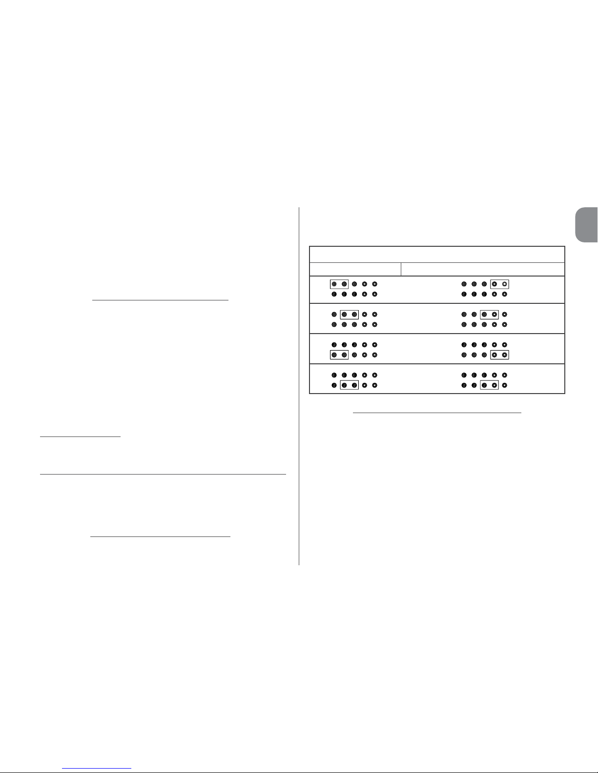
• For all models:
––– Relay selection on channels –––
Each receiver is designed to recognise all 4 keys on the
transmitter. This is possible thanks to the association of the
output relays with the desired key, through an electric jumper
which should be inserted in the purpose-provided connectors: see Table 1.
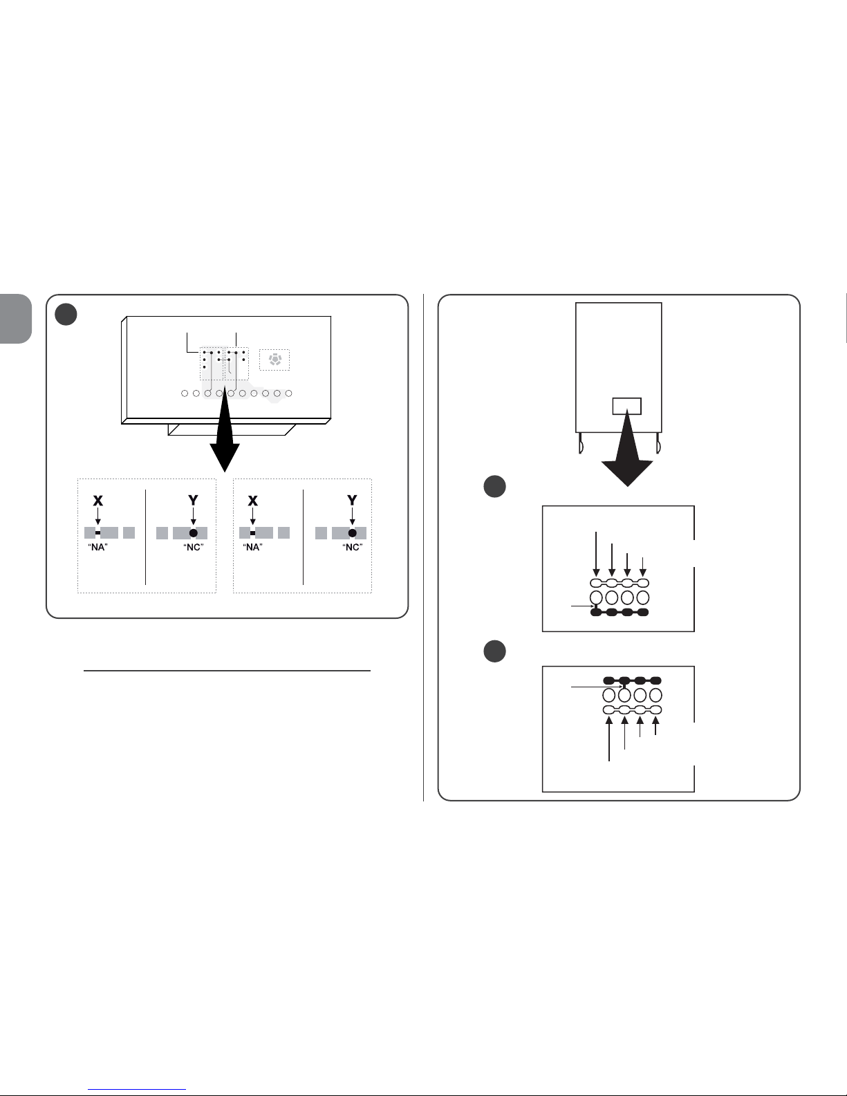
––– How to obtain “NC” type contacts
–––
The outputs are operated by 2 relays with a “NO” (normally
open) type contact. If you want to achieve a “NC” (normally
closed) contact, proceed as follows:
01. Disconnect the electrical power supply to the receiver.
02. Remove the board carefully and turn it over: the side
with the welding should be facing you.
03. On the side with the welding, carry out the following
steps (fig. 3):
– Cut the section of line at point “X”.
– Using a drop of tin, join the spots at points “Y”.
Note – these changes can be made on one relay or on both,
depending on your requirements.
Key: 1
TABLE 1
Relay 1 Output Relay 2 Output (where present)
Key: 2
Key: 3
Key: 4
4 - English
EN
––– Selecting the channel on the transmitter –––
On the FLOR series of transmitters, the association of the
transmitter key with the receiver channel can be modified:
• For key 1 of the transmitter, proceed as shown in fig. 4a:
cut the track that associates key 1 with channel 1 and connect one of the other spots on the right with a drop of tin, to
obtain the association with channel 2, 3 or 4.
• For key 2 of the transmitter, proceed as shown in fig. 4b.
4a
4b
1stCHANNEL
2
nd
CHANNEL
1stCHANNEL
2ndCHANNEL
3rdCHANNEL
4thCHANNEL
2ndKEY
1
st
KEY
CUT
CUT
4thCHANNEL
3
NA NC
3rdCHANNEL
relay 2 relay 1
relay 2 relay 1

EN
English - 5
4 – PROGRAMMING
Warnings
The programming featured in this chapter requires the
use of key P1 and of LED L1 on the receiver (fig. 1). To
indicate the status of the activity under way, the LED
emits a specific number of flashes for a specific amount
of time. To find out the meaning of these indications,
please consult Table 2.
To facilitate programming, you ca use the BUPC and OBox
programmers.
TABLE 2
SIGNALS EMITTED BY LED L1 ON THE RECEIVER
–– SLOW 1/2 second FLASH ––
1 ✺ =
The code received is not among those authorised.
2 ✺ = Recognition time over without success.*
3 ✺ = Recognition successfully completed (code authorised).
4 ✺ = The code is already in the list of those authorised.
5 ✺ = The list is empty (no code).
6 ✺ = The list is full (there is no room for any more codes).
7 ✺ = The deletion of a non-existent code has been requested.
8 ✺ = Different codes were received during the recognition phase.
9 ✺ = Password entered.
* Note
- If the software memor
y lock is activated
, the 2nd flash is longer
than the 1st one
- If the software memor
y lock is deactivated
the two flashes are
the same.
–– FAST 1/4 second FLASH ––
• During initialisation
:
1 ✺ = A BM60 memory is present
2 ✺ = A BM250 memory is present
3 ✺ = A BM1000 memory is present
4 ✺ = The memory has codes entered which are not from the
Flor version
5 ✺ = An error was detected during memory reading
• During operation
:
1 ✺ = The code received is a “copy”; only “original” codes are
valid.
3 ✺ = The code is not inside the codes window, but it has been
resynchronised.
4 ✺ = The code is not inside the codes window and resynchroni-
sation is locked.
5 ✺ = The code is not inside the codes window and resynchroni-
sation is not possible.
The receiver is fitted standard with the BM250 memory
which can store up to 63 codes; when the receiver is powered, it displays the type of memory used with various flashes of LED L1 (fig. 1), see Table 2.
The usable memories are as follows:
– memory BM60 = 16 storable codes
– memory BM250 = 63 storable codes
– memory BM1000 = 255 storable codes
The memory contains all the transmitter codes stor
ed; to
obtain maximum safety and avoid the accidental storage of
foreign codes, you can lock the code recognition function
(see paragraph 6.1 - Locking the memory).

6 - English
EN
4.1 – Storage of a transmitter
A transmitter (its code) can be stored in the memory of a
receiver in two ways:
- rapid mode
- standard mode
4.1.1 – Rapid mode
This is the quickest mode to use, but it is not extremely safe
because during the code storage operation, the receiver
may acquire a different signal from another transmitter within
its operating range and store it by mistake. We recommend
you assess this risk before selecting your storage mode.
01. Press and keep key P1 (fig. 1) on the receiver pressed:
LED L1 is turned on;
02. Press any key on the transmitter and transmit the code
until LED L1 on the receiver is turned off;
03. Then release the key on the transmitter: LED L1 is
turned back on and the receiver is ready for another
task;
04. To store the other transmitters, repeat the process from
step 02. When storage is complete, release key P1 on
the receiver.
4.1.2 – Standard mode
01. Press and release key P1 (fig. 1) on the receiver; LED L1
is turned on for 5 sec.;
02. During these 5 sec. transmit the code until LED L1 on
the receiver is turned off;
03. Then release the key on the transmitter and wait for 1
sec.;
04. Press and keep any key on the transmitter pressed, to
send the code, until LED L1 on the receiver is turned off;
the LED will emit three flashes to indicate that the
process was successful;
If this does not happen, then repeat the process.
05. To store the other transmitters, repeat the process from
step 01.
N.B. – To avoid the storage in the receiver of a signal casually transmitted by a transmitter which has nothing to do with
the automated system in question, the BM memory can be
locked; please see paragraph 5.4.
4.1.3 – Storage of a transmitter using the procedure ‘in
the vicinity of the receiver’ (with a transmitter
already stored)
A NEW transmitter can be stored in the memory of the
receiver without intervening directly on the key of this receiver, but simply by operating in its range of reception. To implement this procedure, you need to have an OLD transmitter at
hand, which has already been stored and is operational.
Warnings:
• The procedure must be performed while operating in
the range of reception of the receiver (10-20 m from
the receiver).
• Repeat the entire process for each transmitter you
wish to store.
01. On the NEW transmitter, keep key... pressed for at least
5 seconds. and then release it.
02. On the OLD transmitter, press key ....three times and
then release it.

EN
English - 7
03. On the NEW transmitter, press the same key as in step
01 once and then release it.
4.2 – Total deletion of the receiver memory
WARNING! – When you do this, the software lock function is
also deleted and the "Timer" is automatically set to 3 sec.
01. Press and keep key P1 (fig. 1) on the receiver pressed:
after 3 sec. LED L1 is turned off;
02. When LED L1 starts flashing again, on the 3rd flash,
release key P1 and wait approximately 3 sec.;
03. As soon as LED L1 is turned back on, press key P1 and
release it as soon as the LED is turned off.
Depending on the type of memory fitted on the receiver, the
process may take a few seconds. During this phase, LED L1
flashes quickly, followed by 5 slow flashes to indicate that
total deletion was successful and that the memory is empty.
If this does not happen, then repeat the process.
4.3 – Deletion of a single transmitter from the
receiver memory
01. Press and keep key P1 (fig. 1) on the receiver pressed
for approximately 3 sec.: LED L1 is turned off, then
release the key;
02. Press and keep any key on the transmitter pressed, to
send the code, until LED L1 on the receiver is turned off;
03. Release the key on the transmitter and wait 1 sec.;
04. Press and keep any key on the transmitter pressed, to
confirm: LED L1 emits 1 flash to indicate that the code
has been deleted.
If this does not happen, then repeat the process from
step 01.
5 – OTHER FUNCTIONS
Usually the output relay function is momentary: i.e. the relays
are activated a few seconds after a key is pressed on the
transmitter (delay due to the code recognition time) and the
activation ends 300 mS after the receipt of the last valid
code.
Below is a description of other special functions, available for
the output relays.
IMPORTANT! – To activate the special functions, you
will need to use a small drop of tin, see fig. 5.
5.1 – STEP-STEP Function
The relay is activated by pressing a key on the transmitter
and it remains activated even after the key has been
released; the key needs to be pressed again to deactivate
the relay.
5.2 – TIMER Function
The relay is activated by pressing a key on the transmitter
and it remains activated until the programmed amount of
time lapses. The countdown of the programmed time
restarts every time the key on the transmitter is pressed
again and it can be stopped early by keeping the same key
pressed for at least 3 sec.
5.2.1 – Programming the timer
To program the timer, you need to activate the TIMER func-

8 - English
EN
tion (electric jumper 3, fig. 5). If - during programming - you
prefer the relays not to be activated, you will need to remove
the electric jumper for the channel selection temporarily.
Programming
01. Press and keep key 1 of an operational transmitter
pressed;
02. Within 3 sec., also press and keep key P1 (fig. 1) on the
receiver pressed and then release the key on the transmitter;
03. Keep key P1 pressed for the time you wish to program
(max 2 h 30’) and then release key P1.
At this stage, the desired time has been stored and
remains valid until a new programming is performed.
Note – During the timer programming phase, the normal
operation of the receiver is inhibited.
5.3 – BURGLAR ALARM Function
Activate this function to obtain the combined function of
relays 1 and 2. Press key 1 on the transmitter to obtain the
"Step-step" function on relay 1 of the receiver (this function is
suitable for enabling/disabling a burglar alarm).
Concurrently, relay 2 (where present) performs 1 brief activation when relay 1 switches from OFF to ON and 2 brief activations when relay 1 switches from ON to OFF.
This way, relay 2 can be connected to an optical or acoustic
signal which can be used to notify that a burglar alarm has
been enabled/disabled.
Note – If this function is activated, relay 2 maintains its normal operation associated with key 2 of the transmitter.
NA NC
5
NO JUMPER all channels momentary
JUMPER 1 1 step-step....2, 3, 4 momentary
JUMPER 2 1, 2 step-step....3, 4 momentary
JUMPER 3 1 timer....2, 3, 4 momentary
JUMPER 4 1 + 2 burglar alarm....3, 4 momentary
JUMPER 5 all channels step-step
relay 2 relay 1
EN
English - 9
5.4 – Locking the memory
There are two ways to do this:
– Locking the memory via the hardwar
e (paragraph 5.4.1)
– Locking the memory via the softwar
e (paragraph 5.4.2)
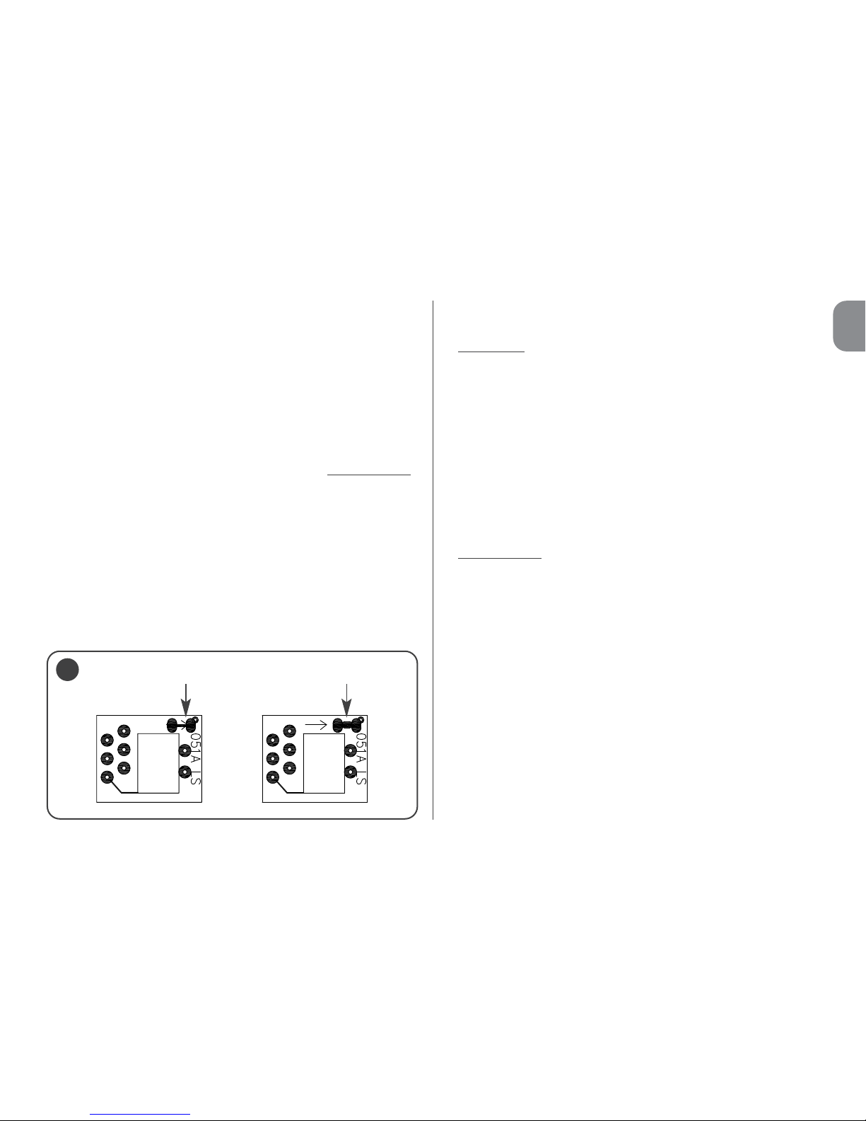
5.4.1 – Activating the memory lock: hardware
This locking mode is very simple to perform but it is not very
safe. Indeed, it can easily be cancelled by outsiders.
IMPORTANT! – The memory enabling/disabling operations must be performed with the receiver not powered
.
After inserting the desired transmitter codes, proceed as
shown in fig. 6: cut (X) the track indicated by the arrow.
If you later wish to insert other codes, proceed as shown in
fig. 6: join (Y) the two spots with a drop of tin.
5.4.2 – Activating and deactivating the memory lock:
software
This is a safer way to activate the memory lock. In fact, you
need to have a transmitter that has already been stored in
the receiver to deactivate it.
• Activating
the memory lock
01. Press and immediately release key P1 (fig. 1) on the
receiver;
02. Wait for LED L1 to flash twice, indicating the time is up
(approx. 5 sec.) and at the 2nd flash, press key P1 and
then release it when LED L1 is turned off.
Next, LED L1 emits two flashes: if the second flash lasts
longer than the first, this means that the memory lock has
been activated. If the flashes last the same, this means that
the memory lock has not been activated. In this case, repeat
the process from step 01.
• Deactivating
the memory lock
To deactivate the memory lock, you need to have a transmitter that has already been stored. Proceed as follows:
01. Press and immediately release key P1 (fig. 1) on the
receiver: LED L1 is turned on for 5 sec.;
02. During these 5 sec. press any key on the transmitter, to
transmit the code, until LED L1 is turned off;
03. Then release the key on the transmitter and wait for 1
sec.;
04. Press and keep any key on the transmitter pressed, to
send the code: LED L1 will emit 4 flashes to indicate that
that code is already on the list;
05. During the 4th flash, press key P1 and release it when
LED L1 is turned off.
Next, LED L1 will emit 2 flashes for the same amount of time,
which means that the memory lock is no longer activated.
X Y
6

10 - English
EN
If this does not happen, then repeat the process from step 01.
The memory lock can also be activated in a safer and more
controlled way: using a “PASSWORD”: this method can only
be implemented with the use of the BUPC and OBox programmers.

EN
English - 11
DISPOSING OF THE PRODUCT
This product is an integral part of the automation system,
and should therefore be disposed of together with it.
As for the installation operations, even at the end of this
product's life span, the dismantling operations must be carried out by qualified experts.
This product is made up of various types of materials: some
can be recycled while others need to be disposed of. Find
out about the recycling or disposal systems envisaged by
your local regulations for this product category.
Important! – parts of the product could contain pollutants or
hazardous substances which, if released into the environment,
could cause harmful effects to the environment itself as well as
to human health.
As indicated by the symbol opposite,
throwing away this product as domestic
waste is strictly forbidden. So dispose of it
as differentiated waste, in accordance with
your local regulations, or return the product to the retailer when you purchase a
new equivalent product.
Important! – the local applicable regulations may envisage
heavy sanctions in the event of illegal disposal of this product.
PRODUCT TECHNICAL SPECIFICATIONS
WARNINGS: • All technical specifications are referred to a
room temperature of 20°C (± 5°C). • Nice S.p.a. reserves the
right to make any changes deemed necessary to the product at any time while maintaining the same functions and
intended use. • The operating distance between transmitters
and receivers (range) is heavily influenced by other devices
operating in the vicinity at the same frequency (for example
headphones, alarm systems, etc.). In such cases, Nice cannot provide any guarantee as regards the effective range of
its devices.
• Decoding: “FloR”
• Power supply: 12-24 V direct or alternating. Limits from
10 to 28 V
• Power consumption when idle: 16 mA at 24 VDC
• Power consumption with 2 relays active: 80 mA at 24
VDC
• Reception frequency: 433.92 MHz
• Sensitivity: better than 0.5 μV
• No. of relays: 1 or 2 depending on the model
• Normally open relay contact: max 0.5 A and 50 V SELV
• Operating temp.: from –20° C to +55° C
• Protection rating: IP 30
• Dimensions and weight: 58 mm x 86 mm x H 22 mm; 55 g

12 - English
EN
EC DECLARATION OF CONFORMITY
Note – This Declaration of Conformity gathers the contents of all the individual declarations of conformity of each product mentioned herein; it is updated to the date of publication of this manual and was re-adapted for publishing purposes.
A copy of the original declaration for each product can be requested from Nice S.p.a. (TV) I.
Number: 201/FLOX Revision: 2
The undersigned Luigi Paro, as Managing Director, declares on his own responsibility that the product:
Name of manufacturer: NICE s.p.a.
Address: Via Pezza Alta 13, Z.I. Rustignè, 31046 Oderzo (TV) Italy
Type: 433.92MHz receiver for the remote control of automated gates, doors, blinds, awnings,
shutters and similar applications
Models: FLOX1, FLOX2, FLOXI, FLOXB2, FLOXI2, FLOXM, FLOXM220
Accessories:
Compliant with the essential requirements provided for in Art. 3 of the following EC directive, for the use for which the
products are intended:
• 1999/5/EC DIRECTIVE 1999/5/EC OF THE EUROPEAN PARLIAMENT AND OF THE COUNCIL of 9 March 1999 concerning radio equipment and terminal telecommunications units and the reciprocal acknowledgment of their compliance
In accordance with the following harmonized standards health protection: EN 50371:2002; electrical safety:
EN 60950-1:2006;
electromagnetic compatibility: EN 301 489-1V1.8.1:2008; EN 301 489-3V1.4.1:2002; radio spectrum:
EN 300 220-2 V2.1.2:2007
Oderzo, 20
th
March 2009 Luigi Paro (Managing Director)
D0865 Rev2
 Loading...