

Page 1

PROGRAMMABLE AC POWER SOURCE
DP Series
INSTRUCTION MANUAL
NF Corporation
Page 2

Page 3

DA00027113-001
PROGRAMMABLE AC POWER SOURCE
DP Series
INSTRUCTION MANUAL
Page 4

Page 5
⎯⎯⎯ Preface ⎯⎯⎯
Thank you for purchasing our Programmable AC Power Source DP Series.
For safe and correct use of the electrical product, please first read "Safety Precautions"
page.
Alert symbols in this manual
This manual uses the following alert symbols. The instructions by these alert symbols shall be
carefully obeyed to ensure equipment operator's safety and prevent damage to equipment.
WARNING
Equipment handling could result in death or serious injury. This symbol contains information
to avoid such risk.
CAUTION
on the next
Equipment handling could result in minor or moderate injury, or property damage. This
symbol contains information to avoid such risk.
This manual consists of the following chapters.
If it is the first time for you to use this product, start with "1. Outline."
1. Outline
2. Preparation before Use
3. Basic operation
4. Advanced Operation
5. Description of Screen and Menu
6. Remote Control
7. Options
8. Troubleshooting
is suspected.
9. Maintenance
10. Specifications
: Explains the overview, configuration, and features of this product.
: Explains the preparations carried out before installation or operation.
: Explains the component names and basic operations.
: Explains the operations more extensively.
: Explains the screen configuration and menu composition.
: Explains the remote control via communication interface.
: Explains the available options.
: Explains the remedies when an error message is displayed, or when a failure
: Explains the methods of storage, repackaging, transportation, and maintenance.
: Provides the list of specifications of functions and performance.
DP Series
i
Page 6

⎯⎯⎯ Safety Precautions ⎯⎯⎯
For safe use, ensure to obey the following warnings and considerations.
We are not responsible for damage resulting from failure to obey these warnings and considerations.
This product is an insulation Class I device (with a protective conductor terminal) complying with
the JIS and IEC standards.
Ensure you obey the instructions in this instruction manual.
This instruction manual contains instructions for safe operation and use of this product.
Before using the product, please read this manual first.
All the warning items contained in this instruction manual are intended for preventing risks that may
lead to serious accidents. Ensure to obey them.
Ensure to ground.
This product uses a line filter, which may cause electric shock if the product is not grounded.
To prevent electric shock accidents, connect it to an earth ground so that ground resistance is 100Ω
or less.
Check the power supply voltage.
This product operates on the power supply voltage specified in "2.4 Grounding and Power
Connect
distribution board conforms to the power supply voltage rating of the product.
If you notice anything strange
If this product produces smoke, unusual odor, or strange sound, immediately cut the power to the
product and stop using it.
Should you encounter any anomaly like above, immediately contact us or our agent. Never use it
until the repair is completed.
Do not use in a gaseous atmosphere.
This may pose a risk of explosion or other.
Do not remove the cover.
This product has high-voltage portions inside. Never remove the cover.
When inspection into the inside of the product is needed, never allow anybody to touch the innards
except our certified service engineers.
Do not modify the product.
Never modify the product. Modification to the product may pose a new risk. We may refuse the
repair of a modified product at fault.
ions". Before connecting the product to a power supply, make sure that the voltage of
ii
PROGRAMMABLE AC POWER SOURCE
Page 7
Prevention of electric shock by output voltage
The maximum output of this product is ± 440 V. Be careful to avoid electric shock. Directly
touching the output or changing the cable connection while the output is on may cause electric
shock.
This product weights over 18 kg.
Do not carry it alone, or you may suffer physical injury.
Safety symbols
The following shows the general definitions of the safety symbols used on the product main unit and
in the instruction manual.
Refer to the instruction manual
This notifies the user of potential hazards and indicates that he/she must refer to the
instruction manual.
Electric shock hazard
This indicates that an electric shock may occur under specific conditions.
Protection conductor terminal
This indicates that the terminal needs to be grounded in order to prevent electric shock
accidents.
Before operating the equipment, ensure to connect this terminal to an earth ground by
the "Electric Facilities Technical Standards Type D (100Ω or less)" or a higher standard.
WARNING
Warning
This contains information to avoid risks in equipment handling that could
result in loss of life or bodily injury (e.g., electric shock).
CAUTION
Caution
This contains information to avoid damage to the equipment in equipment
handling.
Other symbol
Chassis
This indicates that the terminal (or external conductor for a connector) is connected to
the chassis.
Request about disposal
For environmental preservation, pay attention to the followings when you dispose of this product.
The backlight of the LCD contains mercury.
This product shall be disposed of through an appropriate industrial waste disposer.
DP Series
iii
Page 8

Table of Contents
Page
Preface ........................................................................................................................................ i
Safety Precautions.......................................................................................................................ii
List of Figures ............................................................................................................................. x
List of Tables .............................................................................................................................xii
1. Ou
2. P
3. B
tline ................................................................................................................................... 1
1.1 Ov
1.2 S
1.3 F
reparation before Use ......................................................................................................... 7
2.1 C
2.2 A
2.3 C
2.4 Groundi
2.5 Output
2.5.1 S
2.5.2 P
2.5.3 Mul
2.5.4 P
2.6 H
2.7 S
2.8 C
asic Operation ................................................................................................................... 31
3.1 C
3.1.1 F
3.1.2 R
3.1.3 C
3.2 P
3.2.1 B
3.2.2 S
3.2.3 P
3.2.4 S
3.2.5 T
3.2.6 C
3.2.7 P
3.3 B
3.3.1 C
3.3.2 Ite
erview ...................................................................................................................... 2
eries Line-up and Polyphase System Configuration .................................................. 2
eatures ....................................................................................................................... 4
heck before Use......................................................................................................... 8
bout Installation Environment..................................................................................... 8
autions during Moving and Transportation............................................................... 11
ng and Power Connections ........................................................................... 13
and System Cable Connection ....................................................................... 17
ingle-phase Model ............................................................................................ 17
olyphase Model................................................................................................. 19
ti-phase Model............................................................................................... 21
olyphase System............................................................................................... 22
ow to Tilt Control Panel............................................................................................ 26
imple Operation Check ............................................................................................ 27
alibration .................................................................................................................. 30
omponent Name ...................................................................................................... 32
ront.................................................................................................................... 32
ear .................................................................................................................... 34
ontrol Panel ...................................................................................................... 36
ower On/Off.............................................................................................................. 37
efore Turning on the Power .............................................................................. 37
et the Output Phase Mode (Multi-phase model Only)....................................... 38
ower On ............................................................................................................ 38
creen Display and Operations at Starting Up ................................................... 39
he Settings Loaded after Startup ...................................................................... 39
hecking the Rated Power ................................................................................. 40
ower Off ............................................................................................................ 40
asic Key Operations ................................................................................................. 41
hanging the Output Function (Continuous Output/Sequence/Simulation) ..... 41
m Selection ..................................................................................................... 41
iv
PROGRAMMABLE AC POWER SOURCE
Page 9

3.3.3 Using Soft-keys ................................................................................................... 42
3.3.4 C
3.3.5 E
3.3.6 E
3.3.7 U
3.4 U
3.4.1 S
3.4.2 S
3.4.3 S
3.4.4 S
3.4.5 S
3.4.6 S
3.4.7 S
3.4.8 T
3.4.9 U
3.4.10 S
3.4.11 E
3.4.12 C
3.4.13 Sw
losing Windows................................................................................................. 43
ntering Values (Numerical Entry Box)............................................................... 44
ntering Strings (Character String Entry Box) .................................................... 44
sing Shortcut Operations (SHIFT Key) ............................................................. 46
sing the Continuous Function .................................................................................. 47
etting the AC/DC Mode and the Signal Source ................................................ 47
etting the Output Range.................................................................................... 50
etting Waveforms .............................................................................................. 51
etting the Output Voltage (Single-phase Output) .............................................. 53
etting the Output Voltage (Polyphase Output) .................................................. 54
etting the Output Frequency ............................................................................. 56
etting the Output On/Off Phase ........................................................................ 56
urning the Output On or Off .............................................................................. 57
sing the Measurement Function ....................................................................... 58
witching the Display Format (RMS/AVG/Peak) of the Measured Value............ 59
nlarge Display Letters for the Measured Value ................................................ 61
learing the Output Current Peak-hold Value..................................................... 63
itching the Target Phase of which the Measured Values are Displayed
(Polyphase Output) ............................................................................................. 65
4. A
dvanced Operation............................................................................................................ 67
4.1 U
4.2 U
sing Limiter, Setting Limiter ..................................................................................... 68
4.1.1 U
4.1.2 U
4.1.3 U
4.1.4 U
4.1.5 A
se Peak Current Limiter .................................................................................... 68
sing RMS Current Limiter ................................................................................. 70
sing Voltage Setting Range Limit...................................................................... 71
sing Frequency Setting Range Limit................................................................. 73
bout Wattage Limiter......................................................................................... 74
sing Sequence Function .......................................................................................... 75
4.2.1 B
4.2.2 P
4.2.3 E
4.2.4 P
4.2.5 E
asics.................................................................................................................. 75
arameters of Sequence Function...................................................................... 78
xample of Output Using Sequence Function .................................................... 81
rocess Flow in a Step ....................................................................................... 81
dit a Sequence.................................................................................................. 83
4.2.6 Load a Sequence ................................................................................................ 85
4.2.7 E
4.2.8 S
4.2.9 C
4.2.10 S
4.2.11 S
4.2.12 S
4.3 U
4.3.1 B
xecute a Sequence ........................................................................................... 89
ave a Sequence ................................................................................................ 92
lear/Rename Sequence .................................................................................... 96
et so as the Sequence Function is Selected at Power-on .............................. 100
equence Control by External Control.............................................................. 101
creen Overview ............................................................................................... 101
sing Power Fluctuation Testing (Simulation) Function........................................... 103
asics................................................................................................................ 103
DP Series
v
Page 10

4.3.2 Simulation Function Parameters ....................................................................... 104
4.3.3 Ou
4.3.4 P
4.3.5 E
4.3.6 Loadi
4.3.7 E
4.3.8 S
4.3.9 C
4.3.10 S
4.3.11 S
4.3.12 S
4.4 Me
4.4.1 H
4.4.2 B
4.4.3 Me
4.5 Me
4.5.1 In
4.5.2 B
4.5.3 Me
4.5.4 Me
4.6 U
4.7 Ou
4.7.1 B
4.7.2 A
4.7.3 A
4.7.4 T
4.7.5 Ou
4.8 U
4.8.1 B
4.8.2 A
4.8.3 S
4.8.4 S
4.9 U
4.10 U
4.11 U
4.12 U
4.13 U
4.14 A
4.15 U
4.16 U
4.17 S
4.17.1 U
tput Examples Using Simulation Function.................................................... 106
rocess Flow in a Step ..................................................................................... 108
diting Simulation ............................................................................................. 108
ng a Simulation.......................................................................................... 111
xecuting Simulation......................................................................................... 114
aving Simulation ............................................................................................. 116
lear/Rename Simulation ................................................................................. 120
et so as the Simulation Function is Selected at Power-on ............................. 124
imulation Control by External Control ............................................................. 125
creen Overview ............................................................................................... 125
asuring Harmonic Current ................................................................................... 127
armonic current............................................................................................... 127
asics................................................................................................................ 128
asured Value Display Method ...................................................................... 128
asuring Inrush Current......................................................................................... 129
rush Current ................................................................................................... 129
asics................................................................................................................ 130
asurement Method ....................................................................................... 130
asurement Tips............................................................................................. 131
sing Clipped Sine Wave......................................................................................... 131
tputting Arbitrary Waveform ................................................................................. 134
asics................................................................................................................ 134
rbitrary Waveform Creation Procedure ........................................................... 135
rbitrary Waveform Creation Example.............................................................. 135
ransferring Arbitrary Waveform....................................................................... 135
tputting Arbitrary Waveform.......................................................................... 138
sing Memory Function ........................................................................................... 139
asic Setting Memory ....................................................................................... 140
rbitrary Waveform Memory ............................................................................. 147
equence Memory ............................................................................................ 151
imulation Memory ........................................................................................... 152
sing USB Memory Function ................................................................................... 153
sing Monitor Function ............................................................................................ 154
sing Remote Sensing Function.............................................................................. 157
sing AGC Function................................................................................................. 160
sing Autocal Function............................................................................................. 163
djusting DC Offset.................................................................................................. 167
sing for Unbalanced Polyphase Output ................................................................. 169
sing as DC Power Supply ...................................................................................... 171
etting Voltage using External DC Input Signal ....................................................... 172
sing External Signal in AC-VCA Mode ........................................................... 172
vi
PROGRAMMABLE AC POWER SOURCE
Page 11

4.17.2 Using External Signal in DC-VCA Mode ........................................................... 174
4.18 C
4.19 Sy
4.20 A
4.21 T
4.22 E
4.23 Using t
4.24 P
4.25 K
4.26 B
4.27 C
4.28 R
5. D
5.1 S
5.2 Menu C
6. R
6.1 C
6.2 R
7. Op
7.1 A
7.2 S
7.3 E
7.4 R
7.5 S
7.6 GP
7.7 R
7.8 R
8. T
ontrol Using External Control Function .................................................................. 176
nchronizing the Output Frequency with the Power Line or the External Signal ... 181
mplifying the External Signal Input (Optional)........................................................ 183
urning the Output On or Off Rapidly....................................................................... 184
nabling Automatic Output-On at Power-On............................................................ 186
he Emission CO2 Calculator.......................................................................... 187
ower Unit Energization Setting (Using Under the Restricted Rated Power) .......... 189
ey Lock................................................................................................................... 191
eep ......................................................................................................................... 191
hanging the Background Color and the Contrast of the Screen ............................ 192
estoring to the Factory Default Setting (Reset) ..................................................... 193
escription of Screen and Menu ....................................................................................... 197
creen Configuration................................................................................................ 198
5.1.1 S
5.1.2 Me
5.1.3 Ou
5.1.4 W
tatus Icon ........................................................................................................ 199
asured Value Display Items ......................................................................... 200
tput Setting Display Items............................................................................. 201
arning and Error Display ................................................................................ 201
omposition.................................................................................................... 202
5.2.1 Menus of
5.2.2 Menus of
5.2.3 Menus of
5.2.4 Menus of
5.2.5 S
ystem Menus................................................................................................... 205
the Continuous Function ................................................................... 202
the Sequence Function ..................................................................... 203
the Simulation Function ..................................................................... 204
the Memory Function......................................................................... 204
emote Control ................................................................................................................. 207
ommunication Interface ......................................................................................... 208
6.1.1 U
6.1.2 R
6.1.3 GP
SB ................................................................................................................... 208
S232 ............................................................................................................... 210
IB (Optional) ................................................................................................. 212
emote/Local State Switching.................................................................................. 214
6.2.1 R
6.2.2 L
emote State .................................................................................................... 214
ocal State ........................................................................................................ 214
tions .............................................................................................................................. 215
GC and Measurement Extensions ......................................................................... 216
equence and Simulation Functions ........................................................................ 216
xternal Signal Input ................................................................................................ 216
emote Controller .................................................................................................... 216
ystem Cable (for Polyphase System)..................................................................... 217
IB ......................................................................................................................... 217
ack-Mount Adapter................................................................................................. 218
eplacement Air Filter .............................................................................................. 218
roubleshooting................................................................................................................. 221
DP Series
vii
Page 12

8.1 Error Messages and Error Handling ......................................................................... 222
8.1.1 E
8.1.2 If
8.1.3 If
8.1.4 P
8.1.5 E
8.2 W
9. Mai
ntenance...................................................................................................................... 235
9.1 P
9.2 D
9.3 S
9.4 C
pecifications .................................................................................................................... 241
10. S
10.1 Ou
10.2 Output
10.3 A
10.4 S
10.5 A
10.6 D
10.7 O
10.8 D
10.9 P
10.10 W
10.11 Me
10.12 P
10.13 C
10.14 S
10.15 R
10.16 A
10.17 A
10.18 S
10.19 S
10.20 Clipp
10.21 A
10.22 E
10.22.1 E
10.22.2 V
10.22.3 E
10.23 General
10.24 Me
10.25 S
10.26 E
rror Message Screen ...................................................................................... 222
An Error Message is Displayed...................................................................... 222
An Error Occurs Repeatedly .......................................................................... 223
rotection Operation Types .............................................................................. 224
rror Message List ............................................................................................ 225
hen a Failure is Suspected ................................................................................... 229
reface ..................................................................................................................... 236
aily Maintenance .................................................................................................... 236
torage, Repackaging, Transportation ..................................................................... 239
hecking Firmware Version ..................................................................................... 239
tput Function........................................................................................................ 242
Range ........................................................................................................... 242
C/DC Mode ............................................................................................................ 243
ignal Source ........................................................................................................... 244
C Output................................................................................................................. 245
C Output ................................................................................................................ 247
utput Voltage Stability ............................................................................................ 248
istortion of Output Voltage Waveform .................................................................... 248
ower Input .............................................................................................................. 249
ithstand Voltage and Insulation Resistance .......................................................... 249
asurement Function............................................................................................. 250
ower Unit Energization Setting............................................................................... 254
urrent Limiter.......................................................................................................... 255
etting Range Limit Function ................................................................................... 256
emote Sensing ....................................................................................................... 257
GC (Optional)......................................................................................................... 258
utocal (Output Voltage Compensation).................................................................. 258
equence (Optional) ................................................................................................ 259
imulation (Optional)................................................................................................ 260
ed Sine Wave................................................................................................... 261
rbitrary Wave.......................................................................................................... 261
xternal Signal Input ................................................................................................ 262
xternal Synchronous Signal Input (Signal Source SYNC only) ...................... 262
oltage Setting Signal Input (Signal Source VCA only) .................................... 262
xternal Signal Input (Optional, only EXT and ADD)........................................ 263
Function...................................................................................................... 263
mory Function...................................................................................................... 264
elf-diagnosis/Protection Function........................................................................... 265
xternal Control I/O.................................................................................................. 266
viii
PROGRAMMABLE AC POWER SOURCE
Page 13

10.27 External Interface ..................................................................................................... 267
10.28 U
10.29 W
10.30 Op
10.31 E
10.32 Op
10.33 Ou
SB Memory Interface ............................................................................................. 267
aveform Monitor Output ........................................................................................ 268
eration Environment ............................................................................................ 269
xternals, Weight, and Terminal Block..................................................................... 270
tion ....................................................................................................................... 271
tline Dimensional Drawing ................................................................................... 272
Index....................................................................................................................................... 276
DP Series
ix
Page 14

Figures and Tables
List
of Figures
Page
Figure 1-1 Model N
Figure 2-1 How to Use the Adjuster Foot .............................................................................. 10
Figure 2-2 Terminal Panel Arrangement of
Figure 3-1 Component N
Figure 3-2 Component N
Figure 3-3 Component Nam
Figure 3-4 The Self Check Screen to be Displayed w
in Other Output Phase Mode than before ............................................................ 39
Figure 3-5 The Rated Power Icon ......................................................................................... 40
Figure 3-6 The Root Menu .................................................................................................... 41
Figure 3-7 The Example of a Selection Box.......................................................................... 42
Figure 3-8 The Example of a Data List Box .......................................................................... 42
Figure 3-9 Soft-key Function ................................................................................................. 43
Figure 3-10 The Example of the Window with the [Close] Button ........................................... 43
Figure 3-11 The Example of the Window with the [OK]/[Cancel] Button................................. 44
Figure 3-12 The Numerical Entry Box ..................................................................................... 44
Figure 3-13 Character String Entry Box .................................................................................. 45
Figure 3-14 The Normal View (left) an
Figure 4-1 Step-control Parameters and
Figure 4-2 Step B
Figure 4-3 Stop Phase..........................................................................................................
Figure 4-4 Example of
Figure 4-5 Process Flow i
Figure 4-6 Branch Operation/Stop Operation ........................................................................ 82
Figure 4-7 Sequence E
Figure 4-8 Sequence Control View (
Figure 4-9 Sequence Control View (Output On S
Figure 4-10 Sequence Control View (
Figure 4-11 Simulation F
Figure 4-12 Voltage Dip S
Figure 4-13 Voltage Change S
Figure 4-14 Process Flow through
Figure 4-15 Stop Operation ................................................................................................... 108
Figure 4-16 Simulati
Figure 4-17 Simulation Control View (
Figure 4-18 Simulation Control View (Output
aming System........................................................................................... 3
Multi-phase Model (Rear) .................................. 21
ame (Front) .................................................................................... 32
ame (Rear)..................................................................................... 34
e (Control Panel)....................................................................... 36
hen Starting the Unit in Other System or
d the Simple View Mode (right) ................................... 61
intra-Step Parameters ........................................... 76
ehavior....................................................................................................... 77
. 80
Sequence.......................................................................................... 81
n Sequence Step .......................................................................... 82
dit View........................................................................................... 102
Output Off State) ........................................................ 102
tate/Sequence in Execution) .................. 102
Output On State/Sequence Stopped) ......................... 103
unction Steps ................................................................................. 105
imulation Example........................................................................ 106
imulation Example................................................................. 107
Simulation Steps ............................................................ 108
on Edit View .......................................................................................... 126
Output Off State, Simulation Stopped) ...................... 126
On State, Simulation Running) ...................... 126
x
PROGRAMMABLE AC POWER SOURCE
Page 15

Figure 4-19 Simulation Control View (Output On State, Simulation Stopped) ...................... 127
Figure 4-20 Current Waveform Cont
Figure 4-21 Inrush C
urrent Example ..................................................................................... 129
aining Many Harmonic Components ............................ 127
Figure 4-22 Clipped Sine Wave............................................................................................. 131
Figure 4-23 USB Memory F
Figure 4-24 Sensing Input Term
older Structure ........................................................................... 153
inals in Multi-phase Model .................................................. 158
Figure 4-25 The Message Window to be Shown Before the Automatic Output-On After the
P
ower-On ........................................................................................................... 186
Figure 5-1 Component Name (Display A
Figure 5-2 Menu C
Figure 7-1 Remote Control
omposition ............................................................................................. 202
ler External View ....................................................................... 217
reas on the Screen) ............................................. 198
Figure 7-2 Front Grills ......................................................................................................... 219
Figure 8-1 Error Message S
Figure 10-1 Range of Ambient T
Figure 10-2 DP015S, DP030S, DP03
Figure 10-3 DP045S, DP045T, DP045M, D
Figure 10-4 DP075S, DP090S, DP090D
Figure 10-5 DP090M, DP105S, DP120S
creen Example ........................................................................ 222
emperature/Humidity .......................................................... 269
0D (Type 1 cabinet).................................................... 272
P060S, DP060D (Type 2 cabinet) ..................... 273
, DP090T (Type 3 cabinet)..................................... 274
, DP120D (Type 4 cabinet).................................... 275
DP Series
xi
Page 16

List of Tables
Page
Table 1-1 Series Line-up (Single-ph
Table 1-2 Series Line-up (Mul
Table 1-3 Polyphase System
Configuration List .................................................................... 4
ase Model, Polyphase Model) ....................................... 3
ti-phase Model) ....................................................................... 3
Table 2-1 List of Content........................................................................................................ 8
Table 2-2 Heat Value (Estimate at
Power Input 200 V, Rated Output).................................. 9
Table 2-3 Weight .................................................................................................................... 9
Table 2-4 Power Input Terminal ........................................................................................... 14
Table 2-5 Maximum Input Power/C
urrent and Power Input Cable....................................... 14
Table 2-6 Output Terminals ................................................................................................. 17
Table 2-7 Outlet List ............................................................................................................. 19
Table 3-1 Component N
Table 3-2 Component N
Table 3-3 Component Nam
ame (Front) .................................................................................... 33
ame (Rear)..................................................................................... 35
e (Control Panel)....................................................................... 36
Table 3-4 How the Rated Power Icon is Displayed Depending on the Power Unit
E
nergization Setting............................................................................................. 40
Table 3-5 Character String Entry List................................................................................... 45
Table 3-6 Shortcut Operations ............................................................................................. 46
Table 3-7 Description of the AC/DC Mode........................................................................... 47
Table 3-8 The Description of
Table 3-9 List of the Selectable Combinations of
Table 3-10 The Setting R
the Signal Source .................................................................. 47
the AC/DC Mode and the Signal Source 48
ange per Output Range ................................................................. 50
Table 3-11 Main Measurement Functions.............................................................................. 58
Table 3-12 The Measuring Mode for the Measured Values of
the Output Voltage and Output
Current ................................................................................................................. 59
Table 4-1 Wattage Limiter Value per P
Table 4-2 Parameters of
Sequence Function ...................................................................... 78
hase (Reference value, Unit: W)............................. 75
Table 4-3 Example of Editing Sequence.............................................................................. 81
Table 4-4 Simulation Function Parameters........................................................................ 104
Table 4-5 Simulation Function Step
Table 4-6 Voltage Dip Sim
ulation Edit Example ................................................................ 107
Table 4-7 Voltage Change Sim
s and Settable Step Parameters ................................ 105
ulation Edit Example ......................................................... 107
Table 4-8 Different Output Voltage Settings Depending on Clip Depth Setting Method.... 132
Table 4-9 Content Sav
ed in Sequence Memory ................................................................ 151
Table 4-10 Content Saved in Simulation Memory................................................................ 152
Table 4-11 Setting Range of DC Of
fset Adjustment Value .................................................. 167
Table 4-12 CONTROL I/O Pin Assignment.......................................................................... 177
Table 4-13 The Output Terminal I
mpedance (Reference Values in the Rear Output Terminal)
in the Output Off State when the Activation of the Output Relay is Disabled .... 184
Table 4-14 Setting Items to be Reset................................................................................... 193
Table 5-1 Component Name (D
isplay Areas on the Screen)............................................. 198
xii
PROGRAMMABLE AC POWER SOURCE
Page 17

Table 5-2 Status Icons ....................................................................................................... 199
Table 5-3 Measured Value Display Items .......................................................................... 200
Table 5-4 Output Setting Display Items ............................................................................. 201
Table 5-5 Menus of the C
Table 5-6 Menus of the S
Table 5-7 Menus of the S
Table 5-8 Menus of the Mem
Table 5-9 System
Menus ................................................................................................... 205
Table 7-1 Rack-Mount A
Table 7-2 Replacement Air F
Table 8-1 Description of the E
Table 8-2 Error Message Li
Table 8-3 Actions When a F
ontinuous Function .................................................................... 202
equence Function ...................................................................... 203
imulation Function...................................................................... 204
ory Function ......................................................................... 204
dapter Model Names ................................................................... 218
ilter Model Names ................................................................ 218
rror Message Screen .......................................................... 222
st............................................................................................. 225
ailure is Suspected ................................................................ 229
DP Series
xiii
Page 18

Page 19

1. Outline
1.1 Overview ····································································· 2
1.2 Series Line-up and Polyphase System Configuration· 2
1.3 Features ······································································ 4
DP Series
1
Page 20

1. Outline
1.1 Overview
The DP series offers a compact, lightweight, and highly-efficient power system, ranging from
single-phase 1.5 kVA to three-phase 36 kVA at a maximum. It also provides various interfaces such
as the external control input/output, communication interface, and remote controller (some of them
are optional) to address a wide variety of usage. You can configure several products of same
single-phase model to participate in a single-phase three-wire system or three-phase four-wire
system by using a System Cable (optional).
The AC output of DP series ranges from 0 to 310 V for voltage (phase voltage) and 1 to 550 Hz for
frequency, and the DC voltage output ranges from −440 V to +440 V. The maximum output current
(phase current) is 120 Arms continuous (single-phase 12 kVA, 100 V range), and if you use a
capacitor input type rectified load, you can output a peak value of 480 Apk at a maximum
(single-phase 12 kVA, 100 V range, crest factor of 4).
1.2 Series Line-up and Polyphase System Configuration
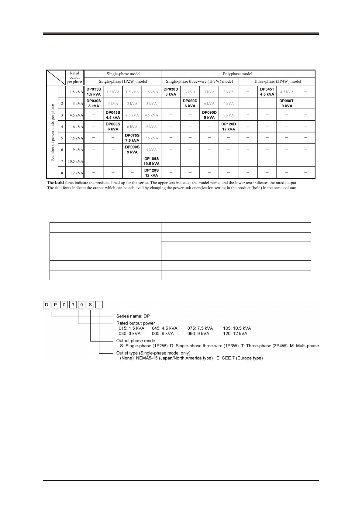
In the DP series, multiple models (single-phase model, polyphase model) are available with various
combinations of output capacity and output phase mode. The lineups of single-phase model and
polyphase model are listed in Table 1-1.
The D
(single-phase two-wire, single-phase three-wire, or three-phase four-wire) on a cabinet. When you
set the "phase mode setting switch" of the Multi-phase model and then turn on the power, the model
operates as single-phase model or polyphase model as shown in Table 1-2. The operation
speci
those of the single-phase model and polyphase model of the DP series shown in Table 1-2.
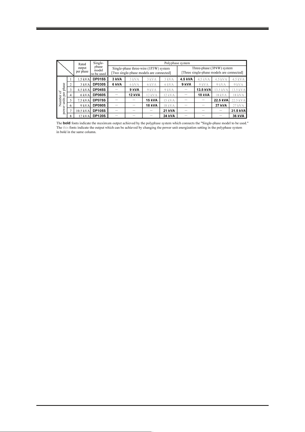
The m
F
optional System Cable to allow single-phase three-wire output or three-phase four-wire output,
respectively (polyphase system). The polyphase system configurations are listed in Table 1-3.
P series also offers the Multi-phase model which can switch the output phase mode
fication, performance specification, and manipulation method of the Multi-phase model follow
odel naming system of the DP series is shown in Figure 1–1.
or the single-phase model, you can connect two or three products of the same model using an
2
PROGRAMMABLE AC POWER SOURCE
Page 21
1.2 Series Line-up and Polyphase System Configuration
Table 1-1 Series Line-up (Single-phase Model, Polyphase Model)
Table 1-2 Series Line-up (Multi-phase Model)
Setting of phase mode setting switch DP045M DP090M
1φ2W (Single-phase two-wire output)
Operates as DP045S. Operates as DP090S.
Does not support the polyphase system connection
which uses the optional System Cable.
1φ3W (Single-phase three-wire output)
3φ4W (Three-phase four-wire output)
Operates as DP030D. Operates as DP060D.
Operates as DP045T. Operates as DP090T.
Figure 1-1 Model Naming System
DP Series
3
Page 22
1. Outline
Table 1-3 Polyphase System Configuration List
1.3 Features
Various interfaces to address a variety of usage
In addition to RS232, USB, and GPIB (optional) to use for the remote controlling from a computer
or sequencer, you can use a contact/TTL signal to turn the output on/off or switch the memory
without using a computer. The product also offers the status output for showing the device status
and the output which is synchronized with Sequence or Simulation (optional) step. With these
functions you can achieve various types of systemization and automatization. The AGC function
(optional) and Autocal function for calibrating the output voltage drop are also provided.
Variable current limiter
This function can limit the effective value and the positive/negative peak value of the output current
where the limiting value is variable. You can set the limiter so that the output is turned off when the
limited condition continues for a certain time.
Globally adjustable power inlet without restricted by the power supply environment
The DP series supports a wide range of power input from 100 V to 230 V. However, with the model
of which the output capacity is 6 kVA or more, the output power capacity will be limited when the
power input is 170 V or less.
Feature-rich measurement function
On the panel the product displays the effective value, peak value, average DC value, current
peak-hold value, and active/apparent power of the output voltage/current. Furthermore, the power
factor, crest factor, reactive power, and harmonic current are also measured and displayed by
additional options.
4
PROGRAMMABLE AC POWER SOURCE
Page 23

1.3 Features
Control Software included by default
You can perform the following operations by using Control Software included in the attached
CD-ROM:
• Operations same as those performed on the control panel
• Editing/transferring/exporting the arbitrary waveform data*
• Data logging (importing the measured values)
• Editing/exporting*/performing Sequence (When the option is embedded)
• Editing/exporting*/performing Simulation (When the option is embedded)
*Exporting the data to USB memory allows the data to be set to the DP series.
USB memory support
You can write/read the following data to/from a commercial USB memory stick:
• Basic setting
• Sequence
• Simulation
• Arbitrary waveform
Restriction of CO
emission (= power usage) and the display of CO2 emission (= power
2
usage) during operation
The efficiency is improved by about 27% compared to the linear amplifier method by adopting the
switching amplifier method. When the power output is low, the internal loss can be lowered by
reducing the number of power units being powered on. The function for calculating and displaying
the CO
emission from the internal loss or output power.
2
Options (partial)
Remote Controller
A remote controller with the numeric keypad, jog, and shuttle.
Sequence and simulation
These functions allow you to perform tests such as blackout, voltage rise, voltage drop, abrupt
phase change, and so on.
System Cable (for single-phase three-wire/three-phase connection)
Connects the products of the same single-phase model by this cable to configure a polyphase
output system.
DP Series
5
Page 24

1. Outline
6
PROGRAMMABLE AC POWER SOURCE
Page 25

2. Preparation before Use
2.1 Check before Use························································ 8
2.2 About Installation E
nvironment ··································· 8
2.3 Cautions during Moving and
2.4 Grounding and Power C
2.5 Output and System C
2.6 How to Tilt C
2.7 Simple Operation Check ··········································· 27
2.8 Calibration ································································· 30
ontrol Panel··········································· 26
able Connection ······················ 17
Transportation ············· 11
onnections ·························· 13
DP Series
7
Page 26
2. Preparation before Use
2.1 Check before Use
Check the safety.
To ensure equipment operator's safety, be sure to read the following sections of the instruction
manual at the beginning.
Safety Precautions (P
2.4 Grounding and Power Connections
Chec
k the appearance and contents.
If there is any problem, contact the seller (NF Corporation or our agent) from whom you purchased
the product.
Appearance check
Make sure that there is no damage or dent made during the transportation on the LCD screen,
keys, jog, or shuttle of the control panel, or rear connectors.
Contents (main unit and accessories) check
The contents are listed in Table 2-1. Make sure that all of the main unit and accessories are
i
ncluded.
age ii)
Table 2-1 List of Content
Content Quantity
Main unit Main unit 1
Instruction Manual 1
CD-ROM
Accessories
The GPIB option is built in the main unit.
Contents: Control Software for DP Series, LabVIEW Driver,
Instruction Manual (Remote Control), Control Software for
DP Series Instruction Manual
Power cable (3 m approx.) 1
1
2.2 About Installation Environment
To use safely and maintain the reliability, take the followings into consideration:
Install the product where the exhaust heat will not damage surroundings.
This product performs forced air cooling using a fan. Keep the front and rear, on which the air
inlet and outlet are located, away from the wall at least 50 cm to secure air circulation.
This product exhausts the heat from the air outlet on the rear. Do not place heat-sensitive
objects around the outlet.
If you install the product in a closed narrow room, air conditioning equipment is required. The
heat value of this product is shown in Table 2-2 (estimate at power input 200 V, rated output).
8
PROGRAMMABLE AC POWER SOURCE
Page 27

2.2 About Installation Environment
Table 2-2 Heat Value (Estimate at Power Input 200 V, Rated Output)
Model Rated output Heat value
DP015S 1.5 kVA 0.5 kW 430 kcal/h
DP030S 3 kVA 0.9 kW 780 kcal/h
DP045S 4.5 kVA 1.4 kW 1210 kcal/h
Single-phase
DP060S 6 kVA 1.8 kW 1550 kcal/h
DP075S 7.5 kVA 2.3 kW 1980 kcal/h
DP090S 9 kVA 2.7 kW 2320 kcal/h
DP105S 10.5 kVA 3.2 kW 2760 kcal/h
DP120S 12 kVA 3.6 kW 3100 kcal/h
DP030D 3 kVA 0.9 kW 780 kcal/h
Single-phase
three-wire
DP060D 6 kVA 1.8 kW 1550 kcal/h
DP090D 9 kVA 2.7 kW 2320 kcal/h
DP120D 12 kVA 3.6 kW 3100 kcal/h
Three-phase
Multi-phase
DP045T 4.5 kVA 1.4 kW 1210 kcal/h
DP090T 9 kVA 2.7 kW 2320 kcal/h
DP045M 4.5 kVA 1.4 kW 1210 kcal/h
DP090M 9 kVA 2.7 kW 2320 kcal/h
Install the product on a sturdy place.
The floor needs to have enough strength to support the weight of the product. The weight of
this product is shown in Table 2-3.
Tabl
e 2-3 Weight
Model Weight Model Weight
DP015S 38 kg approx. DP030D 50 kg approx.
Single-phase
three-wire
Three-phase
Multi-phase
DP120D 155 kg approx.
DP090T 125 kg approx.
DP090M 130 kg approx.
Single-phase
DP030S 50 kg approx. DP060D 82 kg approx.
DP045S 70 kg approx. DP090D 122 kg approx.
DP060S 82 kg approx.
DP075S 110 kg approx. DP045T 70 kg approx.
DP090S 125 kg approx.
DP105S 140 kg approx. DP045M 75 kg approx.
DP120S 155 kg approx.
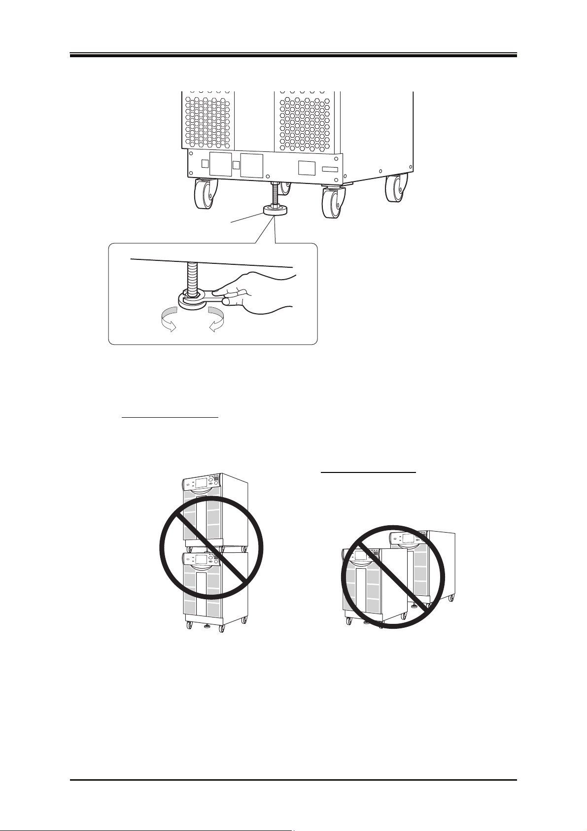
Do not install this product on a sloped surface. The Adjuster Foot is only for temporary fixing,
and cannot support the unit's own weight. You also must not lean on this product or use it as a
support. How to use the Adjuster Foot is shown in Figure 2–1.
DP Series
9
Page 28
2. Preparation before Use
p
Adjuster Foot
Up
The Adjuster Foot can be moved
up by turning it to left
(counterclockwise) as viewed from
above, and moved down by turning
it to right (clockwise). Move the
Adjuster Foot down by using a
spanner (19 mm diameter).
Down
Figure 2-1 How to Use the Adjuster Foot
About arrangement
Stacking arrangement
• The center of gravity becomes high, which
poses a risk of falling down.
• The product does not have a structure for
supporting a heavy load.
Tandem arrangement
• The product placed behind
another will be overheated by
exhaust heat, which reduces
roduct's lifetime.
the
Do not place the product on its side or back.
Do not stack the product on top of the other, or place it in front or back of the other
(arrangement which makes the cabinet placed behind inhale the exhaust heat of the other).
When you use multiple cabinets to form a polyphase system, there is no limitation regarding
the order of the phases to be arranged. Arrange them in your convenient order within the range
of the length of the System Cable.
10
PROGRAMMABLE AC POWER SOURCE
Page 29
2.3 Cautions during Moving and Transportation
Other installation location conditions
Use the product indoors, at altitude up to 2000 m.
Use the product where the temperature is 0 to +50 degrees Celsius, and the humidity is 5 to
3
85%RH (the absolute humidity should be 1 to 25 g/m
, without condensation). However, on
some specifications, the temperature range limit is more strict.
Do not install the product in the following places:
Place exposed to inflammable gas
→This may pose a risk of explosion. Never install and use the product in such a place.
Outdoors, place exposed to direct sunlight, or place near fire or heat source
→This may reduce the performance, or cause failure.
Place exposed to corrosive gas or water, or humid place
→This may cause corrode or failure.
Place near electromagnetic field source, high-voltage equipment, or power line
→This may cause malfunction.
Place of frequent vibration
→This may cause malfunction or failure.
Dusty place
→This may cause failure. Especially do not install the product in a place with conductive
dust.
2.3 Cautions during Moving and Transportation
Follow the instructions below when moving or transporting this product.
Remove all wirings connected to this product.
Before removing the wiring, be sure to turn off this product to cut the power from the
Check before movement and transportation
Check the weight before moving the product ( Table 2-3).
If
Moving with casters
The casters attached to this product is intended for use to move the product on a horizontal surface.
To move the product on a sloped or uneven surface, a licensed personnel should move it by
operating a lifting machine or crane instead of the casters.
As this product is heavy, whenever it is moved, at least two people are required to move it.
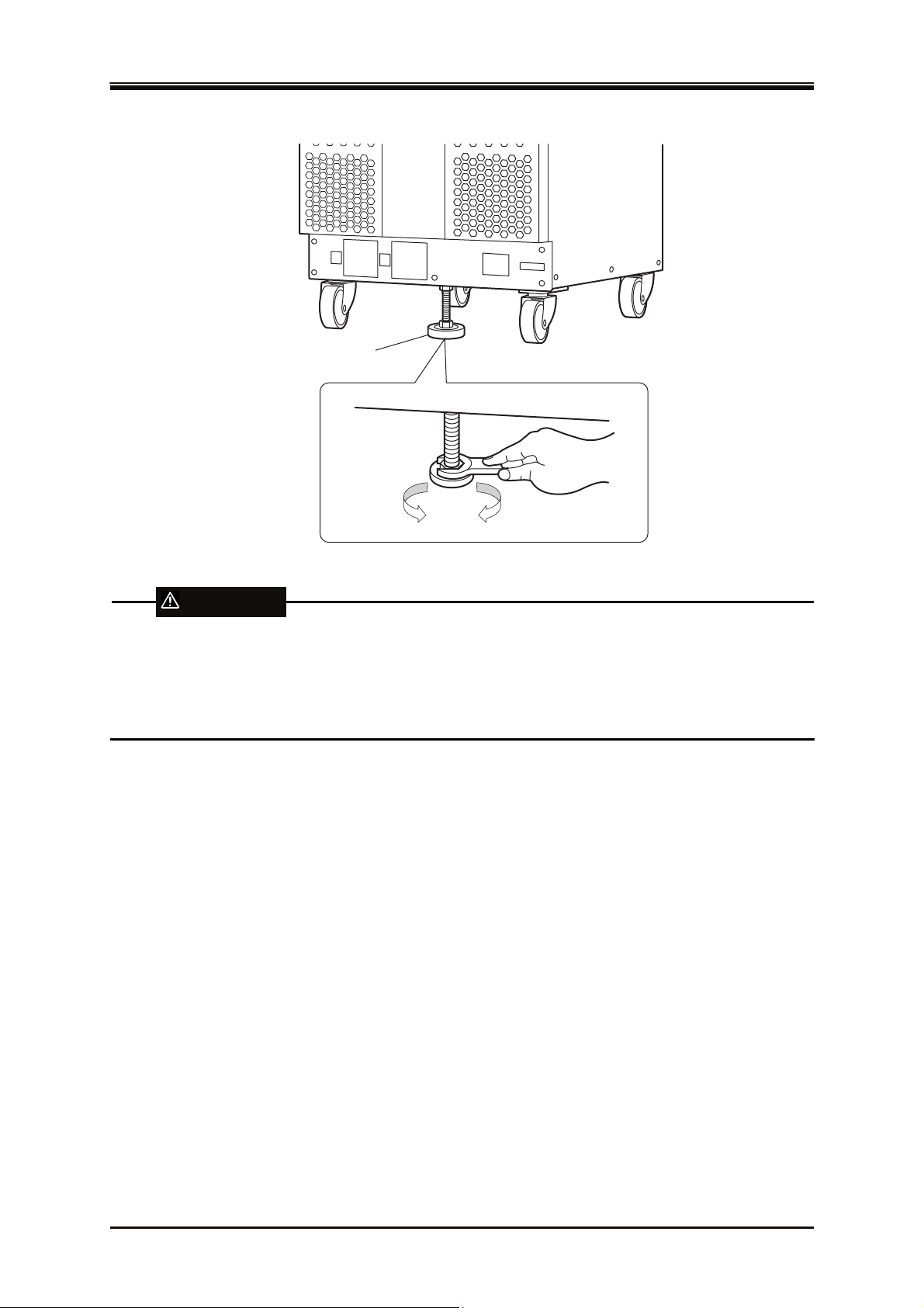
Move the Adjuster Foot up enough from the floor by using a spanner (19 mm diameter). You
WARNING
distribution board. Otherwise, an electric shock might occur.
you transport this product, consult with the seller (NF Corporation or our agent) from whom
you purchased the product.
can move the Adjuster Foot up by turning it counterclockwise as viewed from above.
DP Series
11
Page 30
2. Preparation before Use
Adjuster Foot
Up
Down
WARNING
Do not use the casters to move this product on a sloped surface. This product may move
automatically due to its own weight, and cause physical injury.
Do not use the casters to move this product on a uneven or irregular surface. This product may
fall down, and cause physical injury.
12
PROGRAMMABLE AC POWER SOURCE
Page 31
2.4 Grounding and Power Connections
2.4 Grounding and Power Connections
Ensure to ground.
This product uses a line filter. If the product is not grounded, an electric shock might occur.
WARNING
Ensure to connect the protective conductor terminal of the power input terminal of this product
to an earth ground so that ground resistance is 100Ω or less. If the product is not certainly
grounded, an electric shock might occur.
For grounding, use the supplied power cable or an equivalent cable whose diameter is same or
greater (see Table 2-5).
Before connecting the product to power source, check the followings.
WARNING
The power supply for this product must be taken from the distribution board.
Before connecting this product to the distribution board, be sure to cut the power to the
distribution board. Otherwise, an electric shock might occur.
Route the wire so that the distance between this product and the distribution board switch
(breaker) is 3 m or less. If the distance with the distribution board exceeds 3 m, install another
switch within 3 m from this product to connect. Use a switch that can cut the power from both L
and N (excluding protective grounding).
Condensation may form inside the product when the ambient temperature or humidity changes
Check the power source
For safety, use the product in the ranges of input voltage and frequency described below. Connect
the product to a distribution board which provides the power sufficiently higher than the maximum
input power of each model (see Table 2-5). For the models of which rated output is 6 kVA or more,
i
wattage limiter function of this product. For details, see 4.1.5.
V
Frequency range: 50 Hz/60 Hz
CAUTION
suddenly, for example, after transportation in winter. In such case, leave the product in room
temperature enough time to evaporate the condensation, and then connect the product to the
power source.
f the power input voltage is 170 V or less, the maximum output active power is restricted by the
oltage range: Single-phase 100 to 230 V
DP Series
13
Page 32
2. Preparation before Use
About power input terminal
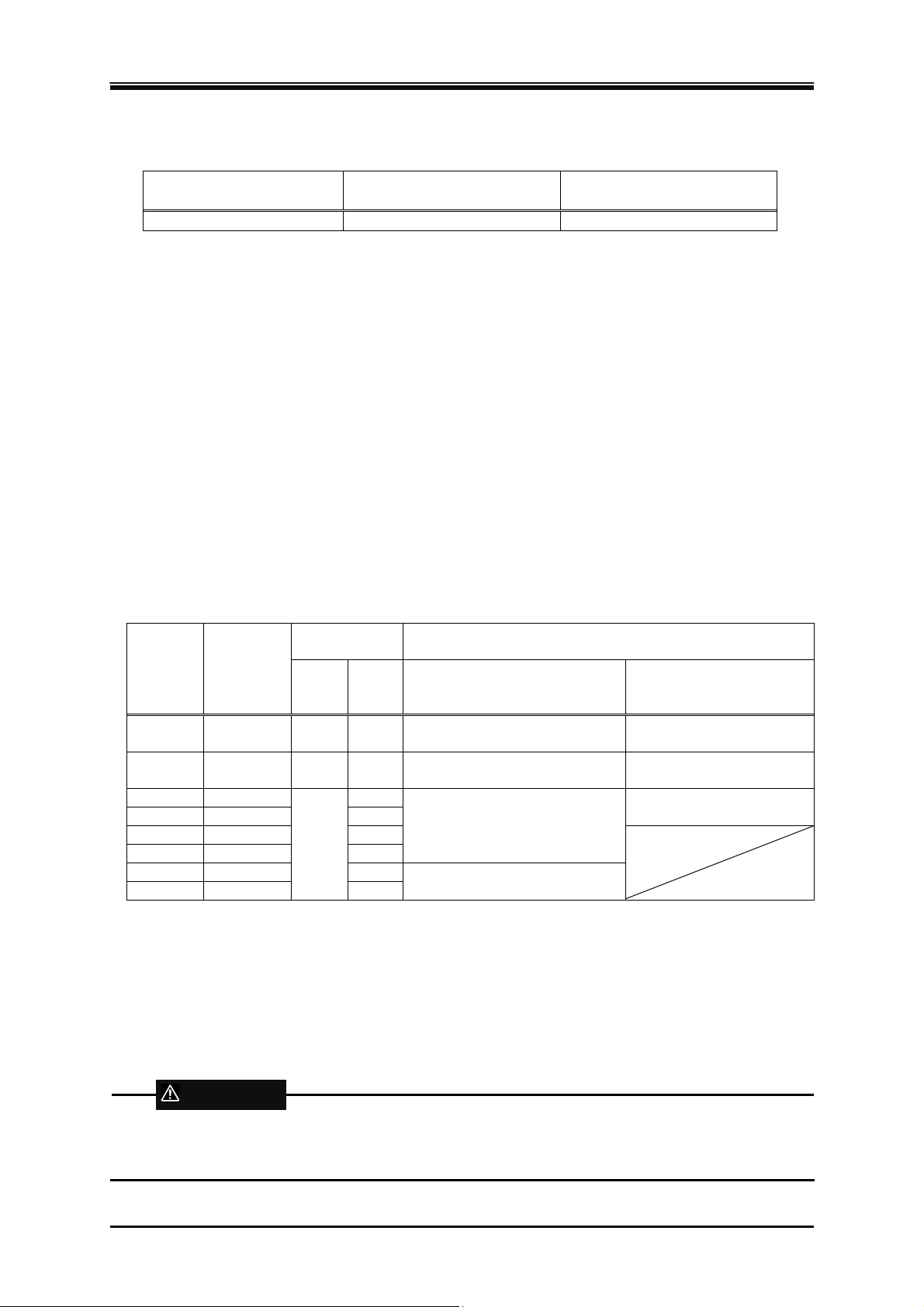
Table 2-4 Power Input Terminal
DP015, DP030,
DP045, DP060
DP075, DP090,
DP105, DP120
Screw M6 M8
About power input cable
The power input cable supplied with this product varies in diameter depending on the rated output as
shown in Table 2-5. A crimp-type terminal is attached to each cable on the end which is to be
connect
ed to the input terminal of this product.
On the supplied power input cable, the end which is to be connected to the distribution board
has no terminal attached. Use a crimp-type terminal appropriate for the terminal screw
diameter of the distribution board to connect the cable firmly.
The supplied power input cable is dedicated only to this product. Do not use it with any other
product.
When you use a power input cable other than the one supplied with the product, select a cable
which has an appropriate diameter in consideration of the safety standards and consumption
current. Use a protective grounding conductor of which diameter is the same or greater than
the power input cable.
Table 2-5 Maximum Input Power/Current and Power Input Cable
Maximum
Rated
output
Maximum
Input
Power
Input Current
Power
Input
90 V
Power
Input
170 V
For both 100 V and 200 V series
(Power Input 90 V or More)
1.5 kVA 2.25 kVA 25 A 13 A AWG10
(5.5 mm
3 kVA 4.50 kVA 50 A 26 A AWG6
(14 mm
4.5 kVA 6.75 kVA 40 A
6 kVA 9.00 kVA 53 A
7.5 kVA 11.25 kVA 66 A
9 kVA 13.50 kVA 79 A
75 A
(22 mm
10.5 kVA 15.75 kVA 93 A
12 kVA 18.00 kVA
Note: The model of which rated output is 6 kVA or less contains either a power cable for both 100 V and 200 V
series input or a power cable only for 200 V series input, depending on the destination of shipment. The
dedicated cable only for 200 V series input must be used with power supply voltage of 170 to 230 V.
106 A
(38 mm
Supplied power input cable
2
approx.)
2
approx.)
AWG4
2
approx.)
AWG2
2
approx.)
Only for 200 V Series
(Power Input 170 V or More)
AWG14
(2.1 mm2 approx.)
AWG10
(5.5 mm2 approx.)
AWG6
2
(14 mm
approx.)
Power source connection procedure
Check the current capacity of the single-phase distribution board before wiring. The wiring must be
performed by a professional engineer.
WARNING
Before connecting this product to the power source, be sure to cut the power to the distribution
board. Otherwise, an electric shock might occur.
14
PROGRAMMABLE AC POWER SOURCE
Page 33
2.4 Grounding and Power Connections
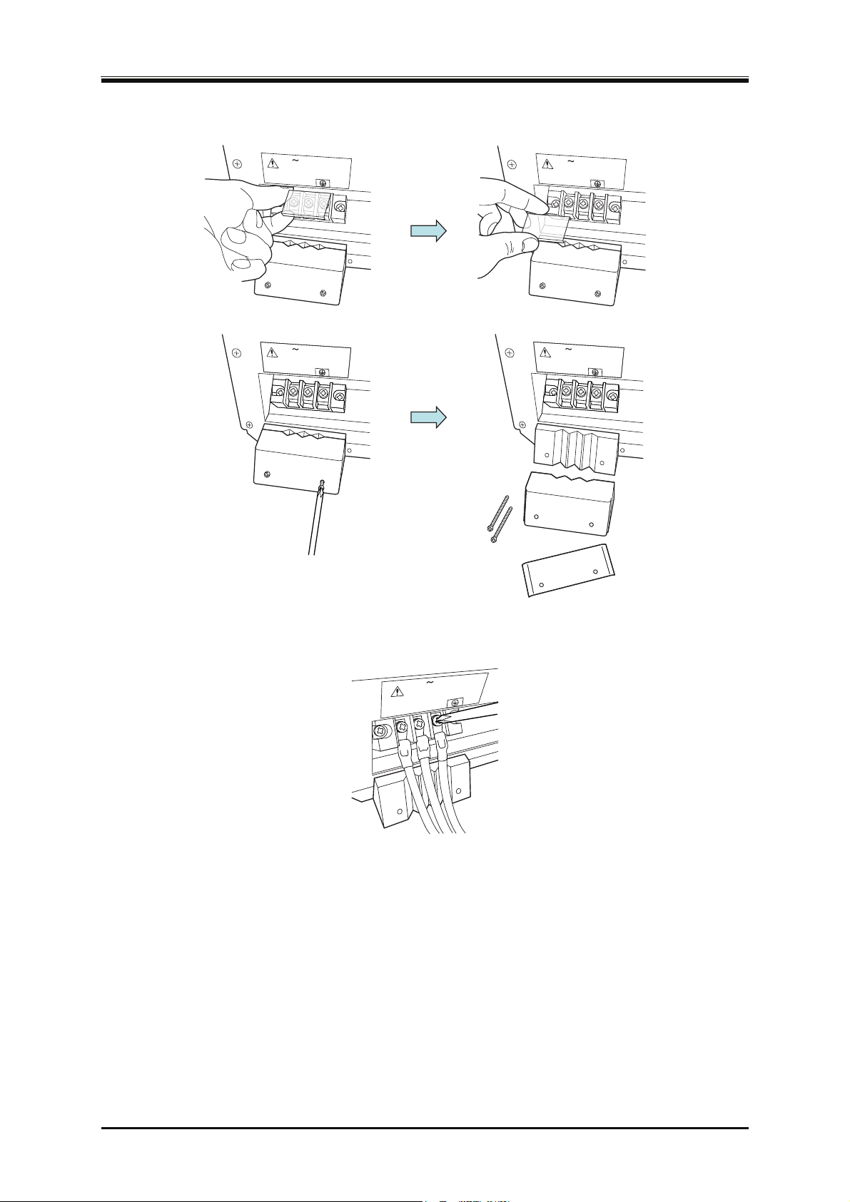
Remove the resin-molded power input terminal cover and the power input cable holder.
1.
LINE
L
N
LINE
L
N
LINE
L
N
LINE
L
N
Connect the power input cable to the power input terminal of this product. Be sure to tighten the
2.
screws firmly.
LINE
N
L
DP Series
15
Page 34
2. Preparation before Use
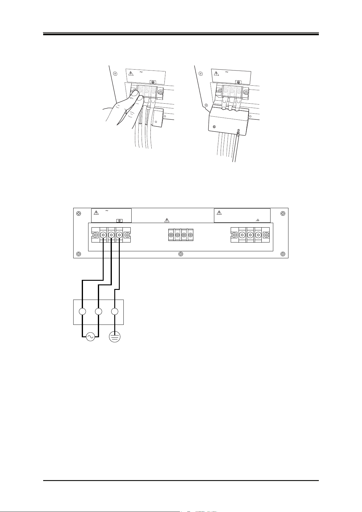
Attach the resin-molded power input terminal cover and the power input cable holder.
3.
LINE
L
N
LINE
L
N
Ensure that the power switch of this product is turned off, and then connect the power input
4.
cable to the single-phase distribution board.
LINE OUTPUT
LN Hi Lo
SENSEHiINPUT
Lo
16
Distribution board
(Protective grounding)
PROGRAMMABLE AC POWER SOURCE
Page 35
2.5 Output and System Cable Connection
2.5 Output and System Cable Connection
Before connecting, check the followings.
Before touching the output terminal, be sure to turn off the power switch of this product, and cut
The output terminals that can be grounded are the Lo or N terminals. Do not ground the Hi, L1,
About output terminal
WARNING
the power to the distribution board. Otherwise, an electric shock might occur.
CAUTION
L2, and L3 terminals.
Table 2-6 Output Terminals
DP015, DP030,
DP045, DP060
DP090D, DP090T,
DP120D,
DP090M (polyphase output)
DP075S, DP090S,
DP105S, DP120S,
DP090M (single-phase output)
Screw M6 M8
2.5.1 Single-phase Model
Connection procedure
Remove the resin-molded output terminal cover and the output cable holder of the output
1.
terminal.
OUTPUT
OUTPUT
Hi
Lo
Hi
Lo
OUTPUT
OUTPUT
Hi
Lo
Hi
Lo
DP Series
17
Page 36
2. Preparation before Use
Connect the output terminal to the load with a cable. Be sure to tighten the screws firmly. If you
2.
want to ground the output terminal at one point only, ground the Lo terminal. The Hi terminal
should not be grounded. If the load has a ground terminal, connect it to the ground terminal of
the output terminal of this product.
CAUTION
The output terminal that can be grounded is the Lo terminals. Do not ground the Hi terminal.
OUTPUT
Lo
Hi
Attach the resin-molded terminal cover and the output cable holder.
3.
OUTPUT
Hi
Lo
OUTPUT
Hi
Lo
About outlet
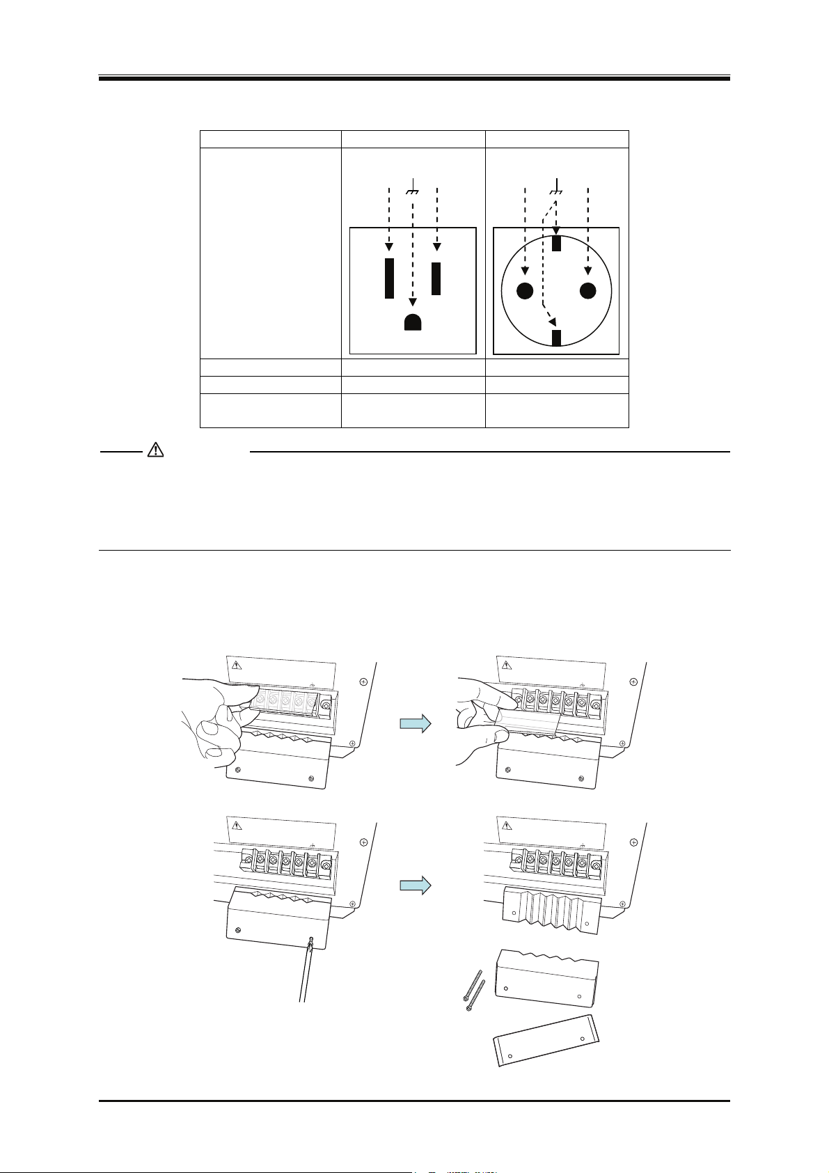
If you purchase a single-phase model, you need to specify the outlet type to either NEMA 5-15
(Japan/North America type) or CEE 7 (Europe type). The model name of this product is
distinguished by this outlet type (Figure 1–1). The output terminals, the maximum voltage, the
m
aximum current, and available output range are listed for each type in Table 2-7.
Each outlet can pro
vide up to 15 A of current. If a current exceeding 15 A flows, the circuit breaker
may operate to cut the output. When the circuit breaker operates, the button is pushed out forward.
Pushing in this button resets the breaker, and power can be provided from the outlet.
The outlet is dedicated to AC output. It can be used in the AC or ACDC mode. In the settings below,
the outlet is separated from the output by the internal relay of this product. However, only the Hi
terminal is separated.
When in DC mode (DC-INT, DC-VCA)
When the outlet is the Japan/North America type (NEMA 5-15), and in the 200 V range
18
PROGRAMMABLE AC POWER SOURCE
Page 37
2.5 Output and System Cable Connection
Table 2-7 Outlet List
Type NEMA 5-15 CEE 7
Lo
Hi
Lo
Hi
Form
and Terminals
Maximum Voltage 125 Vrms 250 Vrms
Maximum Current 15 Arms 15 Arms
Available
Output Range
100 V range
100 V range
200 V range
CAUTION
Use the outlet only for AC output without DC offset. Do not take DC output or AC output with
DC offset from the outlet.
Use the outlet for 15 A or less output.
2.5.2 Polyphase Model
Connection procedure
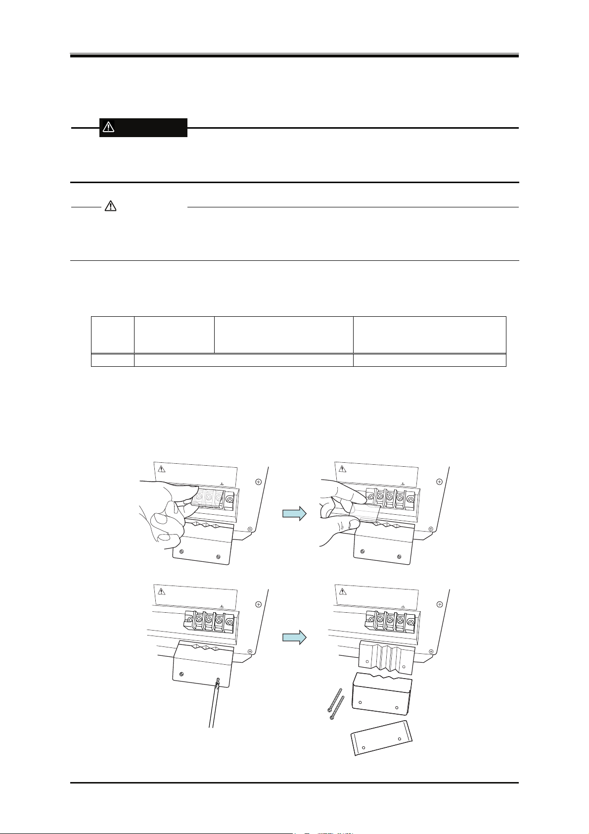
Remove the resin-molded terminal cover and the output cable holder of the output terminal.
1.
OUTPUT
L1
OUTPUT
L1
OUTPUT
L2
L3
N
L2
L3
N
L1
OUTPUT
L1
L2
L3
N
L2
L3
N
DP Series
19
Page 38
2. Preparation before Use
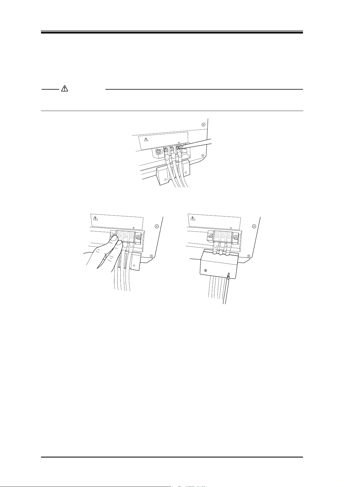
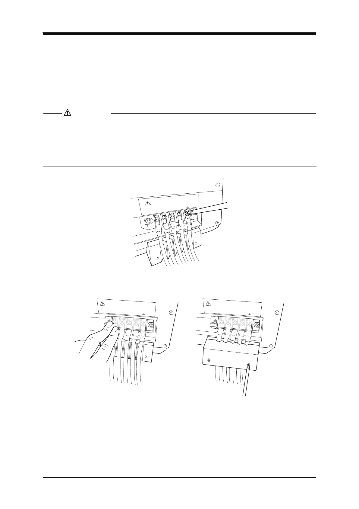
Connect the output terminal to the load with a cable. Connect voltage lines to the L1, L2, and
2.
L3 output terminals of this product. Connect a neutral line to the N terminal of output terminal
of this product, if necessary. Be sure to tighten the screws firmly. In both single-phase
three-wire model and three-phase model, the N terminal can be grounded. If the load has a
ground terminal, connect it to the ground terminal of the output terminal of this product.
CAUTION
The output terminal that can be grounded is the N terminals. Do not ground any of the L1, L2,
and L3 terminals.
Do not flow any current exceeding the maximum current per phase (see 10.5 and 10.6) to
the N
terminal of the output terminal.
OUTPUT
N
L3
L2
L1
Attach the resin-molded terminal cover and the output cable holder.
3.
OUTPUT
L1
L2
L3
N
OUTPUT
L1
L2
L3
N
20
PROGRAMMABLE AC POWER SOURCE
Page 39
2.5 Output and System Cable Connection
2.5.3 Multi-phase Model
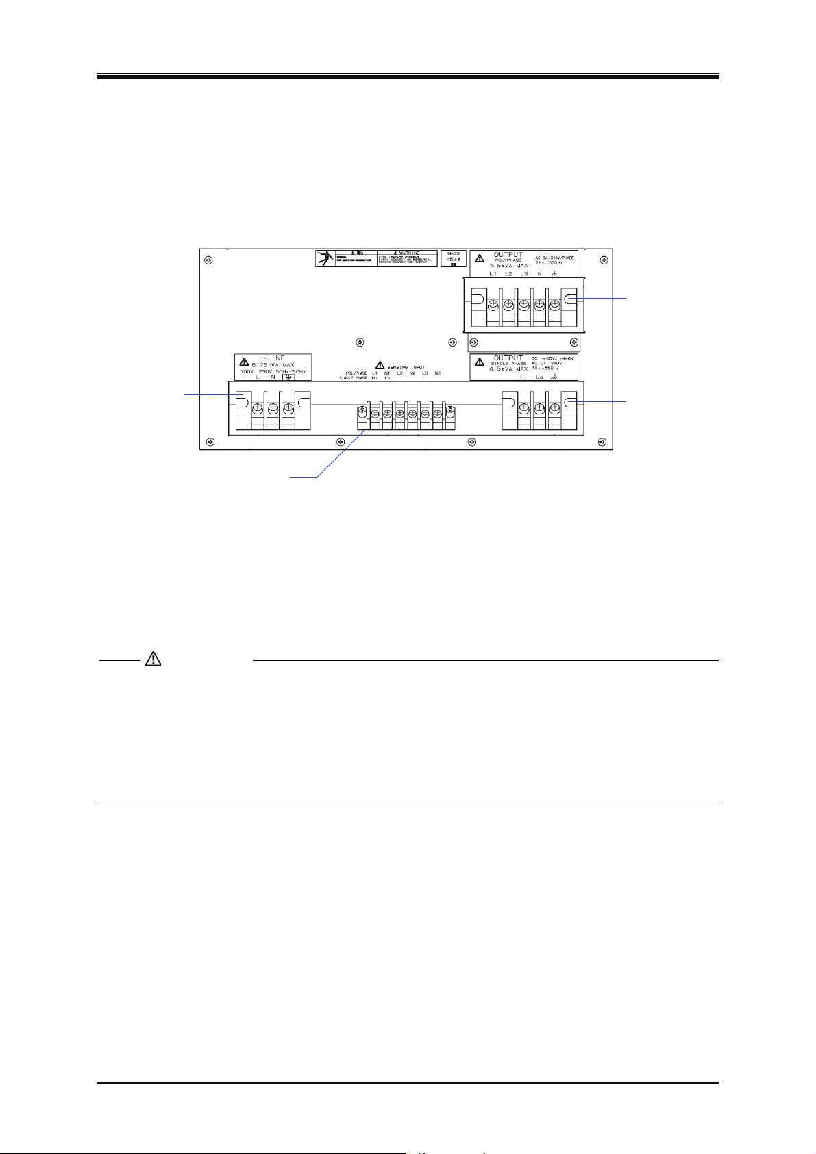
The output terminal of DP045M/DP090M is divided into two terminals, the polyphase output
terminal and the single-phase output terminal, as shown in Figure 2–2. The single-phase two-wire
(1P
2W) output uses the single-phase output terminal, and the single-phase three-wire (1P3W) output
and the three-phase four-wire (3P4W) output use the polyphase output terminal.
多相出力端子
Polyphase output terminal
(Used for the single-phase
単相3線出力,
three-wire output and the
三相4線出力
で使用します。
three-phase four-wire
output.)
電源入力端子
Power input
terminal
Single-phase output
単相出力端子
terminal
単相2線出力
(Used for single-phase
で使用します。
two-wire output.)
Sensing input terminal
センシング入力端子
Figure 2-2 Terminal Panel Arrangement of Multi-phase Model (Rear)
Connection procedure
The connection procedure of the single-phase output terminal follows the description in 2.5.1,
that of the polyphase output terminal follows 2.5.2.
CAUTION
I
n the single-phase two-wire (1P2W) output, do not connect anything to the polyphase output
terminal.
In the single-phase three-wire (1P3W) output and the three-phase four-wire (3P4W) output, do
not connect anything to the single-phase output terminal.
In the single-phase three-wire (1P3W) output, do not connect anything to the L3 terminal.
and
DP Series
21
Page 40
2. Preparation before Use
2.5.4 Polyphase System
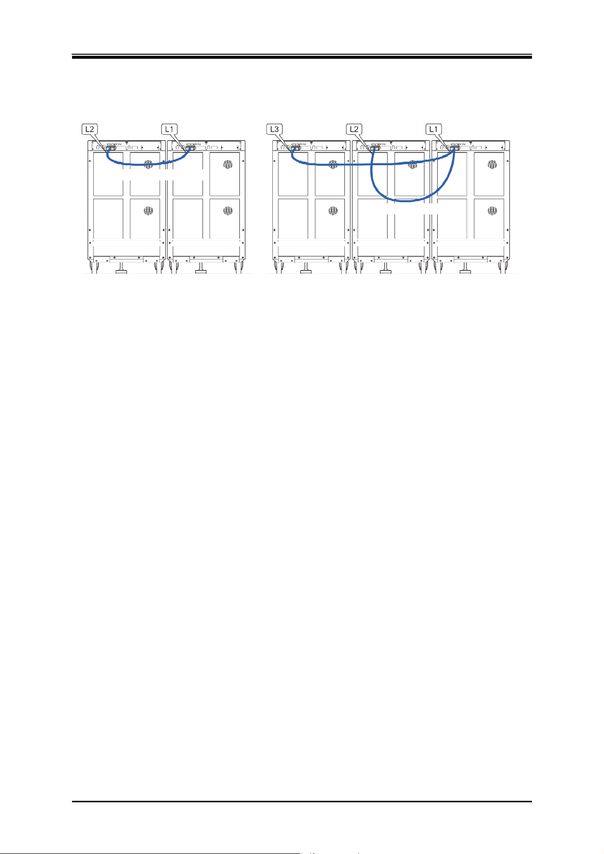
System Cable (1P3W)
System Cable (3P4W)
Single-phase three-wire system Three-phase four-wire system
Optional System Cable should be connected to the SYSTEM I/O connector of this product. The
cabinet which the L1 connector of the System Cable is connected to becomes L1 phase, and the
output terminals Hi and Lo correspond to the L1 and N terminals, respectively. This is same for L2
and L3 phases. This product recognizes the polyphase system by checking the state of the system
cable connection at power-on, so connect the System Cable before turning on the power.
-------- Notes----------------------------------------------------------------------------------------------------------------
The polyphase system can be configured only when the same single-phase models are
connected with System Cables.
The models with different model names cannot be connected.
Connection with polyphase model or Multi-phase model is not allowed.
You cannot use a Multi-phase model to configure a polyphase system, even when it is used as
a single-phase output.
You cannot connect single-phase models in parallel to boost up a single-phase output.
Turn on all power supplies within 20 seconds.
The L2 and L3 cabinets in a polyphase system are restricted in their operation as follows:
Cannot use the communication interface (USB, RS232, GPIB).
Cannot use the external control.
Cannot use a USB memory.
Cannot connect and use the remote controller.
Starts according to the contents of the Basic Setting Memory No.1 of the L1 cabinet.
Does not accept the control panel key operations except for special cases.
Can only display the output measured value of their own cabinet in the measurement display.
The display format of the measured value (
3.4.10) follows that of the LI cabinet.
---------------------------------------------------------------------------------------------------------------------------------
22
PROGRAMMABLE AC POWER SOURCE
Page 41
Connection procedure
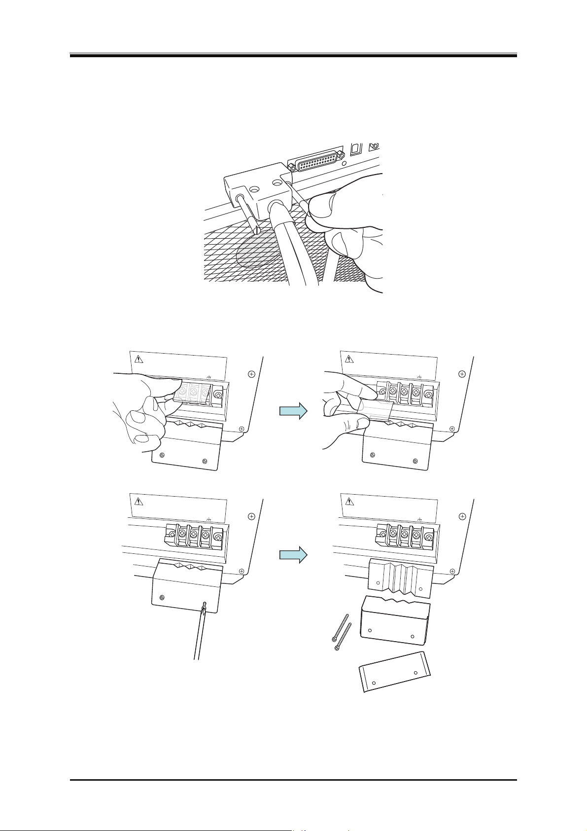
Connect the connector L1 of the System Cable to the SYSTEM I/O connector of the cabinet
1.
which is to be L1 phase. Also connect the L2 and L3 connectors in the same way.
Remove the resin-molded output terminal cover and the output cable holder of each cabinet.
2.
OUTPUT
2.5 Output and System Cable Connection
CONTROL I/O
SYSTEM I/O
OUTPUT
OUTPUT
Hi
Lo
OUTPUT
Hi
Lo
Hi
Lo
Hi
Lo
DP Series
23
Page 42
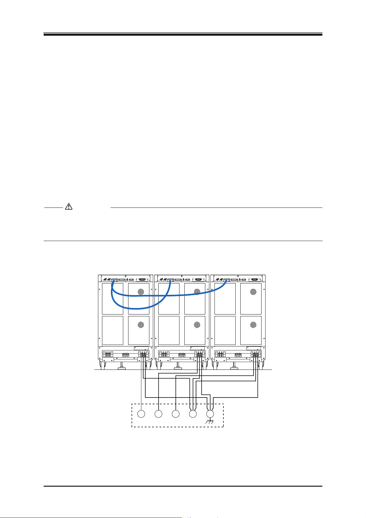
2. Preparation before Use
Connect the output terminal to the load with a cable. Connect a voltage line to the Hi output
3.
terminal of each cabinet. The neutral line can be connected to the Lo terminal with two methods
described below. The neutral line can be grounded. If the load has a ground terminal, connect it
to the ground terminal of each output terminal. Be sure to tighten the screws firmly.
(a) When connecting the load with the neutral line (single-phase three-wire or three-phase
four-wire connection)
Connect the neutral point of load with the Lo terminal of each cabinet using cables with
same length and diameter as the voltage line. Alternatively, connect between the Lo
terminals of each cabinet by a cable which is as short as possible and has a diameter equal
to or more than that of the voltage line, and then connect one of the Lo terminals with the
neutral point of load by a cable with same length and diameter as the voltage line.
(b) When not connecting the load with the neutral line (three-phase three-wire connection),
Connect between the Lo terminals of each cabinet by a cable which is as short and thick as
possible (with a diameter equal to or more than that of the voltage line).
CAUTION
The terminal which can be grounded is the Lo terminal of each cabinet. Do not ground the Hi
terminal (L1, L2, and L3 voltage lines).
OUTPUT
Hi Lo
OUTPUT
Hi Lo
L3L2L1
OUTPUT
Hi Lo
24
L1 L2 L3 N
(Cabinet ground terminal)
(a)Three-phase four-wire connection
a 4
PROGRAMMABLE AC POWER SOURCE
Load
Page 43
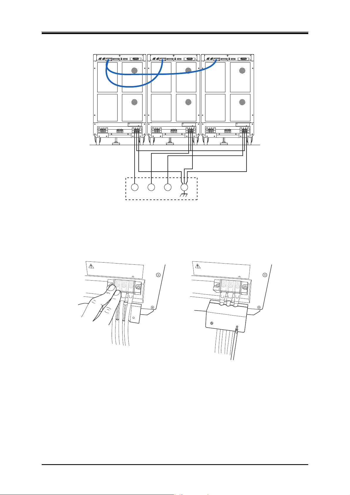
2.5 Output and System Cable Connection
OUTPUT
Hi Lo
OUTPUT
Hi Lo
L3L2L1
OUTPUT
Hi Lo
Load
L1 L2 L3
(Cabinet ground terminal)
(b)Three-phase three-wire connection
b 3
Attach the resin-molded output terminal cover and the output cable holder to each cabinet.
4.
OUTPUT
Hi
Lo
OUTPUT
Hi
Lo
DP Series
25
Page 44
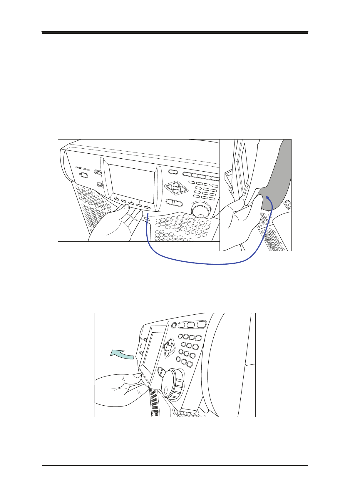
2. Preparation before Use
2.6 How to Tilt Control Panel
You can tilt up the control panel to operate it. There is a lever in the back under the control panel,
which is locked with the hook of the chassis, being pulled by a spring. The hook consists of two
steps, which can be used to tilt the control panel and fix it in two way.
Operation procedure
Pull the lever in the back under the control panel. The handle moves toward you and the lock of
1.
the control panel is released.
Pull the lever in the back
While holding the lever in pulled position, tilt the control panel by desired degree.
2.
Release the lever slowly. The control panel will be locked.
3.
26
PROGRAMMABLE AC POWER SOURCE
Page 45
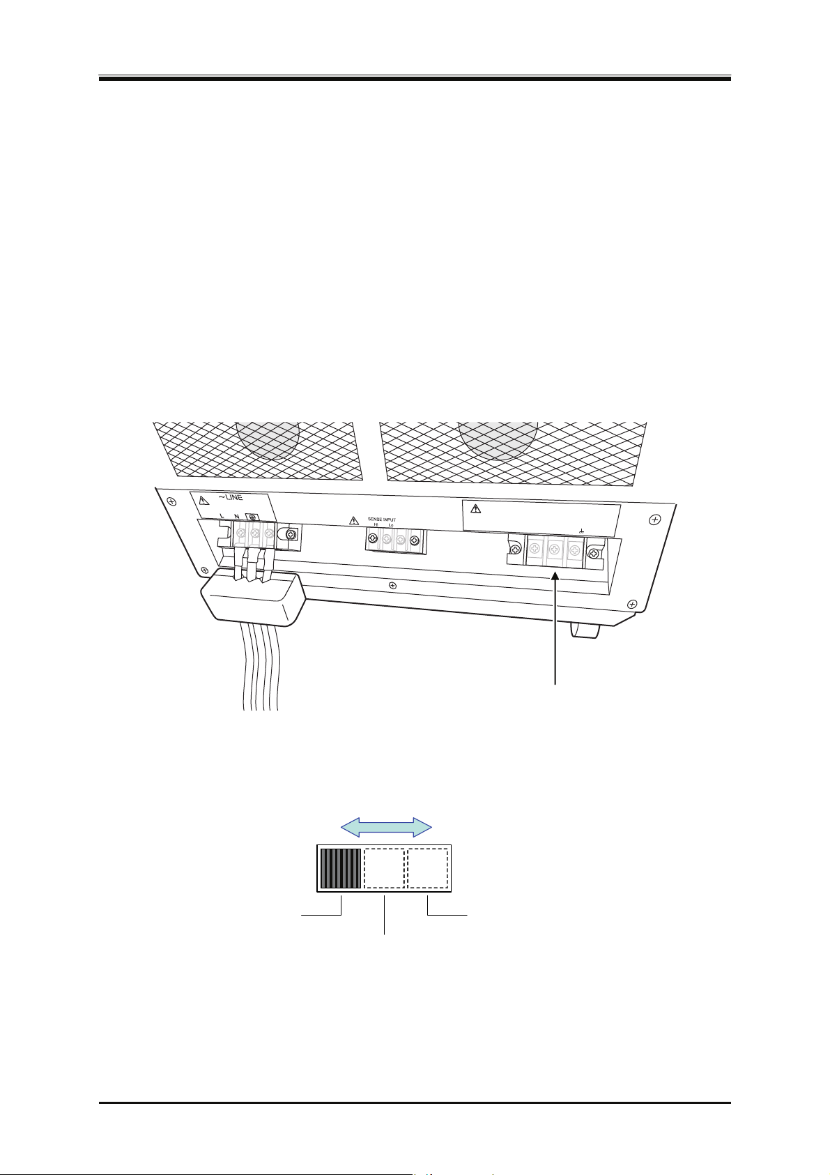
2.7 Simple Operation Check
2.7 Simple Operation Check
This section describes how to perform a simple operation check when you purchased a new product,
or after storing the product for a long period. This check should be performed without load. For a
polyphase system, remove the System Cable, and check the single-phase output for each cabinet. If
you are not satisfied with the results verified at the operation check, please request the repair to us or
our agent.
Operation procedure
Connect the power supply referring to "
1.
2.4 Grounding and Power Connections
Attach the resin-molded output terminal cover and the output cable holder without connecting
2.
anything to the output terminals or any other terminal/connector.
."
OUTPUT
Hi
Lo
Nothing is connected to
the output terminal.
«Only for Multi-phase model» For the Multi-phase model, set the phase mode setting switch
3.
according to the output phase mode to be checked.
スイッチをスライド
Set the switch by sliding it.
させて設定す
DP Series
1φ2W
1φ3W
3φ4W
27
Page 46
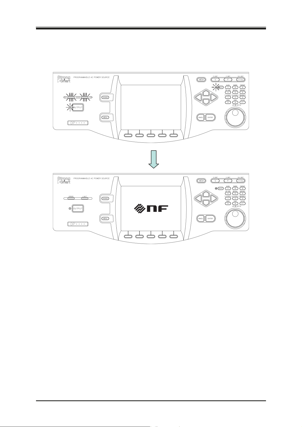
2. Preparation before Use
Turn on the switch of the distribution board, and then turn on the power switch of this product.
4.
Check that all LEDs on the control panel illuminate for several seconds, and then turn off, and
that our logo mark appears on the LCD screen (see
).
3.2.4
Except when you purchased a new product, refer to "
5.
etting
S
(Reset)" to initialize the product to factory defaults. The product will be reset, and
4.28 Restoring to the Factory Default
display the Continuous screen automatically.
When you purchased a new product, the product will start and then display the Continuous
6.
screen automatically.
28
PROGRAMMABLE AC POWER SOURCE
Page 47
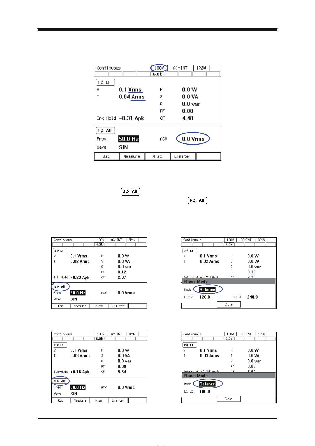
2.7 Simple Operation Check
Check that the measured values of 100 V range, AC-INT, V, and I are displayed in rms, and that
7.
the AC voltage (ACV) is set to 0 V.
«Only for the polyphase model, the polyphase output of the Multi-phase model, or the
8.
polyphase system» As shown in the figure below, for the three-phase model or three-phase
system, check that the icon is displayed, and for the single-phase three-wire model or
the single-phase three-wire system, check that the icon
is displayed. Press the [Osc]
soft-key and select [6: Phs Mode] to display the [Phase Mode] window, and check that the
mode is set to [Balance] (balanced mode).
Three-phase model, three-phase output of Multi-phase model, or three-phase system
三相モデル・マルチ相モデル
Single-phase three-wire model, single-phase three-wire output of Multi-phase model, or single-phase three-wire
単相3線モデル・マルチ相モデルの単相3線出力・単相3線システム
system
の三相出力・三相システム
DP Series
29
Page 48
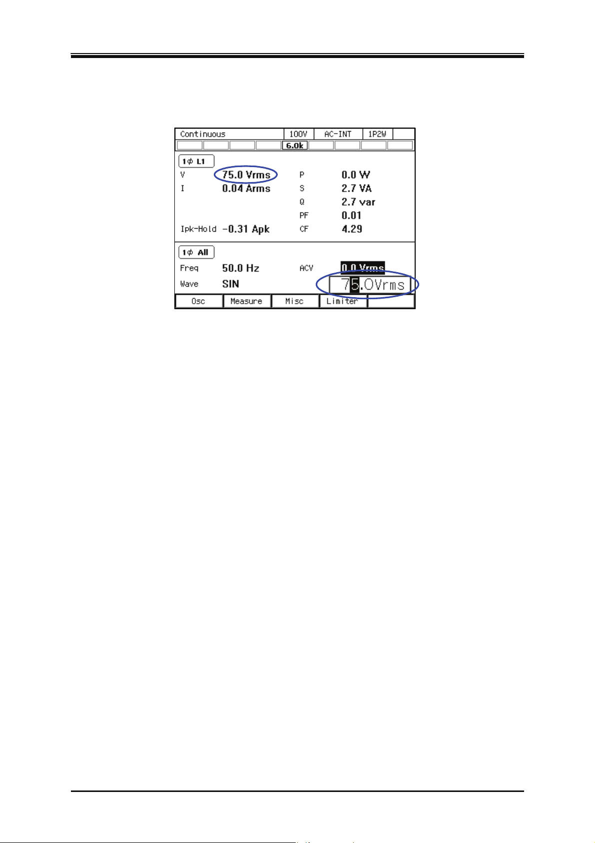
2. Preparation before Use
Press the OUTPUT key to turn the output on. Press the V key to open the numerical entry box
9.
for AC voltage (ACV). Raise the AC voltage setting value gradually by using the jog, shuttle,
arrow keys, and numeric keypad.
2.8 Calibration
When the product needs calibration, contact us or our agent.
30
PROGRAMMABLE AC POWER SOURCE
Page 49

3. Basic Operation
3.1 Component Name ····················································· 32
3.2 Power On/Off····························································· 37
3.3 Basic Key Operations················································ 41
3.4 Using the Continuous F
unction ································· 47
DP Series
31
Page 50
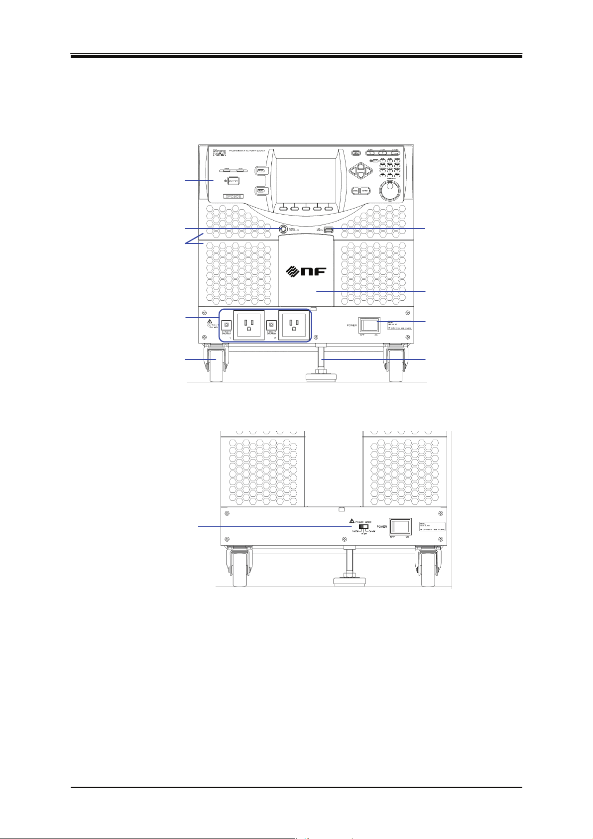
3. Basic Operation
3.1 Component Name
3.1.1 Front
1. 操作パネル
1. Control panel
2. リモートコントローラコネクタ
2. Remote controller connector
4. フロントグリル
4. Front grill
6. Outlet
6. 出力アウトレット
8. Caster
8. キャスタ
(Multi-phase model)
3. USB memory connector
3. USBメモリコネクタ
5. Front grill holder
5. フロントグリル固定金具
7. Power switch
7. 電源スイッチ
9. アジャスタフット
9. Adjuster Foot
10. 相モード設定スイッチ
10. Phase mode setting switch
32
Figure 3-1 Component Name (Front)
PROGRAMMABLE AC POWER SOURCE
Page 51
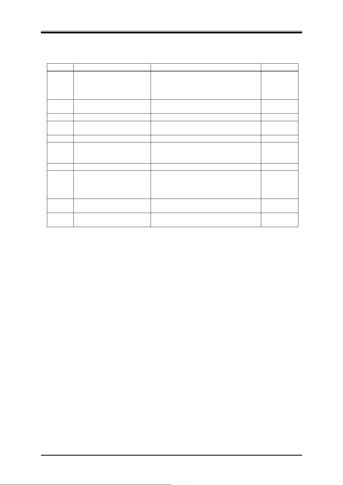
3.1 Component Name
Table 3-1 Component Name (Front)
Number Name Description Refer to
1 Control panel Configures the settings and turns the
3.1.3
output on or off. Information such as
setting values and measured values is
displayed on the LCD screen.
2 Remote controller
connector
3 USB memory connector USB memory can be connected.
4 Front grill The fresh air inlet. An air filter is
Optional remote controller can be
connected.
7.4
4.9
9.2
attached.
5 Front grill holder Clasps for fixing the front grill.
6 Outlet
(Only for the single-phase
Can provide up to 15 A of AC output per
outlet.
9.2
2.5
model)
7 Power switch Turns the power on/off.
8 Caster Caster with the freely movable
3.2
2.3
front-wheels and fixed rear-wheels. Can
be used to move this product in the
horizontal location.
9 Adjuster Foot Can be used to fix this product
2.2
temporarily in the horizontal location.
10 Phase mode setting switch
Set the output phase mode.
3.2.2
(Multi-phase model only)
DP Series
33
Page 52
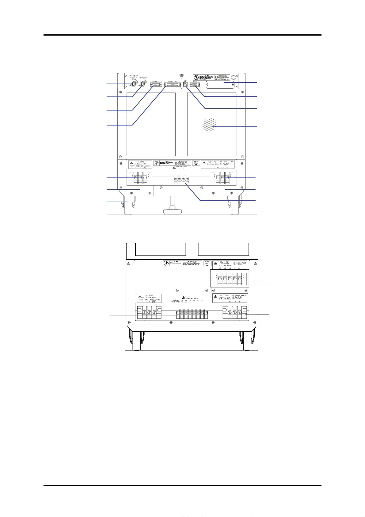
3. Basic Operation
3.1.2 Rear
1. External signal input
1. 外部信号入力コネクタ
2. Monitor output connector
3. SYSTEM I/Oコネクタ
3. SYSTEM I/O connector
4. CONTROL I/Oコネクタ
4. CONTROL I/O connector
connector
2. モニタ出力コネクタ
5. GPIB connector (optional)
5. GPIBコネクタ(オプション)
6. RS232コネクタ
6. RS232 connector
7. USBコネクタ
7. USB connector
8. 排気口
8. Air outlet
9. Power input terminal
10. 電源入力ケーブルホルダ
10. Power input cable holder
9. 電源入力端子
14. キャスタ
14. Caster
(Multi-phase model)
17. Sensing input terminal
17. センシング
入力端子
Figure 3-2 Component Name (Rear)
11. 出力端子
11. Output terminal
12. 出力ケーブルホルダ
12. Output cable holder
13. センシング入力端子
13. Sensing input terminal
15. 多相出力端子
15. Polyphase output
terminal
16. Single-phase
16. 単相出力端子
output terminal
34
PROGRAMMABLE AC POWER SOURCE
Page 53
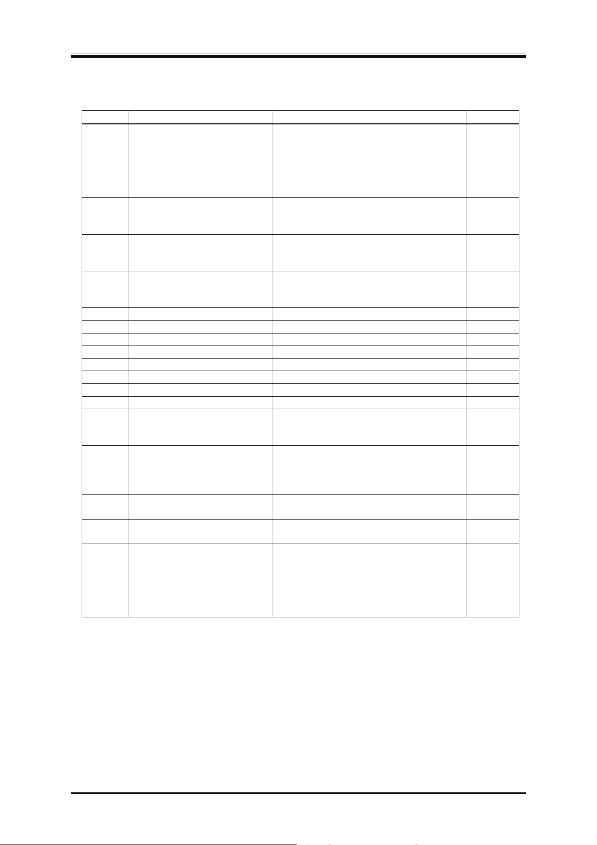
3.1 Component Name
Table 3-2 Component Name (Rear)
Number Name Description Refer to
1 External signal input
connector
Used when controlling the voltage value
setting by the external signal (VCA),
when synchronizing the output frequency
with the external signal (SYNC), and
when outputting the amplified external
signal (EXT
†
, ADD†).
2 Monitor output connector Can observe waveforms of the output
voltage and output current when
connected to a unit such as oscilloscopes.
3 SYSTEM I/O connector A System Cable† can be connected to
make multiple single-phase models into a
polyphase output system.
4 CONTROL I/O connector I/O connector used to control this product
externally by using the logic signal and
non voltage contact.
5 GPIB connector† GPIB communication interface.
6 RS232 connector RS232 communication interface.
7 USB connector USB communication interface.
8 Air outlet Air outlet for exhausting the heat.
9 Power input terminal Power input terminal.
10 Power input cable holder Used to fix the power input cable.
11 Output terminal Output terminal.
12 Output cable holder Used to fix the output cable.
13 Sensing input terminal
(Single-phase model,
Polyphase model)
Connect to the load end that is located in
the distance from the main unit to detect
its voltage.
14 Caster Caster with the freely movable
front-wheels and fixed rear-wheels. Can
be used to move this product in the
horizontal location.
15 Polyphase output terminal
(Multi-phase model)
16 Single-phase output terminal
(Multi-phase model)
17 Sensing input terminal
(Multi-phase model)
Output terminal for the single-phase
three-wire and three-phase four-wire.
Output terminal for the single-phase
two-wire.
Connect to the load end that is located in
the distance from the main unit to detect
its voltage. Common among the
single-phase two-wire, single-phase
three-wire, and three-phase four-wire
output.
Note: † indicates an option.
4.17,
4.19,
4.20
4.10
2.5.4
4.18
6.1.3
6.1.2
6.1.1
2.2
2.4
2.4
2.5
2.5
4.11
2.3
2.5.3
2.5.3
4.11
DP Series
35
Page 54
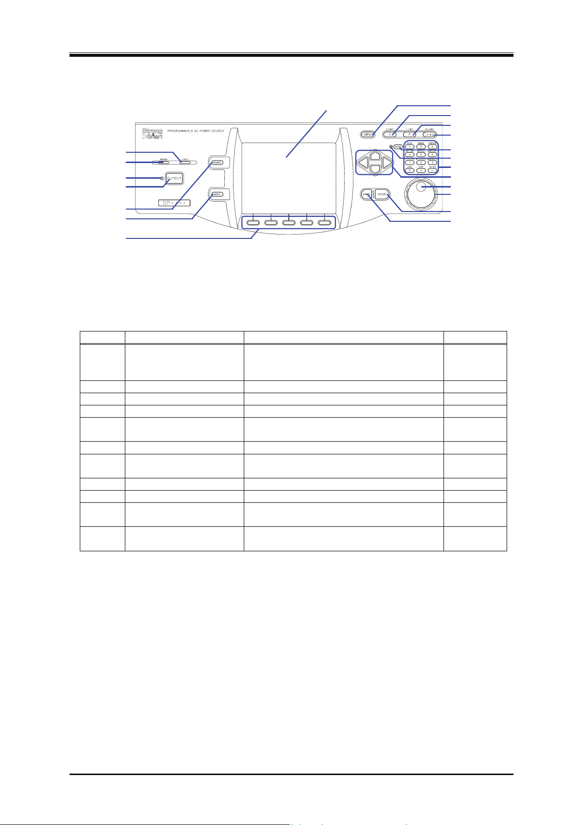
3. Basic Operation
3.1.3 Control Panel
1. LIMIT LED
2. ERROR LED
3. OUTPUT LED
4. OUTPUTキー
4. OUTPUT key
5. レンジキー
5. RANGE key
6. メニューキー
6. MENU key
7. Soft-key
7. ソフトキー
8. LCD画面
8. LCD screen
Figure 3-3 Component Name (Control Panel)
Table 3-3 Component Name (Control Panel)
9. メモリキー
9. MEMORY key
10. Vキー
10. V key
11. Fキー
11. F key
12. Iキー
12. I key
13. シフトキー
13. SHIFT key
14. SHIFT LED
14. シフトLED
15. Numeric keypad
15. テンキー
16. Arrow key
キー
16. 十字
17. Jog
17. ジョグ
18. シャトル
18. Shuttle
19. ENTERキー
19. ENTER key
20. CANCELキー
20. CANCEL key
Number Name Description Refer to
1 LIMIT LED Illuminates when the peak current limiter,
4.1
RMS current limiter, or active wattage
limiter activates.
2 ERROR LED Illuminates when an error is detected.
3 OUTPUT LED Illuminates in the output on state.
4 OUTPUT key Turns the output on or off.
5 RANGE key Switches between the 100 V and 200 V
8.1
3.4.8
3.4.8
3.4.2
ranges.
6 MENU key Displays the root menu.
7 Soft-key Assigned with the functions displayed at the
3.3.1
5.1
bottom of the LCD screen.
8 LCD screen Displays the measured values or menu.
9 MEMORY key Displays the Memory View.
10 V key Opens the numerical entry box for the
output voltage setting.
11 F key Opens the numerical entry box for the
5.1
4.8
3.4.4,
3.4.5
3.4.6
frequency setting.
36
PROGRAMMABLE AC POWER SOURCE
Page 55
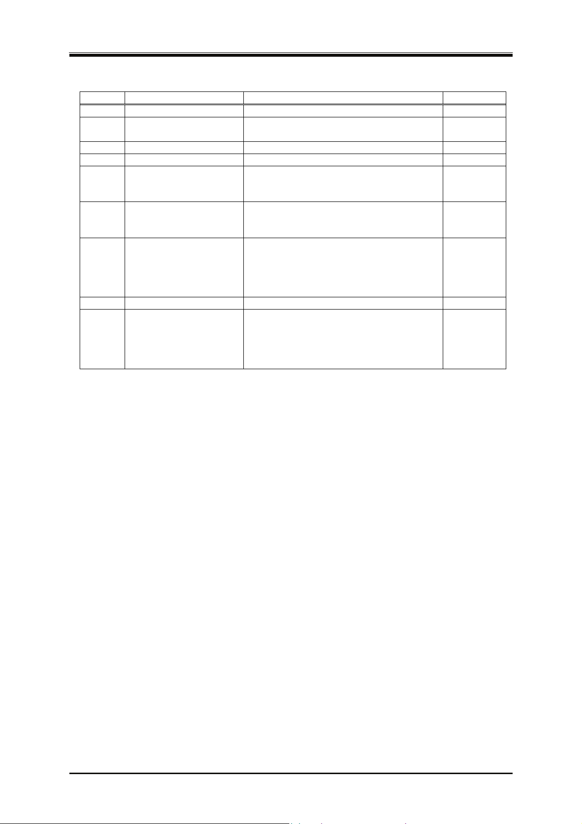
3.2 Power On/Off
Table 3-3 Component Name (Control Panel) (continued)
Number Name Description Refer to
12 I key Opens the RMS current limiter set window.
13 SHIFT key Turns on or off the shift state, which
enables Shortcut operations.
14 SHIFT LED Illuminates when the shift state is turned on.
15 Numeric keypad Used to enter a value directly.
16 Arrow key Used to move across the items or
incrementing/decrementing the value by
one step.
17 Jog Used to move across the items or
incrementing/decrementing the value by
one step.
18 Shuttle Used to move across the items in the
selection box or incrementing/decrementing
the value. The greater the turning angle is,
the faster you move or
increment/decrement.
19 ENTER key Confirms the selection.
20 CANCEL key Returns to the previous state without
confirming the selection. The numerical
entry box is closed when the value was
incremented or decremented using the jog,
shuttle, or arrow key.
4.1.2
3.3.7
3.3.7
3.3.5
3.3
3.3
3.3
3.3
3.3
3.2 Power On/Off
3.2.1 Before Turning on the Power
This product can output AC 310 V/DC 440 V at a maximum for a single-phase output in a
single-phase model or Multi-phase model. In a single-phase three-wire model, a single-phase
three-wire output in a Multi-phase model, or in a single-phase three-wire system, it can also output
AC 620 V at a maximum between the wires. The wrong operations may cause the electric shock or
result in malfunction of your load. Please check the following before starting operations.
When you use this product for the first time, we recommend you to perform the test operation
without any connection to the output (without loads) while the instruction manual at your side.
Double-check the connection to the power supply. Ensure that the cable is appropriate for the
input current and firmly connected.
Double-check the connection to the output. Ensure that the cable is appropriate for the output
current and firmly connected.
DP Series
37
Page 56
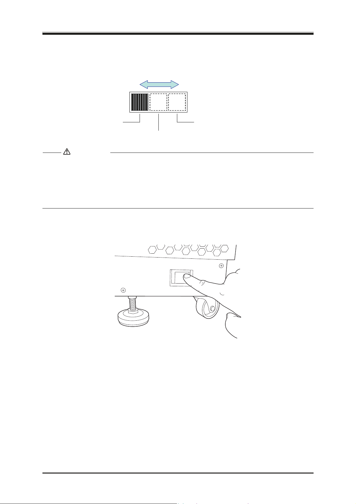
3. Basic Operation
3.2.2 Set the Output Phase Mode (Multi-phase model Only)
Operation procedure
Switch the phase mode setting switch in the power off state depending on the output phase mode.
スイッチをスライド
1φ2W
1φ3W
CAUTION
Set the switch by sliding it.
3φ4W
させて設定する。
Ensure that the power is off when you switch the phase mode setting switch. If the power is
on when you switch the phase mode setting switch, the output phase mode will not be
switched. Also, this operation does not affect the behaviors of the product. If you move the
phase mode setting switch by mistake in the power on state, be sure to move it back to the
original position. Otherwise the product starts up in unexpected output phase mode when at
power-on next time.
3.2.3 Power On
POWER
OFF ON
Press "On" side of the power switch. If you configured a polyphase system, all cabinets need to be
turned on within 20 seconds while the order does not matter.
38
PROGRAMMABLE AC POWER SOURCE
Page 57
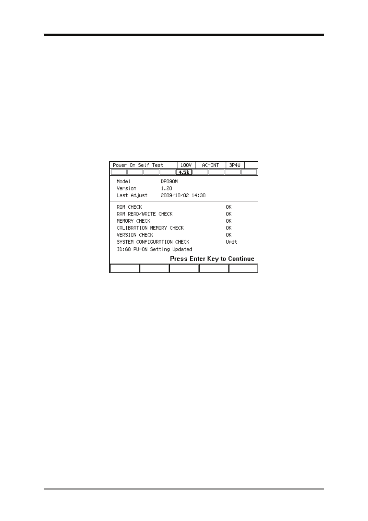
3.2 Power On/Off
3.2.4 Screen Display and Operations at Starting Up
When you power on the cabinet, all LEDs in the control panel illuminate. The LEDs are lighted off
after a while and the following contents are displayed in the order below.
The "NF" logo mark is displayed for a few seconds or more than 10 seconds. The length for
1.
which this logo is displayed depends on your model and system.
The self check is performed and the result is displayed. If any problem is detected, if you
2.
change the polyphase system connection in the single-phase model, or if you change the output
phase mode in the Multi-phase model, the startup process halts in the self check screen shown
in Figure 3–4. Check the self check result and press the ENTER key to resume the startup
process.
Figure 3-4 The Self Check Screen to be Displayed when Starting the Unit in Other
System or in Other Output Phase Mode than before
Depending on the output function selection setting at power-on, the Continuous function screen,
3.
Sequence function screen, or Simulation function screen is displayed. For detailed information
about the output function selection at power-on setting, see
If the output function selection is set to the Continuous function and the output-on at power-on
4.
setting is on, the output is turned on after the confirmation message to inform that the output is
automatically turned on is displayed for about 10 seconds. If you press the ENTER key while
this message is displayed, you can cancel the setting of automatic output-on. For detailed
information about the output-on at power-on setting, see
4.2.10
4.22
and
4.3.10
.
.
3.2.5 The Settings Loaded after Startup
For the Continuous function, the output settings are invoked from the Basic Setting Memory No.1
and other settings are loaded from the System Setting Memory. For details, see 4.8 and 10.24.
F
or the Sequence function and the Simulation function, the factory default settings are loaded for the
content of each step.
If you changed the configuration of a polyphase system or the output phase mode in a Multi-phase
model, the settings are invoked depending on the output phase mode.
DP Series
39
Page 58
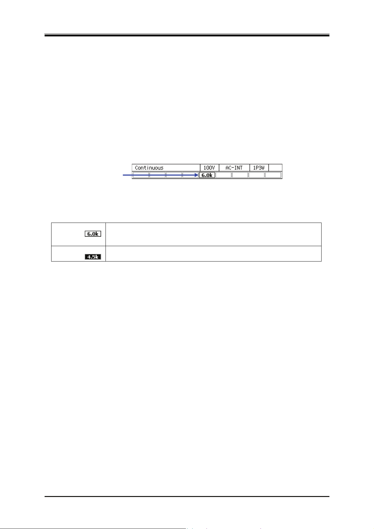
3. Basic Operation
3.2.6 Checking the Rated Power
On the screen after startup, the rated power icon is displayed in the position shown in Figure 3–5.
The value in the icon indicates the maximum electric power that can be output. In Figure 3–5, the
m
aximum electric power is 6.0 kVA.
If the rated power is restricted by the power unit energization setting, the icon is highlighted as
shown in Table 3-4. For detailed information about the power unit energization setting, see 4.24.
I
n some models, the maximum output active power may be restricted when the power supply voltage
is less than or equal to 170 V. In that case, the restricted maximum output active power value is
displayed using the normal icon as shown in Table 3-4. For the restriction applied to the maximum
out
put active power due to the power supply voltage, see 4.1.5.
Rated
定格電力
power icon
アイコン
Figure 3-5 The Rated Power Icon
Table 3-4 How the Rated Power Icon is Displayed Depending on the Power Unit
Energization Setting
Normal icon
Example:
All power unit energization settings are enabled. The rated power is set to
the maximum value that the model system and the power supply voltage can
provide.
Highlighted icon
Example:
Because some power unit energization settings are disabled, the rated power
is restricted.
-------- Notes----------------------------------------------------------------------------------------------------------------
For a polyphase model, the total rated power of all phases is displayed.
For a polyphase system, the rated power is displayed for each phase.
---------------------------------------------------------------------------------------------------------------------------------
3.2.7 Power Off
Disable the output and ensure the OUTPUT LED is off before pressing "Off" side of the power
switch. All screens disappear and all LEDs turn off, then the power input and the output are blocked
inside the system. For a polyphase system, although the order for turning off cabinets is not
significant, a communication error message may appear if the interval between the operations of
turning off the cabinets is too long. This does not cause any problem.
40
PROGRAMMABLE AC POWER SOURCE
Page 59
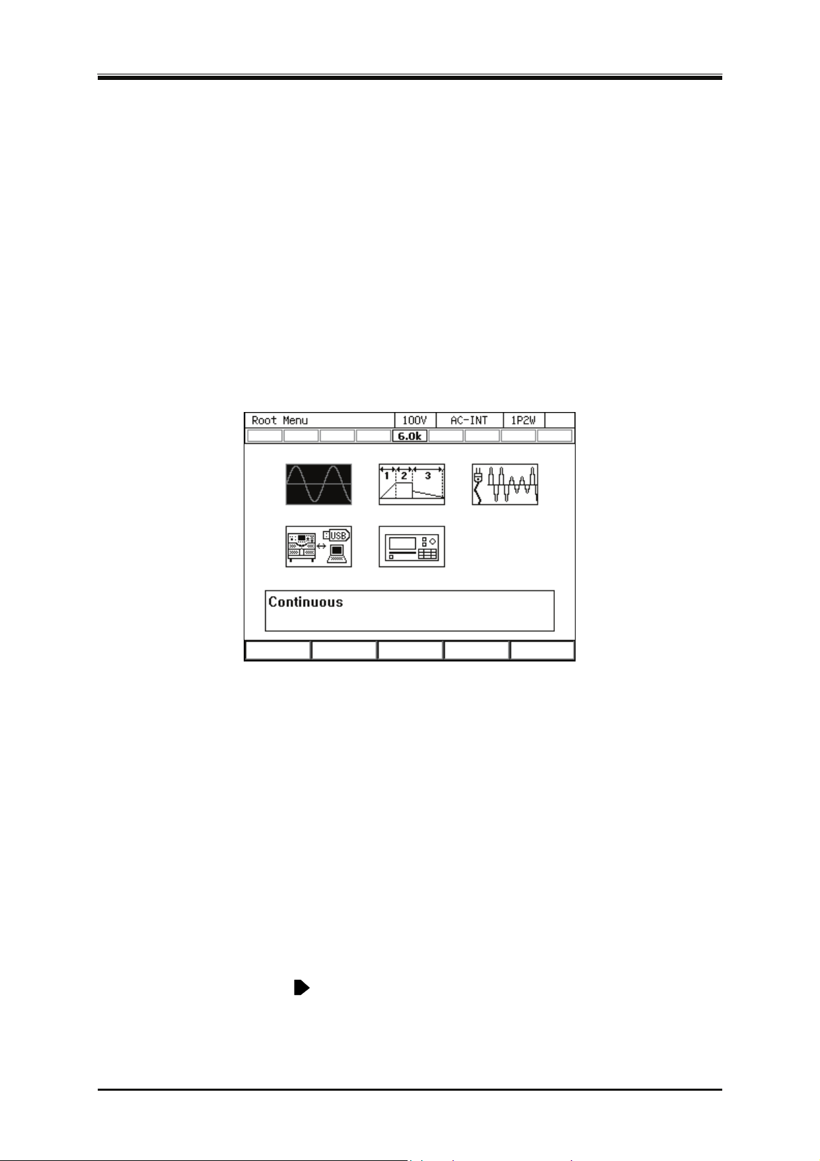
3.3 Basic Key Operations
3.3 Basic Key Operations
3.3.1 Changing the Output Function (Continuous Output/Sequence/Simulation)
To change the Continuous output/Sequence/Simulation function, press the MENU key. This
operation displays the root menu shown in Figure 3–6.
ive icons are available in the root menu. The cursor location is informed by the highlighted icon. The
F
description of the icon at the cursor location is displayed in the box located at the bottom of the screen.
Move the cursor to the function you want to select by using arrow keys or the jog. Each icon in
upper line represents the Continuous output function, Sequence function, and Simulation function
from the left. When you press the ENTER key, the screen for the selected function is displayed. You
cannot change the function in the output on state. However, you can move to the Memory function
screen or System function screen.
Figure 3-6 The Root Menu
3.3.2 Item Selection
You can move the cursor (highlighted icon) by using arrow keys or the jog. However, some items
cannot be selected depending on your model or system. These items are skipped when moving the
cursor. If you press the ENTER key, the item under the cursor is selected and run. If the item is a
menu, the menu screen, window, or selection box is displayed. If you press the CANCEL key, the
menu in the upper hierarchy is displayed without selection or execution of that item.
Selection box
If the menu has numbers before its menu items as shown in Figure 3–7 (selection box ), pressing the
correspond
cursor by using the shuttle.
If you select an item with
displayed. In addition to the ENTER key, you can also use → arrow key to open the selection box of
that menu.
ing number on the numeric keypad also selects and runs the item. You can also move the
on the right, the selection box in the lower hierarchy menu is
DP Series
41
Page 60
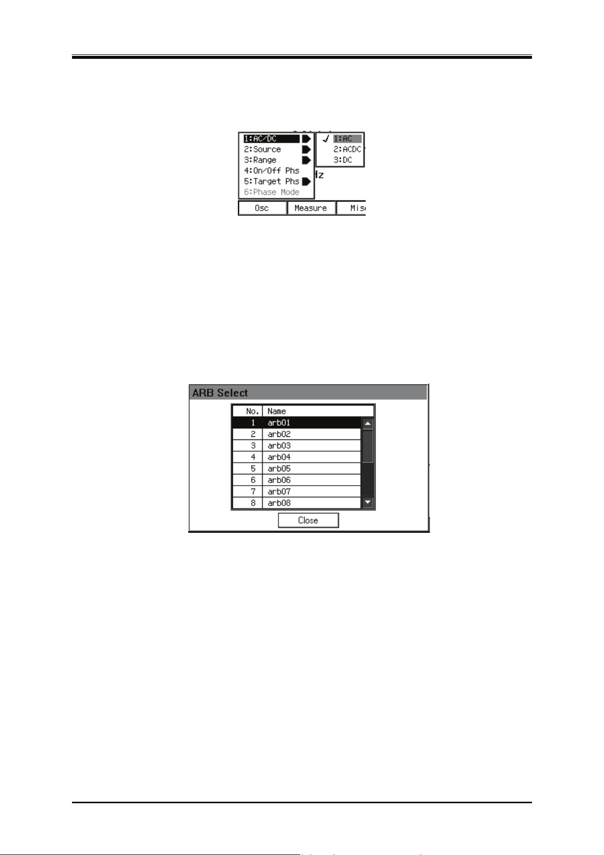
3. Basic Operation
You cannot select grayed items in a selection box, which are different depending on your model or
setting.
Figure 3-7 The Example of a Selection Box
Data list box
When selecting data in the memory, the data list box shown in Figure 3–8 is displayed. To select a
dat
a in a data list box, hover the cursor over the box by using the arrow keys or jog and press the
ENTER key. This operation enables the cursor to move over each data in the data list box. Hover the
cursor over the item you want to select by pressing the up or down arrow key or turning the jog or
shuttle and press the ENTER key.
Figure 3-8 The Example of a Data List Box
3.3.3 Using Soft-keys
When the soft-key function is displayed at the bottom of the LCD screen as shown in Figure 3–9,
pressing a soft-key performs the function assigned to that key.
42
PROGRAMMABLE AC POWER SOURCE
Page 61
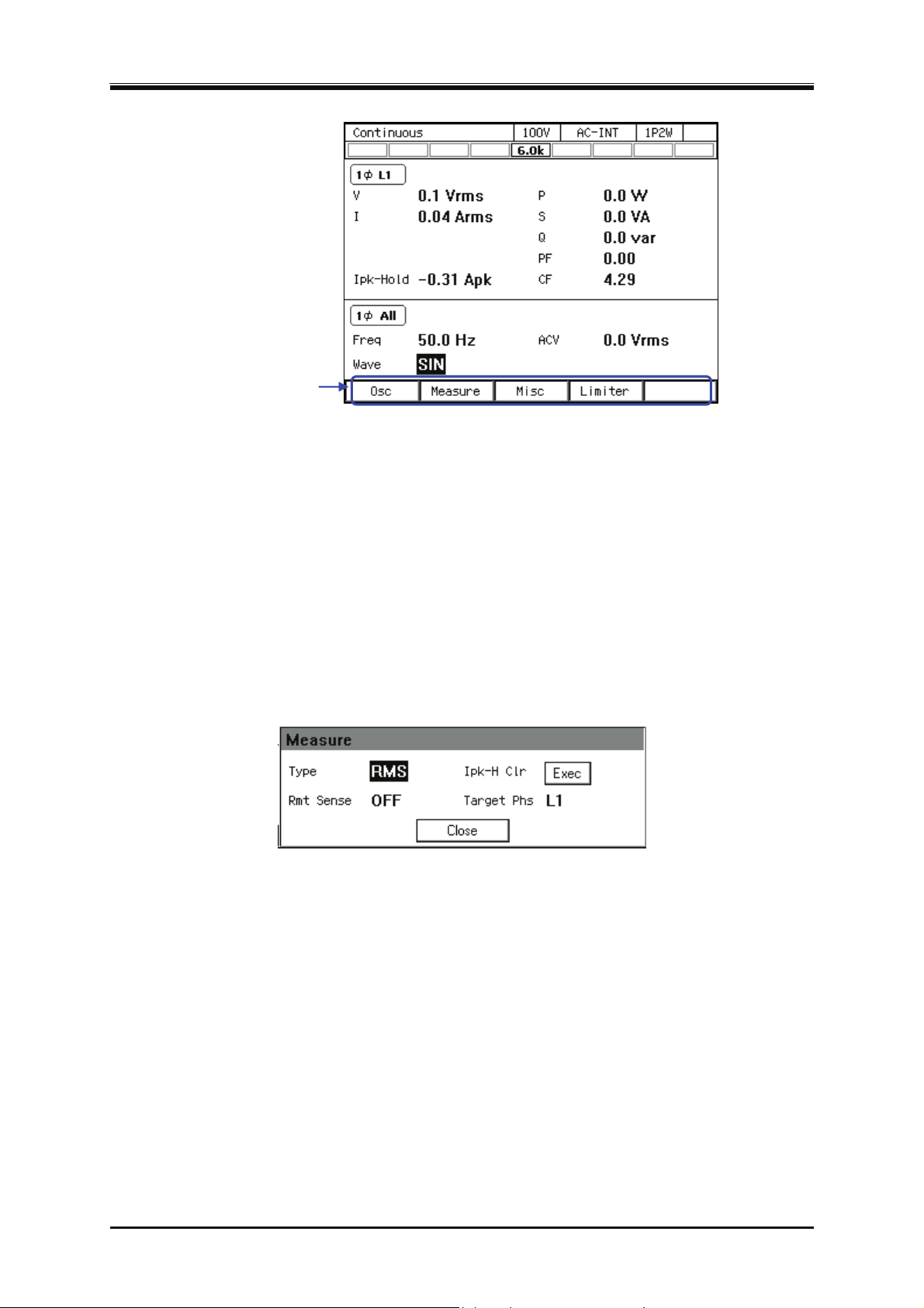
3.3 Basic Key Operations
ソフトキー
Soft-key function
機能
Figure 3-9 Soft-key Function
3.3.4 Closing Windows
The window with the [Close] button
Following three methods are available to close the window with the [Close] button shown in Figure
3–10.
Mov
Press the CANCEL key.
Press the soft-key under the [Close] button (third button from the left).
e the cursor to the [Close] button in the window by using the arrow keys or the jog and
press the ENTER key.
Figure 3-10 The Example of the Window with the [Close] Button
Window with the [OK]/[Cancel] button
Following three methods are available to close the window with the [OK]/[Cancel] button shown in
Figure 3–11.
Mov
e the cursor to the [OK] button or [Cancel] button in the window by using the arrow keys
or the jog and press the ENTER key.
Press the CANCEL key. To do so, perform the same operation as you did to select the [Cancel]
button.
Pressing the soft-key under the [OK] button (fourth button from the left) means same as
selecting the [OK] button. Similarly, pressing the soft-key under the [Cancel] button (second
button from the left) means same as selecting the [Cancel] button.
DP Series
43
Page 62
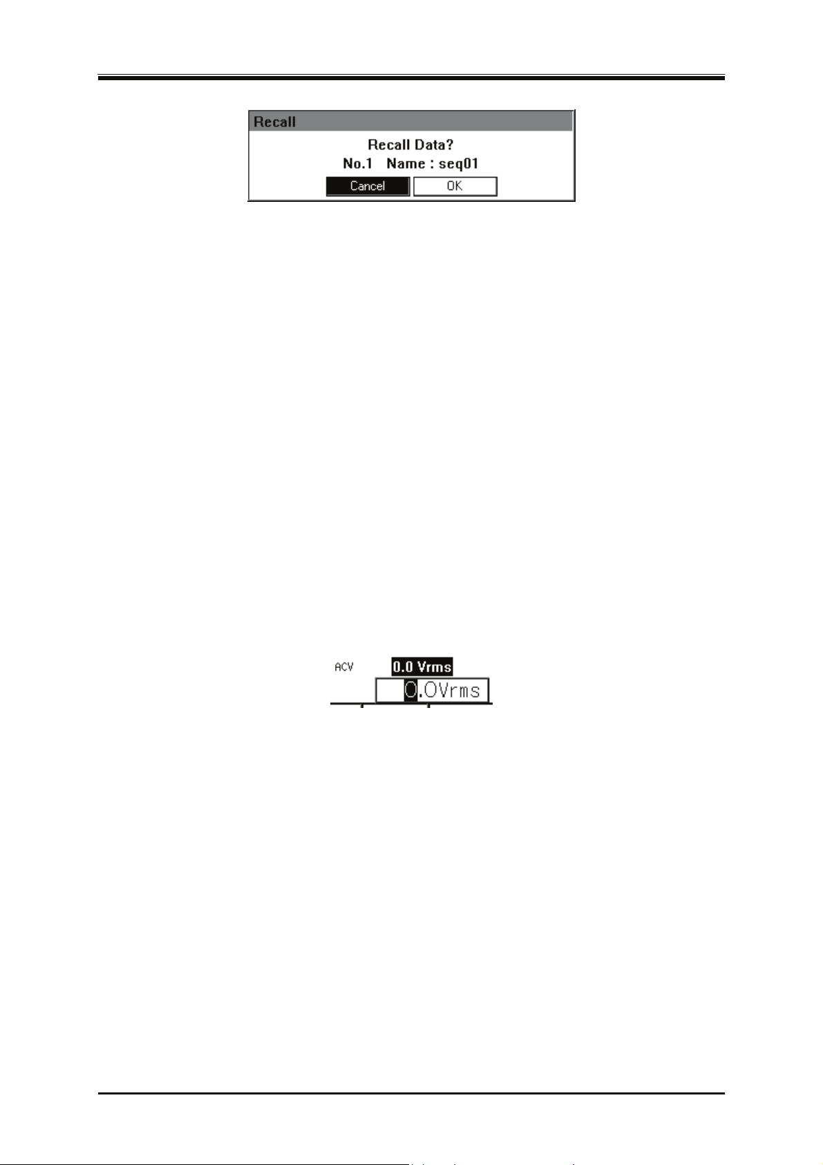
3. Basic Operation
Figure 3-11 The Example of the Window with the [OK]/[Cancel] Button
3.3.5 Entering Values (Numerical Entry Box)
Entering values with arrow keys/jog or shuttle
For an item to set value, hover the cursor over the value (which will be highlighted) and press the
ENTER key to open a numerical entry box shown in Figure 3–12 in which you can enter a value.
ve to the desired digit by using the right or left arrow key and increment/decrement the value by
Mo
using the up or down arrow key/the jog or shuttle. During the edit, the value is confirmed every time
it is incremented or decremented. The value for the voltage or frequency output is applied even
during the edit. If you press the ENTER key or the CANCEL key, the numerical entry box is closed.
Enter values directly by using the numeric keypad
For an item required to set values, hover the cursor over a value (which will be highlighted) and
enter a new value by using the numeric keypad. A numerical entry box opens as you start entering a
value, and the entered value is displayed. Press the ENTER key to confirm the value. The previous
values for the voltage or frequency output are held until you press the ENTER key. If you press the
CANCEL key, the settings are not changed.
Figure 3-12 The Numerical Entry Box
-------- Notes----------------------------------------------------------------------------------------------------------------
If you already know the value to set, the direct entry using the numeric keypad will be
convenient.
If you want to increment/decrement the value by one step at one time, use the up and down
arrow key.
If you want to increment/decrement the value by a large amount step by step, use the jog.
If you want to increment/decrement the value by a large amount quickly, use the shuttle.
---------------------------------------------------------------------------------------------------------------------------------
3.3.6 Entering Strings (Character String Entry Box)
Enter the name of the data when saving it to the internal memory or USB memory. In this case,
hover the cursor over the string (which will be highlighted) and press the ENTER key. This
44
PROGRAMMABLE AC POWER SOURCE
Page 63
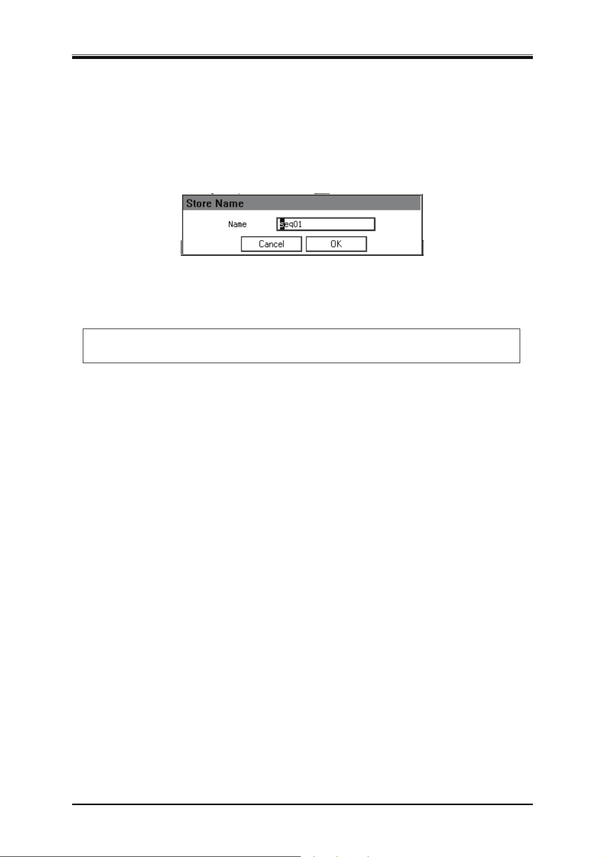
3.3 Basic Key Operations
operation opens a character string entry box shown in Figure 3–13.
When you turn the jog or press the up or down arrow key in a character string entry box, the
character at the cursor (highlighted character) is changed in a way shown in Table 3-5. When you
press a ke
y in the numeric keypad, the corresponding value or symbol is entered. To move the cursor
position, use the right or left arrow key. When you press the ENTER key, the edited string is
confirmed and the character string entry box is closed.
Figure 3-13 Character String Entry Box
Table 3-5 Character String Entry List
← Turning the jog in the counterclockwise direction
Pressing the down arrow key
Turning the jog in the clockwise direction
Pressing the up arrow key →
ABCDEFGHIJKLMNOPQRSTUVWXYZabcdefghijklmnopqrstuvwxyz
0123456789!#$%&'()+,-.;=@[]^_`{}~
(Note) indicates a space.
-------- Notes----------------------------------------------------------------------------------------------------------------
The name of the data which will be saved in the internal memory or USB memory must be 20
characters long at a maximum.
---------------------------------------------------------------------------------------------------------------------------------
DP Series
45
Page 64
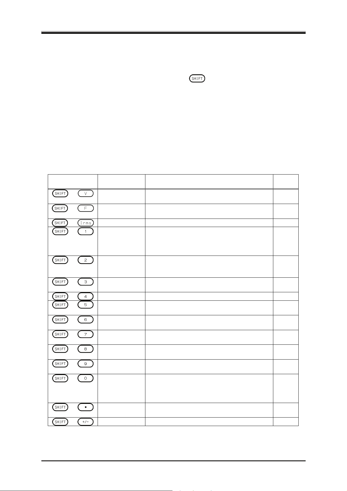
3. Basic Operation
3.3.7 Using Shortcut Operations (SHIFT Key)
When you press the SHIFT key, the SHIFT LED illuminates. In this state (shift state), pressing one
of the V, F, I, and any keys in the numeric keypad enables shown in Table 3-6. In this instruction
m
anual, pressing a key in the shift state is denoted by "
If you press the SHIFT key once more in the shift state, the SHIFT LED is lighted off and the shift
state exits.
-------- Notes----------------------------------------------------------------------------------------------------------------
The shift state is kept until you press the SHIFT key next time. Therefore, continuous Shortcut
operations can be performed.
You do not have to hold down the SHIFT key while you press another key.
---------------------------------------------------------------------------------------------------------------------------------
Table 3-6 Shortcut Operations
Shortcut Item Description Refer
+
V-LIMIT Opens the setting window for the voltage setting
range limit.
+
F-LIMIT Opens the setting window for the frequency
setting range limit.
+
+
Ipk-LIMIT Opens the peak current limiter set window.
S-L1/L2/L3
†
Switches the target phase to be configured in
the following order: L1, L2, L3 (unbalanced
mode), All Phase, and All Line (balanced
mode).
+
M-L1/L2/L3
†
Switches the target phase of which the
measured value is displayed in the following
order: L1, L2, L3 ,L1-L2, L2-L3, L3-L1.
+
RMS/AVG/PK
†
Switches the display format of the measured
value in the following order: RMS, AVG, PK.
+
+
+
KEY LOCK Enables/Disables the key lock.
AGC/Acal Opens the AGC/Autocal set window. 4.12,
USB-EJECT Performs the eject operation for removing a
USB memory.
+
AC/DC Switches the AC/DC mode in the following
order: AC, ACDC, DC.
+
SOURCE Switches the signal source in the following
order: INT, VCA, SYNC, EXT, ADD.
+
CONTRAST Changes to the state in which the contrast is
selected in the LCD set window.
+
LOCAL Exits the Remote state between the device
connected to the communication interface and
enters the Local state in which the panel
operations are accepted.
+
DISP Switches the measured value display mode
between normal and simple.
+
Note: If you change the item presented with † symbol using a Shortcut operations, the setting is not saved in the
System Setting Memory (see
Ipk CLR Clears the current peak-hold value.
10.24).
+ X."
to
4.1.3
4.1.4
4.1.1
3.4.5,
4.15
3.4.13
3.4.10
4.25
4.13
4.9
3.4.1
3.4.1
4.27
6.2
3.4.11
3.4.12
46
PROGRAMMABLE AC POWER SOURCE
Page 65
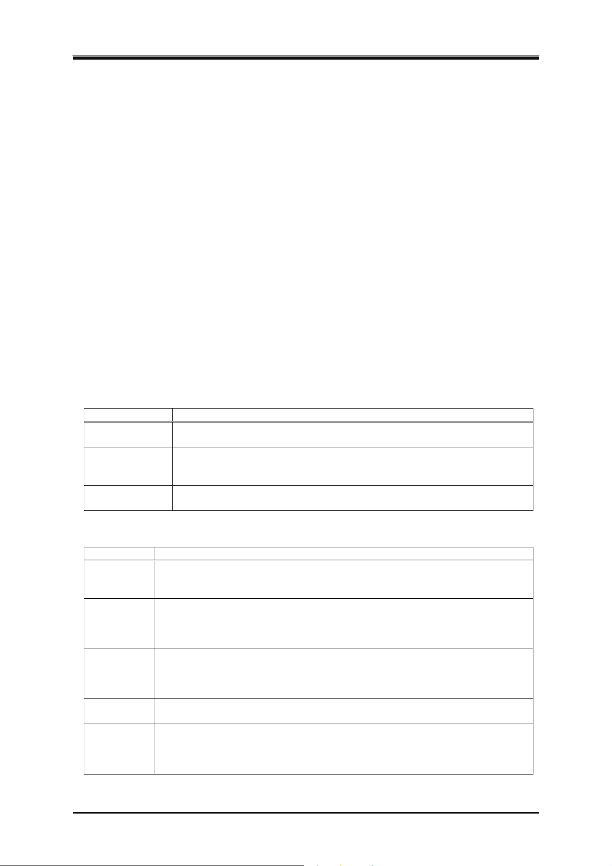
3.4 Using the Continuous Function
3.4 Using the Continuous Function
3.4.1 Setting the AC/DC Mode and the Signal Source
The description of the AC/DC mode is shown in Table 3-7. The description of the signal source is
shown in Table 3-8. The selectable combinations of the AC/DC mode and the signal source is shown
in
Table 3-9.
-------- Not
If the load is a transformer whose core saturates even with small amount of DC component,
If you output AC less than 40 Hz, select the ACDC mode. You cannot set the frequency to less
In the AC mode, if the output is a waveform that has a long cycle or is dissymmetric in terms
---------------------------------------------------------------------------------------------------------------------------------
es----------------------------------------------------------------------------------------------------------------
select the AC mode.
than 40 Hz in the AC mode.
of positive and negative (e.g. when the phase is changed rapidly or the different values are set
for the positive and negative in the peak current limiter), the waveform may be transformed by
the DC component removing function of the AC mode. If you want to make the output
waveform similar to the signal source, select the ACDC mode.
Table 3-7 Description of the AC/DC Mode
AC/DC mode Description
AC Only the AC voltage can be set. The AC coupling is used between the signal
source and the amplification section and the DC component is removed.
ACDC The AC voltage and the DC voltage can be set respectively. The DC coupling
is used between the signal source and the amplification section and both of
the AC component and the DC component are output.
DC Only the DC voltage can be set; the AC voltage is fixed to zero. The DC
coupling is used between the signal source and the amplification section.
Table 3-8 The Description of the Signal Source
Signal source Description
INT The signal source is internal. Set the output voltage, output waveform, frequency,
output on phase, and output off phase through the control panel or the remote
control.
VCA The signal source is internal. The output voltage can be controlled with the
external DC input signal. The output voltage setting cannot be set through the
control panel or the remote control. All conditions except for output voltage
setting is same as INT.
SYNC The signal source is internal. The frequency of the internal signal source is
synchronized with the external input signal or the power line. The frequency
setting cannot be set through the control panel or the remote control. All
conditions except for output frequency setting is same as INT.
EXT† The signal source is external. Outputs the amplified external input signal. Set the
voltage gain through the control panel or the remote control.
ADD† The signal source is the total of the external and the internal signal source. Set the
voltage gain for the external input signal, output voltage for the internal signal
source, output waveform, frequency, output on phase, and output off phase
through the control panel or the remote control.
Note: † indicates an option.
DP Series
47
Page 66
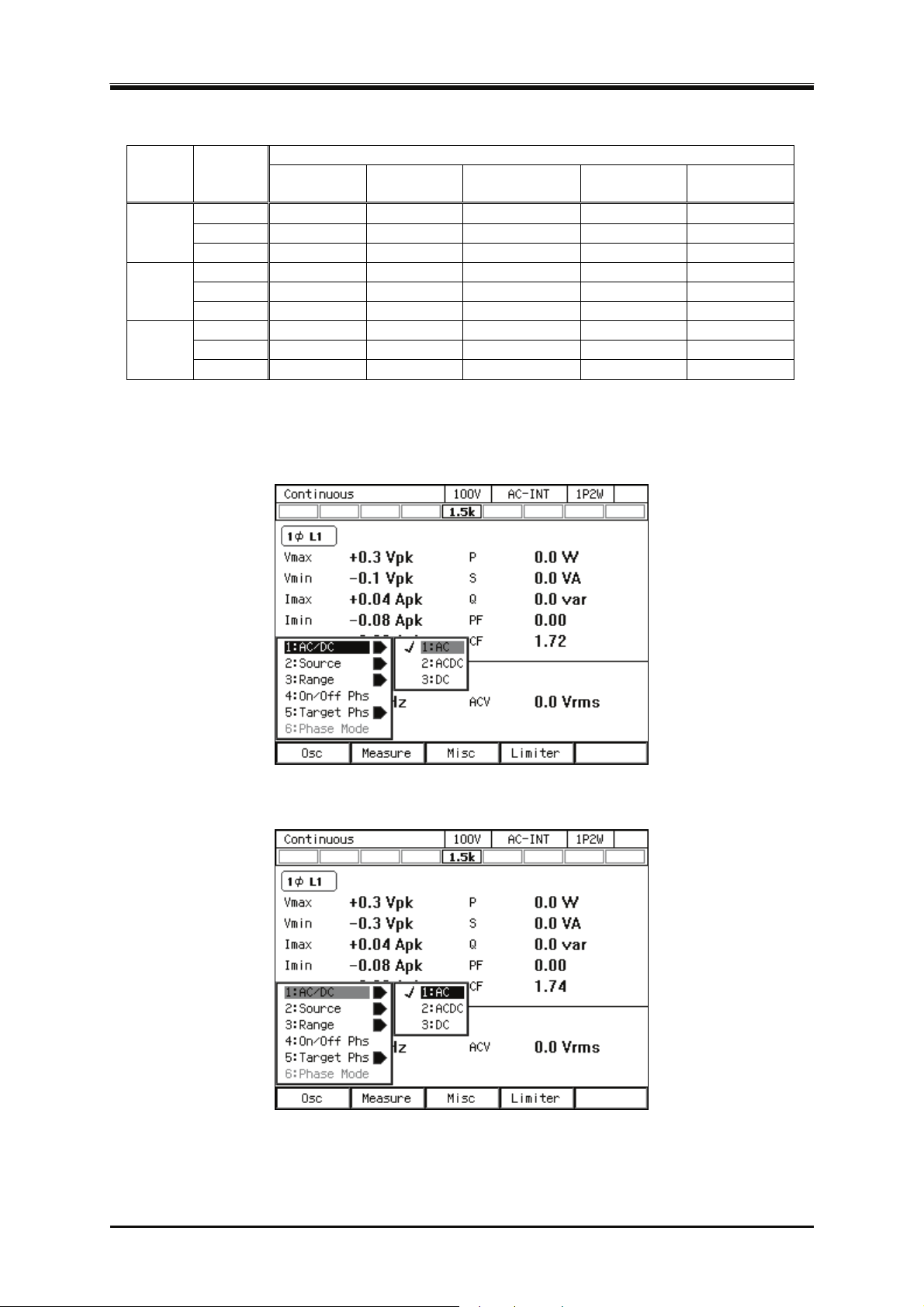
3. Basic Operation
Table 3-9 List of the Selectable Combinations of the AC/DC Mode and the Signal Source
Output
phase
mode
1P2W
AC/DC
mode
INT VCA SYNC EXT ADD
AC AC-INT AC-VCA AC-SYNC AC-EXT AC-ADD
Signal source
ACDC ACDC-INT - ACDC-SYNC ACDC-EXT ACDC-ADD
DC DC-INT DC-VCA - - -
1P3W
AC AC-INT AC-VCA AC-SYNC - -
ACDC*1 ACDC-INT - ACDC-SYNC - -
DC - - - - -
3P4W
AC AC-INT AC-VCA AC-SYNC - -
ACDC*1 ACDC-INT - ACDC-SYNC - -
DC - - - - -
*1: The DC voltage cannot be set in 1P3W or 3P4W of the ACDC mode.
Operation procedures using soft-keys
Press the [Osc] soft-key and select [1:AC/DC].
1.
In the displayed selection box, select the desired AC/DC mode.
2.
48
PROGRAMMABLE AC POWER SOURCE
Page 67
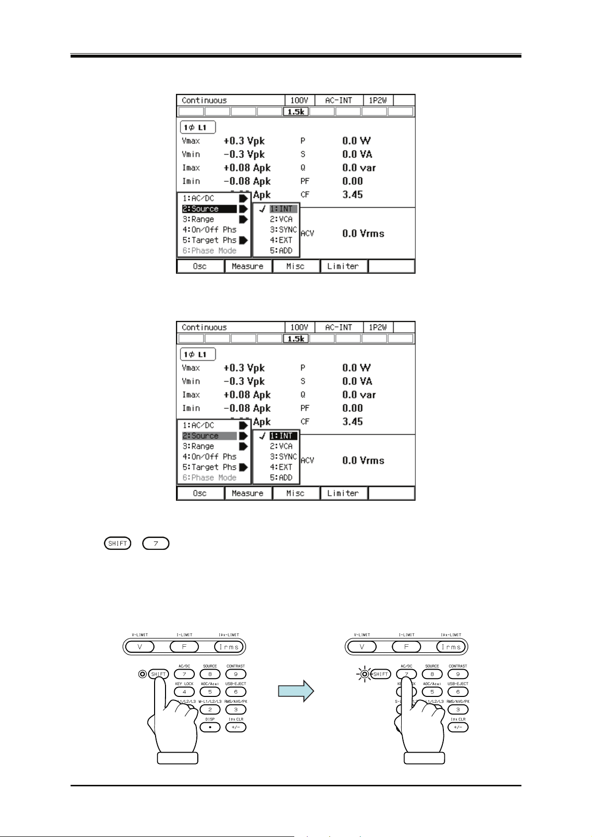
3.4 Using the Continuous Function
Press the [Osc] soft-key and select [2:Source].
3.
In the displayed selection box, select the desired signal source.
4.
Operation procedures by using shortcuts
1.
+ Switching the AC/DC mode
Press the SHIFT key to enter the shift state (the SHIFT LED illuminates). When you press the 7
key of the numeric keypad during the shift state, the AC/DC mode is switched in the following
order: AC, ACDC, DC, AC. Some modes may be skipped and cannot be selected depending on
the signal source.
DP Series
49
Page 68
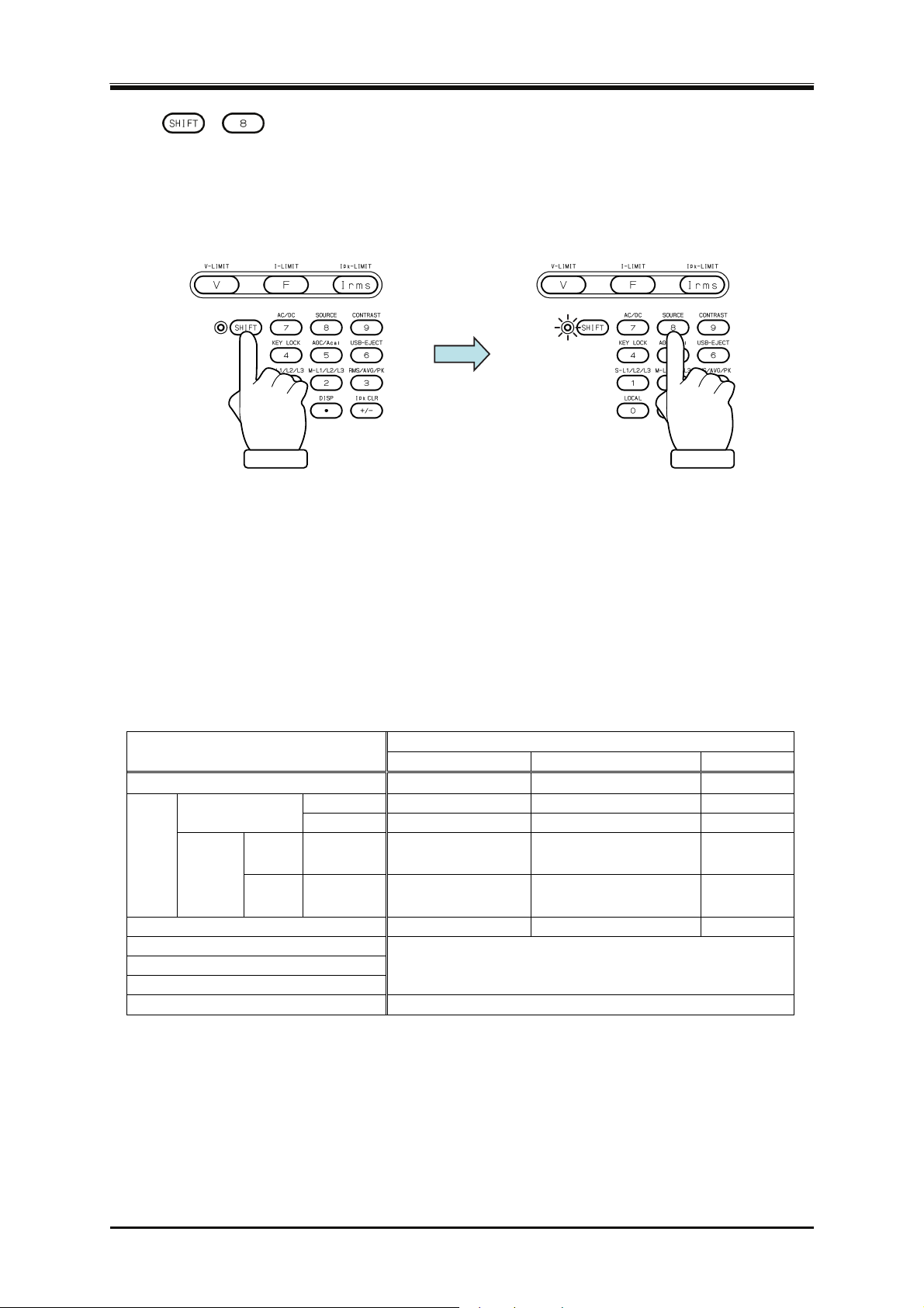
3. Basic Operation
2.
+ Switching the signal source
Press the SHIFT key to enter the shift state (the SHIFT LED illuminates). When you press the 8
key of the numeric keypad during the shift state, the signal source is switched in the following
order: INT, VCA, SYNC, EXT, ADD, INT. Some signal sources may be skipped and cannot be
selected depending on the AC/DC mode.
3.4.2 Setting the Output Range
You can select the 100 V range or 200 V range. Table 3-10 shows the setting range for each range.
-------- Not
You cannot switch the output range in the output on state.
---------------------------------------------------------------------------------------------------------------------------------
es----------------------------------------------------------------------------------------------------------------
Table 3-10 The Setting Range per Output Range
Setting Item
DC voltage
voltage
Phase Voltage
AC
Line
voltage
External Input Gain 0.0 to 220.0 0.0 to 440.0 Times
Peak current limiter (positive)
Peak current limiter (negative)
RMS current limiter
Voltage Setting Limit Refer to 10.14
1P3W SIN 0.0 to 310.0 0.0 to 620.0 Vrms
3P4W SIN 0.0 to 268.4 0.0 to 536.8 Vrms
Setting Range
100 V range 200 V range Unit
−220.0 to +220.0 −440.0 to +440.0
SIN, CLP 0.0 to 155.0 0.0 to 310.0 Vrms
ARB 0.0 to 440.0 0.0 to 880.0 Vp-p
Refer to 10.13
V
50
PROGRAMMABLE AC POWER SOURCE
Page 69
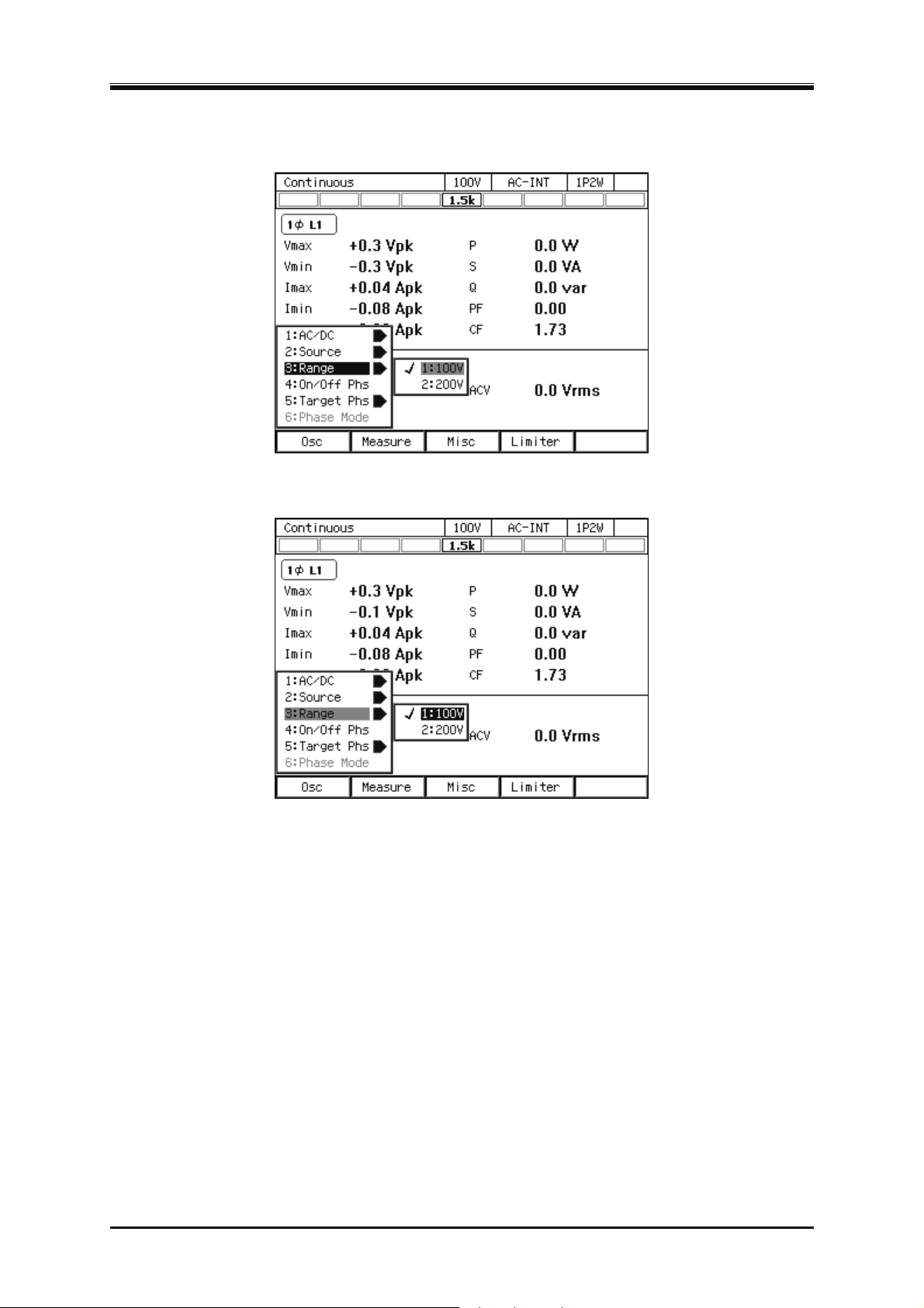
Operation procedures using soft-keys
Press the [Osc] soft-key and select [3:Range].
1.
In the displayed selection box, select the desired output range.
2.
3.4 Using the Continuous Function
Operation procedures using the RANGE key
The range is toggled between 100 V range and 200 V range every time you press the RANGE key.
3.4.3 Setting Waveforms
You can select a waveform of the internal signal source from sine wave (SIN), clipped sine wave
(CLP, three types available), and arbitrary waveform (ARB, 16 types available). See 4.6 for de
on the clipped sine wave, and 4.7 on t
DP Series
he arbitrary waveform.
tails
51
Page 70
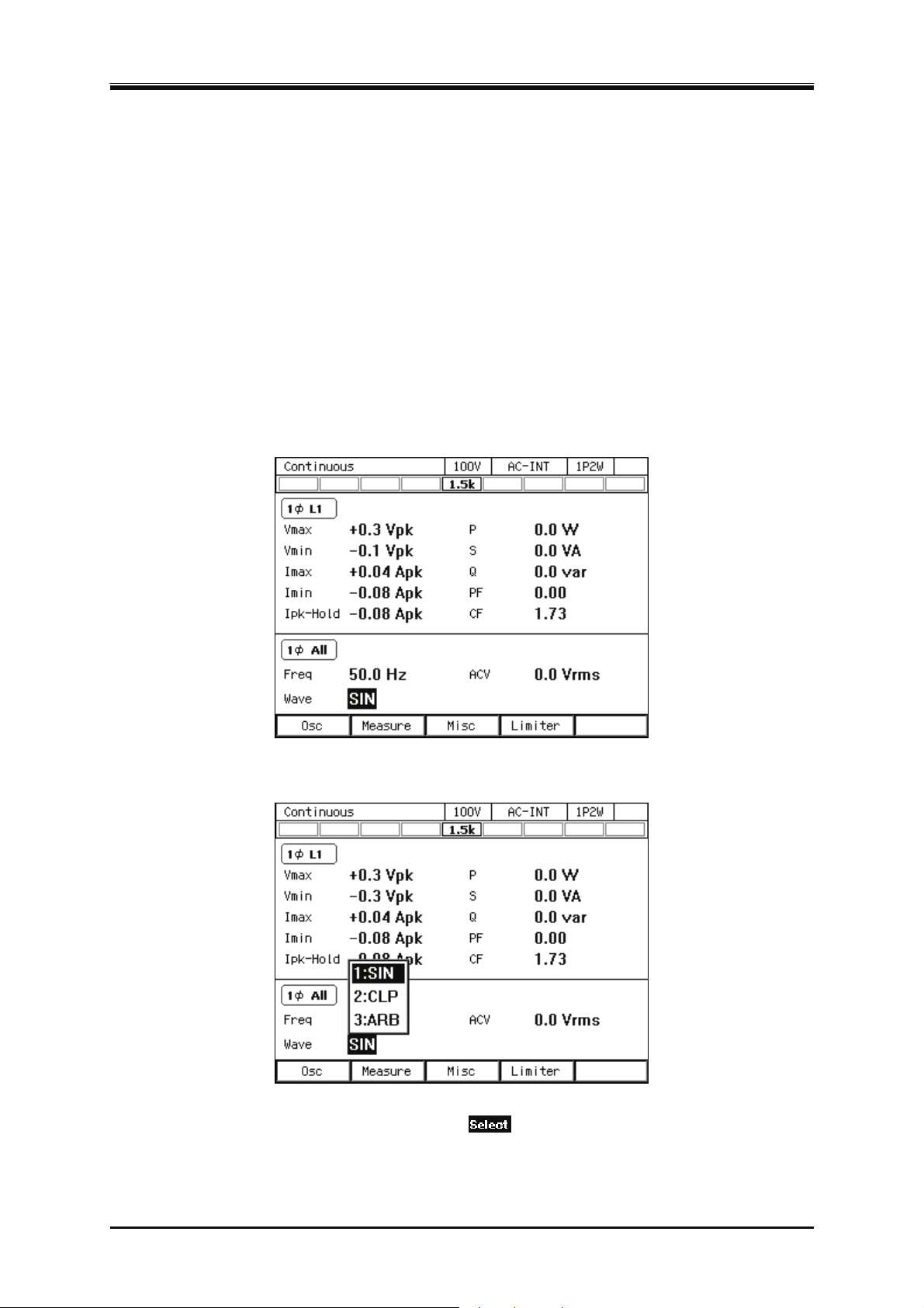
3. Basic Operation
-------- Notes----------------------------------------------------------------------------------------------------------------
The AC voltage setting (ACV) is common between SIN and CLP, but ARB is independent of
these. When you switch the waveform selection among SIN, CLP, and ARB, the AC voltage
setting is also switched. The DC output voltage setting (DCV) is same regardless of the
waveform setting.
The waveform can be changed in the output on state, but the AC output voltage setting (ACV)
is also switched as described above if you switch the waveform selection between SIN, CLP,
and ARB. Set ACVs for SIN, CLP, and ARB in the output off state before you change the
waveform in the output on state.
---------------------------------------------------------------------------------------------------------------------------------
Operation procedure
Select the [Wave] item.
1.
In the displayed selection box, select the desired waveform (SIN, CLP, ARB).
2.
If you select CLP or ARB, the [Select] icon (
3.
) is displayed next to it. When you hover the
cursor over the [Select] icon, the clip ratio or crest factor is displayed for the clipped sine wave,
or the arbitrary waveform data name for the arbitrary waveform. When you press the ENTER
52
PROGRAMMABLE AC POWER SOURCE
Page 71
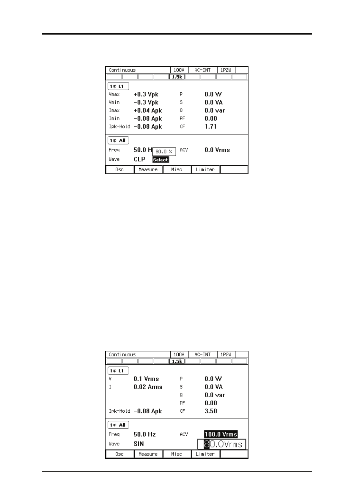
3.4 Using the Continuous Function
key, the setting window opens for the clipped sine wave or the selection window opens for the
arbitrary waveform. In this window, set or select items as needed.
3.4.4 Setting the Output Voltage (Single-phase Output)
Set the AC component and DC component separately for the output voltage of the internal signal
source. For the AC component, set the output voltage in the ACV item.For the DC component, set it
inthe DCV item.
-------- Notes----------------------------------------------------------------------------------------------------------------
The output voltage setting is common between SIN and CLP, but ARB is independent of these.
When you switch the waveform setting among SIN, CLP, and ARB, the output voltage setting
is also switched.
In the ACDC mode, the voltage setting range limit is applied to the additional values of the AC
voltage setting (recalculated to a peak value) and the DC voltage setting. For details, see
4.1.3.
---------------------------------------------------------------------------------------------------------------------------------
Operation procedures for setting the AC voltage
Select the [ACV] item and then enter a numeric value. For how to enter values, see
1.
3.3.5
.
DP Series
53
Page 72
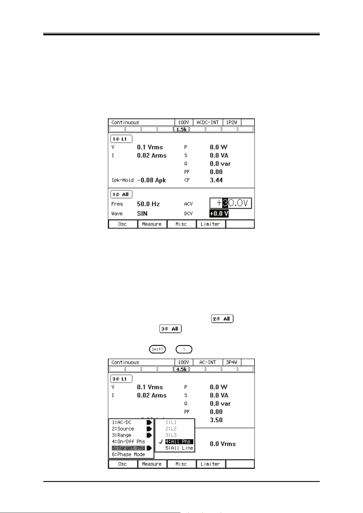
3. Basic Operation
-------- Notes----------------------------------------------------------------------------------------------------------------
Set the RMS values for the voltages of the sine wave (SIN) and the clipped sine wave (CLP)
and the Peak-to-Peak value for the voltage of the arbitrary waveform (ARB).
---------------------------------------------------------------------------------------------------------------------------------
Operation procedures for setting the DC voltage
Select the [DCV] item and then enter a numeric value. For how to enter values, see
1.
3.3.5
.
3.4.5 Setting the Output Voltage (Polyphase Output)
This section describes the operations in the balanced mode in a polyphase model and a polyphase
system. In the balanced mode, the phase voltage and the line voltage are set for all phases at once.
To enter the balanced mode, select the [Osc] soft-key → [6: Phase Mode] to open the phase mode set
window, and select [1:Balance] in the Mode item. For details on the unbalanced mode, see 4.15.
O
peration procedures for setting the phase voltage
Check the icon in the output display area (see
1.
or single-phase three-wire system)/
different icon is shown, press the [Osc] soft-key and select [5:Target Phs] → [4:All Phs]. Or
perform the Shortcut operation
+ to switch to [All Phs].
) is
5.1
(three-phase model or three-phase system). If the
(single-phase three-wire model
54
PROGRAMMABLE AC POWER SOURCE
Page 73
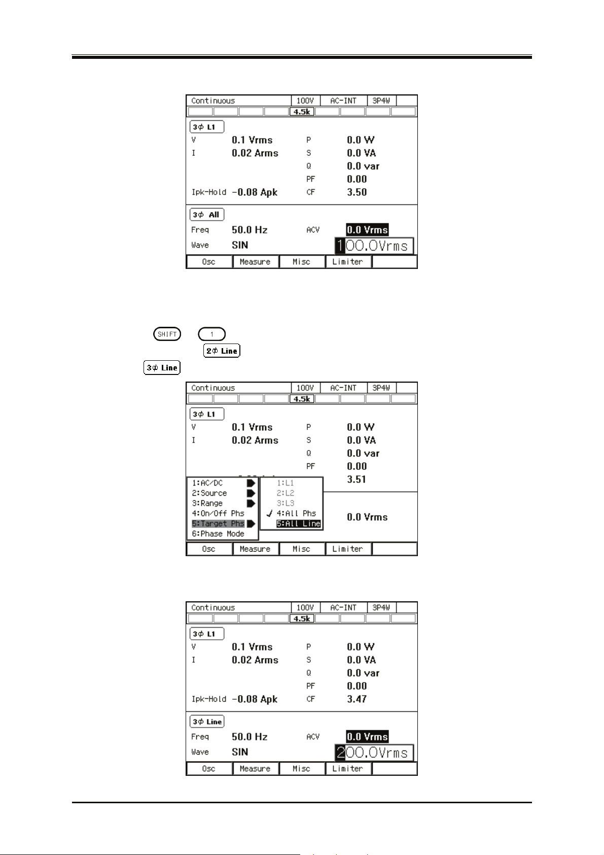
3.4 Using the Continuous Function
Select the [ACV] item and then enter a numeric value. For how to enter values, see
2.
Operation procedures for setting the line voltage
Press the [Osc] soft-key and select [5:Target Phs] → [5:All Line]. Or perform the Shortcut
1.
operation
area (see
system)/
+ to switch to [All Line]. Check that the icon in the output display
5.1
) i
s
(single-phase three-wire model or single-phase three-wire
(three-phase model or three-phase system).
.
3.3.5
Select the [ACV] item and then enter a numeric value. For how to enter values, see
2.
DP Series
.
3.3.5
55
Page 74
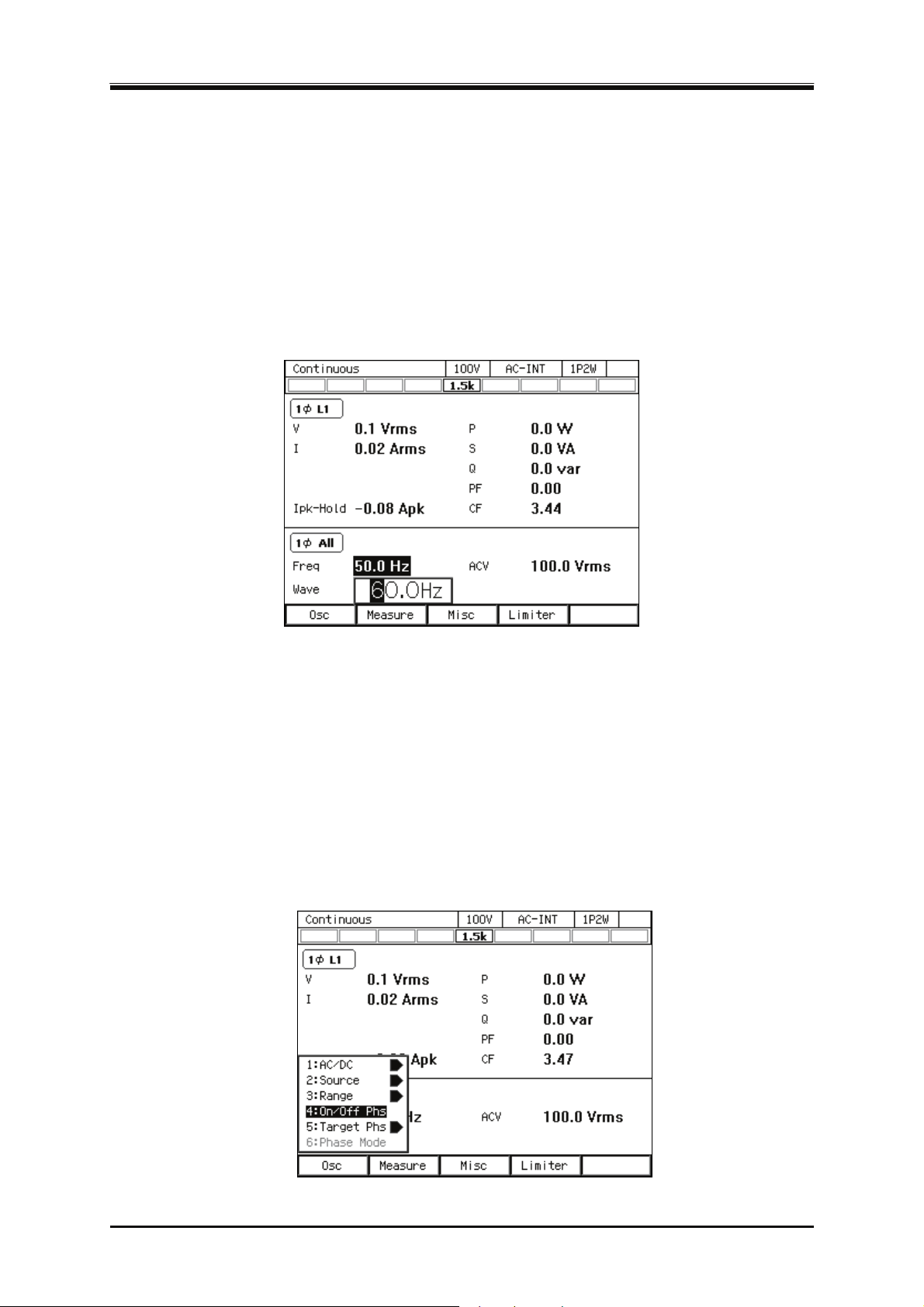
3. Basic Operation
-------- Notes----------------------------------------------------------------------------------------------------------------
The line voltage can be set only for the sine wave in the balanced mode.
---------------------------------------------------------------------------------------------------------------------------------
3.4.6 Setting the Output Frequency
Set the AC component frequency of the internal signal source.
Operation procedure
Select the [Freq] item and follow the instructions in
1.
3.3.5
to
enter a value.
3.4.7 Setting the Output On/Off Phase
Set the phases when the output turns on/off. After the output-on operation, the voltage output is
started from the output on phase. After the output off operation, the voltage output is completed
when it reaches the output off phase. The output off phase can be disabled. If disabled, the output is
turned off immediately after the operation of output off.
Operation procedure
Press the [Osc] soft-key and select [4:On/Off Phs]. The output on/off phase setting window
1.
opens.
56
PROGRAMMABLE AC POWER SOURCE
Page 75
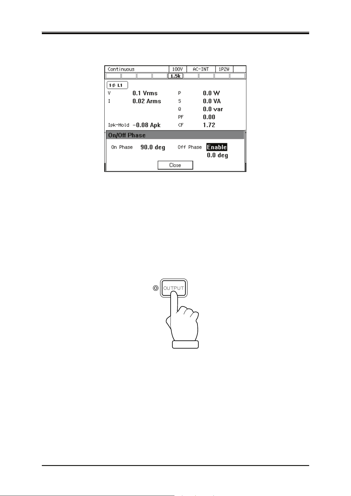
3.4 Using the Continuous Function
Set the on and off phase in the [On Phase] item and [Off Phase] item respectively. If you want
2.
to disable the off phase, select [Disable].
Close the window. For how to close the window, see
3.
3.3.4
.
-------- Not
es----------------------------------------------------------------------------------------------------------------
The output on/off phase setting is invalid for the Sequence and the Simulation.
---------------------------------------------------------------------------------------------------------------------------------
3.4.8 Turning the Output On or Off
Use the OUTPUT key to turn the output on or off. The OUTPUT LED illuminates in the output on
state.
-------- Notes----------------------------------------------------------------------------------------------------------------
For how to turn the output on or off rapidly, see 4.21.
---------------------------------------------------------------------------------------------------------------------------------
DP Series
57
Page 76
3. Basic Operation
3.4.9 Using the Measurement Function
The measured values are displayed in the measured value area (see 5.1). The main measurement
functions of this product are shown in Table 3-11. For details of the display items of the measured
va
lue, see 5.1.2.
Tabl
e 3-11 Main Measurement Functions
Item Description Unit
V Output voltage effective
value
Vavg Output voltage average
value
Vmax Output voltage maximum
peak value
Vmin Output voltage minimum
peak value
I Output RMS current The effective (RMS) value of the output
Iavg Output current average
value
Imax Output current maximum
peak value
Imin The minimum peak value
of the output current
Ipk-Hold Output current peak-hold
value
P Active power The active power provided to the load.
S Apparent power The apparent power provided to the load.
Q Reactive power The reactive power provided to the load.
The effective (RMS) value of the output
voltage on the output terminal.
The average DC value of the output
voltage on the output terminal.
The maximum peak value of the output
voltage on the output terminal.
The minimum peak value of the output
voltage on the output terminal.
voltage. When the line voltage display is
L1-L2/L2-L3/L3-L1, the phase current of
the L1/L2/L3 phase is displayed
respectively.
The average DC value of the output
current.
The maximum peak value of the output
current. When the line voltage display is
L1-L2/L2-L3/L3-L1, the phase current of
the L1/L2/L3 phase is displayed
respectively.
The minimum peak value of the output
current. When the line voltage display is
L1-L2/L2-L3/L3-L1, the phase current of
the L1/L2/L3 phase is displayed
respectively.
The hold value of Imax or Imin, either of
which the value is bigger. When the line
voltage display is L1-L2/L2-L3/L3-L1,
the phase current of the L1/L2/L3 phase
is displayed respectively.
The power of the phase is displayed when
in the phase voltage display. The total
power of all phases is displayed when in
the line voltage display.
The power of the phase is displayed when
in the phase voltage display. The total
power of all phases is displayed when in
the line voltage display.
The power of the phase is displayed when
in the phase voltage display. The total
power of all phases is displayed when in
the line voltage display.
Vrms
V
Vpk
Vpk
Arms
A
Apk
Apk
Apk
W
VA
var
58
PROGRAMMABLE AC POWER SOURCE
Page 77
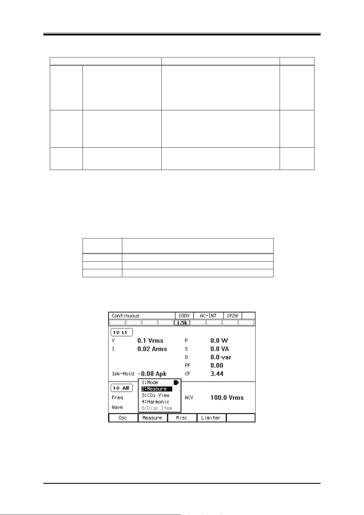
3.4 Using the Continuous Function
Table 3-11 Main Measurement Functions (continued)
Item Description Unit
PF Power factor The power factor of the load. The power
—
factor of the phase is displayed when in
the phase voltage display in the
polyphase model and polyphase system.
It is not displayed when in the line
voltage display.
CF Crest factor The crest factor of the output current
—
(peak value/effective value). It is not
displayed for the line voltage display in
the polyphase model and polyphase
system.
F Synchronization frequency The measured frequency value of the
Hz
synchronization signal source when the
signal source is SYNC.
3.4.10 Switching the Display Format (RMS/AVG/Peak) of the Measured Value
You can switch the display format of the measured value (RMS/AVG/Peak) for the output voltage
and output current. The items which are displayed in each measuring mode are shown in Table 3-12.
Tabl
e 3-12 The Measuring Mode for the Measured Values of the Output Voltage and
Output Current
Measuring
mode
(Output Voltage, Output Current)
RMS V, I, Ipk-Hold
AVG Vavg, Iavg, Ipk-Hold
Peak Vmax, Vmin, Imax, Imin, Ipk-Hold
Operation procedures using soft-keys
Press the [Measure] soft-key and select [2:Measure]. The [Measure] window opens.
1.
Items to be Displayed
DP Series
59
Page 78
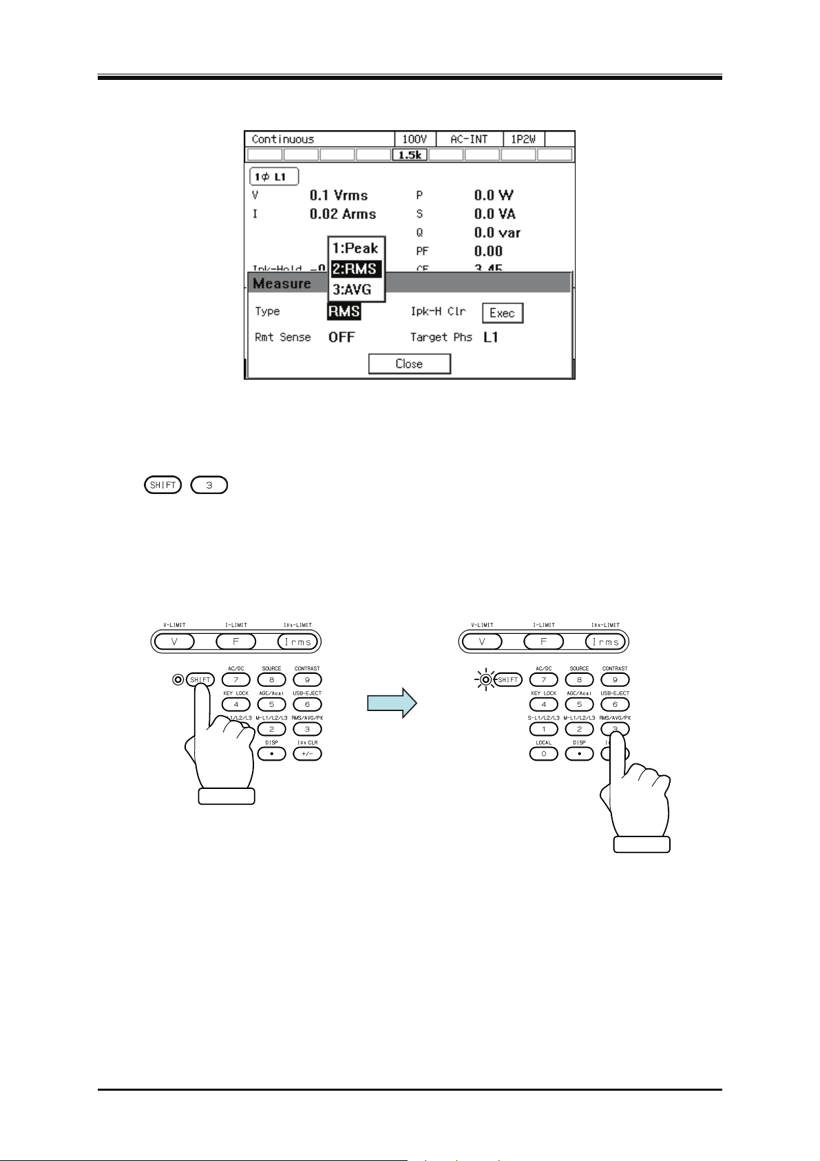
3. Basic Operation
Select the [Type] item. In the displayed selection box, select the desired measuring mode.
2.
Close the window. For how to close the window, see
3.
peration procedures by using shortcuts
O
1.
+ Switching the display format of the measured values
Press the SHIFT key to enter the shift state (the SHIFT LED illuminates). When you press the 3
key of the numeric keypad during the shift state, the measuring mode is switched in the
following order: RMS, AVG, Peak, RMS. Some measuring modes may be skipped and cannot
be selected depending on the AC/DC mode.
3.3.4
.
60
PROGRAMMABLE AC POWER SOURCE
Page 79
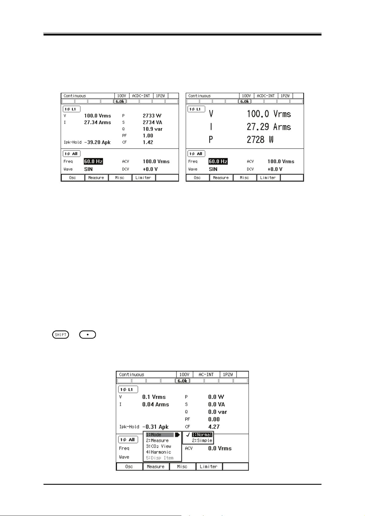
3.4 Using the Continuous Function
3.4.11 Enlarge Display Letters for the Measured Value
You can switch the measured value display mode between normal (normal) and the mode in which the
letters are enlarged (simple) shown in Figure 3–14. In the Simple View mode, three types of measured
v
alues are displayed. You can select the measured value being displayed in the Simple View mode.
Figure 3-14 The Normal View (left) and the Simple View Mode (right)
-------- Notes----------------------------------------------------------------------------------------------------------------
If the measured value display mode is changed to Peak in the Simple View mode, the
maximum peak values (Vmax/Imax) are displayed instead of the voltage/current measured
value. Also, if the measured value display mode is changed to RMS/AVG from Peak, the
effective/average values are displayed instead of the maximum and minimum peak values.
If the AC/DC mode and the signal source are changed in the Simple View mode, the measured
voltage values are forced to be displayed instead of the items that are not displayed in the mode after
the change, such as the power factor or crest factor. If this operation is applied to multiple items, the
measured current value is displayed for the second item, and the current peak-hold value for the third.
---------------------------------------------------------------------------------------------------------------------------------
Switching the measured value display mode (normal/simple)
The mode is toggled between normal and simple every time you perform the Shortcut operation with
+ . You can also change the mode by following the steps below.
Press the [Measure] soft-key and select [1:Mode].
1.
Select 1: Normal/2: Simple.
2.
DP Series
61
Page 80
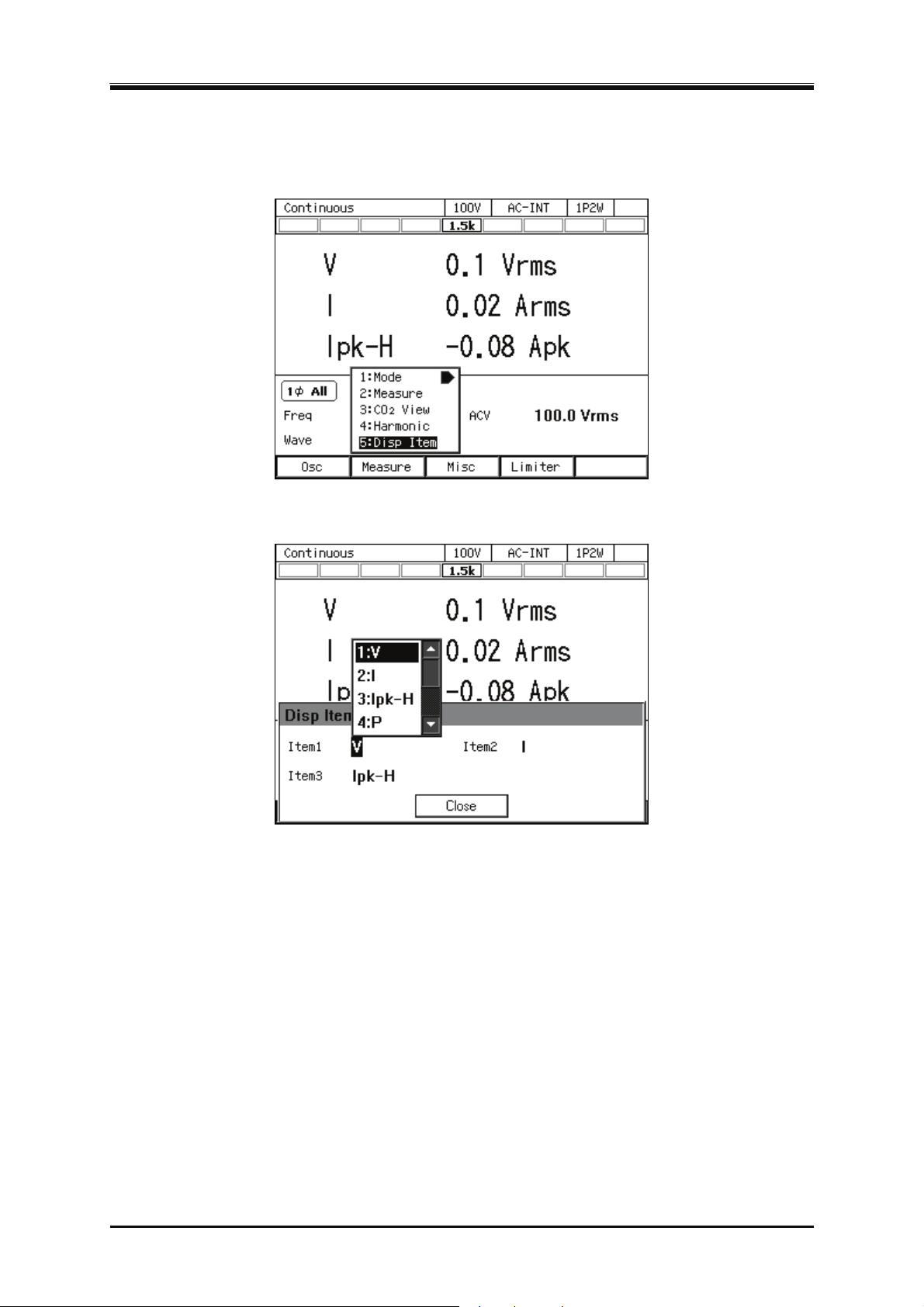
3. Basic Operation
Selecting the measured value being displayed in the Simple View mode (procedure 1)
In the Simple View mode, press the [Measure] soft-key and select [5:Disp Item]. The setting
1.
window for display items opens.
In the [Item1] to [Item3] items, select measured values to be displayed.
2.
62
Close the window. For how to close the window, see
3.
.
3.3.4
PROGRAMMABLE AC POWER SOURCE
Page 81
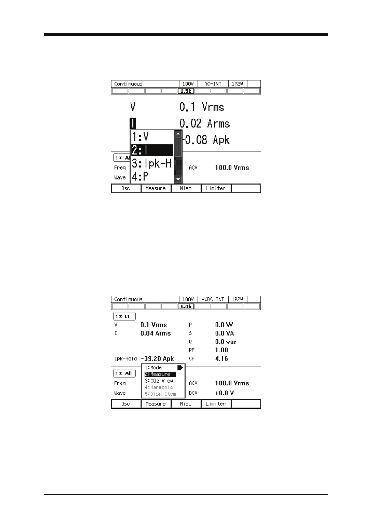
3.4 Using the Continuous Function
Selecting the measured value being displayed in the Simple View mode (procedure 2)
In the Simple View mode, hover the cursor over the measured value item and press the ENTER key.
The selection box for choosing display items opens.
3.4.12 Clearing the Output Current Peak-hold Value
The output current peak-hold value is the maximum absolute value of the measured output current
peak value, which is then updated appending signs and held. This held value can be cleared. After
the held value is cleared, it is updated with the value measured after that. The held value is cleared
when the power is turned off.
Operation procedures using soft-keys
Press the [Measure] soft-key and select [2:Measure]. The [Measure] window opens.
1.
DP Series
63
Page 82
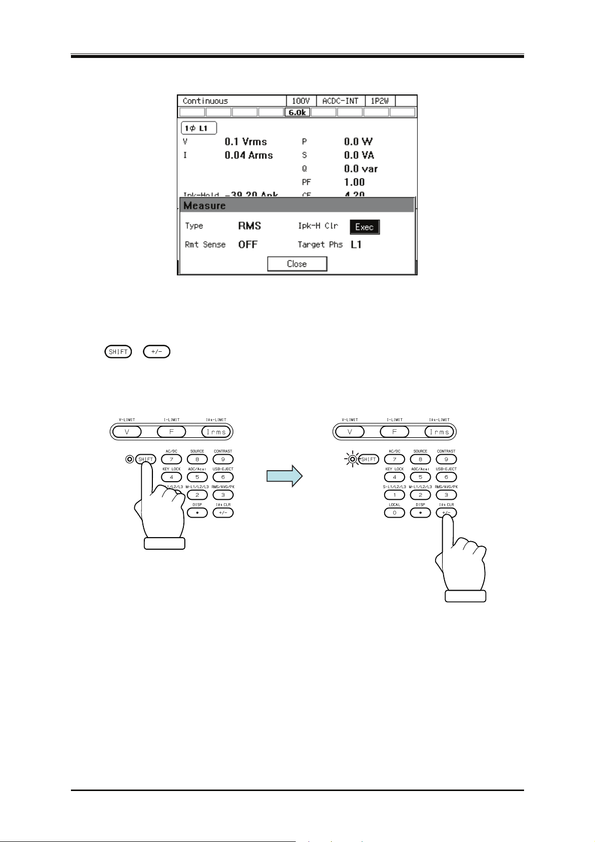
3. Basic Operation
Move the cursor to [Exec] of the [Ipk-H Clr] item and press the ENTER key.
2.
Close the window. For how to close the window, see
3.
peration procedures by using shortcuts
O
1.
+ Clearing the current peak-hold value
Press the SHIFT key to enter the shift state (the SHIFT LED illuminates). When you press the
+/− key in the numeric keypad in the shift state, the output current peak-hold value is cleared.
3.3.4
.
64
PROGRAMMABLE AC POWER SOURCE
Page 83
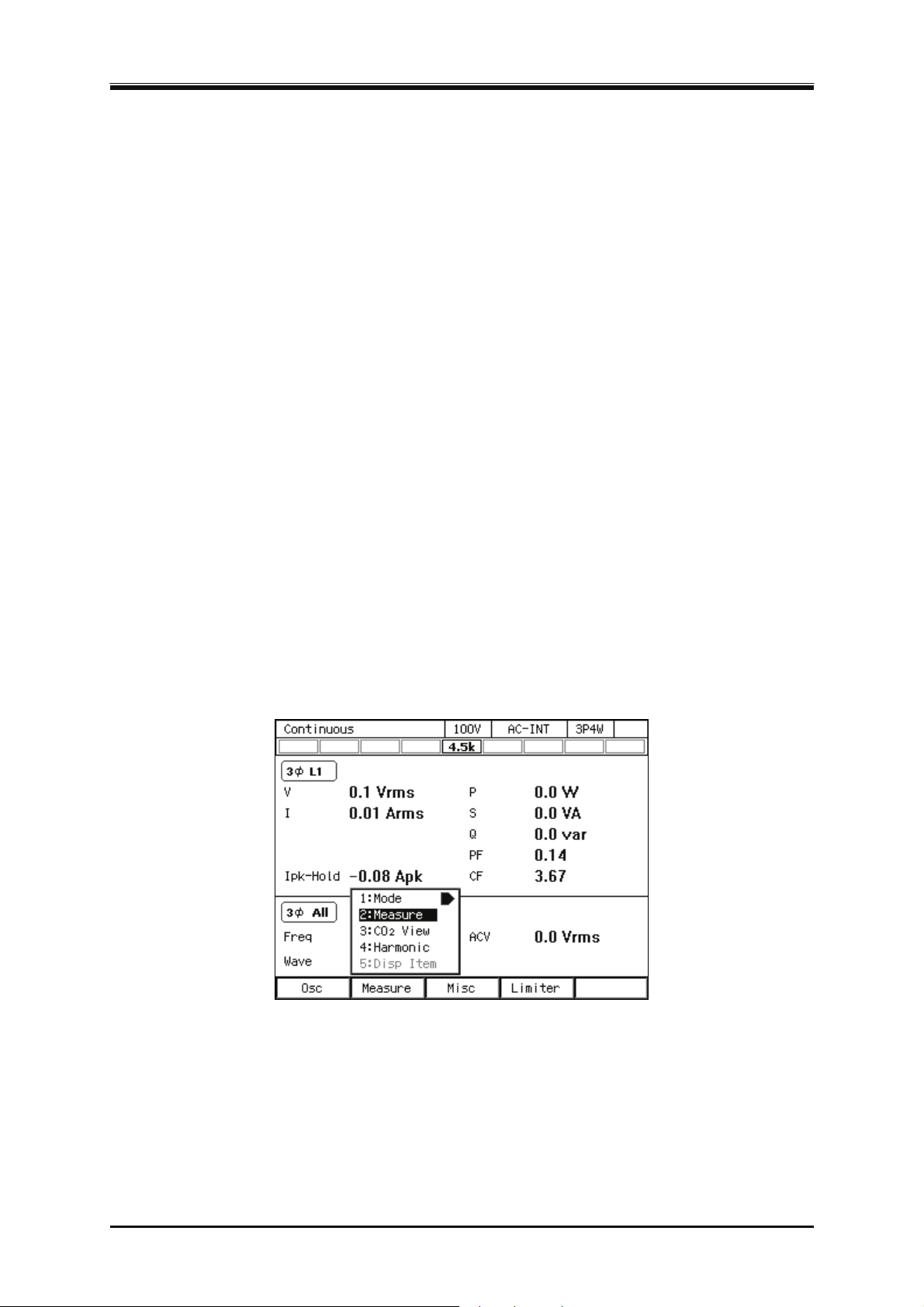
3.4 Using the Continuous Function
3.4.13 Switching the Target Phase of which the Measured Values are Displayed (Polyphase Output)
You can switch the phase of which the measured values is displayed on the LCD screen in the
polyphase model and of L1 cabinet in the polyphase system. You can select the line voltage display.
-------- Notes----------------------------------------------------------------------------------------------------------------
Even if the line voltage display is selected, the phase voltage is displayed when Peak is
selected for the measuring mode. If L1-L2, L2-L3, or L3-L1 is selected, the maximum and
minimum peak values of the phase voltage for L1, L2, or L3 is displayed respectively.
The line voltage display (RMS display) is not the line voltage value that is measured directly.
This is the value that is calculated based on the phase setting value and the measured phase
voltage value.
In the line voltage display, the measured output current value indicates the phase current. If
L1-L2, L2-L3, or L3-L1 is selected, measured values of the phase current for L1, L2, L3 is
displayed.
In the line voltage display, the power factor and crest factor are not displayed.
In the line voltage display, the measured output power value indicates the output power of the
phase when in the phase voltage display, and total output power of all phases when in the line
voltage display.
---------------------------------------------------------------------------------------------------------------------------------
Operation procedures using soft-keys
Press the [Measure] soft-key and select [2:Measure]. The [Measure] window opens.
1.
DP Series
65
Page 84
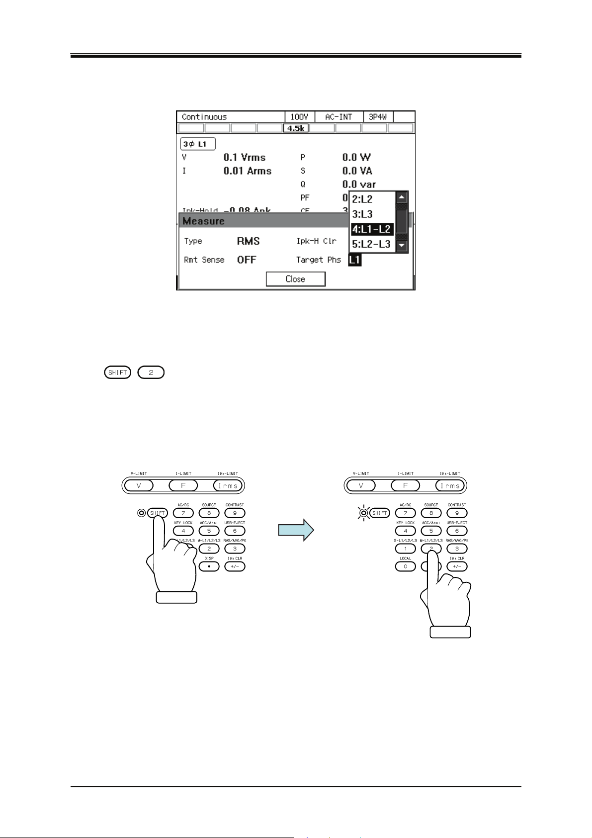
3. Basic Operation
In the [Target Phs] item, select the phase of which the measured value is to be displayed. For
2.
the line voltage, select L1-L2, L2-L3, or L3-L1.
Close the window. For how to close the window, see
3.
O
peration procedures by using shortcuts
1.
+ Switches the target phase of which the measured value is displayed
Press the SHIFT key to enter the shift state (the SHIFT LED illuminates). When you press the 2
key in the numeric keypad in the shift state, the phase is switched in the order of
L1→L2→L1-L2→L1 ... in the single-phase three-wire. In the three-phase, it is switched in the
order of L1→L2→L3→L1-L2→L2-L3→L3-L1→L1 ...
3.3.4
.
66
PROGRAMMABLE AC POWER SOURCE
Page 85

4. Advanced Operation
4.1 Using Limiter, Setting Limiter ···································· 68
4.2 Using Sequence F
unction ········································· 75
4.3 Using Power Fluctuation T
Function ··································································· 103
4.4 Measuring Harmonic Current ·································· 127
4.5 Measuring Inrush Current········································ 129
4.6 Using Clipped S
4.7 Outputting Arbitrary Waveform ································ 134
4.8 Using Memory Function ·········································· 139
4.9 Using USB Memory Function ·································· 153
4.10 Using Monitor Function ··········································· 154
4.11 Using Remote Sensing Function ····························· 157
4.12 Using AGC Function ················································ 160
4.13 Using Autocal Function············································ 163
4.14 Adjusting DC Offset ················································· 167
4.15 Using for Unbalanced P
4.16 Using as DC Power Supply ····································· 171
4.17 Setting Voltage using Ext
4.18 Control Using External Control Function················· 176
4.19 Synchronizing the Output Frequency with the
ine Wave········································ 131
esting (Simulation)
olyphase Output ················ 169
ernal DC Input Signal ······ 172
DP Series
ower Line or the External Signal ··························· 181
P
4.20 Amplifying the External S
4.21 Turning the Output On or Off Rapidly······················ 184
4.22 Enabling Automatic Output-On at Power-On··········· 186
4.23 Using the Emission CO2 Calculator ························ 187
4.24 Power Unit Energization Setting (Using Under the
estricted Rated Power) ········································· 189
R
4.25 Key Lock·································································· 191
4.26 Beep ········································································ 191
4.27 Changing the Background Color and the Contrast
f the Screen ··························································· 192
o
4.28 Restoring to the Factory Default Setting (Reset) ···· 193
ignal Input (Optional) ······ 183
67
Page 86

4. Advanced Operation
4.1 Using Limiter, Setting Limiter
4.1.1 Use Peak Current Limiter
Peak value of output current is limited by the peak current limiter. While the limiter is working, icon
is displayed and LIMIT LED illuminates.
Setting values of peak current limiter are variable, and kept independently for each of 100 V and 200
V ranges.
You can choose whether to make the output off or not upon the triggering of the peak current limiter.
If you choose to set the output off, specify the continuous operation time of limiter until the output
off becomes effective. Whether output off is set or not and the time setting are common regardless
of the output ranges.
For the default setting range, see 10.13.
-------- Not
Output current value may be limited by a value that is different from the setting value,
For an inductive load, overvoltage protection may be triggered due to the operation of peak
When the number of power units that are energized is increased or decreased based on the
In the polyphase model and the polyphase system, the setting of the peak current limiter is
If the output off after the continuous operation of the limiter for the specified duration is
In the case that the peak current limiter operates when the setting value of the peak current
---------------------------------------------------------------------------------------------------------------------------------
Operation procedure
1.
es----------------------------------------------------------------------------------------------------------------
depending on the load.
current limiter. Overvoltage protection may be avoided by lowering the limiter setting value
both for negative and positive values.
power unit energization setting, the setting values of the peak current limiter are reset to the
factory default setting corresponding to the ratings output power (e.g. reset to the factory
default setting of 4.5 kVA model when only three units of 6 kVA model are in operation).
common to all phases.
enabled, the setting of output-off phase is ignored.
limiter is set as asymmetry between positive and negative in the AC mode, the DC component
is generated in the output. Although the function to remove the DC component of the output
works in the AC mode, when the peak current limiter operates intermittently, the DC
component may not be removed sufficiently, or the output waveform may be modified.
Push [Limiter] soft-key to select 1: Ipk Limiter (or push
current limiter set window.
+ ). Opens the peak
68
PROGRAMMABLE AC POWER SOURCE
Page 87
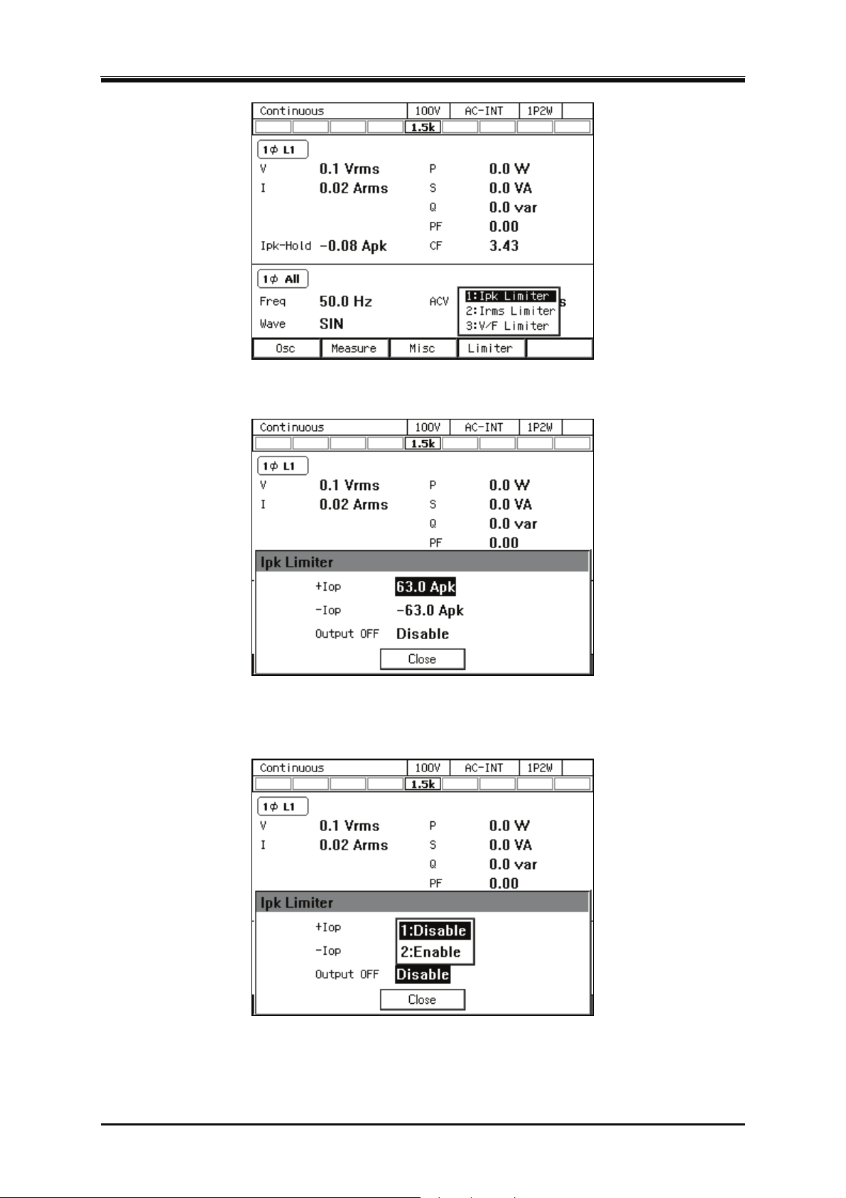
4.1 Using Limiter, Setting Limiter
In the [+Iop]/[−Iop] item, set the peak current limiter value of positive/negative.
2.
Set the [Output OFF] item as [Enable] or [Disable]. When setting to [Enable], also set the time
3.
from the start of limiter operation to the output off.
Close the window.
4.
DP Series
69
Page 88
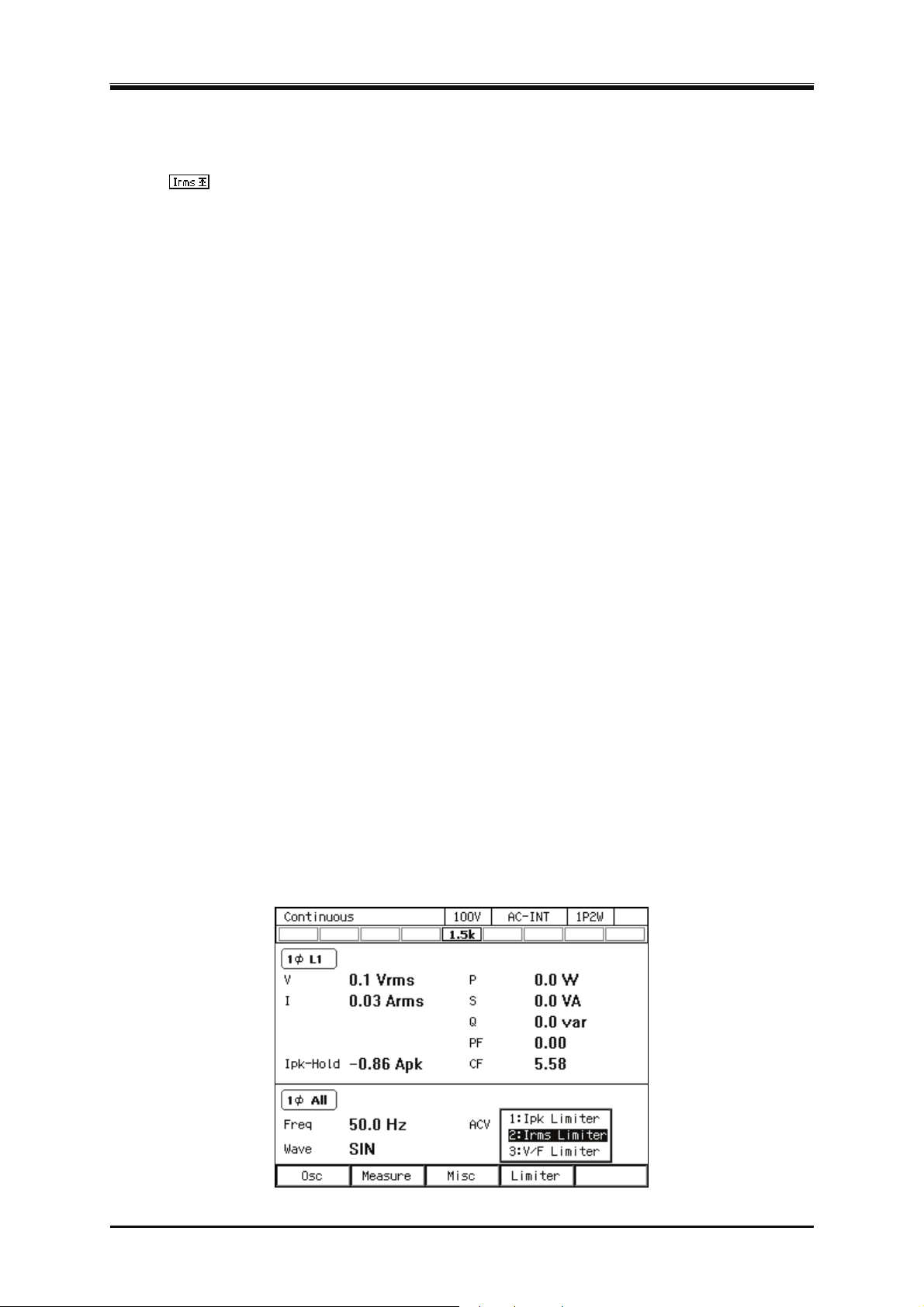
4. Advanced Operation
4.1.2 Using RMS Current Limiter
Effective value of output current is limited by the RMS current limiter. While the limiter is working,
icon
Setting values of RMS current limiter are variable, and kept independently for each of 100 V and
200 V ranges.
You can choose whether to make the output off or not upon the triggering of the RMS current
limiter. If you choose to set the output off, specify the continuous operation time of limiter until the
output off becomes effective. Whether output off is set or not and the time setting are common
regardless of the output ranges.
For the default setting range, see 10.13.
-------- Not
It will take time from the limiter starts operation until the output current is restricted enough,
because the RMS current limiter needs to calculate effective value. Use the peak current
limiter to limit the current quickly. For peak current limiter, see 4.1.1.
R
is very small (e.g. output short circuit). Also, RMS current protection may work in this case
and then output is turned off.
When the number of units is increased or decreased based on the power unit energization
setting, the setting is reset to the factory default setting corresponding to the capacity (e.g.
reset to the factory default setting of 4.5 kVA model when only three units of 6 kVA model are
in operation).
In the polyphase model and the polyphase system, the setting of the RMS current limiter is
common to all phases.
If the output off after the continuous operation of the limiter for the specified duration is
enabled, the setting of output-off phase is ignored.
---------------------------------------------------------------------------------------------------------------------------------
Operation procedure
1.
is displayed and LIMIT LED illuminates.
es----------------------------------------------------------------------------------------------------------------
MS current limiter may not be able to limit output current sufficiently if the load impedance
Push [Limiter] soft-key to select 2:Irms Limiter (or push I key). Opens the RMS current limiter
set window.
70
PROGRAMMABLE AC POWER SOURCE
Page 89
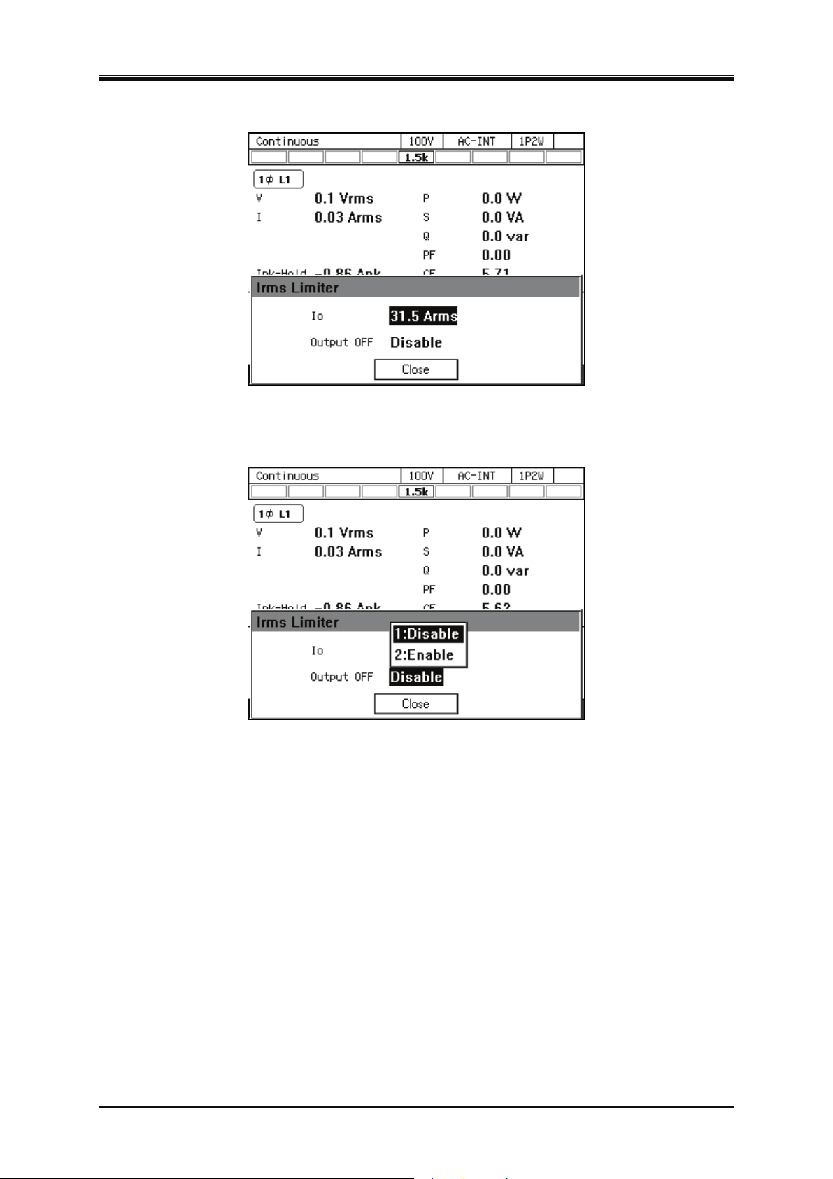
4.1 Using Limiter, Setting Limiter
Set the value of RMS current limiter in [Io] item.
2.
Set the [Output OFF] item as [Enable] or [Disable]. When setting to [Enable], also set the time
3.
from the start of limiter operation to the output off.
Close the window.
4.
4.1.3 Using Voltage Setting Range Limit
For the continuous output function, when the signal source is INT, SYNC, or ADD, the range of the
output voltage setting value to the internal signal source can be limited. Even if trying to set a
voltage that exceeds the limit, the setting value is restricted to the limiting value. This can prevent
mis-setting when you do not want to set values outside the range.
As for the voltage setting range limiting values, each value is kept independently for the following
settings for 100 V and 200 V ranges respectively: SIN/CLP waveform in AC mode, ARB waveform
in AC mode, ACDC mode, and DC mode.
In case of polyphase output, the setting of the voltage setting range limit is common to all phases,
and kept as the effective value of the phase voltage in this product. When the line voltage setting
(effective value setting) is selected in balanced mode, it is converted into the effective value setting
of the phase voltage according to the following formula and kept in this product.
DP Series
71
Page 90
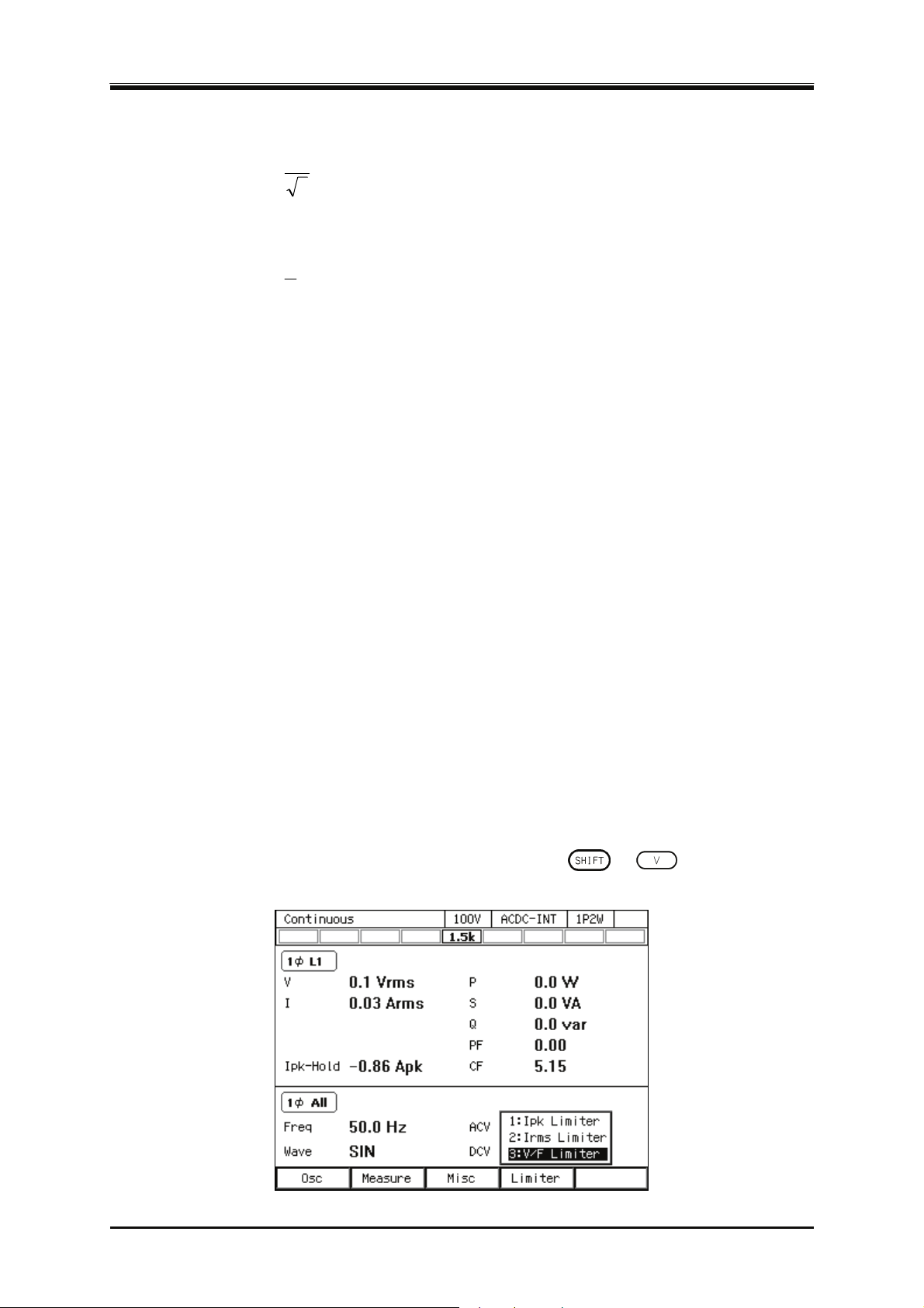
4. Advanced Operation
Balanced three-phase output:
voltagePhase ×=
1
voltageLine
3
Balanced single-phase three-wire output:
voltagePhase ×=
1
voltageLine
2
The limiting value should be set using the effective value or the positive and negative peak value.
The effective value can be used only when in the AC mode and the waveform is a sine wave or a
clipped sine wave. The limiting value can be set using the line voltage in polyphase output when in
AC mode and balanced mode, and the output voltage setting is a line voltage setting. In other cases,
set using the positive and negative peak values of phase voltage.
For the default setting range, see 10.14.
-------- Not
The voltage setting range limit is useful for the prevention of an excessive output when a
The limitation is applied to the additional values of the AC voltage setting (recalculated to a
The voltage setting range limit cannot be applied to the external signal source of EXT and ADD.
The Sequence and the Simulation function do not include the voltage setting range limiting
The voltage setting range limit that does not include an output voltage already set cannot be set.
In polyphase output, the voltage setting range limit is common to all phases.
In ACDC mode, set the voltage setting range limit setting using the positive and negative peak
---------------------------------------------------------------------------------------------------------------------------------
Operation procedure
1.
es----------------------------------------------------------------------------------------------------------------
setting value is rapidly increased or decreased by using the shuttle.
peak value) and the DC voltage setting.
function.
values of the phase voltage regardless of the settings of the waveform, balanced/unbalanced
mode, phase voltage/line voltage.
Push [Limiter] soft-key to select 3: V/F Limiter (or push
window for the voltage/frequency setting range limit.
+ ). Opens the setting
72
PROGRAMMABLE AC POWER SOURCE
Page 91
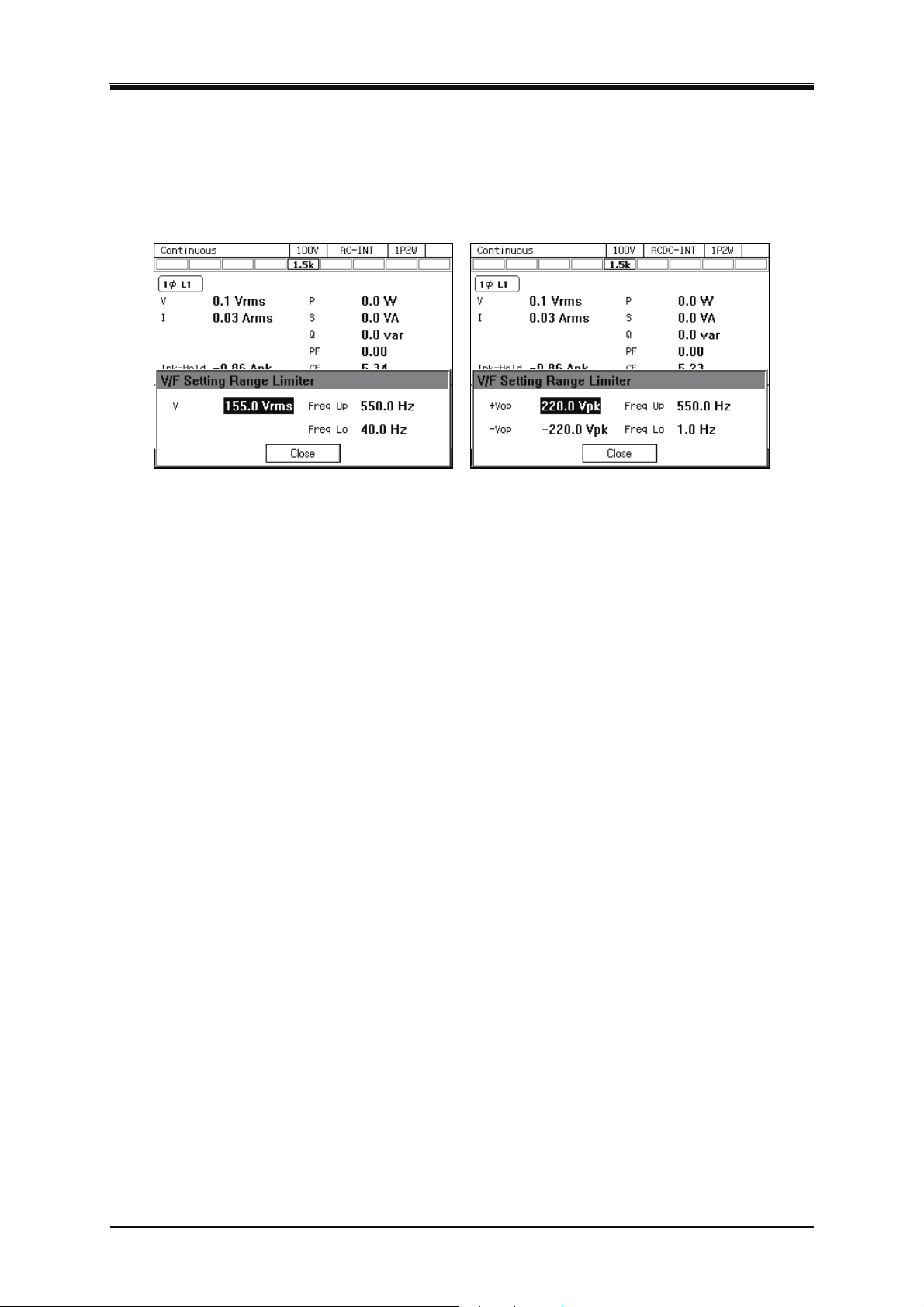
The screen for the effective value setting or the peak value setting opens depending on the
2.
signal source setting/output waveform settings made here. Set the voltage setting range limiting
value in the [V] item (effective value setting) and [+Vop]/[−Vop] item (peak value setting).
Effective Value Setting Peak value setting
Close the window.
3.
4.1.4 Using Frequency Setting Range Limit
4.1 Using Limiter, Setting Limiter
You can limit the range of the frequency setting value for the internal signal source by using the
frequency setting range limit. Even if trying to set a frequency that exceeds the limit, the setting
value is restricted to the limiting value. This can prevent mis-setting when you do not want to set
values outside the range.
The frequency setting range limiting value is common to both 100 V and 200 V ranges.
For the default setting range, see 10.14.
-------- Not
es----------------------------------------------------------------------------------------------------------------
The frequency setting range limit is useful for the prevention of an unintended frequency
setting when a setting value is rapidly increased or decreased by using the shuttle.
---------------------------------------------------------------------------------------------------------------------------------
DP Series
73
Page 92
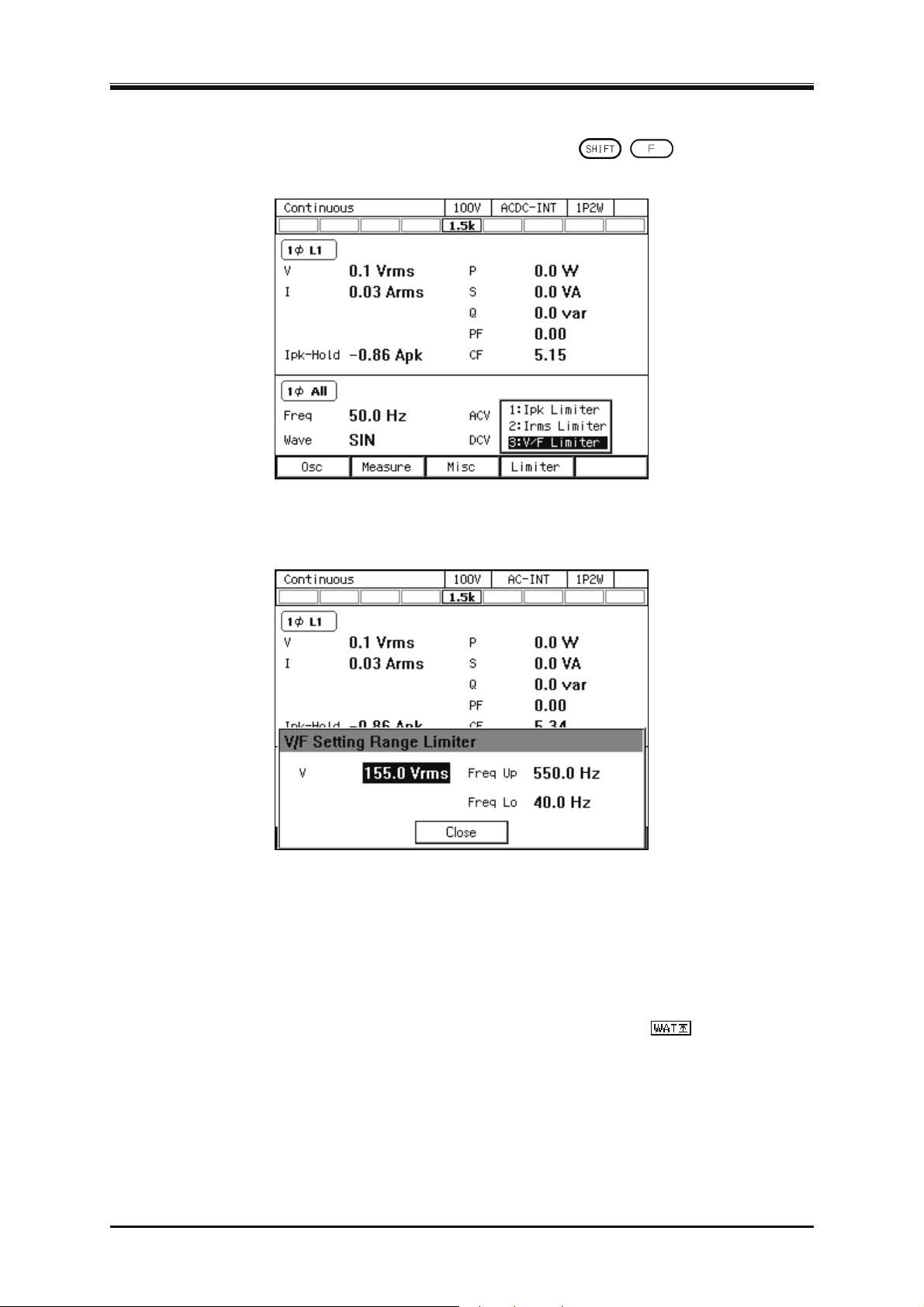
4. Advanced Operation
Operation procedure
Push [Limiter] soft-key to select 3: V/F Limiter (or push
1.
window for the voltage/frequency setting range limit.
Set values in the [Freq Up]/[Freq Lo] item so that the upper value of the frequency setting range
2.
limit is higher than or equal to the lower limit.
+ ). Opens the setting
Close the window.
3.
4.1.5 About Wattage Limiter
The wattage limiter operates when trying to output the power exceeding the rated power. When the
wattage limiter operates, the output voltage is suppressed until the active power per phase is the
value in Table 4-1 (reference value). While the limiter is working, icon
LIMIT LED illuminates.
74
PROGRAMMABLE AC POWER SOURCE
is displayed and
Page 93
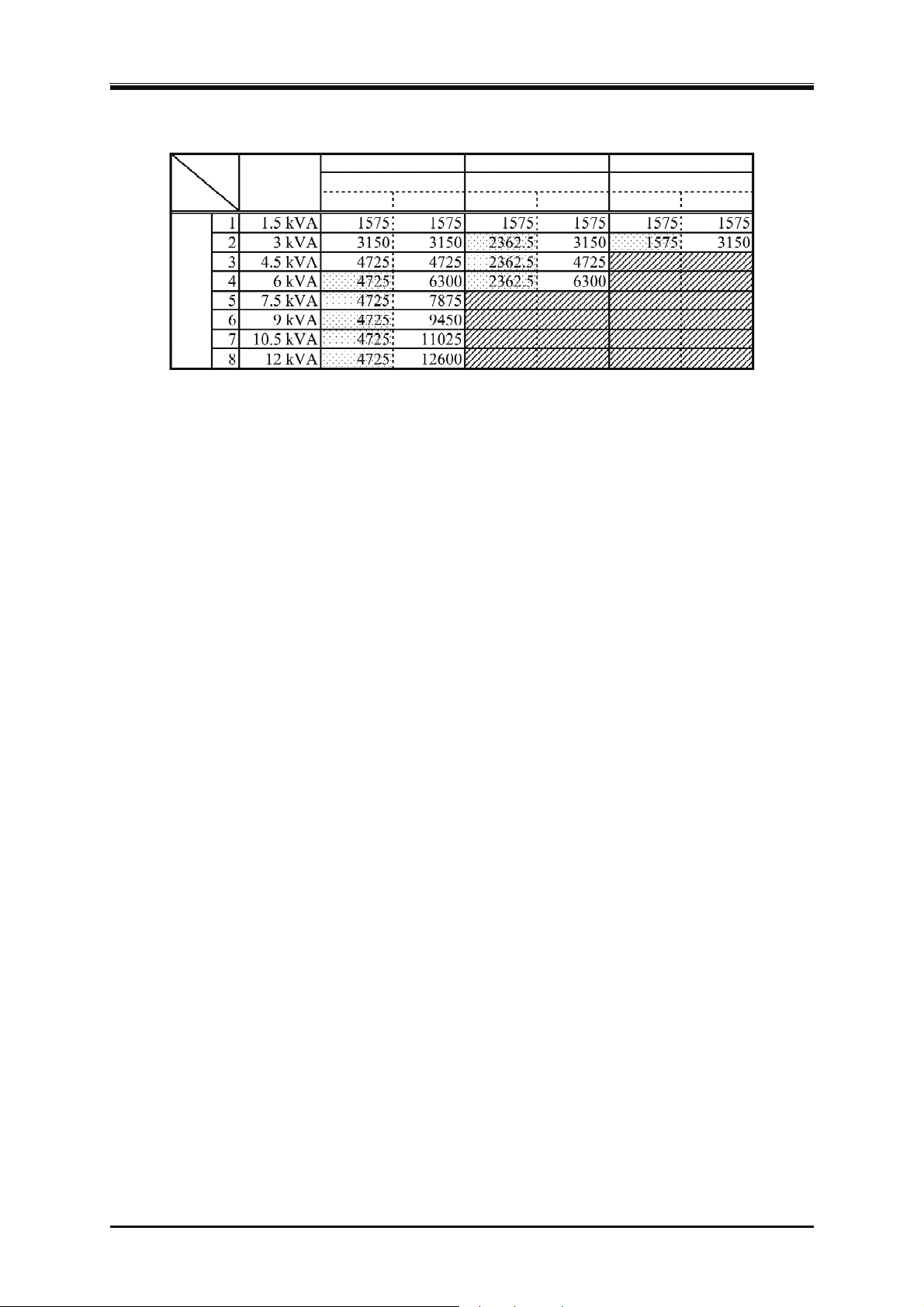
4.2 Using Sequence Function
Table 4-1 Wattage Limiter Value per Phase (Reference value, Unit: W)
Number of power units
Rated output
per phase
per phase
Single-phase model
Power Input
100 V system 200 V system 100 V system 200 V system 100 V system 200 V system
Single-phase three-wire model
Power Input
Three-phase model
Power Input
Note: Power input 100 V system is for power input voltage 170 V or less.
-------- Notes----------------------------------------------------------------------------------------------------------------
If the wattage limiter operates, suppress the output wattage within the rated output power by
lowering the output voltage setting value.
Active power (unit: W) is restricted by the wattage limiter, however, reactive power (unit: var)
is not restricted. Therefore, the apparent power (unit: VA) may exceed the rated power
depending on the power factor of the load. Set the output voltage so that the apparent power
does not exceed the rated power, regardless of the operation of the wattage limiter.
The value of the wattage limiter cannot be changed. To limit the output power to a value that is
lower than the rating, decrease the number of power units that are energized through the power
unit energization setting, or use the peak current limiter or the RMS current limiter.
When the power input voltage is 170 V or less, the maximum output active power of a model
with the rated power of 6 kVA or higher is limited to 4.725 kW of maximum output active
power by the wattage limiter. However, for a single-phase three-wire model and a three-phase
model, the maximum output active power per phase is limited to 4.725 kW/2 and 4.725 kW/3.
---------------------------------------------------------------------------------------------------------------------------------
4.2 Using Sequence Function
4.2.1 Basics
By using Sequence function (optional), an output setting can be changed step-by-step according to
the program (sequence) created beforehand. This section describes the basics for using the Sequence
function.
AC/DC Mode and Signal Source
Sequence function keeps the selection of the AC/DC mode and a signal source, independently from
continuous output function/Simulation function. AC/DC mode can be selected from AC/ACDC/DC.
A signal source is fixed as INT.
DP Series
75
Page 94
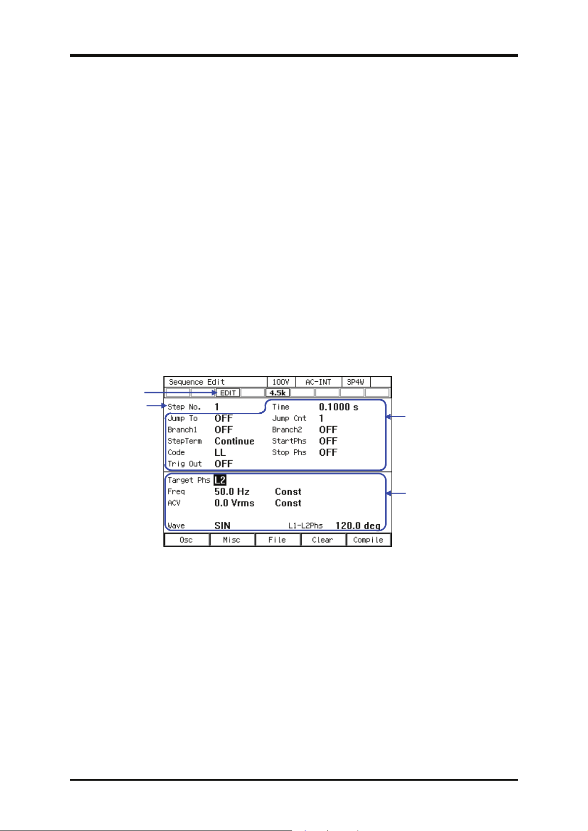
4. Advanced Operation
Keep a sequence setting
The sequence setting is kept per AC/DC mode. Every time AC/DC mode is changed, the sequence
setting that is already kept is loaded. The sequence setting is cleared when the power is turned off.
To save the setting, you need to save it in internal memory or USB memory (see 4.9).
St
ep
One sequence consists of a series of two or more steps. To use Sequence function, first set each step.
Step-control Parameters and intra-Step Parameters
There are the following two major types of parameters in Sequence function:
Step-control parameter
Parameter to control the flow between two or more steps. This defines duration of each step
and the next step to transition. Settings of step synchronous code and trigger output are
included in step-control parameter for convenience.
Intra-Step parameter
Parameter to define output state in each step. This defines basic parameters such as a
waveform, frequency, and how they are changed in the step.
アイコン
Icon
Step number
ステップ番号
Step-control parameter
ステップ制御パラメタ
ステップ内パラメタ
Intra-Step parameter
Figure 4-1 Step-control Parameters and intra-Step Parameters
Step No. 0
Step No. 0 is assigned to the stand-by state before the sequence starts. If the terminal specification
of the step other than No. 0 is End, the execution transitions to step No. 0 and enters into the
stand-by state. Step Time and the Step Behavior setting of No. 0 specifies the action to transit to No.
0 at the end of a sequence.
76
PROGRAMMABLE AC POWER SOURCE
Page 95
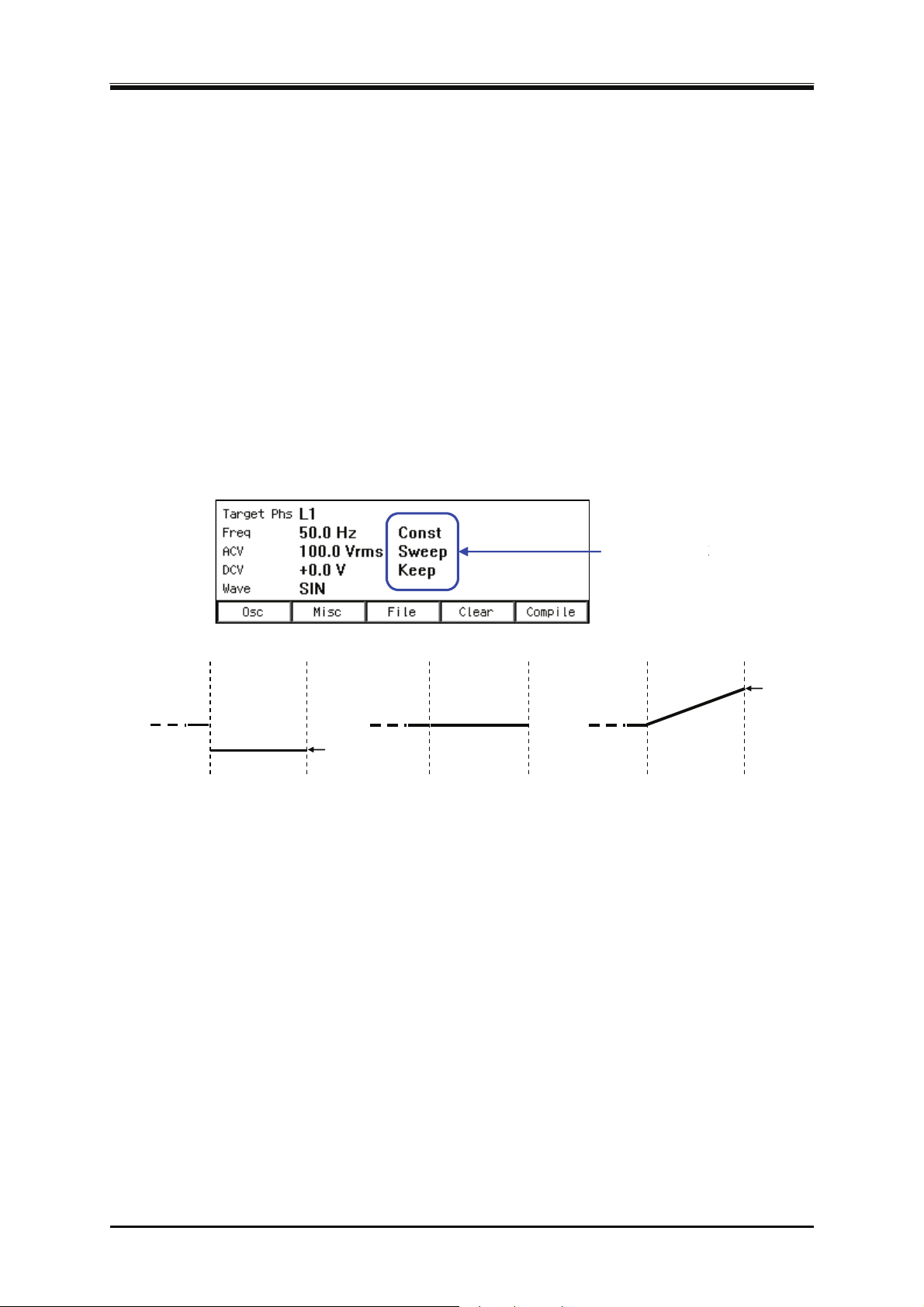
4.2 Using Sequence Function
種
f
Step Behavior (Const, Keep, Sweep)
For the intra-Step parameter other than waveforms and phases, the following three patterns can be
set as the method to change values in the step.
Constant (Const)
Fixed to the value set in the step.
Keep (Keep)
Keeping the value immediately before transitioning to the step. That is, the value is changed
depending on the status of the previous step. Although the parameter value can be set even if
the operation type setting is Keep, the parameter setting value is ignored when sequence is
executed.
Sweep
It changes linearly from the value immediately before transitioning to the value set in the step,
taking the Step Times. In other words, it reaches the setting value after the Step Time passes in
the step. The starting value is changed depending on the status of the previous step.
Step Behavior
ステップ動作
Previous step
Next step
Used as the setting
value in the next step
Const
Previous step Next step Previous step Next step
Setting
value
Keep
Keeps the final value
of the previous step
Changes from the final value o
the previous step to the setting
value of the next step
Sweep
Setting
value
Figure 4-2 Step Behavior
-------- Notes----------------------------------------------------------------------------------------------------------------
The Step Behavior for the waveform and phase is always Constant (Const).
Keeps as many intra-Step parameter setting values as the number of phases in each step based
on the output phase mode.
Cannot be set using line voltage in the single-phase three-wire output and three-phase output.
The rate of crest factor/clip ratio cannot be changed though a clipped sine wave can be selected
as an output waveform in Sequence function. Set these parameters beforehand using
continuous output function.
Sequence function displays the measured value in Sequence function, which is equivalent to
that of the continuous output function. However, harmonic current measurement (see 4.4)
cannot
be displayed.
---------------------------------------------------------------------------------------------------------------------------------
DP Series
77
Page 96
4. Advanced Operation
4.2.2 Parameters of Sequence Function
Table 4-2 shows the parameters of Sequence function. The common parameters are common to one
sequence. In Sequence function, signal source is fixed to INT. In each step, set the step-control
parameter and the intra-Step parameter. As for intra-Step parameter, the item and range that can be
set differ depending on the output range (100 V/200 V range) and output mode
(AC-INT/ACDC-INT/DC-INT) as in the case of continuous output function. This section describes
intra-Step parameters and step-control parameters separately.
Table 4-2 Parameters of Sequence Function
Common
parameter
Output range
AC/DC mode
Frequency (Freq), waveform (Wave), phase angle (Phase), AC phase voltage (ACV), DC
voltage (DCV)
The setting for the output of each step. In polyphase model/polyphase system, AC phase voltage and
phase angle can be set for each phase. In the phase angle, set the phase difference with the L1 phase.
Phase angle can also be set per step. The phase angle of L1 phase cannot be set, and is fixed as 0
deg.
Step Time (Step Time)
Set the output time of that step. Unit can be selected from [s] or [ms].
Jump-to step (Jump To)
When selected, the destination step of the jump at the end of the step can be specified. By specifying
the Jump count ([Jump Cnt]), you can set up a loop to repeat the same step. After jumping for the
times specified for one sequence, the action at the end of step follows the step termination setting.
If Jump-to is set to off, the action at the end of step follows the step termination setting.
-------- Notes----------------------------------------------------------------------------------------------------------------
When the step termination is set as [Hold], the hold status is enabled before the jump.
---------------------------------------------------------------------------------------------------------------------------------
Step Time
Specification of the Jump-to step
Jump count (1 to 9999, or infinite)
Specification of the branch step
Start phase
Stop Phase
Step termination
Synchronous step output (2bit)
Trigger output
Step-control parameter Intra-Step parameter
Frequency
Waveform
Phase angle
AC phase voltage
DC voltage
78
PROGRAMMABLE AC POWER SOURCE
Page 97

4.2 Using Sequence Function
Jump count (Jump Cnt)
Number of times of jumps to jump to the step specified in Jump-to. This can be set when Jump-to
([Jump To]) is selected. When the Jump count is set to 0, infinite times of jumps occur.
-------- Notes----------------------------------------------------------------------------------------------------------------
The number of times that a particular step is repeated is Jump count +1.
---------------------------------------------------------------------------------------------------------------------------------
Branch step (Branch1, Branch2)
When the step is under execution or in the hold state, the step to transition when the branching
instruction through panel operation or external control is detected can be specified. There are two
systems of branch instructions (Branch1 and Branch2), and an instruction can be set for each.
-------- Notes----------------------------------------------------------------------------------------------------------------
Transition using branch is executed immediately after a branching instruction is detected. Step
Time, Stop Phase, and step termination setting are ignored.
---------------------------------------------------------------------------------------------------------------------------------
Step termination (Step Term)
Specifies the action when the step completes. When [Continue] is selected, transitions to the step of
the next number. When [End] is selected, the sequence is terminated and the execution transitions to
step No. 0 and enter into the stand-by state. When [Hold] is selected, the output at the end of the step
is suspended, and the execution transitions to the step of the next number when Resume instruction
is detected.
-------- Notes----------------------------------------------------------------------------------------------------------------
When [Step Term] is set to [Hold], the execution enters into hold state before jump. Jumps
when Resume instruction is detected.
When [Step Term] is set to [Hold], after the jumps repeated for the specified Jump count, the
execution transitions to the step of the next number when Resume instruction is detected in
hold state.
While in the hold state due to the step termination in a step where step termination phase is
enabled, the execution transitions to Jump-to step or the step of next number when Resume
instruction is detected, after the hold state is kept until Stop Phase.
---------------------------------------------------------------------------------------------------------------------------------
Step sync code output (Code)
State output to CONTROL I/O connector. Code to output while the execution of the step, which is
specified by 2-bit H/L.
Start Phase (StartPhs)
Determines the phase of AC waveform of L1 phase when the step starts. The phase when a step
starts in L2 and L3 phase of polyphase model/polyphase system is the addition of the setting value
of intra-Step parameter Phase and the setting value of the step Start Phase.
DP Series
79
Page 98
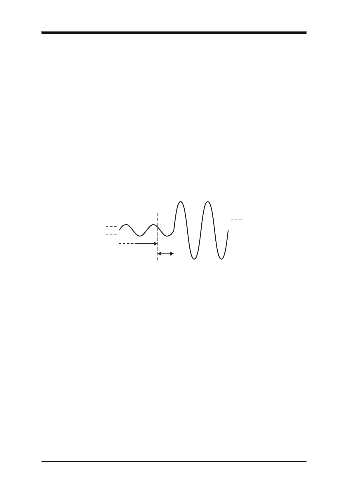
4. Advanced Operation
-------- Notes----------------------------------------------------------------------------------------------------------------
Step Start Phase setting can be disabled. In that case, the phase when the phase starts becomes
the phase when the previous step ended.
In DC mode, the step Start Phase cannot be set.
---------------------------------------------------------------------------------------------------------------------------------
Stop Phase (Stop Phs)
Determines the phase of AC waveform when the step ends. The phase when a step ends in L2 and L3
phase of polyphase model/polyphase system is the addition of the setting value of intra-Step
parameter Phase and the setting value of the step Stop Phase. When the stop phase setting is active,
the execution waits for the Step Time that was set pass, and keeps the output setting until it reaches
the Stop Phase that was set, and then transitions to the next step. As the result, the actual step time is
longer by one cycle at a maximum than the set Step Time. Figure 4–3 shows an example where both
the S
top Phase of the previous step and the Start Phase of the next step are set to 0°.
Step Time finished
Waiting for stop phase
Next step Previous step
Figure 4-3 Stop Phase
-------- Notes----------------------------------------------------------------------------------------------------------------
When the Step Behavior is set to [Sweep], output is constant while waiting for the step Stop
Phase after the Step Time passes.
Step Stop Phase setting can be disabled. In this case, when the set Step Time has passed, the
execution transitions to the next step without waiting for step Stop Phase.
In DC mode, the step Stop Phase cannot be set.
---------------------------------------------------------------------------------------------------------------------------------
Trigger output (Trig Out)
State output to CONTROL I/O connector. This specifies whether the trigger output presents when
the step starts. Polarity and pulse width of the trigger output complies to the trigger output setting
(see 4.2.5).
80
PROGRAMMABLE AC POWER SOURCE
Page 99
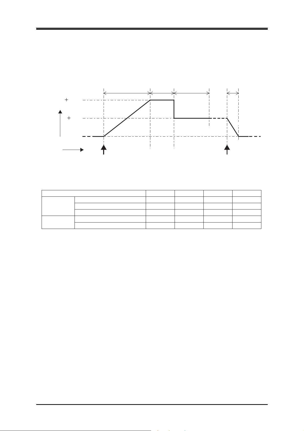
4.2 Using Sequence Function
4.2.3 Example of Output Using Sequence Function
As an example, consider the sequence that gradually changes DC voltage like Figure 4–4.
Set the output mode to DC-INT. Edit the sequence like Table 4-3. Parameters not included in this
t
able should be left as the factory default setting.
100V
50V
Time
0V
Step0
Start
Start operation Stop operation
Output voltage
20s 10s 15s 5s
Keep
Sweep
Step1 Step2 Step3 Step0
Const
Hold
Stop
Sweep
Figure 4-4 Example of Sequence
Table 4-3 Example of Editing Sequence
Step Number 0 1 2 3
Step-control
parameter
Step Time (Time) 5 s 20 s 10 s 15 s
Jump-to (Jump To) — OFF OFF OFF
Step termination (Step Term) — Continue Continue Hold
DC Voltage (DCV) 0 V +100 V (Optional) +50 V Intra-Step
Parameter
Step Behavior Sweep Sweep Keep Const
-------- Notes----------------------------------------------------------------------------------------------------------------
Step Time and the Step Behavior of step No. 0 specifies the action after the transition to step
No. 0 at the end of a sequence.
Jump-to of step No. 0 cannot be specified. The execution always transitions to step No. 1 when
the sequence starts.
In the case that the step termination is set to [Hold] (No. 3), and when the execution is in the
Hold state, it transitions to step No. 0 and enters into the stand-by state if the Stop operation is
executed. If you perform Resume operation here, the execution transitions to the step of the
next number (No. 4).
---------------------------------------------------------------------------------------------------------------------------------
4.2.4 Process Flow in a Step
Figure 4–5 shows the process flow in one step. The transition such as Figure 4–6 occurs by branch
operation or stop operation, regardless of the flow in the step.
DP Series
81
Page 100
4. Advanced Operation
b
During the specified Step Time, output is performed according to
指定のステップ時間の間,ステップ動作種別設定に従い出力
the Step Behavior setting. When If Hold operation is executed on
します。途中でホールド操作が行われたら,リジューム操作
the way, output state is kept until Resume operation is executed.
が行われるまで出力状態を保持します。
When step termination setting is Hold, output state is kept until
ステップ終端設定がホールドなら,リジューム操作が行われ
Resume operation is executed.
るまで出力状態を保持します。
If stop phase setting is on, the output state is kept until the step
ステップ終了位相設定がオンなら,設定された終了位相に達
reaches the specified Stop Phase.
するまで出力状態を保持します。
If Jump-to setting is on, transitions to the specified step for the
ジャンプ先設定がオンなら,指定のステップへ指定回数だけ
specified times.
移行します。
開始
Start
ジャンプ先の
Transitions to the
ステップへ移行
Jump-to step
When not transition to the Jump-to step
ジャンプ先へ移行しないとき
Transitions to the step of the next number or step No. 0, based on
ステップ終端設定に従い,次番号ステップ又はステップNo. 0
the step termination setting.
へ移行します。
(Continue,Hold)
次番号ステップへ移行
Transitions to the step of
the next number
Transitions to step No. 0
(End)
ステップNo. 0へ移行
=シーケンス終了
=End of sequence
Figure 4-5 Process Flow in Sequence Step
When branch setting is on, the execution transitions to the
specified step according to the branch operation or the signal.
When sequence stop operation is executed, the execution
transitions to step No. 0.
Figure 4-6 Branch Operation/Stop Operation
Transitions to the
ranch step
Transitions to step No. 0
=End of sequence
82
PROGRAMMABLE AC POWER SOURCE
 Loading...