

Page 1
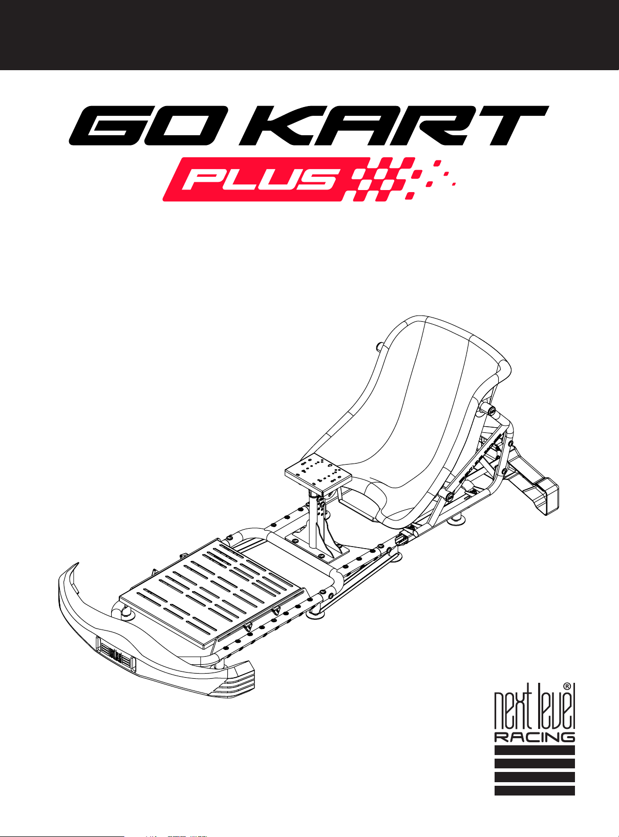
TAKE RACING TO THE NEXT LEVEL
Video Instruction: bit.ly/nlrbuild
INSTRUCTION MANUAL
Page 2
support@nextlevelracing.com
US
YOUR
SIM RACING
JOURNEY
STARTS
HERE
We know you’re eager to start racing! Take your time with the
instructions and follow this guide to assemble your product.
You’ll be setting yourself up for success by following the
instruction booklet to fully optimize your product.
ASSEMBLY
VIDEO
bit.ly/nlrbuild
@next_level_racing
@nextlevelracingOcial
@nextlvlracing
Next Level Racing
FOLLOW
2
Page 3

Video Instruction: bit.ly/nlrbuild
TAKE RACING
TO THE NEXT LEVEL
NEXTLEVELRACING.COM
3
Page 4
PRE-RACE
CHECKS
WARNING & ASSEMBLY TIPS
• Please do not use power tools for assembly as over tightening can damage your frame.
• Do not force parts together.
• Avoid cross threading threaded items.
• If in doubt consult the installation video (see QR code below or contact us at [email protected])
• Hand wash Seat Cover separately in cold water only.
If you require any support with
your product please contact our friendly team at:
WARNING
CHOKING HAZARD - Small parts not for children under 3 years
or any individuals who have a tendency to place inedible objects
in their mouths.
ASSEMBLY
VIDEO
bit.ly/nlrbuild
4
Page 5
IN THE
*NOT TO SCALE
BOX
NOTE: Some Items Come with Rust Resistant Coating
Video Instruction: bit.ly/nlrbuild
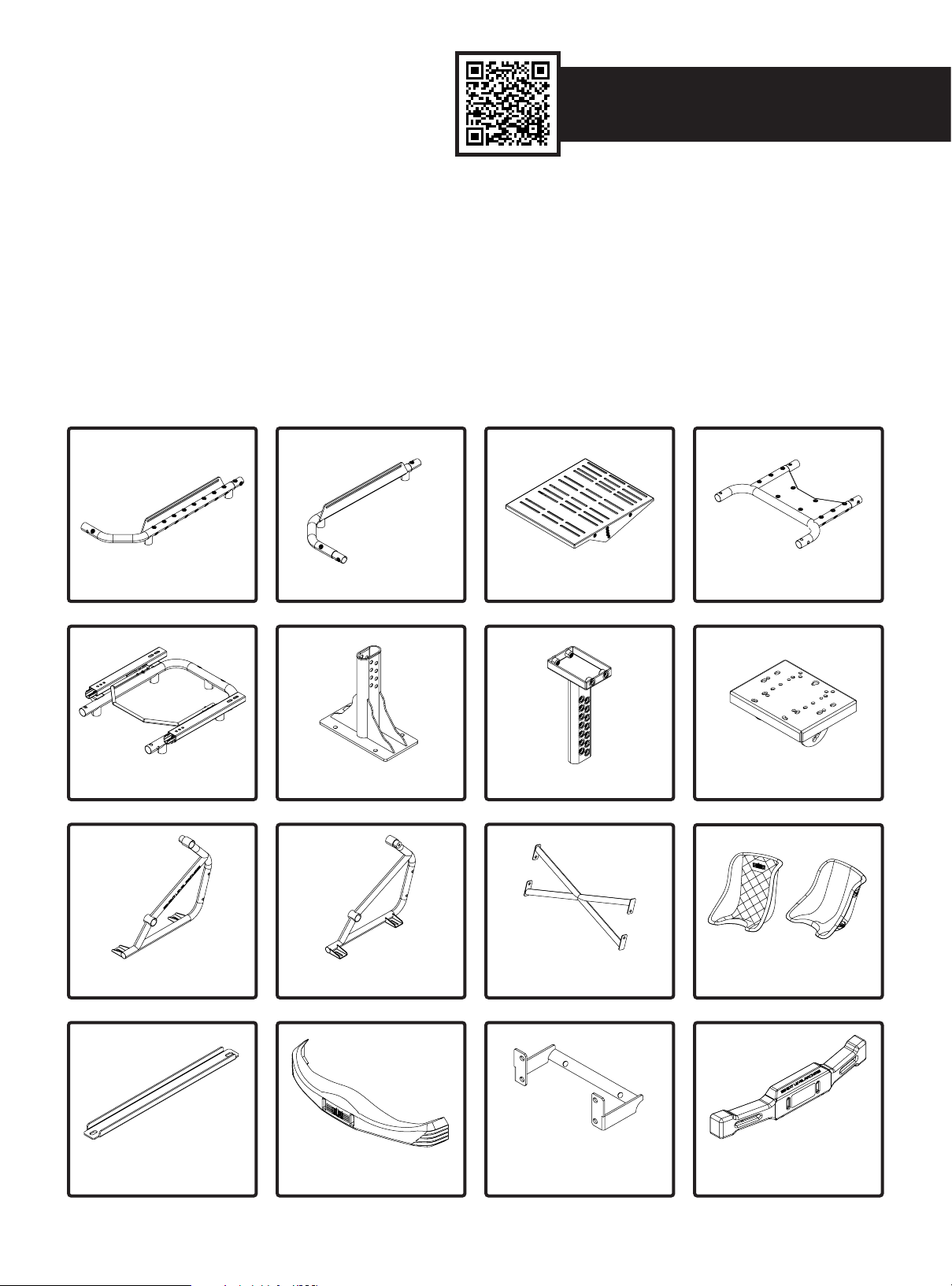
1 x LEFT PEDAL FRAME
1 x LEFT SEAT FRAME
1 x RIGHT PEDAL FRAME
1 x CENTRE POLE BASE1 x REAR FRAME
1 x RIGHT SEAT FRAME
1 x PEDAL PLATE
1 x CENTRE POLE
1 x SEAT CROSS BRACE
1 x CENTRE FRAME
1 x WHEEL PLATE
1 x GO KART SEAT
1 X SEAT COVER
2 x FRAME BRACE
1 x FRONT BUMPER
1 x FRONT BUMPER MOUNT
5
1 x REAR BUMPER
Page 6

1 x REAR BUMPER MOUNT
1 x BUTTKICKER MOUNT
2 x M8 12mm BOLTS
4 x M8 KNOBS
8 x CASTOR WHEEL
30 x M8 16mm BOLTS
10 x M8 20mm BOLTS
9 x FLAT FEET
4 x END CAPS
2 x M8 30mm BOLTS
4 x M8 40mm BOLTS
5 x FOOT SPACER
8 x M8 20mm SOCKET HEAD BOLTS
1 x M10 20mm SOCKET HEAD BOLTS
44 x M8 Ø20mm WASHERS
3 x M8 Ø30mm WASHERS 3 x M8 Ø35mm WASHERS
1 x 13mm SPANNER
NOTE: Some Items Come with Rust Resistant Coating.
1 x 14mm WRENCH
17 x M8 FLANGE NUT
8 x VELCRO TIES 3 x STICKER SHEETS
6
1 x M10 ALLEN KEY
1 x M8 ALLEN KEY
1 x M6 ALLEN KEY
Page 7
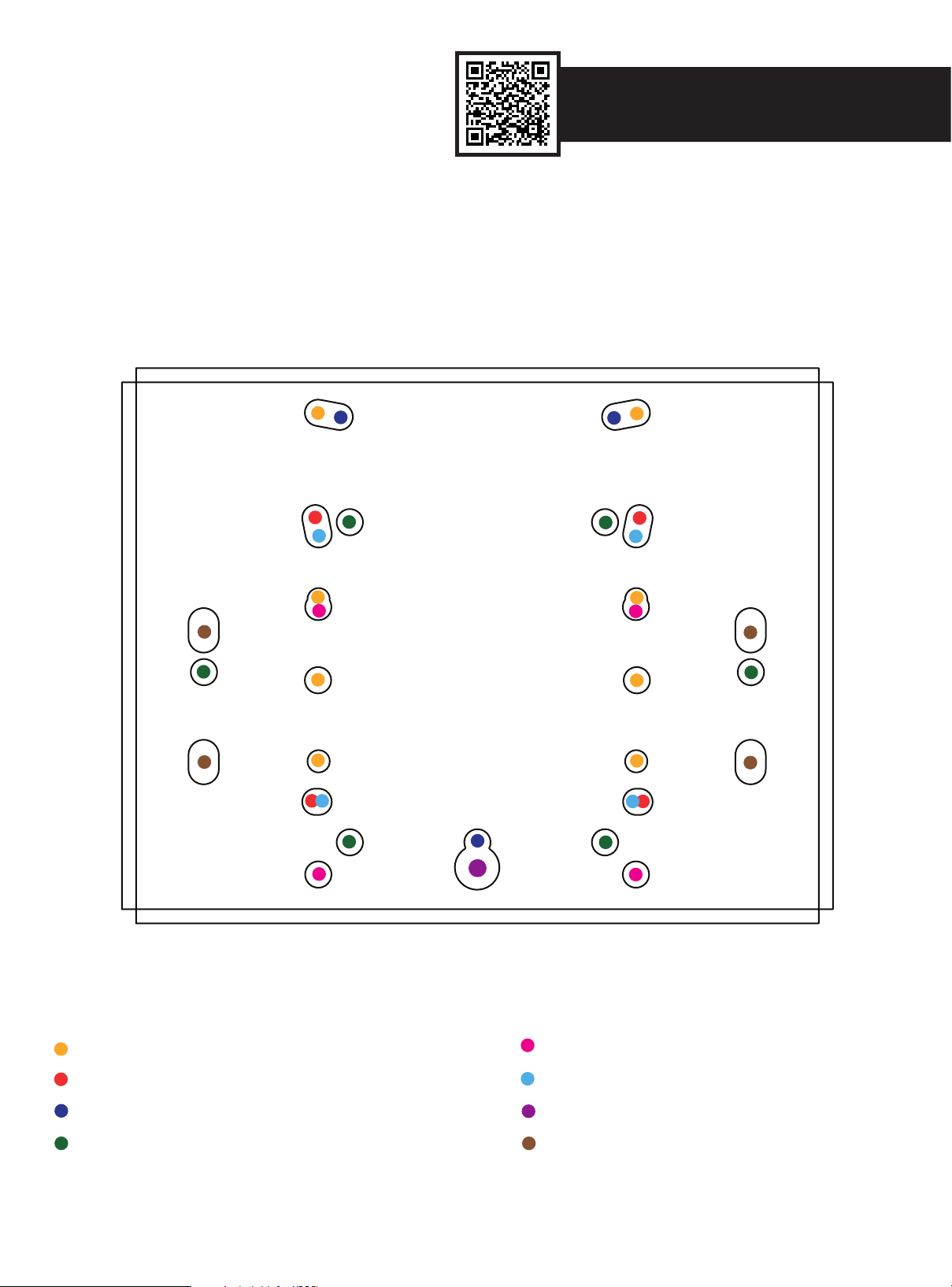
Video Instruction: bit.ly/nlrbuild
MOUNTING LOCATIONS
WHEEL PLATE
*NOT TO SCALE*
PRODUCT LEGEND:
MOZA R5 / R9 / R16 / R21 Simucube (with bottom mounting bracket)
Fanatec DD1 / DD2 / CSL DD / DD Pro Simagic Alpha
Logitech G Pro / G25 / G27 / G29 / G902 / G923 Nintendo Mario Kart
Thrustmaster T-818 / T500 RS / TGT / TSPC / TX SimXperience Accuforce Pro
7
Page 8
A) B)
PARTS:
01
A)
02
A)
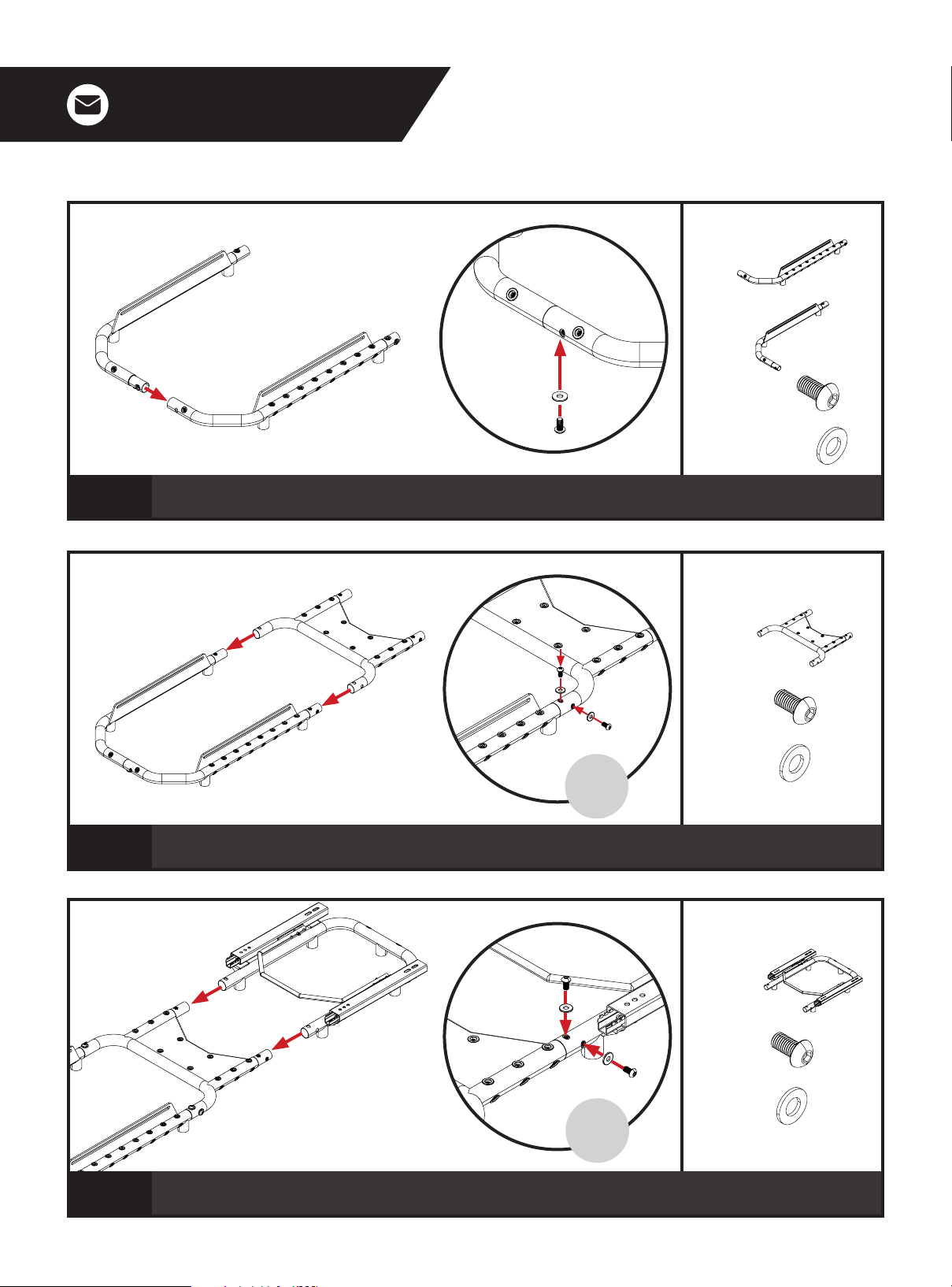
A) Align the nut inserts on the Right Pedal Frame with the mounting holes on the Left Pedal Frame.
B) Bolt through to the nut insert on the underside of frame and secure with 1 x M8 Bolt and Washer.
PARTS:
B)
Repeat
on Other
Side
A) Align the nut inserts on the Right and Left Pedal Frames with the mounting holes on the Centre
Frame. B) Bolt through and secure with 4 x M8 Bolts and Washers.
PARTS:
B)
03
Repeat
on Other
Side
A) Align the nut inserts on the Centre Frame with the mounting holes on the Rear Frame.
B) Bolt through and secure with 4 x M8 Bolts and Washers.
8
Page 9
Video Instruction: bit.ly/nlrbuild
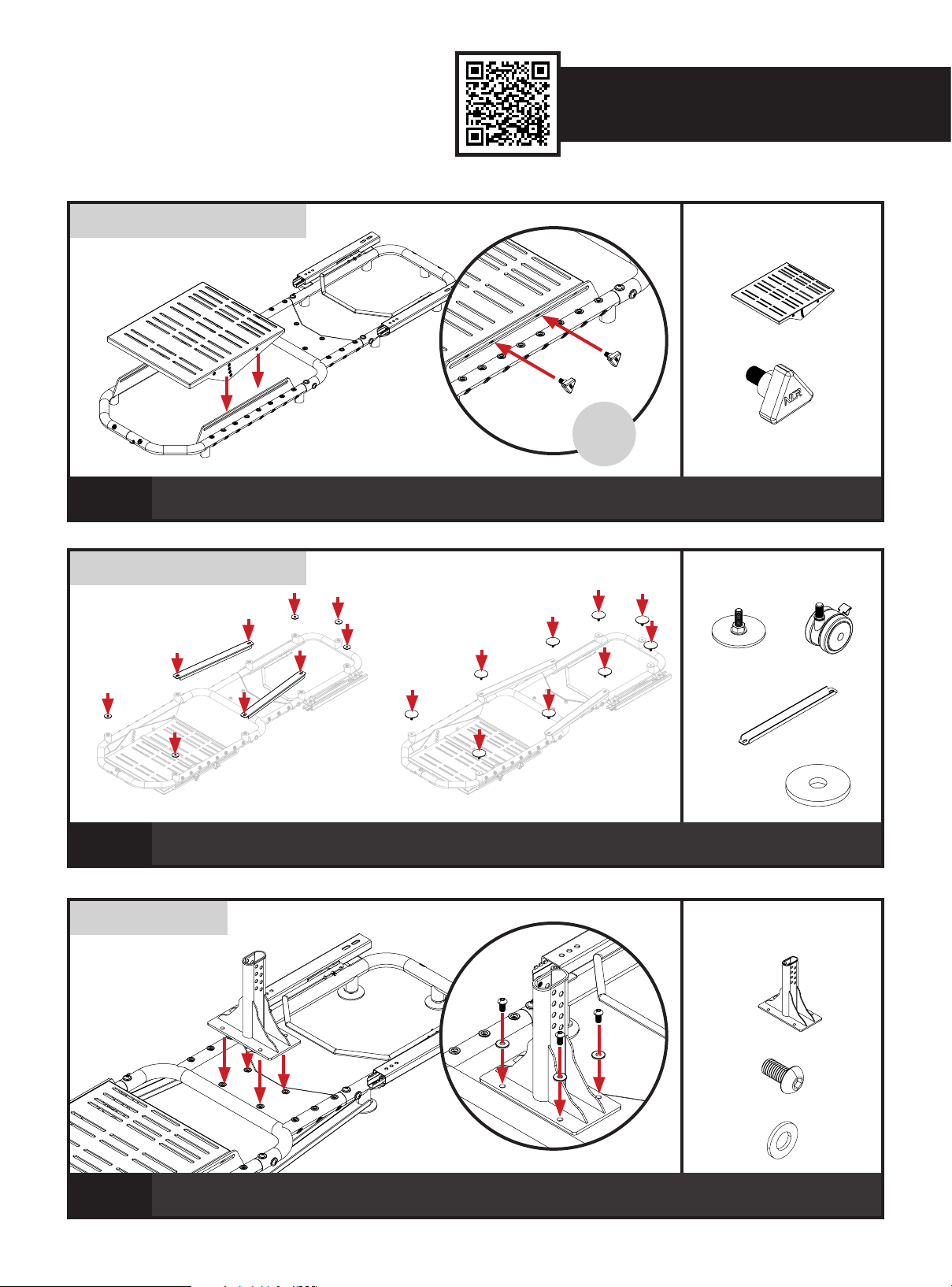
NOTE: If using Load Cell Pedals, replace M8 Knobs with
M8 20mm Bolts and Washers supplied.
04
NOTE: Flip the assembly upside down for easy installation.
If using Castor Wheels, leave middle rear mount empty.
A) Align the nut inserts on the Pedal Plate with the slots on the Right and Left Pedal Frames.
B) Bolt through and secure with 4 x NLR Knobs.
A)
B)
PARTS:
Repeat
on Other
Side
PARTS:
or
05
NOTE: Flip the assembly back
Flip the assembly upside down. A) Align 5 x Foot Spacers and 2 x Frame Braces with the footing mounts on the
bottom of the cockpit. B) Install 9 x Flat Feet or 8 x Castor Wheels into the mounting points.
upright.
A)
06
A) Align the mounting holes on the Centre Pole Base with the nut inserts on the Centre Frame.
B) Bolt through and secure with 4 x M8 Bolts and Washers.
PARTS:
B)
9
Page 10
07
A)
A)
B)
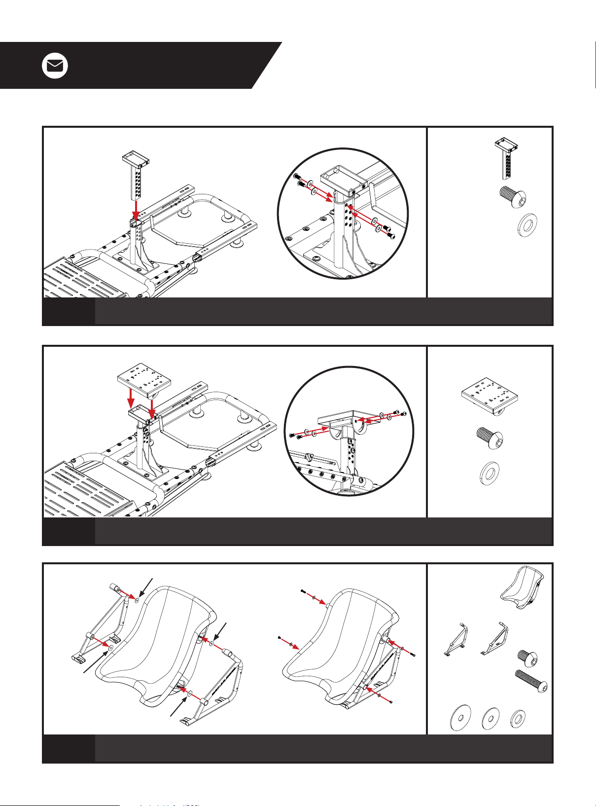
A) Align the nut inserts on the Centre Pole with the holes on the Centre Pole Base.
B) Bolt through and secure with 4 x M8 Bolts and Washers.
B)
PARTS:
wheelbase it is recommended to
use additional spare M8 16mm bolts
on Centre Pole (2x extra on each
side).
PARTS:
08
A) B)
M8 Ø35mm Washers
09
A) Align the mounting holes on the Wheel Plate with the nut inserts on the Centre Pole.
B) Bolt through and secure with 4 x M8 Bolts and Washers.
M8 Ø30mm Washers
M8 Ø30mm Washers
M8 Ø35mm Washers
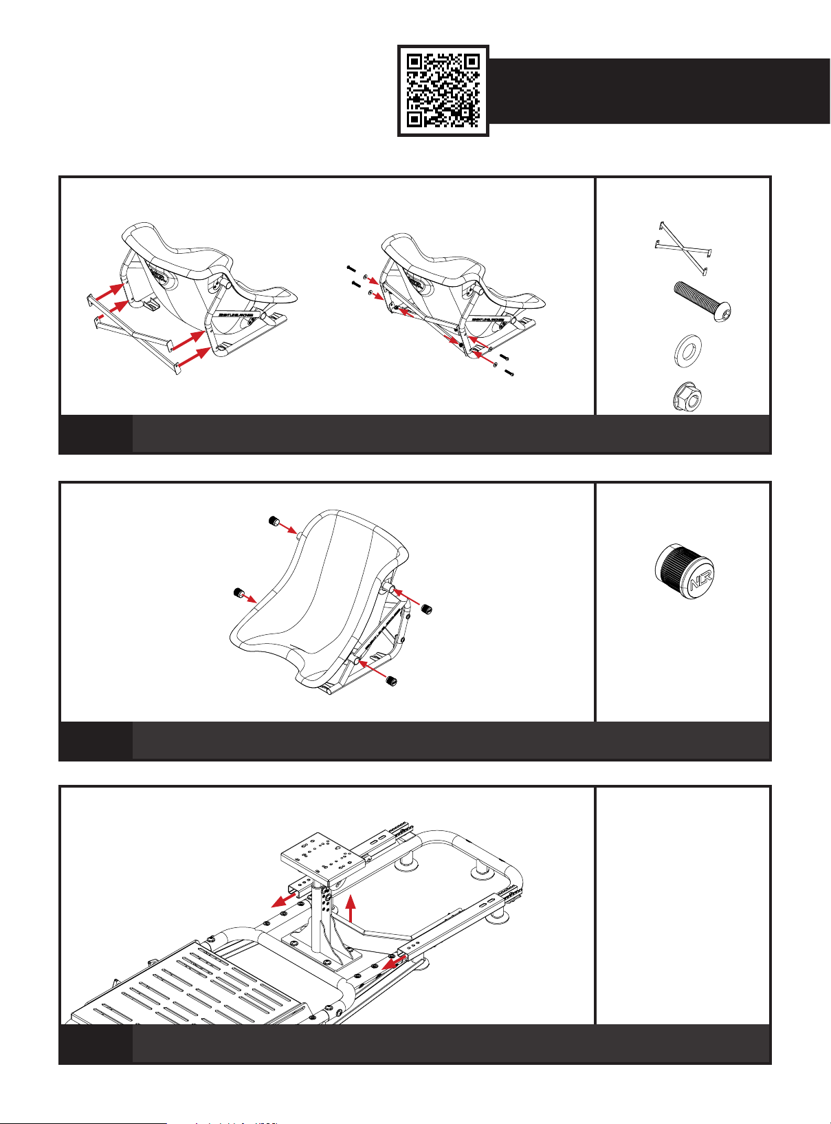
A) Align the mounting holes on the Left and Right Seat Frames with the nut inserts on the Go Kart Seat. Align 2 x Ø30mm and 2 x Ø35mm washers
in between Seat Frames and Seat. B) Bolt through and secure with 4 x M8 Bolts and Ø20mm Washers. (2 x 30mm Bolts for the upper mounts and 2
x 12mm Bolts for the lower mounts).
10
PARTS:
Page 11
A) B)
Video Instruction: bit.ly/nlrbuild
PARTS:
10
11
A) Align the mounting holes on the Seat Cross Brace with the through holes on the Left and Right Seat
Frames. B) Bolt through and secure with 4 x M8 Bolts, Washers and Flange Nuts.
PARTS:
Install 4 x End Caps onto the Left and Right Seat Frames.
PARTS:
12
Pull Seat Slider Handle upwards and slide Seat Slider Assembly forward to access front mounting
holes.
11
Page 12
PARTS:
13
14
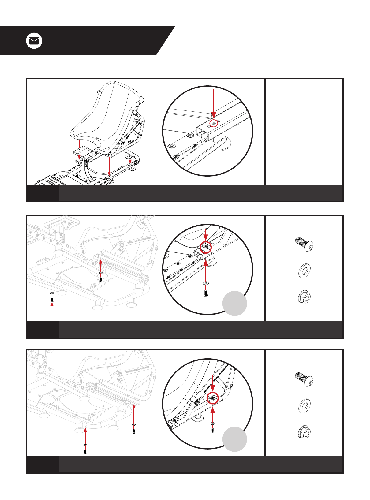
Align the mounting slots on the Left and Right Seat Frame with the middle mounting holes on the front
of the Seat Slider Assembly.
PARTS:
Repeat
on Other
Side
Bolt through the front holes and secure with 2 x M8 Bolts, Washers and Flange Nuts. Pull the Seat
Slider Handle upwards and slide the seat backwards when done.
PARTS:
15
Repeat
on Other
Side
Bolt through the rear holes and secure with 2 x M8 Bolts, Washers and Flange Nuts.
12
Page 13
A) B)
Video Instruction: bit.ly/nlrbuild
PARTS:
16
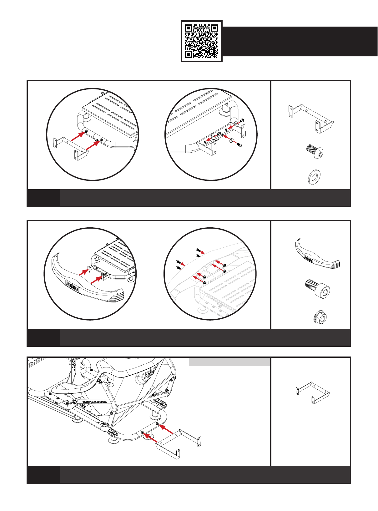
A) Align the Front Bumper Mount with the nut inserts on the front of the Pedal Frame.
B) Bolt through and secure with 3 x M8 Bolts and Washers.
A) B)
17
A) Align the Front Bumper with mounting holes on Front Bumper Mount.
B) Bolt through and secure with 4 x M8 Bolts and Flange Nuts.
NOTE: If using Buttkicker refer to STEP 29.
PARTS:
PARTS:
18
Align the Rear Bumper Mount with the nut inserts on the Rear Frame.
13
Page 14
PARTS:
19
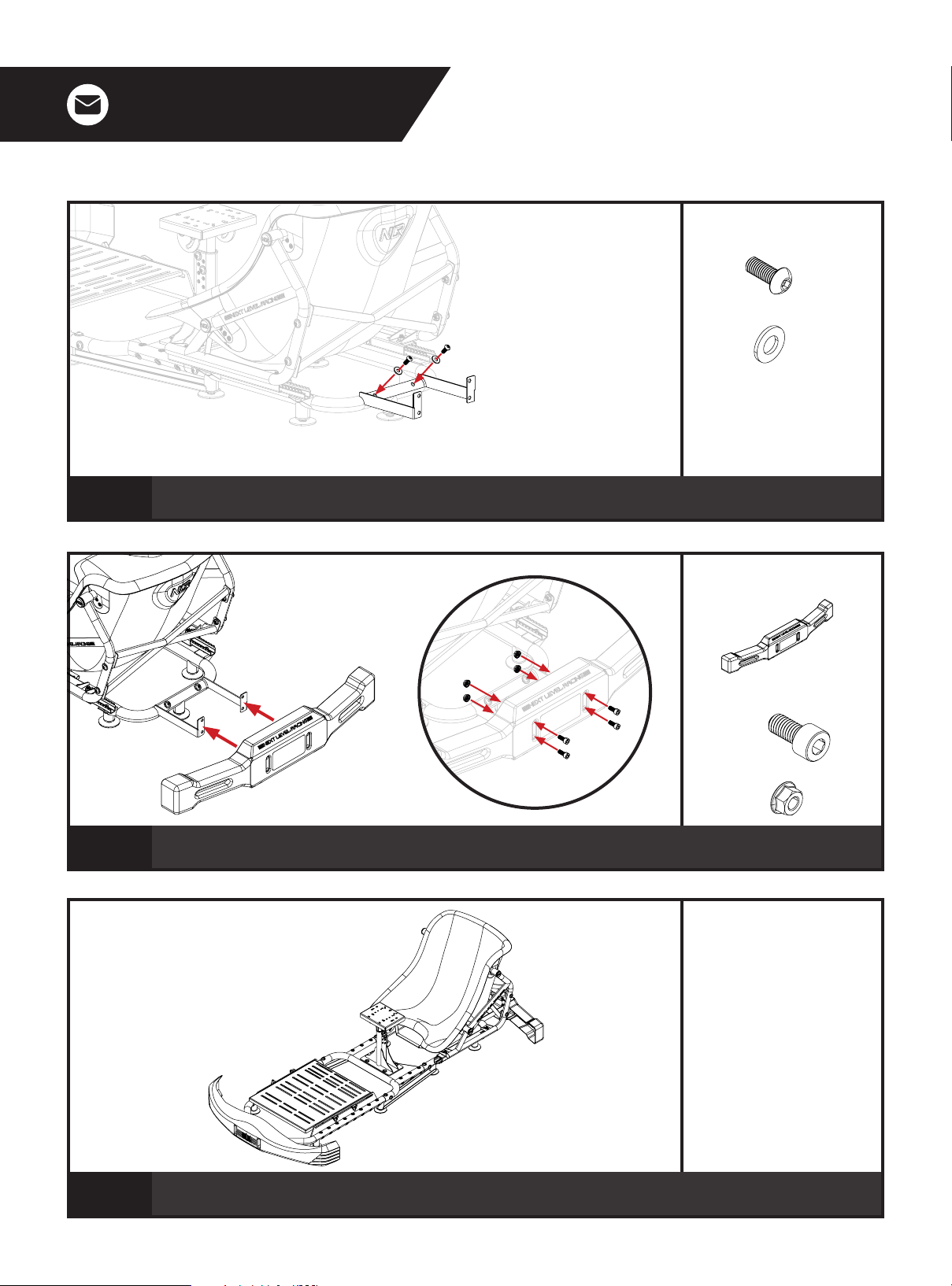
Bolt through and secure with 2 x M8 Bolts and Washers.
A) B)
20
A) Align mounting holes on Rear Bumper with Rear Bumper Mount.
B) Bolt through and secure using 4 x M8 Bolts and Flange Nuts.
PARTS:
PARTS:
21
Your Go Kart Cockpit is complete.
14
Page 15
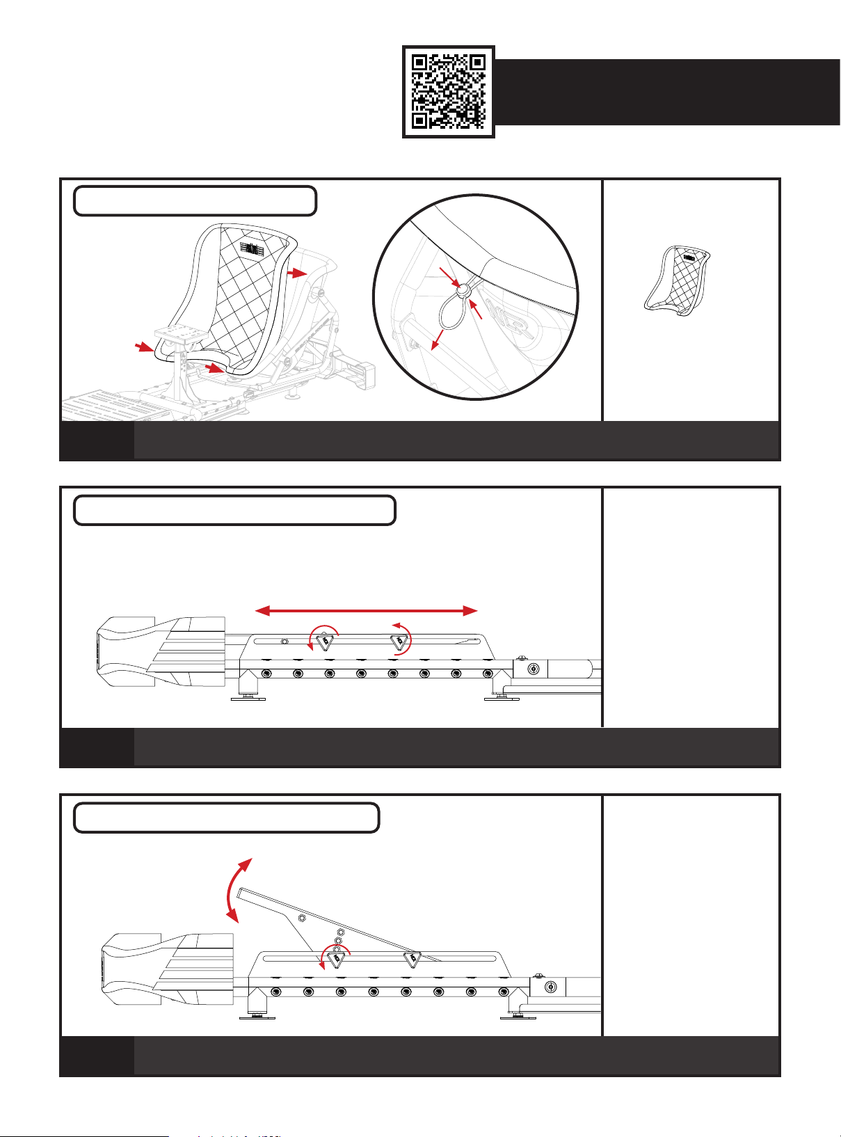
Video Instruction: bit.ly/nlrbuild
SEAT COVER INSTALLATION
22
Install the Go Kart Seat Cover starting from the bottom first. Wrap the outer lip around the seat. Pinch
drawstring release on the back and pull the drawstring to tighten.
PEDAL PLATE LATERAL ADJUSTMENT
PARTS:
separately in cold water only
PARTS:
23
Loosen the NLR Knobs securing the Pedal Plate to the Pedal Frame. Adjust to the desired position and
tighten to lock in place.
PEDAL PLATE ANGLE ADJUSTMENT
24
Remove the front NLR Knobs and loosen the rear NLR Knobs securing the Pedal Plate to the Pedal
Frame. Adjust to the desired angle, reinstall the front NLR Knobs and tighten to lock in place.
PARTS:
15
Page 16
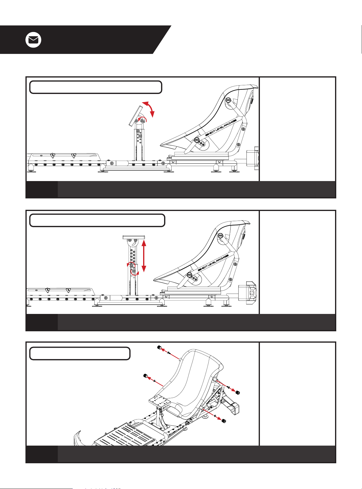
CENTRE POLE ANGLE ADJUSTMENT
25
Uninstall the rear Bolts and Washers, loosen the front Bolts securing the Wheel Plate to the Centre Pole. Adjust to
the desired angle, reinstall rear Bolts and tighten to lock in place.
CENTRE POLE HEIGHT ADJUSTMENT
PARTS:
PARTS:
26
Uninstall Bolts and Washers securing the Centre Pole to the Centre Pole Base. Adjust to the desired
height. Reinstall Bolts and tighten to lock in place.
SEAT ANGLE ADJUSTMENT
27
Remove End Caps and Bolts securing the Go Kart Seat to the Seat Frame.
16
PARTS:
Wrench to help pry out the End
Caps.
Page 17
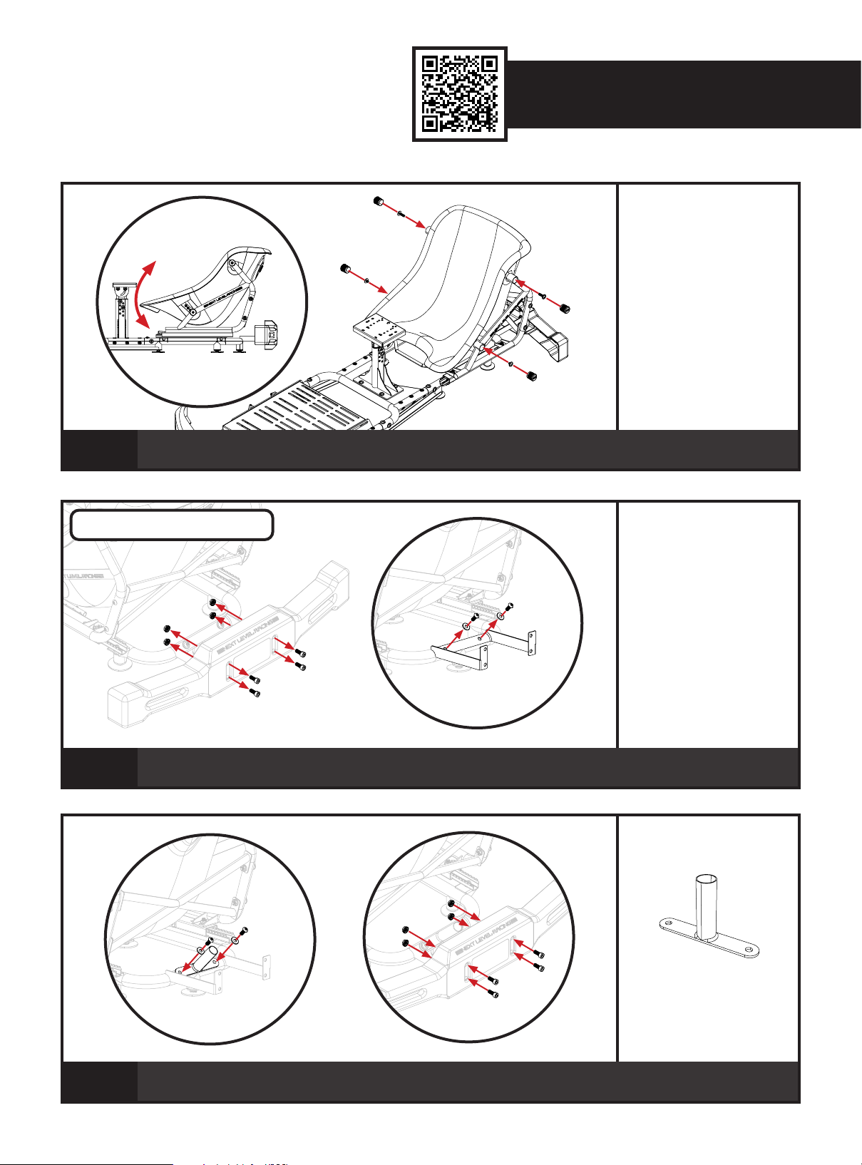
Video Instruction: bit.ly/nlrbuild
PARTS:
28
BUTTKICKER MOUNT
Adjust Go Kart Seat to the desired angle. Reinstall Bolts, tighten to lock in place. Reinstall End Caps.
A)
29
A) Uninstall Rear Bumper.
B) Uninstall Bolts and Washers securing Rear Bumper Mount to Rear Frame.
A)
PARTS:
B)
PARTS:
B)
30
A) Align Buttkicker Mount with Rear Bumper Mount holes. Reinstall previously removed Bolts and Washers.
B) Reinstall Rear Bumper.
17
Page 18
WARNING
Please do not use power tools for assembly as over tightening can damage your frame.
Avoid cross threading threaded items.
Do not force parts together.
If in doubt consult the installation video (see QR code below or contact us at [email protected]).
Hand wash Seat Cover separately in cold water only.
NOTES
ASSISTANCE
ASSEMBLY
VIDEO
bit.ly/nlrbuild
If you require further support with your product please
contact our friendly team at: [email protected]
18
Page 19
Video Instruction: bit.ly/nlrbuild
PL
Instrukcja obsługi GO KART Plus
Wiemy, że nie możesz się doczekać, aby rozpocząć wyścigi! Nie spiesz się z instrukcjami i postępuj zgodnie z tym przewodnikiem, aby złożyć swój produkt. Ustawisz się na sukces,
postępując zgodnie z instrukcją, aby w pełni zoptymalizować swój produkt.
KONTROLE PRZED WYŚCIGIEM
OSTRZEŻENIE
• Proszę nie używać elektronarzędzi do montażu, ponieważ zbyt mocne dokręcenie może uszkodzić ramę.
• Nie łącz części na siłę.
• Unikaj krzyżowania gwintowanych przedmiotów.
• W razie wątpliwości zapoznaj się z filmem instalacyjnym (zobacz kod QR poniżej lub skontaktuj się z nami pod adresem [email protected])
• Pokrowiec siedziska należy prać ręcznie tylko w zimnej wodzie.
Jeśli potrzebujesz wsparcia dotyczącego Twojego produktu, skontaktuj się z naszym przyjaznym zespołem pod adresem: [email protected]
OSTRZEŻENIE NIEBEZPIECZEŃSTWO ZADŁAWIENIA
Małe części nie są przeznaczone dla dzieci poniżej 3 lat ani osób, które mają tendencję do wkładania do ust niejadalnych przedmiotów.
POCZĄTEK
01 – Patrz obraz. A) Wyrównaj wkładki nakrętek na ramie prawego pedału z otworami montażowymi w ramie lewego pedału. B) Przykręć śrubę do wkładki nakrętki na spodzie ramy i
zabezpiecz 1 śrubą M8 i podkładką.
02 – Patrz obraz. A) Wyrównaj wkładki nakrętek na ramie prawego i lewego pedału z otworami montażowymi na ramie środkowej. B) Przykręć i zabezpiecz 4 śrubami M8 i podkładkami.
03 – Patrz obraz. A) Wyrównaj wkładki nakrętek na ramie środkowej z otworami montażowymi na ramie tylnej. B) Przykręć i zabezpiecz 4 śrubami M8 i podkładkami.
04 – Patrz obraz. A) Wyrównaj wkładki nakrętek na płycie pedału z gniazdami w prawej i lewej ramie pedału. B) Przykręć i zabezpiecz 4 pokrętłami NLR.
05 – Patrz obraz. Odwróć zespół do góry nogami. A) Wyrównaj 5 podkładek dystansowych i 2 wsporników ramy z mocowaniami podstawy na spodzie kokpitu. B) Zainstaluj 9 płaskich
nóżek lub 8 kół samonastawnych w punktach mocowania.
06 – Patrz obraz. A) Wyrównaj otwory montażowe na podstawie słupka środkowego z wkładkami nakrętek na ramie środkowej. B) Przykręć i zabezpiecz 4 śrubami M8 i podkładkami.
07 – Patrz obraz. A) Wyrównaj wkładki nakrętek na słupku środkowym z otworami w podstawie słupka środkowego. B) Przykręć i zabezpiecz 4 śrubami M8 i podkładkami.
08 – Patrz obraz. A) Wyrównaj otwory montażowe na płycie koła z wkładkami nakrętek na słupku środkowym. B) Przykręć i zabezpiecz 4 śrubami M8 i podkładkami.
09 – Patrz obraz. A) Wyrównaj otwory montażowe w lewej i prawej ramie siedziska z wkładkami nakrętek siedziska gokarta. Wyrównaj 2 podkładki o średnicy 30 mm i 2 podkładki o
średnicy 35 mm pomiędzy ramą siedziska a siedziskiem. B) Przykręć i zabezpiecz 4 śrubami M8 i podkładkami Ř20mm. (2 śruby 30 mm do górnych mocowań i 2 śruby 12 mm do dolnych
mocowań).
10 – Patrz ilustracja. A) Wyrównaj otwory montażowe na wsporniku poprzecznym siedzenia z otworami przelotowymi w lewej i prawej ramie siedziska. B) Przykręć i zabezpiecz 4 śrubami
M8, podkładkami i nakrętkami kołnierzowymi.
11 – Patrz ilustracja. Zainstaluj 4 zaślepki końcowe na lewej i prawej ramie siedziska.
12 – Patrz ilustracja. Pociągnij uchwyt suwaka siedzenia w górę i przesuń zespół suwaka siedzenia do przodu, aby uzyskać dostęp do przednich otworów montażowych.
13 – Patrz ilustracja. Wyrównaj szczeliny montażowe na lewej i prawej ramie siedziska ze środkowymi otworami montażowymi z przodu zespołu prowadnicy siedziska.
14 – Patrz ilustracja. Wkręć śruby przez przednie otwory i zabezpiecz 2 śrubami M8, podkładkami i nakrętkami kołnierzowymi. Pociągnij uchwyt suwaka siedziska do góry i po zakończeniu
przesuń siedzisko do tyłu.
15 – Patrz obraz. Wkręć śruby przez tylne otwory i zabezpiecz 2 śrubami M8, podkładkami i nakrętkami kołnierzowymi.
16 – Patrz ilustracja. A) Wyrównaj mocowanie przedniego zderzaka z wkładkami nakrętek z przodu ramy pedału. B) Przykręć i zabezpiecz 3 śrubami M8 i podkładkami.
17 – Patrz obraz. A) Wyrównaj przedni zderzak z otworami montażowymi w uchwycie przedniego zderzaka. B) Przykręć i zabezpiecz 4 śrubami M8 i nakrętkami kołnierzowymi.
18 – Patrz ilustracja. Wyrównaj mocowanie tylnego zderzaka z wkładkami nakrętek na ramie tylnej.
19 – Patrz obraz. Przykręć i zabezpiecz 2 śrubami M8 i podkładkami.
20 – Patrz obraz. A) Wyrównaj otwory montażowe na tylnym zderzaku z mocowaniem tylnego zderzaka. B) Przykręć i zabezpiecz za pomocą 4 śrub M8 i nakrętek kołnierzowych.
21 – Patrz obraz. Twój kokpit gokartowy jest gotowy.
22 – Patrz obraz. Zamontuj pokrycie siedzenia gokarta, zaczynając od dołu. Owiń zewnętrzną krawędź wokół siedzenia. Ściśnij zwolnienie sznurka z tyłu i pociągnij za sznurek, aby go
zacisnąć.
23 – Patrz obraz. Poluzuj pokrętła NLR mocujące płytkę pedału do ramy pedału. Dostosuj do żądanej pozycji i dokręć, aby zablokować na miejscu.
24 – Patrz ilustracja. Zdejmij przednie pokrętła NLR i poluzuj tylne pokrętła NLR mocujące płytkę pedału do ramy pedału. Ustaw żądany kąt, ponownie zamontuj przednie pokrętła NLR i
dokręć, aby zablokować.
25 – Patrz obraz. Odkręć tylne śruby i podkładki, poluzuj przednie śruby mocujące tarczę koła do słupka środkowego. Ustaw żądany kąt, ponownie zamontuj tylne śruby i dokręć, aby
zablokować.
26 – Patrz ilustracja. Odkręć śruby i podkładki mocujące słupek środkowy do podstawy słupka środkowego. Dostosuj do żądanej wysokości. Ponownie zamontuj śruby i dokręć, aby
zablokować na miejscu.
27 – Patrz obraz. Zdejmij zaślepki końcowe i śruby mocujące siedzisko gokarta do ramy siedziska.
28 – Patrz ilustracja. Ustaw siodełko gokartowe pod żądanym kątem. Ponownie zamontuj śruby, dokręć, aby zablokować na miejscu. Zainstaluj ponownie zaślepki.
29 – Patrz obraz. A) Zdemontuj tylny zderzak. B) Odkręć śruby i podkładki mocujące mocowanie tylnego zderzaka do tylnej ramy.
30 – Patrz obraz. A) Wyrównaj mocowanie Buttkicker z otworami mocowania tylnego zderzaka. Zainstaluj ponownie usunięte wcześniej śruby i podkładki. B) Ponownie zamontuj tylny
zderzak.
OSTRZEŻENIE
• Proszę nie używać elektronarzędzi do montażu, ponieważ zbyt mocne dokręcenie może uszkodzić ramę.
• Nie łącz części na siłę.
• Unikaj krzyżowania gwintowanych przedmiotów.
• W razie wątpliwości zapoznaj się z filmem instalacyjnym (zobacz kod QR poniżej lub skontaktuj się z nami pod adresem [email protected])
• Pokrowiec siedziska należy prać ręcznie tylko w zimnej wodzie.
29
Page 20

 Loading...